US6070898A - Suspension system for a wheelchair - Google Patents
Suspension system for a wheelchairDownload PDFInfo
- Publication number
- US6070898A US6070898AUS09/134,286US13428698AUS6070898AUS 6070898 AUS6070898 AUS 6070898AUS 13428698 AUS13428698 AUS 13428698AUS 6070898 AUS6070898 AUS 6070898A
- Authority
- US
- United States
- Prior art keywords
- suspension
- structural member
- resilient
- members
- structural
- Prior art date
- Legal status (The legal status is an assumption and is not a legal conclusion. Google has not performed a legal analysis and makes no representation as to the accuracy of the status listed.)
- Expired - Fee Related
Links
Images


Classifications
- A—HUMAN NECESSITIES
- A61—MEDICAL OR VETERINARY SCIENCE; HYGIENE
- A61G—TRANSPORT, PERSONAL CONVEYANCES, OR ACCOMMODATION SPECIALLY ADAPTED FOR PATIENTS OR DISABLED PERSONS; OPERATING TABLES OR CHAIRS; CHAIRS FOR DENTISTRY; FUNERAL DEVICES
- A61G5/00—Chairs or personal conveyances specially adapted for patients or disabled persons, e.g. wheelchairs
- A61G5/04—Chairs or personal conveyances specially adapted for patients or disabled persons, e.g. wheelchairs motor-driven
- A61G5/041—Chairs or personal conveyances specially adapted for patients or disabled persons, e.g. wheelchairs motor-driven having a specific drive-type
- A61G5/043—Mid wheel drive
- A—HUMAN NECESSITIES
- A61—MEDICAL OR VETERINARY SCIENCE; HYGIENE
- A61G—TRANSPORT, PERSONAL CONVEYANCES, OR ACCOMMODATION SPECIALLY ADAPTED FOR PATIENTS OR DISABLED PERSONS; OPERATING TABLES OR CHAIRS; CHAIRS FOR DENTISTRY; FUNERAL DEVICES
- A61G5/00—Chairs or personal conveyances specially adapted for patients or disabled persons, e.g. wheelchairs
- A61G5/10—Parts, details or accessories
- A61G5/1078—Parts, details or accessories with shock absorbers or other suspension arrangements between wheels and frame
- A—HUMAN NECESSITIES
- A61—MEDICAL OR VETERINARY SCIENCE; HYGIENE
- A61G—TRANSPORT, PERSONAL CONVEYANCES, OR ACCOMMODATION SPECIALLY ADAPTED FOR PATIENTS OR DISABLED PERSONS; OPERATING TABLES OR CHAIRS; CHAIRS FOR DENTISTRY; FUNERAL DEVICES
- A61G5/00—Chairs or personal conveyances specially adapted for patients or disabled persons, e.g. wheelchairs
- A61G5/10—Parts, details or accessories
- A61G5/1089—Anti-tip devices
- B—PERFORMING OPERATIONS; TRANSPORTING
- B60—VEHICLES IN GENERAL
- B60G—VEHICLE SUSPENSION ARRANGEMENTS
- B60G11/00—Resilient suspensions characterised by arrangement, location or kind of springs
- B60G11/22—Resilient suspensions characterised by arrangement, location or kind of springs having rubber springs only
- B60G11/225—Neidhart type rubber springs
- B—PERFORMING OPERATIONS; TRANSPORTING
- B60—VEHICLES IN GENERAL
- B60K—ARRANGEMENT OR MOUNTING OF PROPULSION UNITS OR OF TRANSMISSIONS IN VEHICLES; ARRANGEMENT OR MOUNTING OF PLURAL DIVERSE PRIME-MOVERS IN VEHICLES; AUXILIARY DRIVES FOR VEHICLES; INSTRUMENTATION OR DASHBOARDS FOR VEHICLES; ARRANGEMENTS IN CONNECTION WITH COOLING, AIR INTAKE, GAS EXHAUST OR FUEL SUPPLY OF PROPULSION UNITS IN VEHICLES
- B60K7/00—Disposition of motor in, or adjacent to, traction wheel
- B60K7/0007—Disposition of motor in, or adjacent to, traction wheel the motor being electric
- A—HUMAN NECESSITIES
- A61—MEDICAL OR VETERINARY SCIENCE; HYGIENE
- A61G—TRANSPORT, PERSONAL CONVEYANCES, OR ACCOMMODATION SPECIALLY ADAPTED FOR PATIENTS OR DISABLED PERSONS; OPERATING TABLES OR CHAIRS; CHAIRS FOR DENTISTRY; FUNERAL DEVICES
- A61G5/00—Chairs or personal conveyances specially adapted for patients or disabled persons, e.g. wheelchairs
- A61G5/06—Chairs or personal conveyances specially adapted for patients or disabled persons, e.g. wheelchairs with obstacle mounting facilities, e.g. for climbing stairs, kerbs or steps
- B—PERFORMING OPERATIONS; TRANSPORTING
- B60—VEHICLES IN GENERAL
- B60G—VEHICLE SUSPENSION ARRANGEMENTS
- B60G2300/00—Indexing codes relating to the type of vehicle
- B60G2300/24—Wheelchairs
- B—PERFORMING OPERATIONS; TRANSPORTING
- B60—VEHICLES IN GENERAL
- B60K—ARRANGEMENT OR MOUNTING OF PROPULSION UNITS OR OF TRANSMISSIONS IN VEHICLES; ARRANGEMENT OR MOUNTING OF PLURAL DIVERSE PRIME-MOVERS IN VEHICLES; AUXILIARY DRIVES FOR VEHICLES; INSTRUMENTATION OR DASHBOARDS FOR VEHICLES; ARRANGEMENTS IN CONNECTION WITH COOLING, AIR INTAKE, GAS EXHAUST OR FUEL SUPPLY OF PROPULSION UNITS IN VEHICLES
- B60K7/00—Disposition of motor in, or adjacent to, traction wheel
- B60K2007/0046—Disposition of motor in, or adjacent to, traction wheel the motor moving together with the vehicle body, i.e. moving independently from the wheel axle
- B—PERFORMING OPERATIONS; TRANSPORTING
- B60—VEHICLES IN GENERAL
- B60K—ARRANGEMENT OR MOUNTING OF PROPULSION UNITS OR OF TRANSMISSIONS IN VEHICLES; ARRANGEMENT OR MOUNTING OF PLURAL DIVERSE PRIME-MOVERS IN VEHICLES; AUXILIARY DRIVES FOR VEHICLES; INSTRUMENTATION OR DASHBOARDS FOR VEHICLES; ARRANGEMENTS IN CONNECTION WITH COOLING, AIR INTAKE, GAS EXHAUST OR FUEL SUPPLY OF PROPULSION UNITS IN VEHICLES
- B60K7/00—Disposition of motor in, or adjacent to, traction wheel
- B60K2007/0069—Disposition of motor in, or adjacent to, traction wheel the motor axle being perpendicular to the wheel axle
- B60K2007/0076—Disposition of motor in, or adjacent to, traction wheel the motor axle being perpendicular to the wheel axle the motor axle being horizontal
- B—PERFORMING OPERATIONS; TRANSPORTING
- B60—VEHICLES IN GENERAL
- B60L—PROPULSION OF ELECTRICALLY-PROPELLED VEHICLES; SUPPLYING ELECTRIC POWER FOR AUXILIARY EQUIPMENT OF ELECTRICALLY-PROPELLED VEHICLES; ELECTRODYNAMIC BRAKE SYSTEMS FOR VEHICLES IN GENERAL; MAGNETIC SUSPENSION OR LEVITATION FOR VEHICLES; MONITORING OPERATING VARIABLES OF ELECTRICALLY-PROPELLED VEHICLES; ELECTRIC SAFETY DEVICES FOR ELECTRICALLY-PROPELLED VEHICLES
- B60L2220/00—Electrical machine types; Structures or applications thereof
- B60L2220/40—Electrical machine applications
- B60L2220/46—Wheel motors, i.e. motor connected to only one wheel
- Y—GENERAL TAGGING OF NEW TECHNOLOGICAL DEVELOPMENTS; GENERAL TAGGING OF CROSS-SECTIONAL TECHNOLOGIES SPANNING OVER SEVERAL SECTIONS OF THE IPC; TECHNICAL SUBJECTS COVERED BY FORMER USPC CROSS-REFERENCE ART COLLECTIONS [XRACs] AND DIGESTS
- Y10—TECHNICAL SUBJECTS COVERED BY FORMER USPC
- Y10S—TECHNICAL SUBJECTS COVERED BY FORMER USPC CROSS-REFERENCE ART COLLECTIONS [XRACs] AND DIGESTS
- Y10S180/00—Motor vehicles
- Y10S180/907—Motorized wheelchairs
Definitions
- This inventionrelates in general to wheelchairs and more particularly, to wheelchair suspension systems. Most particularly, the invention relates to resilient wheelchair suspensions that support the wheelchair wheels independently of one another.
- Wheelchairsgenerally include a frame that supports a pair of drive wheels and a pair of front casters.
- the drive wheels and castersare typically rigidly supported by the wheelchair frame.
- the drive wheelsmake contact with the ground and are driven to propel the wheelchair.
- the drive wheelsmay be driven manually or powered by an electrical motor.
- the wheelchairsupports a seat assembly comprising a seat and a backrest. The seat assembly is oriented above and between the drive wheels and the front casters to provide stability.
- a problem with wheelchairsis that the drive wheels and casters typically fail to maintain contact with the ground as the wheelchair negotiates obstacles or irregular ground surfaces.
- Various attemptshave been made to overcome this problem.
- the Booth patentdescribes a suspension comprising a plate carrying a wheel unit and a bogie system.
- the bogie systemcomprises two bogie units.
- Each bogie unitincludes a drive wheel and a caster wheel attached to a frame member.
- the frame memberspivot about a common transverse axis defined by brackets mounted to the plate to maintain contact with the ground.
- Another attempt to maintain contact between the wheel and the groundis set forth in International Patent Application No. PCT/SE89/00647, which describes a wheelchair chassis having a central, transverse main shaft with two drive wheels, and a front and rear pair of wheels, each carried by individual supporting arms which are swingable in a plane.
- anti-tip caster wheelsare often provided rearward of the drive wheels. These anti-tip caster wheels are often mounted on arms rigidly coupled to the support frame and are angled downward to a level just above the ground. As the wheelchair begins to tip backwards, the anti-tip caster wheels engage the ground to prevent further tipping.
- a resilient device having deformable cushionsis described in U.S. Pat. No. 2,729,442, issued to Hermann J. Neidhart.
- the deviceincludes an outer member and an inner member, each of which are generally square in cross-section. Pockets are formed between the outer and inner members for receiving elastic cushioning elements.
- the outer and inner membersmay be of any desired length and are substantially concentric with each other and mounted for relative coaxial rotation.
- the cushioning elementsare in the form of round rods and made of rubber. The cushioning elements are radially compressed to fit in the pockets. When a load is applied to the device in such a manner so as to rotate the inner member relative to the outer member, the cushioning elements are compressed between and outer and inner members.
- This inventionrelates to a wheelchair suspension system comprising a pair of resilient front suspension members and resilient drive wheel suspension members.
- the resilient front suspension membersare attached to the front end of the wheelchair base frame assembly.
- the resilient drive wheel suspension membersare attached to opposite sides of the base frame assembly in a spaced apart relation relative to the resilient front suspension members.
- Each one of the resilient front suspension memberssupports a front wheel and each one of the resilient drive wheel suspension members supports a drive wheel.
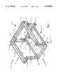
- FIG. 1is a rear perspective view of a base frame assembly useful with the wheelchair suspension system of the invention.
- FIG. 2is a rear perspective view of the base frame assembly shown in FIG. 1, further showing resilient suspension members of the invention attached to the base frame assembly for supporting the wheelchairs wheels, and drive motors and an electronic controller for driving the wheelchair drive wheels.
- FIG. 3is an exploded perspective view of a resilient rear suspension member of the invention.
- FIG. 4is an enlarged sectional view of a portion of the resilient rear suspension member shown in FIG. 3.
- FIG. 5is an enlarged sectional view of a portion of a resilient drive wheel suspension member of the invention.
- FIG. 6is an enlarged side elevational view of the resilient drive wheel suspension member shown in FIG. 5 attached to a side of the base frame assembly.
- FIG. 7is an elevational view of the base frame assembly showing relative locations of the resilient front suspension members and the resilient rear suspension members of the invention.
- FIG. 8is an exploded perspective view of the resilient drive wheel suspension member shown in FIGS. 5 and 6.
- FIG. 9is an elevational view of an alternative resilient element.
- FIG. 10is an elevational view of another alternative resilient element.
- FIG. 11is an elevational view of yet another alternative resilient element.
- FIG. 12is a perspective view of an alternative resilient drive wheel suspension member.
- FIG. 1a power wheelchair base frame assembly 10 for supporting a wheelchair seat assembly (not shown). It should be understood that the base frame assembly 10 could be adapted to support any number of suitable wheelchair seat assemblies. It should also be understood that a wheelchair seat assembly could be attached to the base frame assembly 10 in any suitable manner.
- the base frame assembly 10has opposite sides 12, 14, a front end 16, and a rear end 18.
- a footrest 26(shown in FIG. 2) extends from the front end 16 of the base frame assembly 10.
- the base frame assemblyfurther includes an upper frame structure 20 and a lower frame structure 22.
- the upper frame structure 20includes opposite sides 24, 28 and a front end 30.
- the lower frame structure 22includes opposite sides 32, 34, a front end 36, and a rear end 38.
- the upper frame structure 20is spaced apart from the lower frame structure 22 and fixed relative to the lower frame structure 22 by vertically extending structural elements 40, 42.
- the vertically extending structural elements 40, 42have lower ends 46, 48 connected to corners of the lower frame structure 22 and upper ends 50, 52 connected to corners of the upper frame structure 20.
- This configurationforms a base frame assembly having a substantially rectangular construction.
- a substantially planar panel 54is rigidly connected to the opposite sides 32, 34, the front end 36, and the rear end 38 of the lower frame structure 22 so as to be rigidly supported by the lower frame structure 22.
- the planar panel 54is provided to support a battery (not shown). It should be understood that this base frame assembly 10 described is for merely illustrative purposes and that the invention may be adapted for use with other wheelchair frame assemblies.
- the base frame assembly 10supports independent resilient suspension members, generally indicated at 56, 58 and 60 (shown more clearly in FIG. 8).
- the independent resilient suspension membersinclude resilient front suspension members 56, resilient rear suspension members 58, and resilient drive wheel suspension members 60.
- the resilient front suspension members 56are attached to opposite sides 12, 14 of the front end 16 of the base frame assembly 10.
- the resilient rear suspension members 58are attached to opposite sides 12, 14 of the rear end 18 of the base frame assembly 10.
- the resilient drive wheel suspension members 60are attached to opposite sides 12, 14 of the base frame assembly 10 intermediate the resilient front suspension members 56 and the resilient rear suspension members 58.
- Each of the resilient suspension members 56, 58, 60supports a wheel.
- each of the resilient front suspension members 56supports a front wheel 62.
- the front wheels 62are preferably casters.
- Each of the resilient rear suspension members 58supports a rear wheel 64.
- the rear wheels 64may also be casters.
- each of the resilient drive wheel suspension members 60supports a drive wheel 66.
- the drive wheels 66are preferably driven by a prime mover, such as the electric motor assembly 68 shown.
- the electric motor assembly 68may be controlled by an electrical controller 44 responsive to the occupant's voice or to signals produced by a control wand supported on the armrest (not shown) of the wheelchair.
- the armrestcould be an integral part of the wheelchair seat assembly.
- FIG. 3An example of a resilient suspension member is shown in FIG. 3. Although the resilient suspension member shown is a resilient rear suspension member 58, the resilient front suspension member 56 is configured in a similar manner.
- the resilient rear suspension member 58includes an outer structural member 70 and an inner structural member 72 disposed within the outer structural member 70. It is preferable that the outer structural member 70 and the inner structural member 72 be metal. However, it is conceivable that other materials may be suitable for carrying out the invention. Although the outer structural member 70 and the inner structural member 72 are substantially square, other geometric shapes may be employed. As shown in FIG. 4, the outer structural member 70 is positioned out of phase relative to the inner structural member 72 so as to form a plurality of pockets 74 between the outer structural member 70 and the inner structural member 72.
- the outer structural member 70is positioned ninety degrees out of phase relative to the inner structural member 72, other phase angles may be suitable for carrying out the invention.
- the relative positions of the outer structural member 70 and the inner structural member 72may largely depend on the geometric shapes of the structural members 70, 72.
- a resilient element 76is disposed within each of the pockets 74.
- the resilient element 76is preferably an elastomeric material. Rubber or vulcanized rubber may be a suitable material. It should be understood that the resilient element 76 may be a natural and synthetic material. Urethanes or other polymers may be suitable for carrying out the invention.
- the inner structural member 72is rotatable relative to the outer structural member 70 along an axis of rotation, indicated at A. The resistance of the resilient element 76 to compression limits the rotation or torsional movement of the inner structural member 72.
- a set of spaced apart tabsextends from an outer surface of the outer structural member 70.
- the tabs 78are provided to engage the rear end 38 of the lower frame structure 22, as is clearly shown in FIG. 2.
- the tabs 78have holes 98 which co-align with corresponding holes (not shown) in the rear end 38 of the lower frame structure 22 to receive a fastener (not shown) for affixing the outer structural member 70 to the base frame assembly 10.
- the resilient front suspension member 56may be attached to the front end 16 of the base frame assembly 10, as shown in FIG. 7, in a similar manner as well.
- a lever 80is shown attached to the inner structural member 72.
- the lever 80is provided for supporting the rear wheel 64.
- the rear wheel 64is supported at an end 82 of the lever 80 remote from the inner structural member 72.
- the lever 80may support the rear wheel 64 in any conventional manner.
- a caster housing 84may be provided at the end 82 of the lever 80 for rotatably receiving a caster stem (not shown).
- An annular space(not shown) may be defined between an inner surface of the housing and the caster stem to receive bearings (also not shown).
- An end 83 of the inner structural member 72 remote from the lever 80has a threaded bore 86 for receiving a threaded stud 88.
- the threaded stud 88extends through a cap 90 for the outer structural member 70, and further through a series of washers 92, 94.
- a lock nut 96is engageable with the threaded stud 88 so as to confine the outer structural member 70 between the lever 80 and the cap 90.
- Linear bearings 91, 93may be employed between the lever 80 and the structural members 70, 72, and further between the inner structural member 72 and the cap 90 to eliminate or reduce axial frictional forces. It should be understood that other friction reduction elements, such as nylon washers (not shown), may be employed as well.
- the resilient front suspension members 56 and the resilient rear suspension members 58are attached to the base frame assembly 10 at different relative elevations. It should also be noted that the lengths of the levers 80, 81 and the angular displacement of the levers 80, 81 vary between the resilient front suspension members 56 and the resilient rear suspension members 58. It should further be noted that the front wheels 62 and the rear wheels 64 may be of different dimensions. These characteristics are dependent on one another and may be largely dependent on other physical characteristics of the wheelchair as well.
- the resilient front suspension members 56each support a traction acceleration ramp 100.
- the traction acceleration ramps 100are preferably welded to the resilient front suspension members 56. However, it should be understood that the traction acceleration ramps 100 may be attached in any suitable manner.
- the resilient drive wheel suspension members 60are configured in a manner similar to that of the resilient rear suspension members 58 and the resilient front suspension members 56. As shown in FIG. 8, the resilient drive wheel suspension members 60 each include an outer structural member 102 and an inner structural member 104 disposed within the outer structural member 102. A plurality of pockets 106 (more clearly shown in FIG. 5) are defined between the outer structural member 102 and the inner structural member 104. A resilient element 108 is disposed within each of the pockets 106 (also shown more clearly in FIG. 5).
- the resilient element 108is preferably an elastomeric material. As set forth above, the resilient element 108 may be rubber or vulcanized rubber. The resilient element 108 may be a natural or synthetic material. Urethane or other polymers may be suitable for carrying out the invention.
- the inner structural member 104is rotatable relative to the outer structural member 102 along an axis of rotation, indicated at B, and the resistance of the resilient element 108 to compression limits such rotation.
- the tabs 110are provided to support the electric motor assembly 68.
- the tabs 110define a motor mount.
- the tabs 110have holes 115 that co-align with corresponding holes (not shown) in the electric motor assembly 68 (shown in FIG. 2) and are adapted to receive fasteners (not shown) for affixing the electric motor assembly 68 to the tabs 110.
- the outer structural member 102is disposed between two spaced apart brackets 112. Spacers 114 may be provided between the inner structural member 104 and the brackets 112 so as to center the outer structural member 102 between the brackets 112.
- the brackets 112 shownare triangular shaped and have an offset upper end 111.
- the offset upper end 111is provided to compensate for the difference in the axial width of the outer structural member 102 and the sides 24, 28 of the upper frame structure 20 of the base frame assembly 10 to which the brackets 112 attach.
- the offset upper end of each of the brackets 112have holes 117 that co-align with holes (not shown) in the opposite sides 24, 28 of the upper frame structure 20.
- Threaded fasteners 116pass through the holes 117 in the brackets 112 and further through the holes in the sides 24, 28 of the upper frame structure 20.
- the threaded fasteners 116are engageable with lock nuts 118 to attach the brackets 112 to the upper frame structure 20 (as shown in FIGS. 6 and 7).
- An axial bore 120passes through the inner structural member 104.
- a threaded fastener 122passes through the brackets 112, the inner structural member 104, and a series of washers 121, 123 and spacers 125.
- a lock nut 113engages the threaded fastener 122 to retain the outer structural member 102 within the inner structural member 104 and between the brackets 112.
- the resilient elements 76, 108 set forth aboveeach preferably have a cross-section larger than the cross-section of the pockets 74, 106 so as to be compressed when in the pockets 74, 106.
- the resilient elements 76, 108may be formed integrally positioned with one another, as shown in the drawings, or may be separate cylindrically shaped resilient members (not shown) independent of one another. Resilient elements 76, 108 formed integrally with one another may be more effective in restricting the rotational displacement of the inner structural members 72, 104 relative to the outer structural members 70, 102.
- the inventionis not limited to resilient elements that are an extruded elastomer.
- An elastomermay be injected into the pockets 74, 106.
- An injected elastomerwould bond to the outer structural members 70, 102 as well as the inner structural members 72, 104.
- resilient suspension members in the foregoing descriptionare merely illustrative and that other resilient suspension configurations may be suitable for carrying out the invention.
- a resilient element in the form in a spring 124is shown of FIG. 9.
- a resilient member in the form of a hydraulic actuator 126is shown in FIG. 10.
- FIG. 11shows a resilient material 128 intermediate a displaceable structural member, such as the resilient drive wheel suspension member 60, and a fixed structural member, such as one of the sides 24 of the upper frame structure 20 of the base frame assembly 10.
- a displaceable structural membersuch as the resilient drive wheel suspension member 60
- a fixed structural membersuch as one of the sides 24 of the upper frame structure 20 of the base frame assembly 10.
- the resilient drive wheel suspension members 60may be provided with a traction link arm 130 for supporting a traction link roller 132.
- the traction link roller 132is rotatable about an axis of rotation C that is spaced apart and substantially parallel to the axis of rotation B of the resilient drive wheel suspension member 60.
- the traction link roller 132is engageable with the traction acceleration ramp 100.
- the traction link arm 130, the traction link roller 132, and the traction acceleration ramp 100cooperatively form a traction linkage assembly, generally indicated at 134 (shown in FIG. 7).
- the traction linkage assembly 134ensures that a continuous contact is maintained between the drive wheels 66 and the ground.
- the wheels 62, 64, 66rotate in the direction of the arrows D, wheelchair progresses forward in the direction of the arrow E.
- the resilient suspension members 56, 58, 60absorb shock sustained by the wheelchair when traversing an irregular ground surface to provide comfortable transportation. This is accomplished because of the compressive and decompressive nature of the resilient elements 76, 108.
- the front wheels 62are spaced apart from the drive wheels 66 sufficiently to reduce the risk of the wheelchair tipping forward.
- the rear wheels 64are spaced apart from the drive wheels 66 sufficiently to reduce the risk of the wheelchair tipping rearward.
- the resilient front suspension members 56pivot about an axis of rotation in the direction of the arrow F. As this occurs, the resilient front suspension members 56 approach the traction link rollers 132.
- the traction link roller 132Upon contacting the traction acceleration ramp 100, the traction link roller 132 progresses up the traction acceleration ramp 100 and the resilient drive wheel suspension members 60 pivot about the axis of rotation B in the direction of the arrow G. As this occurs, the drive wheel 66 is forced downward so as to remain in contact with the ground. As the wheelchair tips rearward, the rear wheels 64 maintain contact with the ground.
- the resilient rear suspension members 58may pivot about the axis of rotation A in the direction of the arrow H so as to absorb shock encountered by the rearward tipping.
- the resilient suspension members 56, 58, 60return to a normal position.
- the resilient elements 76, 108are compressed.
- the resilient elements 76, 108decompress.
- the resistance to compressionincreases as the as the compression increases so as to smoothly absorb shock or abrupt jolts.
- the resistance to compressiondecreases as the resilient element 76, 108 decompresses to smoothly urge the resilient suspension members 56, 58, 60 back to a normal position.
- the front wheels 62reduce the risk of the wheelchair tilting forward.
- the resilient rear suspension members 58function as an anti-tip device to limit the amount of rearward tipping of the wheelchair.
- a separate and independent resilient suspension member for each wheelpermits each of the six wheels to react to irregular ground surfaces independent of all the other wheels.
- an independent resilient suspension memberneed not be provided for all of the wheels.
- independent resilient suspension membersmay be provided for the front wheels 62 only. However, such a configuration would not permit the drive wheels 66 to pivot.
- a resilient suspension membermay be provided to support a single wheel, like a single front wheel or a single rear wheel.
- One advantage to having six wheelsis that the drive wheels may be centrally located along the opposite sides 12, 14 of the base frame assembly 10 between the front wheels 62 and the rear wheels 64.
Landscapes
- Health & Medical Sciences (AREA)
- Life Sciences & Earth Sciences (AREA)
- Animal Behavior & Ethology (AREA)
- General Health & Medical Sciences (AREA)
- Public Health (AREA)
- Veterinary Medicine (AREA)
- Engineering & Computer Science (AREA)
- Mechanical Engineering (AREA)
- Chemical & Material Sciences (AREA)
- Combustion & Propulsion (AREA)
- Transportation (AREA)
- Handcart (AREA)
- Vehicle Body Suspensions (AREA)
Abstract
Description
Claims (10)
Priority Applications (5)
| Application Number | Priority Date | Filing Date | Title |
|---|---|---|---|
| US09/134,286US6070898A (en) | 1998-08-14 | 1998-08-14 | Suspension system for a wheelchair |
| PCT/US1999/018520WO2000009356A1 (en) | 1998-08-14 | 1999-08-13 | Suspension system for a wheelchair |
| AU63129/99AAU6312999A (en) | 1998-08-14 | 1999-08-13 | Suspension system for a wheelchair |
| EP99966747AEP1104359A4 (en) | 1998-08-14 | 1999-08-13 | Suspension system for a wheelchair |
| US09/551,691US6234507B1 (en) | 1998-08-14 | 2000-04-18 | Suspension system for a wheelchair |
Applications Claiming Priority (1)
| Application Number | Priority Date | Filing Date | Title |
|---|---|---|---|
| US09/134,286US6070898A (en) | 1998-08-14 | 1998-08-14 | Suspension system for a wheelchair |
Related Child Applications (1)
| Application Number | Title | Priority Date | Filing Date |
|---|---|---|---|
| US09/551,691ContinuationUS6234507B1 (en) | 1998-08-14 | 2000-04-18 | Suspension system for a wheelchair |
Publications (1)
| Publication Number | Publication Date |
|---|---|
| US6070898Atrue US6070898A (en) | 2000-06-06 |
Family
ID=22462663
Family Applications (2)
| Application Number | Title | Priority Date | Filing Date |
|---|---|---|---|
| US09/134,286Expired - Fee RelatedUS6070898A (en) | 1998-08-14 | 1998-08-14 | Suspension system for a wheelchair |
| US09/551,691Expired - Fee RelatedUS6234507B1 (en) | 1998-08-14 | 2000-04-18 | Suspension system for a wheelchair |
Family Applications After (1)
| Application Number | Title | Priority Date | Filing Date |
|---|---|---|---|
| US09/551,691Expired - Fee RelatedUS6234507B1 (en) | 1998-08-14 | 2000-04-18 | Suspension system for a wheelchair |
Country Status (4)
| Country | Link |
|---|---|
| US (2) | US6070898A (en) |
| EP (1) | EP1104359A4 (en) |
| AU (1) | AU6312999A (en) |
| WO (1) | WO2000009356A1 (en) |
Cited By (76)
| Publication number | Priority date | Publication date | Assignee | Title |
|---|---|---|---|---|
| US6186252B1 (en) | 1996-07-03 | 2001-02-13 | Pride Mobility Products, Corporation | Foldable midwheel drive power chair |
| US6234507B1 (en)* | 1998-08-14 | 2001-05-22 | Sunrise Medical Hhg Inc. | Suspension system for a wheelchair |
| US6244613B1 (en)* | 1998-09-12 | 2001-06-12 | Claas Selbstfahrende Erntemaschinen Gmbh | Self-propelled agricultural machine |
| US6279927B1 (en)* | 1997-06-06 | 2001-08-28 | Misawahomu Kabushiki Kaisha | Wheelchair |
| US6290011B1 (en)* | 1999-11-01 | 2001-09-18 | Burke Mobility Products, Inc. | Front wheel/rear wheel drive convertible wheelchair |
| US6405816B1 (en)* | 1999-06-03 | 2002-06-18 | Deka Products Limited Partnership | Mechanical improvements to a personal vehicle |
| US6412804B1 (en)* | 1997-05-30 | 2002-07-02 | M. Yves Dignat | Wheelchair with improved suspension |
| US6428029B1 (en) | 2001-02-09 | 2002-08-06 | Advanced Mobility Systems Corporation | Wheelchair frame |
| US6447073B1 (en) | 2001-05-02 | 2002-09-10 | Bernhardt P. Goettker | Torsion axle having a selectively replaceable insert assembly |
| US6460641B1 (en)* | 2000-06-29 | 2002-10-08 | Invacare Corporation | Mid-wheel drive wheelchair with front wheel multiple bias suspension and anti-tip assembly |
| US6467788B1 (en)* | 2001-06-04 | 2002-10-22 | Tianfu Li | Tilt-in-place wheelchair having adjustable wheelbase width |
| US6543798B2 (en) | 2000-04-04 | 2003-04-08 | Pride Mobility Products Corporation | Anti-tip caster suspension for a wheelchair |
| US20030075365A1 (en)* | 2001-10-19 | 2003-04-24 | Fought Gerald E. | Wheelchair suspension having pivotal motor mount |
| US6611975B1 (en)* | 2001-02-23 | 2003-09-02 | Roy D. Ricketts | Motorized bed assembly |
| US20030168264A1 (en)* | 2000-10-27 | 2003-09-11 | Gerold Goertzen | Obstacle traversing wheelchair |
| US6619681B2 (en)* | 2001-05-16 | 2003-09-16 | Delano Association For The Developmentally Disabled | Dynamic seating and walking wheelchair |
| US6640916B2 (en) | 1996-07-03 | 2003-11-04 | Pride Mobility Products, Corporation | Mid-wheel drive power wheelchair |
| NL1020705C2 (en)* | 2002-05-29 | 2003-12-02 | Vimili Holding B V | Wheel suspension for a motorized vehicle for the disabled. |
| US20040004342A1 (en)* | 2002-04-30 | 2004-01-08 | Mulhern James P. | Rear wheel drive power wheelchair with ground-contacting anti-tip wheels |
| US20040032119A1 (en)* | 2002-05-29 | 2004-02-19 | Sy Tran | Control of an anti-tip wheel in wheelchairs |
| US6702306B1 (en)* | 1999-06-08 | 2004-03-09 | Andrew Ockwell | Pushchairs |
| US20040060748A1 (en)* | 2001-10-10 | 2004-04-01 | Molnar James H. | Wheelchair suspension |
| US20040094944A1 (en)* | 2002-08-16 | 2004-05-20 | Gerald Goertzen | Vehicle having an anti-dive/lockout mechanism |
| US20040150204A1 (en)* | 2002-10-25 | 2004-08-05 | Gerald Goertzen | Suspension with releasable locking system |
| US20040168839A1 (en)* | 2003-02-27 | 2004-09-02 | Wu Daniel P.H. | Wheel bracket mechanism for an electric wheelchair equipped with auxiliary wheels |
| US6796568B2 (en) | 2002-05-01 | 2004-09-28 | Pride Mobility Products Corporation | Suspension system for a wheelchair |
| US20040188152A1 (en)* | 2003-03-25 | 2004-09-30 | Schaffner Walter E. | Power wheelchair |
| US20050000742A1 (en)* | 2003-07-02 | 2005-01-06 | Mulhern James P. | Rear wheel drive power wheelchair |
| US20050034903A1 (en)* | 2003-08-13 | 2005-02-17 | Wu Daniel P.H. | Suspension structure for wheelchair |
| US20050127631A1 (en)* | 2003-12-15 | 2005-06-16 | Schaffner Walter E. | Curb-climbing power wheelchair |
| US20050151360A1 (en)* | 2003-08-18 | 2005-07-14 | Invacare Corporation | Self-stabilizing suspension for wheeled vehicles |
| US6923278B2 (en)* | 2002-05-06 | 2005-08-02 | Pride Mobility Products Corporation | Adjustable anti-tip wheels for power wheelchair |
| US6938923B2 (en)* | 2002-04-30 | 2005-09-06 | Pride Mobility Products Corporation | Power wheelchair |
| US20050206124A1 (en)* | 2004-03-16 | 2005-09-22 | Ronald Levi | Gear-driven anti-tip system for powered wheelchairs |
| US20050206149A1 (en)* | 2004-03-16 | 2005-09-22 | Mulhern James P | Bi-directional anti-tip system for powered wheelchairs |
| US20060022445A1 (en)* | 2003-10-08 | 2006-02-02 | Mulhern James P | Anti-tip system for a power wheelchair |
| US20060076748A1 (en)* | 2004-10-08 | 2006-04-13 | Sunrise Medical Hhg Inc. | Wheelchair with damping mechanism |
| US20060087097A1 (en)* | 2004-08-16 | 2006-04-27 | Kramer Kenneth L | Home care equipment system |
| US20070018418A1 (en)* | 2005-07-25 | 2007-01-25 | Shao-Shih Huang | Electric wheelchair frame |
| US20070023209A1 (en)* | 2005-08-01 | 2007-02-01 | Pihsiang Machinery Mfg. Co. | Suspension structure for an electric wheelchair |
| US20070039766A1 (en)* | 2005-08-18 | 2007-02-22 | Jackson Mark A | Midwheel drive wheelchair with independent front and rear suspension |
| US20070063499A1 (en)* | 2005-09-19 | 2007-03-22 | Chun-Pi Shem | Anti-tilting suspension for an electric motorcycle |
| US20070107955A1 (en)* | 2005-07-14 | 2007-05-17 | John Puskar-Pasewicz | Powered wheelchair configurations and related methods of use |
| US20070114079A1 (en)* | 2005-11-22 | 2007-05-24 | Chao Ya-Chen | Front wheel stabilizing device for an electric motor-driven wheeled vehicle |
| US20070145711A1 (en)* | 2002-04-30 | 2007-06-28 | Mulhern James P | Rear wheel drive vehicle with ground-contacting anti-tip wheels |
| US20080169136A1 (en)* | 2004-04-08 | 2008-07-17 | Levo Ag Wohlen | Wheelchair With A Middle Wheel Drive, In Particular Raising Wheelchair |
| US20080264702A1 (en)* | 2007-04-25 | 2008-10-30 | Merits Health Products Co., Ltd. | Power wheelchair |
| US20090145677A1 (en)* | 2006-08-16 | 2009-06-11 | Sunrise Medical Hhg Inc. | Personal mobility vehicle having a pivoting suspension with a torque activated release mechanism |
| US20100038880A1 (en)* | 2008-08-15 | 2010-02-18 | Bagg Christian Peter Edward | Modular and/or configurable wheelchair apparatus |
| US20100051357A1 (en)* | 2008-09-02 | 2010-03-04 | Kessler James J | Bumper car |
| US20100102529A1 (en)* | 2007-01-12 | 2010-04-29 | Invacare International Sarl | Wheelchair with Suspension Arms for Wheels |
| US20100201095A1 (en)* | 2008-01-03 | 2010-08-12 | Stephenson Roger D | Suspension Arrangement For Rear Castered Wheels On A Work Machine |
| US20100301576A1 (en)* | 2007-05-08 | 2010-12-02 | Eric Dugas | Wheelchair base |
| US20110083913A1 (en)* | 2009-10-09 | 2011-04-14 | Invacare Corporation | Wheelchair suspension |
| US20110253464A1 (en)* | 2010-04-15 | 2011-10-20 | Freerider Corp. | Suspension system for electric wheelchair |
| US20120080244A1 (en)* | 2010-09-30 | 2012-04-05 | Jen-En Hou | Electric-powered scooter with independent ground engaging mechanisms |
| US8272461B2 (en) | 2007-02-08 | 2012-09-25 | Invacare Corporation | Wheelchair suspension |
| RU2513346C1 (en)* | 2012-12-25 | 2014-04-20 | Николай Петрович Дядченко | Vehicle running gear |
| US8851214B2 (en) | 2010-07-15 | 2014-10-07 | Permobil Ab | Electric mid-wheel drive wheelchair |
| US8910975B2 (en) | 2007-02-14 | 2014-12-16 | Invacare Corporation | Wheelchair with suspension |
| US20150053490A1 (en)* | 2013-08-25 | 2015-02-26 | Amy Green Santagata | Battery powered all terrain wheelchair |
| US9039018B1 (en)* | 2014-04-10 | 2015-05-26 | Chung-Chuan LIN | Four-wheel independent suspension system for an electric wheelchair |
| US20150196441A1 (en)* | 2013-12-16 | 2015-07-16 | Pride Mobility Products Corporation | Elevated Height Wheelchair |
| US9193240B2 (en)* | 2014-04-10 | 2015-11-24 | Chung-Chuan LIN | Damping assembly for a front-wheel independent suspension of a four-wheel mobility scooter |
| US9308143B2 (en) | 2012-02-15 | 2016-04-12 | Invacare Corporation | Wheelchair suspension |
| US10494041B2 (en) | 2015-04-29 | 2019-12-03 | Clark Equipment Company | Apparatus for mounting a track frame to a frame of a power machine |
| US10568788B2 (en) | 2016-12-14 | 2020-02-25 | Cheng-Chun Cheng | Mid-wheel drive wheelchair and seat unit |
| US10780929B2 (en)* | 2017-04-14 | 2020-09-22 | Exotec Solutions | Automated guided trolley for the transport and/or handling of a load |
| US20210128378A1 (en)* | 2015-09-25 | 2021-05-06 | The United States Government As Represented By The Department Of Veterans Affairs | Mobility enhancement wheelchair |
| US11191685B2 (en) | 2016-02-27 | 2021-12-07 | Pride Mobility Products Corporation | Adjustable height wheelchair |
| US11213441B2 (en) | 2002-10-25 | 2022-01-04 | Invacare Corporation | Suspension for wheeled vehicles |
| US11390364B2 (en)* | 2017-11-27 | 2022-07-19 | Bardex Corporation | Systems, apparatus, and methods for transporting vessels |
| US11452648B2 (en) | 2018-04-10 | 2022-09-27 | Velox Manufacturing Inc. | Wheelchair suspension |
| US20230202565A1 (en)* | 2021-12-28 | 2023-06-29 | Futaijing Precision Electronics (Yantai) Co., Ltd. | Car body structure and driving unit including the same |
| US11903887B2 (en) | 2020-02-25 | 2024-02-20 | Invacare Corporation | Wheelchair and suspension systems |
| US11957631B2 (en) | 2022-07-13 | 2024-04-16 | Invacare Corporation | Wheelchair and suspension systems |
Families Citing this family (28)
| Publication number | Priority date | Publication date | Assignee | Title |
|---|---|---|---|---|
| US6394993B1 (en) | 1997-05-21 | 2002-05-28 | Nestec, Ltd. | Protective spiking port, container implementing same and method for protecting a container |
| US6533306B2 (en) | 2001-01-18 | 2003-03-18 | Pride Mobility Products Corporation | Adjustable height anti-tip wheels for a power wheelchair |
| US6668965B2 (en) | 2001-05-25 | 2003-12-30 | Russell W. Strong | Dolly wheel steering system for a vehicle |
| US7159695B2 (en) | 2001-05-25 | 2007-01-09 | Russell W. Strong | Dampening for a dolly wheel within a steering system |
| US6789810B2 (en) | 2001-06-15 | 2004-09-14 | Russell W. Strong | Integrated wheel suspension system |
| US6776428B2 (en) | 2001-06-15 | 2004-08-17 | Russell W. Strong | Forward extending wheel suspension system |
| DE10136369C2 (en)* | 2001-07-26 | 2003-05-28 | Alber Ulrich Gmbh & Co Kg | Small vehicle, especially a wheelchair |
| DE20121824U1 (en)* | 2001-07-26 | 2003-06-18 | Ulrich Alber GmbH & Co. KG, 72461 Albstadt | Electric wheelchair with modular construction has chassis fitted with steered and driven wheels and supporting seat and electric storage batteries |
| US20040135357A1 (en)* | 2003-01-10 | 2004-07-15 | Ferretti Chang | Vehicle body of electric vehicle |
| US7316282B2 (en)* | 2003-10-08 | 2008-01-08 | Pride Mobility Products Corporation | Anti-tip system for wheelchairs |
| US7232008B2 (en)* | 2003-10-08 | 2007-06-19 | Pride Mobility Products Corporation | Active anti-tip wheels for power wheelchair |
| US20070169978A1 (en)* | 2004-03-16 | 2007-07-26 | Patmont Motor Werks, Inc. | Suspension apparatus for a wheeled vehicle utilizing offset frame with torsion shock absorber |
| US20060071440A1 (en)* | 2004-09-29 | 2006-04-06 | Fought Gerald E | Mid drive scooter |
| US7360792B2 (en) | 2004-10-20 | 2008-04-22 | Pride Mobility Products Corporation | Power wheelchair |
| US20060086554A1 (en)* | 2004-10-21 | 2006-04-27 | Sunrise Medical Hhg, Inc. | Wheelchair reversible between front wheel drive and rear wheel drive |
| US7506709B2 (en)* | 2004-10-22 | 2009-03-24 | Frederick Kiwak | Personal mobility vehicle suspension system having a compensation mechanism |
| US20060231994A1 (en)* | 2005-04-18 | 2006-10-19 | David Isrow | Elastomeric wheel suspension |
| TWI262863B (en)* | 2005-07-19 | 2006-10-01 | Wen-Chyan Shin | The sea gull type linking of frame of vehicle |
| US7150463B1 (en)* | 2005-09-15 | 2006-12-19 | Sunpex Technology Co., Ltd. | Wheelchair capable of absorbing road shock |
| CA2526736A1 (en)* | 2005-11-20 | 2007-05-20 | Systeme Nenuphar Inc | Torsion suspension |
| AU2007297677A1 (en)* | 2006-09-18 | 2008-03-27 | Pride Mobility Products Corporation | Powered wheelchair having an articulating beam and related methods of use |
| US7789408B2 (en)* | 2008-01-03 | 2010-09-07 | Deere & Company | Suspension arrangement for rear castered wheels on a work machine |
| CA2725368C (en) | 2008-05-23 | 2013-12-10 | Systeme Nenuphar Inc. | Angular adjusting system for torsion suspension and torsion suspension so obtained |
| US8616309B2 (en)* | 2009-10-12 | 2013-12-31 | Pride Mobility Products Corporation | Wheelchair |
| FR2965717B1 (en)* | 2010-10-12 | 2012-11-30 | Segula Matra Technologies | WHEELCHAIR |
| CN102991559B (en)* | 2011-09-15 | 2016-04-27 | 明门香港股份有限公司 | Caster device for baby stroller |
| DE102020114977B4 (en)* | 2020-06-05 | 2024-07-04 | Otto Bock Mobility Solutions Gmbh | wheelchair |
| EP4618925A1 (en) | 2022-11-17 | 2025-09-24 | Sunrise Medical (US) LLC | Wheelchair powertrain, suspension, and control system |
Citations (19)
| Publication number | Priority date | Publication date | Assignee | Title |
|---|---|---|---|---|
| US28259A (en)* | 1860-05-15 | cornell | ||
| US3601424A (en)* | 1967-04-22 | 1971-08-24 | Mechanical Services Trailer En | Road-vehicle suspension systems |
| USRE28259E (en) | 1967-03-13 | 1974-12-03 | Bearihg assembly for elastic joimts | |
| US4128137A (en)* | 1976-02-24 | 1978-12-05 | National Research Development Corporation | Peripatetic vehicles |
| GB2051702A (en)* | 1979-05-24 | 1981-01-21 | Secr Defence | Wheel chair safety device |
| US4436320A (en)* | 1981-03-25 | 1984-03-13 | Everest & Jennings, Inc. | Chassis for invalid wheelchairs |
| US4513832A (en)* | 1982-05-03 | 1985-04-30 | Permobil Ab | Wheeled chassis |
| US4900055A (en)* | 1989-03-28 | 1990-02-13 | Waymatic, Inc. | Hydraulic retractable and extensible wheel suspension |
| WO1990006097A1 (en)* | 1988-11-28 | 1990-06-14 | Mercado Medic Ab | A wheelchair with a six-wheel chassis |
| US5435404A (en)* | 1992-07-31 | 1995-07-25 | Garin, Iii; Paul V. | Powered mobility chair for individual |
| US5531284A (en)* | 1992-06-02 | 1996-07-02 | Quickie Designs Inc. | Powered wheelchair with a detachable power drive assembly |
| US5575348A (en)* | 1994-04-15 | 1996-11-19 | Invacare Corporation | Powered wheelchair with adjustable center of gravity and independent suspension |
| USD380991S (en) | 1995-04-18 | 1997-07-15 | Deming Micheal S | All-terrain wheelchair |
| WO1998046184A1 (en)* | 1997-04-15 | 1998-10-22 | Pride Health Care, Inc. | Curb-climbing front wheel drive power wheelchair |
| US5848658A (en)* | 1997-10-06 | 1998-12-15 | Invacare Corporation | Adjustable front wheel stabilizer for power wheelchair |
| US5851019A (en)* | 1997-05-01 | 1998-12-22 | Caribbean Billing International, Ltd | Wheel chair with independent suspension |
| US5855387A (en)* | 1997-05-01 | 1999-01-05 | Caribbean Billing International, Ltd. | Wheel chair with independent suspension |
| US5944131A (en)* | 1996-07-03 | 1999-08-31 | Pride Health Care, Inc. | Mid-wheel drive power wheelchair |
| US5964473A (en)* | 1994-11-18 | 1999-10-12 | Degonda-Rehab S.A. | Wheelchair for transporting or assisting the displacement of at least one user, particularly for handicapped person |
Family Cites Families (9)
| Publication number | Priority date | Publication date | Assignee | Title |
|---|---|---|---|---|
| US2729442A (en) | 1951-10-23 | 1956-01-03 | Hermann J Neidhart | Resilient devices having deformable cushions |
| CH451609A (en) | 1967-03-22 | 1968-05-15 | Contraves Ag | Elastic swivel bearing |
| US3783639A (en) | 1972-06-21 | 1974-01-08 | Ingersoll Mach & Tool Co | Resilient joint |
| US4817928A (en)* | 1987-10-09 | 1989-04-04 | Paton H N | Suspension system |
| DE4309747A1 (en) | 1993-03-26 | 1994-09-29 | Kirschey Centa Antriebe | Torsionally flexible shaft coupling |
| US5996716A (en) | 1996-10-25 | 1999-12-07 | Orthofab | Adjustable wheelchair |
| US5851013A (en) | 1997-07-03 | 1998-12-22 | Hydril Company | Blowout preventer packing element with metallic inserts |
| US6041876A (en)* | 1997-10-06 | 2000-03-28 | Invacare Corporation | Anti-tip assembly for power wheelchair |
| US6070898A (en)* | 1998-08-14 | 2000-06-06 | Sunrise Medical, Inc. | Suspension system for a wheelchair |
- 1998
- 1998-08-14USUS09/134,286patent/US6070898A/ennot_activeExpired - Fee Related
- 1999
- 1999-08-13WOPCT/US1999/018520patent/WO2000009356A1/ennot_activeApplication Discontinuation
- 1999-08-13AUAU63129/99Apatent/AU6312999A/ennot_activeAbandoned
- 1999-08-13EPEP99966747Apatent/EP1104359A4/ennot_activeWithdrawn
- 2000
- 2000-04-18USUS09/551,691patent/US6234507B1/ennot_activeExpired - Fee Related
Patent Citations (20)
| Publication number | Priority date | Publication date | Assignee | Title |
|---|---|---|---|---|
| US28259A (en)* | 1860-05-15 | cornell | ||
| USRE28259E (en) | 1967-03-13 | 1974-12-03 | Bearihg assembly for elastic joimts | |
| US3601424A (en)* | 1967-04-22 | 1971-08-24 | Mechanical Services Trailer En | Road-vehicle suspension systems |
| US4128137A (en)* | 1976-02-24 | 1978-12-05 | National Research Development Corporation | Peripatetic vehicles |
| GB2051702A (en)* | 1979-05-24 | 1981-01-21 | Secr Defence | Wheel chair safety device |
| US4436320A (en)* | 1981-03-25 | 1984-03-13 | Everest & Jennings, Inc. | Chassis for invalid wheelchairs |
| US4513832A (en)* | 1982-05-03 | 1985-04-30 | Permobil Ab | Wheeled chassis |
| WO1990006097A1 (en)* | 1988-11-28 | 1990-06-14 | Mercado Medic Ab | A wheelchair with a six-wheel chassis |
| US4900055A (en)* | 1989-03-28 | 1990-02-13 | Waymatic, Inc. | Hydraulic retractable and extensible wheel suspension |
| US5531284A (en)* | 1992-06-02 | 1996-07-02 | Quickie Designs Inc. | Powered wheelchair with a detachable power drive assembly |
| US5435404A (en)* | 1992-07-31 | 1995-07-25 | Garin, Iii; Paul V. | Powered mobility chair for individual |
| US5575348A (en)* | 1994-04-15 | 1996-11-19 | Invacare Corporation | Powered wheelchair with adjustable center of gravity and independent suspension |
| US5964473A (en)* | 1994-11-18 | 1999-10-12 | Degonda-Rehab S.A. | Wheelchair for transporting or assisting the displacement of at least one user, particularly for handicapped person |
| USD380991S (en) | 1995-04-18 | 1997-07-15 | Deming Micheal S | All-terrain wheelchair |
| US5944131A (en)* | 1996-07-03 | 1999-08-31 | Pride Health Care, Inc. | Mid-wheel drive power wheelchair |
| WO1998046184A1 (en)* | 1997-04-15 | 1998-10-22 | Pride Health Care, Inc. | Curb-climbing front wheel drive power wheelchair |
| US5851019A (en)* | 1997-05-01 | 1998-12-22 | Caribbean Billing International, Ltd | Wheel chair with independent suspension |
| US5855387A (en)* | 1997-05-01 | 1999-01-05 | Caribbean Billing International, Ltd. | Wheel chair with independent suspension |
| US5848658A (en)* | 1997-10-06 | 1998-12-15 | Invacare Corporation | Adjustable front wheel stabilizer for power wheelchair |
| EP0908165A2 (en)* | 1997-10-06 | 1999-04-14 | Invacare Corporation | Adjustable front wheel stabilizer for power wheelchair |
Non-Patent Citations (6)
| Title |
|---|
| BF Goodrich Company, Torbilastic Spring Sales Brochure.* |
| Delta REHA Systems GMBH, Product Brochure, Hercules.* |
| Invacare Corporation, Ranger II MWD Product Brochure, 1998.* |
| Permobile, Colours Product Catalogue, p. 4.* |
| Teftec Corporation, OmegaTrac Product Brochure, Jul. 16, 1997.* |
| Vector Mobility, Inc., Product Catalogue.* |
Cited By (191)
| Publication number | Priority date | Publication date | Assignee | Title |
|---|---|---|---|---|
| US6186252B1 (en) | 1996-07-03 | 2001-02-13 | Pride Mobility Products, Corporation | Foldable midwheel drive power chair |
| US6640916B2 (en) | 1996-07-03 | 2003-11-04 | Pride Mobility Products, Corporation | Mid-wheel drive power wheelchair |
| US6412804B1 (en)* | 1997-05-30 | 2002-07-02 | M. Yves Dignat | Wheelchair with improved suspension |
| US6279927B1 (en)* | 1997-06-06 | 2001-08-28 | Misawahomu Kabushiki Kaisha | Wheelchair |
| US6234507B1 (en)* | 1998-08-14 | 2001-05-22 | Sunrise Medical Hhg Inc. | Suspension system for a wheelchair |
| US6244613B1 (en)* | 1998-09-12 | 2001-06-12 | Claas Selbstfahrende Erntemaschinen Gmbh | Self-propelled agricultural machine |
| US6405816B1 (en)* | 1999-06-03 | 2002-06-18 | Deka Products Limited Partnership | Mechanical improvements to a personal vehicle |
| US6715845B2 (en) | 1999-06-03 | 2004-04-06 | Deka Products Limited Partnership | Mechanical improvements to a personal vehicle |
| US6702306B1 (en)* | 1999-06-08 | 2004-03-09 | Andrew Ockwell | Pushchairs |
| US6290011B1 (en)* | 1999-11-01 | 2001-09-18 | Burke Mobility Products, Inc. | Front wheel/rear wheel drive convertible wheelchair |
| US6543798B2 (en) | 2000-04-04 | 2003-04-08 | Pride Mobility Products Corporation | Anti-tip caster suspension for a wheelchair |
| US6460641B1 (en)* | 2000-06-29 | 2002-10-08 | Invacare Corporation | Mid-wheel drive wheelchair with front wheel multiple bias suspension and anti-tip assembly |
| US7219755B2 (en) | 2000-10-27 | 2007-05-22 | Invacre Corp. | Obstacle traversing wheelchair |
| US20060255581A1 (en)* | 2000-10-27 | 2006-11-16 | Gerold Goertzen | Obstacle traversing wheelchair |
| US20030168264A1 (en)* | 2000-10-27 | 2003-09-11 | Gerold Goertzen | Obstacle traversing wheelchair |
| US20030168265A1 (en)* | 2000-10-27 | 2003-09-11 | Gerold Goertzen | Obstacle traversing wheelchair |
| US6935448B2 (en) | 2000-10-27 | 2005-08-30 | Invacare Corporation | Obstacle traversing wheelchair |
| US9987177B2 (en) | 2000-10-27 | 2018-06-05 | Invacare Corporation | Obstacle traversing wheelchair |
| US7597163B2 (en) | 2000-10-27 | 2009-10-06 | Invacare Corporation | Obstacle traversing wheelchair |
| US8172016B2 (en) | 2000-10-27 | 2012-05-08 | Invacare Corporation | Obstacle traversing wheelchair |
| US8636089B2 (en) | 2000-10-27 | 2014-01-28 | Invacare Corporation | Obstacle traversing wheelchair |
| US6923280B2 (en) | 2000-10-27 | 2005-08-02 | Invacare Corporation | Obstacle traversing wheelchair |
| US20050225040A1 (en)* | 2000-10-27 | 2005-10-13 | Gerold Goertzen | Obstacle traversing wheelchair |
| US9149398B2 (en) | 2000-10-27 | 2015-10-06 | Invacare Corporation | Obstacle traversing wheelchair |
| US20060021806A1 (en)* | 2000-10-27 | 2006-02-02 | Invacare Corporation | Obstacle traversing wheelchair |
| US6428029B1 (en) | 2001-02-09 | 2002-08-06 | Advanced Mobility Systems Corporation | Wheelchair frame |
| US6611975B1 (en)* | 2001-02-23 | 2003-09-02 | Roy D. Ricketts | Motorized bed assembly |
| US6447073B1 (en) | 2001-05-02 | 2002-09-10 | Bernhardt P. Goettker | Torsion axle having a selectively replaceable insert assembly |
| US6619681B2 (en)* | 2001-05-16 | 2003-09-16 | Delano Association For The Developmentally Disabled | Dynamic seating and walking wheelchair |
| US6467788B1 (en)* | 2001-06-04 | 2002-10-22 | Tianfu Li | Tilt-in-place wheelchair having adjustable wheelbase width |
| US20150108735A1 (en)* | 2001-10-10 | 2015-04-23 | Invacare Corporation | Wheelchair suspension |
| EP2409674A3 (en)* | 2001-10-10 | 2012-08-08 | Invacare Corporation | Wheelchair suspension |
| US8925943B2 (en) | 2001-10-10 | 2015-01-06 | Invacare Corp. | Wheelchair suspension |
| US20160256337A1 (en)* | 2001-10-10 | 2016-09-08 | Invacare Corporation | Wheelchair suspension |
| US20060213705A1 (en)* | 2001-10-10 | 2006-09-28 | Molnar James H | Wheelchair suspension |
| US8172015B2 (en)* | 2001-10-10 | 2012-05-08 | Invacare Corporation | Wheelchair suspension |
| US7472767B2 (en) | 2001-10-10 | 2009-01-06 | Invacare Corporation | Wheelchair suspension |
| US20040060748A1 (en)* | 2001-10-10 | 2004-04-01 | Molnar James H. | Wheelchair suspension |
| US9370455B2 (en)* | 2001-10-10 | 2016-06-21 | Invacare Corporation | Wheelchair suspension |
| US7040429B2 (en)* | 2001-10-10 | 2006-05-09 | Invacare Corporation | Wheelchair suspension |
| US7055634B2 (en) | 2001-10-10 | 2006-06-06 | Invacare Corporation | Wheelchair suspension |
| US20040159476A1 (en)* | 2001-10-10 | 2004-08-19 | Molnar James H. | Wheelchair suspension |
| US7374002B2 (en) | 2001-10-19 | 2008-05-20 | Invacare Corporation | Wheelchair suspension |
| US20080208394A1 (en)* | 2001-10-19 | 2008-08-28 | Invacare Corporation | Wheelchair suspension |
| US7066290B2 (en) | 2001-10-19 | 2006-06-27 | Invacare Corp. | Wheelchair suspension having pivotal motor mount |
| US8573341B2 (en) | 2001-10-19 | 2013-11-05 | Invacare Corporation | Wheelchair suspension |
| US20030075365A1 (en)* | 2001-10-19 | 2003-04-24 | Fought Gerald E. | Wheelchair suspension having pivotal motor mount |
| US6938923B2 (en)* | 2002-04-30 | 2005-09-06 | Pride Mobility Products Corporation | Power wheelchair |
| US7219924B2 (en) | 2002-04-30 | 2007-05-22 | Pride Mobility Products Corporation | Rear wheel drive power wheelchair with ground-contacting anti-tip wheels |
| US20040004342A1 (en)* | 2002-04-30 | 2004-01-08 | Mulhern James P. | Rear wheel drive power wheelchair with ground-contacting anti-tip wheels |
| US20070145711A1 (en)* | 2002-04-30 | 2007-06-28 | Mulhern James P | Rear wheel drive vehicle with ground-contacting anti-tip wheels |
| US6796568B2 (en) | 2002-05-01 | 2004-09-28 | Pride Mobility Products Corporation | Suspension system for a wheelchair |
| US20050257966A1 (en)* | 2002-05-06 | 2005-11-24 | Mulhern James P | Adjustable anti-tip wheels for power wheelchair |
| US7344155B2 (en)* | 2002-05-06 | 2008-03-18 | Pride Mobility Products Corporation | Adjustable anti-tip wheels for power wheelchair |
| US6923278B2 (en)* | 2002-05-06 | 2005-08-02 | Pride Mobility Products Corporation | Adjustable anti-tip wheels for power wheelchair |
| US20040032119A1 (en)* | 2002-05-29 | 2004-02-19 | Sy Tran | Control of an anti-tip wheel in wheelchairs |
| EP1366934A1 (en)* | 2002-05-29 | 2003-12-03 | Vimili Holding B.V. | Wheel suspension for a motorized vehicle for disabled persons |
| NL1020705C2 (en)* | 2002-05-29 | 2003-12-02 | Vimili Holding B V | Wheel suspension for a motorized vehicle for the disabled. |
| US20040094944A1 (en)* | 2002-08-16 | 2004-05-20 | Gerald Goertzen | Vehicle having an anti-dive/lockout mechanism |
| US6851711B2 (en) | 2002-08-16 | 2005-02-08 | Invacare Corporation | Vehicle having an anti-dive/lockout mechanism |
| US20040150204A1 (en)* | 2002-10-25 | 2004-08-05 | Gerald Goertzen | Suspension with releasable locking system |
| US10512572B2 (en) | 2002-10-25 | 2019-12-24 | Invacare Corporation | Suspension for wheeled vehicles |
| US11213441B2 (en) | 2002-10-25 | 2022-01-04 | Invacare Corporation | Suspension for wheeled vehicles |
| US9364377B2 (en) | 2002-10-25 | 2016-06-14 | Invacare Corporation | Suspension for wheeled vehicles |
| US8534679B2 (en) | 2002-10-25 | 2013-09-17 | Invacare Corporation | Suspension for wheeled vehicles |
| US9925100B2 (en) | 2002-10-25 | 2018-03-27 | Invacare Corporation | Suspension for wheeled vehicles |
| US7083195B2 (en) | 2002-10-25 | 2006-08-01 | Invacare Corporation | Suspension with releasable locking system |
| LU91055B1 (en)* | 2003-02-27 | 2006-01-17 | Pi Hsiang Machinery Mfg Co | Wheel swivel arm fastening mechanism for an electric wheelchair with auxiliary wheels |
| US7175193B2 (en)* | 2003-02-27 | 2007-02-13 | Pi Hsiang Machinery Mfg. Co. | Wheel bracket mechanism for an electric wheelchair equipped with auxiliary wheels |
| FR2851731A1 (en)* | 2003-02-27 | 2004-09-03 | Pi Hsiang Machinery Mfg Co | WHEEL SUPPORT MECHANISM FOR AN ELECTRIC WHEELCHAIR EQUIPPED WITH AUXILIARY WHEELS |
| US20040168839A1 (en)* | 2003-02-27 | 2004-09-02 | Wu Daniel P.H. | Wheel bracket mechanism for an electric wheelchair equipped with auxiliary wheels |
| BE1015900A3 (en)* | 2003-02-27 | 2005-11-08 | Pi Hsiang Machinery Mfg Co | Wheel support mechanism for electric wheelchair, has oscillating sets disposed between caster supports and drive wheel supports, and four support sets equipped with shock absorbing stops placed on two sides of front and rear ends of frame |
| US7104346B2 (en) | 2003-03-25 | 2006-09-12 | Schaffner Walter E | Power wheelchair |
| US20040188152A1 (en)* | 2003-03-25 | 2004-09-30 | Schaffner Walter E. | Power wheelchair |
| US7234554B2 (en) | 2003-07-02 | 2007-06-26 | Pride Mobility Products Corporation | Rear wheel drive power wheelchair |
| US20050000742A1 (en)* | 2003-07-02 | 2005-01-06 | Mulhern James P. | Rear wheel drive power wheelchair |
| US20050034903A1 (en)* | 2003-08-13 | 2005-02-17 | Wu Daniel P.H. | Suspension structure for wheelchair |
| US7021641B2 (en)* | 2003-08-13 | 2006-04-04 | Pi Hsiang Machinery Mfg. Co. | Suspension structure for wheelchair |
| US7293801B2 (en) | 2003-08-18 | 2007-11-13 | Invacare Corporation | Self-stabilizing suspension for wheeled vehicles |
| US20050151360A1 (en)* | 2003-08-18 | 2005-07-14 | Invacare Corporation | Self-stabilizing suspension for wheeled vehicles |
| US7413038B2 (en) | 2003-10-08 | 2008-08-19 | Pride Mobility Products Corporation | Anti-tip system for a power wheelchair |
| US9526664B2 (en) | 2003-10-08 | 2016-12-27 | Pride Mobility Products Corporation | Anti-tip system for a power wheelchair |
| US9301894B2 (en) | 2003-10-08 | 2016-04-05 | Pride Mobility Products Corporation | Anti-tip system for a power wheelchair |
| US8181992B2 (en) | 2003-10-08 | 2012-05-22 | Pride Mobility Products Corporation | Anti-tip system for a power wheelchair |
| US7389835B2 (en) | 2003-10-08 | 2008-06-24 | Pride Mobility Products Corporation | Active anti-tip system for power wheelchairs |
| US7726689B2 (en) | 2003-10-08 | 2010-06-01 | Pride Mobility Products Corporation | Anti-tip system for a power wheelchair |
| US20110108348A1 (en)* | 2003-10-08 | 2011-05-12 | Pride Mobility Products Corporation | Anti-Tip System for a Power Wheelchair |
| US7931300B2 (en) | 2003-10-08 | 2011-04-26 | Pride Mobility Products Corporation | Anti-tip system for a power wheelchair |
| US20100219623A1 (en)* | 2003-10-08 | 2010-09-02 | Pride Mobility Products Corporation | Anti-Tip System for a Power Wheelchair |
| US20060022445A1 (en)* | 2003-10-08 | 2006-02-02 | Mulhern James P | Anti-tip system for a power wheelchair |
| US8408598B2 (en) | 2003-10-08 | 2013-04-02 | Pride Mobility Products Corporation | Anti-tip system for a power wheelchair |
| US20100170730A1 (en)* | 2003-12-15 | 2010-07-08 | Schaffner Walter E | Curb-climbing power wheelchair |
| US7490683B2 (en) | 2003-12-15 | 2009-02-17 | Schaffner Walter E | Curb-climbing power wheelchair |
| US20050127631A1 (en)* | 2003-12-15 | 2005-06-16 | Schaffner Walter E. | Curb-climbing power wheelchair |
| US7264272B2 (en) | 2004-03-16 | 2007-09-04 | Pride Mobility Products Corporation | Bi-directional anti-tip system for powered wheelchairs |
| US20050206149A1 (en)* | 2004-03-16 | 2005-09-22 | Mulhern James P | Bi-directional anti-tip system for powered wheelchairs |
| US20050206124A1 (en)* | 2004-03-16 | 2005-09-22 | Ronald Levi | Gear-driven anti-tip system for powered wheelchairs |
| US20080169136A1 (en)* | 2004-04-08 | 2008-07-17 | Levo Ag Wohlen | Wheelchair With A Middle Wheel Drive, In Particular Raising Wheelchair |
| US7905306B2 (en) | 2004-08-16 | 2011-03-15 | Hill-Rom Services, Inc. | Home care equipment system |
| US7537069B2 (en) | 2004-08-16 | 2009-05-26 | Hill-Rom Services, Inc. | Home care equipment system |
| US20090236165A1 (en)* | 2004-08-16 | 2009-09-24 | Kramer Kenneth L | Home care equipment system |
| US8419124B2 (en) | 2004-08-16 | 2013-04-16 | Hill-Rom Services, Inc. | Chair with movable arms and tables sections |
| US20060087097A1 (en)* | 2004-08-16 | 2006-04-27 | Kramer Kenneth L | Home care equipment system |
| US20110163575A1 (en)* | 2004-08-16 | 2011-07-07 | Kramer Kenneth L | Chair with movable arms and tables sections |
| US20060076748A1 (en)* | 2004-10-08 | 2006-04-13 | Sunrise Medical Hhg Inc. | Wheelchair with damping mechanism |
| US8292010B2 (en) | 2005-07-14 | 2012-10-23 | Pride Mobility Products Corporation | Powered wheelchair configurations and related methods of use |
| US20100258363A1 (en)* | 2005-07-14 | 2010-10-14 | Pride Mobility Products Corporation | Powered wheelchair configurations and related methods of use |
| US8408343B2 (en) | 2005-07-14 | 2013-04-02 | Pride Mobility Products Corporation | Powered wheelchair configurations and related methods of use |
| US20070107955A1 (en)* | 2005-07-14 | 2007-05-17 | John Puskar-Pasewicz | Powered wheelchair configurations and related methods of use |
| US9333130B2 (en) | 2005-07-14 | 2016-05-10 | Pride Mobility Products Corporation | Powered wheelchair configurations and related methods of use |
| US7766106B2 (en) | 2005-07-14 | 2010-08-03 | Pride Mobility Products Corporation | Powered wheelchair configurations and related methods of use |
| US9872804B2 (en) | 2005-07-14 | 2018-01-23 | Pride Mobility Products Corporation | Powered wheelchair configurations and related methods of use |
| US20070018418A1 (en)* | 2005-07-25 | 2007-01-25 | Shao-Shih Huang | Electric wheelchair frame |
| US7273118B2 (en)* | 2005-07-25 | 2007-09-25 | Shao-Shih Huang | Electric wheelchair frame |
| US7306247B2 (en)* | 2005-08-01 | 2007-12-11 | Pihsiang Machinery Mfg. Co. | Suspension structure for an electric wheelchair |
| GB2428647A (en)* | 2005-08-01 | 2007-02-07 | Pihsiang Machinery Mfg Co | Suspension structure for an electric wheelchair |
| US20070023209A1 (en)* | 2005-08-01 | 2007-02-01 | Pihsiang Machinery Mfg. Co. | Suspension structure for an electric wheelchair |
| GB2428647B (en)* | 2005-08-01 | 2007-07-11 | Pihsiang Machinery Mfg Co | Suspension structure for an electric wheelchair |
| US20070039766A1 (en)* | 2005-08-18 | 2007-02-22 | Jackson Mark A | Midwheel drive wheelchair with independent front and rear suspension |
| US7896394B2 (en) | 2005-08-18 | 2011-03-01 | Sunrise Medical Hhg, Inc. | Midwheel drive wheelchair with independent front and rear suspension |
| US20070063499A1 (en)* | 2005-09-19 | 2007-03-22 | Chun-Pi Shem | Anti-tilting suspension for an electric motorcycle |
| US20070114079A1 (en)* | 2005-11-22 | 2007-05-24 | Chao Ya-Chen | Front wheel stabilizing device for an electric motor-driven wheeled vehicle |
| US7293620B2 (en)* | 2005-11-22 | 2007-11-13 | Chao Ya-Chen | Front wheel stabilizing device for an electric motor-driven wheeled vehicle |
| US8113531B2 (en) | 2006-08-16 | 2012-02-14 | Sunrise Medical Hhg, Inc. | Personal mobility vehicle having a pivoting suspension with a torque activated release mechanism |
| US20090145677A1 (en)* | 2006-08-16 | 2009-06-11 | Sunrise Medical Hhg Inc. | Personal mobility vehicle having a pivoting suspension with a torque activated release mechanism |
| US20100102529A1 (en)* | 2007-01-12 | 2010-04-29 | Invacare International Sarl | Wheelchair with Suspension Arms for Wheels |
| US8297388B2 (en) | 2007-01-12 | 2012-10-30 | Invacare International Sarl | Wheelchair with suspension arms |
| US10912690B2 (en) | 2007-02-08 | 2021-02-09 | Invacare Corporation | Wheelchair suspension |
| US11464687B2 (en) | 2007-02-08 | 2022-10-11 | Invacare Coporation | Wheelchair suspension |
| US11819464B2 (en) | 2007-02-08 | 2023-11-21 | Invacare Corporation | Wheelchair suspension |
| US8794359B2 (en) | 2007-02-08 | 2014-08-05 | Invacare Corporation | Wheelchair suspension |
| US9603762B2 (en) | 2007-02-08 | 2017-03-28 | Invacare Corporation | Wheelchair suspension |
| US10265229B2 (en) | 2007-02-08 | 2019-04-23 | Invacare Corporation | Wheelchair suspension |
| US8272461B2 (en) | 2007-02-08 | 2012-09-25 | Invacare Corporation | Wheelchair suspension |
| US11097589B2 (en) | 2007-02-14 | 2021-08-24 | Invacare Corporation | Stability control system |
| US9827823B2 (en) | 2007-02-14 | 2017-11-28 | Invacare Corporation | Stability control system |
| US11535078B2 (en) | 2007-02-14 | 2022-12-27 | Invacare Corporation | Stability control system |
| US11850906B2 (en) | 2007-02-14 | 2023-12-26 | Invacare Corporation | Stability control system |
| US8910975B2 (en) | 2007-02-14 | 2014-12-16 | Invacare Corporation | Wheelchair with suspension |
| US9346335B2 (en) | 2007-02-14 | 2016-05-24 | Invacare Corporation | Stability control system |
| US10532626B2 (en) | 2007-02-14 | 2020-01-14 | Invacare Corporation | Stability control system |
| US20080264702A1 (en)* | 2007-04-25 | 2008-10-30 | Merits Health Products Co., Ltd. | Power wheelchair |
| US7775307B2 (en)* | 2007-04-25 | 2010-08-17 | Merite Health Products Co., Ltd. | Power wheelchair |
| US20100301576A1 (en)* | 2007-05-08 | 2010-12-02 | Eric Dugas | Wheelchair base |
| US8177257B2 (en) | 2007-05-08 | 2012-05-15 | Eric Dugas | Wheelchair base |
| US20100201095A1 (en)* | 2008-01-03 | 2010-08-12 | Stephenson Roger D | Suspension Arrangement For Rear Castered Wheels On A Work Machine |
| US8186697B2 (en)* | 2008-01-03 | 2012-05-29 | Deere & Company | Suspension arrangement for rear castered wheels on a work machine |
| US20100038880A1 (en)* | 2008-08-15 | 2010-02-18 | Bagg Christian Peter Edward | Modular and/or configurable wheelchair apparatus |
| US8033346B2 (en)* | 2008-09-02 | 2011-10-11 | Cyber Sport Manufacturing Llc | Bumper car |
| US20100051357A1 (en)* | 2008-09-02 | 2010-03-04 | Kessler James J | Bumper car |
| US11857470B2 (en) | 2009-10-09 | 2024-01-02 | Invacare Corporation | Wheelchair suspension |
| US20110083913A1 (en)* | 2009-10-09 | 2011-04-14 | Invacare Corporation | Wheelchair suspension |
| US11096845B2 (en) | 2009-10-09 | 2021-08-24 | Invacare Corporation | Wheelchair suspension |
| US9010470B2 (en) | 2009-10-09 | 2015-04-21 | Invacare Corporation | Wheelchair suspension |
| US9913768B2 (en)* | 2009-10-09 | 2018-03-13 | Invacare Corporation | Wheelchair suspension |
| US20110253464A1 (en)* | 2010-04-15 | 2011-10-20 | Freerider Corp. | Suspension system for electric wheelchair |
| US9320661B2 (en) | 2010-07-15 | 2016-04-26 | Permobil Ab | Electric mid-wheel drive wheelchair |
| US8851214B2 (en) | 2010-07-15 | 2014-10-07 | Permobil Ab | Electric mid-wheel drive wheelchair |
| US20120080244A1 (en)* | 2010-09-30 | 2012-04-05 | Jen-En Hou | Electric-powered scooter with independent ground engaging mechanisms |
| US9700470B2 (en) | 2012-02-15 | 2017-07-11 | Invacare Corporation | Wheelchair suspension |
| US10434019B2 (en) | 2012-02-15 | 2019-10-08 | Invacare Corporation | Wheelchair suspension |
| US9308143B2 (en) | 2012-02-15 | 2016-04-12 | Invacare Corporation | Wheelchair suspension |
| US11234875B2 (en) | 2012-02-15 | 2022-02-01 | Invacare Corporation | Wheelchair suspension |
| RU2513346C1 (en)* | 2012-12-25 | 2014-04-20 | Николай Петрович Дядченко | Vehicle running gear |
| US20150053490A1 (en)* | 2013-08-25 | 2015-02-26 | Amy Green Santagata | Battery powered all terrain wheelchair |
| US9566200B2 (en)* | 2013-12-16 | 2017-02-14 | Pride Mobility Products Corporation | Elevated height wheelchair |
| US10588797B2 (en) | 2013-12-16 | 2020-03-17 | Pride Mobility Products Corporation | Elevated height wheelchair |
| US10561548B1 (en) | 2013-12-16 | 2020-02-18 | Pride Mobility Products Corporation | Elevated height wheelchair |
| US10687997B2 (en) | 2013-12-16 | 2020-06-23 | Pride Mobility Products Corporation | Elevated height wheelchair |
| US9351889B2 (en)* | 2013-12-16 | 2016-05-31 | Pride Mobility Products Corporation | Elevated height wheelchair |
| US10828212B2 (en) | 2013-12-16 | 2020-11-10 | Pride Mobility Products Corporation | Elevated height wheelchair |
| US11998495B2 (en) | 2013-12-16 | 2024-06-04 | P{ride Mobility Products Corporation | Elevated height wheelchair |
| US11571345B2 (en) | 2013-12-16 | 2023-02-07 | Pride Mobility Products Corporation | Elevated height wheelchair |
| US10130532B2 (en) | 2013-12-16 | 2018-11-20 | Pride Mobility Products Corporation | Elevated height wheelchair |
| US20150196438A1 (en)* | 2013-12-16 | 2015-07-16 | Pride Mobility Products Corporation | Elevated Height Wheelchair |
| US11141330B2 (en) | 2013-12-16 | 2021-10-12 | Pride Mobility Products Corporation | Elevated height wheelchair |
| US9808383B2 (en)* | 2013-12-16 | 2017-11-07 | Pride Mobility Products Corporation | Elevated height wheelchair |
| US20150196441A1 (en)* | 2013-12-16 | 2015-07-16 | Pride Mobility Products Corporation | Elevated Height Wheelchair |
| US9039018B1 (en)* | 2014-04-10 | 2015-05-26 | Chung-Chuan LIN | Four-wheel independent suspension system for an electric wheelchair |
| US9193240B2 (en)* | 2014-04-10 | 2015-11-24 | Chung-Chuan LIN | Damping assembly for a front-wheel independent suspension of a four-wheel mobility scooter |
| US10494041B2 (en) | 2015-04-29 | 2019-12-03 | Clark Equipment Company | Apparatus for mounting a track frame to a frame of a power machine |
| US20210128378A1 (en)* | 2015-09-25 | 2021-05-06 | The United States Government As Represented By The Department Of Veterans Affairs | Mobility enhancement wheelchair |
| US11191685B2 (en) | 2016-02-27 | 2021-12-07 | Pride Mobility Products Corporation | Adjustable height wheelchair |
| CN108210190B (en)* | 2016-12-14 | 2020-04-24 | 程政群 | Shift car and carrier thereof |
| US10568788B2 (en) | 2016-12-14 | 2020-02-25 | Cheng-Chun Cheng | Mid-wheel drive wheelchair and seat unit |
| US10780929B2 (en)* | 2017-04-14 | 2020-09-22 | Exotec Solutions | Automated guided trolley for the transport and/or handling of a load |
| US11390364B2 (en)* | 2017-11-27 | 2022-07-19 | Bardex Corporation | Systems, apparatus, and methods for transporting vessels |
| US11452648B2 (en) | 2018-04-10 | 2022-09-27 | Velox Manufacturing Inc. | Wheelchair suspension |
| US11903887B2 (en) | 2020-02-25 | 2024-02-20 | Invacare Corporation | Wheelchair and suspension systems |
| US20230202565A1 (en)* | 2021-12-28 | 2023-06-29 | Futaijing Precision Electronics (Yantai) Co., Ltd. | Car body structure and driving unit including the same |
| US11957631B2 (en) | 2022-07-13 | 2024-04-16 | Invacare Corporation | Wheelchair and suspension systems |
Also Published As
| Publication number | Publication date |
|---|---|
| WO2000009356A1 (en) | 2000-02-24 |
| EP1104359A4 (en) | 2002-11-13 |
| US6234507B1 (en) | 2001-05-22 |
| AU6312999A (en) | 2000-03-06 |
| EP1104359A1 (en) | 2001-06-06 |
Similar Documents
| Publication | Publication Date | Title |
|---|---|---|
| US6070898A (en) | Suspension system for a wheelchair | |
| WO2000008910A2 (en) | Resilient suspension system for a wheelchair | |
| US9987177B2 (en) | Obstacle traversing wheelchair | |
| US5853059A (en) | Powered wheelchair with adjustable center of gravity and independent suspension | |
| US8172015B2 (en) | Wheelchair suspension | |
| US7232008B2 (en) | Active anti-tip wheels for power wheelchair | |
| US6796568B2 (en) | Suspension system for a wheelchair | |
| US5727802A (en) | Suspension wheelchair and wheelchair frame | |
| US20180008493A1 (en) | Swing arm linkage for a mid-wheel drive wheelchair | |
| US20240082084A1 (en) | Wheelchair and Suspension Systems | |
| US7222881B1 (en) | Stop for an anti-tip wheel for a wheelchair | |
| EP1366934B1 (en) | Wheel suspension for a motorized vehicle for disabled persons | |
| HK1059606B (en) | Obstacle traversing wheelchair |
Legal Events
| Date | Code | Title | Description |
|---|---|---|---|
| AS | Assignment | Owner name:SUNRISE MEDICAL HHG INC., COLORADO Free format text:ASSIGNMENT OF ASSIGNORS INTEREST;ASSIGNORS:DICKIE, PAUL C.;TAYLOR, ROBERT A.;REEL/FRAME:009622/0589 Effective date:19981030 | |
| AS | Assignment | Owner name:BANKERS TRUST COMPANY, NEW YORK Free format text:SECURITY INTEREST;ASSIGNOR:SUNRISE MEDICAL HHG INC.;REEL/FRAME:011506/0787 Effective date:20001213 | |
| CC | Certificate of correction | ||
| FEPP | Fee payment procedure | Free format text:PAYOR NUMBER ASSIGNED (ORIGINAL EVENT CODE: ASPN); ENTITY STATUS OF PATENT OWNER: LARGE ENTITY | |
| FPAY | Fee payment | Year of fee payment:4 | |
| AS | Assignment | Owner name:SUNRISE MEDICAL HHG INC, COLORADO Free format text:PATENT RELEASE;ASSIGNOR:DEUTSCHE BANK TRUST COMPANY AMERICAS;REEL/FRAME:014683/0526 Effective date:20040512 | |
| AS | Assignment | Owner name:DEUTSCHE BANK TRUST COMPANY AMERICAS, NEW YORK Free format text:SECURITY AGREEMENT;ASSIGNOR:SUNRISE MEDICAL HHG INC.;REEL/FRAME:015302/0454 Effective date:20040513 | |
| REMI | Maintenance fee reminder mailed | ||
| LAPS | Lapse for failure to pay maintenance fees | ||
| STCH | Information on status: patent discontinuation | Free format text:PATENT EXPIRED DUE TO NONPAYMENT OF MAINTENANCE FEES UNDER 37 CFR 1.362 | |
| FP | Lapsed due to failure to pay maintenance fee | Effective date:20080606 | |
| AS | Assignment | Owner name:SUNRISE MEDICAL HHG INC., COLORADO Free format text:RELEASE BY SECURED PARTY;ASSIGNOR:DEUTSCHE BANK TRUST COMPANY AMERICAS;REEL/FRAME:035135/0273 Effective date:20121130 |