US6070538A - Modular agricultural implement control system - Google Patents
Modular agricultural implement control systemDownload PDFInfo
- Publication number
- US6070538A US6070538AUS08/935,411US93541197AUS6070538AUS 6070538 AUS6070538 AUS 6070538AUS 93541197 AUS93541197 AUS 93541197AUS 6070538 AUS6070538 AUS 6070538A
- Authority
- US
- United States
- Prior art keywords
- product
- rate
- signals
- metering device
- control
- Prior art date
- Legal status (The legal status is an assumption and is not a legal conclusion. Google has not performed a legal analysis and makes no representation as to the accuracy of the status listed.)
- Expired - Lifetime
Links
Images


Classifications
- A—HUMAN NECESSITIES
- A01—AGRICULTURE; FORESTRY; ANIMAL HUSBANDRY; HUNTING; TRAPPING; FISHING
- A01B—SOIL WORKING IN AGRICULTURE OR FORESTRY; PARTS, DETAILS, OR ACCESSORIES OF AGRICULTURAL MACHINES OR IMPLEMENTS, IN GENERAL
- A01B79/00—Methods for working soil
- A01B79/005—Precision agriculture
- A—HUMAN NECESSITIES
- A01—AGRICULTURE; FORESTRY; ANIMAL HUSBANDRY; HUNTING; TRAPPING; FISHING
- A01C—PLANTING; SOWING; FERTILISING
- A01C7/00—Sowing
- A01C7/08—Broadcast seeders; Seeders depositing seeds in rows
- A01C7/10—Devices for adjusting the seed-box ; Regulation of machines for depositing quantities at intervals
- A01C7/102—Regulating or controlling the seed rate
- A01C7/105—Seed sensors
- A—HUMAN NECESSITIES
- A01—AGRICULTURE; FORESTRY; ANIMAL HUSBANDRY; HUNTING; TRAPPING; FISHING
- A01M—CATCHING, TRAPPING OR SCARING OF ANIMALS; APPARATUS FOR THE DESTRUCTION OF NOXIOUS ANIMALS OR NOXIOUS PLANTS
- A01M7/00—Special adaptations or arrangements of liquid-spraying apparatus for purposes covered by this subclass
- A01M7/0089—Regulating or controlling systems
- G—PHYSICS
- G06—COMPUTING OR CALCULATING; COUNTING
- G06F—ELECTRIC DIGITAL DATA PROCESSING
- G06F17/00—Digital computing or data processing equipment or methods, specially adapted for specific functions
- G06F17/10—Complex mathematical operations
- G06F17/17—Function evaluation by approximation methods, e.g. inter- or extrapolation, smoothing, least mean square method
- Y—GENERAL TAGGING OF NEW TECHNOLOGICAL DEVELOPMENTS; GENERAL TAGGING OF CROSS-SECTIONAL TECHNOLOGIES SPANNING OVER SEVERAL SECTIONS OF THE IPC; TECHNICAL SUBJECTS COVERED BY FORMER USPC CROSS-REFERENCE ART COLLECTIONS [XRACs] AND DIGESTS
- Y02—TECHNOLOGIES OR APPLICATIONS FOR MITIGATION OR ADAPTATION AGAINST CLIMATE CHANGE
- Y02P—CLIMATE CHANGE MITIGATION TECHNOLOGIES IN THE PRODUCTION OR PROCESSING OF GOODS
- Y02P60/00—Technologies relating to agriculture, livestock or agroalimentary industries
- Y02P60/20—Reduction of greenhouse gas [GHG] emissions in agriculture, e.g. CO2
- Y—GENERAL TAGGING OF NEW TECHNOLOGICAL DEVELOPMENTS; GENERAL TAGGING OF CROSS-SECTIONAL TECHNOLOGIES SPANNING OVER SEVERAL SECTIONS OF THE IPC; TECHNICAL SUBJECTS COVERED BY FORMER USPC CROSS-REFERENCE ART COLLECTIONS [XRACs] AND DIGESTS
- Y10—TECHNICAL SUBJECTS COVERED BY FORMER USPC
- Y10S—TECHNICAL SUBJECTS COVERED BY FORMER USPC CROSS-REFERENCE ART COLLECTIONS [XRACs] AND DIGESTS
- Y10S111/00—Planting
- Y10S111/903—Monitor
Definitions
- the present inventiongenerally relates to control systems for agricultural implements.
- the inventionrelates to a modular application control system for an implement (e.g., planter, conventional drill, air drill) wherein a first control module monitors the rates at which a product is applied to an agricultural field by a product metering device and a removable second control module controls the application rates of the product.
- an implemente.g., planter, conventional drill, air drill
- Planting implementstypically include a frame with one or more sections. Each section supports multiple row units configured to apply seeds to a field as the implement is pulled by a vehicle (e.g., wheeled or tracked tractor). Seeds are stored in one or more seed bins located on or pulled behind the implement. Planters and drills often include systems configured to apply granular or liquid fertilizer, insecticide or herbicide.
- Plantersinclude meters configured to dispense or meter individual seeds to row units. Drills use fluted rolls to meter a mass or volume of seed. Metering and placement accuracy is typically higher for planters than drills. Seeds of crop (e.g., corn) requiring relatively accurate metering and placement for efficient growth are typically planted using planters, and seeds of crop which grow efficiently in more varied environments (e.g., oats; wheat) are planted by less accurate and expensive drills.
- the 955 Series EARLY RISER CYCLO AIRS Plantersinclude central-fill seed bins for storing seed, pressurized air metering systems for metering seed, and air distribution systems for delivering seeds to row units. Planters in this series plant different numbers of rows at different row widths. For example, a 12/23 solid row crop (SRC) cyclo planter plants 23 narrow rows or 12 wide rows when every other row unit is locked up. Case Corp. also makes the 900 Series EARLY RISER Plate Planters.
- Conventional drillsinclude 5300, 5400 and 5500 grain drills which include different numbers of openers, opener spacings and seeding widths. For example, a 5500 Soybean Special Grain Drill has 24 openers, 5 inch spacings and a 30 foot width.
- a family of Concord air drillsis available from Case Corp.
- fieldsare treated (e.g., planted) as having uniform parameters.
- crop productionmay be optimized by taking into account spatial variations often existing within fields.
- Farming inputs which have been applied according to local conditionsinclude herbicides, insecticides and fertilizers.
- the practice of farming according to local field conditionshas been called precision, site-specific or prescription farming.
- planting implementswhich can monitor rates at which farming inputs are applied and which can control the rates of application on a site-specific basis.
- the control requirements for such planting implementswould be more sophisticated than for conventional implements.
- planting implementse.g., planters, conventional or air drills
- control systemsfor monitoring rates at which inputs are applied to a field by row units, and for controlling the rates at which metering devices dispense the inputs.
- Planting implementsfurther include "global" output devices which perform global implement functions such as frame lighting control, frame position control and marker position control. These global functions are performed for the whole implement, rather than for each section or row unit.
- Frame lightsare controlled to warn following motorists when the implement turns.
- the frame of the implementis controlled to raise and lower the implement, and to fold and unfold the frame wings. Markers attached to either side of the implement are raised and lowered to indicate the centerline of the next pass through a field.
- the current standard for implement frame lightingincludes tail lamp, right turn and left turn signal lamps controlled by a three-signal vehicle connector.
- implementswill be required to meet an enhanced lighting standard (i.e., ASAE S279) which will include additional enhanced left and right turn signal lamps.
- the new lampswill enhance the turn warning signals.
- the enhanced lampswill perform the same functions as the current left and right turn lamps except the opposite turn signal lamp will not light steadily when making a turn. Additionally, neither lamp will flash during a regular transport mode.
- it would be desirable to provide a control systemwhich receives standard lighting signals, converts them to enhanced lighting signals, and uses the enhanced lighting signals to control the enhanced lamps.
- control systemfor an implement which provides a central control console for the operator.
- This consolewhich would be located at the operator station (e.g., in the cab), would generate global command signals for the global implement functions and rate commands for local product metering devices mounted on each section of the implement.
- an implement busrunning between the cab and the implement for sending global and local commands to the implement, and for receiving monitored feedback signals.
- the number of global output devices for performing global implement functionswill generally be known since these functions are performed for the whole implement.
- the control requirements for a global control unitwill be known.
- An implementcan include one, two, three or more sections, with each section having one or more product metering devices. It would be difficult to ascertain the control requirements for a single local implement controller.
- it would be desirable to provide a control system for a planting implementwherein one global controller controls global functions, while a plurality of distributed local controllers control the product application rates for the plurality of sections.
- One embodiment of the inventionprovides a modular application control system for an agricultural implement.
- the implementincludes row units supported by a support structure for applying a product to rows in a field, and a device for metering the product to the row units.
- the systemincludes product sensors for sensing the rates at which the product is applied and for generating product signals representative thereof.
- a first control module supported by the support structuremonitors the rates at which the product is applied and generates a multiplexed output signal representative thereof.
- a second control module supported by the structuregenerates rate control signals in response to rate command input signals and applies the control signals to the metering device to cause the metering device to meter the product to the row units at commanded rates.
- Another embodiment of the inventionprovides a method of reconfiguring a product application control system for such an implement.
- the methodincludes providing a first control module mounted on the support structure for monitoring the rates at which the product is applied using signals generated by product sensors.
- the methodincludes attaching a second control module on the support structure to generate rate control signals in response to command signals and to apply the rate control signals to the metering device to cause the metering device to meter the product at commanded rates.
- a modular application control systemfor such an implement coupled to a vehicle including an operator station such as a cab.
- a data busprovides communication between the operator station and implement.
- a display control module located in the operator stationincludes a command device and a display. The display control module transmits rate command signals on the bus in response to actuations of the command device. Sensors sense rates at which the product is applied and generate rate signals therefrom.
- One control module supported by the support structuremonitors the rates at which the product is applied and transmits rate feedback data on the bus to the display control module for display.
- a second control module supported by the support structureis configured, when installed, to receive the rate command signals from the display control module, generate rate control signals in response thereto, and apply the rate control signals to the metering device to cause the metering device to meter the product to the row units at commanded rates.
- kits for providing variable-rate control when combined with a control system for an implementThe implement includes a support structure, row units supported thereby to apply the product to rows in a field, and a metering device to meter the product to the row units.
- the control systemincludes rate sensors for sensing the rates at which the product is applied to the rows and for generating rate signals representative thereof, a meter status sensor for sensing a parameter of the metering device and generating signals representative thereof, and a monitoring control module for monitoring the rates at which the product is applied and the parameter of the metering device.
- the kitincludes a control module removably supported by the support structure for generating rate control signals in response to rate command signals and for applying the rate control signals to the metering device to cause the metering device to meter the product at commanded rates.
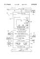
- FIG. 1is a top view of a planting implement (e.g., a 12/23 solid row crop (SRC) cyclo planter);
- a planting implemente.g., a 12/23 solid row crop (SRC) cyclo planter
- FIG. 2ashows single-stage markers in their fully folded and unfolded states
- FIG. 2bshows dual-stage markers in their fully, partially and unfolded states
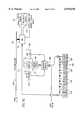
- FIG. 3is a block diagram of the control system for an agricultural work vehicle and planting implement which includes a vehicle data bus and an implement data bus;
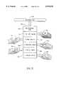
- FIG. 4is a block diagram of the cab display unit (CDU) of FIG. 3, and the interfaces between the CDU and other components of the control system;
- CDUcab display unit
- FIG. 5is a block diagram of the monitor interface unit (MIU) of FIG. 3, and the interfaces between the MIU and other components of the control system;
- MIUmonitor interface unit
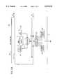
- FIG. 6is a block diagram of a control system for a planter (e.g., 12/23 SRC cyclo planter) including an MIU for monitoring sensors and controlling global functions;
- a plantere.g., 12/23 SRC cyclo planter
- MIUfor monitoring sensors and controlling global functions
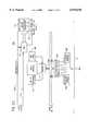
- FIG. 7is an electrical block diagram showing the MIU and the interfaces between the MIU and the lighting, frame and marker systems of the planter in FIG. 6;
- FIG. 8is a hydraulic schematic showing interfaces between the hydraulic valves and cylinders of the frame and marker control systems of the planter in FIG. 6;
- FIG. 9is a block diagram of a control system for a conventional drill (e.g., a soybean special grain drill) including an MIU for monitoring sensors and controlling global functions;
- a conventional drille.g., a soybean special grain drill
- MIUfor monitoring sensors and controlling global functions
- FIG. 10is an electrical block diagram showing the MIU and the interfaces between the MIU and the lighting, frame and marker systems of the drill shown in FIG. 9;
- FIG. 11is a block diagram of a control system for an air drill (e.g., Concord air drill) including an MIU for monitoring sensors and controlling global functions;
- an air drille.g., Concord air drill
- MIUfor monitoring sensors and controlling global functions
- FIG. 12is an electrical block diagram showing the MIU and the interfaces between the MIU and the lighting, frame and marker systems of the drill shown in FIG. 11;
- FIG. 13is a block diagram of one multi-channel controller (MCC) of FIG. 3, and the interfaces between the MCC and other components of the control system;
- MCCmulti-channel controller
- FIG. 14is a block diagram of a control system for a planter as in FIG. 6 which further includes local MCCs to control the seed rates of each section;
- FIG. 15is an electrical block diagram showing the MCC and interfaces between the MCC and metering systems (seed, chemical, fertilizer) of the planter in FIG. 14;
- FIG. 16is a hydraulic schematic showing interfaces between the hydraulic valves and motors (seed, blower, chemical, fertilizer) of the planter shown in FIG. 14;
- FIG. 17is a block diagram of a control system for a conventional drill as in FIG. 9 which further includes local MCCs to control the seed rates of each section;
- FIG. 18is an electrical block diagram showing the MCC and the interfaces between the MCC and the metering systems (bins 1 and 2) of the drill shown in FIG. 17;
- FIG. 19is a block diagram of a control system for an air drill as in FIG. 11 (e.g., Concord air drill) further including a local MCC to control the seed rates of the implement sections; and
- an air drillas in FIG. 11 (e.g., Concord air drill) further including a local MCC to control the seed rates of the implement sections; and
- FIG. 20is an electrical block diagram showing the MCC and the interfaces between the MCC and the metering systems (bins 1-3 and anhydrous) of the drill of FIG. 19 (e.g., Concord air drill).
- the drill of FIG. 19e.g., Concord air drill.
- a planting implement 10(e.g., 12/23 SRC cyclo planter) is shown.
- Implement 10includes a frame 12, row units 14 mounted beneath frame 12, and seed modules 16 supported on frame 12.
- Frame 12includes a middle section 18, two wing sections 20 mounted for rotation on either side of section 18, and a drawbar 22 extending forward from section 18.
- Wing sections 20are horizontally rotatable in towards drawbar 22 to decrease implement width for transport.
- An eye 24extends from drawbar 22 for connection to a vehicle.
- Each seed module 16meters seeds for one section.
- the sectionsinclude 8, 8 and 7 row units 14, respectively.
- the metered seedstravel through seed tubes (not shown) to row units 14.
- Implement 10also supports bins 25 storing other products (e.g., fertilizer) along with metering devices therefore.
- FIGS. 1 and 2markers attached to ends 26 of wing sections 20 on both sides of frame 12 are used to mark the centerline of the next pass through a field.
- a particular implementmay use single-stage markers 50 (FIG. 2a).
- FIG. 2ashows single stage marker 50 in its fully folded and unfolded states.
- Marker 50includes a pivot assembly 52 mounted to end 26 of wing section 20 and a marker rod 54 connected between assembly 52 and a disk 56. Disk 56 marks the field when marker 50 is unfolded.
- Marker 50is actuated by an outer cylinder assembly 58 pivotally coupled between a support member 60 extending from end 26 and a bracket 62 attached to rod 54. Marker 50 is folded when cylinder assembly 58 is extended and unfolded when assembly 58 is retracted.
- dual-stage marker 52is shown in its fully, partially, and unfolded states.
- Marker 52includes a first pivot assembly 64 mounted to end 26 of wing section 20, a second pivot assembly 66, and a first marker rod 68 connected between assemblies 64 and 66.
- a second marker rod 70is connected between assembly 66 and a marker disk 72.
- Disk 72marks the field when marker 52 is unfolded.
- Marker 52is actuated by inner and outer cylinder assemblies 74 and 76.
- Assembly 74is pivotally coupled between a first support member 78 extending from end 26 and second support member 80 attached to assembly 66.
- Assembly 76is pivotally coupled between member 80 and a bracket 82 attached to rod 70.
- Marker 52is folded when assemblies 74 and 76 are extended, partially folded with assembly 74 retracted and assembly 76 extended, and unfolded with assemblies 74 and 76 retracted.
- System 100includes electronic control units (ECUs) in communication with each other across a vehicle data bus 104.
- Bus 104includes a tractor bus segment 106 to pass data throughout vehicle 102, and an implement bus segment 108 to communicate between vehicle 102 and implement 10.
- Bidirectional datapasses between busses 106 and 108 via a network interconnection ECU 110 (e.g., a gateway).
- Bus 104preferably conforms to the "Recommended Practice for a Serial Control and Communications Vehicle Network" (SAE J-1939) which uses Controller Area Network (CAN) protocol for low-layer communications.
- SAE J-1939Serial Control and Communications Vehicle Network
- CANController Area Network
- ECU 110performs network functions as described in the Network Layer specification of J-1939 by acting as a repeater for forwarding messages between segments 106 and 108, a bridge for filtering out messages not needed by the receiving segment, a message router for remapping addresses and a gateway to repackage messages for increased efficiency.
- Other bus formatsmay also be used and ECU 110 may perform all or only a subset of the above-listed network functions.
- ECUs coupled to tractor bus 106include an armrest control unit (ARU) 112, instrument cluster unit (ICU) 114, auxiliary valve control unit (AUX) 116, electronic draft control unit (EDC) 118, transmission control unit (TCU) 120, power take-off control unit (PTO) 122, and engine governor control unit (GOV) 124.
- ICU 114receives signals from a true ground speed sensor 126 (e.g., a radar) mounted to the body of vehicle 102.
- Ground speed sensor 126e.g., a radar
- CDUcab-mounted display unit
- a service tool 130can be coupled to busses 106 and 108 via a diagnostic connector 132 for use during diagnostics and maintenance.
- the ECUs coupled to tractor bus 106are illustrative and other control units such as a performance monitor control unit or steering control unit could also be connected to bus 106. Further, the use of gateway 110 for communications between busses 106 and 108 allows a higher level of integration in tractors equipped with a tractor data bus. However, implement bus 108 and its associated ECUs may also be used to control implements pulled by other tractors which have no tractor data bus.
- Implement bus 108includes first and second segments 134 and 136 coupled via a connector 138 at the rear of vehicle 102. Segment 134 passes through vehicle 102 and segment 136 provides a communication pathway to implement 10. Thus, implement bus 108 reduces wiring needs between implement 10 and vehicle 102.
- ECUs coupled to segment 134include cab-mounted display unit (CDU) 140.
- CDU 140provides an operator interface, a serial interface (e.g., RS-232) to receive positioning signals from a DGPS receiver 142, and an interface for a memory card 144 (e.g., a PCMCIA card).
- Receiver 142receives GPS and DGPS signals from antennas 146 and 148.
- Memory card 144transfers geo-referenced map data (e.g., prescription and application rate maps defined by GIS or Global Information System databases) between control system 100 and an external computer 150.
- Prescription mapsinclude application rate commands, and application rate maps record actual (i.e., sensed) application rates.
- ECUs coupled to segment 136 of implement bus 108are mounted to frame 12 of implement 10. These ECUs include a monitor interface unit (MIU) 152 and one or more multi-channel control units (MCCs) 154. Each implement section typically includes one "local" MCC 154 to control product application rates. MIU 152 monitors application rates of products (e.g., seeds) to rows and other parameters (e.g., bin level, ground speed, wheel speed, meter pressure) based on signals generated by monitoring sensors 156, implement status devices 158 and a wheel speed sensor 128 (e.g., inductance magnetic pickup sensor) coupled to the vehicle's wheels.
- productse.g., seeds
- other parameterse.g., bin level, ground speed, wheel speed, meter pressure
- MIU 152also receives global commands from CDU 140 via bus 108, generates global control signals using the global commands, and applies the global control signals to global output devices 160 to perform global implement functions (e.g., lighting, frame, marker control).
- MCCs 154receive local product application rate commands from CDU 140 based on signals generated by application sensors 161, generate local control signals for local product metering devices 162, and apply the local control signals to metering devices 162. Further, MCCs 154 may generate control signals for a variety or type switch 164 which selects the variety or type of farming inputs applied. MCCs 154 may also generate control signals for a section control switch 165 which selects which sections are enabled or disabled.
- CDU 140is an ECU mounted in the cab of vehicle 102.
- CDU 140includes a display unit 200 including a touch screen 202 (e.g., a TFT 10.4" color display with digital touch screen), system touch screen switches 204, reconfigurable touch screen switches 206 and system reset switch 208.
- a 1/2 VGA monochrome DMTN display with LED backlightingcould also be used.
- CDU 140has interfaces 210-224 for implement bus 108, a remote keypad 226, DGPS receiver 142, digital inputs (e.g., an in-cab remote switch 228), frequency inputs such as radar 126, memory card 144 and tractor bus 106.
- CDU 140includes an audible alarm 230.
- a processore.g., ARM LH74610 RISC processor coupled to memory circuits (e.g., RAM, EEPROM, Flash EPROM) provides control for CDU 140.
- Control system 100can control different planting implement applications.
- An operatoruses touch screen 202 to navigate and perform common functions within each application.
- System touch screen switches 204include a MODE switch for toggling between applications, a CALIBRATE switch for performing configuration and calibration functions, and a UTILITY switch for performing file transfers on card 144.
- Touch screen switches 206select between items on reconfigurable menus to control the operations of control system 100.
- Reset switch 208resets control system 100.
- In-cab remote switch 228allows the operator to remotely start and stop product metering.
- Alarm 230is used to alert the operator to error and alarm conditions.
- Both global and local operations of implement 10are controlled by actuations of touch screen switches 204-206.
- the global functionsinclude lighting control (e.g., turning on and off lights attached to frame 12), frame control (e.g., raising and lowering frame 12; folding and unfolding wings 20) and marker control (e.g., alternately raising and lowering markers 50 or 52 on both sides of implement 10 to mark the centerline of the next pass). Actuations needed to control the global functions depend on the particular implement.
- CDU 140When switch actuations relate to lighting, frame or marker control, CDU 140 generates global command signals which are communicated to MIU 152 via bus 108 for controlling global output devices 160.
- the local implement functionsinclude variable-rate application of products to a field.
- Touch screen switches 204-206are actuated to control the rates in a manual or an automatic mode.
- the actuationsset, increase or decrease the desired application rates for one or more products applied by each section.
- the actuationsselect between one or more prescription maps stored on card 144.
- the mapsinclude geo-referenced data representing desired application rates of one or more products at positions throughout a field. Desired rates are determined, for example, off-line using computer 150.
- the selected mapsare indexed using positioning signals received by DGPS receiver 142 to determine the desired application rates which are then used to generate local product rate commands transmitted to MCCs 154.
- MIU 152is an ECU supported on frame 12 which includes interfaces 250-262 for implement bus 108, frame/marker outputs 264 (e.g., markers 50, 52; wings 20), lighting outputs 266, frequency inputs 268, digital inputs 270, analog inputs 272 and sensor bus 274. Interfaces 250-262 include spares such that MIU 152 can be used in multiple applications.
- MIU 152is connected in control system 100 as shown below.
- Sensor bus 274is coupled to seed rate sensors 276, a blockage module 278 coupled to blockage sensors 280, and a gateway module 282.
- Optical seed rate sensors 276detect seeds passing through seed tubes to row units 14.
- Module 282receives signals from optical bin level sensors 284, a meter speed sensor 286, and bin pressure or material flow sensor 288 or 290. Signals from bin level sensors 284 indicate when the bins of seed modules 16 are 75% full, 50% full, 25% full, and Empty.
- Sensor bus 274is preferably an RS-485 network as described in U.S. Pat. No. 5,635,911, herein incorporated by reference.
- MIU 152is controlled by a processor 314 (FIG. 7; e.g., an AN8OC196CB processor) coupled to memory (e.g., RAM, EEPROM, Flash EPROM).
- Control system 100is a modular application control system which can be upgraded with additional controllers for expanded functionality.
- control system 100includes CDU 140, implement bus 108 and MIU 152 which provide monitoring and global control functions.
- product application ratesare controlled conventionally (e.g., by driving product metering devices using gears coupled to the implement wheels).
- FIGS. 6-12show control system 100 in embodiments which provide for monitoring and global control functions for implements.
- Control system 100can later be upgraded with MCCs 154 to provide variable-rate control.
- FIGS. 14-20show upgraded control system 100 for the same implements.
- control system 100controls a 12/23 SRC cyclo planter implement 10 which includes three sections 300, each supporting multiple (e.g., 8, 8 and 7) row units 14 configured to apply seeds to a field. Seeds are metered by a seed module 16 on each section 300.
- MIU 152receives global command signals via bus 108 from CDU 140, and sends back monitored data.
- MIU 152receives speed signals used to calculate seeding data (e.g., area seeded) from a sensor 302 coupled to the planter wheels.
- MIU 152receives signals indicating whether implement 10 is up or down from a status sensor 304. The application of products is disabled when implement 10 is raised.
- Sensor bus 274is connected to a seed rate sensor 276 associated with each row unit 14.
- MIU 152monitors seed application rates using signals received from seed rate sensors 276, and sends seed rate data to CDU 140 via bus 108.
- Bus 274is coupled to a gateway module 282 for each section 300 which monitors the status of each seed module 16 using signals received from bin level sensors 284, meter speed sensor 286, and bin pressure sensor 288.
- MIU 152transmits meter status to CDU 140. Connectors separate MIU 152, sensors 276 and gateway modules 282.
- MIU 152controls the planter's lighting, frame and marker systems.
- the lighting system commandsinclude right turn, left turn, and tail lamp signals received on conductors 306-310 from a connector 312 at the rear of vehicle 102.
- Processor 314reads the signals on conductors 306-310, converts these standard signals to enhanced lighting commands based on the ASAE S279 standard, and applies these commands to drivers 254 to generate enhanced control signals applied to left and right enhanced signal lamps including turn/flash lamps 316, tail lamps 318, and enhanced turn lamps 320.
- Lamps 316-320enhance the turn signals warning motorists that vehicle 102 and implement 10 are turning. In contrast to current turn signal lamps, neither of the enhanced lamps will flash when implement 10 is in transport mode only. Additionally, the opposite turn signal lamp will not light steadily when making a turn.
- the lighting system of MIU 152allows an implement which is compatible with the enhanced lighting standard to be connected directly to connector 312 of existing tractors.
- Circuit 322includes valve coils which control the flow of hydraulic fluid to actuators which move frame members such as wings 20.
- the coilsinclude left and right tuck wheel solenoids 324, raise limit solenoids 326, marker isolation solenoids 328, and slave return solenoids 330.
- Circuit 322uses relay circuits 332-338 to apply power simultaneously to each pair (left and right) of solenoids 324-330.
- Processor 314also receives commands for the marker control system from CDU 140 via bus 108. Based upon the commands, processor 314 commands drivers 252 to generate marker control signals applied to a marker circuit 342.
- Circuit 342includes coils which control fluid applied to marker actuators. The coils include left and right inner and outer marker solenoids 344 and 346 turned on and off by grounding the low-sides, thereby selectively supplying hydraulic fluid to the marker actuators as shown below.
- frame solenoids 324-328, 340 and marker solenoids 344-346control the flow of fluid through hydraulic cartridge valves 348-360, respectively.
- Implement 10includes, for example, left and right wing wheels (LWW, RWW), left and right center wheels (LCW, RCW), and left and right inner wheels (LIW, RIW).
- Fluid from tuck valves 348is supplied to left and right wing wheels (LWW, RWW), and is cross-linked to the right and left center wheels (RCWX, LCWX).
- Fluid from raise limit and marker/isolation valves 350 and 352is supplied to the left and right center and inner wheels (LCW, RCW, LIW and RIW).
- Fluid from fold valve 356is supplied to left and right fold members (LWF, RWF).
- Fluid from inner and outer marker valves 358 and 360is supplied to left and right outer and inner markers (LOM, ROM, LIM, RIM).
- Fluid from tuck valves 348is received by the piston end of first slave cylinders 368, passed from the rod end of cylinders 368 to the piston of second slave cylinders 370, and returned via slave return valves 354 from the rod end of cylinders 370 to return line 366.
- Fluid from raise limit and marker/isolation valves 350 and 352, which check flow in opposite directions,is received by piston ends of master and assist cylinders 372 and 374. Fluid from the rod end of master cylinders 372 crosses to the piston end of opposite slave cylinders 368 and fluid from the rod end of cylinders 370 returns on line 366.
- master cylinders 372are connected in master-slave arrangements to opposite slave cylinders 368 and 370 to coordinate movement of center and wing wheels LCW, RCW, LWW, RWW such that each pair of wheels extends the same amount, thereby evenly raising and lowering implement 10.
- Master cylinders 372, slave cylinders 368 and 370, and assist cylinders 374form a lift circuit. Fluid from fold valve 356 is received by the piston end of fold cylinders 376 and is returned to return line 366. Fluid from marker valves 358 and 360 is received by the piston end of outer and inner marker cylinders 74 and 76, and returned from the rod end of cylinders 74 to line 366.
- tuck and slave return solenoids 324 and 330control the flow to slave cylinders 368 and 370 to tuck wing wheels LWW and RWW.
- Energizing solenoids 324 and 330causes fluid to flow from supply line 364 through tuck valves 348 to slave cylinders 368 and 370 and through slave return valves 354 to line 366. This flow extends cylinders 368 and 370 to tuck the wing wheels during transport.
- slave return solenoids 330are de-energized to prevent fluid loss and to prevent the wheels from sagging down.
- raise limit solenoids 326shut off the flow to the lift circuit including cylinders 368-374 to prevent implement 10 from being raised higher. Because raise limit valves 350 check flow in only one direction, implement 10 can still be lowered while solenoids 326 remain energized.
- Markers 52are controlled to indicate the centerline of the next implement pass. Marker status is displayed on display unit 200 of CDU 140. For example, an icon for each marker 52 indicates whether the marker is active or inactive. Touching the inactive marker's icon causes CDU 140 to communicate a message to MIU 152 to cause MIU 152 to advance markers 52. Markers 52 can also be advanced automatically by alternating from left to right with each raise/lower cycle of implement 10 based upon the implement status input 304.
- Single-stage markers 50move to fully-folded states during transport, and alternate between fully-folded and unfolded states for field operations. Dual-stage markers 52 move to fully folded states for transport, and alternate between partially folded and unfolded states during operations.
- control system 100is configured to control a conventional 5500 Soybean Special grain drill including two sections 300.
- Each section 300supports multiple (e.g., 12 and 12) row units 14 configured to apply seeds to a field. Seeds are metered by a seed module 16 on each section 300.
- MIU 152receives global command signals from CDU 140, and returns monitored data.
- MIU 152receives speed signals used to calculate seeding data from sensor 302 coupled to the drill's wheels, and receives signals indicating whether implement 10 is up or down from sensor 304. Application of products is disabled when implement 10 is raised.
- Sensor bus 274connects to a seed rate sensor 276 associated with each row unit 14.
- MIU 152monitors seed application rates using signals received from sensors 276, and sends seed rate data to CDU 140.
- Bus 274is also coupled to bin level gateway modules 305 which monitor and receive bin level signals from bin level sensors 284 on each section 300. Bin status data is transmitted to CDU 140 and connectors separate MIU 152 and sensors 276 and 284.
- MIU 152controls the lighting, frame and marker systems of the conventional grain drill.
- the lighting control systemis as described in relation to FIG. 7.
- the frame control systemincludes a solenoid circuit 400 including coils controlling fluid applied to frame actuators.
- the coilsinclude a fold lock solenoid (lower) 402, left-hand gauge cylinder solenoids (lower, raise) 404 and 406, right-hand gauge cylinder solenoids (raise, lower) 408 and 410, cart and gauge cylinder solenoids (lower) 412 and 414, and relays 416 and 418 for applying power to electric clutches 420 and 422 for two bins.
- the marker control systemhas a marker circuit 424 with left and right marker solenoids 344 for controlling single-stage markers 50.
- Frame and marker control system commandsare received by MIU 152 from CDU 140, and are used to generate frame and marker control signals which are applied to circuits 400 and 424 by drivers 252.
- control system 100is configured to control a Concord air drill including six sections 300. Each section 300 supports a blockage module 278 coupled to 12 blockage sensors 280. Seeds are metered by a seed or seed/fertilization module 16 or 426 for each section 300.
- MIU 152receives global command signals from CDU 140 and returns monitored data. MIU 152 receives speed signals used to calculate seeding data from wheel speed sensor 302. MIU 152 also receives signals indicating whether implement 10 is up or down from sensor 304, and wheel speed signals from wheel speed sensor 302. Product application is disabled with implement 10 raised.
- Sensor bus 274is connected to a blockage module 278 associated with each section 300.
- MIU 152monitors seed blockages based on signals received from modules 278, and sends blockage data to CDU 140 via bus 108.
- Bus 274is also coupled to a gateway module 282 on each section 300 which receives product meter status signals from bin level sensors 284 and meter blockage sensors 290. Meter status data is transmitted back to CDU 140 via bus 108.
- MIU 152controls the lighting, frame and marker systems of the Concord air drill.
- the lighting and marker control systemsare as described in relation to FIGS. 7 and 10.
- the frame control systemincludes a solenoid circuit 432 with coils controlling the fluid applied to frame actuators.
- the coilsinclude relays 434-440 to apply power to a main electric clutch 442 and clutches 444-448 coupled to three product bins.
- Control system 100may be upgraded by installing a removable MCC 154 on each frame section 300 to provide local variable-rate control.
- each MCC 154includes interfaces 500-510 for implement bus 108, on/off outputs 512 for driving valves, PWM outputs 514 for driving local product metering devices, frequency inputs 516, digital inputs 518, and analog inputs 520. Spare interfaces allow MCC 154 to be used in multiple applications. Connections between MCC 154 and control system 100 are shown below.
- MCC 154is controlled by a processor 522 (FIG. 15; e.g., AN80C196CB) coupled to memory circuits (e.g., RAM, EEPROM, Flash EPROM).
- control system 100also controls the cyclo planter.
- MCCs 154control the seed application rates of each section 300 based on rate command signals received from CDU 140 via bus 108.
- Each MCC 154converts the rate command signals into control signals which are applied to a cyclo seed meter 522 (i.e., drum) on seed module 16.
- MCC 154receives meter feedback speed signals from meter 522, and communicates meter speed data back to CDU 140 for display.
- MCC 154can also use the meter speed feedback signals for closed-loop metering control.
- Each MCC 154also applies control signals to bin pressure or material flow sensor 288, receives pressure feedback signals from sensor 288, and communicates bin pressure data back to CDU 140 for display.
- each local MCC 154controls product application rates for one section of implement 10.
- the controlled productsmay include seeds, granular chemicals and liquid fertilizers.
- Commands for each product being appliedare received by MCC processor 524 from CDU 140.
- Processor 524commands drivers 504 to generate PWM control signals based on the commands which are applied to a cyclo seed meter solenoid 526, a blower motor solenoid 528, a chemical meter solenoid 530 and a liquid fertilizer meter solenoid 532.
- Feedback signalsare received from a cyclo seed meter speed sensor 534, a cyclo meter pressure sensor 536, a chemical meter speed sensor 538, and a fertilizer meter speed sensor 540.
- Processor 524may also control the variety of seeds being applied by generating variety control signals based upon command signals received from CDU 140.
- the control signalsare applied to a relay circuit 542 which applies power to a variety selection switch 544 to select between two varieties of seeds.
- Processor 524further controls a relay circuit 546 configured to open and shut a liquid fertilizer control valve for the local section 300.
- solenoids 526-532control the flow of fluid from a pressurized hydraulic fluid source 548 through valves 550-556 to a seed drum motor 558, a blower motor 560, chemical motors 562 and a fertilizer motor 564. These motors control the seeding rate, fan speed, and chemical and fertilizer application rates.
- control system 100controls a conventional drill.
- MCCs 154control the rates at which seeds are applied by the sections 300 using seed rate command signals received from CDU 140.
- Each MCC 154converts the rate command signals into rate control signals which are applied to a seed meter 522 on each seed module 16.
- MCCs 154receive feedback speed signals from meter 522, and communicate meter speed data back to CDU 140 for display. MCCs 154 can also use the speed feedback signals for closed-loop metering control.
- each local MCC 154controls product application rates for one section 300 of the conventional drill.
- Commands for each product being appliedare received by MCC processor 524 from CDU 140.
- drivers 504are commanded to generate PWM control signals which are applied to metering device solenoids 566 and 568 for bins 1 and 2.
- Solenoids 566 and 568control valves configured to supply fluid to hydraulic motors which dispense seeds from bins.
- Feedback signalsare received from bin 1 and bin 2 meter speed sensors 570 and 572. These signals are sent to CDU 140 for display, or can be used for closed-loop control.
- control system 100is configured to control a Concord air drill.
- a local MCC 154controls the seed application rates of the implement's six sections 300 based upon seed rate command signals received from CDU 140.
- MCC 154converts the rate command signals into control signals applied to meter 522 on seed module 16 or seed/fertilizer module 426.
- MCC 154receives feedback speed signals from meter 522, and sends meter speed data back to CDU 140 for display. Feedback signals may also be used for closed-loop control.
- MCC 154also applies control signals to fan speed sensor 428, receives speed feedback signals from sensor 428, and communicates fan speed data back to CDU 140 for display.
- MCC processor 524when installed, local MCC 154 controls the product application rates for the air drill.
- Commands for each product being appliedare received by MCC processor 524 from CDU 140.
- Processor 524commands drivers 504 based on the commands to generate PWM control signals applied to bin 1, bin 2 and bin 3 metering device solenoids 574-578.
- Solenoids 574-578control hydraulic valves configured to supply fluid to motors to dispense seeds or seeds/fertilizer from bins.
- Feedback signalsare received from bin 1, 2 and 3 meter speed sensors 580-584.
- Processor 524further controls a relay circuit 584 which applies power to an anhydrous control valve.
- An H-bridge driver 586drives an anhydrous flow control valve 588, and feedback signals are provided by a sensor 590.
- a switch 592is provided to turn on and off the flow.
Landscapes
- Life Sciences & Earth Sciences (AREA)
- Engineering & Computer Science (AREA)
- Soil Sciences (AREA)
- Physics & Mathematics (AREA)
- Environmental Sciences (AREA)
- General Physics & Mathematics (AREA)
- Data Mining & Analysis (AREA)
- Mathematical Physics (AREA)
- Pure & Applied Mathematics (AREA)
- Theoretical Computer Science (AREA)
- Mathematical Optimization (AREA)
- Computational Mathematics (AREA)
- Mathematical Analysis (AREA)
- Zoology (AREA)
- Mechanical Engineering (AREA)
- Algebra (AREA)
- Wood Science & Technology (AREA)
- Pest Control & Pesticides (AREA)
- Databases & Information Systems (AREA)
- Software Systems (AREA)
- General Engineering & Computer Science (AREA)
- Insects & Arthropods (AREA)
- Sowing (AREA)
Abstract
Description
Claims (20)
Priority Applications (2)
| Application Number | Priority Date | Filing Date | Title |
|---|---|---|---|
| US08/935,411US6070538A (en) | 1996-11-22 | 1997-09-23 | Modular agricultural implement control system |
| CA002247788ACA2247788C (en) | 1997-09-23 | 1998-09-22 | Modular agricultural implement control system |
Applications Claiming Priority (2)
| Application Number | Priority Date | Filing Date | Title |
|---|---|---|---|
| US08/753,335US5878371A (en) | 1996-11-22 | 1996-11-22 | Method and apparatus for synthesizing site-specific farming data |
| US08/935,411US6070538A (en) | 1996-11-22 | 1997-09-23 | Modular agricultural implement control system |
Related Parent Applications (1)
| Application Number | Title | Priority Date | Filing Date |
|---|---|---|---|
| US08/753,335Continuation-In-PartUS5878371A (en) | 1996-11-22 | 1996-11-22 | Method and apparatus for synthesizing site-specific farming data |
Publications (1)
| Publication Number | Publication Date |
|---|---|
| US6070538Atrue US6070538A (en) | 2000-06-06 |
Family
ID=46203211
Family Applications (1)
| Application Number | Title | Priority Date | Filing Date |
|---|---|---|---|
| US08/935,411Expired - LifetimeUS6070538A (en) | 1996-11-22 | 1997-09-23 | Modular agricultural implement control system |
Country Status (1)
| Country | Link |
|---|---|
| US (1) | US6070538A (en) |
Cited By (86)
| Publication number | Priority date | Publication date | Assignee | Title |
|---|---|---|---|---|
| US6223110B1 (en)* | 1997-12-19 | 2001-04-24 | Carnegie Mellon University | Software architecture for autonomous earthmoving machinery |
| US20020065594A1 (en)* | 1999-07-30 | 2002-05-30 | Oshkosh Truck Corporation | Military vehicle having cooperative control network with distributed I/O interfacing |
| US20030001751A1 (en)* | 2000-11-17 | 2003-01-02 | Hiroshi Ogura | Display device and display controller of construction machinery |
| US6516271B2 (en) | 2001-06-29 | 2003-02-04 | The Regents Of The University Of California | Method and apparatus for ultra precise GPS-based mapping of seeds or vegetation during planting |
| US6553312B2 (en) | 2001-06-29 | 2003-04-22 | The Regents Of The University Of California | Method and apparatus for ultra precise GPS-based mapping of seeds or vegetation during planting |
| US6564915B2 (en)* | 2001-08-10 | 2003-05-20 | Caterpillar Inc | Power take-off clutch control system |
| US6584920B1 (en)* | 2002-09-17 | 2003-07-01 | Bourgault Industries Ltd. | System and method for adjusting air flow in air seeding applications |
| US20030158635A1 (en)* | 1999-07-30 | 2003-08-21 | Oshkosh Truck Corporation | Firefighting vehicle with network-assisted scene management |
| US20030200015A1 (en)* | 2000-02-09 | 2003-10-23 | Oshkosh Truck Corporation | Equipment service vehicle having on-board diagnostic system |
| US20040039510A1 (en)* | 1999-07-30 | 2004-02-26 | Oshkosh Truck Corporation | Control system and method for an equipment service vehicle |
| US20040133319A1 (en)* | 1999-07-30 | 2004-07-08 | Oshkosh Truck Corporation | User interface and method for vehicle control system |
| US6786143B2 (en)* | 2000-06-29 | 2004-09-07 | New Holland North America, Inc. | Baler control system |
| US20040199302A1 (en)* | 2001-12-21 | 2004-10-07 | Oshkosh Truck Corporation | Turret control system and method for a fire fighting vehicle |
| US6810315B2 (en)* | 2001-11-21 | 2004-10-26 | Pgi International, Ltd. | Agricultural vehicle dispenser regulator and method |
| US20040244659A1 (en)* | 2003-06-03 | 2004-12-09 | Dean Mayerle | Variable rate meter drive system |
| US20050004733A1 (en)* | 1999-07-30 | 2005-01-06 | Oshkosh Truck Corporation | Concrete placement vehicle control system and method |
| US20050099550A1 (en)* | 2003-09-30 | 2005-05-12 | Yushi Jinno | Semiconductor device and display device |
| US20050113996A1 (en)* | 2001-12-21 | 2005-05-26 | Oshkosh Truck Corporation | Ambulance control system and method |
| US20050114007A1 (en)* | 2001-12-21 | 2005-05-26 | Oshkosh Truck Corporation | Multi-network control system for a vehicle |
| AU2002300913B2 (en)* | 2002-08-14 | 2005-06-02 | Bourgault Industries Ltd | System and method for adjusting air flow in air seeding applications |
| US20050131600A1 (en)* | 2001-12-21 | 2005-06-16 | Oshkosh Truck Corporation | Control system and method for a concrete vehicle |
| US20050209747A1 (en)* | 2001-01-31 | 2005-09-22 | Oshkosh Truck Corporation | Control system and method for electric vehicle |
| US20050234622A1 (en)* | 2002-06-13 | 2005-10-20 | Oshkosh Truck Corporation | Steering control system and method |
| US20060026101A1 (en)* | 2003-06-19 | 2006-02-02 | Hiroshi Ogura | Work support and management system for working machine |
| US7184862B2 (en) | 1999-07-30 | 2007-02-27 | Oshkosh Truck Corporation | Turret targeting system and method for a fire fighting vehicle |
| CN1326442C (en)* | 2005-06-21 | 2007-07-18 | 吉林大学 | Virtual GPS accurate agricultural variable subsoil application system |
| US20070173987A1 (en)* | 1999-07-30 | 2007-07-26 | Oshkosh Truck Corporation | Control system and method for an equipment service vehicle |
| US7302320B2 (en) | 2001-12-21 | 2007-11-27 | Oshkosh Truck Corporation | Failure mode operation for an electric vehicle |
| US20080047475A1 (en)* | 2006-08-22 | 2008-02-28 | Sam Stehling | Custom planter and method of custom planting |
| US20080109131A1 (en)* | 2002-12-09 | 2008-05-08 | Oshkosh Truck Corporation | Refuse vehicle control system and method |
| US7379797B2 (en) | 2001-01-31 | 2008-05-27 | Oshkosh Truck Corporation | System and method for braking in an electric vehicle |
| US20090090284A1 (en)* | 2007-10-09 | 2009-04-09 | Peterson Jr James R | Agricultural seeding system |
| US20090119986A1 (en)* | 2007-11-13 | 2009-05-14 | Pioneer Hi-Bred International, Inc. | High speed seed treatment apparatus |
| US20100010667A1 (en)* | 2007-01-08 | 2010-01-14 | Precision Planting Inc. | Planter monitor system and method |
| US7673572B2 (en) | 2005-05-09 | 2010-03-09 | Monsanto Technology Llc | Custom planter and method of custom planting |
| WO2010056834A1 (en)* | 2008-11-13 | 2010-05-20 | Deere & Company | Seed sensor system and method for improved seed count and seed spacing |
| US7726251B1 (en)* | 2009-03-11 | 2010-06-01 | Deere & Company | Agricultural seeding apparatus and method for seed placement synchronization between multiple rows |
| CN101916075A (en)* | 2010-07-20 | 2010-12-15 | 上海交通大学 | Error Compensation Control System of Fertilizer Discharge Amount of Double-Variable Seeding and Fertilizer Applicator with Opening Degree and Rotating Speed |
| US20110054743A1 (en)* | 2009-08-28 | 2011-03-03 | Kocer Jared E | Multi-variable rate agricultural product application system, device and method |
| CN101715668B (en)* | 2009-12-22 | 2012-05-09 | 中国农业机械化科学研究院 | Seeder, planter sowing monitoring equipment and method |
| CN101547595B (en)* | 2006-08-22 | 2012-11-14 | 孟山都技术有限公司 | Custom planters and methods of custom planting |
| CN103019123A (en)* | 2012-12-26 | 2013-04-03 | 上海大学 | Intelligent control system for cotton picker |
| US20130184944A1 (en)* | 2010-07-14 | 2013-07-18 | Bart M.A. Missotten | Method and device for predictive control of agricultural vehicle systems |
| US20130211628A1 (en)* | 2011-03-11 | 2013-08-15 | Bradley R. Thurow | Vehicle control and gateway module |
| US20140019017A1 (en)* | 2012-07-16 | 2014-01-16 | Claas Selbstfahrende Erntemaschinen Gmbh | Agricultural working machine having at least one control unit |
| WO2014099791A1 (en)* | 2012-12-17 | 2014-06-26 | Precision Planting Llc | Plot placement systems and methods |
| US8893630B2 (en) | 2011-09-29 | 2014-11-25 | Cnh Industrial Canada, Ltd. | System for controlling air flow within an agricultural product metering system |
| US8947531B2 (en) | 2006-06-19 | 2015-02-03 | Oshkosh Corporation | Vehicle diagnostics based on information communicated between vehicles |
| JP2015043763A (en)* | 2013-08-02 | 2015-03-12 | 株式会社Ihiスター | Control device for agricultural machine |
| US20150208571A1 (en)* | 2014-01-24 | 2015-07-30 | Kinze Manufacturing, Inc. | Agricultural implement with electro-hydraulic cylinders |
| US9113591B2 (en) | 2012-06-18 | 2015-08-25 | Raven Industries, Inc. | Implement for adjustably metering an agricultural field input according to different frame sections |
| US9324197B2 (en) | 2011-03-11 | 2016-04-26 | Intelligent Agricultural Soultions | Method and system for managing the hand-off between control terminals |
| US9380773B2 (en) | 2013-03-21 | 2016-07-05 | Raven Industries, Inc. | Gear flow divider for agricultural product injection |
| US9420203B2 (en) | 2006-06-19 | 2016-08-16 | Oshkosh Defense, Llc | Vision system for a vehicle |
| US9474208B2 (en) | 2011-11-15 | 2016-10-25 | Appareo Systems, Llc | System and method for determining material yield and/or loss from a harvesting machine using acoustic sensors |
| US20160316616A1 (en)* | 2015-04-29 | 2016-11-03 | Cnh Industrial America Llc | Operator Selectable Speed Input |
| US9504212B2 (en) | 2013-03-15 | 2016-11-29 | Raven Industries, Inc. | Real time injection for agricultural sprayers |
| US9580256B2 (en) | 2013-03-15 | 2017-02-28 | Raven Industries, Inc. | Granular spreader section control |
| US9629308B2 (en) | 2011-03-11 | 2017-04-25 | Intelligent Agricultural Solutions, Llc | Harvesting machine capable of automatic adjustment |
| US9631964B2 (en) | 2011-03-11 | 2017-04-25 | Intelligent Agricultural Solutions, Llc | Acoustic material flow sensor |
| US9661805B1 (en) | 2015-12-29 | 2017-05-30 | Ball Horticultural Company | Seed sowing system and method of use |
| US9781916B2 (en) | 2013-10-17 | 2017-10-10 | Raven Industries, Inc. | Nozzle control system and method |
| US9845191B2 (en) | 2013-08-02 | 2017-12-19 | Oshkosh Corporation | Ejector track for refuse vehicle |
| US9883626B2 (en)* | 2015-10-02 | 2018-02-06 | Deere & Company | Controlling an agricultural vehicle based on sensed inputs |
| US10085379B2 (en) | 2014-09-12 | 2018-10-02 | Appareo Systems, Llc | Grain quality sensor |
| US10173236B2 (en) | 2013-10-17 | 2019-01-08 | Raven Industries, Inc. | Nozzle control system and method |
| US10318138B2 (en) | 2011-03-11 | 2019-06-11 | Intelligent Agricultural Solutions Llc | Harvesting machine capable of automatic adjustment |
| US10321624B2 (en) | 2011-03-11 | 2019-06-18 | Intelligent Agriculture Solutions LLC | Air seeder manifold system |
| US10375878B2 (en)* | 2017-04-25 | 2019-08-13 | The Climate Corporation | Plot placement systems and methods |
| US20200045879A1 (en)* | 2018-08-09 | 2020-02-13 | Cnh Industrial Canada, Ltd. | System and method for initiating control of components of a work vehicle based on input received from a user interface of an associated agricultural implement |
| US10575459B2 (en) | 2017-07-03 | 2020-03-03 | Cnh Industrial Canada, Ltd. | Product distribution control system for an agricultural system |
| US10737284B2 (en)* | 2017-10-13 | 2020-08-11 | Cnh Industrial America Llc | Tire configuration system for an agricultural machine |
| US10779457B2 (en)* | 2016-10-07 | 2020-09-22 | Agco International Gmbh | Agricultural vehicle having reconfigurable controls |
| US20210062474A1 (en)* | 2019-08-30 | 2021-03-04 | Deere & Company | Supervisory and improvement system for machine control |
| US20210325868A1 (en)* | 2018-08-23 | 2021-10-21 | Precision Planting Llc | Expandable network architecture for communications between machines and implements |
| US11160204B2 (en) | 2013-03-15 | 2021-11-02 | Raven Industries, Inc. | Localized product injection system for an agricultural sprayer |
| US11236841B2 (en) | 2019-10-04 | 2022-02-01 | Raven Industries, Inc. | Valve control system and method |
| US11297753B2 (en) | 2011-04-27 | 2022-04-12 | Kinze Manufacturing, Inc. | Remote adjustment of a row unit of an agricultural device |
| US11612160B2 (en) | 2019-10-04 | 2023-03-28 | Raven Industries, Inc. | Valve control system and method |
| US11744169B2 (en) | 2019-11-14 | 2023-09-05 | Cnh Industrial Canada, Ltd. | Particulate material metering system for an agricultural implement |
| US11744239B2 (en) | 2017-01-05 | 2023-09-05 | Raven Industries, Inc. | Configurable nozzle assembly and methods of same |
| US11765991B2 (en) | 2019-11-14 | 2023-09-26 | Cnh Industrial Canada, Ltd. | Particulate material metering system for an agricultural implement |
| US11805724B2 (en) | 2019-04-17 | 2023-11-07 | Monsanto Technology Llc | Planters for planting seeds in fields, and related methods of planting |
| US12016326B2 (en) | 2017-01-05 | 2024-06-25 | Raven Industries, Inc. | Localized product injection system and methods for same |
| US12268119B2 (en) | 2011-03-10 | 2025-04-08 | Cnh Industrial Canada, Ltd. | Agricultural metering system having multiple meter rollers |
| US12349614B2 (en) | 2021-11-10 | 2025-07-08 | Deere & Company | Air seeding turn compensation using yaw rate from sensor on towing vehicle |
Citations (37)
| Publication number | Priority date | Publication date | Assignee | Title |
|---|---|---|---|---|
| US3762603A (en)* | 1971-07-13 | 1973-10-02 | Int Harvester Co | Seed dispenser for planters |
| US3848552A (en)* | 1971-07-13 | 1974-11-19 | J Bauman | Seed dispenser for planters |
| US3855953A (en)* | 1973-06-18 | 1974-12-24 | Dickey John Corp | Controlled population planter system |
| US3860146A (en)* | 1973-07-09 | 1975-01-14 | Int Harvester Co | Seed dispensing mechanism |
| US3885704A (en)* | 1971-05-24 | 1975-05-27 | Int Harvester Co | Pressure equalizer for pneumatic planter |
| US4013875A (en)* | 1974-01-11 | 1977-03-22 | Mcglynn Daniel R | Vehicle operation control system |
| US4148414A (en)* | 1977-12-01 | 1979-04-10 | Parks Jr Earl R | Row crop planter |
| US4268825A (en)* | 1974-02-06 | 1981-05-19 | Dickey-John Corporation | System for monitoring the movement of objects particularly the feeding of seeds |
| US4296409A (en)* | 1979-03-12 | 1981-10-20 | Dickey-John Corporation | Combine performance monitor |
| US4333096A (en)* | 1979-07-27 | 1982-06-01 | Field Electronics Inc. | Seed planter monitor |
| US4365672A (en)* | 1980-06-05 | 1982-12-28 | International Harvester Co. | Automatic alternating marker system |
| US4381036A (en)* | 1980-06-05 | 1983-04-26 | International Harvester Co. | Planter height and marker control system |
| US4413685A (en)* | 1979-12-11 | 1983-11-08 | Gremelspacher Philip E | Planter implement with adjusting position-display apparatus and system thereof |
| US4467872A (en)* | 1981-11-20 | 1984-08-28 | Hiniker Company | Telescoping row marker |
| US4488476A (en)* | 1982-10-27 | 1984-12-18 | The Cessna Aircraft Company | Marker control valve |
| US4523280A (en)* | 1983-02-24 | 1985-06-11 | Dickey-John Corporation | Spreader control |
| US4530463A (en)* | 1982-08-05 | 1985-07-23 | Hiniker Company | Control method and apparatus for liquid distributor |
| US4653410A (en)* | 1985-03-11 | 1987-03-31 | Typpi Richard M | Seed planter |
| US4721168A (en)* | 1985-09-23 | 1988-01-26 | Kinzenbaw Jon E | Agricultural implement with raisable lift frame rotatable about vertical axis |
| US4747301A (en)* | 1985-04-12 | 1988-05-31 | Massey-Ferguson Services N.V. | Vehicle performance monitoring apparatus |
| US4803626A (en)* | 1987-09-15 | 1989-02-07 | Dickey-John Corporation | Universal controller for material distribution device |
| US5025951A (en)* | 1989-10-31 | 1991-06-25 | Deere & Company | Electronic seed rate system for a grain drill |
| US5220876A (en)* | 1992-06-22 | 1993-06-22 | Ag-Chem Equipment Co., Inc. | Variable rate application system |
| US5232054A (en)* | 1991-12-02 | 1993-08-03 | Great Plains Manufacturing, Incorporated | Front folding no-till drill |
| US5260875A (en)* | 1991-08-20 | 1993-11-09 | Micro-Trak System, Inc. | Networked agricultural monitoring and control system |
| US5323721A (en)* | 1992-03-20 | 1994-06-28 | Micro-Trak Systems, Inc. | Planter monitor system |
| US5424957A (en)* | 1993-10-07 | 1995-06-13 | Info Tech | Accurate metering and control system and method for livestock feeding operation |
| US5431117A (en)* | 1993-08-09 | 1995-07-11 | Triple S Engineering, Inc. | Seed drum row shutoff for planter |
| US5488817A (en)* | 1993-06-28 | 1996-02-06 | Ford New Holland, Inc. | Method and apparatus for the control of self-propelled agricultural harvesting machines |
| US5498929A (en)* | 1995-07-10 | 1996-03-12 | Deere & Company | Vehicle lighting enhancement system |
| US5574657A (en)* | 1994-02-08 | 1996-11-12 | Micro-Trak Systems, Inc. | Electronic rate meter controller and method |
| US5581235A (en)* | 1994-08-11 | 1996-12-03 | Deere & Company | Turn signal control system |
| US5598794A (en)* | 1995-02-13 | 1997-02-04 | Fluid Power Industries, Inc. | High accuracy automatically controlled variable linear seed spacing planting apparatus |
| US5621666A (en)* | 1995-04-20 | 1997-04-15 | Dynavisions, Inc. | Planter monitor |
| US5635911A (en)* | 1995-05-11 | 1997-06-03 | Dickey-John Corporation | Apparatus and method for monitoring an article dispensing device such as a seed planter and the like |
| US5809440A (en)* | 1997-02-27 | 1998-09-15 | Patchen, Inc. | Agricultural implement having multiple agents for mapping fields |
| US5878371A (en)* | 1996-11-22 | 1999-03-02 | Case Corporation | Method and apparatus for synthesizing site-specific farming data |
- 1997
- 1997-09-23USUS08/935,411patent/US6070538A/ennot_activeExpired - Lifetime
Patent Citations (38)
| Publication number | Priority date | Publication date | Assignee | Title |
|---|---|---|---|---|
| US3885704A (en)* | 1971-05-24 | 1975-05-27 | Int Harvester Co | Pressure equalizer for pneumatic planter |
| US3848552A (en)* | 1971-07-13 | 1974-11-19 | J Bauman | Seed dispenser for planters |
| US3762603A (en)* | 1971-07-13 | 1973-10-02 | Int Harvester Co | Seed dispenser for planters |
| US3855953A (en)* | 1973-06-18 | 1974-12-24 | Dickey John Corp | Controlled population planter system |
| US3860146A (en)* | 1973-07-09 | 1975-01-14 | Int Harvester Co | Seed dispensing mechanism |
| US4013875A (en)* | 1974-01-11 | 1977-03-22 | Mcglynn Daniel R | Vehicle operation control system |
| US4268825A (en)* | 1974-02-06 | 1981-05-19 | Dickey-John Corporation | System for monitoring the movement of objects particularly the feeding of seeds |
| US4148414B1 (en)* | 1977-12-01 | 1982-09-21 | ||
| US4148414A (en)* | 1977-12-01 | 1979-04-10 | Parks Jr Earl R | Row crop planter |
| US4296409A (en)* | 1979-03-12 | 1981-10-20 | Dickey-John Corporation | Combine performance monitor |
| US4333096A (en)* | 1979-07-27 | 1982-06-01 | Field Electronics Inc. | Seed planter monitor |
| US4413685A (en)* | 1979-12-11 | 1983-11-08 | Gremelspacher Philip E | Planter implement with adjusting position-display apparatus and system thereof |
| US4365672A (en)* | 1980-06-05 | 1982-12-28 | International Harvester Co. | Automatic alternating marker system |
| US4381036A (en)* | 1980-06-05 | 1983-04-26 | International Harvester Co. | Planter height and marker control system |
| US4467872A (en)* | 1981-11-20 | 1984-08-28 | Hiniker Company | Telescoping row marker |
| US4530463A (en)* | 1982-08-05 | 1985-07-23 | Hiniker Company | Control method and apparatus for liquid distributor |
| US4488476A (en)* | 1982-10-27 | 1984-12-18 | The Cessna Aircraft Company | Marker control valve |
| US4523280A (en)* | 1983-02-24 | 1985-06-11 | Dickey-John Corporation | Spreader control |
| US4653410A (en)* | 1985-03-11 | 1987-03-31 | Typpi Richard M | Seed planter |
| US4747301A (en)* | 1985-04-12 | 1988-05-31 | Massey-Ferguson Services N.V. | Vehicle performance monitoring apparatus |
| US4721168A (en)* | 1985-09-23 | 1988-01-26 | Kinzenbaw Jon E | Agricultural implement with raisable lift frame rotatable about vertical axis |
| US4803626A (en)* | 1987-09-15 | 1989-02-07 | Dickey-John Corporation | Universal controller for material distribution device |
| US5025951A (en)* | 1989-10-31 | 1991-06-25 | Deere & Company | Electronic seed rate system for a grain drill |
| US5260875A (en)* | 1991-08-20 | 1993-11-09 | Micro-Trak System, Inc. | Networked agricultural monitoring and control system |
| US5232054A (en)* | 1991-12-02 | 1993-08-03 | Great Plains Manufacturing, Incorporated | Front folding no-till drill |
| US5323721A (en)* | 1992-03-20 | 1994-06-28 | Micro-Trak Systems, Inc. | Planter monitor system |
| US5220876A (en)* | 1992-06-22 | 1993-06-22 | Ag-Chem Equipment Co., Inc. | Variable rate application system |
| US5488817A (en)* | 1993-06-28 | 1996-02-06 | Ford New Holland, Inc. | Method and apparatus for the control of self-propelled agricultural harvesting machines |
| US5431117A (en)* | 1993-08-09 | 1995-07-11 | Triple S Engineering, Inc. | Seed drum row shutoff for planter |
| US5424957A (en)* | 1993-10-07 | 1995-06-13 | Info Tech | Accurate metering and control system and method for livestock feeding operation |
| US5574657A (en)* | 1994-02-08 | 1996-11-12 | Micro-Trak Systems, Inc. | Electronic rate meter controller and method |
| US5581235A (en)* | 1994-08-11 | 1996-12-03 | Deere & Company | Turn signal control system |
| US5598794A (en)* | 1995-02-13 | 1997-02-04 | Fluid Power Industries, Inc. | High accuracy automatically controlled variable linear seed spacing planting apparatus |
| US5621666A (en)* | 1995-04-20 | 1997-04-15 | Dynavisions, Inc. | Planter monitor |
| US5635911A (en)* | 1995-05-11 | 1997-06-03 | Dickey-John Corporation | Apparatus and method for monitoring an article dispensing device such as a seed planter and the like |
| US5498929A (en)* | 1995-07-10 | 1996-03-12 | Deere & Company | Vehicle lighting enhancement system |
| US5878371A (en)* | 1996-11-22 | 1999-03-02 | Case Corporation | Method and apparatus for synthesizing site-specific farming data |
| US5809440A (en)* | 1997-02-27 | 1998-09-15 | Patchen, Inc. | Agricultural implement having multiple agents for mapping fields |
Non-Patent Citations (5)
| Title |
|---|
| Drills 5400 and 5500 Soybean Special Pamphlet, No. AE 174086, Case Corporation, 1996, 1 page.* |
| Early Riser 955 Series Cyclo Air Planters Pamphlet, No. AE 17086, Case Corporation, 1996, 1 page.* |
| Early Riser Cyclo Air and Plate Planters, RC Cultivators and Hoes Pamphlet, No. AE 101055, Case Corporation, 1995, 2 pages.* |
| Operators Manual, 955 Planter Cyclo Air 12/23 Solid Row Crop Front Fold, Rac 9 29280, Case Corporation, Dec. 1996, 14 excerpts.* |
| Operators Manual, 955 Planter Cyclo Air 12/23 Solid Row Crop Front Fold, Rac 9-29280, Case Corporation, Dec. 1996, 14 excerpts. |
Cited By (143)
| Publication number | Priority date | Publication date | Assignee | Title |
|---|---|---|---|---|
| US6223110B1 (en)* | 1997-12-19 | 2001-04-24 | Carnegie Mellon University | Software architecture for autonomous earthmoving machinery |
| US7729831B2 (en) | 1999-07-30 | 2010-06-01 | Oshkosh Corporation | Concrete placement vehicle control system and method |
| US20070173987A1 (en)* | 1999-07-30 | 2007-07-26 | Oshkosh Truck Corporation | Control system and method for an equipment service vehicle |
| US7024296B2 (en) | 1999-07-30 | 2006-04-04 | Oshkosh Truck Corporation | Control system and method for an equipment service vehicle |
| US7006902B2 (en)* | 1999-07-30 | 2006-02-28 | Oshkosh Truck Corporation | Control system and method for an equipment service vehicle |
| US20080103651A1 (en)* | 1999-07-30 | 2008-05-01 | Oshkosh Truck Corporation | User interface and method for vehicle control system |
| US7715962B2 (en) | 1999-07-30 | 2010-05-11 | Oshkosh Corporation | Control system and method for an equipment service vehicle |
| US20030158635A1 (en)* | 1999-07-30 | 2003-08-21 | Oshkosh Truck Corporation | Firefighting vehicle with network-assisted scene management |
| US7184862B2 (en) | 1999-07-30 | 2007-02-27 | Oshkosh Truck Corporation | Turret targeting system and method for a fire fighting vehicle |
| US20040039510A1 (en)* | 1999-07-30 | 2004-02-26 | Oshkosh Truck Corporation | Control system and method for an equipment service vehicle |
| US20040133319A1 (en)* | 1999-07-30 | 2004-07-08 | Oshkosh Truck Corporation | User interface and method for vehicle control system |
| US7555369B2 (en) | 1999-07-30 | 2009-06-30 | Oshkosh Corporation | Control system and method for an equipment service vehicle |
| US20020065594A1 (en)* | 1999-07-30 | 2002-05-30 | Oshkosh Truck Corporation | Military vehicle having cooperative control network with distributed I/O interfacing |
| US7835838B2 (en) | 1999-07-30 | 2010-11-16 | Oshkosh Corporation | Concrete placement vehicle control system and method |
| US20050004733A1 (en)* | 1999-07-30 | 2005-01-06 | Oshkosh Truck Corporation | Concrete placement vehicle control system and method |
| US7522979B2 (en) | 2000-02-09 | 2009-04-21 | Oshkosh Corporation | Equipment service vehicle having on-board diagnostic system |
| US20030200015A1 (en)* | 2000-02-09 | 2003-10-23 | Oshkosh Truck Corporation | Equipment service vehicle having on-board diagnostic system |
| US6786143B2 (en)* | 2000-06-29 | 2004-09-07 | New Holland North America, Inc. | Baler control system |
| US6766600B2 (en)* | 2000-11-17 | 2004-07-27 | Hitachi Construction Machinery Co., Ltd. | Display device and display controller of construction machinery |
| US20030001751A1 (en)* | 2000-11-17 | 2003-01-02 | Hiroshi Ogura | Display device and display controller of construction machinery |
| US7379797B2 (en) | 2001-01-31 | 2008-05-27 | Oshkosh Truck Corporation | System and method for braking in an electric vehicle |
| US7689332B2 (en) | 2001-01-31 | 2010-03-30 | Oshkosh Corporation | Control system and method for electric vehicle |
| US7848857B2 (en) | 2001-01-31 | 2010-12-07 | Oshkosh Corporation | System and method for braking in an electric vehicle |
| US20050209747A1 (en)* | 2001-01-31 | 2005-09-22 | Oshkosh Truck Corporation | Control system and method for electric vehicle |
| US20080065285A1 (en)* | 2001-01-31 | 2008-03-13 | Oshkosh Truck Corporation | Control system and method for electric vehicle |
| US7711460B2 (en) | 2001-01-31 | 2010-05-04 | Oshkosh Corporation | Control system and method for electric vehicle |
| US7277782B2 (en) | 2001-01-31 | 2007-10-02 | Oshkosh Truck Corporation | Control system and method for electric vehicle |
| US6941225B2 (en) | 2001-06-29 | 2005-09-06 | The Regents Of The University Of California | Method and apparatus for ultra precise GPS-based mapping of seeds or vegetation during planting |
| US6553312B2 (en) | 2001-06-29 | 2003-04-22 | The Regents Of The University Of California | Method and apparatus for ultra precise GPS-based mapping of seeds or vegetation during planting |
| US6516271B2 (en) | 2001-06-29 | 2003-02-04 | The Regents Of The University Of California | Method and apparatus for ultra precise GPS-based mapping of seeds or vegetation during planting |
| US6564915B2 (en)* | 2001-08-10 | 2003-05-20 | Caterpillar Inc | Power take-off clutch control system |
| US6810315B2 (en)* | 2001-11-21 | 2004-10-26 | Pgi International, Ltd. | Agricultural vehicle dispenser regulator and method |
| US20040199302A1 (en)* | 2001-12-21 | 2004-10-07 | Oshkosh Truck Corporation | Turret control system and method for a fire fighting vehicle |
| US7254468B2 (en)* | 2001-12-21 | 2007-08-07 | Oshkosh Truck Corporation | Multi-network control system for a vehicle |
| US7302320B2 (en) | 2001-12-21 | 2007-11-27 | Oshkosh Truck Corporation | Failure mode operation for an electric vehicle |
| US20050113996A1 (en)* | 2001-12-21 | 2005-05-26 | Oshkosh Truck Corporation | Ambulance control system and method |
| US20050114007A1 (en)* | 2001-12-21 | 2005-05-26 | Oshkosh Truck Corporation | Multi-network control system for a vehicle |
| US8000850B2 (en) | 2001-12-21 | 2011-08-16 | Oshkosh Truck Corporation | Failure mode operation for an electric vehicle |
| US7792618B2 (en) | 2001-12-21 | 2010-09-07 | Oshkosh Corporation | Control system and method for a concrete vehicle |
| US7451028B2 (en) | 2001-12-21 | 2008-11-11 | Oshkosh Corporation | Turret control system based on stored position for a fire fighting vehicle |
| US20050131600A1 (en)* | 2001-12-21 | 2005-06-16 | Oshkosh Truck Corporation | Control system and method for a concrete vehicle |
| US20050234622A1 (en)* | 2002-06-13 | 2005-10-20 | Oshkosh Truck Corporation | Steering control system and method |
| US7392122B2 (en) | 2002-06-13 | 2008-06-24 | Oshkosh Truck Corporation | Steering control system and method |
| US20080114513A1 (en)* | 2002-06-13 | 2008-05-15 | Oshkosh Truck Corporation | Steering control system and method |
| US7756621B2 (en) | 2002-06-13 | 2010-07-13 | Oshkosh Corporation | Steering control system and method |
| US7412307B2 (en) | 2002-08-02 | 2008-08-12 | Oshkosh Truck Corporation | Refuse vehicle control system and method |
| AU2002300913B2 (en)* | 2002-08-14 | 2005-06-02 | Bourgault Industries Ltd | System and method for adjusting air flow in air seeding applications |
| US6584920B1 (en)* | 2002-09-17 | 2003-07-01 | Bourgault Industries Ltd. | System and method for adjusting air flow in air seeding applications |
| US7725225B2 (en) | 2002-12-09 | 2010-05-25 | Oshkosh Corporation | Refuse vehicle control system and method with footboard |
| US20080109131A1 (en)* | 2002-12-09 | 2008-05-08 | Oshkosh Truck Corporation | Refuse vehicle control system and method |
| US6851377B2 (en)* | 2003-06-03 | 2005-02-08 | Cnh Canada Ltd. | Variable rate meter drive system |
| US20040244659A1 (en)* | 2003-06-03 | 2004-12-09 | Dean Mayerle | Variable rate meter drive system |
| US7513070B2 (en) | 2003-06-19 | 2009-04-07 | Hitachi Construction Machinery Co., Ltd. | Work support and management system for working machine |
| US20060026101A1 (en)* | 2003-06-19 | 2006-02-02 | Hiroshi Ogura | Work support and management system for working machine |
| US20050099550A1 (en)* | 2003-09-30 | 2005-05-12 | Yushi Jinno | Semiconductor device and display device |
| US7673572B2 (en) | 2005-05-09 | 2010-03-09 | Monsanto Technology Llc | Custom planter and method of custom planting |
| CN1326442C (en)* | 2005-06-21 | 2007-07-18 | 吉林大学 | Virtual GPS accurate agricultural variable subsoil application system |
| US8947531B2 (en) | 2006-06-19 | 2015-02-03 | Oshkosh Corporation | Vehicle diagnostics based on information communicated between vehicles |
| US9420203B2 (en) | 2006-06-19 | 2016-08-16 | Oshkosh Defense, Llc | Vision system for a vehicle |
| CN101547595B (en)* | 2006-08-22 | 2012-11-14 | 孟山都技术有限公司 | Custom planters and methods of custom planting |
| WO2008024760A3 (en)* | 2006-08-22 | 2008-09-25 | Monsanto Technology Llc | Custom planter and method of custom planting |
| US20080047475A1 (en)* | 2006-08-22 | 2008-02-28 | Sam Stehling | Custom planter and method of custom planting |
| US7775167B2 (en) | 2006-08-22 | 2010-08-17 | Monsanto Technology Llc | Custom planter and method of custom planting |
| US8078367B2 (en) | 2007-01-08 | 2011-12-13 | Precision Planting, Inc. | Planter monitor system and method |
| US20100010667A1 (en)* | 2007-01-08 | 2010-01-14 | Precision Planting Inc. | Planter monitor system and method |
| US7717048B2 (en) | 2007-10-09 | 2010-05-18 | Deere & Company | Agricultural seeding system |
| EP2047735A1 (en)* | 2007-10-09 | 2009-04-15 | Deere & Company | Seeding machine and row unit of a seeding machine |
| US20090090284A1 (en)* | 2007-10-09 | 2009-04-09 | Peterson Jr James R | Agricultural seeding system |
| EP2047735B1 (en) | 2007-10-09 | 2015-08-26 | Deere & Company | Seeding machine and row unit of a seeding machine |
| US20090119986A1 (en)* | 2007-11-13 | 2009-05-14 | Pioneer Hi-Bred International, Inc. | High speed seed treatment apparatus |
| US8458953B2 (en)* | 2007-11-13 | 2013-06-11 | Pioneer Hi-Bred International, Inc. | High speed seed treatment apparatus |
| WO2010056834A1 (en)* | 2008-11-13 | 2010-05-20 | Deere & Company | Seed sensor system and method for improved seed count and seed spacing |
| EP2227932A1 (en)* | 2009-03-11 | 2010-09-15 | Deere & Company | Agricultural seeding machine |
| US7726251B1 (en)* | 2009-03-11 | 2010-06-01 | Deere & Company | Agricultural seeding apparatus and method for seed placement synchronization between multiple rows |
| US20110054743A1 (en)* | 2009-08-28 | 2011-03-03 | Kocer Jared E | Multi-variable rate agricultural product application system, device and method |
| US8868300B2 (en) | 2009-08-28 | 2014-10-21 | Raven Industries, Inc. | Multi-variable rate agricultural product application system, device and method |
| CN101715668B (en)* | 2009-12-22 | 2012-05-09 | 中国农业机械化科学研究院 | Seeder, planter sowing monitoring equipment and method |
| US20130184944A1 (en)* | 2010-07-14 | 2013-07-18 | Bart M.A. Missotten | Method and device for predictive control of agricultural vehicle systems |
| US9008918B2 (en)* | 2010-07-14 | 2015-04-14 | Cnh Industrial America Llc | Method and device for predictive control of agricultural vehicle systems |
| CN101916075B (en)* | 2010-07-20 | 2012-07-18 | 上海交通大学 | Fertilizer distributing amount error compensation control system for aperture rotate speed bivariate seeding fertilizer distributor |
| CN101916075A (en)* | 2010-07-20 | 2010-12-15 | 上海交通大学 | Error Compensation Control System of Fertilizer Discharge Amount of Double-Variable Seeding and Fertilizer Applicator with Opening Degree and Rotating Speed |
| US12268119B2 (en) | 2011-03-10 | 2025-04-08 | Cnh Industrial Canada, Ltd. | Agricultural metering system having multiple meter rollers |
| US9330062B2 (en)* | 2011-03-11 | 2016-05-03 | Intelligent Agricultural Solutions, Llc | Vehicle control and gateway module |
| US10321624B2 (en) | 2011-03-11 | 2019-06-18 | Intelligent Agriculture Solutions LLC | Air seeder manifold system |
| US10318138B2 (en) | 2011-03-11 | 2019-06-11 | Intelligent Agricultural Solutions Llc | Harvesting machine capable of automatic adjustment |
| US9631964B2 (en) | 2011-03-11 | 2017-04-25 | Intelligent Agricultural Solutions, Llc | Acoustic material flow sensor |
| US9324197B2 (en) | 2011-03-11 | 2016-04-26 | Intelligent Agricultural Soultions | Method and system for managing the hand-off between control terminals |
| US9629308B2 (en) | 2011-03-11 | 2017-04-25 | Intelligent Agricultural Solutions, Llc | Harvesting machine capable of automatic adjustment |
| US20130211628A1 (en)* | 2011-03-11 | 2013-08-15 | Bradley R. Thurow | Vehicle control and gateway module |
| US11297753B2 (en) | 2011-04-27 | 2022-04-12 | Kinze Manufacturing, Inc. | Remote adjustment of a row unit of an agricultural device |
| US12058946B2 (en) | 2011-04-27 | 2024-08-13 | Kinze Manufacturing, Inc. | Remote adjustment of a row unit of an agricultural device |
| US8893630B2 (en) | 2011-09-29 | 2014-11-25 | Cnh Industrial Canada, Ltd. | System for controlling air flow within an agricultural product metering system |
| US9474208B2 (en) | 2011-11-15 | 2016-10-25 | Appareo Systems, Llc | System and method for determining material yield and/or loss from a harvesting machine using acoustic sensors |
| US11071247B2 (en) | 2012-06-18 | 2021-07-27 | Raven Industries, Inc. | Implement for adjustably metering an agricultural field input according to different frame sections |
| US10568257B2 (en) | 2012-06-18 | 2020-02-25 | Raven Industries, Inc. | Implement for adjustably metering an agricultural field input according to different frame sections |
| US9113591B2 (en) | 2012-06-18 | 2015-08-25 | Raven Industries, Inc. | Implement for adjustably metering an agricultural field input according to different frame sections |
| US11944030B2 (en) | 2012-06-18 | 2024-04-02 | Raven Industries, Inc. | Implement for adjustably metering an agricultural field input according to different frame sections |
| US9894829B2 (en) | 2012-06-18 | 2018-02-20 | Raven Industries, Inc. | Implement for adjustably metering an agricultural field input according to different frame sections |
| US20140019017A1 (en)* | 2012-07-16 | 2014-01-16 | Claas Selbstfahrende Erntemaschinen Gmbh | Agricultural working machine having at least one control unit |
| US9002594B2 (en)* | 2012-07-16 | 2015-04-07 | Claas Selbstfahrende Erntemaschinen Gmbh | Agricultural working machine having at least one control unit |
| US9629306B2 (en)* | 2012-12-17 | 2017-04-25 | The Climate Corporation | Plot placement systems and methods |
| WO2014099791A1 (en)* | 2012-12-17 | 2014-06-26 | Precision Planting Llc | Plot placement systems and methods |
| US20150359167A1 (en)* | 2012-12-17 | 2015-12-17 | Precision Planting Llc | Plot placement systems and methods |
| CN103019123A (en)* | 2012-12-26 | 2013-04-03 | 上海大学 | Intelligent control system for cotton picker |
| US11160204B2 (en) | 2013-03-15 | 2021-11-02 | Raven Industries, Inc. | Localized product injection system for an agricultural sprayer |
| US9504212B2 (en) | 2013-03-15 | 2016-11-29 | Raven Industries, Inc. | Real time injection for agricultural sprayers |
| US9580256B2 (en) | 2013-03-15 | 2017-02-28 | Raven Industries, Inc. | Granular spreader section control |
| US9380773B2 (en) | 2013-03-21 | 2016-07-05 | Raven Industries, Inc. | Gear flow divider for agricultural product injection |
| JP2015043763A (en)* | 2013-08-02 | 2015-03-12 | 株式会社Ihiスター | Control device for agricultural machine |
| US9845191B2 (en) | 2013-08-02 | 2017-12-19 | Oshkosh Corporation | Ejector track for refuse vehicle |
| US10173236B2 (en) | 2013-10-17 | 2019-01-08 | Raven Industries, Inc. | Nozzle control system and method |
| US10368538B2 (en) | 2013-10-17 | 2019-08-06 | Raven Industries, Inc. | Nozzle control system and method |
| US12029214B2 (en) | 2013-10-17 | 2024-07-09 | Raven Industries, Inc. | Nozzle control system and method |
| US9781916B2 (en) | 2013-10-17 | 2017-10-10 | Raven Industries, Inc. | Nozzle control system and method |
| US11134668B2 (en) | 2013-10-17 | 2021-10-05 | Raven Industries, Inc. | Nozzle control system and method |
| US20150208571A1 (en)* | 2014-01-24 | 2015-07-30 | Kinze Manufacturing, Inc. | Agricultural implement with electro-hydraulic cylinders |
| US10064323B2 (en)* | 2014-01-24 | 2018-09-04 | Kinze Manufacturing, Inc. | Agricultural implement with electro-hydraulic cylinders |
| US10085379B2 (en) | 2014-09-12 | 2018-10-02 | Appareo Systems, Llc | Grain quality sensor |
| US9655355B2 (en)* | 2015-04-29 | 2017-05-23 | Cnh Industrial America Llc | Operator selectable speed input |
| US10251385B2 (en)* | 2015-04-29 | 2019-04-09 | Cnh Industrial America Llc | Apparatus for determining an application rate for a product delivered by an agricultural vehicle |
| US20160316616A1 (en)* | 2015-04-29 | 2016-11-03 | Cnh Industrial America Llc | Operator Selectable Speed Input |
| US9883626B2 (en)* | 2015-10-02 | 2018-02-06 | Deere & Company | Controlling an agricultural vehicle based on sensed inputs |
| US9661805B1 (en) | 2015-12-29 | 2017-05-30 | Ball Horticultural Company | Seed sowing system and method of use |
| US10779457B2 (en)* | 2016-10-07 | 2020-09-22 | Agco International Gmbh | Agricultural vehicle having reconfigurable controls |
| US12016326B2 (en) | 2017-01-05 | 2024-06-25 | Raven Industries, Inc. | Localized product injection system and methods for same |
| US11744239B2 (en) | 2017-01-05 | 2023-09-05 | Raven Industries, Inc. | Configurable nozzle assembly and methods of same |
| US12389899B2 (en) | 2017-01-05 | 2025-08-19 | Raven Industries, Inc. | Localized product injection system and methods for same |
| US10375878B2 (en)* | 2017-04-25 | 2019-08-13 | The Climate Corporation | Plot placement systems and methods |
| US10575459B2 (en) | 2017-07-03 | 2020-03-03 | Cnh Industrial Canada, Ltd. | Product distribution control system for an agricultural system |
| US10737284B2 (en)* | 2017-10-13 | 2020-08-11 | Cnh Industrial America Llc | Tire configuration system for an agricultural machine |
| US20200045879A1 (en)* | 2018-08-09 | 2020-02-13 | Cnh Industrial Canada, Ltd. | System and method for initiating control of components of a work vehicle based on input received from a user interface of an associated agricultural implement |
| US10820491B2 (en)* | 2018-08-09 | 2020-11-03 | Cnh Industrial Canada, Ltd. | System and method for initiating control of components of a work vehicle based on input received from a user interface of an associated agricultural implement |
| US12342745B2 (en)* | 2018-08-23 | 2025-07-01 | Precision Planting Llc | Expandable network architecture for communications between machines and implements |
| US20210325868A1 (en)* | 2018-08-23 | 2021-10-21 | Precision Planting Llc | Expandable network architecture for communications between machines and implements |
| US11805724B2 (en) | 2019-04-17 | 2023-11-07 | Monsanto Technology Llc | Planters for planting seeds in fields, and related methods of planting |
| US11821176B2 (en)* | 2019-08-30 | 2023-11-21 | Deere & Company | Supervisory and improvement system for machine control |
| US20210062474A1 (en)* | 2019-08-30 | 2021-03-04 | Deere & Company | Supervisory and improvement system for machine control |
| US12055234B2 (en) | 2019-10-04 | 2024-08-06 | Raven Industries, Inc. | Valve control system and method |
| US11612160B2 (en) | 2019-10-04 | 2023-03-28 | Raven Industries, Inc. | Valve control system and method |
| US11236841B2 (en) | 2019-10-04 | 2022-02-01 | Raven Industries, Inc. | Valve control system and method |
| US11765991B2 (en) | 2019-11-14 | 2023-09-26 | Cnh Industrial Canada, Ltd. | Particulate material metering system for an agricultural implement |
| US11744169B2 (en) | 2019-11-14 | 2023-09-05 | Cnh Industrial Canada, Ltd. | Particulate material metering system for an agricultural implement |
| US12349614B2 (en) | 2021-11-10 | 2025-07-08 | Deere & Company | Air seeding turn compensation using yaw rate from sensor on towing vehicle |
Similar Documents
| Publication | Publication Date | Title |
|---|---|---|
| US6070538A (en) | Modular agricultural implement control system | |
| US5924371A (en) | Global controller and distributed local controller(s) for an agricultural implement | |
| US11612096B2 (en) | Toolbar with hydraulic height control | |
| US5956255A (en) | Seed planter performance monitor | |
| US6009354A (en) | Enhanced implement control | |
| US6024035A (en) | Seed planting rate maintenance control with rate display | |
| US6091997A (en) | Enhanced statistical/status display | |
| US5915313A (en) | Multiple-type seed dispensing system | |
| US6070539A (en) | Variable rate agricultural product application implement with multiple inputs and feedback | |
| US6079340A (en) | Apparatus for customizing the rate at which farming material is applied to an agricultural field | |
| EP0958726B1 (en) | Air flow control for air seeders | |
| CN102480913B (en) | Multi-variable agricultural product application system, device and method | |
| US6003455A (en) | Regulator control | |
| EP1153342B1 (en) | Apparatus and method for preventing an automatic operation sequence in a work vehicle | |
| US20150021057A1 (en) | Farm Implement Having A Frame Supported By A Lift Wheel Assembly And A Pair Of Gull Wings | |
| EP1183929A2 (en) | Agricultural product application tracking and control | |
| WO1999042327A2 (en) | Moving operator and display unit | |
| US11180184B2 (en) | Automatic steering calibration of an agricultural machine | |
| US20230047045A1 (en) | Method and system to determine coupling-type-independent working heights of a plurality of agricultural attachments | |
| CA3119681A1 (en) | Automatic selective control valve (svc) configuration detection, and operation assignment, directionality confirmation, and calibration for towable implements towable by work vehicles | |
| CA2538534C (en) | Modular planter hydraulic system and method | |
| CA2247788C (en) | Modular agricultural implement control system | |
| US10973166B2 (en) | Automatic driveline calibration for an agricultural machine | |
| Franzen | Electronics and control systems | |
| EP4298881A1 (en) | Convertible multiple rank agricultural implement and agricultural system with such |
Legal Events
| Date | Code | Title | Description |
|---|---|---|---|
| AS | Assignment | Owner name:CASE CORPORATION, WISCONSIN Free format text:ASSIGNMENT OF ASSIGNORS INTEREST;ASSIGNORS:FLAMME, DAVID D.;ORBACH, ABRAHAM;HAACK, PAUL W.;AND OTHERS;REEL/FRAME:009031/0127 Effective date:19980116 | |
| STCF | Information on status: patent grant | Free format text:PATENTED CASE | |
| FPAY | Fee payment | Year of fee payment:4 | |
| AS | Assignment | Owner name:CNH AMERICA LLC, PENNSYLVANIA Free format text:ASSIGNMENT OF ASSIGNORS INTEREST;ASSIGNOR:CASE CORPORATION;REEL/FRAME:014981/0944 Effective date:20040805 | |
| AS | Assignment | Owner name:BLUE LEAF I.P., INC., DELAWARE Free format text:ASSIGNMENT OF ASSIGNORS INTEREST;ASSIGNOR:CNH AMERICA LLC;REEL/FRAME:017766/0484 Effective date:20060606 Owner name:CNH AMERICA LLC, PENNSYLVANIA Free format text:ASSIGNMENT OF ASSIGNORS INTEREST;ASSIGNOR:CNH AMERICA LLC;REEL/FRAME:017766/0484 Effective date:20060606 | |
| FPAY | Fee payment | Year of fee payment:8 | |
| FPAY | Fee payment | Year of fee payment:12 |