US6070500A - Rotatable die holder - Google Patents
Rotatable die holderDownload PDFInfo
- Publication number
- US6070500A US6070500AUS09/062,611US6261198AUS6070500AUS 6070500 AUS6070500 AUS 6070500AUS 6261198 AUS6261198 AUS 6261198AUS 6070500 AUS6070500 AUS 6070500A
- Authority
- US
- United States
- Prior art keywords
- pipe section
- die
- jaw
- die holder
- tong
- Prior art date
- Legal status (The legal status is an assumption and is not a legal conclusion. Google has not performed a legal analysis and makes no representation as to the accuracy of the status listed.)
- Expired - Fee Related
Links
- 230000000717retained effectEffects0.000claimsdescription6
- 230000002093peripheral effectEffects0.000description7
- 230000000712assemblyEffects0.000description5
- 238000000429assemblyMethods0.000description5
- RAQQRQCODVNJCK-JLHYYAGUSA-NN-[(4-amino-2-methylpyrimidin-5-yl)methyl]-N-[(E)-5-hydroxy-3-(2-hydroxyethyldisulfanyl)pent-2-en-2-yl]formamideChemical compoundC\C(N(Cc1cnc(C)nc1N)C=O)=C(\CCO)SSCCORAQQRQCODVNJCK-JLHYYAGUSA-N0.000description1
- 230000000295complement effectEffects0.000description1
- 238000005553drillingMethods0.000description1
- 239000012530fluidSubstances0.000description1
- 238000003754machiningMethods0.000description1
- 238000004519manufacturing processMethods0.000description1
- 239000000463materialSubstances0.000description1
Images


Classifications
- E—FIXED CONSTRUCTIONS
- E21—EARTH OR ROCK DRILLING; MINING
- E21B—EARTH OR ROCK DRILLING; OBTAINING OIL, GAS, WATER, SOLUBLE OR MELTABLE MATERIALS OR A SLURRY OF MINERALS FROM WELLS
- E21B19/00—Handling rods, casings, tubes or the like outside the borehole, e.g. in the derrick; Apparatus for feeding the rods or cables
- E21B19/16—Connecting or disconnecting pipe couplings or joints
- E21B19/161—Connecting or disconnecting pipe couplings or joints using a wrench or a spinner adapted to engage a circular section of pipe
Definitions
- the present inventionrelates to hydraulic power tongs and back-up tongs used for making up and braking out conventional drill pipe connections in the oil and gas industry, and in particular to an improved die holder for use with such tongs.
- Pipe sectionsTubular members such as drill pipe, tubing pipe and casing used in the oil and gas industry (herein referred to as "pipe sections") are joined at their ends by threaded connections.
- Power tongs and back-up tongsare used to make up (i.e. join) and break out (i.e. disconnect) these threaded connections.
- the back-up tonggrips the lower stationary pipe section while the power tong grips the adjoining upper pipe section and rotates it to provide a fluid-tight seal during make up of the drill string, and to break out the threaded connection during disassembly of the drill string.
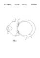
- FIG. 1shows one conventional design of a jaw frame 10 which carries two flat dies 11 with teeth for biting the pipe section's peripheral surface.
- the jaw frame 10has a cam follower or jaw roller 12 which travels along a cam surface of a power tong's rotary gear in a known manner for camming the dies 11 against the pipe section.
- a cam follower or jaw roller 12which travels along a cam surface of a power tong's rotary gear in a known manner for camming the dies 11 against the pipe section.
- two or more jaw framesare required to properly grip a pipe section.
- the flat die shownis popular because it is relatively inexpensive and may be replaced when worn out.
- the jaws' pipe engaging portionsspaced about a pipe section provide an even or uniform bite on the pipe section during use.
- the center of each pipe engaging portionshould be generally tangential to the pipe section during initial contact and even upon applying torque to the pipe section so that a maximum number of jaw teeth squarely engage the pipe section's peripheral outer surface.
- the die inserts 11are fixed in the jaw 10 to properly bite a 5.5 inch outer diameter ("OD") pipe, indicated by reference numeral 14.
- ODouter diameter
- a disadvantage of the prior art jaw designis that such desired contact is lost for different sized pipe sections, such as the 4.75 inch OD pipe section indicated by 15.
- a related problem with prior art jaw frame designsis that they do not adequately address uneven wear of the tool joints of the drill string. Even if a jaw assembly provides an even bite upon initial contact with one pipe section, it will not necessarily bite properly on another pipe section of a drill string because the OD on each pipe section is not necessarily uniform due to wear, thus reducing die-to-pipe contact. Upon the application of torque the die teeth which remain in contact with the pipe section tend to dig deeper into the pipe wall to transmit a required amount of torque for make up or break out, thereby further accelerating wear on the pipe sections.
- the jaw assemblyshould have individual die holders each of which is independently capable of squarely aligning a pipe engaging face or die insert with any one of a variety of pipe section sizes, and in particular the pipe gripping face should align itself substantially tangentially with the peripheral surface of a given pipe section upon engaging it.
- the die holder of the jaw assembly of the present inventionshould also provide an independent or secondary camming action to enhance its grip on the pipe section during make up and break out operations, and provide an even or substantially uniform bite about the pipe section.
- the die holdershould be capable of holding and using conventional and relatively inexpensive flat die inserts.
- the inventionprovides a jaw assembly for a tong to make up and break out a pipe section
- a jaw elementfor transferring torque from said tong to said pipe section; means for moving said jaw element into and out of gripping engagement with said pipe section; and, at least one die holder rotatably mounted to said jaw element and adapted to twist about a first axis oriented generally parallel to a longitudinal axis of said pipe section when engaged with said jaw element, said rotation of said at least one die holder about said first axis allowing the at least one die holder to align itself with the pipe section upon engagement therewith and providing an independent camming action against said pipe section to at least radially maintain the grip of said at least one die holder on said pipe section during said transfer of torque.
- the inventionprovides a jaw element of a hydraulically operated tong for imparting a first gripping action on a pipe section and transferring a torque thereto during make-up and break out operations
- the improvementcomprises a plurality of die holders carried by said jaw element, each die holder having a single, generally planar pipe engaging surface and each die holder being rotatably mounted to said jaw element for twisting about a first axis to align said pipe engaging surface generally tangentially with said pipe section upon engagement therewith and to provide a second camming action against said pipe section independent of said first gripping action for maintaining hold of said pipe section and avoiding slippage therebetween during said operations.
- the inventionprovides a hydraulically operated tong for use in making up and breaking out a threaded connection of axially extending pipe sections
- a tong bodyfor receiving said threaded connection therein; at least one jaw carried by said tong body; said tong body having a first gripping arrangement for radially moving said at least one jaw into gripping engagement with said threaded connection to transfer a torque thereto during said making up and breaking out; and, a plurality of die holders carried by said at least one jaw, each die holder having a single, generally planar pipe engaging surface and each die holder being rotatably mounted to said at least one jaw for twisting about a first axis to align said pipe engaging surface generally tangentially with said treaded connection upon engagement therewith and to provide a second radial gripping action against said threaded connection independent of said first gripping arrangement for maintaining grip on said threaded connection during said making up and breaking out.
- FIG. 1is a plan view of a prior art jaw frame which holds conventional flat die inserts for use in a power tong to make up and break out pipe sections;
- FIG. 2is a plan view of a jaw assembly according to a first embodiment of the present invention
- FIG. 3is a sectional view along line 3--3 of FIG. 2 showing a die, die holder and jaw frame;
- FIG. 4is a sectional view through the jaw frame along line 4--4 of FIG. 3;
- FIG. 5is a plan view of a rotary gear of a power tong carrying on the left and right sides thereof jaw assemblies according to second and third embodiments of the present invention, respectively;
- FIG. 6is an isolated plan view of a master jaw of the second embodiment of the jaw assembly
- FIG. 7ais an isolated plan view of a jaw insert of the second embodiment of the jaw assembly
- FIG. 7bis an elevated frontal view of the jaw insert of FIG. 7a;
- FIG. 7cis a sectional view along line 7c--7c of FIG. 7a;
- FIG. 8ais an elevated frontal view of a die holder of the second embodiment of the jaw assembly
- FIG. 8bis a plan view of the die holder of FIG. 8a;
- FIG. 8cis a sectional view along line 8c--8c of FIG. 8a;
- FIG. 9ais a more detailed plan view of the second embodiment of the jaw assembly engaging a pipe section
- FIG. 9bis a sectional view along line 9b--9b of FIG. 9a.
- FIG. 9cis a sectional view along line 9c--9c of FIG. 9a.
- the die holder jaw assembly of the present inventionin its various embodiments, may be used in power tongs and in back-up tongs, and in both active and passive jaw assemblies.
- a jaw assembly typically employed in a power tongis chosen herein for illustrative purposes. Referring to FIG. 5, such a jaw assembly typically travels along a cam surface 22 of a power tong's rotary gear 20 in a known manner to exert incrementally a primary or first camming action against a pipe section 24 located therein to grip the pipe section and transfer torque from the tong to the pipe section.
- the "primary camming" action in a back-up tongis provided by the hydraulic cylinder system which engages the jaw assemblies with the pipe section.
- a one-piece jaw frame or master jaw 30has a jaw roller or cam follower 32 for traveling along the rotary gear's cam surface 22 during make up and break out operations.
- a jaw roller or cam follower 32for traveling along the rotary gear's cam surface 22 during make up and break out operations.
- Opposite the roller along a front portion 33 of the jaw frameare two circumferentially spaced die holders 40 housed within correspondingly shaped recesses 34 in the jaw frame.
- the jaw's front portionis arced to generally follow the curvature of the pipe sections to be gripped, as is known in the art.
- Each elongate die holder 40has a cylindrically shaped rear portion 42 for twisting or rotating within the recess about a longitudinal axis C located immediately behind a die insert 50.
- the arc formed by the recess 34 and the die holder's rear portion 42is greater than 180 degrees to radially hold the die holder 40 within the recess without further retaining means.
- the die holder's generally planar front facehas an elongate channel 44 for accepting and holding a conventional generally planar or flat die or die insert 50.
- the die insert's outer pipe engaging surface 52typically has numerous teeth for gripping the pipe section.
- the opposed edges 46 of the channel 44are cambered or toed inwardly to prevent the die insert from popping out of the channel 44 during use.
- the die holder 40can slide in the direction of axis C for removal from the jaw frame, and the die insert 50 may likewise be removed from the die holder.
- a base plate 36extends from the bottom end of the jaw frame 30 to support the die holder 40 within the jaw frame and the die insert within the die holder's channel 44.
- a top plate 38 bolted to the top surface of the jaw frametraps the die holder 40 within the jaw recess 34 without obstructing rotation of the die holder.
- the top plate 38may extend over the die 50, although this is not preferred if quick and convenient die replacement is desired.
- FIG. 5shows two alternate embodiments of the invention.
- the jaw framehas two parts, namely a base or master jaw portion 62 which holds a jaw insert 64.
- the master jaw 62has a roller 32 at its rear end and a tongue 63 for engaging a complementary shaped cut out 65 at a rear end of the jaw insert 64, both components 62, 64 being fastened in place by a bolt, screw or the like through apertures 66.
- the jaw insert 64has a pair of recesses 34 for holding a die holder 70 in each.
- the front face 67 of the jaw insertis generally planar, the recesses 34 are oriented or angled toward each other to facilitate gripping of a pipe section, as discussed earlier. Good results have been achieved using an angle A of about 48 degrees.
- each die holder 70(FIGS. 8a-8c) has bolt receiving holes 72 at its ends to secure washers 74 (FIGS. 9a & 9b) for retaining the die 50 within the die holder's channel 44.
- Each die holder 70further has a circumferential groove 76 about its circular spine for engaging a dowel pin 69 which extends through a jaw insert hole 68 to support the die holder in the recess 34 and prevent it from slipping out of the jaw insert while allowing the die holder to twist freely about its longitudinal axis C.
- An access hole 78is provided so that the dowel pin 69 can be punched when removing the die holder.
- FIGS. 9a-9cillustrate the second embodiment of the jaw assembly in its assembled form.
- Assemblytypically first requires a die holder 70 to be placed into each of the recesses 34 of the jaw insert 64.
- Each die holder 70is retained therein by inserting a dowel pin 69 through hole 68 until it extends into the die holder's circumferential groove 76.
- the jaw insert 64may then be bolted to the master jaw 62 via the apertures 66.
- a die 50is then inserted into the die holder's channel 44 and secured therein by the washer arrangement 74.
- the third embodiment shown on the right side of FIG. 5is also a two piece jaw frame, but differs in that an integral or one-piece die insert and die holder 80 are shown. Such variation may be preferred to reduce machining, although more material is wasted when replacing the die 80.
- each flat die insertis paired with an individual die holder which is rotatable relative to the pipe segment being made up or broken out, and so the die insert's toothed face tends to squarely engage the pipe section upon initial contact, and then remain substantially tangential to the pipe section during operation.
- Such alignment or self-centeringoccurs regardless of the size of conventional pipe section used within the operational range of a particular jaw, be it 4.5 inch OD to 5.5 inch OD for one size of jaw, for instance.
- a tong employing the rotatable die holder of the present inventionmay be used on various pipe sizes without changing the die insert, die holder and jaw. It will be appreciated that for pipe sizes outside such operational range, a new jaw would be required.
- Another important feature of the die holder of the present inventionis the ability of the die insert and die holder to provide a secondary camming action independent of the primary camming action on the pipe section upon application of torque thereto.
- pipe sectionstend to slip relative to conventional fixed dies and cause damage to the peripheral surface of the pipe section, which is particularly problematic with drilling pipe where high torques are encountered.
- any twist or rotation of the pipe section in either direction relative to the die holdercauses a proportionate rotation of the die holder about its longitudinal axis C, which causes the point of contact between the die and pipe section to move radially away from the longitudinal axis C, thereby further camming the die holder against the pipe section to retain or increase the grip on the pipe section and reduce or prevent slippage.
- the same amount of dieremains in contact with the surface of the pipe section.
- the diesprovide an even bite about the pipe section, and a generally uniform radial force is transmitted through each jaw to the pipe section throughout the primary and secondary camming actions.
- the rotatable die holder of the present inventionmay be used for any type of pipe section, it is particularly suited for relatively thick walled drill pipe tool joints which are exposed to substantially higher torques than casing and production tubing.
Landscapes
- Engineering & Computer Science (AREA)
- Life Sciences & Earth Sciences (AREA)
- Geology (AREA)
- Mining & Mineral Resources (AREA)
- Mechanical Engineering (AREA)
- Physics & Mathematics (AREA)
- Environmental & Geological Engineering (AREA)
- Fluid Mechanics (AREA)
- General Life Sciences & Earth Sciences (AREA)
- Geochemistry & Mineralogy (AREA)
- Gripping Jigs, Holding Jigs, And Positioning Jigs (AREA)
- Forging (AREA)
Abstract
Description
Claims (15)
Priority Applications (2)
| Application Number | Priority Date | Filing Date | Title |
|---|---|---|---|
| US09/062,611US6070500A (en) | 1998-04-20 | 1998-04-20 | Rotatable die holder |
| CA002260521ACA2260521C (en) | 1998-04-20 | 1999-01-28 | Rotatable die holder |
Applications Claiming Priority (1)
| Application Number | Priority Date | Filing Date | Title |
|---|---|---|---|
| US09/062,611US6070500A (en) | 1998-04-20 | 1998-04-20 | Rotatable die holder |
Publications (1)
| Publication Number | Publication Date |
|---|---|
| US6070500Atrue US6070500A (en) | 2000-06-06 |
Family
ID=22043633
Family Applications (1)
| Application Number | Title | Priority Date | Filing Date |
|---|---|---|---|
| US09/062,611Expired - Fee RelatedUS6070500A (en) | 1998-04-20 | 1998-04-20 | Rotatable die holder |
Country Status (2)
| Country | Link |
|---|---|
| US (1) | US6070500A (en) |
| CA (1) | CA2260521C (en) |
Cited By (81)
| Publication number | Priority date | Publication date | Assignee | Title |
|---|---|---|---|---|
| US6483504B1 (en)* | 1998-02-17 | 2002-11-19 | Sun Microsystems, Inc. | Graphics system having a super sampled-sample buffer with efficient storage of sample position information |
| US6527047B1 (en) | 1998-08-24 | 2003-03-04 | Weatherford/Lamb, Inc. | Method and apparatus for connecting tubulars using a top drive |
| US6536520B1 (en)* | 2000-04-17 | 2003-03-25 | Weatherford/Lamb, Inc. | Top drive casing system |
| US20030141111A1 (en)* | 2000-08-01 | 2003-07-31 | Giancarlo Pia | Drilling method |
| US6622796B1 (en) | 1998-12-24 | 2003-09-23 | Weatherford/Lamb, Inc. | Apparatus and method for facilitating the connection of tubulars using a top drive |
| US20040045717A1 (en)* | 2002-09-05 | 2004-03-11 | Haugen David M. | Method and apparatus for reforming tubular connections |
| US6705405B1 (en) | 1998-08-24 | 2004-03-16 | Weatherford/Lamb, Inc. | Apparatus and method for connecting tubulars using a top drive |
| US20040051259A1 (en)* | 2002-09-12 | 2004-03-18 | National Oilwell L.P. | Jaw insert for gripping a cylindrical member and method of manufacture |
| US20040051326A1 (en)* | 2002-09-12 | 2004-03-18 | National Oilwell L.P. | Cam operated jaw force intensifier for gripping a cylindrical member |
| US6725938B1 (en) | 1998-12-24 | 2004-04-27 | Weatherford/Lamb, Inc. | Apparatus and method for facilitating the connection of tubulars using a top drive |
| US6742596B2 (en) | 2001-05-17 | 2004-06-01 | Weatherford/Lamb, Inc. | Apparatus and methods for tubular makeup interlock |
| US20040129456A1 (en)* | 1994-10-14 | 2004-07-08 | Weatherford/Lamb, Inc. | Methods and apparatus for cementing drill strings in place for one pass drilling and completion of oil and gas wells |
| US20040251025A1 (en)* | 2003-01-30 | 2004-12-16 | Giroux Richard L. | Single-direction cementing plug |
| US20050000324A1 (en)* | 2003-07-01 | 2005-01-06 | Boyd James W. | Blasthole drill with automatic breakout wrench with floating gripping dies |
| US20050034566A1 (en)* | 2003-08-11 | 2005-02-17 | Bangert Daniel S. | Tong jaw and a method for constructing the tong jaw |
| US20050051343A1 (en)* | 1998-07-22 | 2005-03-10 | Weatherford/Lamb, Inc. | Apparatus for facilitating the connection of tubulars using a top drive |
| US20050241441A1 (en)* | 2004-04-29 | 2005-11-03 | National-Oilwell, L.P. | Power tong assembly |
| US6976298B1 (en) | 1998-08-24 | 2005-12-20 | Weatherford/Lamb, Inc. | Methods and apparatus for connecting tubulars using a top drive |
| US6990876B2 (en) | 2003-05-19 | 2006-01-31 | Larry Mardian | Power tongs |
| US6994176B2 (en) | 2002-07-29 | 2006-02-07 | Weatherford/Lamb, Inc. | Adjustable rotating guides for spider or elevator |
| US20060027047A1 (en)* | 2004-08-06 | 2006-02-09 | Buck David A | Rotatable die tong jaw |
| US7004264B2 (en) | 2002-03-16 | 2006-02-28 | Weatherford/Lamb, Inc. | Bore lining and drilling |
| US7013997B2 (en) | 1994-10-14 | 2006-03-21 | Weatherford/Lamb, Inc. | Methods and apparatus for cementing drill strings in place for one pass drilling and completion of oil and gas wells |
| US7036610B1 (en) | 1994-10-14 | 2006-05-02 | Weatherford / Lamb, Inc. | Apparatus and method for completing oil and gas wells |
| US7040420B2 (en) | 1994-10-14 | 2006-05-09 | Weatherford/Lamb, Inc. | Methods and apparatus for cementing drill strings in place for one pass drilling and completion of oil and gas wells |
| US7083005B2 (en) | 2002-12-13 | 2006-08-01 | Weatherford/Lamb, Inc. | Apparatus and method of drilling with casing |
| US7090023B2 (en) | 2002-10-11 | 2006-08-15 | Weatherford/Lamb, Inc. | Apparatus and methods for drilling with casing |
| US7096982B2 (en) | 2003-02-27 | 2006-08-29 | Weatherford/Lamb, Inc. | Drill shoe |
| US7100713B2 (en) | 2000-04-28 | 2006-09-05 | Weatherford/Lamb, Inc. | Expandable apparatus for drift and reaming borehole |
| US7108084B2 (en) | 1994-10-14 | 2006-09-19 | Weatherford/Lamb, Inc. | Methods and apparatus for cementing drill strings in place for one pass drilling and completion of oil and gas wells |
| US7107875B2 (en) | 2000-03-14 | 2006-09-19 | Weatherford/Lamb, Inc. | Methods and apparatus for connecting tubulars while drilling |
| US7117957B2 (en) | 1998-12-22 | 2006-10-10 | Weatherford/Lamb, Inc. | Methods for drilling and lining a wellbore |
| US7131505B2 (en) | 2002-12-30 | 2006-11-07 | Weatherford/Lamb, Inc. | Drilling with concentric strings of casing |
| US7140445B2 (en) | 1997-09-02 | 2006-11-28 | Weatherford/Lamb, Inc. | Method and apparatus for drilling with casing |
| US7147068B2 (en) | 1994-10-14 | 2006-12-12 | Weatherford / Lamb, Inc. | Methods and apparatus for cementing drill strings in place for one pass drilling and completion of oil and gas wells |
| WO2006137743A1 (en)* | 2005-06-24 | 2006-12-28 | Hd Oil Technology As | Gripping device |
| US7165634B2 (en) | 1994-10-14 | 2007-01-23 | Weatherford/Lamb, Inc. | Method and apparatus for cementing drill strings in place for one pass drilling and completion of oil and gas wells |
| US7188547B1 (en) | 2005-12-23 | 2007-03-13 | Varco I/P, Inc. | Tubular connect/disconnect apparatus |
| US7188687B2 (en) | 1998-12-22 | 2007-03-13 | Weatherford/Lamb, Inc. | Downhole filter |
| US7191840B2 (en) | 2003-03-05 | 2007-03-20 | Weatherford/Lamb, Inc. | Casing running and drilling system |
| US7216727B2 (en) | 1999-12-22 | 2007-05-15 | Weatherford/Lamb, Inc. | Drilling bit for drilling while running casing |
| US7228901B2 (en) | 1994-10-14 | 2007-06-12 | Weatherford/Lamb, Inc. | Method and apparatus for cementing drill strings in place for one pass drilling and completion of oil and gas wells |
| US20070131416A1 (en)* | 2003-03-05 | 2007-06-14 | Odell Albert C Ii | Apparatus for gripping a tubular on a drilling rig |
| US7264067B2 (en) | 2003-10-03 | 2007-09-04 | Weatherford/Lamb, Inc. | Method of drilling and completing multiple wellbores inside a single caisson |
| US7284617B2 (en) | 2004-05-20 | 2007-10-23 | Weatherford/Lamb, Inc. | Casing running head |
| US7303022B2 (en) | 2002-10-11 | 2007-12-04 | Weatherford/Lamb, Inc. | Wired casing |
| US7311148B2 (en) | 1999-02-25 | 2007-12-25 | Weatherford/Lamb, Inc. | Methods and apparatus for wellbore construction and completion |
| US7325610B2 (en) | 2000-04-17 | 2008-02-05 | Weatherford/Lamb, Inc. | Methods and apparatus for handling and drilling with tubulars or casing |
| US7334650B2 (en) | 2000-04-13 | 2008-02-26 | Weatherford/Lamb, Inc. | Apparatus and methods for drilling a wellbore using casing |
| US20080060481A1 (en)* | 2006-09-08 | 2008-03-13 | Canrig Drilling Technology Ltd. | Oilfield tubular spin-in and spin-out detection for making-up and breaking-out tubular strings |
| US7360594B2 (en) | 2003-03-05 | 2008-04-22 | Weatherford/Lamb, Inc. | Drilling with casing latch |
| US7370707B2 (en) | 2003-04-04 | 2008-05-13 | Weatherford/Lamb, Inc. | Method and apparatus for handling wellbore tubulars |
| US7413020B2 (en) | 2003-03-05 | 2008-08-19 | Weatherford/Lamb, Inc. | Full bore lined wellbores |
| US20080196556A1 (en)* | 2002-09-12 | 2008-08-21 | National Oilwell Varco, L.P. | Cam operated jaw force intensifier for gripping a cylindrical member |
| US20080307932A1 (en)* | 2007-06-15 | 2008-12-18 | Longyear Tm, Inc. | Methods and apparatus for joint disassembly |
| US20090056931A1 (en)* | 2007-08-30 | 2009-03-05 | Longyear Tm, Inc. | Clamping and breaking device |
| US7503397B2 (en) | 2004-07-30 | 2009-03-17 | Weatherford/Lamb, Inc. | Apparatus and methods of setting and retrieving casing with drilling latch and bottom hole assembly |
| US7509722B2 (en) | 1997-09-02 | 2009-03-31 | Weatherford/Lamb, Inc. | Positioning and spinning device |
| US20090205442A1 (en)* | 2006-08-24 | 2009-08-20 | Canrig Drilling Technology Ltd. | Oilfield tubular torque wrench |
| US20090211405A1 (en)* | 2006-08-24 | 2009-08-27 | Canrig Drilling Technology Ltd. | Oilfield tubular torque wrench |
| US20090217788A1 (en)* | 2006-08-25 | 2009-09-03 | Canrig Drilling Technology Ltd. | Methods and apparatus for automated oilfield torque wrench set-up to make-up and break-out tubular strings |
| US20090277308A1 (en)* | 2008-05-12 | 2009-11-12 | Longyear Tm, Inc. | Open-faced rod spinner |
| US20090277626A1 (en)* | 2008-05-12 | 2009-11-12 | Keith William Littlely | Drill rod spinner device |
| US7650944B1 (en) | 2003-07-11 | 2010-01-26 | Weatherford/Lamb, Inc. | Vessel for well intervention |
| US7669662B2 (en) | 1998-08-24 | 2010-03-02 | Weatherford/Lamb, Inc. | Casing feeder |
| US7694744B2 (en) | 2005-01-12 | 2010-04-13 | Weatherford/Lamb, Inc. | One-position fill-up and circulating tool and method |
| US20100117282A1 (en)* | 2007-01-19 | 2010-05-13 | Vermeer Manufacturing Company | Vise for a directional drilling machine |
| US7757759B2 (en) | 2006-04-27 | 2010-07-20 | Weatherford/Lamb, Inc. | Torque sub for use with top drive |
| US20100181714A1 (en)* | 2009-01-21 | 2010-07-22 | Calhoun Larry R | Vice Jaw System for Clamping Machinable Work-pieces |
| US7845418B2 (en) | 2005-01-18 | 2010-12-07 | Weatherford/Lamb, Inc. | Top drive torque booster |
| US7882902B2 (en) | 2006-11-17 | 2011-02-08 | Weatherford/Lamb, Inc. | Top drive interlock |
| USRE42877E1 (en) | 2003-02-07 | 2011-11-01 | Weatherford/Lamb, Inc. | Methods and apparatus for wellbore construction and completion |
| US8585110B2 (en) | 2011-12-31 | 2013-11-19 | National Oilwell Varco, L.P. | Internal pipe gripping tool |
| US8752619B2 (en) | 2010-04-21 | 2014-06-17 | National Oilwell Varco, L.P. | Apparatus for suspending a downhole well string |
| US9593543B2 (en) | 2013-12-30 | 2017-03-14 | Bly Ip Inc. | Drill rod handling system for moving drill rods to and from an operative position |
| US10066451B2 (en) | 2015-12-22 | 2018-09-04 | Bly Ip Inc. | Drill rod clamping system and methods of using same |
| US20200332608A1 (en)* | 2019-04-17 | 2020-10-22 | Black Diamond Oilfield Rentals LLC | Elevator grip lifting and rotary slip holding system and methods thereof |
| US11060360B2 (en) | 2015-04-07 | 2021-07-13 | Canrig Robotic Technologies As | Apparatus and method for gripping a tubular member |
| US11572746B2 (en)* | 2019-10-18 | 2023-02-07 | Weatherford Technology Holdings Llc | Rotary gripping apparatus for a power tong |
| US20240279990A1 (en)* | 2023-02-22 | 2024-08-22 | M & M Oil Tools, LLC | Die adaptor and method |
| USD1081301S1 (en)* | 2025-01-10 | 2025-07-01 | Phillip Bellamy | Chevron tool jaw |
Citations (10)
| Publication number | Priority date | Publication date | Assignee | Title |
|---|---|---|---|---|
| US1750817A (en)* | 1928-03-31 | 1930-03-18 | William E Root | Tongs |
| US2150611A (en)* | 1938-01-20 | 1939-03-14 | Carrie Speck | Pipe tongs |
| US4060014A (en)* | 1976-04-29 | 1977-11-29 | Joy Manufacturing Company | Power tong |
| US4437363A (en)* | 1981-06-29 | 1984-03-20 | Joy Manufacturing Company | Dual camming action jaw assembly and power tong |
| US5022291A (en)* | 1990-08-06 | 1991-06-11 | Mcbain Corey L | Pliers having a pivotal jaw |
| US5159860A (en)* | 1991-04-12 | 1992-11-03 | Weatherford/Lamb, Inc. | Rotary for a power tong |
| US5161439A (en)* | 1991-10-21 | 1992-11-10 | Wesch Jr William E | Pivoting jaw assembly |
| US5167173A (en)* | 1991-04-12 | 1992-12-01 | Weatherford/Lamb, Inc. | Tong |
| US5172613A (en)* | 1989-12-07 | 1992-12-22 | Wesch Jr William E | Power tongs with improved gripping means |
| US5778742A (en)* | 1995-11-07 | 1998-07-14 | Eckel Manufacturing Company, Inc. | Hydraulic backup tong |
- 1998
- 1998-04-20USUS09/062,611patent/US6070500A/ennot_activeExpired - Fee Related
- 1999
- 1999-01-28CACA002260521Apatent/CA2260521C/ennot_activeExpired - Fee Related
Patent Citations (10)
| Publication number | Priority date | Publication date | Assignee | Title |
|---|---|---|---|---|
| US1750817A (en)* | 1928-03-31 | 1930-03-18 | William E Root | Tongs |
| US2150611A (en)* | 1938-01-20 | 1939-03-14 | Carrie Speck | Pipe tongs |
| US4060014A (en)* | 1976-04-29 | 1977-11-29 | Joy Manufacturing Company | Power tong |
| US4437363A (en)* | 1981-06-29 | 1984-03-20 | Joy Manufacturing Company | Dual camming action jaw assembly and power tong |
| US5172613A (en)* | 1989-12-07 | 1992-12-22 | Wesch Jr William E | Power tongs with improved gripping means |
| US5022291A (en)* | 1990-08-06 | 1991-06-11 | Mcbain Corey L | Pliers having a pivotal jaw |
| US5159860A (en)* | 1991-04-12 | 1992-11-03 | Weatherford/Lamb, Inc. | Rotary for a power tong |
| US5167173A (en)* | 1991-04-12 | 1992-12-01 | Weatherford/Lamb, Inc. | Tong |
| US5161439A (en)* | 1991-10-21 | 1992-11-10 | Wesch Jr William E | Pivoting jaw assembly |
| US5778742A (en)* | 1995-11-07 | 1998-07-14 | Eckel Manufacturing Company, Inc. | Hydraulic backup tong |
Cited By (140)
| Publication number | Priority date | Publication date | Assignee | Title |
|---|---|---|---|---|
| US7100710B2 (en) | 1994-10-14 | 2006-09-05 | Weatherford/Lamb, Inc. | Methods and apparatus for cementing drill strings in place for one pass drilling and completion of oil and gas wells |
| US7013997B2 (en) | 1994-10-14 | 2006-03-21 | Weatherford/Lamb, Inc. | Methods and apparatus for cementing drill strings in place for one pass drilling and completion of oil and gas wells |
| US20040129456A1 (en)* | 1994-10-14 | 2004-07-08 | Weatherford/Lamb, Inc. | Methods and apparatus for cementing drill strings in place for one pass drilling and completion of oil and gas wells |
| US7228901B2 (en) | 1994-10-14 | 2007-06-12 | Weatherford/Lamb, Inc. | Method and apparatus for cementing drill strings in place for one pass drilling and completion of oil and gas wells |
| US7165634B2 (en) | 1994-10-14 | 2007-01-23 | Weatherford/Lamb, Inc. | Method and apparatus for cementing drill strings in place for one pass drilling and completion of oil and gas wells |
| US7040420B2 (en) | 1994-10-14 | 2006-05-09 | Weatherford/Lamb, Inc. | Methods and apparatus for cementing drill strings in place for one pass drilling and completion of oil and gas wells |
| US7036610B1 (en) | 1994-10-14 | 2006-05-02 | Weatherford / Lamb, Inc. | Apparatus and method for completing oil and gas wells |
| US7147068B2 (en) | 1994-10-14 | 2006-12-12 | Weatherford / Lamb, Inc. | Methods and apparatus for cementing drill strings in place for one pass drilling and completion of oil and gas wells |
| US7108084B2 (en) | 1994-10-14 | 2006-09-19 | Weatherford/Lamb, Inc. | Methods and apparatus for cementing drill strings in place for one pass drilling and completion of oil and gas wells |
| US7509722B2 (en) | 1997-09-02 | 2009-03-31 | Weatherford/Lamb, Inc. | Positioning and spinning device |
| US7140445B2 (en) | 1997-09-02 | 2006-11-28 | Weatherford/Lamb, Inc. | Method and apparatus for drilling with casing |
| US6483504B1 (en)* | 1998-02-17 | 2002-11-19 | Sun Microsystems, Inc. | Graphics system having a super sampled-sample buffer with efficient storage of sample position information |
| US7665531B2 (en) | 1998-07-22 | 2010-02-23 | Weatherford/Lamb, Inc. | Apparatus for facilitating the connection of tubulars using a top drive |
| US20050051343A1 (en)* | 1998-07-22 | 2005-03-10 | Weatherford/Lamb, Inc. | Apparatus for facilitating the connection of tubulars using a top drive |
| US7137454B2 (en) | 1998-07-22 | 2006-11-21 | Weatherford/Lamb, Inc. | Apparatus for facilitating the connection of tubulars using a top drive |
| US6705405B1 (en) | 1998-08-24 | 2004-03-16 | Weatherford/Lamb, Inc. | Apparatus and method for connecting tubulars using a top drive |
| US7090021B2 (en) | 1998-08-24 | 2006-08-15 | Bernd-Georg Pietras | Apparatus for connecting tublars using a top drive |
| US7451826B2 (en) | 1998-08-24 | 2008-11-18 | Weatherford/Lamb, Inc. | Apparatus for connecting tubulars using a top drive |
| US20040149451A1 (en)* | 1998-08-24 | 2004-08-05 | Weatherford/Lamb, Inc. | Method and apparatus for connecting tubulars using a top drive |
| US7353880B2 (en) | 1998-08-24 | 2008-04-08 | Weatherford/Lamb, Inc. | Method and apparatus for connecting tubulars using a top drive |
| US7021374B2 (en) | 1998-08-24 | 2006-04-04 | Weatherford/Lamb, Inc. | Method and apparatus for connecting tubulars using a top drive |
| US7513300B2 (en) | 1998-08-24 | 2009-04-07 | Weatherford/Lamb, Inc. | Casing running and drilling system |
| US6527047B1 (en) | 1998-08-24 | 2003-03-04 | Weatherford/Lamb, Inc. | Method and apparatus for connecting tubulars using a top drive |
| US6976298B1 (en) | 1998-08-24 | 2005-12-20 | Weatherford/Lamb, Inc. | Methods and apparatus for connecting tubulars using a top drive |
| US7617866B2 (en) | 1998-08-24 | 2009-11-17 | Weatherford/Lamb, Inc. | Methods and apparatus for connecting tubulars using a top drive |
| US7669662B2 (en) | 1998-08-24 | 2010-03-02 | Weatherford/Lamb, Inc. | Casing feeder |
| US6688398B2 (en) | 1998-08-24 | 2004-02-10 | Weatherford/Lamb, Inc. | Method and apparatus for connecting tubulars using a top drive |
| US7219744B2 (en) | 1998-08-24 | 2007-05-22 | Weatherford/Lamb, Inc. | Method and apparatus for connecting tubulars using a top drive |
| US7117957B2 (en) | 1998-12-22 | 2006-10-10 | Weatherford/Lamb, Inc. | Methods for drilling and lining a wellbore |
| US7188687B2 (en) | 1998-12-22 | 2007-03-13 | Weatherford/Lamb, Inc. | Downhole filter |
| US7128161B2 (en) | 1998-12-24 | 2006-10-31 | Weatherford/Lamb, Inc. | Apparatus and methods for facilitating the connection of tubulars using a top drive |
| US7004259B2 (en) | 1998-12-24 | 2006-02-28 | Weatherford/Lamb, Inc. | Apparatus and method for facilitating the connection of tubulars using a top drive |
| US6622796B1 (en) | 1998-12-24 | 2003-09-23 | Weatherford/Lamb, Inc. | Apparatus and method for facilitating the connection of tubulars using a top drive |
| US6725938B1 (en) | 1998-12-24 | 2004-04-27 | Weatherford/Lamb, Inc. | Apparatus and method for facilitating the connection of tubulars using a top drive |
| US7213656B2 (en) | 1998-12-24 | 2007-05-08 | Weatherford/Lamb, Inc. | Apparatus and method for facilitating the connection of tubulars using a top drive |
| US7311148B2 (en) | 1999-02-25 | 2007-12-25 | Weatherford/Lamb, Inc. | Methods and apparatus for wellbore construction and completion |
| US7216727B2 (en) | 1999-12-22 | 2007-05-15 | Weatherford/Lamb, Inc. | Drilling bit for drilling while running casing |
| US7107875B2 (en) | 2000-03-14 | 2006-09-19 | Weatherford/Lamb, Inc. | Methods and apparatus for connecting tubulars while drilling |
| US7334650B2 (en) | 2000-04-13 | 2008-02-26 | Weatherford/Lamb, Inc. | Apparatus and methods for drilling a wellbore using casing |
| US7325610B2 (en) | 2000-04-17 | 2008-02-05 | Weatherford/Lamb, Inc. | Methods and apparatus for handling and drilling with tubulars or casing |
| US7793719B2 (en) | 2000-04-17 | 2010-09-14 | Weatherford/Lamb, Inc. | Top drive casing system |
| US7712523B2 (en) | 2000-04-17 | 2010-05-11 | Weatherford/Lamb, Inc. | Top drive casing system |
| US6536520B1 (en)* | 2000-04-17 | 2003-03-25 | Weatherford/Lamb, Inc. | Top drive casing system |
| US7918273B2 (en) | 2000-04-17 | 2011-04-05 | Weatherford/Lamb, Inc. | Top drive casing system |
| US7654325B2 (en) | 2000-04-17 | 2010-02-02 | Weatherford/Lamb, Inc. | Methods and apparatus for handling and drilling with tubulars or casing |
| US7100713B2 (en) | 2000-04-28 | 2006-09-05 | Weatherford/Lamb, Inc. | Expandable apparatus for drift and reaming borehole |
| US7093675B2 (en) | 2000-08-01 | 2006-08-22 | Weatherford/Lamb, Inc. | Drilling method |
| US20030141111A1 (en)* | 2000-08-01 | 2003-07-31 | Giancarlo Pia | Drilling method |
| US8517090B2 (en) | 2001-05-17 | 2013-08-27 | Weatherford/Lamb, Inc. | Apparatus and methods for tubular makeup interlock |
| US6938697B2 (en) | 2001-05-17 | 2005-09-06 | Weatherford/Lamb, Inc. | Apparatus and methods for tubular makeup interlock |
| US20040173358A1 (en)* | 2001-05-17 | 2004-09-09 | Weatherford/Lamb, Inc. | Apparatus and methods for tubular makeup interlock |
| US6742596B2 (en) | 2001-05-17 | 2004-06-01 | Weatherford/Lamb, Inc. | Apparatus and methods for tubular makeup interlock |
| US7073598B2 (en) | 2001-05-17 | 2006-07-11 | Weatherford/Lamb, Inc. | Apparatus and methods for tubular makeup interlock |
| US7896084B2 (en) | 2001-05-17 | 2011-03-01 | Weatherford/Lamb, Inc. | Apparatus and methods for tubular makeup interlock |
| US7281587B2 (en) | 2001-05-17 | 2007-10-16 | Weatherford/Lamb, Inc. | Apparatus and methods for tubular makeup interlock |
| US7004264B2 (en) | 2002-03-16 | 2006-02-28 | Weatherford/Lamb, Inc. | Bore lining and drilling |
| US7448456B2 (en) | 2002-07-29 | 2008-11-11 | Weatherford/Lamb, Inc. | Adjustable rotating guides for spider or elevator |
| US6994176B2 (en) | 2002-07-29 | 2006-02-07 | Weatherford/Lamb, Inc. | Adjustable rotating guides for spider or elevator |
| US20040045717A1 (en)* | 2002-09-05 | 2004-03-11 | Haugen David M. | Method and apparatus for reforming tubular connections |
| US7100697B2 (en) | 2002-09-05 | 2006-09-05 | Weatherford/Lamb, Inc. | Method and apparatus for reforming tubular connections |
| US7748297B2 (en) | 2002-09-12 | 2010-07-06 | National Oilwell Varco, L.P. | Cam operated jaw force intensifier for gripping a cylindrical member |
| US6971283B2 (en)* | 2002-09-12 | 2005-12-06 | National-Oilwell, L.P. | Jaw insert for gripping a cylindrical member and method of manufacture |
| US20040051259A1 (en)* | 2002-09-12 | 2004-03-18 | National Oilwell L.P. | Jaw insert for gripping a cylindrical member and method of manufacture |
| US20040051326A1 (en)* | 2002-09-12 | 2004-03-18 | National Oilwell L.P. | Cam operated jaw force intensifier for gripping a cylindrical member |
| US20080196556A1 (en)* | 2002-09-12 | 2008-08-21 | National Oilwell Varco, L.P. | Cam operated jaw force intensifier for gripping a cylindrical member |
| US7303022B2 (en) | 2002-10-11 | 2007-12-04 | Weatherford/Lamb, Inc. | Wired casing |
| US7090023B2 (en) | 2002-10-11 | 2006-08-15 | Weatherford/Lamb, Inc. | Apparatus and methods for drilling with casing |
| US7083005B2 (en) | 2002-12-13 | 2006-08-01 | Weatherford/Lamb, Inc. | Apparatus and method of drilling with casing |
| US7131505B2 (en) | 2002-12-30 | 2006-11-07 | Weatherford/Lamb, Inc. | Drilling with concentric strings of casing |
| US20040251025A1 (en)* | 2003-01-30 | 2004-12-16 | Giroux Richard L. | Single-direction cementing plug |
| US7128154B2 (en) | 2003-01-30 | 2006-10-31 | Weatherford/Lamb, Inc. | Single-direction cementing plug |
| USRE42877E1 (en) | 2003-02-07 | 2011-11-01 | Weatherford/Lamb, Inc. | Methods and apparatus for wellbore construction and completion |
| US7096982B2 (en) | 2003-02-27 | 2006-08-29 | Weatherford/Lamb, Inc. | Drill shoe |
| US7360594B2 (en) | 2003-03-05 | 2008-04-22 | Weatherford/Lamb, Inc. | Drilling with casing latch |
| US20070131416A1 (en)* | 2003-03-05 | 2007-06-14 | Odell Albert C Ii | Apparatus for gripping a tubular on a drilling rig |
| US7413020B2 (en) | 2003-03-05 | 2008-08-19 | Weatherford/Lamb, Inc. | Full bore lined wellbores |
| US10138690B2 (en) | 2003-03-05 | 2018-11-27 | Weatherford Technology Holdings, Llc | Apparatus for gripping a tubular on a drilling rig |
| US7191840B2 (en) | 2003-03-05 | 2007-03-20 | Weatherford/Lamb, Inc. | Casing running and drilling system |
| US7874352B2 (en) | 2003-03-05 | 2011-01-25 | Weatherford/Lamb, Inc. | Apparatus for gripping a tubular on a drilling rig |
| US8567512B2 (en) | 2003-03-05 | 2013-10-29 | Weatherford/Lamb, Inc. | Apparatus for gripping a tubular on a drilling rig |
| US7370707B2 (en) | 2003-04-04 | 2008-05-13 | Weatherford/Lamb, Inc. | Method and apparatus for handling wellbore tubulars |
| US6990876B2 (en) | 2003-05-19 | 2006-01-31 | Larry Mardian | Power tongs |
| US6938519B2 (en)* | 2003-07-01 | 2005-09-06 | Harnischfeger Technologies, Inc. | Automatic breakout wrench with floating gripping dies |
| US20050000324A1 (en)* | 2003-07-01 | 2005-01-06 | Boyd James W. | Blasthole drill with automatic breakout wrench with floating gripping dies |
| AU2004202455B2 (en)* | 2003-07-01 | 2009-04-23 | Joy Global Surface Mining Inc | Automatic Break Out Wrench with Floating Gripping Dies |
| US7650944B1 (en) | 2003-07-11 | 2010-01-26 | Weatherford/Lamb, Inc. | Vessel for well intervention |
| US20050034566A1 (en)* | 2003-08-11 | 2005-02-17 | Bangert Daniel S. | Tong jaw and a method for constructing the tong jaw |
| US7017450B2 (en)* | 2003-08-11 | 2006-03-28 | Bangert Daniel S | Tong jaw and a method for constructing the tong jaw |
| US7264067B2 (en) | 2003-10-03 | 2007-09-04 | Weatherford/Lamb, Inc. | Method of drilling and completing multiple wellbores inside a single caisson |
| US7121166B2 (en) | 2004-04-29 | 2006-10-17 | National-Oilwell, L.P. | Power tong assembly |
| EP1591618A3 (en)* | 2004-04-29 | 2005-12-28 | National-Oilwell, L.P. | Tong assembly and method for manipulating a tubular connection |
| US20050241441A1 (en)* | 2004-04-29 | 2005-11-03 | National-Oilwell, L.P. | Power tong assembly |
| US7284617B2 (en) | 2004-05-20 | 2007-10-23 | Weatherford/Lamb, Inc. | Casing running head |
| US7503397B2 (en) | 2004-07-30 | 2009-03-17 | Weatherford/Lamb, Inc. | Apparatus and methods of setting and retrieving casing with drilling latch and bottom hole assembly |
| US7204173B2 (en)* | 2004-08-06 | 2007-04-17 | Buck David A | Rotatable die tong jaw |
| US20060027047A1 (en)* | 2004-08-06 | 2006-02-09 | Buck David A | Rotatable die tong jaw |
| US7694744B2 (en) | 2005-01-12 | 2010-04-13 | Weatherford/Lamb, Inc. | One-position fill-up and circulating tool and method |
| US7845418B2 (en) | 2005-01-18 | 2010-12-07 | Weatherford/Lamb, Inc. | Top drive torque booster |
| WO2006137743A1 (en)* | 2005-06-24 | 2006-12-28 | Hd Oil Technology As | Gripping device |
| US7188547B1 (en) | 2005-12-23 | 2007-03-13 | Varco I/P, Inc. | Tubular connect/disconnect apparatus |
| US20070193417A1 (en)* | 2005-12-23 | 2007-08-23 | West Neil E | Tubular-drill bit connect/disconnect apparatus |
| US7313986B2 (en) | 2005-12-23 | 2008-01-01 | Varco I/P, Inc. | Tubular-drill bit connect/disconnect apparatus |
| US7757759B2 (en) | 2006-04-27 | 2010-07-20 | Weatherford/Lamb, Inc. | Torque sub for use with top drive |
| US20090211405A1 (en)* | 2006-08-24 | 2009-08-27 | Canrig Drilling Technology Ltd. | Oilfield tubular torque wrench |
| US7958787B2 (en) | 2006-08-24 | 2011-06-14 | Canrig Drilling Technology Ltd. | Oilfield tubular torque wrench |
| US8042432B2 (en) | 2006-08-24 | 2011-10-25 | Canrig Drilling Technology Ltd. | Oilfield tubular torque wrench |
| US20090205442A1 (en)* | 2006-08-24 | 2009-08-20 | Canrig Drilling Technology Ltd. | Oilfield tubular torque wrench |
| US20090217788A1 (en)* | 2006-08-25 | 2009-09-03 | Canrig Drilling Technology Ltd. | Methods and apparatus for automated oilfield torque wrench set-up to make-up and break-out tubular strings |
| US9097070B2 (en) | 2006-08-25 | 2015-08-04 | Canrig Drilling Technology Ltd. | Apparatus for automated oilfield torque wrench set-up to make-up and break-out tubular strings |
| US8490520B2 (en) | 2006-09-08 | 2013-07-23 | Canrig Drilling Technology Ltd. | Oilfield tubular spin-in and spin-out detection for making-up and breaking-out tubular strings |
| US10329857B2 (en) | 2006-09-08 | 2019-06-25 | Nabors Drilling Technologies Usa, Inc. | Oilfield tubular spin-in and spin-out detection for making-up and breaking-out tubular strings |
| US20080060481A1 (en)* | 2006-09-08 | 2008-03-13 | Canrig Drilling Technology Ltd. | Oilfield tubular spin-in and spin-out detection for making-up and breaking-out tubular strings |
| US9404324B2 (en) | 2006-09-08 | 2016-08-02 | Canrig Drilling Technology Ltd. | Oilfield tubular spin-in and spin-out detection for making-up and breaking-out tubular strings |
| US8074537B2 (en) | 2006-09-08 | 2011-12-13 | Canrig Drilling Technology Ltd. | Oilfield tubular spin-in and spin-out detection for making-up and breaking-out tubular strings |
| US7882902B2 (en) | 2006-11-17 | 2011-02-08 | Weatherford/Lamb, Inc. | Top drive interlock |
| US20100117282A1 (en)* | 2007-01-19 | 2010-05-13 | Vermeer Manufacturing Company | Vise for a directional drilling machine |
| US7997166B2 (en) | 2007-06-15 | 2011-08-16 | Longyear Tm, Inc. | Methods and apparatus for joint disassembly |
| US20080307932A1 (en)* | 2007-06-15 | 2008-12-18 | Longyear Tm, Inc. | Methods and apparatus for joint disassembly |
| US20090056931A1 (en)* | 2007-08-30 | 2009-03-05 | Longyear Tm, Inc. | Clamping and breaking device |
| US7997167B2 (en)* | 2007-08-30 | 2011-08-16 | Longyear Tm, Inc. | Clamping and breaking device |
| EP2183460A4 (en)* | 2007-08-30 | 2016-01-20 | Longyear Tm Inc | Clamping and breaking device |
| WO2009032705A1 (en) | 2007-08-30 | 2009-03-12 | Longyear Tm, Inc. | Clamping and breaking device |
| US20090277626A1 (en)* | 2008-05-12 | 2009-11-12 | Keith William Littlely | Drill rod spinner device |
| US8006590B2 (en) | 2008-05-12 | 2011-08-30 | Longyear Tm, Inc. | Open-faced rod spinner |
| US7849929B2 (en) | 2008-05-12 | 2010-12-14 | Longyear Tm, Inc. | Drill rod spinner device |
| US20090277308A1 (en)* | 2008-05-12 | 2009-11-12 | Longyear Tm, Inc. | Open-faced rod spinner |
| US8291791B2 (en) | 2008-05-12 | 2012-10-23 | Longyear Tm, Inc. | Open-faced rod spinning device |
| US20100181714A1 (en)* | 2009-01-21 | 2010-07-22 | Calhoun Larry R | Vice Jaw System for Clamping Machinable Work-pieces |
| US8752619B2 (en) | 2010-04-21 | 2014-06-17 | National Oilwell Varco, L.P. | Apparatus for suspending a downhole well string |
| US8585110B2 (en) | 2011-12-31 | 2013-11-19 | National Oilwell Varco, L.P. | Internal pipe gripping tool |
| US9593543B2 (en) | 2013-12-30 | 2017-03-14 | Bly Ip Inc. | Drill rod handling system for moving drill rods to and from an operative position |
| US10047576B2 (en) | 2013-12-30 | 2018-08-14 | Bly Ip Inc. | Drill rod handling system for moving drill rods to and from an operative position |
| US11060360B2 (en) | 2015-04-07 | 2021-07-13 | Canrig Robotic Technologies As | Apparatus and method for gripping a tubular member |
| US10066451B2 (en) | 2015-12-22 | 2018-09-04 | Bly Ip Inc. | Drill rod clamping system and methods of using same |
| US20200332608A1 (en)* | 2019-04-17 | 2020-10-22 | Black Diamond Oilfield Rentals LLC | Elevator grip lifting and rotary slip holding system and methods thereof |
| US11624247B2 (en)* | 2019-04-17 | 2023-04-11 | Black Diamond Oilfield Rentals LLC | Elevator grip lifting and rotary slip holding system and methods thereof |
| US11572746B2 (en)* | 2019-10-18 | 2023-02-07 | Weatherford Technology Holdings Llc | Rotary gripping apparatus for a power tong |
| US20240279990A1 (en)* | 2023-02-22 | 2024-08-22 | M & M Oil Tools, LLC | Die adaptor and method |
| US12320212B2 (en)* | 2023-02-22 | 2025-06-03 | M&M Oil Tools, LLC | Die adaptor and method |
| USD1081301S1 (en)* | 2025-01-10 | 2025-07-01 | Phillip Bellamy | Chevron tool jaw |
Also Published As
| Publication number | Publication date |
|---|---|
| CA2260521C (en) | 2007-09-25 |
| CA2260521A1 (en) | 1999-10-20 |
Similar Documents
| Publication | Publication Date | Title |
|---|---|---|
| US6070500A (en) | Rotatable die holder | |
| US5150642A (en) | Device for applying torque to a tubular member | |
| US4649777A (en) | Back-up power tongs | |
| US4084453A (en) | Power tongs | |
| EP1161613B1 (en) | Tong | |
| US4869137A (en) | Jaws for power tongs and bucking units | |
| US4576067A (en) | Jaw assembly | |
| EP0862509B1 (en) | Improved back-up power tongs | |
| US20020108748A1 (en) | Replaceable tong die inserts for pipe tongs | |
| US10364620B2 (en) | Drill rod clamping system and methods of using same | |
| EP0374533A1 (en) | Active jaw for a power tong | |
| US5865073A (en) | Torque machines | |
| EP0630440A1 (en) | Slip-type gripping assembly | |
| US20090272233A1 (en) | Tong Unit Having Multi-Jaw Assembly Gripping System | |
| US7748297B2 (en) | Cam operated jaw force intensifier for gripping a cylindrical member | |
| BRPI0702924A2 (en) | arbor and machine tool turret | |
| NO323655B1 (en) | Power pliers with closed head | |
| US4688453A (en) | Apparatus for making and braking connections between screw threaded tubular members | |
| US7204173B2 (en) | Rotatable die tong jaw | |
| US4089240A (en) | Power tongs | |
| US4060014A (en) | Power tong | |
| US7197963B1 (en) | Apparatus for clamping a drilling tubular against rotation | |
| US3434191A (en) | Apparatus for protecting well pipe | |
| US6276238B1 (en) | Open top rotating vise | |
| JPH0762968A (en) | Fitting/removing device for tube body |
Legal Events
| Date | Code | Title | Description |
|---|---|---|---|
| AS | Assignment | Owner name:WHITE BEAR ENERGY SERVICES LTD., CANADA Free format text:ASSIGNMENT OF ASSIGNORS INTEREST;ASSIGNORS:DLASK, JIRI;RIGBY, DARRALL;REEL/FRAME:009115/0171 Effective date:19980415 | |
| AS | Assignment | Owner name:W. E. RENTALS 2K LTD., CANADA Free format text:ASSIGNMENT OF ASSIGNORS INTEREST;ASSIGNOR:WHITE BEAR ENERGY SERVICES LTD.;REEL/FRAME:014108/0109 Effective date:20030801 | |
| AS | Assignment | Owner name:ENGLISH, BOYD, ALBERTA Free format text:ASSIGNMENT OF ASSIGNORS INTEREST;ASSIGNOR:W.E. RENTALS 2K LTD.;REEL/FRAME:014108/0411 Effective date:20030802 Owner name:WALKOM, KEITH, ALBERTA Free format text:ASSIGNMENT OF ASSIGNORS INTEREST;ASSIGNOR:W.E. RENTALS 2K LTD.;REEL/FRAME:014108/0411 Effective date:20030802 | |
| FPAY | Fee payment | Year of fee payment:4 | |
| SULP | Surcharge for late payment | ||
| FPAY | Fee payment | Year of fee payment:8 | |
| REMI | Maintenance fee reminder mailed | ||
| LAPS | Lapse for failure to pay maintenance fees | ||
| STCH | Information on status: patent discontinuation | Free format text:PATENT EXPIRED DUE TO NONPAYMENT OF MAINTENANCE FEES UNDER 37 CFR 1.362 | |
| FP | Lapsed due to failure to pay maintenance fee | Effective date:20120606 |