US6070440A - High pressure cleaning vessel with a space saving door opening/closing apparatus - Google Patents
High pressure cleaning vessel with a space saving door opening/closing apparatusDownload PDFInfo
- Publication number
- US6070440A US6070440AUS08/998,394US99839497AUS6070440AUS 6070440 AUS6070440 AUS 6070440AUS 99839497 AUS99839497 AUS 99839497AUS 6070440 AUS6070440 AUS 6070440A
- Authority
- US
- United States
- Prior art keywords
- cleaning vessel
- door
- cleaning
- vessel
- frame
- Prior art date
- Legal status (The legal status is an assumption and is not a legal conclusion. Google has not performed a legal analysis and makes no representation as to the accuracy of the status listed.)
- Expired - Lifetime
Links
- 238000004140cleaningMethods0.000titleclaimsabstractdescription147
- 238000005108dry cleaningMethods0.000claimsabstractdescription35
- 239000000356contaminantSubstances0.000claimsdescription9
- 239000012530fluidSubstances0.000claimsdescription5
- 239000000758substrateSubstances0.000claimsdescription5
- CURLTUGMZLYLDI-UHFFFAOYSA-NCarbon dioxideChemical compoundO=C=OCURLTUGMZLYLDI-UHFFFAOYSA-N0.000description72
- 229910002092carbon dioxideInorganic materials0.000description36
- 239000001569carbon dioxideSubstances0.000description36
- 239000007788liquidSubstances0.000description27
- 239000002904solventSubstances0.000description16
- 238000000034methodMethods0.000description8
- 230000008569processEffects0.000description6
- 238000010926purgeMethods0.000description6
- 238000011084recoveryMethods0.000description6
- 238000003860storageMethods0.000description6
- 230000007246mechanismEffects0.000description4
- 239000002245particleSubstances0.000description4
- CYTYCFOTNPOANT-UHFFFAOYSA-NPerchloroethyleneChemical groupClC(Cl)=C(Cl)ClCYTYCFOTNPOANT-UHFFFAOYSA-N0.000description3
- 238000013019agitationMethods0.000description3
- 230000008901benefitEffects0.000description3
- 239000007791liquid phaseSubstances0.000description3
- 239000012071phaseSubstances0.000description3
- 238000001816coolingMethods0.000description2
- 239000003599detergentSubstances0.000description2
- 238000010586diagramMethods0.000description2
- 238000001035dryingMethods0.000description2
- 239000003208petroleumSubstances0.000description2
- 238000005406washingMethods0.000description2
- UOCLXMDMGBRAIB-UHFFFAOYSA-N1,1,1-trichloroethaneChemical compoundCC(Cl)(Cl)ClUOCLXMDMGBRAIB-UHFFFAOYSA-N0.000description1
- AJDIZQLSFPQPEY-UHFFFAOYSA-N1,1,2-TrichlorotrifluoroethaneChemical compoundFC(F)(Cl)C(F)(Cl)ClAJDIZQLSFPQPEY-UHFFFAOYSA-N0.000description1
- 239000012141concentrateSubstances0.000description1
- 230000000694effectsEffects0.000description1
- 230000005484gravityEffects0.000description1
- 231100001261hazardousToxicity0.000description1
- 230000036541healthEffects0.000description1
- 238000004519manufacturing processMethods0.000description1
- 238000012986modificationMethods0.000description1
- 230000004048modificationEffects0.000description1
- 239000003921oilSubstances0.000description1
- 238000005086pumpingMethods0.000description1
- 238000000926separation methodMethods0.000description1
- 239000000344soapSubstances0.000description1
- 239000002689soilSubstances0.000description1
- -1surfacantSubstances0.000description1
- 231100000606suspected carcinogenToxicity0.000description1
Images


Classifications
- F—MECHANICAL ENGINEERING; LIGHTING; HEATING; WEAPONS; BLASTING
- F16—ENGINEERING ELEMENTS AND UNITS; GENERAL MEASURES FOR PRODUCING AND MAINTAINING EFFECTIVE FUNCTIONING OF MACHINES OR INSTALLATIONS; THERMAL INSULATION IN GENERAL
- F16J—PISTONS; CYLINDERS; SEALINGS
- F16J13/00—Covers or similar closure members for pressure vessels in general
- F16J13/22—Covers or similar closure members for pressure vessels in general with movement parallel to the plane of the opening
- D—TEXTILES; PAPER
- D06—TREATMENT OF TEXTILES OR THE LIKE; LAUNDERING; FLEXIBLE MATERIALS NOT OTHERWISE PROVIDED FOR
- D06F—LAUNDERING, DRYING, IRONING, PRESSING OR FOLDING TEXTILE ARTICLES
- D06F43/00—Dry-cleaning apparatus or methods using volatile solvents
- D06F43/02—Dry-cleaning apparatus or methods using volatile solvents having one rotary cleaning receptacle only
- F—MECHANICAL ENGINEERING; LIGHTING; HEATING; WEAPONS; BLASTING
- F16—ENGINEERING ELEMENTS AND UNITS; GENERAL MEASURES FOR PRODUCING AND MAINTAINING EFFECTIVE FUNCTIONING OF MACHINES OR INSTALLATIONS; THERMAL INSULATION IN GENERAL
- F16J—PISTONS; CYLINDERS; SEALINGS
- F16J13/00—Covers or similar closure members for pressure vessels in general
- F16J13/02—Detachable closure members; Means for tightening closures
- F16J13/12—Detachable closure members; Means for tightening closures attached by wedging action by means of screw-thread, interrupted screw-thread, bayonet closure, or the like
Definitions
- This inventiongenerally relates to pressurized liquid cleaning apparatus and, more particularly, to an apparatus for opening and closing a door to a high pressure cleaning vessel which requires minimal clearance to operate.
- one of the more critical aspects of a liquid carbon dioxide dry cleaning apparatusis the area required for opening and closing of the door of the pressurized cleaning vessel to permit loading and removal of garments or other items. Since the cleaning vessel in a liquid carbon dioxide system operates at a high pressure (e.g. 500-850 psi) under ambient temperature conditions in order to ensure that the carbon dioxide remains in a liquid phase, a relatively bulky, heavy walled door must be used.
- a relatively bulky, heavy walled doorwhich could be used on such a liquid carbon dioxide cleaning vessel is a conventional hinged door. Due to the weight of the door, an opening mechanism typically would have to be provided for swinging the door to an open position at the side of the cleaning vessel.
- a more specific object of the present inventionis to provide an apparatus for opening and closing a door to a high pressure cleaning vessel of a dry cleaning machine which requires minimal clearance space for operation.
- Another object of the present inventionis to provide an apparatus as characterized above which occupies a minimal amount of space in both the open and closed positions and operates entirely within the lateral confines of the cleaning vessel.
- FIG. 1is a schematic block diagram of an illustrative dense phase liquid dry cleaning apparatus having a cleaning vessel constructed in accordance with the teachings of the present invention.
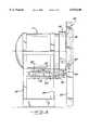
- FIG. 2is a side elevation view of the cleaning vessel of the illustrative dry cleaning apparatus showing the cleaning vessel door in a closed position.
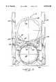
- FIG. 3is a front elevation view of the cleaning vessel showing the door in the closed position.
- FIG. 4is a partial top section view of the cleaning vessel showing the door in the closed position.
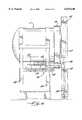
- FIG. 5is a side elevation view of the cleaning vessel showing the door in an intermediate position.
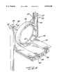
- FIG. 6is a side elevation view of the cleaning vessel showing the door in an open position.
- FIG. 9is a rear perspective view of the door opening/closing apparatus of the illustrative cleaning apparatus.
- This agitationmay be accomplished by rotation of the basket 17 and/or by the direction of liquid carbon dioxide into the interior of the basket, as disclosed in commonly assigned U.S. application Ser. No. 08/998,399, filed Dec. 24, 1997.
- soluble contaminantsdissolve in the liquid carbon dioxide.
- the cleaning vessel 11may be further equipped with a pressure check valve 20, heat exchanger 21, pressure sensor, and temperature sensor to aid in temperature and pressure control of the carbon dioxide in the cleaning vessel 11.
- the liquid carbon dioxideIn order to effectively remove the contaminants from the items, the liquid carbon dioxide must be at a temperature at which the contaminants are substantially soluble. Accordingly, when liquid carbon dioxide is used, the desired pressure in the cleaning vessel 11 ranges from about 700 psi (48 bar) to about 850 psi (59 bar) while the temperature ranges from about 55° F. (13° C.) to about 80° F. (24° C.).
- the carbon dioxidewill be in a supercritical fluidic state, and may be too aggressive for some dry-cleaning applications.
- it is desirable to maintain the temperature above 32° F. as any drop below this critical temperaturemay cause damage to the garments.
- a cyclone separator 24is provided.
- the separated particlesare gravity fed from the cyclone separator 24 into the base of the solvent recovery device 12 where they can be removed as desired.
- a pump 13In order to circulate the liquified carbon dioxide through the apparatus, a pump 13 is provided.
- the pump 13is used to transfer liquified carbon dioxide between the storage tank 15, the solvent recovery device 12, the cyclone separator 24 and/or the cleaning vessel 11.
- a lint trap 28is provided.
- the lint trap 28is equipped with a removable inner basket to allow for easy access and to additionally provide a container within which detergent, surfacant, soap or the like may be dissolved into the cleaning solution as the wash cycle progresses.
- a filter 30is also provided to remove finer particles, for example, 1 to 20 microns.
- the horizontal actuator assembly 46moves the door 40 in a generally horizontal direction perpendicular to the front wall 42 of the cleaning vessel out of engagement with the locking ring 56 and to an intermediate position wherein the door and the side arms are spaced a short distance from the front of the cleaning vessel as shown in FIG. 5.
- the horizontal actuator assembly 46includes a pneumatic actuating cylinder 58 and a pair of generally horizontal running rails 60 which are carried by the cleaning vessel 11. As best shown in FIG.
- the rails 60are arranged on a horizontal shelf 62 in the cradle 54 below the cleaning chamber and are operatively connected to the base member 50 such that the frame can slide horizontally relative cleaning vessel along the rails.
- the pneumatic cylinder 58is also arranged generally horizontally on the cleaning vessel cradle 54 and is operatively connected to the frame 44 such that extension of the cylinder 58 moves the frame, and with it the door 40, from the closed position to the intermediate position.
- arranging the pneumatic cylinder 58 and the rails 60 in the cradle support structure 54 underneath the cleaning chamberalso helps conserve space.
- the open/closing assemblyincludes a vertical actuating assembly 48.
- the vertical actuating assembly 48comprises a pair of pneumatic cylinders 64 each of which is carried in a vertical orientation by a respective one of the side arms 52 of the frame.
- the pneumatic cylinders 64when extended, they lower the door 40 in a generally vertical direction parallel to the front wall of the cleaning vessel to the fully open position (FIGS. 6 and 7), wherein the door is arranged generally below the opening in the front wall 42 of the cleaning vessel.
- the side arms 52shield the operation of the cylinders 64 in order to prevent objects or an operator's appendage from being caught.
- the side arms 52may also include vertical ways 53 (FIGS. 4, 8 and 9) which slidingly receive a portion of the sides of the door 40 and guide the door as it is lowered.
- FIG. 7once the door 40 is fully open, an operator has full access to the interior of the cleaning chamber for removing and loading garments or other items.
- the door 40is closed simply by reversing the operation, i.e. first raising the door in a generally vertical direction to the intermediate position and then moving the door in a generally horizontally direction back into engagement with the locking ring 56.
- the door opening/closing apparatus of the cleaning vessel of the illustrative dry cleaning apparatusrequires minimal clearance space to operate as compared to conventional swinging or horizontally sliding doors. As such, the dry cleaning apparatus can be installed into a significantly smaller space.
Landscapes
- Engineering & Computer Science (AREA)
- General Engineering & Computer Science (AREA)
- Mechanical Engineering (AREA)
- Textile Engineering (AREA)
- Cleaning By Liquid Or Steam (AREA)
Abstract
Description
Claims (18)
Priority Applications (1)
| Application Number | Priority Date | Filing Date | Title |
|---|---|---|---|
| US08/998,394US6070440A (en) | 1997-12-24 | 1997-12-24 | High pressure cleaning vessel with a space saving door opening/closing apparatus |
Applications Claiming Priority (1)
| Application Number | Priority Date | Filing Date | Title |
|---|---|---|---|
| US08/998,394US6070440A (en) | 1997-12-24 | 1997-12-24 | High pressure cleaning vessel with a space saving door opening/closing apparatus |
Publications (1)
| Publication Number | Publication Date |
|---|---|
| US6070440Atrue US6070440A (en) | 2000-06-06 |
Family
ID=25545154
Family Applications (1)
| Application Number | Title | Priority Date | Filing Date |
|---|---|---|---|
| US08/998,394Expired - LifetimeUS6070440A (en) | 1997-12-24 | 1997-12-24 | High pressure cleaning vessel with a space saving door opening/closing apparatus |
Country Status (1)
| Country | Link |
|---|---|
| US (1) | US6070440A (en) |
Cited By (18)
| Publication number | Priority date | Publication date | Assignee | Title |
|---|---|---|---|---|
| US6481247B1 (en)* | 1998-07-02 | 2002-11-19 | Fedegari Autoclavi Spa | Cleaning method and apparatus with dense phase fluid |
| US20030051514A1 (en)* | 1999-08-18 | 2003-03-20 | Lg Electronics Inc. | Washing machine |
| US6589592B1 (en) | 1999-09-24 | 2003-07-08 | Micell Technologies | Methods of coating articles using a densified coating system |
| US6666050B2 (en) | 1999-09-24 | 2003-12-23 | Micell Technologies, Inc. | Apparatus for conserving vapor in a carbon dioxide dry cleaning system |
| EP1012372A4 (en)* | 1997-09-09 | 2004-06-23 | Snap Tite Tech Inc | Dry cleaning system using carbon dioxide |
| US20050022850A1 (en)* | 2003-07-29 | 2005-02-03 | Supercritical Systems, Inc. | Regulation of flow of processing chemistry only into a processing chamber |
| US7060422B2 (en) | 1999-11-02 | 2006-06-13 | Tokyo Electron Limited | Method of supercritical processing of a workpiece |
| US7077917B2 (en) | 2003-02-10 | 2006-07-18 | Tokyo Electric Limited | High-pressure processing chamber for a semiconductor wafer |
| US7163380B2 (en) | 2003-07-29 | 2007-01-16 | Tokyo Electron Limited | Control of fluid flow in the processing of an object with a fluid |
| US7186093B2 (en) | 2004-10-05 | 2007-03-06 | Tokyo Electron Limited | Method and apparatus for cooling motor bearings of a high pressure pump |
| US7225820B2 (en) | 2003-02-10 | 2007-06-05 | Tokyo Electron Limited | High-pressure processing chamber for a semiconductor wafer |
| US7255772B2 (en) | 2000-07-26 | 2007-08-14 | Tokyo Electron Limited | High pressure processing chamber for semiconductor substrate |
| US7270137B2 (en) | 2003-04-28 | 2007-09-18 | Tokyo Electron Limited | Apparatus and method of securing a workpiece during high-pressure processing |
| US7380984B2 (en) | 2005-03-28 | 2008-06-03 | Tokyo Electron Limited | Process flow thermocouple |
| US7387868B2 (en) | 2002-03-04 | 2008-06-17 | Tokyo Electron Limited | Treatment of a dielectric layer using supercritical CO2 |
| US7494107B2 (en) | 2005-03-30 | 2009-02-24 | Supercritical Systems, Inc. | Gate valve for plus-atmospheric pressure semiconductor process vessels |
| JP2009208658A (en)* | 2008-03-05 | 2009-09-17 | Taiyo Nippon Sanso Corp | Door opening/closing device for vacuum apparatus |
| US7767145B2 (en) | 2005-03-28 | 2010-08-03 | Toyko Electron Limited | High pressure fourier transform infrared cell |
Citations (13)
| Publication number | Priority date | Publication date | Assignee | Title |
|---|---|---|---|---|
| US3498089A (en)* | 1968-06-28 | 1970-03-03 | Mc Graw Edison Co | Laundry machine |
| US4217920A (en)* | 1979-06-04 | 1980-08-19 | Ballard Thomas B | Cleaning machine with externally mounted turntable trolley operator |
| GB2067601A (en)* | 1980-01-11 | 1981-07-30 | Zanussi Grandi Impianti Spa | Clothes washing machine |
| US4964228A (en)* | 1989-04-07 | 1990-10-23 | Norman Dryer Company, Inc. | Dryer door mechanism |
| US5013366A (en)* | 1988-12-07 | 1991-05-07 | Hughes Aircraft Company | Cleaning process using phase shifting of dense phase gases |
| US5316591A (en)* | 1992-08-10 | 1994-05-31 | Hughes Aircraft Company | Cleaning by cavitation in liquefied gas |
| US5339844A (en)* | 1992-08-10 | 1994-08-23 | Hughes Aircraft Company | Low cost equipment for cleaning using liquefiable gases |
| US5370740A (en)* | 1993-10-01 | 1994-12-06 | Hughes Aircraft Company | Chemical decomposition by sonication in liquid carbon dioxide |
| US5456759A (en)* | 1992-08-10 | 1995-10-10 | Hughes Aircraft Company | Method using megasonic energy in liquefied gases |
| US5467492A (en)* | 1994-04-29 | 1995-11-21 | Hughes Aircraft Company | Dry-cleaning of garments using liquid carbon dioxide under agitation as cleaning medium |
| US5482211A (en)* | 1994-04-21 | 1996-01-09 | Hughes Aircraft Company | Supercritical fluid cleaning apparatus without pressure vessel |
| US5651276A (en)* | 1994-11-08 | 1997-07-29 | Hughes Aircraft Company | Dry-cleaning of garments using gas-jet agitation |
| US5669251A (en)* | 1996-07-30 | 1997-09-23 | Hughes Aircraft Company | Liquid carbon dioxide dry cleaning system having a hydraulically powered basket |
- 1997
- 1997-12-24USUS08/998,394patent/US6070440A/ennot_activeExpired - Lifetime
Patent Citations (13)
| Publication number | Priority date | Publication date | Assignee | Title |
|---|---|---|---|---|
| US3498089A (en)* | 1968-06-28 | 1970-03-03 | Mc Graw Edison Co | Laundry machine |
| US4217920A (en)* | 1979-06-04 | 1980-08-19 | Ballard Thomas B | Cleaning machine with externally mounted turntable trolley operator |
| GB2067601A (en)* | 1980-01-11 | 1981-07-30 | Zanussi Grandi Impianti Spa | Clothes washing machine |
| US5013366A (en)* | 1988-12-07 | 1991-05-07 | Hughes Aircraft Company | Cleaning process using phase shifting of dense phase gases |
| US4964228A (en)* | 1989-04-07 | 1990-10-23 | Norman Dryer Company, Inc. | Dryer door mechanism |
| US5339844A (en)* | 1992-08-10 | 1994-08-23 | Hughes Aircraft Company | Low cost equipment for cleaning using liquefiable gases |
| US5316591A (en)* | 1992-08-10 | 1994-05-31 | Hughes Aircraft Company | Cleaning by cavitation in liquefied gas |
| US5456759A (en)* | 1992-08-10 | 1995-10-10 | Hughes Aircraft Company | Method using megasonic energy in liquefied gases |
| US5370740A (en)* | 1993-10-01 | 1994-12-06 | Hughes Aircraft Company | Chemical decomposition by sonication in liquid carbon dioxide |
| US5482211A (en)* | 1994-04-21 | 1996-01-09 | Hughes Aircraft Company | Supercritical fluid cleaning apparatus without pressure vessel |
| US5467492A (en)* | 1994-04-29 | 1995-11-21 | Hughes Aircraft Company | Dry-cleaning of garments using liquid carbon dioxide under agitation as cleaning medium |
| US5651276A (en)* | 1994-11-08 | 1997-07-29 | Hughes Aircraft Company | Dry-cleaning of garments using gas-jet agitation |
| US5669251A (en)* | 1996-07-30 | 1997-09-23 | Hughes Aircraft Company | Liquid carbon dioxide dry cleaning system having a hydraulically powered basket |
Cited By (26)
| Publication number | Priority date | Publication date | Assignee | Title |
|---|---|---|---|---|
| EP1012372A4 (en)* | 1997-09-09 | 2004-06-23 | Snap Tite Tech Inc | Dry cleaning system using carbon dioxide |
| US6481247B1 (en)* | 1998-07-02 | 2002-11-19 | Fedegari Autoclavi Spa | Cleaning method and apparatus with dense phase fluid |
| US20030051514A1 (en)* | 1999-08-18 | 2003-03-20 | Lg Electronics Inc. | Washing machine |
| US6589592B1 (en) | 1999-09-24 | 2003-07-08 | Micell Technologies | Methods of coating articles using a densified coating system |
| US20030182731A1 (en)* | 1999-09-24 | 2003-10-02 | Worm Steve Lee | Cleaning apparatus having multiple wash tanks for carbon dioxide dry cleaning and methods of using same |
| US6666050B2 (en) | 1999-09-24 | 2003-12-23 | Micell Technologies, Inc. | Apparatus for conserving vapor in a carbon dioxide dry cleaning system |
| US20040083555A1 (en)* | 1999-09-24 | 2004-05-06 | Brainard David E. | Apparatus for conserving vapor in a carbon dioxide dry cleaning system |
| US6795991B2 (en) | 1999-09-24 | 2004-09-28 | Micell Technologies | Apparatus for conserving vapor in a carbon dioxide dry cleaning system |
| US20040255393A1 (en)* | 1999-09-24 | 2004-12-23 | Brainard David E. | Apparatus and methods for conserving vapor in a carbon dioxide dry cleaning system |
| US20070017557A1 (en)* | 1999-09-24 | 2007-01-25 | Micell Technologies | Cleaning apparatus having multiple wash tanks for carbon dioxide dry cleaning and methods of using same |
| US6921420B2 (en) | 1999-09-24 | 2005-07-26 | Micell Technologies | Apparatus and methods for conserving vapor in a carbon dioxide dry cleaning system |
| US7114508B2 (en) | 1999-09-24 | 2006-10-03 | Micell Technologies | Cleaning apparatus having multiple wash tanks for carbon dioxide dry cleaning and methods of using same |
| US7060422B2 (en) | 1999-11-02 | 2006-06-13 | Tokyo Electron Limited | Method of supercritical processing of a workpiece |
| US7255772B2 (en) | 2000-07-26 | 2007-08-14 | Tokyo Electron Limited | High pressure processing chamber for semiconductor substrate |
| US7387868B2 (en) | 2002-03-04 | 2008-06-17 | Tokyo Electron Limited | Treatment of a dielectric layer using supercritical CO2 |
| US7225820B2 (en) | 2003-02-10 | 2007-06-05 | Tokyo Electron Limited | High-pressure processing chamber for a semiconductor wafer |
| US7077917B2 (en) | 2003-02-10 | 2006-07-18 | Tokyo Electric Limited | High-pressure processing chamber for a semiconductor wafer |
| US7270137B2 (en) | 2003-04-28 | 2007-09-18 | Tokyo Electron Limited | Apparatus and method of securing a workpiece during high-pressure processing |
| US7163380B2 (en) | 2003-07-29 | 2007-01-16 | Tokyo Electron Limited | Control of fluid flow in the processing of an object with a fluid |
| US20050022850A1 (en)* | 2003-07-29 | 2005-02-03 | Supercritical Systems, Inc. | Regulation of flow of processing chemistry only into a processing chamber |
| WO2005013327A3 (en)* | 2003-07-29 | 2005-09-15 | Supercritical Systems Inc | Regulation of flow of processing chemistry only into a processing chamber |
| US7186093B2 (en) | 2004-10-05 | 2007-03-06 | Tokyo Electron Limited | Method and apparatus for cooling motor bearings of a high pressure pump |
| US7380984B2 (en) | 2005-03-28 | 2008-06-03 | Tokyo Electron Limited | Process flow thermocouple |
| US7767145B2 (en) | 2005-03-28 | 2010-08-03 | Toyko Electron Limited | High pressure fourier transform infrared cell |
| US7494107B2 (en) | 2005-03-30 | 2009-02-24 | Supercritical Systems, Inc. | Gate valve for plus-atmospheric pressure semiconductor process vessels |
| JP2009208658A (en)* | 2008-03-05 | 2009-09-17 | Taiyo Nippon Sanso Corp | Door opening/closing device for vacuum apparatus |
Similar Documents
| Publication | Publication Date | Title |
|---|---|---|
| US6070440A (en) | High pressure cleaning vessel with a space saving door opening/closing apparatus | |
| US6085935A (en) | Pressure vessel door operating apparatus | |
| EP0651831B1 (en) | Liquid/supercritical carbon dioxide dry cleaning system | |
| US5850747A (en) | Liquified gas dry-cleaning system with pressure vessel temperature compensating compressor | |
| KR0170053B1 (en) | Dry cleaning of clothing with gas-jet agitation | |
| US5946945A (en) | High pressure liquid/gas storage frame for a pressurized liquid cleaning apparatus | |
| US5881577A (en) | Pressure-swing absorption based cleaning methods and systems | |
| EP1249529B1 (en) | Carbon dioxide dry cleaning system | |
| US6314601B1 (en) | System for the control of a carbon dioxide cleaning apparatus | |
| US8262741B2 (en) | Non-aqueous washing apparatus and method | |
| EP1055766B1 (en) | Carbon dioxide dry cleaning system | |
| US6237374B1 (en) | High pressure cleaning vessel with a space saving door opening/closing apparatus | |
| US6334340B1 (en) | Liquified gas dry-cleaning machine with convertible installation configuration | |
| US6237373B1 (en) | Liquified gas dry-cleaning vessel with self-contained front access lint panel | |
| WO1999034051A1 (en) | Dry-cleaning machine with controlled agitation | |
| US6481247B1 (en) | Cleaning method and apparatus with dense phase fluid | |
| WO2000053839A2 (en) | Dry cleaning process using rotating basket agitation | |
| JP3808994B2 (en) | Supercritical fluid cleaning equipment | |
| RU32783U1 (en) | Degreaser | |
| Pallado | Dry-cleaning with liquid carbon dioxide | |
| JP3288172B2 (en) | Industrial cleaning equipment | |
| EP1459812A1 (en) | Parts cleaning | |
| JPH03293072A (en) | Operation method for washing equipment with organic solvent utilized therefor | |
| HK1050721A (en) | Carbon dioxide dry cleaning system |
Legal Events
| Date | Code | Title | Description |
|---|---|---|---|
| AS | Assignment | Owner name:RAYTHEON COMMERICAL LAUNDRY LLC, WISCONSIN Free format text:ASSIGNMENT OF ASSIGNORS INTEREST;ASSIGNORS:MALCHOW, GREGORY;KEGLER, ANDREW;HARRIS, STEPHEN L.;REEL/FRAME:008988/0276 Effective date:19980105 | |
| AS | Assignment | Owner name:RAYTHEON COMMERCIAL LAUNDRY LLC, WISCONSIN Free format text:ASSIGNMENT OF ASSIGNORS INTEREST;ASSIGNORS:MALCHOW, GREGORY L.;KEGLER, ANDREW;HARRIS, STEPHEN L.;REEL/FRAME:009001/0478 Effective date:19980225 | |
| AS | Assignment | Owner name:GENERAL ELECTRIC CAPITAL CORPORATION, NEW YORK Free format text:SECURITY AGREEMENT;ASSIGNORS:ALLIANCE LAUNDRY HOLDINGS LLC;ALLIANCE LAUNDRY SYSTEMS LLC;REEL/FRAME:009360/0711 Effective date:19980505 | |
| AS | Assignment | Owner name:ALLIANCE LAUNDRY SYSTEMS L.L.C., WISCONSIN Free format text:ASSIGNMENT OF ASSIGNORS INTEREST;ASSIGNOR:RAYTHEON COMMERCIAL LAUNDRY L.L.C.;REEL/FRAME:009430/0691 Effective date:19980501 | |
| STCF | Information on status: patent grant | Free format text:PATENTED CASE | |
| AS | Assignment | Owner name:ALLIANCE LAUNDRY SYSTEMS LLC, WISCONSIN Free format text:CORRECTIVE DOCUMENT REEL# 009430 FRAME # 0691;ASSIGNOR:RAYTHEON COMMERCIAL LAUNDRY LLC;REEL/FRAME:013269/0001 Effective date:19980501 | |
| AS | Assignment | Owner name:GENERAL ELECTRIC CAPITAL CORPORATION AS ADMINISTRA Free format text:SECURITY INTEREST;ASSIGNOR:ALLIANCE LAUNDRY SYSTEMS LLC;REEL/FRAME:013258/0378 Effective date:20020802 | |
| FPAY | Fee payment | Year of fee payment:4 | |
| AS | Assignment | Owner name:ALLIANCE LAUDRY SYSTEMS LLC, WISCONSIN Free format text:TERMINATION AND RELEASE OF SECURITY INTERESTE;ASSIGNOR:GENERAL ELECTRIC CAPITAL CORPORATIOON;REEL/FRAME:015629/0744 Effective date:20050125 | |
| AS | Assignment | Owner name:LEHMAN COMMERCIAL PAPER INC., AS ADMINISTRATIVE AG Free format text:SECURITY AGREEMENT;ASSIGNOR:ALLIANCE LAUNDRY SYSTEMS LLC;REEL/FRAME:015642/0045 Effective date:20050127 | |
| FPAY | Fee payment | Year of fee payment:8 | |
| AS | Assignment | Owner name:BANK OF AMERICA, N.A., AS ADMINISTRATIVE AGENT, NO Free format text:ASSIGNMENT OF ASSIGNORS INTEREST;ASSIGNOR:LEHMAN COMMERCIAL PAPER INC., AS RESIGNING ADMINISTRATIVE AGENT;REEL/FRAME:022380/0631 Effective date:20090312 | |
| AS | Assignment | Owner name:BANK OF AMERICA, N.A., AS AGENT, CALIFORNIA Free format text:SECURITY AGREEMENT;ASSIGNOR:ALLIANCE LAUNDRY SYSTEMS LLC;REEL/FRAME:025311/0911 Effective date:20100930 Owner name:ALLIANCE LAUNDRY HOLDINGS LLC, WISCONSIN Free format text:RELEASE BY SECURED PARTY;ASSIGNOR:BANK OF AMERICA, N.A., AS SUCCESSOR TO LEHMAN COMMERCIAL PAPER, INC., AS AGENT;REEL/FRAME:025311/0824 Effective date:20100930 Owner name:ALLIANCE LAUNDRY SYSTEMS LLC, WISCONSIN Free format text:RELEASE BY SECURED PARTY;ASSIGNOR:BANK OF AMERICA, N.A., AS SUCCESSOR TO LEHMAN COMMERCIAL PAPER, INC., AS AGENT;REEL/FRAME:025311/0824 Effective date:20100930 | |
| FPAY | Fee payment | Year of fee payment:12 | |
| AS | Assignment | Owner name:ALLIANCE LAUNDRY SYSTEMS LLC, WISCONSIN Free format text:RELEASE BY SECURED PARTY;ASSIGNOR:BANK OF AMERICA, N.A.;REEL/FRAME:027997/0408 Effective date:20120405 Owner name:BANK OF AMERICA, N.A., CALIFORNIA Free format text:SECURITY AGREEMENT;ASSIGNOR:ALLIANCE LAUNDRY SYSTEMS LLC;REEL/FRAME:028002/0500 Effective date:20120405 | |
| AS | Assignment | Owner name:ALLIANCE LAUNDRY SYSTEMS LLC, WISCONSIN Free format text:TERMINATION AND RELEASE OF SECURITY INTEREST IN PATENT COLLATERAL;ASSIGNOR:BANK OF AMERICA, N.A., AS ADMINISTRATIVE AGENT;REEL/FRAME:029441/0739 Effective date:20121210 Owner name:BANK OF AMERICA, N.A., AS ADMINISTRATIVE AGENT, CA Free format text:SECOND LIEN NOTICE AND CONFIRMATION OF GRANT OF SECURITY INTEREST IN PATENTS;ASSIGNOR:ALLIANCE LAUNDRY SYSTEMS LLC;REEL/FRAME:029441/0728 Effective date:20121210 Owner name:BANK OF AMERICA, N.A., AS ADMINISTRATIVE AGENT, CA Free format text:FIRST LIEN NOTICE AND CONFIRMATION OF GRANT OF SECURITY INTEREST IN PATENTS;ASSIGNOR:ALLIANCE LAUNDRY SYSTEMS LLC;REEL/FRAME:029441/0714 Effective date:20121210 | |
| AS | Assignment | Owner name:BANK OF AMERICA, N.A., NORTH CAROLINA Free format text:SECURITY INTEREST;ASSIGNOR:ALLIANCE LAUNDRY SYSTEMS LLC;REEL/FRAME:037171/0953 Effective date:20151123 | |
| AS | Assignment | Owner name:UBS AG, STAMFORD BRANCH, AS COLLATERAL AGENT, CONNECTICUT Free format text:SECURITY INTEREST;ASSIGNOR:ALLIANCE LAUNDRY SYSTEMS, LLC;REEL/FRAME:054021/0073 Effective date:20201009 | |
| AS | Assignment | Owner name:ALLIANCE LAUNDRY SYSTEMS LLC, WISCONSIN Free format text:RELEASE BY SECURED PARTY;ASSIGNOR:BANK OF AMERICA, N.A. AS ADMINISTRATIVE AGENT;REEL/FRAME:054366/0138 Effective date:20201009 | |
| AS | Assignment | Owner name:ALLIANCE LAUNDRY SYSTEMS LLC, WISCONSIN Free format text:RELEASE OF PATENT SECURITY INTERESTS (FIRST LIEN);ASSIGNOR:BANK OF AMERICA, N.A., AS ADMINISTRATIVE AGENT;REEL/FRAME:067387/0049 Effective date:20240510 Owner name:ALLIANCE LAUNDRY SYSTEMS LLC, WISCONSIN Free format text:RELEASE OF PATENT SECURITY INTERESTS (SECOND LIEN);ASSIGNOR:BANK OF AMERICA, N.A., AS ADMINISTRATIVE AGENT;REEL/FRAME:067387/0094 Effective date:20240510 | |
| AS | Assignment | Owner name:ALLIANCE LAUNDRY SYSTEMS, LLC, WISCONSIN Free format text:RELEASE BY SECURED PARTY;ASSIGNOR:UBS AG, STAMFORD BRANCH;REEL/FRAME:068329/0364 Effective date:20240819 |