US6070199A - Apparatus to connect a client computer to a computer data network - Google Patents
Apparatus to connect a client computer to a computer data networkDownload PDFInfo
- Publication number
- US6070199A US6070199AUS08/748,959US74895996AUS6070199AUS 6070199 AUS6070199 AUS 6070199AUS 74895996 AUS74895996 AUS 74895996AUS 6070199 AUS6070199 AUS 6070199A
- Authority
- US
- United States
- Prior art keywords
- network
- infrared
- transparent
- client
- protocol
- Prior art date
- Legal status (The legal status is an assumption and is not a legal conclusion. Google has not performed a legal analysis and makes no representation as to the accuracy of the status listed.)
- Expired - Lifetime
Links
- 238000004891communicationMethods0.000claimsabstractdescription19
- 230000006855networkingEffects0.000abstract1
- 238000010586diagramMethods0.000description7
- 238000005516engineering processMethods0.000description7
- 238000000034methodMethods0.000description5
- 230000008901benefitEffects0.000description4
- 230000005540biological transmissionEffects0.000description3
- 238000003032molecular dockingMethods0.000description3
- 238000005457optimizationMethods0.000description2
- 238000013459approachMethods0.000description1
- 230000006399behaviorEffects0.000description1
- 230000002457bidirectional effectEffects0.000description1
- 238000013461designMethods0.000description1
- 238000007429general methodMethods0.000description1
- 238000012986modificationMethods0.000description1
- 230000004048modificationEffects0.000description1
- 239000004065semiconductorSubstances0.000description1
- 230000001360synchronised effectEffects0.000description1
- 238000012795verificationMethods0.000description1
Images


Classifications
- H—ELECTRICITY
- H04—ELECTRIC COMMUNICATION TECHNIQUE
- H04L—TRANSMISSION OF DIGITAL INFORMATION, e.g. TELEGRAPHIC COMMUNICATION
- H04L49/00—Packet switching elements
- H04L49/90—Buffering arrangements
- H04L49/9063—Intermediate storage in different physical parts of a node or terminal
- H—ELECTRICITY
- H04—ELECTRIC COMMUNICATION TECHNIQUE
- H04L—TRANSMISSION OF DIGITAL INFORMATION, e.g. TELEGRAPHIC COMMUNICATION
- H04L49/00—Packet switching elements
- H04L49/90—Buffering arrangements
- H—ELECTRICITY
- H04—ELECTRIC COMMUNICATION TECHNIQUE
- H04L—TRANSMISSION OF DIGITAL INFORMATION, e.g. TELEGRAPHIC COMMUNICATION
- H04L9/00—Cryptographic mechanisms or cryptographic arrangements for secret or secure communications; Network security protocols
- H04L9/40—Network security protocols
- H—ELECTRICITY
- H04—ELECTRIC COMMUNICATION TECHNIQUE
- H04L—TRANSMISSION OF DIGITAL INFORMATION, e.g. TELEGRAPHIC COMMUNICATION
- H04L69/00—Network arrangements, protocols or services independent of the application payload and not provided for in the other groups of this subclass
- H04L69/08—Protocols for interworking; Protocol conversion
Definitions
- This inventionrelates generally to computer based data networks, in particular to an apparatus that allows a computer to be easily connected to and disconnected from a computer network.
- LAELMPDan Axtman, Aaron Ogus, John Reilly, "Lan Access Extensions for Link Management Protocol: IRLAN”, (Extended Systems Inc., Hewlett-Packard Corporation, Microsoft Corporation, Proposal to the Infrared Data Association, Jan. 1, 1996.)
- Modern computing environmentsoften consist of a number of computers interconnected by a computer data network and are well known in the art. Computers thus connected are sometimes called a node, and are sometimes called a client computer. Both terms are used both in the prior art and both terms are used here to refer to a computer intended to be connected to a computer network.
- U.S. Pat. No. 5,446,736 [1](the '736 patent) and U.S. Pat. No. 5,572,528 [2] (the '528 patent) adequately describe the background for this art.
- the '736 patentdescribes an apparatus to connect a node to a wireless network.
- the '528 patentdescribes both a mobile node and specialized routers that manage changing address for roaming mobile nodes.
- the present inventionteaches a new apparatus that allows a computer, including a portable laptop computer, to be easily connected to and disconnected from a computer network. Unlike the prior art, the operation of the present invention requires neither mechanical connections of a docking station nor changes to the targeted network. In the preferred embodiment of the present invention, this result is achieved by the use of infrared enhanced client computers and an infrared network interface unit. Prior art clients can be enhanced to support infrared by the addition of a specialized driver seamlessly installed in a client computer and the addition of inexpensive hardware.
- the present inventiondistinguished itself from prior art methods of using infrared and other wireless technologies to connect computers to the network with an improved combination of components that provide inexpensive and seamless connectivity to existing computer networks.
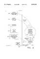
- FIG. 1illustrates a general method for interfacing a client computer to a network according to the prior art.
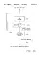
- FIG. 2illustrates a modified version of the ISO model representation of network protocol stacks as modified by the '735 patent in the prior art.
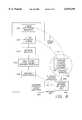
- FIG. 3illustrated the elements of the prior art that are replaced by the present invention.
- FIG. 4is a high level block diagram of the present invention generally.
- FIG. 5is an expanded block diagram of the network interface unit generally of the present invention.
- FIG. 6is an expanded block diagram of the protocol bridge generally of the present invention.
- FIG. 7is an illustration of one way to view the present invention in terms of the ISO reference model for protocol stacks.
- FIG. 8is a high level block diagram of the preferred embodiment of the present invention.
- FIG. 9is an expanded block diagram of the network interface unit of the preferred embodiment of the present invention.
- FIG. 10is an expanded block diagram of the protocol bridge of the preferred embodiment of the present invention.
- FIG. 11is a block diagram of the device management system of the present invention.
- FIG. 1show a client computer connected to a network as taught in the prior art.
- a client computer 100typically has one or more client application programs 160 executing on the client computer.
- the client application programs 160execute on the client computer 100, the application programs 160 and the client operating system 150 will often use network resources, including network devices and operating systems and other network objects 95 located on a network 190.
- the client computer 100is physically apart from the network devices 195, the program logic of client application programs 160 and client operating system 150 reference the network objects 195 as if they were local objects; this logical connection is represented in FIG. 1 by the logical links 170.
- the operating system 150When a client application program 160 or a client operating system 150 invoke an operation that utilizes network objects 195, the operating system 150 will typically present the request to the underlying network protocol 140 that is bound to the client operating system 150; the network protocol 140 is then presented to the network interface card (nic) driver 130.
- the role of the network driver 130is to translated the software-based protocols of the network protocol 140 into specific hardware commands recognized by the hardware network interface card 110.
- the network interface card (nic) 1 10then transmits the data over the physical link 180, typically a network wire, through the physical network connector 120 on the nic card 110.
- the datais presented to the network 190.
- the networkroutes the data to the appropriate device or other network object 195 that is the target of the command.
- Network trafficis generally bidirectional, and the network objects 195 generally responds by transmitting data to the client program 160 or client operating system 150 back through the same path.
- FIG. 2illustrates a prior art variation of the ISO reference model for networks stacks as described in the '736 patent.
- FIG. 2differs from the standard ISO reference model by the inclusion of an optimization layer 220 and 220'.
- the '736 patentteaches a model where the application program 190 of FIG. 1, represented as the application layer 270 in FIG. 2 communicates through the stack 280 to a physical link 200' which, in the '736 teachings can be a wireless link.
- layers 230, 240,250, 260are unmodified from their customary usage; layer 220 optimizes the customary network protocol 230 and the datalink traffic 210, eventually resulting in a physical wireless transmission to the physical layer 200' of a second protocol stack 280'.
- the '736 patentrelies on its ability to interface at the network level 230, and thus is sensitive to network level changes in layer 230.
- FIGS. 3 and 4are used to illustrate generally how the present invention differs from the prior art.
- FIG. 3identifies components altered or removed from the prior art versions to achieve the present invention.
- the network interface card 110 and the corresponding physical network connection 120, and the physical link 180are removed from the client computer 100.
- a pseudo nic driver 430In the place of the removed elements are a pseudo nic driver 430, a transparent link 410 and the corresponding transparent communications means 420.
- the transparent communication means 410communicates with a new network interface unit 440.
- the network interface unit 440communicates with the prior art network of FIG. 1 through a new physical link 450.
- the physical link 450 of the network interface unit 440is new, it is physically like the original physical link 180, and the network 190 does not need to be changed to recognize this new arrangement because the data present through physical link 450 follows the established network protocol 140, known by both the client application programs 160, the client operating system 150, the network 190 generally. Since the logical links 170 have been preserved without a need for modification, as well as the applications program 160, the client operating system 150, the network protocol 140, and the network 190, the enhanced client computer 400 operates like the client computer 100, yet is connected to the network in a novel way.
- Transparent link and the corresponding term transparent communication sare terms of art used here to designate the broad category of communication links and communication means based generally on easy to connect and disconnect technologies.
- Transparent linksinclude, but are not limited to traditional wireless technologies such as infrared transmissions and radio communications.
- the present inventionis applicable using any transparent link technology, known or new, dissimilar from traditional from hard-wire network cabling, that facilitates easy connection access to and easy disconnection from a network.
- the new network interface unit 440is shown in greater detail in FIG. 5.
- the network interface unit 440interfaces with the enhanced client computer 400 over the transparent link 410 using a transparent communication hardware means 515.
- the hardware means 515can be the same means as the client transparent communications hardware means 420, but it can be different as long as it correctly interfaces with the transparent link 410.
- the hardware means 515generally converts the data from the physical transparent link 410 and presents it bi-directionally to the protocol bridge 520.
- the implementation of the protocol bridge 520depends both on the choice of the transparent communications hardware means 515 and the choice of the specific network hardware means 530.
- the network interface hardware meansis a means to present the protocol to a network physical wire 190, and is generally a network interface chip (nic), well known in the art. Such chips are used in mass-market NIC cards.
- FIG. 6shows generally the protocol bridge 520 in more detail.
- the protocol bridgeconsists of three components: a bi-directional converter 610, and two drivers--a network hardware driver 600 and a transparent communications means driver 620.
- Each driveris a software component that talks to and manages its respective hardware.
- the converterhas the responsibility to both convert the data in a hardware sense, but to also compensate for differences between the transparent communication means and the network means.
- transparent meansare slower than networks.
- the converter 610often will be required to intelligently detect both overruns, and junk mail network traffic and in some cases discard network data packets presented by either means.
- the rules of which packets can be discardedare network protocol specific, but generally all network protocols allow packets to be lost in some situations, requiring a retransmission in most cases. If the converter is intelligent, it in some cases improves network performance.
- the particulars of how to generally implement such an optimizing converterare known in the prior art and are taught generally in the '736 patent.
- the '736 patenthas a model in which the client computer and the reception means for the wireless communication are represented as symmetric protocol stacks 280 and 280' in FIG. 2.
- FIG. 7illustrates how the present fits in the ISO reference model.
- the entire network interface unit 440, as well as the pseudo nic driver 430, the transparent communications hardware means 420, and the transparent link 410 itselfare all hidden within the data link, lower level than that taught by the '736 patent.
- the preferred embodiment of the present inventionis illustrated in FIGS. 8 through 10, and is presented for purposes of illustration rather than limitation.
- the transparent link 410 of FIG. 4is realized by the infrared link 810 of FIG. 8.
- the target network of the preferred embodimentis an Ethernet network, typically hosting TCP/IP and SP/IPX protocols as well as other popular protocols.
- the enhanced client computer 400is an infrared enhanced client computer 800 in the preferred embodiment. These clients are typically either manufactured with infrared capabilities built in, or, alternatively, infrared capabilities can be added with add-on hardware.
- the client environment for the preferred embodimentis Microsoft Windows, currently either Windows 95 or Windows NT.
- NDIS 4is a Microsoft NDIS driver 830 using a specific infrared point-to-point protocol described herein[4], called LAELMP for convenience.
- the NDIS specificationis well known in the art and is not detailed here.
- the NDIS and Microsoft modelgenerally follow the ISO reference model, but not exactly.
- NDISis lower on the ISO reference model and is protocol independent, unlike the data link level 210 of the traditional ISO model or the optimization level taught in the '736 patent.
- the present inventionby operating at a lower level in the ISO model than the ⁇ teaching of the 736 patent, achieves protocol independence.
- the LAELMP infrared protocol, disclosed herein,is a detailed specification showing how a client side driver, such as the NDIS driver 830 of FIG.
- the LAELMP protocolspecifies, among other things, how data connections are formed and how the channel is synchronized to avoid data loss through simultaneous transmission by both sides.
- the LAELMP protocolhas been offered to a public standards body and is expected to become a public standard for infrared connectivity products.
- FIG. 9show the preferred embodiment of the network interface unit 440 of FIG. 4, namely the infrared network interface unit 940 of FIG. 9.
- the transparent link 410is an infrared link 910.
- the transparent communications hardware means 515 in the preferred embodimentis an infrared transceiver 915 of FIG. 9, and is implemented with a infrared chip, the IBM 31T1502 infrared communications controller. The same part is used for the infrared transceiver 820 in FIG. 8.
- the protocol bridge 520 in the preferred embodimentis the infrared ethernet nic bridge 920 of FIG. 9.
- the bridge 920 in the preferred embodimentbi-directionally interfaces the infrared transceiver 915 with the nic chip 930.
- the nic chip 930is a commodity part well known in the art.
- the preferred embodimentsuses a National Semiconductor SNIC for the nic chip 930, part number DP83902AVLJ.
- the Ethernet physical connectors 850 in the preferred embodimentinclude both a 10BaseT RJ-45 connector and a 10BaseT2 BNC connector, allowing physical connection to the network by either RJ-45 twisted pair or widely used coax.
- the infrared-Ethernet nic protocol bridge 920is more fully illustrated.
- the NIC driver 1060 of FIG. 10is a customized driver.
- the methodology for writing such a driveris well known in the art once both interfaces are known.
- the nic chip 930is well specified by vendor documentation in the prior art; the LAELMP infrared protocol is specified herein, thus the method of building this driver are apparent to one skilled in the art of driver writing.
- the infrared transceiver driver 1020 of FIG. 9 of the preferred embodimentcan be built by one skilled in the art using well known method once both interface specifications are known and both are disclosed either here or in the prior art.
- the specifications for an infrared transceiver 915is well specified by the corresponding vendor documentation not included here.
- the LAELMP infrared protocol driver 1050is included herein, thus teaching one skilled in the art how to make such a driver.
- the LAELMP protocol driver 1050uses the same LAELMP protocol used in the NDIS driver 830 of FIG. 8 in the infrared enhanced client computer 800.
- the disclosure herein of LAELMP protocolis made to ensure one skilled in the art can write such a driver.
- the LAELMP driver 1050 of the preferred embodimentalso intelligently monitors network traffic.
- infrared traffictravels at a maximum rate of 15,000 bits per second.
- the Ethernet networkcan handle data at a rate of over 10,000,000 bits per second, nearly 100 times as fast.
- the Ethernet networkis serving multiple nodes, but the infrared channel is serving a single node.
- the converter 1010detects that infrared overload is imminent and discards packets in the following order: First packets known as broadcast packets are discarded. Next, address verification packets such as IPX RIPS and SAPS and IP arps are discarded. Finally, as a last resort, unicast packets designated for this node are discarded.
- the preferred embodiment of the infrared network interface unit 940 in FIG. 9also includes a device management system 1100 as shown in FIG. 11 to allow management of the network interface unit 940.
- the device management systemis generally described in the FIG. 11, and is omitted from FIG. 9. Since the novel design of the present invention hides the network interface unit 940 from the Ethernet network 190 generally, an additional management control path is needed. Network management protocols customarily are used to manage devices on a network 190, but since the network interface unit 440 of the present network is not recognized by the network as a separate unit, traditional SMNP over the network cannot be used.
- the present inventioninstead uses the infrared connectivity from infrared link 910 of FIG. 9 to provide management interface.
- the device management system 1100 in FIG. 11solves the problem in a novel way.
- the device management system 1100has a management client, typically Windows 95, and uses a connectionless management protocol such as SNMP.
- the present inventionintroduces a connectionless to connection converter 1130 and a corresponding optional connection to connectionless converter 1150 as shown in FIG. 11. This novel arrangement allows popular management protocols to be used in environments that do not support such protocols in the prior art.
- an infrared enhanced Windows 95 client 110can connect to a network interface unit 940 by infrared beam using SNMP management software based on the SNMP management protocol 120.
- the converter 1130is an SNMP to LAELMP converter encodes SNMP within LAELMP and which transparently makes a connection when necessary to the corresponding LAELMP driver 1050 in the network interface unit 940. It uses the LAELMP protocol to transmit the LAELMP encoded SNMP data to the unit 940.
- the corresponding converter 1250is in inside the network interface unit 940. It can either translate the data back to SNMP using the converter 1150 of FIG. 11, or it can simply parse the command directly and execute the management command using well known and customary management execution means 1170. SNMP return data is transmitted back to the client in an analogous fashion.
- Additional network media typessuch as token ring are contemplated.
- NDIS based pseudo nic driverIn addition to an NDIS based pseudo nic driver, other protocols including PPP and ODI are contemplated.
Landscapes
- Engineering & Computer Science (AREA)
- Computer Networks & Wireless Communication (AREA)
- Signal Processing (AREA)
- Computer Security & Cryptography (AREA)
- Small-Scale Networks (AREA)
- Communication Control (AREA)
Abstract
Description
Claims (1)
Priority Applications (1)
| Application Number | Priority Date | Filing Date | Title |
|---|---|---|---|
| US08/748,959US6070199A (en) | 1996-11-13 | 1996-11-13 | Apparatus to connect a client computer to a computer data network |
Applications Claiming Priority (1)
| Application Number | Priority Date | Filing Date | Title |
|---|---|---|---|
| US08/748,959US6070199A (en) | 1996-11-13 | 1996-11-13 | Apparatus to connect a client computer to a computer data network |
Publications (1)
| Publication Number | Publication Date |
|---|---|
| US6070199Atrue US6070199A (en) | 2000-05-30 |
Family
ID=25011635
Family Applications (1)
| Application Number | Title | Priority Date | Filing Date |
|---|---|---|---|
| US08/748,959Expired - LifetimeUS6070199A (en) | 1996-11-13 | 1996-11-13 | Apparatus to connect a client computer to a computer data network |
Country Status (1)
| Country | Link |
|---|---|
| US (1) | US6070199A (en) |
Cited By (24)
| Publication number | Priority date | Publication date | Assignee | Title |
|---|---|---|---|---|
| WO2002027422A3 (en)* | 2000-09-27 | 2002-08-15 | Chiang-Lung Huang | Beamcast (continuous data beaming system) |
| US6457049B2 (en) | 1998-06-08 | 2002-09-24 | Telxon Corporation | Enterprise wide software management system for integrating a plurality of heterogenous software systems to support clients and subclients communication by using a midware interface |
| US6473805B2 (en)* | 1998-06-08 | 2002-10-29 | Telxon Corporation | Method and apparatus for intergrating wireless and non-wireless devices into an enterprise computer network using an interfacing midware server |
| US6516352B1 (en)* | 1998-08-17 | 2003-02-04 | Intel Corporation | Network interface system and method for dynamically switching between different physical layer devices |
| US20030067884A1 (en)* | 1997-11-21 | 2003-04-10 | Abler Joseph Michael | Dynamic detection of LAN network protocol |
| US20030208652A1 (en)* | 2002-05-02 | 2003-11-06 | International Business Machines Corporation | Universal network interface connection |
| US20040024894A1 (en)* | 2002-08-02 | 2004-02-05 | Osman Fazil Ismet | High data rate stateful protocol processing |
| US20040054569A1 (en)* | 2002-07-31 | 2004-03-18 | Alvaro Pombo | Contextual computing system |
| US6711624B1 (en)* | 1999-01-13 | 2004-03-23 | Prodex Technologies | Process of dynamically loading driver interface modules for exchanging data between disparate data hosts |
| US6714990B1 (en)* | 1999-03-12 | 2004-03-30 | Nokia Mobile Phones Ltd. | Communication system and data adapter |
| US20040105122A1 (en)* | 2000-03-20 | 2004-06-03 | Schaeffer Richard J. | Printer control and document management system |
| US6892067B1 (en)* | 1999-12-30 | 2005-05-10 | Nokia Corporation | Script based interfaces for mobile phones |
| US20060080397A1 (en)* | 2004-10-08 | 2006-04-13 | Marc Chene | Content management across shared, mobile file systems |
| US20060123010A1 (en)* | 2004-09-15 | 2006-06-08 | John Landry | System and method for managing data in a distributed computer system |
| US20060161646A1 (en)* | 2005-01-19 | 2006-07-20 | Marc Chene | Policy-driven mobile forms applications |
| US7539760B1 (en) | 2003-09-12 | 2009-05-26 | Astute Networks, Inc. | System and method for facilitating failover of stateful connections |
| US7596621B1 (en) | 2002-10-17 | 2009-09-29 | Astute Networks, Inc. | System and method for managing shared state using multiple programmed processors |
| US7802001B1 (en) | 2002-10-18 | 2010-09-21 | Astute Networks, Inc. | System and method for flow control within a stateful protocol processing system |
| US7814218B1 (en) | 2002-10-17 | 2010-10-12 | Astute Networks, Inc. | Multi-protocol and multi-format stateful processing |
| US20110106949A1 (en)* | 2009-10-30 | 2011-05-05 | Cisco Technology, Inc. | Balancing Server Load According To Availability Of Physical Resources |
| US20110158652A1 (en)* | 2009-12-31 | 2011-06-30 | At&T Intellectual Property I, L.P. | Portable infrared control liaison |
| US8151278B1 (en) | 2002-10-17 | 2012-04-03 | Astute Networks, Inc. | System and method for timer management in a stateful protocol processing system |
| US8799242B2 (en) | 2004-10-08 | 2014-08-05 | Truecontext Corporation | Distributed scalable policy based content management |
| US10269000B2 (en)* | 2010-09-07 | 2019-04-23 | Revel Systems, Inc. | Point of sale system |
Citations (14)
| Publication number | Priority date | Publication date | Assignee | Title |
|---|---|---|---|---|
| US5099346A (en)* | 1988-01-27 | 1992-03-24 | Spectrix Corporation | Infrared communications network |
| US5410738A (en)* | 1991-09-03 | 1995-04-25 | Ncr Corporation | System and method for linking wireless local area networks |
| US5426637A (en)* | 1992-12-14 | 1995-06-20 | International Business Machines Corporation | Methods and apparatus for interconnecting local area networks with wide area backbone networks |
| US5446736A (en)* | 1993-10-07 | 1995-08-29 | Ast Research, Inc. | Method and apparatus for connecting a node to a wireless network using a standard protocol |
| US5477415A (en)* | 1993-11-12 | 1995-12-19 | Texas Instruments Incorporated | Automatic computer docking station having a motorized tray, cammed side connectors, motorized side connectors, and locking and unlocking guide pins |
| US5530963A (en)* | 1993-12-16 | 1996-06-25 | International Business Machines Corporation | Method and system for maintaining routing between mobile workstations and selected network workstation using routing table within each router device in the network |
| US5535338A (en)* | 1993-07-28 | 1996-07-09 | 3Com Corporation | Multifunction network station with network addresses for functional units |
| US5553076A (en)* | 1994-05-02 | 1996-09-03 | Tcsi Corporation | Method and apparatus for a wireless local area network |
| US5572528A (en)* | 1995-03-20 | 1996-11-05 | Novell, Inc. | Mobile networking method and apparatus |
| US5675740A (en)* | 1992-08-14 | 1997-10-07 | International Business Machines Corp. | System for sending messages in a session using a mixture of protocols and preventing usage of a protocol when the message failing to meet a set of criteria |
| US5717737A (en)* | 1995-06-01 | 1998-02-10 | Padcom, Inc. | Apparatus and method for transparent wireless communication between a remote device and a host system |
| US5734824A (en)* | 1993-02-10 | 1998-03-31 | Bay Networks, Inc. | Apparatus and method for discovering a topology for local area networks connected via transparent bridges |
| US5754552A (en)* | 1995-07-12 | 1998-05-19 | Compaq Computer Corporation | Automatic communication protocol detection system and method for network systems |
| US5857075A (en)* | 1995-01-11 | 1999-01-05 | Sony Corporation | Method and integrated circuit for high-bandwidth network server interfacing to a local area network |
- 1996
- 1996-11-13USUS08/748,959patent/US6070199A/ennot_activeExpired - Lifetime
Patent Citations (14)
| Publication number | Priority date | Publication date | Assignee | Title |
|---|---|---|---|---|
| US5099346A (en)* | 1988-01-27 | 1992-03-24 | Spectrix Corporation | Infrared communications network |
| US5410738A (en)* | 1991-09-03 | 1995-04-25 | Ncr Corporation | System and method for linking wireless local area networks |
| US5675740A (en)* | 1992-08-14 | 1997-10-07 | International Business Machines Corp. | System for sending messages in a session using a mixture of protocols and preventing usage of a protocol when the message failing to meet a set of criteria |
| US5426637A (en)* | 1992-12-14 | 1995-06-20 | International Business Machines Corporation | Methods and apparatus for interconnecting local area networks with wide area backbone networks |
| US5734824A (en)* | 1993-02-10 | 1998-03-31 | Bay Networks, Inc. | Apparatus and method for discovering a topology for local area networks connected via transparent bridges |
| US5535338A (en)* | 1993-07-28 | 1996-07-09 | 3Com Corporation | Multifunction network station with network addresses for functional units |
| US5446736A (en)* | 1993-10-07 | 1995-08-29 | Ast Research, Inc. | Method and apparatus for connecting a node to a wireless network using a standard protocol |
| US5477415A (en)* | 1993-11-12 | 1995-12-19 | Texas Instruments Incorporated | Automatic computer docking station having a motorized tray, cammed side connectors, motorized side connectors, and locking and unlocking guide pins |
| US5530963A (en)* | 1993-12-16 | 1996-06-25 | International Business Machines Corporation | Method and system for maintaining routing between mobile workstations and selected network workstation using routing table within each router device in the network |
| US5553076A (en)* | 1994-05-02 | 1996-09-03 | Tcsi Corporation | Method and apparatus for a wireless local area network |
| US5857075A (en)* | 1995-01-11 | 1999-01-05 | Sony Corporation | Method and integrated circuit for high-bandwidth network server interfacing to a local area network |
| US5572528A (en)* | 1995-03-20 | 1996-11-05 | Novell, Inc. | Mobile networking method and apparatus |
| US5717737A (en)* | 1995-06-01 | 1998-02-10 | Padcom, Inc. | Apparatus and method for transparent wireless communication between a remote device and a host system |
| US5754552A (en)* | 1995-07-12 | 1998-05-19 | Compaq Computer Corporation | Automatic communication protocol detection system and method for network systems |
Non-Patent Citations (6)
| Title |
|---|
| Infrared Data Transmission: The Missing Link by Lee Goldberg. Electronic Design Apr. 17, 1995 p. 47 to 52, 54 64.* |
| Infrared Data Transmission: The Missing Link? by Lee Goldberg. Electronic Design Apr. 17, 1995 p. 47 to 52, 54-64. |
| Optical Wireless Network for Office Communication. Takahashi, Osa Mu; Touge, Takashi. Telecommunications vol. 20, 1985/1986 p 217 228.* |
| Optical Wireless Network for Office Communication. Takahashi, Osa Mu; Touge, Takashi. Telecommunications vol. 20, 1985/1986 p 217-228. |
| Windows Magazine Jan. 94 by Jeni Boyce Title: Soho: Why Network Why Not p. 221 234.* |
| Windows Magazine Jan. 94 by Jeni Boyce Title: Soho: Why Network? Why Not! p. 221-234. |
Cited By (37)
| Publication number | Priority date | Publication date | Assignee | Title |
|---|---|---|---|---|
| US6928086B2 (en)* | 1997-11-21 | 2005-08-09 | International Business Machines Corporation | Dynamic detection of LAN network protocol |
| US20030067884A1 (en)* | 1997-11-21 | 2003-04-10 | Abler Joseph Michael | Dynamic detection of LAN network protocol |
| US6457049B2 (en) | 1998-06-08 | 2002-09-24 | Telxon Corporation | Enterprise wide software management system for integrating a plurality of heterogenous software systems to support clients and subclients communication by using a midware interface |
| US6473805B2 (en)* | 1998-06-08 | 2002-10-29 | Telxon Corporation | Method and apparatus for intergrating wireless and non-wireless devices into an enterprise computer network using an interfacing midware server |
| US20030131134A1 (en)* | 1998-06-08 | 2003-07-10 | Lewis Daniel E. | Method and apparatus for tracking transactions in an enterprise computer network |
| US7234002B2 (en) | 1998-06-08 | 2007-06-19 | Lewis Daniel E | Method and apparatus for tracking transactions in an enterprise computer network |
| US6516352B1 (en)* | 1998-08-17 | 2003-02-04 | Intel Corporation | Network interface system and method for dynamically switching between different physical layer devices |
| US6711624B1 (en)* | 1999-01-13 | 2004-03-23 | Prodex Technologies | Process of dynamically loading driver interface modules for exchanging data between disparate data hosts |
| US6714990B1 (en)* | 1999-03-12 | 2004-03-30 | Nokia Mobile Phones Ltd. | Communication system and data adapter |
| US6892067B1 (en)* | 1999-12-30 | 2005-05-10 | Nokia Corporation | Script based interfaces for mobile phones |
| US20040105122A1 (en)* | 2000-03-20 | 2004-06-03 | Schaeffer Richard J. | Printer control and document management system |
| WO2002027422A3 (en)* | 2000-09-27 | 2002-08-15 | Chiang-Lung Huang | Beamcast (continuous data beaming system) |
| US7171505B2 (en) | 2002-05-02 | 2007-01-30 | International Business Machines Corporation | Universal network interface connection |
| US20030208652A1 (en)* | 2002-05-02 | 2003-11-06 | International Business Machines Corporation | Universal network interface connection |
| US8655738B2 (en) | 2002-07-31 | 2014-02-18 | Rpx Corporation | Contextual computing system |
| US20040054569A1 (en)* | 2002-07-31 | 2004-03-18 | Alvaro Pombo | Contextual computing system |
| US20110153465A1 (en)* | 2002-07-31 | 2011-06-23 | Truecontext Corporation | Contextual computing system |
| US7930215B2 (en) | 2002-07-31 | 2011-04-19 | Truecontext Corporation | Contextual computing system |
| US8015303B2 (en) | 2002-08-02 | 2011-09-06 | Astute Networks Inc. | High data rate stateful protocol processing |
| US20040024894A1 (en)* | 2002-08-02 | 2004-02-05 | Osman Fazil Ismet | High data rate stateful protocol processing |
| US8151278B1 (en) | 2002-10-17 | 2012-04-03 | Astute Networks, Inc. | System and method for timer management in a stateful protocol processing system |
| US7596621B1 (en) | 2002-10-17 | 2009-09-29 | Astute Networks, Inc. | System and method for managing shared state using multiple programmed processors |
| US7814218B1 (en) | 2002-10-17 | 2010-10-12 | Astute Networks, Inc. | Multi-protocol and multi-format stateful processing |
| US7802001B1 (en) | 2002-10-18 | 2010-09-21 | Astute Networks, Inc. | System and method for flow control within a stateful protocol processing system |
| US7539760B1 (en) | 2003-09-12 | 2009-05-26 | Astute Networks, Inc. | System and method for facilitating failover of stateful connections |
| US20060123010A1 (en)* | 2004-09-15 | 2006-06-08 | John Landry | System and method for managing data in a distributed computer system |
| US8090844B2 (en) | 2004-10-08 | 2012-01-03 | Truecontext Corporation | Content management across shared, mobile file systems |
| US20060080397A1 (en)* | 2004-10-08 | 2006-04-13 | Marc Chene | Content management across shared, mobile file systems |
| US8799242B2 (en) | 2004-10-08 | 2014-08-05 | Truecontext Corporation | Distributed scalable policy based content management |
| US9471611B2 (en) | 2004-10-08 | 2016-10-18 | ProntoForms Inc. | Distributed scalable policy based content management |
| US7774504B2 (en) | 2005-01-19 | 2010-08-10 | Truecontext Corporation | Policy-driven mobile forms applications |
| US20060161646A1 (en)* | 2005-01-19 | 2006-07-20 | Marc Chene | Policy-driven mobile forms applications |
| US20110106949A1 (en)* | 2009-10-30 | 2011-05-05 | Cisco Technology, Inc. | Balancing Server Load According To Availability Of Physical Resources |
| US9122537B2 (en)* | 2009-10-30 | 2015-09-01 | Cisco Technology, Inc. | Balancing server load according to availability of physical resources based on the detection of out-of-sequence packets |
| US20110158652A1 (en)* | 2009-12-31 | 2011-06-30 | At&T Intellectual Property I, L.P. | Portable infrared control liaison |
| US8233802B2 (en) | 2009-12-31 | 2012-07-31 | At&T Intellectual Property I, L.P. | Portable infrared control liaison |
| US10269000B2 (en)* | 2010-09-07 | 2019-04-23 | Revel Systems, Inc. | Point of sale system |
Similar Documents
| Publication | Publication Date | Title |
|---|---|---|
| US6070199A (en) | Apparatus to connect a client computer to a computer data network | |
| US5553075A (en) | Packet data protocol for wireless communication | |
| US6154464A (en) | Physical layer device having a media independent interface for connecting to either media access control entitices or other physical layer devices | |
| US6516352B1 (en) | Network interface system and method for dynamically switching between different physical layer devices | |
| US5953507A (en) | Method and apparatus for providing a 3-way connection between a mobile computing device, a stationary computing device and a computer network | |
| US6226676B1 (en) | Connection establishment and termination in a mixed protocol network | |
| US6169729B1 (en) | 200 Mbps PHY/MAC apparatus and method | |
| US5917629A (en) | Transceiver for extending a CSMA/CD network for wireless communication | |
| US6618359B1 (en) | Error recovery in a mixed protocol networks | |
| US6922548B1 (en) | Providing remote network driver interface specification services over a wireless radio-frequency medium | |
| KR100389922B1 (en) | Auto-negotiation method for high speed link in gigabit ethernet using 1000base-t standard and apparatus thereof | |
| US20040208180A1 (en) | System and method for supporting auto-negotiation among standards having different rates | |
| US6320874B1 (en) | Establishing and terminating connections in a mixed protocol network | |
| US7584313B1 (en) | Method and system for connecting a wireless USB host and a wired USB device | |
| JP2003188926A (en) | Ethernet device and method for expanding ethernet FIFO buffer | |
| AU751233B2 (en) | Parallel backplane physical layer interface with scalable data bandwidth | |
| US6765878B1 (en) | Selective use of transmit complete interrupt delay on small sized packets in an ethernet controller | |
| US6496509B1 (en) | System for transmitting data packets between computers via an IEEE-1394 network medium | |
| US5938731A (en) | Exchanging synchronous data link control (SDLC) frames to adjust speed of data transfer between a client and server | |
| US6363432B1 (en) | Media independent interface between IEEE 802.3 (ethernet) based physical layer devices | |
| EP1505759B1 (en) | Method and device for transmitting/receiving data using acknowledged transport layer protocols | |
| US6674742B1 (en) | Automatic SDLC role configuration on router interfaces | |
| US20050273541A1 (en) | Circuit and method for adaptively recognizing a data packet in a universal serial bus network device | |
| KR100320739B1 (en) | Ieee 1394 system for long distance connection and embodying method thereof | |
| EP1337928B1 (en) | Network and method for invisible proxy and hooking systems with wireless communication |
Legal Events
| Date | Code | Title | Description |
|---|---|---|---|
| AS | Assignment | Owner name:EXTENDED SYSTEMS, INC., IDAHO Free format text:ASSIGNMENT OF ASSIGNORS INTEREST;ASSIGNORS:AXTMAN, DANIEL P.;BOOBAR, CRAIG K.;HUTCHISON, VANESSA L.;AND OTHERS;REEL/FRAME:008787/0834;SIGNING DATES FROM 19970630 TO 19970711 | |
| STCF | Information on status: patent grant | Free format text:PATENTED CASE | |
| AS | Assignment | Owner name:SILICON VALLEY BANK, CALIFORNIA Free format text:SECURITY AGREEMENT;ASSIGNOR:EXTENDED SYSTEMS INCORPORATED;REEL/FRAME:012775/0397 Effective date:20020409 | |
| FPAY | Fee payment | Year of fee payment:4 | |
| AS | Assignment | Owner name:EXTENDED SYSTEMS INCORPORATED, IDAHO Free format text:RELEASE;ASSIGNOR:SILICON VALLEY BANK;REEL/FRAME:018606/0765 Effective date:20061101 | |
| FPAY | Fee payment | Year of fee payment:8 | |
| FEPP | Fee payment procedure | Free format text:PAT HOLDER NO LONGER CLAIMS SMALL ENTITY STATUS, ENTITY STATUS SET TO UNDISCOUNTED (ORIGINAL EVENT CODE: STOL); ENTITY STATUS OF PATENT OWNER: LARGE ENTITY | |
| SULP | Surcharge for late payment | ||
| FPAY | Fee payment | Year of fee payment:12 |