US6069698A - Optical imaging apparatus which radiates a low coherence light beam onto a test object, receives optical information from light scattered by the object, and constructs therefrom a cross-sectional image of the object - Google Patents
Optical imaging apparatus which radiates a low coherence light beam onto a test object, receives optical information from light scattered by the object, and constructs therefrom a cross-sectional image of the objectDownload PDFInfo
- Publication number
- US6069698A US6069698AUS09/141,430US14143098AUS6069698AUS 6069698 AUS6069698 AUS 6069698AUS 14143098 AUS14143098 AUS 14143098AUS 6069698 AUS6069698 AUS 6069698A
- Authority
- US
- United States
- Prior art keywords
- transmission time
- imaging apparatus
- optical
- sample
- single mode
- Prior art date
- Legal status (The legal status is an assumption and is not a legal conclusion. Google has not performed a legal analysis and makes no representation as to the accuracy of the status listed.)
- Expired - Lifetime
Links
Images


Classifications
- G—PHYSICS
- G01—MEASURING; TESTING
- G01B—MEASURING LENGTH, THICKNESS OR SIMILAR LINEAR DIMENSIONS; MEASURING ANGLES; MEASURING AREAS; MEASURING IRREGULARITIES OF SURFACES OR CONTOURS
- G01B9/00—Measuring instruments characterised by the use of optical techniques
- G01B9/02—Interferometers
- G01B9/02055—Reduction or prevention of errors; Testing; Calibration
- G01B9/02062—Active error reduction, i.e. varying with time
- G01B9/02067—Active error reduction, i.e. varying with time by electronic control systems, i.e. using feedback acting on optics or light
- G01B9/02069—Synchronization of light source or manipulator and detector
- A—HUMAN NECESSITIES
- A61—MEDICAL OR VETERINARY SCIENCE; HYGIENE
- A61B—DIAGNOSIS; SURGERY; IDENTIFICATION
- A61B5/00—Measuring for diagnostic purposes; Identification of persons
- A61B5/0059—Measuring for diagnostic purposes; Identification of persons using light, e.g. diagnosis by transillumination, diascopy, fluorescence
- A61B5/0062—Arrangements for scanning
- A61B5/0066—Optical coherence imaging
- A—HUMAN NECESSITIES
- A61—MEDICAL OR VETERINARY SCIENCE; HYGIENE
- A61B—DIAGNOSIS; SURGERY; IDENTIFICATION
- A61B5/00—Measuring for diagnostic purposes; Identification of persons
- A61B5/0059—Measuring for diagnostic purposes; Identification of persons using light, e.g. diagnosis by transillumination, diascopy, fluorescence
- A61B5/0082—Measuring for diagnostic purposes; Identification of persons using light, e.g. diagnosis by transillumination, diascopy, fluorescence adapted for particular medical purposes
- A61B5/0084—Measuring for diagnostic purposes; Identification of persons using light, e.g. diagnosis by transillumination, diascopy, fluorescence adapted for particular medical purposes for introduction into the body, e.g. by catheters
- G—PHYSICS
- G01—MEASURING; TESTING
- G01B—MEASURING LENGTH, THICKNESS OR SIMILAR LINEAR DIMENSIONS; MEASURING ANGLES; MEASURING AREAS; MEASURING IRREGULARITIES OF SURFACES OR CONTOURS
- G01B9/00—Measuring instruments characterised by the use of optical techniques
- G01B9/02—Interferometers
- G01B9/02049—Interferometers characterised by particular mechanical design details
- G01B9/0205—Interferometers characterised by particular mechanical design details of probe head
- G—PHYSICS
- G01—MEASURING; TESTING
- G01B—MEASURING LENGTH, THICKNESS OR SIMILAR LINEAR DIMENSIONS; MEASURING ANGLES; MEASURING AREAS; MEASURING IRREGULARITIES OF SURFACES OR CONTOURS
- G01B9/00—Measuring instruments characterised by the use of optical techniques
- G01B9/02—Interferometers
- G01B9/02055—Reduction or prevention of errors; Testing; Calibration
- G01B9/02062—Active error reduction, i.e. varying with time
- G01B9/02064—Active error reduction, i.e. varying with time by particular adjustment of coherence gate, i.e. adjusting position of zero path difference in low coherence interferometry
- G—PHYSICS
- G01—MEASURING; TESTING
- G01B—MEASURING LENGTH, THICKNESS OR SIMILAR LINEAR DIMENSIONS; MEASURING ANGLES; MEASURING AREAS; MEASURING IRREGULARITIES OF SURFACES OR CONTOURS
- G01B9/00—Measuring instruments characterised by the use of optical techniques
- G01B9/02—Interferometers
- G01B9/0209—Low-coherence interferometers
- G01B9/02091—Tomographic interferometers, e.g. based on optical coherence
- A—HUMAN NECESSITIES
- A61—MEDICAL OR VETERINARY SCIENCE; HYGIENE
- A61B—DIAGNOSIS; SURGERY; IDENTIFICATION
- A61B5/00—Measuring for diagnostic purposes; Identification of persons
- A61B5/0059—Measuring for diagnostic purposes; Identification of persons using light, e.g. diagnosis by transillumination, diascopy, fluorescence
- A61B5/0082—Measuring for diagnostic purposes; Identification of persons using light, e.g. diagnosis by transillumination, diascopy, fluorescence adapted for particular medical purposes
- A61B5/0084—Measuring for diagnostic purposes; Identification of persons using light, e.g. diagnosis by transillumination, diascopy, fluorescence adapted for particular medical purposes for introduction into the body, e.g. by catheters
- A61B5/0086—Measuring for diagnostic purposes; Identification of persons using light, e.g. diagnosis by transillumination, diascopy, fluorescence adapted for particular medical purposes for introduction into the body, e.g. by catheters using infrared radiation
- G—PHYSICS
- G01—MEASURING; TESTING
- G01B—MEASURING LENGTH, THICKNESS OR SIMILAR LINEAR DIMENSIONS; MEASURING ANGLES; MEASURING AREAS; MEASURING IRREGULARITIES OF SURFACES OR CONTOURS
- G01B2290/00—Aspects of interferometers not specifically covered by any group under G01B9/02
- G01B2290/35—Mechanical variable delay line
- G—PHYSICS
- G01—MEASURING; TESTING
- G01B—MEASURING LENGTH, THICKNESS OR SIMILAR LINEAR DIMENSIONS; MEASURING ANGLES; MEASURING AREAS; MEASURING IRREGULARITIES OF SURFACES OR CONTOURS
- G01B2290/00—Aspects of interferometers not specifically covered by any group under G01B9/02
- G01B2290/65—Spatial scanning object beam
Definitions
- This inventionrelates to an optical imaging apparatus which radiates a low coherence light beam onto a test object, receives optical information from light scattered by the object, and constructs therefrom a cross-sectional image of the object.
- optical CT apparatuseswhich provide optical information regarding the internal structure of that tissue, in addition to imaging apparatuses which provide optical information regarding the surface condition of that tissue.
- the optical CT apparatusprovides cross-sectional images of a living body by delivering pulses with a duration of some pico-seconds, thereby obtaining the information of its internal structure, but a laser light source which is required for delivering such ultra-short pulses with a duration of pico-second order is expensive, large in size and cumbersome for handling.
- interference type OCToptical coherence tomography
- the probewhen it is used in a body cavity, to operate in conjunction with an endoscope. In such case, it would be convenient if the probe could be inserted through a forceps channel of that endoscope. But, no previous apparatuses have been so designed as to allow their adjunct probes to be exchanged as appropriate according to the length of forceps channel of an endoscope to be used in cooperation.
- the object of this inventionis to provide an optical imaging apparatus which can securely obtain cross-sectional images of a test object even after optical probes are exchanged.
- Another object of this inventionis to provide an optical imaging apparatus which not only allows the optical probe to be sufficiently slender to be inserted in a body cavity, but also ensures acquisition of high-resolution optical cross-sectional images of a test object.
- a further object of this inventionis to provide an optical imaging apparatus which not only enables the insert to be thinned, but also ensures a stable optical scanning, thereby obtaining stable cross-sectional images based on the stable optical scanning.
- optical imaging apparatus of this inventioncomprising:
- a light sourceto generate a low coherence light beam
- an optical probeincorporating a sample beam transmitting means made of a single-mode fiber which transmits the sample beam comprising said low coherence light beam to be radiated onto a test object, and the sample beam reflected by the test object;
- a detecting meanswhich is reversibly attached to said optical probe through an optical connector, allows said reflected beam and the reference beam comprising said low coherence light beam to interfere with each other, and detects an interference fringe resulting from the interference;
- an image signal generating meansto generate image signals based on signals provided by said detecting means
- a first transmission time altering meanswhich alters the transmission time of reference beam in accordance with the scanning range so that the interference position between said reflected beam and reference beam is scanned in the axial direction with respect to the optical axis;
- a second transmission time altering meanswhich alters the transmission time of the reference beam in accordance with the length of light path of said sample beam transmitting means
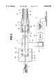
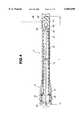
- FIGS. 1 to 5relate to the first embodiment of this invention: FIG. 1 shows the composition of an optical imaging apparatus representing the first embodiment of this invention; FIG. 2 shows an endoscope through which the first embodiment is inserted; FIG. 3 shows the rear end of optical scanning probe device constituting the first embodiment; FIG. 4 shows the overall composition of optical scanning probe device; and FIG. 5 shows the composition of a variation of the light path length altering means.
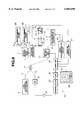
- FIGS. 6 to 8relate to the second embodiment of this invention: FIG. 6 shows the composition of an optical imaging apparatus representing the second embodiment of this invention; FIG. 7 gives a flat view of a light path modifying means; and FIG. 8 gives a sectional view of the same cut along line A-A' of FIG. 7.
- FIGS. 9 to 10relate to the third embodiment of this invention: FIG. 9 shows the composition of an optical imaging apparatus representing the third embodiment of this invention; and FIG. 10 shows the structure of an optical delay line.
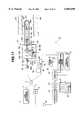
- FIGS. 11 to 14relate to the fourth embodiment of this invention: FIG. 11 shows the composition of an optical imaging apparatus representing the fourth embodiment of this invention; FIG. 12 shows the structure of the handle of probe of a first variation; FIG. 13 shows the composition of the tip of a beam scanning probe of a second variation; and FIG. 14 shows the mechanism how the light path is altered in a third variation.
- FIGS. 15 and 16relate to the fifth embodiment of this invention: FIG. 15 shows the composition of the tip of beam scanning probe; and FIG. 16 shows the composition of a scanning device mounted to the tip of beam scanning probe of FIG. 15.
- FIGS. 17 to 19relate to the sixth embodiment of this invention: FIG. 17 shows the composition of the tip of beam scanning probe; FIG. 18 shows the composition of a piezo-electric actuator to move the entire scanning unit body; and FIG. 19 gives graphs to illustrate how the scanning unit of FIG. 17 operates.
- FIGS. 20 and 21relate to the seventh embodiment of this invention: FIG. 20 gives a sectional view to illustrate the tip of beam scanning probe device; and FIG. 21 gives a sectional view to illustrate the tip of a variation of beam scanning prove device of FIG. 20.
- An optical imaging apparatus 1Aincludes a low coherence light source 2 such as a super-bright light emitting diode (to be abbreviated as SLD hereinafter).
- This low coherence light source 2is characterized by giving a low coherence light beam which is so resistive to interference that, assumed that it has a wavelength, for example, of 1300 nm, it narrowly presents an interference only when the distance difference to cause an interference exceeds a magnitude as small as, say, 17 ⁇ m. Let's illustrate it taking an example. Assume that the beam from this source is split into two components to take different light paths, and the two are recombined later.
- the two beamsare detected as beams interfering with each other, while when the two light paths in question are separated by more than above range, the two beams do not interfere with each other.
- a beam from this low coherence light source 2is incident on one tip of a first single mode fiber 3, and is transmitted to the other end (outward end surface).
- This first single mode fiber 3is optically connected with a second single mode fiber 5 at an optical coupler 4 inserted midway. Hence, the beam is split into two components at this optical coupler and the components are then transmitted separately.
- first single mode fiber 3Into the outward tip (away from the optical coupler 4) of first single mode fiber 3, is inserted an optical rotary joint 6 with a non-rotary section and a rotary section which establishes a connection permitting the transmission of light; to the outward tip of a third single mode fiber passing through the optical rotary joint 6 is reversibly attached a connector 9 of a beam scanning probe 8; and into the beam scanning probe 8 is inserted a fourth single mode fiber 10 which is driven into rotation; and the beam from the low coherence light source 2 is transmitted (guided) through the fourth single mode fiber 10.
- the thus transmitted beamemanates from the outward tip of beam scanning probe 8 to radiate onto a biological tissue 11 while scanning over the latter.
- a part of the reflected rays scattered from the surface of or from the interior of biological tissue 11is picked up by the same probe to be sent back along the same path to the first single mode fiber 3 where a part of the reflected beam is transferred to the second single mode fiber 5 by the optical coupler 4; and that part, emanating from one end of second single mode fiber 5 and is incident on, for example, a photo diode serving as a photosensitive detector.
- the rotary section of optical rotary jointis put into rotation by a rotary driving unit 13.
- the second single mode fiber 5has, on the outward side from the optical coupler 4, a light path modifying mechanism 14 which alters the light path for the reference beam.
- This light path modifying mechanismhas a first light path modifying means which speedily modifies the light path in accordance with the scan range when a biological tissue 11 is scanned by the beam scanning probe 8 for a specified length in the depth direction, and a second light path modifying means which, when beam scanning probes 8 having varying lengths are exchanged, can modify the length of the light path in accordance with the given variation to absorb that variation.
- a grating 16is placed opposite to the tip of second single mode fiber 5 with a lens 15 in between; placed opposite to the grating (diffraction grating) 16 with a lens 17 in between is a uniaxial stage 18 which can freely move in the direction of the light path, thereby to modify the length of the light path as indicated by the symbol a in the figure; on the uniaxial stage 18 is mounted a galvanometer mirror 19 or an element of the first light path modifying means which can rotate by a minute angle; and this galvanometer mirror 19 readily rotates under the control of a galvanometer controller 20 in the directions indicated by the symbol b.
- This galvanometer mirror 19is implemented to reflect light with the mirror of galvanometer which, when given a driving signal comprising an alternating current, puts into fast rotatory vibrations the mirror which is fixed to its movable part.
- the light path taken by the beam emanating from the end of second single mode fiber 5, and reflected by the galvanometer mirror 19alters, through these rotatory vibrations, by a specified amount in correspondence with the depth by which a biological tissue 11 is scanned.
- the galvanometer mirror 19acts as a first light path modifying means which is necessary for acquisition of cross-sectional images of a tissue in the direction of depth.
- the light path modifying means based on the galvanometer mirror 19is disclosed in SCIENCE, Vol. 276, 1997, pp. 2037-2039.
- the uniaxial stage 18further includes the second light path modifying means which reversibly adjusts the length of light path with a sufficient adjustable range to absorb the variation in length of individual beam scanning probes when probes are exchanged; and the same executes an offset control function to collect an image from a desired position by appropriately adjusting the light path.
- the second light path modifying meanswhich reversibly adjusts the length of light path with a sufficient adjustable range to absorb the variation in length of individual beam scanning probes when probes are exchanged; and the same executes an offset control function to collect an image from a desired position by appropriately adjusting the light path.
- This uniaxial stage 18has a motor for movement, and can move in the direction as indicated by the symbol a in the figure by applying a driving signal to the motor via a position control unit 21.
- the beam whose light path has been modified by this light path modifying mechanism 14is combined with the beam leaked from the first single mode fiber 3 at the coupler 4 placed at midway of second single mode fiber 5, and the two beams are received together by a photo diode 12.
- the second single mode fiber 5is constructed such that, when the uniaxial stage 18 is placed in the middle of its movable range, the light path one beam takes from the optical coupler 4 through the fourth single mode fiber 9 and the beam scanning probe 8 to a biological tissue 11 is comparable in length to that of the light path the other beam takes, after having passed through the second single mode fiber 5 and been reflected by the galvanometer mirror 19 on the uniaxial stage 18.
- the uniaxial stage 18is adjusted in position in accordance with the beam scanning probe 8 being currently used, thereby to absorb the variation in length inherent to this particular beam scanning probe 8; at the same time the galvanometer mirror 19 is put into rapid rotations or vibrations thereby to alter the light path of reference beam periodically; and thus the beam reflected from a certain desired spot of the biological tissue 11 in the direction of depth whose light path is nearly equal to the path of reference beam will interfere with the reference beam while beams reflected from other spots of the same biological tissue different in depth will not interfere with the reference beam.
- the beams received by aforementioned photo diode 12undergo a photo-electric conversion to produce a signal which is, after being amplified by an amplifier 22, delivered to a demodulator 23.
- the demodulator 23executes a demodulation treatment to extract signal components contained only in the beams interfering each other, and the output is fed through an A/D converter 24 to a computer 25.
- the computer 25produces imaging data representing a tomographic image, and delivers them to a monitor 26 thereby to cause the monitor to display an OCT image 27 on its display surface.
- the computer 25is connected to a position control unit 21 and controls the position of uniaxial stage 18 via the position control unit 21.
- the computer 25is also connected to a video synchronization circuit 28, and stores tomographic image data into an internal memory in synchrony with video synchronization signals generated during the formation of images.
- the video synchronization signals generated by the video synchronization circuit 28are delivered to both of the galvanometer controller 20 and rotary driving unit 13; the galvanometer controller 20, for example, generates driving signals in synchrony with the video synchronization signals (more concretely, with, of the two kinds of video synchronization signals including fast and slow signals, first fast video signals) while the rotary driving unit 13 generates driving signals in synchrony with the video synchronization signals (more concretely, with second slow video synchronization signals), thereby to put the rotary driving unit 13 into rotation and to scan the beam spot in the circular direction.
- the beam scanning probe 8 of the first embodimentcan be inserted from the forceps insertion port 32 of an endoscope 31 into a forceps insertion channel and its tip can be protruded from the opening prepared on the outward tip of the same channel.
- This endoscope 31has such a slender insert 33 that the insertion of its tip into a bodily cavity may be achieved easily, and at the rear end of this insert 33 is provided a thickened handle 34. Close to the rear end of this insert 33 is prepared the forceps insertion port 32, and the forceps insertion port 32 communicates with the forceps insertion channel.
- a light guide not illustrated hereis inserted into the insert 33; the light receiving end thereof is connected with a light source; and light from the latter is allowed to emanate from an illumination window prepared at the tip of insert 33 to illumine a lesion to be examined or the like. Further, an observation window is prepared close to the illumination window; and to the observation window is connected an object observing optical system so that one can observe the lesion illumined in the manner as described above through the optical system.
- the beam scanning probe 8radiates a low coherence light beam on a part of interest of a biological tissue such as a lesion, collects data for tomographic images of the interior of biological tissue, and delivers them for processing so that an OCT image 27 thereof is displayed on the display surface of monitor 26.
- first single mode fiber 3is optically coupled with fourth single mode fiber 10 inserted into the beam scanning probe 8 through the third single mode fiber 7 staying in the optical rotary joint 6 shown in FIG. 3.
- the first single mode fiber 3has a rotor socket 36 at its tip; to the concavity of rotor socket 36 is fitted a rotor 37; and the rotor 37 is held by two bearings 38 inserted between above two elements rotatably (with respect to the bearings 36 which remain motionless).
- the rotor 37is also connected, for example through a belt 41, to the pulley 43 of a motor which forms an element of the rotary driving unit 13.
- the motor 42When the motor 42 is put into rotation, the rotor 37 is also put into rotation as indicated by arrow c in the figure and the third single mode fiber 7 is put to rotation in association.
- the motor 42rotates at a constant speed being governed by motor driving signals provided by a rotation controller 44.
- the beam scanning probe 8puts the fourth single mode fiber 10 along the central axis of slender, cylindrical sheath 47 which acts as an outer tube of the probe; the rear and front ends of fourth single mode fiber 10 are fixed respectively to the connector body 48 and the tip body 49; and the fourth single mode fiber 10 is covered with a flexible shaft 50 which is made of a hollow, soft material to transmit a rotatory force.
- the inner diameter of this flexible shaft 50is slightly larger than the outer diameter of fourth single mode fiber 10.
- the fourth single mode fiber 10has a core diameter of, for example, about 9 ⁇ m.
- the sheath 47is made of a transparent, light transmissive (to a low coherence light beam) tube composed, for example, of polymethyl pentane, polyamide, FEP, TPFE, PFA or the like.
- the flexible shaft 50is a coil which is composed of a wire densely wound in a duplicate or triplicate manner, has a flexibility, and is capable of efficiently transmitting a force applied to one end of it to the other.
- the rear and front ends of this flexible shaft 50are also fixed to the connector body 48 and tip body 49, respectively.
- This connector body 48has projections 53 on its rear end; the rotor 37 has cavities 54 on its front end which are to engage with the projections 53.
- the connector body 48is also put into rotation. This rotatory force is conferred to the rear end of flexible shaft 50, transmitted through the flexible shaft body 50 down to its tip, and used to rotate the tip body 49 attached to the same tip.
- the tip of fourth single mode fiber 10is inserted through the hole prepared along the central axis of tip body 49 and fixed there with an adhesive or the like; and the front port prepared on the front end surface of fourth single mode fiber 10 is slightly widened to receive a cell foc lens 56 (GRIN lens) to converge rays emanating from the front end of fourth single mode fiber 10 onto a specified position.
- a cell foc lens 56GRIN lens
- the prismis fixed with an adhesive or the like.
- the beamhas a flux diameter of about 10 to 30 ⁇ m at a focusing point having a specified distance.
- the fourth single mode fiber 10has its front end cut obliquely, to prevent light directly reflected by the rear surface of GRIN lens 56 from entering that front end.
- Anti-reflection films 59consisting of an anti-reflection material are formed on the rear surface of the GRIN lens 56 and on the front surface of micro prism 57, to suppress light reflected from those surfaces.
- the sheath 47has its tip shaped like a semicircle and closed.
- the beam scanning probe 8 of this examplehas a total length of about 2000 mm, and the sheath has a diameter of 2.4 mm.
- Illuminating light generated by an endoscope light source not illustrated hereis guided by the light guide of endoscope 31, to illumine a biological tissue 11 from the illumination window prepared at the tip of insert 33.
- Light carrying the image of biological tissue 11 thus illuminedpasses through the observation window, and is focused through the object observing optical system onto a solid image fixing element; and processed by the video processor to present an endoscopic image on the display monitor.
- the beam scanning probe 8is inserted into a forceps insertion port 32 of an endoscope 31 as shown in FIG. 2, and is allowed to pass through the forceps channel until its tip protrudes from the tip of the latter.
- the connector 9 at the rear end of beam scanning probe 8is connected to the rotor 37 at the front end of optical rotary joint 6; then the optical imaging apparatus 1A as depicted in FIG. 1 is completed ready for use.
- the light pathmay vary slightly according to individual variations in length of beam scanning probes 8 when they are exchanged for each other. Even if, under this condition, the galvanometer mirror 19 is put into rotatory vibrations being triggered by driving signals from the galvanometer controller 20; the light path of reference beam reflected by the galvanometer mirror 19 is altered rapidly and periodically therewith; and tomographic image data of a biological tissue 11 in the depth direction are obtained, a number of difficulties will be encountered because the light path of beam scanning probe 8 and the light path of reference beam are not properly adjusted with respect to each other.
- tomographic image data of a tissue 11are obtained only when the light path falls in the middle of adjustable range (because the sample beam reflected from a too shallow surface level does not fall in the range where interfere with the reference beam reflected by the galvanometer mirror 19 is possible, and hence does not provide tomographic image data thereof) or conversely the sample beam reflected from a too deep level will not provide tomographic image data thereof for the same reason.
- the computer 25moves via the position control unit 21 the uniaxial stage 18 as appropriate in the directions as indicated by symbol a in the figure. To put it concretely, it moves the stage so that the light path is gradually lengthened from the shortest position (with regard to the apparatus of FIG. 1, the stage is shifted from left to right). During this operation, the galvanometer mirror 19 is put into speedy rotatory vibrations as in ordinary operation.
- interference pattern representative of the structure of tissue 11is detected as soon as the light path the reference beam takes is sufficiently equal in length to that of the beam on the side of the beam scanning probe 8; the interference pattern is displayed as OCT images 27 of the tissue 11 on the monitor 26, and the OCT images on display become increasingly widened.
- the operatorfeeds a command by striking appropriate keys on a key board not illustrated here to the computer to halt the further movement of uniaxial stage 18.
- the fourth single mode fiber 10 placed along the central axis of the probeis put into rotation, thereby to rotate the GRIN lens 56 and the micro prism 57 fixed to its outward tip in association, and this makes it possible to securely scan a low coherence light beam in the direction perpendicular to the central axis of beam scanning probe 8, and thus to ensure a secure acquisition of tomographic images in the direction of depth and having a radial extension in a two-dimensional space.
- the lateral surface of outward tip of beam scanning probe 8is placed close to the part of interest (for example, the lateral surface of outward tip of beam scanning probe 8 is placed nearly parallel to the part of interest); the part is scanned radially; and tomographic images thereof are collected in the manner as described above.
- the apparatusmay be modified such that the rotation speed (scanning speed in other words) can vary according to given observation conditions, for example, where tomographic images of a lesion extending radially in a circle are required, or where tomographic images of a lesion extending in a limited arc are required.
- the light path modifying means of the first embodimentconsists of the uniaxial stage 18, and the galvanometer mirror 19 installed in that uniaxial stage.
- the same functionmay be achieved without the use of uniaxial stage, as seen from the variant light path modifying means 14' shown in FIG. 5, which achieves the same object by following means.
- a mirror 61 like a triangular prismis inserted on the light path between the lens 17 and the galvanometer mirror 19; another reflective mirror 62 is placed on the light path which a beam would take when reflected by either one of the inclined surfaces of mirror 61; the mirror 62 is moved in the directions as indicated by symbol e along the light path formed between itself and the mirror 61 placed opposite, being triggered by a driving signal applied to a linear actuator 63; and therewith the variation in light path length may be absorbed each time beam scanning probes 8 are exchanged.
- the uniaxial stage 18moves the galvanometer mirror 19, or alternatively the linear actuator 63 moves the mirror 62 through an electrical driving signal, the movement in question may take place manually.
- the optical imaging apparatus 1B of the second embodiment as shown in FIG. 6employs a more widely applicable transmission time altering mechanism 64 having a different composition from the light path modifying means used by the optical imaging apparatus 1A of the first embodiment shown in FIG. 1 to modify the light path length of reference beam.
- the outward tip of second single mode fiber 5is wound around a disc-like piezo element 65 which serves as a first transmission time altering means; the outward end is allowed to extend from the piezo element 65; a lens 66 is placed opposite to that outward end; and opposite to this lens 66 is placed a mirror 67 installed in a uniaxial stage 18 which serves as a second transmission time altering means.
- the uniaxial stage 18is to absorb individual differences in light path length of beam scanning probes 8; its moving distance can be adjusted by the position control unit 21; and the piezo element receives a driving signal comprising an alternating current from the driving unit 68.
- the piezo element 65 around which the second single mode fiber 5 has been woundhas electrodes 70a and 70b on the upper and lower surfaces of its disc-like piezo plate 69; and the second single mode fiber 5 is wound over the electrodes 70a and 70b like concentric rings and is bonded to the surfaces of those electrodes 70a and 70b with an adhesive or the like.
- An AC driving signal from the driving unit 68is given across the two electrodes 70a and 70b; application of this driving signal results in elongation/contraction of the piezo plate in the radial direction; as if being excited by this elongation/contraction, the second single mode fiber 5 wound in concentric rings are also elongated/contracted; in association with this elongation/contraction, the light path varies in length; and, in addition, when the second single mode fiber 5 is elongated, the transmission speed of light passing through its interior changes as a result of Doppler effect.
- the amplitude of driving signalis adjusted so that the variation width of transmission time in this case corresponds with the time the beam requires for transmission of the light path when scanning a desired range.
- the second embodimentoperates in the same manner with the first embodiment, and further offers the same advantage as does the first embodiment.
- the first and second embodimentsare so constructed as to meet the individual differences in light path length of beam scanning probes of one and the same type while this example can accept beam scanning probes having different lengths.
- the optical imaging apparatus 1C of the third embodiment as represented in FIG. 9is obtained after modifying the optical imaging apparatus 1A as represented in FIG. 1 such that two different kinds of beam scanning probes 8A and 8B, instead of a single type of beam scanning probe 8, can be accepted, and this is achieved by adding an optical delay line 71, for example, to the outward end of second single mode fiber 5 in order to alter the light path in accordance with which one of beam scanning probes 8A and 8B is currently used.
- This optical delay line 71is so constructed as to alter the length of light path in its interior under the instruction from the computer 25.
- either of the beam scanning probes 8A and 8Bis inserted into a channel of an appropriate endoscope; for example, when a bronchoscope is used to examine the state of bronchi, the beam scanning probe 8A having a total length of 1.5 m is employed, while a colonoscope is used to examine the large intestine, the beam scanning probe 8B having a total length of 3.0 m is employed.
- FIG. 10gives the structure of an optical delay line 71.
- Optical switches 72A and 72Bare inserted between the end of second single mode fiber 5 close to the optical coupler 4, and the lens 15; and the ends of involved paths are connected through receptacles 73 to the switches. Between these optical switches 72A and 72B are inserted two single mode fibers 74A and 74B having different light paths.
- the single mode fiber 74Bis longer than the single mode fiber 74A, and the difference in light path length between the two is so chosen as to be practically equal to the difference in light path length between the beam scanning probes 8A and 8B.
- the single mode fiber 74Ais adjusted in its length such that the light path a beam would take after being split at the optical coupler 4, passing through the beam scanning probe 8, being reflected from a spot close to the surface of a biological tissue 11, and returning to the optical coupler 4, will become essentially equal to the light path a beam would take after passing through the single mode fiber 74A itself, being reflected by the light path modifying mechanism 14 and returning to the optical coupler 4.
- the optical switch 72I(I can be either A or B) has a rod lens 75 placed opposite to the end of second single mode fiber 5; a driving mechanism 76I placed opposite to the rod lens 75 has a prism 77I; and being given a driving signal from the computer 25 via a terminal 78I the prism 77I can alter its position between the two limits respectively represented by solid and dotted lines.
- the single mode fiber 74A within the optical delay line 71is selected; on the contrary when a beam scanning probe 8B whose total length is long is connected, the single mode fiber 74B within the optical delay 71 is selected.
- first to third embodimentsincorporate, in order to absorb individual light path differences of beam scanning probes, a second light path modifying means or, in a broader sense, a transmission time altering means on the light path for the reference beam, this example incorporates the same mechanism on the light path for the sample beam passing through the beam scanning probe.
- the optical imaging apparatus 1D of the fourth embodiment as represented in FIG. 11modifies the optical imaging apparatus 1A of FIG. 1 such that the first single mode fiber 3 has at its outward end a connector 82 incorporating a lens 82a of the beam scanning probe 81; the second single mode fiber 5 has a loop 3a midway on its outward end; and a light path modifying means 83 is placed opposite to the last-mentioned end.
- This light path modifying means 83consists, for example, of the lens 84, a mirror 85 placed opposite to that lens 84, and an actuator 86 to move the mirror 85 in the directions as indicated by symbol f. To this actuator is given a driving signal from a driving unit 87; and the mirror 85 moves at a high speed. Namely, this light path modifying means 83 serves as a first light altering means.
- the beam scanning probe 81has an insert 89 to be inserted into a bodily cavity 88; the insert 89 has a handle 90 at its rear end to be gripped by the operator; a cable 91 extends from this handle 90; the connector 82 at one end of this cable 91 is connected to one end of first single mode fiber 3; and by this means the single mode fiber 92a inserted through the hollow space of cable 91 is optically connected to the first single mode fiber 3.
- a beam passing through this single mode fiber 92ais transmitted to the single mode fiber 92b inserted into the insert 89b via lenses 93a and 93b within the handle 90.
- the single mode fiber 92bis introduced in a flexible shaft 94, and has its rear and front ends fixed to the flexible shaft 94.
- the flexible shaft 94has its rear and front ends rotatably supported by bearings 95a and 95b respectively.
- the flexible shafthas its rear end fixed to a gear 96a; and the gear 96a is rotatably supported by a rotation supporting member 97.
- This gearengages with the gear 96b attached to a stepping motor 98 and is put into rotation being driven by the latter.
- This stepping motor 98is fixed to a rack 100 attached to the under surface of a linear gear section 100a which engages with a pinion gear 99a attached to the motor 99; and it, being capable of freely moving in the directions as indicated by symbol g of FIG. 11, serves as a second light path modifying means.
- the rotation supporting member 97has its lower end fixed to the rack 100.
- a prism 101To the outward tip of flexible shaft 94 is fixed a prism 101; it reflects a beam transmitted through the single mode fiber 92b in the direction perpendicular to the last light path; the beam passes through a transparent sheath 102 at the outward tip 89a; and it strikes on the wall surface 103 of a body cavity 88.
- the driving unit 87is connected to the video synchronization circuit 28, while the stepping motor 98 and the motor 99 are connected to the position control unit 21.
- the fourth embodimentis constructed similarly to the composition as represented in FIG. 1.
- the motor 99drives the single mode fiber 92b and prism 101 in the beam scanning probe 81 to move along the central axis of single mode fiber 92b, and thus even when a currently used beam scanning probe 81 has a different light path from that of a previous one, it is possible to obtain images in the depth direction by rotating the motor in accordance with the difference in light path length in question and therewith moving the single mode fiber 92b by a sufficient distance to cancel out the difference.
- FIG. 12shows the composition of driving section 111 stored in the handle of a first variation of the beam scanning probe 81 depicted in FIG. 11.
- the unit depicted in FIG. 12has the rear end of flexible shaft 94 fixed to the shaft of a motor 113 constituting a radial rotating section 112 within the driving section 111; and a gear 114 fixed to this shaft is coupled with another gear 117 fixed to a rotary encoder 116 via a third gear 115.
- the motor 113 and the rotary encoder 116are fixed to a radial rotation supporting member 118; the radial rotation supporting member 118 is in turn fixed to a driving force transmitting member 119; the driving force transmitting member 119 receives in its threaded hole a pole screw axis 120; and the pole screw axis is jointed with a stepping motor 121.
- rotation of the stepping motor 121will result in the movement of the radial rotating section 112 together with the driving force transmitting member 119 in the axial direction of pole screw axis 120, that is, in the directions as indicated by symbol h.
- the single mode fiber 92b inserted through the flexible shaft 94further penetrates the body of motor 113, passes through a hole prepared opposite on the wall of radial rotation supporting member 118, and faces lenses 93b and 93a; and thus it can receive/transmit beams from/into a single mode fiber 92a placed opposite to the lens 93a.
- FIG. 13shows the composition of the outward tip of a second variation of the beam scanning probe 81.
- the beam scanning probe 131 of the second variation as depicted in FIG. 13has the outward tip of insert 132 formed of a transparent sheath 134; into this insert 132 is placed a flexible shaft 136 containing a single mode fiber 135; the single mode fiber 135 is fixed to the tip of flexible shaft 136; a beam is reflected by an inclined surface prepared in a prism 137 fixed to the tip of flexible shaft 136 in the direction normal to the current light path; and the beam emanates as a low coherence light beam and heads towards the internal wall of a body cavity, and at the same time a reflected beam is sent back in the reverse direction.
- An O-ring 141caps the base of transparent sheath 134 to serve as a sealing means to prevent leakage of a liquid 142 such as glycerin or fluorinate filling the interior of transparent sheath 134.
- the liquid 142such as glycerin or fluorinate has a refractive index comparable with that of prism 137, and thus filling the spaces around the light emanating and light receiving surfaces of prism 137 with such a liquid makes it possible to prevent the light transmission efficiency of prism 137 from lowering as a result of reflections at those interfaces.
- an air chamber 144 filled with air 143is prepared.
- a layer of air 143 having a smaller refractive index than does the prism 137adjacent to the inclined reflective surface of prism 137 is formed a layer of air 143 having a smaller refractive index than does the prism 137, and thus an incident beam is totally reflected by the inclined reflective surface which will also result in improvement of light transmission efficiency.
- applying an aluminum coating on the reflective surface of prism 137will dispense with the use of air layer 143.
- the fourth embodimentis similarly constructed to the beam scanning probe 81 of FIG. 11.
- the low coherence light beammay have a wavelength within the infra-red region which has a good penetrating activity towards a biological tissue, or may have a wavelength within the visible region when only a shallow scanning is required.
- FIG. 14shows the light path modifying mechanism 151 of a third variation.
- the light path modifying mechanism 151has a lens 152 which is placed at the tip of second single mode fiber 5 of FIG. 1 to convert incident light into parallel rays; an acoustically modifiable beam deflector 153 which is mounted on the uniaxial stage 1, to deflect incident parallel rays in accordance with a periodic distribution of refractive indices in a three dimensional space of a transparent medium which is invoked by a sound wave passing therethrough; a lens 154 which is placed at the light emanating end of acoustically modifiable beam deflector which reconverts the emanating light into parallel rays; a mirror 155 to reflect the light passing through the lens 154; and a driving unit 156 which delivers a driving signal to the acoustically modifiable beam deflector 153.
- the driving unit 156can vary the deflection angle, by obtaining driving signals from a sweep oscillator which can vary the frequency of signals, applying the signals to, for example, a piezo element constituting the acoustically modifiable beam deflector 153, producing therewith a periodic distribution of refractive indices in a transparent medium such as air, and thus altering the pitch of diffraction grating. Being thus deflected, the light path a beam reflected by the mirror 155 would take or its transmission time changes. When this operation is repeated periodically at a high speed, it is possible to alter the light path or the transmission time sufficiently to achieve the scan of a desired range.
- the driving unit 156is also connected to the video synchronization circuit, and driving signals are repeated such that sweeping occurs in synchrony with the video synchronization signals.
- the fifth embodimentis practically the same with the first embodiment, and thus description will be limited to different features, and further description will be omitted. Similar constitutive elements are associated with the same symbols.
- the beam scanning probe 8 of this example covered with a sheath 230has a scanning unit 231 to serve as a scanning means in its tip; as shown in FIG. 16 this scanning unit 231 is fabricated by the semiconductor fabrication technique, or for example by the technique which is utilized for the fabrication of a minute confocal microscope disclosed in the literature: "Micromachined scanning confocal optical microscope,” OPTICS LETTERS, vol. 21, No. 10, May, 1996; and it is composed of a silicone substrate 232, a silicone spacer 233 and a optical window plate 234.
- the silicone spacer 233 constituting the scanning unit 231includes the outward end surface of first single mode fiber 3, a GRIN (graduate index) lens 235, and first and second aluminum plated mirrors 236a and 236b; and a low coherence light beam emanating from the outward end surface of first single mode fiber 3 is reflected, after passing through the GRIN lens 235, by the first aluminum plated mirror 236a, and then by a first scanning mirror 237a placed on the silicone substrate 232.
- GRINgraduate index
- the low coherence light beam reflected by the first scanning mirror 237ais then reflected by the second aluminum plated mirror 236b, and further by the second scanning mirror 237b placed on the silicone substrate 232, and is directed via a window 238 prepared on the optical widow plate 234 towards a lesion (not illustrated here).
- the first single mode fiber 3is a single mode optical fiber, and acts as a pinhole, and the GRIN lens intervenes. Thus, only light reflected from the lesion under focus comes back to the outward end surface of first single mode fiber 3.
- the first and second scanning mirrors 237a and 237b placed on the silicone substratecan alter their angle to focus a low coherence light beam onto a lesion and to scan the former upon the latter; and they are supported by respective hinges 239a and 239b.
- These hinges 239a and 239bare made rotatable being driven by static electric forces along X- and Y-axes intersecting with each other at right angles as shown in the figure.
- the static electric forcesare controlled by the rotation driving unit 13.
- the beam scanning probe 8is inserted in the interior of a living body, and the tip of beam scanning probe 8 is placed close to a lesion.
- a low coherence light beam from the low coherence light source 2is directed to the base surface of first single mode fiber 3; and the beam is transmitted by the optical coupler 4 to the outward ends of first single mode fiber 3 and of second single mode fiber 5.
- the low coherence light beam emanating from the outward end of first single mode fiber 3is scanned by the scanning unit 231 installed in the tip of beam scanning probe 8 over a two-dimensional surface represented by X-Y plane of FIG. 15.
- a low coherence light beam emanating from the outward end surface of first single mode fiber 3is reflected, after passing through the GRIN lens 235, by the first aluminum plated mirror 236a, and then by the first scanning mirror 237a placed on the silicone substrate 232.
- the low coherence light beam reflected by the first scanning mirror 237ais then reflected by the second aluminum plated mirror 236b, and further by the second scanning mirror 237b placed on the silicone substrate 232, and is directed via the window 238 prepared on the optical window plate 234 towards a lesion.
- the first and second scanning mirrors 237a and 237bare put into rotation with respective hinges 239a and 239b acting as rotation axes under the influence of static electricity provided and controlled by the rotation control unit 13, to scan the beam over a two-dimensional surface. Scanning of a low coherence light beam by the scanning unit 231 occurs at a resolution of about 10 ⁇ m.
- Signalsafter having undergone a photo-electric conversion at the photo detector 16, are amplified by the amplifier 22. Then, they are delivered to the demodulator 23 in the signal processing unit 23 where signal components having the same frequency with the reference signal are extracted. The components thus extracted are rectified/amplified, converted by A/D converter 24 into digital signals, and delivered to the computer 25 where they receive various signal processings. Thus, a three-dimensional tomographic image dependent on low coherence light beams is displayed on the monitor 6.
- this examplein addition to providing the same advantages as in the first embodiment, makes it possible to perform two-dimensional scanning at a resolution of about 10 ⁇ m through the working of the scanning unit 231 by allowing the computer 25 to drive/control the scanning unit 231 and galvanometer mirror 19 via the rotation driving unit 13, and to obtain a three dimensional interference data by scanning a beam through the intervention of the galvanometer mirror 19 in the depth direction at a resolution of about 18 ⁇ m, thereby achieving the display of high-resolution three dimensional tomographic images on the monitor 26.
- the minutely fabricated scanning unit 231 prepared on the silicone substrate by the semiconductor fabrication techniqueis placed in the tip of the beam scanning probe 8 which is inserted into a body cavity to collect optical tomographic data of a lesion; and thus it is possible, in contrast with conventional optical tomographic imaging apparatuses dependent on mechanical scanning devices, to allow the beam scanning probe to have a slender tip, and thus to make a high-resolution three dimensional scanning.
- the sixth embodimentis practically the same with the fifth embodiment, and thus description will be limited to different features, and further description will be omitted. Similar constitutive elements are associated with the same symbols.
- the scanning unit 231a installed in the tip of a beam scanning probe 8 of the sixth embodimentis composed of a confocal lens 251 placed at the window 238 which has a high focusing efficiency at very high NA, instead of the GRIN lens 235 of the fifth embodiment.
- the scanning unit 231ais so constructed as to be driven in the direction of Z-axis by, for example, a bimorph type piezo-electric actuator 252, and, when a voltage is applied, the actuator actuates the scanning unit 231a towards a lesion.
- This piezo-electric actuator 252is bonded to the interior of beam scanning probe 8; and it is connected via a electric cable 253 to the rotation driving unit 13.
- the beam scanning probe 8is inserted in a living body, and the tip of beam scanning probe 8 is placed close to a lesion.
- the scanning unit 231is displaced towards the lesion by the piezo-electric actuator 252 of FIG. 18, and the scanning position of scanning unit 231a with respect to the lesion is adjusted.
- a low coherence light beam from the low coherence light source 2is directed to the base surface of first single mode fiber 3; and the beam is transmitted by the optical coupler 4 to the outward ends of first single mode fiber 3 and of second single mode fiber 5.
- the low coherence light beam emanating from the outward end of first single mode fiber 3is scanned by the scanning unit 231 installed in the tip of beam scanning probe 8 over a two-dimensional surface.
- this examplein addition to providing the same advantages as in the first embodiment, makes it possible to contract the gate width for a low coherence light beam to about 5 ⁇ m, instead of about 18 ⁇ m of the fifth embodiment, by incorporating a confocal lens 251 which has an excellent light converging efficiency as shown in FIG. 19, and to permit a high resolution scanning in the direction of depth of the lesion.
- the seventh embodimentis practically the same with the first embodiment, and thus description will be limited to different features, and further description will be omitted. Similar constitutive elements are associated with the same symbols.
- This exampleconsists of attaching a rotatory driving means on the outward tip of beam scanning probe 8I, thereby to perform a beam scanning.
- a single mode fiber 292is inserted through a cylindrical sheath 291 which serves as the insert of beam scanning probe 8I, for example, along its central axis; and the outward end of the single mode fiber 292 passes through a central hole prepared on the columnar tip body 293 and fixed there being bonded with an adhesive or the like.
- the tip body 293has its outer wall bonded to the inner surface of the tip of sheath 291.
- frontal cap 295In the interior of frontal cap 295 is firmly fixed the stator of a supersonic motor 296, and to the rotatable rotor are fixed a micro prism 57 and a GRIN lens 56 via a support 297.
- a lead wire 298 connected to the supersonic motor 296is inserted into the sheath 291, and connected on the front side to a driving circuit not illustrated here.
- a driving signalis provided to the supersonic motor 296, to put the rotor of supersonic motor 296 into rotation, and the micro prism 57 and GRIN lens 56 fixed to the support 97 are rotated together as indicated by the arrow.
- This examplecan include an optical imaging apparatus where the beam scanning probe 8I has its basic end connected directly to one end of first single mode fiber 3, without the intervention of an optical rotary joint 6.
- this examplealthough being constructed rather simply, is advantageous in that it is possible to have a slender insert, perform a stable beam scanning, and thus obtain stable tomographic images.
- the GRIN lens 56may be fixed to the tip body 293, and the micro prism 57 alone be mounted on the support 297; and the supersonic motor 296 may rotate only the micro prism 57. In this case, the load in association with rotation is reduced; thus it is only necessary for a supersonic motor 296 to give a rather small rotational force; and the apparatus may be compacted. Or, a faster beam scanning may be possible.
- FIG. 21shows the tip of a variant beam scanning probe 8J.
- the stator of a supersonic motor 296 having a hole to receive a single mode fiber 292is bonded to the apical surface of the tip body 293; and a micro prism 57 and a GRIN lens 56 are attached to the rotor via a cylindrical support 297.
- this exampleis similarly constructed to the seventh embodiment. This variation has essentially the same effect and advantage with those of the seventh embodiment as described above.
- compositions resulting from combining the constituents of above examples in various waysalso belong to this invention.
Landscapes
- Health & Medical Sciences (AREA)
- Life Sciences & Earth Sciences (AREA)
- Physics & Mathematics (AREA)
- Engineering & Computer Science (AREA)
- General Physics & Mathematics (AREA)
- General Health & Medical Sciences (AREA)
- Medical Informatics (AREA)
- Animal Behavior & Ethology (AREA)
- Biomedical Technology (AREA)
- Heart & Thoracic Surgery (AREA)
- Biophysics (AREA)
- Molecular Biology (AREA)
- Surgery (AREA)
- Pathology (AREA)
- Radiology & Medical Imaging (AREA)
- Public Health (AREA)
- Veterinary Medicine (AREA)
- Nuclear Medicine, Radiotherapy & Molecular Imaging (AREA)
- Automation & Control Theory (AREA)
- Optics & Photonics (AREA)
- Investigating Or Analysing Materials By Optical Means (AREA)
Abstract
Description
1. Field of the Invention
This invention relates to an optical imaging apparatus which radiates a low coherence light beam onto a test object, receives optical information from light scattered by the object, and constructs therefrom a cross-sectional image of the object.
2. Description of the Related Art
Recently, for diagnosis of a sick biological tissue, optical CT apparatuses have been developed which provide optical information regarding the internal structure of that tissue, in addition to imaging apparatuses which provide optical information regarding the surface condition of that tissue.
The optical CT apparatus provides cross-sectional images of a living body by delivering pulses with a duration of some pico-seconds, thereby obtaining the information of its internal structure, but a laser light source which is required for delivering such ultra-short pulses with a duration of pico-second order is expensive, large in size and cumbersome for handling.
Recently, interference type OCT (optical coherence tomography) apparatuses which provide sectional images of a test object using a low coherence light beam is disclosed, for example, in Japanese Unexamined Patent Publication No. 6-511312.
In this particular previous example, however, no attention has been paid to the variation in length of individual optical probes which is often encountered when an old probe is replaced with a new one. Such variation in length may narrow the range within which acquisition of sectional images is possible, and, in worst cases, may completely annihilate the possibility of obtaining sectional images.
Further, it is desirable for the probe, when it is used in a body cavity, to operate in conjunction with an endoscope. In such case, it would be convenient if the probe could be inserted through a forceps channel of that endoscope. But, no previous apparatuses have been so designed as to allow their adjunct probes to be exchanged as appropriate according to the length of forceps channel of an endoscope to be used in cooperation.
The object of this invention is to provide an optical imaging apparatus which can securely obtain cross-sectional images of a test object even after optical probes are exchanged.
Another object of this invention is to provide an optical imaging apparatus which not only allows the optical probe to be sufficiently slender to be inserted in a body cavity, but also ensures acquisition of high-resolution optical cross-sectional images of a test object.
A further object of this invention is to provide an optical imaging apparatus which not only enables the insert to be thinned, but also ensures a stable optical scanning, thereby obtaining stable cross-sectional images based on the stable optical scanning.
The optical imaging apparatus of this invention comprising:
a light source to generate a low coherence light beam;
an optical probe incorporating a sample beam transmitting means made of a single-mode fiber which transmits the sample beam comprising said low coherence light beam to be radiated onto a test object, and the sample beam reflected by the test object;
a detecting means which is reversibly attached to said optical probe through an optical connector, allows said reflected beam and the reference beam comprising said low coherence light beam to interfere with each other, and detects an interference fringe resulting from the interference;
an image signal generating means to generate image signals based on signals provided by said detecting means;
a first transmission time altering means which alters the transmission time of reference beam in accordance with the scanning range so that the interference position between said reflected beam and reference beam is scanned in the axial direction with respect to the optical axis; and
a second transmission time altering means which alters the transmission time of the reference beam in accordance with the length of light path of said sample beam transmitting means,
which ensures secure acquisition of cross-sectional images of the test object within a predetermined scanning range, even after optical probes are exchanged which may have light paths different in length owing to a production variation, by appropriately adjusting the transmission time using the second transmission time altering means, thereby absorbing the adverse effects due, for example, to such a production variation.
Other features and advantages of this invention will become thoroughly obvious in the process of following description.
FIGS. 1 to 5 relate to the first embodiment of this invention: FIG. 1 shows the composition of an optical imaging apparatus representing the first embodiment of this invention; FIG. 2 shows an endoscope through which the first embodiment is inserted; FIG. 3 shows the rear end of optical scanning probe device constituting the first embodiment; FIG. 4 shows the overall composition of optical scanning probe device; and FIG. 5 shows the composition of a variation of the light path length altering means.
FIGS. 6 to 8 relate to the second embodiment of this invention: FIG. 6 shows the composition of an optical imaging apparatus representing the second embodiment of this invention; FIG. 7 gives a flat view of a light path modifying means; and FIG. 8 gives a sectional view of the same cut along line A-A' of FIG. 7.
FIGS. 9 to 10 relate to the third embodiment of this invention: FIG. 9 shows the composition of an optical imaging apparatus representing the third embodiment of this invention; and FIG. 10 shows the structure of an optical delay line.
FIGS. 11 to 14 relate to the fourth embodiment of this invention: FIG. 11 shows the composition of an optical imaging apparatus representing the fourth embodiment of this invention; FIG. 12 shows the structure of the handle of probe of a first variation; FIG. 13 shows the composition of the tip of a beam scanning probe of a second variation; and FIG. 14 shows the mechanism how the light path is altered in a third variation.
FIGS. 15 and 16 relate to the fifth embodiment of this invention: FIG. 15 shows the composition of the tip of beam scanning probe; and FIG. 16 shows the composition of a scanning device mounted to the tip of beam scanning probe of FIG. 15.
FIGS. 17 to 19 relate to the sixth embodiment of this invention: FIG. 17 shows the composition of the tip of beam scanning probe; FIG. 18 shows the composition of a piezo-electric actuator to move the entire scanning unit body; and FIG. 19 gives graphs to illustrate how the scanning unit of FIG. 17 operates.
FIGS. 20 and 21 relate to the seventh embodiment of this invention: FIG. 20 gives a sectional view to illustrate the tip of beam scanning probe device; and FIG. 21 gives a sectional view to illustrate the tip of a variation of beam scanning prove device of FIG. 20.
(The first embodiment)
Anoptical imaging apparatus 1A (optical tomography apparatus) includes a lowcoherence light source 2 such as a super-bright light emitting diode (to be abbreviated as SLD hereinafter). This lowcoherence light source 2 is characterized by giving a low coherence light beam which is so resistive to interference that, assumed that it has a wavelength, for example, of 1300 nm, it narrowly presents an interference only when the distance difference to cause an interference exceeds a magnitude as small as, say, 17 μm. Let's illustrate it taking an example. Assume that the beam from this source is split into two components to take different light paths, and the two are recombined later. If the two light paths the two beam components taken from the split point to the recombination point are different in length from each other by as small as about 17 μm or less, then the two beams are detected as beams interfering with each other, while when the two light paths in question are separated by more than above range, the two beams do not interfere with each other.
A beam from this lowcoherence light source 2 is incident on one tip of a firstsingle mode fiber 3, and is transmitted to the other end (outward end surface).
This firstsingle mode fiber 3 is optically connected with a secondsingle mode fiber 5 at anoptical coupler 4 inserted midway. Hence, the beam is split into two components at this optical coupler and the components are then transmitted separately.
Into the outward tip (away from the optical coupler 4) of firstsingle mode fiber 3, is inserted an opticalrotary joint 6 with a non-rotary section and a rotary section which establishes a connection permitting the transmission of light; to the outward tip of a third single mode fiber passing through the opticalrotary joint 6 is reversibly attached aconnector 9 of abeam scanning probe 8; and into thebeam scanning probe 8 is inserted a fourthsingle mode fiber 10 which is driven into rotation; and the beam from the lowcoherence light source 2 is transmitted (guided) through the fourthsingle mode fiber 10.
The thus transmitted beam emanates from the outward tip ofbeam scanning probe 8 to radiate onto abiological tissue 11 while scanning over the latter. A part of the reflected rays scattered from the surface of or from the interior ofbiological tissue 11 is picked up by the same probe to be sent back along the same path to the firstsingle mode fiber 3 where a part of the reflected beam is transferred to the secondsingle mode fiber 5 by theoptical coupler 4; and that part, emanating from one end of secondsingle mode fiber 5 and is incident on, for example, a photo diode serving as a photosensitive detector. The rotary section of optical rotary joint is put into rotation by arotary driving unit 13.
The secondsingle mode fiber 5 has, on the outward side from theoptical coupler 4, a lightpath modifying mechanism 14 which alters the light path for the reference beam. This light path modifying mechanism has a first light path modifying means which speedily modifies the light path in accordance with the scan range when abiological tissue 11 is scanned by thebeam scanning probe 8 for a specified length in the depth direction, and a second light path modifying means which, whenbeam scanning probes 8 having varying lengths are exchanged, can modify the length of the light path in accordance with the given variation to absorb that variation.
Agrating 16 is placed opposite to the tip of secondsingle mode fiber 5 with alens 15 in between; placed opposite to the grating (diffraction grating) 16 with alens 17 in between is auniaxial stage 18 which can freely move in the direction of the light path, thereby to modify the length of the light path as indicated by the symbol a in the figure; on theuniaxial stage 18 is mounted agalvanometer mirror 19 or an element of the first light path modifying means which can rotate by a minute angle; and thisgalvanometer mirror 19 readily rotates under the control of agalvanometer controller 20 in the directions indicated by the symbol b.
Thisgalvanometer mirror 19 is implemented to reflect light with the mirror of galvanometer which, when given a driving signal comprising an alternating current, puts into fast rotatory vibrations the mirror which is fixed to its movable part.
Then, the light path taken by the beam emanating from the end of secondsingle mode fiber 5, and reflected by thegalvanometer mirror 19 alters, through these rotatory vibrations, by a specified amount in correspondence with the depth by which abiological tissue 11 is scanned.
To put it otherwise, thegalvanometer mirror 19 acts as a first light path modifying means which is necessary for acquisition of cross-sectional images of a tissue in the direction of depth. The light path modifying means based on thegalvanometer mirror 19 is disclosed in SCIENCE, Vol. 276, 1997, pp. 2037-2039.
By the way, theuniaxial stage 18 further includes the second light path modifying means which reversibly adjusts the length of light path with a sufficient adjustable range to absorb the variation in length of individual beam scanning probes when probes are exchanged; and the same executes an offset control function to collect an image from a desired position by appropriately adjusting the light path. (Given, for example, an image from the surface of a biological tissue 11is desired, and that the tip ofbeam scanning probe 8 does not contact with that surface, altering the light path by theuniaxial stage 18 in such a way as to cause the beam reflected from the surface to produce an interference makes it possible to collect an image from that surface).
Thisuniaxial stage 18 has a motor for movement, and can move in the direction as indicated by the symbol a in the figure by applying a driving signal to the motor via aposition control unit 21.
The beam whose light path has been modified by this lightpath modifying mechanism 14 is combined with the beam leaked from the firstsingle mode fiber 3 at thecoupler 4 placed at midway of secondsingle mode fiber 5, and the two beams are received together by aphoto diode 12.
The secondsingle mode fiber 5 is constructed such that, when theuniaxial stage 18 is placed in the middle of its movable range, the light path one beam takes from theoptical coupler 4 through the fourthsingle mode fiber 9 and thebeam scanning probe 8 to abiological tissue 11 is comparable in length to that of the light path the other beam takes, after having passed through the secondsingle mode fiber 5 and been reflected by thegalvanometer mirror 19 on theuniaxial stage 18.
Theuniaxial stage 18 is adjusted in position in accordance with thebeam scanning probe 8 being currently used, thereby to absorb the variation in length inherent to this particularbeam scanning probe 8; at the same time thegalvanometer mirror 19 is put into rapid rotations or vibrations thereby to alter the light path of reference beam periodically; and thus the beam reflected from a certain desired spot of thebiological tissue 11 in the direction of depth whose light path is nearly equal to the path of reference beam will interfere with the reference beam while beams reflected from other spots of the same biological tissue different in depth will not interfere with the reference beam.
The beams received byaforementioned photo diode 12 undergo a photo-electric conversion to produce a signal which is, after being amplified by anamplifier 22, delivered to ademodulator 23. Thedemodulator 23 executes a demodulation treatment to extract signal components contained only in the beams interfering each other, and the output is fed through an A/D converter 24 to acomputer 25. Thecomputer 25 produces imaging data representing a tomographic image, and delivers them to amonitor 26 thereby to cause the monitor to display anOCT image 27 on its display surface.
Thecomputer 25 is connected to aposition control unit 21 and controls the position ofuniaxial stage 18 via theposition control unit 21. Thecomputer 25 is also connected to avideo synchronization circuit 28, and stores tomographic image data into an internal memory in synchrony with video synchronization signals generated during the formation of images.
The video synchronization signals generated by thevideo synchronization circuit 28 are delivered to both of thegalvanometer controller 20 androtary driving unit 13; thegalvanometer controller 20, for example, generates driving signals in synchrony with the video synchronization signals (more concretely, with, of the two kinds of video synchronization signals including fast and slow signals, first fast video signals) while therotary driving unit 13 generates driving signals in synchrony with the video synchronization signals (more concretely, with second slow video synchronization signals), thereby to put therotary driving unit 13 into rotation and to scan the beam spot in the circular direction.
As shown in FIG. 2, thebeam scanning probe 8 of the first embodiment can be inserted from theforceps insertion port 32 of anendoscope 31 into a forceps insertion channel and its tip can be protruded from the opening prepared on the outward tip of the same channel.
Thisendoscope 31 has such aslender insert 33 that the insertion of its tip into a bodily cavity may be achieved easily, and at the rear end of thisinsert 33 is provided a thickenedhandle 34. Close to the rear end of thisinsert 33 is prepared theforceps insertion port 32, and theforceps insertion port 32 communicates with the forceps insertion channel.
A light guide not illustrated here is inserted into theinsert 33; the light receiving end thereof is connected with a light source; and light from the latter is allowed to emanate from an illumination window prepared at the tip ofinsert 33 to illumine a lesion to be examined or the like. Further, an observation window is prepared close to the illumination window; and to the observation window is connected an object observing optical system so that one can observe the lesion illumined in the manner as described above through the optical system.
While observation proceeds through the object observing optical system mounted to the tip ofendoscope 31, thebeam scanning probe 8 radiates a low coherence light beam on a part of interest of a biological tissue such as a lesion, collects data for tomographic images of the interior of biological tissue, and delivers them for processing so that anOCT image 27 thereof is displayed on the display surface ofmonitor 26.
The composition ofbeam scanning probe 8 will be described below with reference to FIGS. 3 and 4.
The outward end of firstsingle mode fiber 3 is optically coupled with fourthsingle mode fiber 10 inserted into thebeam scanning probe 8 through the thirdsingle mode fiber 7 staying in the optical rotary joint 6 shown in FIG. 3.
The firstsingle mode fiber 3 has arotor socket 36 at its tip; to the concavity ofrotor socket 36 is fitted arotor 37; and therotor 37 is held by twobearings 38 inserted between above two elements rotatably (with respect to thebearings 36 which remain motionless).
Along the central axes ofrotor socket 36 androtor 37 are inserted the firstsingle mode fiber 3 and the thirdsingle mode fiber 7 respectively; and at the ends of bothfibers convex lenses motionless fiber 3 and therotating fiber 7.
Therotor 37 is also connected, for example through abelt 41, to thepulley 43 of a motor which forms an element of therotary driving unit 13. When themotor 42 is put into rotation, therotor 37 is also put into rotation as indicated by arrow c in the figure and the thirdsingle mode fiber 7 is put to rotation in association. Themotor 42 rotates at a constant speed being governed by motor driving signals provided by arotation controller 44.
To the tip ofrotor 37 is reversibly fitted aconnector 9 which has been placed at the rear end of beam scanning probe B.
As shown in FIG. 4, thebeam scanning probe 8 puts the fourthsingle mode fiber 10 along the central axis of slender,cylindrical sheath 47 which acts as an outer tube of the probe; the rear and front ends of fourthsingle mode fiber 10 are fixed respectively to theconnector body 48 and thetip body 49; and the fourthsingle mode fiber 10 is covered with aflexible shaft 50 which is made of a hollow, soft material to transmit a rotatory force. The inner diameter of thisflexible shaft 50 is slightly larger than the outer diameter of fourthsingle mode fiber 10.
The fourthsingle mode fiber 10 has a core diameter of, for example, about 9 μm.
Thesheath 47 is made of a transparent, light transmissive (to a low coherence light beam) tube composed, for example, of polymethyl pentane, polyamide, FEP, TPFE, PFA or the like. Theflexible shaft 50 is a coil which is composed of a wire densely wound in a duplicate or triplicate manner, has a flexibility, and is capable of efficiently transmitting a force applied to one end of it to the other. The rear and front ends of thisflexible shaft 50 are also fixed to theconnector body 48 andtip body 49, respectively.
To the rear end ofsheath 47 is firmly fixed acylindrical connector cover 51 which forms an element of theconnector 9, and in the interior ofconnector cover 51 thecolumnar connector body 48 is rotatably held by twobearings 52. Into the hole prepared along the central axis ofconnector body 48, is inserted the rear end of fourthsingle mode fiber 10, and fixed there with an adhesive or the like.
Thisconnector body 48 hasprojections 53 on its rear end; therotor 37 hascavities 54 on its front end which are to engage with theprojections 53. When therotor 37 is put into rotation while the concavities and projections being fitted to each other, theconnector body 48 is also put into rotation. This rotatory force is conferred to the rear end offlexible shaft 50, transmitted through theflexible shaft body 50 down to its tip, and used to rotate thetip body 49 attached to the same tip.
As shown in FIG. 4, the tip of fourthsingle mode fiber 10 is inserted through the hole prepared along the central axis oftip body 49 and fixed there with an adhesive or the like; and the front port prepared on the front end surface of fourthsingle mode fiber 10 is slightly widened to receive a cell foc lens 56 (GRIN lens) to converge rays emanating from the front end of fourthsingle mode fiber 10 onto a specified position. To the front end surface of thisGRIN lens 56 is fixed amicro prism 57 which is to modify the path of a beam by reflecting it. The prism is fixed with an adhesive or the like.
Rays, being guided by the fourthsingle mode fiber 10 and adjusted to take a light path lengthened by a specified amount, are converged by theGRIN lens 56; the rays are reflected by themicro prism 57 to be bent perpendicularly; and they are allowed to pass through thetransparent sheath 47 and converged into a radiating beam 58 (having a low interference property) outside the tip. The beam has a flux diameter of about 10 to 30 μm at a focusing point having a specified distance.
The fourthsingle mode fiber 10 has its front end cut obliquely, to prevent light directly reflected by the rear surface ofGRIN lens 56 from entering that front end.
Thesheath 47 has its tip shaped like a semicircle and closed. Thebeam scanning probe 8 of this example has a total length of about 2000 mm, and the sheath has a diameter of 2.4 mm.
Next, the operation of this example will be described.
Illuminating light generated by an endoscope light source not illustrated here is guided by the light guide ofendoscope 31, to illumine abiological tissue 11 from the illumination window prepared at the tip ofinsert 33. Light carrying the image ofbiological tissue 11 thus illumined passes through the observation window, and is focused through the object observing optical system onto a solid image fixing element; and processed by the video processor to present an endoscopic image on the display monitor.
For a low coherence light beam to display a tomographic image, thebeam scanning probe 8 is inserted into aforceps insertion port 32 of anendoscope 31 as shown in FIG. 2, and is allowed to pass through the forceps channel until its tip protrudes from the tip of the latter.
Theconnector 9 at the rear end ofbeam scanning probe 8 is connected to therotor 37 at the front end of optical rotary joint 6; then theoptical imaging apparatus 1A as depicted in FIG. 1 is completed ready for use.
During this operation, the light path may vary slightly according to individual variations in length ofbeam scanning probes 8 when they are exchanged for each other. Even if, under this condition, thegalvanometer mirror 19 is put into rotatory vibrations being triggered by driving signals from thegalvanometer controller 20; the light path of reference beam reflected by thegalvanometer mirror 19 is altered rapidly and periodically therewith; and tomographic image data of abiological tissue 11 in the depth direction are obtained, a number of difficulties will be encountered because the light path ofbeam scanning probe 8 and the light path of reference beam are not properly adjusted with respect to each other. Assume, for example, that thegalvanometer mirror 19 is so adjusted as to lengthen the light path from the shortest state, then during the shift it is found that tomographic image data of atissue 11 are obtained only when the light path falls in the middle of adjustable range (because the sample beam reflected from a too shallow surface level does not fall in the range where interfere with the reference beam reflected by thegalvanometer mirror 19 is possible, and hence does not provide tomographic image data thereof) or conversely the sample beam reflected from a too deep level will not provide tomographic image data thereof for the same reason.
To cope with such inconvenience, in this example, thecomputer 25 moves via theposition control unit 21 theuniaxial stage 18 as appropriate in the directions as indicated by symbol a in the figure. To put it concretely, it moves the stage so that the light path is gradually lengthened from the shortest position (with regard to the apparatus of FIG. 1, the stage is shifted from left to right). During this operation, thegalvanometer mirror 19 is put into speedy rotatory vibrations as in ordinary operation.
During this movement, although initially noOCT images 27 of atissue 11 appear on themonitor 26, interference pattern representative of the structure oftissue 11 is detected as soon as the light path the reference beam takes is sufficiently equal in length to that of the beam on the side of thebeam scanning probe 8; the interference pattern is displayed asOCT images 27 of thetissue 11 on themonitor 26, and the OCT images on display become increasingly widened.
When, for example, the scanning range reaches a specified depth from the surface of biological tissue targeted where a part of interest exists, the operator feeds a command by striking appropriate keys on a key board not illustrated here to the computer to halt the further movement ofuniaxial stage 18.
Through this operation, one can securely obtain images of a biological tissue under study from the surface down to a desired depth asOCT images 27 on themonitor 26.
According to this example, it is possible to quickly alter the light path of reference beam in accordance not only with the light path of sample beam having a certain scan range, but with the path of a givenbeam scanning probe 8 currently used. Hence, even when beam scanning probes 8 are exchanged, it is possible to avoid a situation where no or practically no tomographic images can be obtained, and thus to securely obtain tomographic images of the desired scan range.
With thebeam scanning probe 8 of this example, the fourthsingle mode fiber 10 placed along the central axis of the probe is put into rotation, thereby to rotate theGRIN lens 56 and themicro prism 57 fixed to its outward tip in association, and this makes it possible to securely scan a low coherence light beam in the direction perpendicular to the central axis ofbeam scanning probe 8, and thus to ensure a secure acquisition of tomographic images in the direction of depth and having a radial extension in a two-dimensional space.
To put it more concretely, by scanning a beam radially, for example, in a narrow space limited by a tubular cavity, and obtaining therewith radially extended tomographic images of a lesion, it is possible not only to observe the surface condition of the lesion with theendoscope 31, but also to collect tomographic images representing the internal morbid condition as well which may be useful for the proper diagnosis of that lesion.
To introduce another practical use of this invention, for example, when abiological tissue 11 in a body cavity, particularly its morbid part or the like is studied through theendoscope 31, and attention is focused on its internal condition, the lateral surface of outward tip ofbeam scanning probe 8 is placed close to the part of interest (for example, the lateral surface of outward tip ofbeam scanning probe 8 is placed nearly parallel to the part of interest); the part is scanned radially; and tomographic images thereof are collected in the manner as described above.
Further, it is possible to display, instead of a tomographic image extending radially in a circle, an image representing a limited range including only the morbid part of interest on themonitor 26. This method of display can be employed even in a tubular cavity having a wide space. This method of display can also be employed in a narrow tubular cavity when a detailed image of a limited section of a lesion is required.
Furthermore, the apparatus may be modified such that the rotation speed (scanning speed in other words) can vary according to given observation conditions, for example, where tomographic images of a lesion extending radially in a circle are required, or where tomographic images of a lesion extending in a limited arc are required.
The light path modifying means of the first embodiment consists of theuniaxial stage 18, and thegalvanometer mirror 19 installed in that uniaxial stage. However, the same function may be achieved without the use of uniaxial stage, as seen from the variant light path modifying means 14' shown in FIG. 5, which achieves the same object by following means. Amirror 61 like a triangular prism is inserted on the light path between thelens 17 and thegalvanometer mirror 19; anotherreflective mirror 62 is placed on the light path which a beam would take when reflected by either one of the inclined surfaces ofmirror 61; themirror 62 is moved in the directions as indicated by symbol e along the light path formed between itself and themirror 61 placed opposite, being triggered by a driving signal applied to alinear actuator 63; and therewith the variation in light path length may be absorbed each time beam scanning probes 8 are exchanged.
Although it was described above that theuniaxial stage 18 moves thegalvanometer mirror 19, or alternatively thelinear actuator 63 moves themirror 62 through an electrical driving signal, the movement in question may take place manually.
(The second embodiment)
Theoptical imaging apparatus 1B of the second embodiment as shown in FIG. 6 employs a more widely applicable transmissiontime altering mechanism 64 having a different composition from the light path modifying means used by theoptical imaging apparatus 1A of the first embodiment shown in FIG. 1 to modify the light path length of reference beam.
To put it more in detail, the outward tip of secondsingle mode fiber 5 is wound around a disc-likepiezo element 65 which serves as a first transmission time altering means; the outward end is allowed to extend from thepiezo element 65; alens 66 is placed opposite to that outward end; and opposite to thislens 66 is placed amirror 67 installed in auniaxial stage 18 which serves as a second transmission time altering means.
Theuniaxial stage 18 is to absorb individual differences in light path length of beam scanning probes 8; its moving distance can be adjusted by theposition control unit 21; and the piezo element receives a driving signal comprising an alternating current from the drivingunit 68.
As shown in FIGS. 7 and 8, thepiezo element 65 around which the secondsingle mode fiber 5 has been wound haselectrodes piezo plate 69; and the secondsingle mode fiber 5 is wound over theelectrodes electrodes
An AC driving signal from the drivingunit 68 is given across the twoelectrodes single mode fiber 5 wound in concentric rings are also elongated/contracted; in association with this elongation/contraction, the light path varies in length; and, in addition, when the secondsingle mode fiber 5 is elongated, the transmission speed of light passing through its interior changes as a result of Doppler effect.
Further, the amplitude of driving signal is adjusted so that the variation width of transmission time in this case corresponds with the time the beam requires for transmission of the light path when scanning a desired range.
Otherwise the second embodiment is similarly constructed to the first embodiment.
Basically the second embodiment operates in the same manner with the first embodiment, and further offers the same advantage as does the first embodiment.
(The third embodiment)
The first and second embodiments are so constructed as to meet the individual differences in light path length of beam scanning probes of one and the same type while this example can accept beam scanning probes having different lengths.
Theoptical imaging apparatus 1C of the third embodiment as represented in FIG. 9 is obtained after modifying theoptical imaging apparatus 1A as represented in FIG. 1 such that two different kinds of beam scanning probes 8A and 8B, instead of a single type ofbeam scanning probe 8, can be accepted, and this is achieved by adding anoptical delay line 71, for example, to the outward end of secondsingle mode fiber 5 in order to alter the light path in accordance with which one of beam scanning probes 8A and 8B is currently used. Thisoptical delay line 71 is so constructed as to alter the length of light path in its interior under the instruction from thecomputer 25.
When in use, either of the beam scanning probes 8A and 8B is inserted into a channel of an appropriate endoscope; for example, when a bronchoscope is used to examine the state of bronchi, thebeam scanning probe 8A having a total length of 1.5 m is employed, while a colonoscope is used to examine the large intestine, thebeam scanning probe 8B having a total length of 3.0 m is employed.
FIG. 10 gives the structure of anoptical delay line 71.Optical switches single mode fiber 5 close to theoptical coupler 4, and thelens 15; and the ends of involved paths are connected throughreceptacles 73 to the switches. Between theseoptical switches single mode fibers single mode fiber 74B is longer than thesingle mode fiber 74A, and the difference in light path length between the two is so chosen as to be practically equal to the difference in light path length between the beam scanning probes 8A and 8B.
Further, thesingle mode fiber 74A is adjusted in its length such that the light path a beam would take after being split at theoptical coupler 4, passing through thebeam scanning probe 8, being reflected from a spot close to the surface of abiological tissue 11, and returning to theoptical coupler 4, will become essentially equal to the light path a beam would take after passing through thesingle mode fiber 74A itself, being reflected by the lightpath modifying mechanism 14 and returning to theoptical coupler 4.
The optical switch 72I (I can be either A or B) has arod lens 75 placed opposite to the end of secondsingle mode fiber 5; a driving mechanism 76I placed opposite to therod lens 75 has a prism 77I; and being given a driving signal from thecomputer 25 via a terminal 78I the prism 77I can alter its position between the two limits respectively represented by solid and dotted lines.
When the prism 77I is placed opposite to therod lens 75, a beam passing through therod lens 75 placed opposite to the end of secondsingle mode fiber 5 is reflected by thisprism 77A, to be guided to the end of anothersingle mode fiber 74A which is connected to thereceptacle 73, via therod lens 80 placed on the light path on the reflected side.
Alternatively, when the prism 77I is retreated from the position opposite to therod lens 75, a beam passing through therod lens 75 placed opposite to the end of second single mode fiber is incident, without touching the driving mechanism, on theprism 79; it is then reflected by theprism 79; and it is then guided via therod lens 80 to the end of othersingle mode fiber 74B.
As seen from above, when abeam scanning probe 8A whose total length is short is connected, thesingle mode fiber 74A within theoptical delay line 71 is selected; on the contrary when abeam scanning probe 8B whose total length is long is connected, thesingle mode fiber 74B within theoptical delay 71 is selected. Through this operation it is possible to use the apparatus even when beam scanning probes 8A and 8B different in length are employed, in the same manner as if it incorporates a single type of beam scanning probes variable in their light path.
Although the above description is given assumed that the apparatus incorporates two kinds of beam scanning probes 8A and 8B different in length, the same description applies similarly to an apparatus incorporating three or more kinds of beam scanning probes.
(The fourth embodiment)
Although the first to third embodiments incorporate, in order to absorb individual light path differences of beam scanning probes, a second light path modifying means or, in a broader sense, a transmission time altering means on the light path for the reference beam, this example incorporates the same mechanism on the light path for the sample beam passing through the beam scanning probe.
Theoptical imaging apparatus 1D of the fourth embodiment as represented in FIG. 11 modifies theoptical imaging apparatus 1A of FIG. 1 such that the firstsingle mode fiber 3 has at its outward end aconnector 82 incorporating alens 82a of thebeam scanning probe 81; the secondsingle mode fiber 5 has aloop 3a midway on its outward end; and a light path modifying means 83 is placed opposite to the last-mentioned end.
This light path modifying means 83 consists, for example, of thelens 84, amirror 85 placed opposite to thatlens 84, and anactuator 86 to move themirror 85 in the directions as indicated by symbol f. To this actuator is given a driving signal from a drivingunit 87; and themirror 85 moves at a high speed. Namely, this light path modifying means 83 serves as a first light altering means.
Thebeam scanning probe 81 has aninsert 89 to be inserted into abodily cavity 88; theinsert 89 has ahandle 90 at its rear end to be gripped by the operator; acable 91 extends from thishandle 90; theconnector 82 at one end of thiscable 91 is connected to one end of firstsingle mode fiber 3; and by this means thesingle mode fiber 92a inserted through the hollow space ofcable 91 is optically connected to the firstsingle mode fiber 3.
A beam passing through thissingle mode fiber 92a is transmitted to thesingle mode fiber 92b inserted into the insert 89b vialenses handle 90.
Thesingle mode fiber 92b is introduced in aflexible shaft 94, and has its rear and front ends fixed to theflexible shaft 94. Theflexible shaft 94 has its rear and front ends rotatably supported bybearings
Further, the flexible shaft has its rear end fixed to agear 96a; and thegear 96a is rotatably supported by arotation supporting member 97. This gear engages with thegear 96b attached to a steppingmotor 98 and is put into rotation being driven by the latter. This steppingmotor 98 is fixed to arack 100 attached to the under surface of alinear gear section 100a which engages with apinion gear 99a attached to themotor 99; and it, being capable of freely moving in the directions as indicated by symbol g of FIG. 11, serves as a second light path modifying means. Therotation supporting member 97 has its lower end fixed to therack 100.
To the outward tip offlexible shaft 94 is fixed aprism 101; it reflects a beam transmitted through thesingle mode fiber 92b in the direction perpendicular to the last light path; the beam passes through atransparent sheath 102 at theoutward tip 89a; and it strikes on thewall surface 103 of abody cavity 88.
The drivingunit 87 is connected to thevideo synchronization circuit 28, while the steppingmotor 98 and themotor 99 are connected to theposition control unit 21.
Otherwise the fourth embodiment is constructed similarly to the composition as represented in FIG. 1. In this example, themotor 99 drives thesingle mode fiber 92b andprism 101 in thebeam scanning probe 81 to move along the central axis ofsingle mode fiber 92b, and thus even when a currently usedbeam scanning probe 81 has a different light path from that of a previous one, it is possible to obtain images in the depth direction by rotating the motor in accordance with the difference in light path length in question and therewith moving thesingle mode fiber 92b by a sufficient distance to cancel out the difference.
It is also possible using the apparatus as depicted in FIG. 11 to obtain three dimensional tomographic images, when a second light path modifying means is introduced on the light path for the reference beam, by moving therack 100 via themotor 99. Further, theconnector 82 may be inserted between theinsert 89 and handle 90 ofbeam scanning probe 81.
FIG. 12 shows the composition of drivingsection 111 stored in the handle of a first variation of thebeam scanning probe 81 depicted in FIG. 11.
The unit depicted in FIG. 12 has the rear end offlexible shaft 94 fixed to the shaft of amotor 113 constituting a radialrotating section 112 within thedriving section 111; and agear 114 fixed to this shaft is coupled with anothergear 117 fixed to arotary encoder 116 via athird gear 115. Themotor 113 and therotary encoder 116 are fixed to a radialrotation supporting member 118; the radialrotation supporting member 118 is in turn fixed to a drivingforce transmitting member 119; the drivingforce transmitting member 119 receives in its threaded hole apole screw axis 120; and the pole screw axis is jointed with a steppingmotor 121. Thus, rotation of the steppingmotor 121 will result in the movement of the radialrotating section 112 together with the drivingforce transmitting member 119 in the axial direction ofpole screw axis 120, that is, in the directions as indicated by symbol h.
Thesingle mode fiber 92b inserted through theflexible shaft 94 further penetrates the body ofmotor 113, passes through a hole prepared opposite on the wall of radialrotation supporting member 118, and faceslenses single mode fiber 92a placed opposite to thelens 93a.
FIG. 13 shows the composition of the outward tip of a second variation of thebeam scanning probe 81.
Thebeam scanning probe 131 of the second variation as depicted in FIG. 13 has the outward tip ofinsert 132 formed of atransparent sheath 134; into thisinsert 132 is placed aflexible shaft 136 containing asingle mode fiber 135; thesingle mode fiber 135 is fixed to the tip offlexible shaft 136; a beam is reflected by an inclined surface prepared in aprism 137 fixed to the tip offlexible shaft 136 in the direction normal to the current light path; and the beam emanates as a low coherence light beam and heads towards the internal wall of a body cavity, and at the same time a reflected beam is sent back in the reverse direction.
An O-ring 141 caps the base oftransparent sheath 134 to serve as a sealing means to prevent leakage of a liquid 142 such as glycerin or fluorinate filling the interior oftransparent sheath 134. The liquid 142 such as glycerin or fluorinate has a refractive index comparable with that ofprism 137, and thus filling the spaces around the light emanating and light receiving surfaces ofprism 137 with such a liquid makes it possible to prevent the light transmission efficiency ofprism 137 from lowering as a result of reflections at those interfaces.
Further, in a space adjacent to the reflective surface ofprism 137 is prepared anair chamber 144 filled withair 143.
Hence, adjacent to the inclined reflective surface ofprism 137 is formed a layer ofair 143 having a smaller refractive index than does theprism 137, and thus an incident beam is totally reflected by the inclined reflective surface which will also result in improvement of light transmission efficiency. Alternatively, applying an aluminum coating on the reflective surface ofprism 137 will dispense with the use ofair layer 143.
Otherwise the fourth embodiment is similarly constructed to thebeam scanning probe 81 of FIG. 11.
The low coherence light beam may have a wavelength within the infra-red region which has a good penetrating activity towards a biological tissue, or may have a wavelength within the visible region when only a shallow scanning is required.
FIG. 14 shows the lightpath modifying mechanism 151 of a third variation. The lightpath modifying mechanism 151 has alens 152 which is placed at the tip of secondsingle mode fiber 5 of FIG. 1 to convert incident light into parallel rays; an acousticallymodifiable beam deflector 153 which is mounted on the uniaxial stage 1, to deflect incident parallel rays in accordance with a periodic distribution of refractive indices in a three dimensional space of a transparent medium which is invoked by a sound wave passing therethrough; alens 154 which is placed at the light emanating end of acoustically modifiable beam deflector which reconverts the emanating light into parallel rays; amirror 155 to reflect the light passing through thelens 154; and adriving unit 156 which delivers a driving signal to the acousticallymodifiable beam deflector 153.
The drivingunit 156 can vary the deflection angle, by obtaining driving signals from a sweep oscillator which can vary the frequency of signals, applying the signals to, for example, a piezo element constituting the acousticallymodifiable beam deflector 153, producing therewith a periodic distribution of refractive indices in a transparent medium such as air, and thus altering the pitch of diffraction grating. Being thus deflected, the light path a beam reflected by themirror 155 would take or its transmission time changes. When this operation is repeated periodically at a high speed, it is possible to alter the light path or the transmission time sufficiently to achieve the scan of a desired range.
The drivingunit 156 is also connected to the video synchronization circuit, and driving signals are repeated such that sweeping occurs in synchrony with the video synchronization signals.
(The fifth embodiment)
The fifth embodiment is practically the same with the first embodiment, and thus description will be limited to different features, and further description will be omitted. Similar constitutive elements are associated with the same symbols.
As shown in FIG. 15, thebeam scanning probe 8 of this example covered with asheath 230 has ascanning unit 231 to serve as a scanning means in its tip; as shown in FIG. 16 thisscanning unit 231 is fabricated by the semiconductor fabrication technique, or for example by the technique which is utilized for the fabrication of a minute confocal microscope disclosed in the literature: "Micromachined scanning confocal optical microscope," OPTICS LETTERS, vol. 21, No. 10, May, 1996; and it is composed of asilicone substrate 232, asilicone spacer 233 and aoptical window plate 234.
Turn to FIG. 15. Thesilicone spacer 233 constituting thescanning unit 231 includes the outward end surface of firstsingle mode fiber 3, a GRIN (graduate index)lens 235, and first and second aluminum platedmirrors single mode fiber 3 is reflected, after passing through theGRIN lens 235, by the first aluminum platedmirror 236a, and then by afirst scanning mirror 237a placed on thesilicone substrate 232. The low coherence light beam reflected by thefirst scanning mirror 237a is then reflected by the second aluminum platedmirror 236b, and further by thesecond scanning mirror 237b placed on thesilicone substrate 232, and is directed via awindow 238 prepared on theoptical widow plate 234 towards a lesion (not illustrated here).
The firstsingle mode fiber 3 is a single mode optical fiber, and acts as a pinhole, and the GRIN lens intervenes. Thus, only light reflected from the lesion under focus comes back to the outward end surface of firstsingle mode fiber 3.
As shown in FIG. 16, the first and second scanning mirrors 237a and 237b placed on the silicone substrate can alter their angle to focus a low coherence light beam onto a lesion and to scan the former upon the latter; and they are supported byrespective hinges hinges rotation driving unit 13.
Otherwise the fifth embodiment is similarly constructed to the first embodiment.
(Effect)
Next, description will be given of the effect of this example having the constitution as described above.
In this example, thebeam scanning probe 8 is inserted in the interior of a living body, and the tip ofbeam scanning probe 8 is placed close to a lesion.
Then, a low coherence light beam from the low coherencelight source 2 is directed to the base surface of firstsingle mode fiber 3; and the beam is transmitted by theoptical coupler 4 to the outward ends of firstsingle mode fiber 3 and of secondsingle mode fiber 5.
The low coherence light beam emanating from the outward end of firstsingle mode fiber 3 is scanned by thescanning unit 231 installed in the tip ofbeam scanning probe 8 over a two-dimensional surface represented by X-Y plane of FIG. 15.
Namely, a low coherence light beam emanating from the outward end surface of firstsingle mode fiber 3 is reflected, after passing through theGRIN lens 235, by the first aluminum platedmirror 236a, and then by thefirst scanning mirror 237a placed on thesilicone substrate 232. The low coherence light beam reflected by thefirst scanning mirror 237a is then reflected by the second aluminum platedmirror 236b, and further by thesecond scanning mirror 237b placed on thesilicone substrate 232, and is directed via thewindow 238 prepared on theoptical window plate 234 towards a lesion. The first and second scanning mirrors 237a and 237b are put into rotation withrespective hinges rotation control unit 13, to scan the beam over a two-dimensional surface. Scanning of a low coherence light beam by thescanning unit 231 occurs at a resolution of about 10 μm.
On the other hand, another low coherence light beam emanating from the outward end surface of secondsingle mode fiber 5 is reflected by thegalvanometer mirror 19 mounted on theuniaxial stage 18; the low coherence light beam directed by thegalvanometer mirror 19 towards the outward end surface of firstsingle mode fiber 3 and emanating therefrom is scanned in the direction of Z-axis as represented in FIG. 15.
Namely, when the light path the reference beam reflected by thegalvanometer 19 takes until it reaches thephoto detector 12, and the light path the sample beam passing through the firstsingle mode fiber 3 and reflected back from a certain depth of a lesion until it reaches thephoto detector 12 become comparable, an interference takes place between the two on account of physical characteristics inherent to those low coherence light beams dependent on their light path length, and then an interference fringe is obtained characteristic with that depth. Accordingly, altering the light path of reference beam by adjusting thegalvanometer mirror 19 makes it possible to obtain interference fringe data necessary for acquisition of tomographic images in the depth direction. Scanning of a low coherence light beam in this case occurs at a resolution of about 18 μm.
Signals, after having undergone a photo-electric conversion at thephoto detector 16, are amplified by theamplifier 22. Then, they are delivered to thedemodulator 23 in thesignal processing unit 23 where signal components having the same frequency with the reference signal are extracted. The components thus extracted are rectified/amplified, converted by A/D converter 24 into digital signals, and delivered to thecomputer 25 where they receive various signal processings. Thus, a three-dimensional tomographic image dependent on low coherence light beams is displayed on themonitor 6.
Otherwise the fifth embodiment exerts the same effect as does the first embodiment.
(Advantage)
As seen from above, this example, in addition to providing the same advantages as in the first embodiment, makes it possible to perform two-dimensional scanning at a resolution of about 10 μm through the working of thescanning unit 231 by allowing thecomputer 25 to drive/control thescanning unit 231 andgalvanometer mirror 19 via therotation driving unit 13, and to obtain a three dimensional interference data by scanning a beam through the intervention of thegalvanometer mirror 19 in the depth direction at a resolution of about 18 μm, thereby achieving the display of high-resolution three dimensional tomographic images on themonitor 26.
Hence, according to the beam scanning tomographic imaging apparatus of this example, the minutely fabricatedscanning unit 231 prepared on the silicone substrate by the semiconductor fabrication technique is placed in the tip of thebeam scanning probe 8 which is inserted into a body cavity to collect optical tomographic data of a lesion; and thus it is possible, in contrast with conventional optical tomographic imaging apparatuses dependent on mechanical scanning devices, to allow the beam scanning probe to have a slender tip, and thus to make a high-resolution three dimensional scanning.
(The sixth embodiment)
The sixth embodiment is practically the same with the fifth embodiment, and thus description will be limited to different features, and further description will be omitted. Similar constitutive elements are associated with the same symbols.
(Constitution)
As shown in FIG. 17, thescanning unit 231a installed in the tip of abeam scanning probe 8 of the sixth embodiment is composed of aconfocal lens 251 placed at thewindow 238 which has a high focusing efficiency at very high NA, instead of theGRIN lens 235 of the fifth embodiment.
As further shown in FIG. 18, thescanning unit 231a is so constructed as to be driven in the direction of Z-axis by, for example, a bimorph type piezo-electric actuator 252, and, when a voltage is applied, the actuator actuates thescanning unit 231a towards a lesion. This piezo-electric actuator 252 is bonded to the interior ofbeam scanning probe 8; and it is connected via aelectric cable 253 to therotation driving unit 13.
Other constitutive features are the same with those of the fifth embodiment.
(Effect)
Like the fifth embodiment, thebeam scanning probe 8 is inserted in a living body, and the tip ofbeam scanning probe 8 is placed close to a lesion. In this state, with this example, thescanning unit 231 is displaced towards the lesion by the piezo-electric actuator 252 of FIG. 18, and the scanning position ofscanning unit 231a with respect to the lesion is adjusted.
Then, in the same manner as in the fifth embodiment, a low coherence light beam from the low coherencelight source 2 is directed to the base surface of firstsingle mode fiber 3; and the beam is transmitted by theoptical coupler 4 to the outward ends of firstsingle mode fiber 3 and of secondsingle mode fiber 5. The low coherence light beam emanating from the outward end of firstsingle mode fiber 3 is scanned by thescanning unit 231 installed in the tip ofbeam scanning probe 8 over a two-dimensional surface. On the other hand, another low coherence light beam emanating from the outward end surface of secondsingle mode fiber 5 is reflected by thegalvanometer mirror 19; the low coherence light beam directed by thegalvanometer mirror 19 towards the outward end surface of firstsingle mode fiber 3 and emanating therefrom is scanned in the direction of depth of the lesion.
During this operation, it is possible for this example to obtain a sharp relative signal output because individual light converging efficiencies of a confocal lens are accumulated, as compared with the relative signal output of the fifth embodiment which scans the low coherence light beam by directing it to thegalvanometer mirror 19 via GRIN lens.
Other effects are the same with those of the first embodiment.
(Advantage)
To put it briefly, this example, in addition to providing the same advantages as in the first embodiment, makes it possible to contract the gate width for a low coherence light beam to about 5 μm, instead of about 18 μm of the fifth embodiment, by incorporating aconfocal lens 251 which has an excellent light converging efficiency as shown in FIG. 19, and to permit a high resolution scanning in the direction of depth of the lesion.
(The seventh embodiment)
The seventh embodiment is practically the same with the first embodiment, and thus description will be limited to different features, and further description will be omitted. Similar constitutive elements are associated with the same symbols.
This example consists of attaching a rotatory driving means on the outward tip of beam scanning probe 8I, thereby to perform a beam scanning.
As shown in FIG. 20, asingle mode fiber 292 is inserted through acylindrical sheath 291 which serves as the insert of beam scanning probe 8I, for example, along its central axis; and the outward end of thesingle mode fiber 292 passes through a central hole prepared on thecolumnar tip body 293 and fixed there being bonded with an adhesive or the like. Thetip body 293 has its outer wall bonded to the inner surface of the tip ofsheath 291.
To the tip opening ofsheath 291, is firmly fitted the opening prepared on one (basic) end of a cylindrical, hard andtransparent pipe 294; and the other (front) end of thetransparent pipe 294 is capped by a semicircularfrontal cap 295 for closure.
In the interior offrontal cap 295 is firmly fixed the stator of asupersonic motor 296, and to the rotatable rotor are fixed amicro prism 57 and aGRIN lens 56 via asupport 297.
Alead wire 298 connected to thesupersonic motor 296 is inserted into thesheath 291, and connected on the front side to a driving circuit not illustrated here. When power is switched on, a driving signal is provided to thesupersonic motor 296, to put the rotor ofsupersonic motor 296 into rotation, and themicro prism 57 andGRIN lens 56 fixed to thesupport 97 are rotated together as indicated by the arrow.
A low coherence light beam guided by thesingle mode fiber 292 and emanating from its outward end surface, is converged byGRIN lens 56 placed opposite to that outward end surface and put into rotation, and the beam is reflected by the inclined surface ofmicro prism 57 to radiate in the direction normal to the central axis of bean scanning probe 8I.
This example can include an optical imaging apparatus where the beam scanning probe 8I has its basic end connected directly to one end of firstsingle mode fiber 3, without the intervention of an opticalrotary joint 6.
According to this example, it is possible to obtain practically the same advantages as provided by the first embodiment, not by resorting to a rotatingsingle mode fiber 292 inserted through the beam scanning probe 8I, but by rotating instead GRIN lens andmicro prism 57 placed opposite to the outward end of the same fiber.
When it is required to rotate thesingle mode fiber 292 as well via a rotation force transmitting member such as a flexible shaft, it becomes often difficult to smoothly transmit a rotation at hand to the tip without any delay especially when the insert of an endoscope is tortuously introduced into a body cavity and a forceps channel within similarly takes a tortuous course. In such a case, the displacement in association with rotation at hand may be different from that at the tip.
In such a case, as long as the displacement remains constant, image quality will be scarcely affected. By contrast, when the displacement occurs locally, namely, when the angular velocity changes according to the angle around the center, and when image acquisition is based on the rotation at hand, the error will be exaggerated and the quality of resulting tomographic images will deteriorate.
With this example, even when an endoscope is inserted into a sinuous body cavity, the rotation remains unaffected (because the tip includes thesupersonic motor 296, the load in association with rotation is essentially constant, and rotation proceeds at a constant speed), and thus detection of rotation position can be achieved from driving signals without resorting to the rotation of some mechanical element.
Hence, this example, although being constructed rather simply, is advantageous in that it is possible to have a slender insert, perform a stable beam scanning, and thus obtain stable tomographic images.
Further it is possible with this example to more effectively prevent the fracture of asingle mode fiber 292 than is possible with the apparatus where asingle mode fiber 292 itself inserted through beam scanning probe 8I is put into rotation.
Turn to FIG. 20. TheGRIN lens 56 may be fixed to thetip body 293, and themicro prism 57 alone be mounted on thesupport 297; and thesupersonic motor 296 may rotate only themicro prism 57. In this case, the load in association with rotation is reduced; thus it is only necessary for asupersonic motor 296 to give a rather small rotational force; and the apparatus may be compacted. Or, a faster beam scanning may be possible.
FIG. 21 shows the tip of a variantbeam scanning probe 8J. With this variant example, the stator of asupersonic motor 296 having a hole to receive asingle mode fiber 292 is bonded to the apical surface of thetip body 293; and amicro prism 57 and aGRIN lens 56 are attached to the rotor via acylindrical support 297.
Further, the hole for lead wire insertion prepared on thetip body 293 passes alead wire 298 connected to thesupersonic motor 296. Otherwise, this example is similarly constructed to the seventh embodiment. This variation has essentially the same effect and advantage with those of the seventh embodiment as described above.
The compositions resulting from combining the constituents of above examples in various ways also belong to this invention.
Obviously it is possible to derive from the description of this invention various variants in a wide variety of fields without departing from the spirit and scope of this invention. This invention, only restricted by the specifications given in the attached claims, is not limited by any particular examples.
Claims (35)
1. An optical imaging apparatus comprising:
a light source to generate a low coherence light beam;
an optical probe which incorporates a sample beam transmitter which includes a single mode fiber to transmit a sample beam containing the low coherence light beam to a test sample, and to also transmit the sample beam upon being reflected by the test sample;
a coupler which is detachably connectable to the optical probe via an optical connector and which allows the reflected sample beam and a reference beam containing the low coherence light beam to interfere with each other;
a detector which detects the interfering beams;
an image signal generator to generate image signals on the basis of signals detected by the detector;
a first transmission time altering unit which alters the transmission time of the reference beam in accordance with a scan range of the optical probe so that the interference between the reflected beam and the reference beam takes place within the scan range in the axial direction with respect to the optical light paths of the sample beam and the reference beam, and
a second transmission time altering unit to alter the transmission time of the reference beam in accordance with a light path length of the sample beam transmitter.
2. The optical imaging apparatus of claim 1, wherein
the coupler functions as a low coherence light beam splitter to split the low coherence light beam generated by the light source to form the sample beam and the reference beam; and
the low coherence light beam splitter transmits the sample beam via the optical connector to the sample beam transmitter of the optical probe and transmit the reference beam to the first transmission time altering unit and the second transmission time altering unit.
3. The optical imaging apparatus of claim 2, wherein
the low coherence light beam splitter is optically connected to one end of each of a first through a fourth single mode fiber;
the other end of the first single mode fiber is optically connected to the light source;
the other end of the second single mode fiber is optically connected to the sample beam transmitter;
the other end of the third single mode fiber is optically connected to the first transmission time altering unit and the second transmission time altering unit; and
the other end of the fourth single mode fiber is optically connected to the detector which detects an interference between the reflected beam and the reference beam.
4. The optical imaging apparatus of claim 1, further comprising a third transmission time altering unit to alter the transmission time of the reference beam in accordance with the light path of sample beam transmitter.
5. The optical imaging apparatus of claim 4, wherein
the coupler functions as a low coherence light beam splitter to split the low coherence light beam generated by the light source into the sample beam and the reference beam; and
the low coherence light beam splitter transmits the sample beam via the optical connector to the sample beam transmitter of the optical probe and transmits the reference beam to the first transmission time altering unit, the second transmission time altering unit, and the third transmission time altering unit.
6. The optical imaging apparatus of claim 4, wherein
the third transmission time altering units includes an optical delay section to alter the transmission time of the reference beam by switching to a particular delay time among a plurality of predetermined delay times in accordance with a given type of optical probe.
7. The optical imaging apparatus of claim 5, wherein
the third transmission time altering unit includes an optical delay section to alter the transmission time of the reference beam by switching to a particular delay time among a plurality of predetermined delay times in accordance with a given type of optical probe.
8. The optical imaging apparatus of claim 5, wherein
the low coherence light beam splitter is optically connected to one end of each of a first through a fourth single mode fibers;
the other end of the first single mode fiber is optically connected to the light source;
the other end of second single mode fiber is optically connected to the sample beam transmitter;
the other end of third single mode fiber is optically connected to the first transmission time altering unit, the second transmission time altering unit, and the third transmission time altering unit; and
the other end of fourth single mode fiber is optically connected to the detector which detects an interference fringe between the reflected beam and the reference beam.
9. The optical imaging apparatus of claim 6, wherein
the optical delay section includes a combination of optical switches and a plurality of single mode fibers having different respective lengths.
10. The optical imaging apparatus of claim 7, wherein
the optical delay section includes a combination of optical switches and a plurality of single mode fibers having different respective lengths.
11. The optical imaging apparatus of claim 1, wherein
the first and second transmission time altering units include a galvanometer moving mirror and a uniaxial moving stage, respectively.
12. The optical imaging apparatus of claim 1, wherein
the first transmission time altering unit is a combination of a piezo element and a single mode fiber; and
the second transmission time altering unit is a uniaxial moving stage.
13. The optical imaging apparatus of claim 1, wherein
the first transmission time altering unit is a galvanometer moving mirror; and
the second transmission time altering unit is a combination of a light reflecting member and a uniaxial moving stage.
14. The optical imaging apparatus of claim 1, wherein
the optical probe is a slender, soft and cylindrical sheath which can be inserted into a forceps channel of an endoscope.
15. The optical imaging apparatus of claim 14, further comprising:
a freely rotatable flexible shaft; and
a single mode fiber within the sheath to scan a beam by rotation in the radial direction of the sheath; and
a detachable optical connector on the proximal end of the fiber.
16. The optical imaging apparatus of claim 1, wherein
the first transmission time altering unit is capable of rapidly altering the transmission time of the reference beam in accordance with the scan range.
17. The optical imaging apparatus of claim 1, wherein
the first transmission time altering unit is capable of rapidly and periodically altering the transmission time of the reference beam in accordance with the scan range.
18. The optical imaging apparatus of claim 1, wherein
the second transmission time altering unit is so adjustable as to be capable of altering the transmission time of the reference beam within a range defined a target portion of a test object so that tomographic images of that portion may be obtained.
19. An optical imaging apparatus comprising:
a light source to generate a low coherence light beam;
an optical probe which incorporates a sample beam transmitter which includes a single mode fiber to transmit a sample beam containing the low coherence light beam to a test sample and to transmit the sample beam upon being reflected by the test sample;
a coupler which is detachably connectable to the optical probe via an optical connector and which allows the reflected sample beam and a reference beam containing the low coherence light beam to form an interference fringe:
a detector which detects the interference fringe;
an image signal generator to generate image signals on the basis of signals detected by the detector;
a first transmission time altering unit which alters the transmission time of the reference beam in accordance with a scan range of the optical probe so that the interference between the reflected beam and the reference beam takes place within the scan range in the axial direction with respect to the optical light paths of the sample beam and the reference beam; and
a second transmission time altering unit to alter the transmission time of the reference beam in accordance with a light path length of the sample beam transmitter.
20. The optical imaging apparatus of claim 19, wherein
the coupler functions as a low coherence light beam splitter to split the low coherence light beam generated by the light source into the sample beam and the reference beam; and
the low coherence light beam splitter transmits the sample beam via the second transmission time altering unit and the optical connector to the sample beam transmitter of the optical probe and transmits the reference beam to the first transmission time altering unit.
21. The optical imaging apparatus of claim 20, wherein
the low coherence light beam splitter is optically connected to one end of each of a first through a fourth single mode fiber;
the other end of the first single mode fiber is optically connected to the light source;
the other end of the second single mode fiber is optically connected to the sample beam transmitter;
the other end of the third single mode fiber is optically connected to the first transmission time altering unit; and
the other end of the fourth single mode fiber is optically connected to the detector which detects an interference between the reflected beam and the reference beam.
22. An optical imaging apparatus comprising:
a light source to generate a low coherence light beam;
an optical probe which incorporates a sample beam transmitter which includes a single mode fiber to transmit a sample beam containing the low coherence light beam to a test sample and to transmit the sample beam upon being reflected by the test sample;
a coupler which is detachably connectable to the optical probe via an optical connector and which allows the reflected sample beam and a reference beam containing the low coherence light beam to form an interference fringe;
a detector which detects the interference fringe;
an image signal generator to generate image signals on the basis of signals detected by the detector;
a first transmission time altering unit which alters the transmission time of the reference beam in accordance with a scan range of the optical probe so that the interference between the reflected beam and the reference beam takes place within the scan range in the axial direction with respect to the optical light paths of the sample beam and the reference beam; and
a second transmission time altering unit to alter the total transmission time of the low coherence light beam and the reflected beam in accordance with a light path length of the sample beam transmitter.
23. The optical imaging apparatus of claim 22 wherein the optical probe
a rotatable prism mirror in the tip thereof to reflect the sample beam in radial directions,
fluid storing section disposed on the back side of a reflective surface of the prism mirror, and
a fluid with a low refractive index stored in the fluid storing section.
24. The optical imaging apparatus of claim 23, wherein
the fluid with a low refractive index is air.
25. The optical imaging apparatus of claim 1, wherein
the optical probe has a sufficiently slender insert so as to be introducible into a test sample body; the probe includes:
at least one beam scanning elements affixed to a silicone substrate inserted at the tip of the insert in order to scan the sample beam transmitted via the sample beam transmitter over the test sample; and
at least one lenses inserted at the tip of the insert in order to focus the sample beam transmitted via the sample beam transmitter onto the test sample, and to direct the sample beam upon being reflected by the test sample.
26. The optical imaging apparatus of claim 25, wherein
the at least one beam scanning elements are activated through a static electrical force or a magnetic force.
27. The optical imaging apparatus of claim 25, wherein
the at least one beam scanning elements includes two scanning elements to scan the sample beam in a two-dimensional plane tangential to the surface of the test sample.
28. The optical imaging apparatus of claim 25, wherein
the at least one lens is inserted between the sample beam transmitter and the at least one beam scanning elements.
29. The optical imaging apparatus of claim 25, wherein
the at least one lens is inserted between the at least one beam scanning elements and the test sample.
30. The optical imaging apparatus of claim 29, wherein
the at least one lens, the at least one beam scanning elements and the sample beam transmitter are integratively combined to form a beam radiating section, the beam radiating section further including:
means to change the position of the beam radiating section in order to alter the distance between the at least one lens and the test sample.
31. The optical imaging apparatus of claim 1, wherein the optical probe comprises:
a slender, soft and cylindrical sheath with a blunt tip which can be introduced into a forceps channel of an endoscope, and which has at least the lateral wall of its tip made of a material which is transmissive to light;
a lens which is fixed towards the tip of the sample beam transmitter to focus the sample beam emanating from the sample beam transmitter at a specific position;
an ultrasonic motor installed in the interior of the tip of the sheath and including a rotor;
a power source to supply electricity to the ultrasonic motor and a controller therefor;
light path modifying unit fixed to the rotor of the ultrasonic motor to alter the light path of a light beam passing through the lens through the rotation of the ultrasonic motor.
32. The optical imaging apparatus of claim 31, wherein
the sheath comprises
a soft tube which is open at both ends, and
a cap which is transmissive to light, the cap being attached to one end of the tube.
33. The optical imaging apparatus of claim 31, wherein
the material of the sheath is formed from a material selected from the group consisting of polymethyl pentane, polyamide, FEP, TPFE or PFA.
34. The optical imaging apparatus of claim 31, wherein
the sheath comprises
a soft tube which is open at both ends,
a pipe made of a material which is transmissive to light and connected to one end of the tube, and
a cap enclosed in one end of the pipe.
35. The optical imaging apparatus of claim 34, wherein
the pipe is made of fused quartz.
Applications Claiming Priority (6)
| Application Number | Priority Date | Filing Date | Title |
|---|---|---|---|
| JP9-233000 | 1997-08-28 | ||
| JP9-232999 | 1997-08-28 | ||
| JP9232999AJPH1172431A (en) | 1997-08-28 | 1997-08-28 | Optical tomographic imaging system |
| JP23300197AJP4021975B2 (en) | 1997-08-28 | 1997-08-28 | Optical scanning probe device |
| JP9313924AJPH11148897A (en) | 1997-11-14 | 1997-11-14 | Optical imaging device |
| JP9-313924 | 1997-11-14 |
Publications (1)
| Publication Number | Publication Date |
|---|---|
| US6069698Atrue US6069698A (en) | 2000-05-30 |
Family
ID=27331944
Family Applications (1)
| Application Number | Title | Priority Date | Filing Date |
|---|---|---|---|
| US09/141,430Expired - LifetimeUS6069698A (en) | 1997-08-28 | 1998-08-27 | Optical imaging apparatus which radiates a low coherence light beam onto a test object, receives optical information from light scattered by the object, and constructs therefrom a cross-sectional image of the object |
Country Status (1)
| Country | Link |
|---|---|
| US (1) | US6069698A (en) |
Cited By (272)
| Publication number | Priority date | Publication date | Assignee | Title |
|---|---|---|---|---|
| US6263234B1 (en)* | 1996-10-01 | 2001-07-17 | Leica Microsystems Heidelberg Gmbh | Confocal surface-measuring device |
| WO2002014845A1 (en)* | 2000-08-11 | 2002-02-21 | Robert Bosch Gmbh | Optical measuring system |
| US6351325B1 (en) | 2000-07-28 | 2002-02-26 | Optical Biopsy Technologies, Inc. | Fiber-coupled, angled-dual-axis confocal scanning microscopes for imaging in a scattering medium |
| US6369928B1 (en) | 2000-11-01 | 2002-04-09 | Optical Biopsy Technologies, Inc. | Fiber-coupled, angled-dual-illumination-axis confocal scanning microscopes for performing reflective and two-photon fluorescence imaging |
| US6414779B1 (en) | 2000-11-30 | 2002-07-02 | Opeical Biopsy Technologies, Inc. | Integrated angled-dual-axis confocal scanning endoscopes |
| US6423956B1 (en) | 2000-07-28 | 2002-07-23 | Optical Biopsy Technologies | Fiber-coupled, high-speed, integrated, angled-dual-axis confocal scanning microscopes employing vertical cross-section scanning |
| US6441356B1 (en) | 2000-07-28 | 2002-08-27 | Optical Biopsy Technologies | Fiber-coupled, high-speed, angled-dual-axis optical coherence scanning microscopes |
| WO2002088684A1 (en)* | 2001-04-30 | 2002-11-07 | The General Hospital Corporation | Method and apparatus for improving image clarity and sensitivity in optical coherence tomography using dynamic feedback to control focal properties and coherence gating |
| US6480567B2 (en)* | 1998-12-10 | 2002-11-12 | Photoelectron Corporation | X-ray probe sheath apparatus |
| US6498948B1 (en) | 1999-08-25 | 2002-12-24 | Pentax Corporation | Endoscope system |
| US6527708B1 (en) | 1999-07-02 | 2003-03-04 | Pentax Corporation | Endoscope system |
| US6552796B2 (en)* | 2001-04-06 | 2003-04-22 | Lightlab Imaging, Llc | Apparatus and method for selective data collection and signal to noise ratio enhancement using optical coherence tomography |
| US6564089B2 (en) | 1999-02-04 | 2003-05-13 | University Hospital Of Cleveland | Optical imaging device |
| WO2003050590A1 (en)* | 2001-12-10 | 2003-06-19 | University Of Pittsburgh | Endoscopic imaging system |
| WO2003062802A3 (en)* | 2002-01-24 | 2003-12-04 | Gen Hospital Corp | Apparatus and method for rangings and noise reduction of low coherence interferometry lci and optical coherence tomography (oct) signals by parallel detection of spectral bands |
| US6668185B2 (en)* | 2000-10-31 | 2003-12-23 | Fuji Photo Film Co., Ltd. | Endoscope apparatus for setting a scanning area |
| US20040017961A1 (en)* | 2002-07-25 | 2004-01-29 | Petersen Christopher L. | Scanning miniature optical probes with optical distortion correction and rotational control |
| US6687010B1 (en)* | 1999-09-09 | 2004-02-03 | Olympus Corporation | Rapid depth scanning optical imaging device |
| US20040021771A1 (en)* | 2002-07-16 | 2004-02-05 | Xenogen Corporation | Method and apparatus for 3-D imaging of internal light sources |
| US20040085543A1 (en)* | 2001-05-09 | 2004-05-06 | Olympus Optical Co., Ltd. | Optical imaging system and optical imaging detection method |
| US20040181148A1 (en)* | 2001-10-31 | 2004-09-16 | Olympus Corporation | Optical scanning observation apparatus |
| US20040254474A1 (en)* | 2001-05-07 | 2004-12-16 | Eric Seibel | Optical fiber scanner for performing multimodal optical imaging |
| DE10323317A1 (en)* | 2003-05-23 | 2004-12-16 | Conti Temic Microelectronic Gmbh | Car object detection or distance measurement optical system path folding unit uses silicon micromirror reflectors |
| RU2242710C2 (en)* | 2002-06-07 | 2004-12-20 | Геликонов Григорий Валентинович | Method and device for building object image and device for delivering low coherence optical radiation |
| US20050004453A1 (en)* | 2003-01-24 | 2005-01-06 | Tearney Guillermo J. | System and method for identifying tissue using low-coherence interferometry |
| US20050018200A1 (en)* | 2002-01-11 | 2005-01-27 | Guillermo Tearney J. | Apparatus for low coherence ranging |
| US20050018201A1 (en)* | 2002-01-24 | 2005-01-27 | De Boer Johannes F | Apparatus and method for ranging and noise reduction of low coherence interferometry lci and optical coherence tomography oct signals by parallel detection of spectral bands |
| US20050035295A1 (en)* | 2003-06-06 | 2005-02-17 | Brett Bouma | Process and apparatus for a wavelength tuning source |
| US20050128488A1 (en)* | 2003-11-28 | 2005-06-16 | Dvir Yelin | Method and apparatus for three-dimensional spectrally encoded imaging |
| US20050143664A1 (en)* | 2003-10-09 | 2005-06-30 | Zhongping Chen | Scanning probe using MEMS micromotor for endosocopic imaging |
| US20050187422A1 (en)* | 2004-02-20 | 2005-08-25 | Siemens Aktiengesellschaft | Device for implementing and monitoring endovascular brachytherapy |
| US20050254061A1 (en)* | 2004-05-14 | 2005-11-17 | Alphonse Gerard A | Low coherence interferometry for detecting and characterizing plaques |
| US20050254059A1 (en)* | 2004-05-14 | 2005-11-17 | Alphonse Gerard A | Low coherence interferometric system for optical metrology |
| US20050254060A1 (en)* | 2004-05-14 | 2005-11-17 | Alphonse Gerard A | Low coherence interferometry for detecting and characterizing plaques |
| US20050280828A1 (en)* | 2001-10-16 | 2005-12-22 | The General Hospital Corporation | Systems and methods for imaging a sample |
| US20050288582A1 (en)* | 2004-06-28 | 2005-12-29 | Daoyin Yu | Micro medical-ultrasonic endoscopic OCT probe |
| US20060013544A1 (en)* | 2004-07-02 | 2006-01-19 | Bouma Brett E | Imaging system and related techniques |
| US20060055936A1 (en)* | 2004-09-10 | 2006-03-16 | The General Hospital Corporation | System and method for optical coherence imaging |
| US20060067620A1 (en)* | 2004-09-29 | 2006-03-30 | The General Hospital Corporation | System and method for optical coherence imaging |
| US20060093276A1 (en)* | 2004-11-02 | 2006-05-04 | The General Hospital Corporation | Fiber-optic rotational device, optical system and method for imaging a sample |
| US20060132790A1 (en)* | 2003-02-20 | 2006-06-22 | Applied Science Innovations, Inc. | Optical coherence tomography with 3d coherence scanning |
| US20060244973A1 (en)* | 2003-10-27 | 2006-11-02 | Seok-Hyun Yun | Method and apparatus for performing optical imaging using frequency-domain interferometry |
| US20060247617A1 (en)* | 2004-11-12 | 2006-11-02 | Asthmatx, Inc. | Energy delivery devices and methods |
| US20060255250A1 (en)* | 2005-04-12 | 2006-11-16 | Changho Chong | Optical deflection probe and optical deflection probe device |
| US20060268153A1 (en)* | 2005-05-11 | 2006-11-30 | Xenogen Corporation | Surface contruction using combined photographic and structured light information |
| US20060270929A1 (en)* | 2005-05-31 | 2006-11-30 | The General Hospital Corporation | System, method and arrangement which can use spectral encoding heterodyne interferometry techniques for imaging |
| US20070019208A1 (en)* | 2004-12-10 | 2007-01-25 | Fuji Photo Film Co., Ltd. | Optical tomography apparatus |
| US7180600B2 (en) | 1998-09-21 | 2007-02-20 | Olympus Corporation | Optical imaging apparatus |
| US7184148B2 (en) | 2004-05-14 | 2007-02-27 | Medeikon Corporation | Low coherence interferometry utilizing phase |
| US20070055117A1 (en)* | 2004-05-14 | 2007-03-08 | Alphonse Gerard A | Low coherence interferometry utilizing phase |
| US20070064239A1 (en)* | 2005-09-22 | 2007-03-22 | Fujinon Corporation | Optical tomographic imaging apparatus |
| US20070064238A1 (en)* | 2005-09-22 | 2007-03-22 | Fujinon Corporation | Confocal microscope apparatus |
| US20070073162A1 (en)* | 2000-10-30 | 2007-03-29 | The General Hospital Corporation | Methods and systems for tissue analysis |
| US20070077045A1 (en)* | 2005-09-30 | 2007-04-05 | Fuji Photo Film Co., Ltd. | Optical tomography system |
| US20070081168A1 (en)* | 2005-08-23 | 2007-04-12 | University Of Washington - Uw Techtransfer | Distance determination in a scanned beam image capture device |
| US20070087445A1 (en)* | 2005-10-14 | 2007-04-19 | The General Hospital Corporation | Arrangements and methods for facilitating photoluminescence imaging |
| EP1797813A1 (en)* | 2005-12-13 | 2007-06-20 | Siemens Aktiengesellschaft | Optical measuring device for measuring a hollow space |
| US20070171430A1 (en)* | 2006-01-20 | 2007-07-26 | The General Hospital Corporation | Systems and methods for providing mirror tunnel micropscopy |
| US20070177152A1 (en)* | 2006-02-01 | 2007-08-02 | The General Hospital Corporation | Methods and systems for monitoring and obtaining information of at least one portion of a sample using conformal laser therapy procedures, and providing electromagnetic radiation thereto |
| US20070208400A1 (en)* | 2006-03-01 | 2007-09-06 | The General Hospital Corporation | System and method for providing cell specific laser therapy of atherosclerotic plaques by targeting light absorbers in macrophages |
| US20070213618A1 (en)* | 2006-01-17 | 2007-09-13 | University Of Washington | Scanning fiber-optic nonlinear optical imaging and spectroscopy endoscope |
| US20070216908A1 (en)* | 2006-03-17 | 2007-09-20 | University Of Washington | Clutter rejection filters for optical doppler tomography |
| US20070223006A1 (en)* | 2006-01-19 | 2007-09-27 | The General Hospital Corporation | Systems and methods for performing rapid fluorescence lifetime, excitation and emission spectral measurements |
| US20070233396A1 (en)* | 2005-09-29 | 2007-10-04 | The General Hospital Corporation | Method and apparatus for optical imaging via spectral encoding |
| US20070236700A1 (en)* | 2006-04-05 | 2007-10-11 | The General Hospital Corporation | Methods, arrangements and systems for polarization-sensitive optical frequency domain imaging of a sample |
| US20070239033A1 (en)* | 2006-03-17 | 2007-10-11 | The General Hospital Corporation | Arrangement, method and computer-accessible medium for identifying characteristics of at least a portion of a blood vessel contained within a tissue using spectral domain low coherence interferometry |
| US20070253908A1 (en)* | 2002-07-16 | 2007-11-01 | Xenogen Corporation | Fluorescent light tomography |
| US20070263227A1 (en)* | 2006-05-12 | 2007-11-15 | The General Hospital Corporation | Processes, arrangements and systems for providing a fiber layer thickness map based on optical coherence tomography images |
| US7298415B2 (en) | 2001-07-13 | 2007-11-20 | Xenogen Corporation | Structured light imaging apparatus |
| US20070270697A1 (en)* | 2001-05-17 | 2007-11-22 | Xenogen Corporation | Method and apparatus for determining target depth, brightness and size within a body region |
| US20070274650A1 (en)* | 2006-02-01 | 2007-11-29 | The General Hospital Corporation | Apparatus for controlling at least one of at least two sections of at least one fiber |
| US20070278389A1 (en)* | 2006-06-02 | 2007-12-06 | Mahesh Ajgaonkar | Multi-channel low coherence interferometer |
| US20070299309A1 (en)* | 2005-02-28 | 2007-12-27 | University Of Washington | Monitoring disposition of tethered capsule endoscope in esophagus |
| US20080007734A1 (en)* | 2004-10-29 | 2008-01-10 | The General Hospital Corporation | System and method for providing Jones matrix-based analysis to determine non-depolarizing polarization parameters using polarization-sensitive optical coherence tomography |
| US7327463B2 (en) | 2004-05-14 | 2008-02-05 | Medrikon Corporation | Low coherence interferometry utilizing magnitude |
| US20080052052A1 (en)* | 2006-08-24 | 2008-02-28 | Xenogen Corporation | Apparatus and methods for determining optical tissue properties |
| US20080058629A1 (en)* | 2006-08-21 | 2008-03-06 | University Of Washington | Optical fiber scope with both non-resonant illumination and resonant collection/imaging for multiple modes of operation |
| US20080073517A1 (en)* | 2006-09-13 | 2008-03-27 | Charles David Melville | Temperature adjustment in scanning beam devices |
| US20080084560A1 (en)* | 2006-08-21 | 2008-04-10 | Chemlmage Corporation | Compact raman or fluorescence excitation system |
| US20080118204A1 (en)* | 2006-10-05 | 2008-05-22 | Fachhochschule Koblenz | Coupling Optical Fibers |
| US20080132834A1 (en)* | 2006-12-04 | 2008-06-05 | University Of Washington | Flexible endoscope tip bending mechanism using optical fibers as tension members |
| US20080144998A1 (en)* | 2006-12-15 | 2008-06-19 | University Of Washington | Attaching optical fibers to actuator tubes with beads acting as spacers and adhesives |
| WO2007084995A3 (en)* | 2006-01-19 | 2008-07-03 | Gen Hospital Corp | Methods and systems for optical imaging of epithelial luminal organs by beam scanning thereof |
| US20080165360A1 (en)* | 2007-01-10 | 2008-07-10 | University Of Washington | Scanning beam device calibration |
| US20080206804A1 (en)* | 2007-01-19 | 2008-08-28 | The General Hospital Corporation | Arrangements and methods for multidimensional multiplexed luminescence imaging and diagnosis |
| US20080234586A1 (en)* | 2007-03-19 | 2008-09-25 | The General Hospital Corporation | System and method for providing noninvasive diagnosis of compartment syndrome using exemplary laser speckle imaging procedure |
| US20080243030A1 (en)* | 2007-04-02 | 2008-10-02 | University Of Washington | Multifunction cannula tools |
| US20080249369A1 (en)* | 2007-04-05 | 2008-10-09 | University Of Washington | Compact scanning fiber device |
| US20080265178A1 (en)* | 2007-04-26 | 2008-10-30 | University Of Washington | Driving scanning fiber devices with variable frequency drive signals |
| US20080281159A1 (en)* | 2007-05-08 | 2008-11-13 | University Of Washington | Coordinating image acquisition among multiple endoscopes |
| US20080281207A1 (en)* | 2007-05-08 | 2008-11-13 | University Of Washington | Image acquisition through filtering in multiple endoscope systems |
| US20080291597A1 (en)* | 2007-05-22 | 2008-11-27 | Seibel Eric J | Scanning beam device having different image acquisition modes |
| US20080303898A1 (en)* | 2007-06-06 | 2008-12-11 | Olympus Medical Systems Corp. | Endoscopic image processing apparatus |
| US20090001853A1 (en)* | 2006-03-03 | 2009-01-01 | Olympus Medical Systems Corp. | Ultrasound transducer manufactured by using micromachining process, its device, endoscopic ultrasound diagnosis system thereof, and method for controlling the same |
| US20090018465A1 (en)* | 2006-01-06 | 2009-01-15 | Phonak Ag | Method and system for reconstructing the three-dimensional shape of the surface of at least a portion of an ear canal and/or of a concha |
| US20090027685A1 (en)* | 2007-01-26 | 2009-01-29 | Tomoyoshi Abe | Optical image measurement device |
| US20090028407A1 (en)* | 2005-11-23 | 2009-01-29 | University Of Washington | Scanning beam with variable sequential framing using interrupted scanning resonance |
| US20090026888A1 (en)* | 2007-07-25 | 2009-01-29 | University Of Washington | Actuating an optical fiber with a piezoelectric actuator and detecting voltages generated by the piezoelectric actuator |
| US20090092364A1 (en)* | 2007-10-04 | 2009-04-09 | University Of Washington | Reducing distortion in scanning fiber devices |
| US20090103882A1 (en)* | 2006-12-15 | 2009-04-23 | Charles David Melville | Attaching optical fibers to actuator tubes with beads acting as spacers and adhesives |
| US20090122302A1 (en)* | 2007-10-30 | 2009-05-14 | The General Hospital Corporation | System and method for cladding mode detection |
| US20090131801A1 (en)* | 2007-10-12 | 2009-05-21 | The General Hospital Corporation | Systems and processes for optical imaging of luminal anatomic structures |
| US20090137893A1 (en)* | 2007-11-27 | 2009-05-28 | University Of Washington | Adding imaging capability to distal tips of medical tools, catheters, and conduits |
| US20090141997A1 (en)* | 2007-11-30 | 2009-06-04 | University Of Washington | Reducing noise in images acquired with a scanning beam device |
| US7567349B2 (en) | 2003-03-31 | 2009-07-28 | The General Hospital Corporation | Speckle reduction in optical coherence tomography by path length encoded angular compounding |
| US20090192358A1 (en)* | 2008-01-28 | 2009-07-30 | The General Hospital Corporation | Systems, processes and computer-accessible medium for providing hybrid flourescence and optical coherence tomography imaging |
| US20090198125A1 (en)* | 2008-02-01 | 2009-08-06 | Fujifilm Corporation | Oct optical probe and optical tomography imaging apparatus |
| US20090213387A1 (en)* | 2008-02-25 | 2009-08-27 | Fujifilm Corporation | Optical probe and optical tomographic image production apparatus using the probe |
| US20090235396A1 (en)* | 2000-06-19 | 2009-09-17 | University Of Washington | Integrated optical scanning image acquisition and display |
| US20090251704A1 (en)* | 2007-09-28 | 2009-10-08 | Fujifilm Corporation | Optical rotary adapter and optical tomographic imaging system using the same |
| US20090262361A1 (en)* | 2006-12-28 | 2009-10-22 | Terumo Kabushiki Kaisha | Optical probe |
| US20090312608A1 (en)* | 2003-02-26 | 2009-12-17 | Ikona Medical Corporation | Method and devices of imaging and biopsy |
| US20090323056A1 (en)* | 2007-05-04 | 2009-12-31 | The General Hospital Corporation | Methods, arrangements and systems for obtaining information associated with a sample using optical microscopy |
| US20090323076A1 (en)* | 2007-05-03 | 2009-12-31 | University Of Washington | High resolution optical coherence tomography based imaging for intraluminal and interstitial use implemented with a reduced form factor |
| US7643153B2 (en) | 2003-01-24 | 2010-01-05 | The General Hospital Corporation | Apparatus and method for ranging and noise reduction of low coherence interferometry LCI and optical coherence tomography OCT signals by parallel detection of spectral bands |
| US20100097692A1 (en)* | 2008-10-22 | 2010-04-22 | Microbrightfield, Inc. | Movable Objective Lens Assembly for an Optical Microscope and Optical Microscopes Having Such an Assembly |
| US20100158339A1 (en)* | 2008-12-19 | 2010-06-24 | Toshihiko Omori | Optical structure observation apparatus and structure information processing method of the same |
| US20100168587A1 (en)* | 2003-04-28 | 2010-07-01 | Board Of Regents, The University Of Texas System | Catheter imaging probe and method |
| US20100179432A1 (en)* | 2009-01-09 | 2010-07-15 | Boston Scientific Scimed, Inc. | Systems and methods for making and using intravascular ultrasound systems with photo-acoustic imaging capabilities |
| US20100179434A1 (en)* | 2009-01-09 | 2010-07-15 | Boston Scientific Scimed, Inc. | Systems and methods for making and using intravascular ultrasound systems with photo-acoustic imaging capabilities |
| US7796270B2 (en) | 2006-01-10 | 2010-09-14 | The General Hospital Corporation | Systems and methods for generating data based on one or more spectrally-encoded endoscopy techniques |
| WO2010083269A3 (en)* | 2009-01-17 | 2010-10-21 | Luna Innovations Incorporated | Optical imaging for optical device inspection |
| US7865231B2 (en) | 2001-05-01 | 2011-01-04 | The General Hospital Corporation | Method and apparatus for determination of atherosclerotic plaque type by measurement of tissue optical properties |
| US7911621B2 (en) | 2007-01-19 | 2011-03-22 | The General Hospital Corporation | Apparatus and method for controlling ranging depth in optical frequency domain imaging |
| US7920271B2 (en) | 2006-08-25 | 2011-04-05 | The General Hospital Corporation | Apparatus and methods for enhancing optical coherence tomography imaging using volumetric filtering techniques |
| US20110112409A1 (en)* | 2003-04-28 | 2011-05-12 | Board Of Regents, The University Of Texas System | Rotating catheter probe using a light-drive apparatus |
| US7949019B2 (en) | 2007-01-19 | 2011-05-24 | The General Hospital | Wavelength tuning source based on a rotatable reflector |
| US20110134435A1 (en)* | 2009-12-04 | 2011-06-09 | Crystalvue Medical Corporation | Optical coherence tomography apparatus and operating method thereof |
| US20110152771A1 (en)* | 2003-04-28 | 2011-06-23 | Board of Regents, The University of Texas Systsem | Rotating optical catheter tip for optical coherence tomography |
| US7982879B2 (en) | 2006-02-24 | 2011-07-19 | The General Hospital Corporation | Methods and systems for performing angle-resolved fourier-domain optical coherence tomography |
| US20110178395A1 (en)* | 2009-04-08 | 2011-07-21 | Carl Zeiss Surgical Gmbh | Imaging method and system |
| US7995210B2 (en) | 2004-11-24 | 2011-08-09 | The General Hospital Corporation | Devices and arrangements for performing coherence range imaging using a common path interferometer |
| US20110201924A1 (en)* | 2002-04-30 | 2011-08-18 | The General Hospital Corporation | Method and Apparatus for Improving Image Clarity and Sensitivity in Optical Tomography Using Dynamic Feedback to Control Focal Properties and Coherence Gating |
| US8018598B2 (en) | 2004-05-29 | 2011-09-13 | The General Hospital Corporation | Process, system and software arrangement for a chromatic dispersion compensation using reflective layers in optical coherence tomography (OCT) imaging |
| US20110230719A1 (en)* | 2010-03-19 | 2011-09-22 | Fujifilm Corporation | Image capturing method and apparatus |
| US20110237892A1 (en)* | 2008-07-14 | 2011-09-29 | The General Hospital Corporation | Apparatus and methods for color endoscopy |
| US20110235048A1 (en)* | 2010-03-29 | 2011-09-29 | Yu-Ta Wang | Apparatus for low coherence optical imaging |
| US8040608B2 (en) | 2007-08-31 | 2011-10-18 | The General Hospital Corporation | System and method for self-interference fluorescence microscopy, and computer-accessible medium associated therewith |
| US8045177B2 (en) | 2007-04-17 | 2011-10-25 | The General Hospital Corporation | Apparatus and methods for measuring vibrations using spectrally-encoded endoscopy |
| US8081316B2 (en) | 2004-08-06 | 2011-12-20 | The General Hospital Corporation | Process, system and software arrangement for determining at least one location in a sample using an optical coherence tomography |
| US8097864B2 (en) | 2009-01-26 | 2012-01-17 | The General Hospital Corporation | System, method and computer-accessible medium for providing wide-field superresolution microscopy |
| US8145018B2 (en) | 2006-01-19 | 2012-03-27 | The General Hospital Corporation | Apparatus for obtaining information for a structure using spectrally-encoded endoscopy techniques and methods for producing one or more optical arrangements |
| CN102439501A (en)* | 2009-05-28 | 2012-05-02 | 柯尼卡美能达精密光学株式会社 | Optical connector and optical tomograph |
| US8175685B2 (en) | 2006-05-10 | 2012-05-08 | The General Hospital Corporation | Process, arrangements and systems for providing frequency domain imaging of a sample |
| US8208995B2 (en) | 2004-08-24 | 2012-06-26 | The General Hospital Corporation | Method and apparatus for imaging of vessel segments |
| US8351665B2 (en) | 2005-04-28 | 2013-01-08 | The General Hospital Corporation | Systems, processes and software arrangements for evaluating information associated with an anatomical structure by an optical coherence ranging technique |
| US8382662B2 (en) | 2003-12-12 | 2013-02-26 | University Of Washington | Catheterscope 3D guidance and interface system |
| CN103082998A (en)* | 2013-01-29 | 2013-05-08 | 无锡微奥科技有限公司 | Handheld micro-electromechanical system (MEMS) optical scanning device |
| US20130223801A1 (en)* | 2012-02-23 | 2013-08-29 | Venkata Adiseshaiah Bhagavatula | Stub lens assemblies for use in optical coherence tomography systems |
| US20130223787A1 (en)* | 2012-02-23 | 2013-08-29 | Venkata Adiseshaiah Bhagavatula | Probe optical assemblies and probes for optical coherence tomography |
| US8593619B2 (en) | 2008-05-07 | 2013-11-26 | The General Hospital Corporation | System, method and computer-accessible medium for tracking vessel motion during three-dimensional coronary artery microscopy |
| US8715173B2 (en)* | 2012-03-12 | 2014-05-06 | United Sciences, Llc | Otoscanner with fan and ring laser |
| US8721077B2 (en) | 2011-04-29 | 2014-05-13 | The General Hospital Corporation | Systems, methods and computer-readable medium for determining depth-resolved physical and/or optical properties of scattering media by analyzing measured data over a range of depths |
| US8804126B2 (en) | 2010-03-05 | 2014-08-12 | The General Hospital Corporation | Systems, methods and computer-accessible medium which provide microscopic images of at least one anatomical structure at a particular resolution |
| US8838213B2 (en) | 2006-10-19 | 2014-09-16 | The General Hospital Corporation | Apparatus and method for obtaining and providing imaging information associated with at least one portion of a sample, and effecting such portion(s) |
| US20140260630A1 (en)* | 2013-03-14 | 2014-09-18 | Alliant Techsystems Inc. | Ut phased array inspection fixture |
| US8840566B2 (en) | 2007-04-02 | 2014-09-23 | University Of Washington | Catheter with imaging capability acts as guidewire for cannula tools |
| US8861910B2 (en) | 2008-06-20 | 2014-10-14 | The General Hospital Corporation | Fused fiber optic coupler arrangement and method for use thereof |
| US8900126B2 (en) | 2011-03-23 | 2014-12-02 | United Sciences, Llc | Optical scanning device |
| US8922781B2 (en) | 2004-11-29 | 2014-12-30 | The General Hospital Corporation | Arrangements, devices, endoscopes, catheters and methods for performing optical imaging by simultaneously illuminating and detecting multiple points on a sample |
| US20150003789A1 (en)* | 2001-12-18 | 2015-01-01 | Abbott Cardiovascular Systems Inc. | Rotatable ferrules and interfaces for use with an optical guidewire |
| US8937724B2 (en) | 2008-12-10 | 2015-01-20 | The General Hospital Corporation | Systems and methods for extending imaging depth range of optical coherence tomography through optical sub-sampling |
| US8965487B2 (en)* | 2004-08-24 | 2015-02-24 | The General Hospital Corporation | Process, system and software arrangement for measuring a mechanical strain and elastic properties of a sample |
| US9036966B2 (en) | 2012-03-28 | 2015-05-19 | Corning Incorporated | Monolithic beam-shaping optical systems and methods for an OCT probe |
| US9060689B2 (en) | 2005-06-01 | 2015-06-23 | The General Hospital Corporation | Apparatus, method and system for performing phase-resolved optical frequency domain imaging |
| US9069130B2 (en) | 2010-05-03 | 2015-06-30 | The General Hospital Corporation | Apparatus, method and system for generating optical radiation from biological gain media |
| US9101287B2 (en) | 2011-03-07 | 2015-08-11 | Endochoice Innovation Center Ltd. | Multi camera endoscope assembly having multiple working channels |
| US9101268B2 (en) | 2009-06-18 | 2015-08-11 | Endochoice Innovation Center Ltd. | Multi-camera endoscope |
| US9101266B2 (en) | 2011-02-07 | 2015-08-11 | Endochoice Innovation Center Ltd. | Multi-element cover for a multi-camera endoscope |
| US9176319B2 (en) | 2007-03-23 | 2015-11-03 | The General Hospital Corporation | Methods, arrangements and apparatus for utilizing a wavelength-swept laser using angular scanning and dispersion procedures |
| US9178330B2 (en) | 2009-02-04 | 2015-11-03 | The General Hospital Corporation | Apparatus and method for utilization of a high-speed optical wavelength tuning source |
| US9295391B1 (en) | 2000-11-10 | 2016-03-29 | The General Hospital Corporation | Spectrally encoded miniature endoscopic imaging probe |
| US9314147B2 (en) | 2011-12-13 | 2016-04-19 | Endochoice Innovation Center Ltd. | Rotatable connector for an endoscope |
| US9320419B2 (en) | 2010-12-09 | 2016-04-26 | Endochoice Innovation Center Ltd. | Fluid channeling component of a multi-camera endoscope |
| US9330092B2 (en) | 2011-07-19 | 2016-05-03 | The General Hospital Corporation | Systems, methods, apparatus and computer-accessible-medium for providing polarization-mode dispersion compensation in optical coherence tomography |
| US9341783B2 (en) | 2011-10-18 | 2016-05-17 | The General Hospital Corporation | Apparatus and methods for producing and/or providing recirculating optical delay(s) |
| US9351642B2 (en) | 2009-03-12 | 2016-05-31 | The General Hospital Corporation | Non-contact optical system, computer-accessible medium and method for measurement at least one mechanical property of tissue using coherent speckle technique(s) |
| US9364167B2 (en) | 2013-03-15 | 2016-06-14 | Lx Medical Corporation | Tissue imaging and image guidance in luminal anatomic structures and body cavities |
| US9375158B2 (en) | 2007-07-31 | 2016-06-28 | The General Hospital Corporation | Systems and methods for providing beam scan patterns for high speed doppler optical frequency domain imaging |
| US9402533B2 (en) | 2011-03-07 | 2016-08-02 | Endochoice Innovation Center Ltd. | Endoscope circuit board assembly |
| US9415550B2 (en) | 2012-08-22 | 2016-08-16 | The General Hospital Corporation | System, method, and computer-accessible medium for fabrication miniature endoscope using soft lithography |
| US9439570B2 (en) | 2013-03-15 | 2016-09-13 | Lx Medical Corporation | Tissue imaging and image guidance in luminal anatomic structures and body cavities |
| US9441948B2 (en) | 2005-08-09 | 2016-09-13 | The General Hospital Corporation | Apparatus, methods and storage medium for performing polarization-based quadrature demodulation in optical coherence tomography |
| US9492063B2 (en) | 2009-06-18 | 2016-11-15 | Endochoice Innovation Center Ltd. | Multi-viewing element endoscope |
| US9510758B2 (en) | 2010-10-27 | 2016-12-06 | The General Hospital Corporation | Apparatus, systems and methods for measuring blood pressure within at least one vessel |
| US9557154B2 (en) | 2010-05-25 | 2017-01-31 | The General Hospital Corporation | Systems, devices, methods, apparatus and computer-accessible media for providing optical imaging of structures and compositions |
| US9554692B2 (en) | 2009-06-18 | 2017-01-31 | EndoChoice Innovation Ctr. Ltd. | Multi-camera endoscope |
| US9561078B2 (en) | 2006-03-03 | 2017-02-07 | University Of Washington | Multi-cladding optical fiber scanner |
| US9560954B2 (en) | 2012-07-24 | 2017-02-07 | Endochoice, Inc. | Connector for use with endoscope |
| US9560953B2 (en) | 2010-09-20 | 2017-02-07 | Endochoice, Inc. | Operational interface in a multi-viewing element endoscope |
| US9629528B2 (en) | 2012-03-30 | 2017-04-25 | The General Hospital Corporation | Imaging system, method and distal attachment for multidirectional field of view endoscopy |
| US9642513B2 (en) | 2009-06-18 | 2017-05-09 | Endochoice Inc. | Compact multi-viewing element endoscope system |
| US9655502B2 (en) | 2011-12-13 | 2017-05-23 | EndoChoice Innovation Center, Ltd. | Removable tip endoscope |
| US9668652B2 (en) | 2013-07-26 | 2017-06-06 | The General Hospital Corporation | System, apparatus and method for utilizing optical dispersion for fourier-domain optical coherence tomography |
| US9706903B2 (en) | 2009-06-18 | 2017-07-18 | Endochoice, Inc. | Multiple viewing elements endoscope system with modular imaging units |
| US9713417B2 (en) | 2009-06-18 | 2017-07-25 | Endochoice, Inc. | Image capture assembly for use in a multi-viewing elements endoscope |
| US9713415B2 (en) | 2011-03-07 | 2017-07-25 | Endochoice Innovation Center Ltd. | Multi camera endoscope having a side service channel |
| US9733460B2 (en) | 2014-01-08 | 2017-08-15 | The General Hospital Corporation | Method and apparatus for microscopic imaging |
| US9777053B2 (en) | 2006-02-08 | 2017-10-03 | The General Hospital Corporation | Methods, arrangements and systems for obtaining information associated with an anatomical sample using optical microscopy |
| US9784681B2 (en) | 2013-05-13 | 2017-10-10 | The General Hospital Corporation | System and method for efficient detection of the phase and amplitude of a periodic modulation associated with self-interfering fluorescence |
| US9795301B2 (en) | 2010-05-25 | 2017-10-24 | The General Hospital Corporation | Apparatus, systems, methods and computer-accessible medium for spectral analysis of optical coherence tomography images |
| US9814374B2 (en) | 2010-12-09 | 2017-11-14 | Endochoice Innovation Center Ltd. | Flexible electronic circuit board for a multi-camera endoscope |
| US9872609B2 (en) | 2009-06-18 | 2018-01-23 | Endochoice Innovation Center Ltd. | Multi-camera endoscope |
| US9901244B2 (en) | 2009-06-18 | 2018-02-27 | Endochoice, Inc. | Circuit board assembly of a multiple viewing elements endoscope |
| US9986899B2 (en) | 2013-03-28 | 2018-06-05 | Endochoice, Inc. | Manifold for a multiple viewing elements endoscope |
| US9993142B2 (en) | 2013-03-28 | 2018-06-12 | Endochoice, Inc. | Fluid distribution device for a multiple viewing elements endoscope |
| US10080486B2 (en) | 2010-09-20 | 2018-09-25 | Endochoice Innovation Center Ltd. | Multi-camera endoscope having fluid channels |
| US10117576B2 (en) | 2013-07-19 | 2018-11-06 | The General Hospital Corporation | System, method and computer accessible medium for determining eye motion by imaging retina and providing feedback for acquisition of signals from the retina |
| US20180353063A1 (en)* | 2015-01-09 | 2018-12-13 | Canon Kabushiki Kaisha | Optical tomographic imaging apparatus, control method therefor, program therefor, and optical tomographic imaging system |
| US10165929B2 (en) | 2009-06-18 | 2019-01-01 | Endochoice, Inc. | Compact multi-viewing element endoscope system |
| US10203493B2 (en) | 2010-10-28 | 2019-02-12 | Endochoice Innovation Center Ltd. | Optical systems for multi-sensor endoscopes |
| US10228556B2 (en) | 2014-04-04 | 2019-03-12 | The General Hospital Corporation | Apparatus and method for controlling propagation and/or transmission of electromagnetic radiation in flexible waveguide(s) |
| US10241028B2 (en) | 2011-08-25 | 2019-03-26 | The General Hospital Corporation | Methods, systems, arrangements and computer-accessible medium for providing micro-optical coherence tomography procedures |
| US10285568B2 (en) | 2010-06-03 | 2019-05-14 | The General Hospital Corporation | Apparatus and method for devices for imaging structures in or at one or more luminal organs |
| US20190191097A1 (en)* | 2015-03-04 | 2019-06-20 | Sony Corporation | Imaging device having an elongated bendable section carries an imaging section to capture an image in a predetermined direction |
| US10426548B2 (en) | 2006-02-01 | 2019-10-01 | The General Hosppital Corporation | Methods and systems for providing electromagnetic radiation to at least one portion of a sample using conformal laser therapy procedures |
| US10478072B2 (en) | 2013-03-15 | 2019-11-19 | The General Hospital Corporation | Methods and system for characterizing an object |
| US20190356510A1 (en)* | 2018-05-15 | 2019-11-21 | The Boeing Company | Multi-use optical data, powerline data, and ground power interface for an airplane |
| US10499794B2 (en) | 2013-05-09 | 2019-12-10 | Endochoice, Inc. | Operational interface in a multi-viewing element endoscope |
| US10534129B2 (en) | 2007-03-30 | 2020-01-14 | The General Hospital Corporation | System and method providing intracoronary laser speckle imaging for the detection of vulnerable plaque |
| US10631718B2 (en) | 2015-08-31 | 2020-04-28 | Gentuity, Llc | Imaging system includes imaging probe and delivery devices |
| US10736494B2 (en) | 2014-01-31 | 2020-08-11 | The General Hospital Corporation | System and method for facilitating manual and/or automatic volumetric imaging with real-time tension or force feedback using a tethered imaging device |
| US10893806B2 (en) | 2013-01-29 | 2021-01-19 | The General Hospital Corporation | Apparatus, systems and methods for providing information regarding the aortic valve |
| US10908477B2 (en) | 2016-04-08 | 2021-02-02 | The Penn State Research Foundation | Ultrasonic/acoustic control of light waves for left-right optical reflection asymmetry |
| US10912462B2 (en) | 2014-07-25 | 2021-02-09 | The General Hospital Corporation | Apparatus, devices and methods for in vivo imaging and diagnosis |
| WO2021035094A1 (en)* | 2019-08-21 | 2021-02-25 | Activ Surgical, Inc. | Systems and methods for medical imaging |
| US11123047B2 (en) | 2008-01-28 | 2021-09-21 | The General Hospital Corporation | Hybrid systems and methods for multi-modal acquisition of intravascular imaging data and counteracting the effects of signal absorption in blood |
| US11179028B2 (en) | 2013-02-01 | 2021-11-23 | The General Hospital Corporation | Objective lens arrangement for confocal endomicroscopy |
| US11278206B2 (en) | 2015-04-16 | 2022-03-22 | Gentuity, Llc | Micro-optic probes for neurology |
| US11278190B2 (en) | 2009-06-18 | 2022-03-22 | Endochoice, Inc. | Multi-viewing element endoscope |
| US11389051B2 (en) | 2019-04-08 | 2022-07-19 | Activ Surgical, Inc. | Systems and methods for medical imaging |
| US11399719B2 (en)* | 2014-01-28 | 2022-08-02 | Fujifilm Corporation | Probe for photoacoustic measurement and photoacoustic measurement apparatus including same |
| US11452433B2 (en) | 2013-07-19 | 2022-09-27 | The General Hospital Corporation | Imaging apparatus and method which utilizes multidirectional field of view endoscopy |
| US11474310B2 (en)* | 2020-02-28 | 2022-10-18 | Bard Access Systems, Inc. | Optical connection systems and methods thereof |
| EP4039169A3 (en)* | 2021-01-14 | 2022-10-26 | Universidade do Minho | System for screening, diagnosis, or monitoring a colorectal tissue and method thereof |
| US11490826B2 (en) | 2009-07-14 | 2022-11-08 | The General Hospital Corporation | Apparatus, systems and methods for measuring flow and pressure within a vessel |
| US11490797B2 (en) | 2012-05-21 | 2022-11-08 | The General Hospital Corporation | Apparatus, device and method for capsule microscopy |
| US11525670B2 (en) | 2019-11-25 | 2022-12-13 | Bard Access Systems, Inc. | Shape-sensing systems with filters and methods thereof |
| US11547275B2 (en) | 2009-06-18 | 2023-01-10 | Endochoice, Inc. | Compact multi-viewing element endoscope system |
| US11624677B2 (en) | 2020-07-10 | 2023-04-11 | Bard Access Systems, Inc. | Continuous fiber optic functionality monitoring and self-diagnostic reporting system |
| US11622816B2 (en) | 2020-06-26 | 2023-04-11 | Bard Access Systems, Inc. | Malposition detection system |
| US11630009B2 (en) | 2020-08-03 | 2023-04-18 | Bard Access Systems, Inc. | Bragg grated fiber optic fluctuation sensing and monitoring system |
| US11684242B2 (en) | 2017-11-28 | 2023-06-27 | Gentuity, Llc | Imaging system |
| US11730370B2 (en) | 2006-08-24 | 2023-08-22 | Xenogen Corporation | Spectral unmixing for in-vivo imaging |
| US11850338B2 (en) | 2019-11-25 | 2023-12-26 | Bard Access Systems, Inc. | Optical tip-tracking systems and methods thereof |
| US11864734B2 (en) | 2009-06-18 | 2024-01-09 | Endochoice, Inc. | Multi-camera endoscope |
| US11883609B2 (en) | 2020-06-29 | 2024-01-30 | Bard Access Systems, Inc. | Automatic dimensional frame reference for fiber optic |
| US11889986B2 (en) | 2010-12-09 | 2024-02-06 | Endochoice, Inc. | Flexible electronic circuit board for a multi-camera endoscope |
| US11899249B2 (en) | 2020-10-13 | 2024-02-13 | Bard Access Systems, Inc. | Disinfecting covers for functional connectors of medical devices and methods thereof |
| US11931179B2 (en) | 2020-03-30 | 2024-03-19 | Bard Access Systems, Inc. | Optical and electrical diagnostic systems and methods thereof |
| US11931112B2 (en) | 2019-08-12 | 2024-03-19 | Bard Access Systems, Inc. | Shape-sensing system and methods for medical devices |
| US12064569B2 (en) | 2020-09-25 | 2024-08-20 | Bard Access Systems, Inc. | Fiber optics oximetry system for detection and confirmation |
| US12089815B2 (en) | 2022-03-17 | 2024-09-17 | Bard Access Systems, Inc. | Fiber optic medical systems and devices with atraumatic tip |
| US12140487B2 (en) | 2017-04-07 | 2024-11-12 | Bard Access Systems, Inc. | Optical fiber-based medical device tracking and monitoring system |
| US12137873B2 (en) | 2009-06-18 | 2024-11-12 | Endochoice, Inc. | Compact multi-viewing element endoscope system |
| US12204087B2 (en) | 2010-10-28 | 2025-01-21 | Endochoice, Inc. | Optical systems for multi-sensor endoscopes |
| US12220219B2 (en) | 2020-11-24 | 2025-02-11 | Bard Access Systems, Inc. | Steerable fiber optic shape sensing enabled elongated medical instrument |
| US12220105B2 (en) | 2010-06-16 | 2025-02-11 | Endochoice, Inc. | Circuit board assembly of a multiple viewing elements endoscope |
| US12232821B2 (en) | 2021-01-06 | 2025-02-25 | Bard Access Systems, Inc. | Needle guidance using fiber optic shape sensing |
| US12232818B2 (en) | 2020-03-03 | 2025-02-25 | Bard Access Systems, Inc. | System and method for optic shape sensing and electrical signal conduction |
| US12239412B2 (en) | 2019-05-21 | 2025-03-04 | Spryte Medical, Inc. | Systems and methods for OCT-guided treatment of a patient |
| US12246139B2 (en) | 2020-02-28 | 2025-03-11 | Bard Access Systems, Inc. | Catheter with optic shape sensing capabilities |
| US12262872B2 (en) | 2018-09-17 | 2025-04-01 | Gentuity, Llc | Imaging system with optical pathway |
| US12285572B2 (en) | 2020-11-18 | 2025-04-29 | Bard Access Systems, Inc. | Optical-fiber stylet holders and methods thereof |
| US12292564B2 (en) | 2019-04-08 | 2025-05-06 | Activ Surgical, Inc. | Systems and methods for medical imaging |
| US12318149B2 (en) | 2022-03-08 | 2025-06-03 | Bard Access Systems, Inc. | Medical shape sensing devices and systems |
| US12343117B2 (en) | 2022-06-28 | 2025-07-01 | Bard Access Systems, Inc. | Fiber optic medical systems and methods for identifying blood vessels |
| US12349984B2 (en) | 2022-06-29 | 2025-07-08 | Bard Access Systems, Inc. | System, method, and apparatus for improved confirm of an anatomical position of a medical instrument |
| US12364385B2 (en) | 2019-04-30 | 2025-07-22 | Gentuity, Llc | Imaging probe with fluid pressurization element |
| US12419694B2 (en) | 2021-10-25 | 2025-09-23 | Bard Access Systems, Inc. | Reference plane for medical device placement |
| US12426956B2 (en) | 2022-03-16 | 2025-09-30 | Bard Access Systems, Inc. | Medical system and method for monitoring medical device insertion and illumination patterns |
| US12426954B2 (en) | 2021-01-26 | 2025-09-30 | Bard Access Systems, Inc. | Fiber optic shape sensing system associated with port placement |
Citations (6)
| Publication number | Priority date | Publication date | Assignee | Title |
|---|---|---|---|---|
| US5120953A (en)* | 1988-07-13 | 1992-06-09 | Harris Martin R | Scanning confocal microscope including a single fibre for transmitting light to and receiving light from an object |
| US5161053A (en)* | 1988-08-01 | 1992-11-03 | Commonwealth Scientific & Industrial Research | Confocal microscope |
| WO1992019930A1 (en)* | 1991-04-29 | 1992-11-12 | Massachusetts Institute Of Technology | Method and apparatus for optical imaging and measurement |
| US5383467A (en)* | 1992-11-18 | 1995-01-24 | Spectrascience, Inc. | Guidewire catheter and apparatus for diagnostic imaging |
| US5582171A (en)* | 1994-07-08 | 1996-12-10 | Insight Medical Systems, Inc. | Apparatus for doppler interferometric imaging and imaging guidewire |
| US5601087A (en)* | 1992-11-18 | 1997-02-11 | Spectrascience, Inc. | System for diagnosing tissue with guidewire |
- 1998
- 1998-08-27USUS09/141,430patent/US6069698A/ennot_activeExpired - Lifetime
Patent Citations (9)
| Publication number | Priority date | Publication date | Assignee | Title |
|---|---|---|---|---|
| US5120953A (en)* | 1988-07-13 | 1992-06-09 | Harris Martin R | Scanning confocal microscope including a single fibre for transmitting light to and receiving light from an object |
| US5161053A (en)* | 1988-08-01 | 1992-11-03 | Commonwealth Scientific & Industrial Research | Confocal microscope |
| WO1992019930A1 (en)* | 1991-04-29 | 1992-11-12 | Massachusetts Institute Of Technology | Method and apparatus for optical imaging and measurement |
| US5321501A (en)* | 1991-04-29 | 1994-06-14 | Massachusetts Institute Of Technology | Method and apparatus for optical imaging with means for controlling the longitudinal range of the sample |
| JPH06511312A (en)* | 1991-04-29 | 1994-12-15 | マサチューセッツ・インステチュート・オブ・テクノロジー | Optical imaging and measurement methods and apparatus |
| US5459570A (en)* | 1991-04-29 | 1995-10-17 | Massachusetts Institute Of Technology | Method and apparatus for performing optical measurements |
| US5383467A (en)* | 1992-11-18 | 1995-01-24 | Spectrascience, Inc. | Guidewire catheter and apparatus for diagnostic imaging |
| US5601087A (en)* | 1992-11-18 | 1997-02-11 | Spectrascience, Inc. | System for diagnosing tissue with guidewire |
| US5582171A (en)* | 1994-07-08 | 1996-12-10 | Insight Medical Systems, Inc. | Apparatus for doppler interferometric imaging and imaging guidewire |
Non-Patent Citations (4)
| Title |
|---|
| D.L. Dickensheets, et al., "Micromachined Scanning Confocal Optical Microscope" Optics Letters, vol. 21, No. 10, May 15, 1996, pp. 764-766. |
| D.L. Dickensheets, et al., Micromachined Scanning Confocal Optical Microscope Optics Letters, vol. 21, No. 10, May 15, 1996, pp. 764 766.* |
| G.J. Tearney, et al., "In Vivo Endoscopic Optical Biopsy with Optical Coherence Tomography," Science, vol. 276, Jun. 27, 1997, pp. 2037-2039. |
| G.J. Tearney, et al., In Vivo Endoscopic Optical Biopsy with Optical Coherence Tomography, Science, vol. 276, Jun. 27, 1997, pp. 2037 2039.* |
Cited By (530)
| Publication number | Priority date | Publication date | Assignee | Title |
|---|---|---|---|---|
| US6263234B1 (en)* | 1996-10-01 | 2001-07-17 | Leica Microsystems Heidelberg Gmbh | Confocal surface-measuring device |
| US7180600B2 (en) | 1998-09-21 | 2007-02-20 | Olympus Corporation | Optical imaging apparatus |
| US6480567B2 (en)* | 1998-12-10 | 2002-11-12 | Photoelectron Corporation | X-ray probe sheath apparatus |
| US6615072B1 (en)* | 1999-02-04 | 2003-09-02 | Olympus Optical Co., Ltd. | Optical imaging device |
| US6564089B2 (en) | 1999-02-04 | 2003-05-13 | University Hospital Of Cleveland | Optical imaging device |
| US6527708B1 (en) | 1999-07-02 | 2003-03-04 | Pentax Corporation | Endoscope system |
| US6498948B1 (en) | 1999-08-25 | 2002-12-24 | Pentax Corporation | Endoscope system |
| US7133138B2 (en) | 1999-09-09 | 2006-11-07 | Olympus Corporation | Rapid depth scanning optical imaging device |
| US20040109164A1 (en)* | 1999-09-09 | 2004-06-10 | Olympus Optical Co., Ltd. | Rapid depth scanning optical imaging device |
| US6687010B1 (en)* | 1999-09-09 | 2004-02-03 | Olympus Corporation | Rapid depth scanning optical imaging device |
| US8396535B2 (en) | 2000-06-19 | 2013-03-12 | University Of Washington | Integrated optical scanning image acquisition and display |
| US20090235396A1 (en)* | 2000-06-19 | 2009-09-17 | University Of Washington | Integrated optical scanning image acquisition and display |
| US6710316B2 (en) | 2000-07-28 | 2004-03-23 | Optical Biopsy Technologies, Inc. | Fiber-coupled, high-speed, angled-dual-axis optical coherence scanning microscopes |
| US6423956B1 (en) | 2000-07-28 | 2002-07-23 | Optical Biopsy Technologies | Fiber-coupled, high-speed, integrated, angled-dual-axis confocal scanning microscopes employing vertical cross-section scanning |
| US6713742B2 (en) | 2000-07-28 | 2004-03-30 | Optical Biopsy Technologies, Inc. | Fiber-coupled, high-speed, integrated, angled-dual-axis confocal scanning microscopes employing vertical cross-section scanning |
| US20030034431A1 (en)* | 2000-07-28 | 2003-02-20 | Mandella Michael J. | Fiber-coupled, high-speed, integrated, angled-dual-axis confocal scanning microscopes employing vertical cross-section scanning |
| US6441356B1 (en) | 2000-07-28 | 2002-08-27 | Optical Biopsy Technologies | Fiber-coupled, high-speed, angled-dual-axis optical coherence scanning microscopes |
| US6351325B1 (en) | 2000-07-28 | 2002-02-26 | Optical Biopsy Technologies, Inc. | Fiber-coupled, angled-dual-axis confocal scanning microscopes for imaging in a scattering medium |
| US6970253B2 (en) | 2000-08-11 | 2005-11-29 | Robert Bosch Gmbh | Optical measuring device |
| US20030048532A1 (en)* | 2000-08-11 | 2003-03-13 | Michael Lindner | Optical measuring device |
| WO2002014845A1 (en)* | 2000-08-11 | 2002-02-21 | Robert Bosch Gmbh | Optical measuring system |
| US8032200B2 (en) | 2000-10-30 | 2011-10-04 | The General Hospital Corporation | Methods and systems for tissue analysis |
| US9282931B2 (en) | 2000-10-30 | 2016-03-15 | The General Hospital Corporation | Methods for tissue analysis |
| US20070073162A1 (en)* | 2000-10-30 | 2007-03-29 | The General Hospital Corporation | Methods and systems for tissue analysis |
| US7231243B2 (en) | 2000-10-30 | 2007-06-12 | The General Hospital Corporation | Optical methods for tissue analysis |
| US6668185B2 (en)* | 2000-10-31 | 2003-12-23 | Fuji Photo Film Co., Ltd. | Endoscope apparatus for setting a scanning area |
| US6369928B1 (en) | 2000-11-01 | 2002-04-09 | Optical Biopsy Technologies, Inc. | Fiber-coupled, angled-dual-illumination-axis confocal scanning microscopes for performing reflective and two-photon fluorescence imaging |
| US9295391B1 (en) | 2000-11-10 | 2016-03-29 | The General Hospital Corporation | Spectrally encoded miniature endoscopic imaging probe |
| US6414779B1 (en) | 2000-11-30 | 2002-07-02 | Opeical Biopsy Technologies, Inc. | Integrated angled-dual-axis confocal scanning endoscopes |
| US6522444B2 (en) | 2000-11-30 | 2003-02-18 | Optical Biopsy Technologies, Inc. | Integrated angled-dual-axis confocal scanning endoscopes |
| US6552796B2 (en)* | 2001-04-06 | 2003-04-22 | Lightlab Imaging, Llc | Apparatus and method for selective data collection and signal to noise ratio enhancement using optical coherence tomography |
| WO2002088684A1 (en)* | 2001-04-30 | 2002-11-07 | The General Hospital Corporation | Method and apparatus for improving image clarity and sensitivity in optical coherence tomography using dynamic feedback to control focal properties and coherence gating |
| EP2333523A1 (en) | 2001-04-30 | 2011-06-15 | The General Hospital Corporation | Method and apparatus for improving image clarity and sensitivity in optical coherence tomography using dynamic feedback to control focal properties and coherence gating |
| US9897538B2 (en) | 2001-04-30 | 2018-02-20 | The General Hospital Corporation | Method and apparatus for improving image clarity and sensitivity in optical coherence tomography using dynamic feedback to control focal properties and coherence gating |
| EP2333521A1 (en) | 2001-04-30 | 2011-06-15 | The General Hospital Corporation | Method and apparatus for improving image clarity and sensitivity in optical coherence tomography using dynamic feedback to control focal properties and coherence gating |
| EP2333522A1 (en) | 2001-04-30 | 2011-06-15 | The General Hospital Corporation | Method and apparatus for improving image clarity and sensitivity in optical coherence tomography using dynamic feedback to control focal properties and coherence gating |
| US7865231B2 (en) | 2001-05-01 | 2011-01-04 | The General Hospital Corporation | Method and apparatus for determination of atherosclerotic plaque type by measurement of tissue optical properties |
| US8050747B2 (en) | 2001-05-01 | 2011-11-01 | The General Hospital Corporation | Method and apparatus for determination of atherosclerotic plaque type by measurement of tissue optical properties |
| US8150496B2 (en) | 2001-05-01 | 2012-04-03 | The General Hospital Corporation | Method and apparatus for determination of atherosclerotic plaque type by measurement of tissue optical properties |
| US7616986B2 (en)* | 2001-05-07 | 2009-11-10 | University Of Washington | Optical fiber scanner for performing multimodal optical imaging |
| US20040254474A1 (en)* | 2001-05-07 | 2004-12-16 | Eric Seibel | Optical fiber scanner for performing multimodal optical imaging |
| US7072046B2 (en)* | 2001-05-09 | 2006-07-04 | Olympus Corporation | Optical imaging system and optical imaging detection method |
| US20040085543A1 (en)* | 2001-05-09 | 2004-05-06 | Olympus Optical Co., Ltd. | Optical imaging system and optical imaging detection method |
| US20100262019A1 (en)* | 2001-05-17 | 2010-10-14 | Xenogen Corporation | Method and apparatus for determining target depth, brightness and size within a body region |
| US8825140B2 (en) | 2001-05-17 | 2014-09-02 | Xenogen Corporation | Imaging system |
| US7764986B2 (en) | 2001-05-17 | 2010-07-27 | Xenogen Corporation | Method and apparatus for determining target depth, brightness and size within a body region |
| US7403812B2 (en) | 2001-05-17 | 2008-07-22 | Xenogen Corporation | Method and apparatus for determining target depth, brightness and size within a body region |
| US20070270697A1 (en)* | 2001-05-17 | 2007-11-22 | Xenogen Corporation | Method and apparatus for determining target depth, brightness and size within a body region |
| US8180435B2 (en) | 2001-05-17 | 2012-05-15 | Xenogen Corporation | Method and apparatus for determining target depth, brightness and size within a body region |
| US7298415B2 (en) | 2001-07-13 | 2007-11-20 | Xenogen Corporation | Structured light imaging apparatus |
| US20080079802A1 (en)* | 2001-07-13 | 2008-04-03 | Xenogen Corporation | Structured light imaging apparatus |
| US8279334B2 (en) | 2001-07-13 | 2012-10-02 | Xenogen Corporation | Structured light imaging apparatus |
| US6980299B1 (en) | 2001-10-16 | 2005-12-27 | General Hospital Corporation | Systems and methods for imaging a sample |
| US20050280828A1 (en)* | 2001-10-16 | 2005-12-22 | The General Hospital Corporation | Systems and methods for imaging a sample |
| US7148970B2 (en) | 2001-10-16 | 2006-12-12 | The General Hospital Corporation | Systems and methods for imaging a sample |
| US20040181148A1 (en)* | 2001-10-31 | 2004-09-16 | Olympus Corporation | Optical scanning observation apparatus |
| US7158234B2 (en) | 2001-10-31 | 2007-01-02 | Olympus Corporation | Optical scanning observation apparatus |
| WO2003050590A1 (en)* | 2001-12-10 | 2003-06-19 | University Of Pittsburgh | Endoscopic imaging system |
| US20030142934A1 (en)* | 2001-12-10 | 2003-07-31 | Carnegie Mellon University And University Of Pittsburgh | Endoscopic imaging system |
| US20150003789A1 (en)* | 2001-12-18 | 2015-01-01 | Abbott Cardiovascular Systems Inc. | Rotatable ferrules and interfaces for use with an optical guidewire |
| US7310150B2 (en) | 2002-01-11 | 2007-12-18 | The General Hospital Corporation | Apparatus and method for low coherence ranging |
| US20050018200A1 (en)* | 2002-01-11 | 2005-01-27 | Guillermo Tearney J. | Apparatus for low coherence ranging |
| US7797119B2 (en) | 2002-01-24 | 2010-09-14 | The General Hospital Corporation | Apparatus and method for rangings and noise reduction of low coherence interferometry LCI and optical coherence tomography OCT signals by parallel detection of spectral bands |
| WO2003062802A3 (en)* | 2002-01-24 | 2003-12-04 | Gen Hospital Corp | Apparatus and method for rangings and noise reduction of low coherence interferometry lci and optical coherence tomography (oct) signals by parallel detection of spectral bands |
| US7903257B2 (en) | 2002-01-24 | 2011-03-08 | The General Hospital Corporation | Apparatus and method for ranging and noise reduction of low coherence interferometry (LCI) and optical coherence tomography (OCT) signals by parallel detection of spectral bands |
| US7872757B2 (en) | 2002-01-24 | 2011-01-18 | The General Hospital Corporation | Apparatus and method for ranging and noise reduction of low coherence interferometry LCI and optical coherence tomography OCT signals by parallel detection of spectral bands |
| US20080097709A1 (en)* | 2002-01-24 | 2008-04-24 | The General Hospital Corporation | Apparatus and method for rangings and noise reduction of low coherence interferometry lci and optical coherence tomography oct signals by parallel detection of spectral bands |
| US7355716B2 (en) | 2002-01-24 | 2008-04-08 | The General Hospital Corporation | Apparatus and method for ranging and noise reduction of low coherence interferometry LCI and optical coherence tomography OCT signals by parallel detection of spectral bands |
| US7630083B2 (en) | 2002-01-24 | 2009-12-08 | The General Hospital Corporation | Apparatus and method for ranging and noise reduction of low coherence interferometry LCI and optical coherence tomography OCT signals by parallel detection of spectral bands |
| US20080170225A1 (en)* | 2002-01-24 | 2008-07-17 | The General Hospital Corporation | Apparatus and method for ranging and noise reduction of low coherence interferometry lci and optical coherence tomography oct signals by parallel detection of spectral bands |
| US7643152B2 (en) | 2002-01-24 | 2010-01-05 | The General Hospital Corporation | Apparatus and method for ranging and noise reduction of low coherence interferometry LCI and optical coherence tomography OCT signals by parallel detection of spectral bands |
| US20050018201A1 (en)* | 2002-01-24 | 2005-01-27 | De Boer Johannes F | Apparatus and method for ranging and noise reduction of low coherence interferometry lci and optical coherence tomography oct signals by parallel detection of spectral bands |
| US20110201924A1 (en)* | 2002-04-30 | 2011-08-18 | The General Hospital Corporation | Method and Apparatus for Improving Image Clarity and Sensitivity in Optical Tomography Using Dynamic Feedback to Control Focal Properties and Coherence Gating |
| RU2242710C2 (en)* | 2002-06-07 | 2004-12-20 | Геликонов Григорий Валентинович | Method and device for building object image and device for delivering low coherence optical radiation |
| US20080018899A1 (en)* | 2002-07-16 | 2008-01-24 | Xenogen Corporation | Method and apparatus for 3-d imaging of internal light sources |
| US7555332B2 (en) | 2002-07-16 | 2009-06-30 | Xenogen Corporation | Fluorescent light tomography |
| US7860549B2 (en) | 2002-07-16 | 2010-12-28 | Xenogen Corporation | Method and apparatus for 3-D imaging of internal light sources |
| US7599731B2 (en) | 2002-07-16 | 2009-10-06 | Xenogen Corporation | Fluorescent light tomography |
| US20080031494A1 (en)* | 2002-07-16 | 2008-02-07 | Xenogen Corporation | Fluorescent light tomography |
| US7603167B2 (en) | 2002-07-16 | 2009-10-13 | Xenogen Corporation | Method and apparatus for 3-D imaging of internal light sources |
| US8909326B2 (en) | 2002-07-16 | 2014-12-09 | Xenogen Corporation | Method and apparatus for 3-D imaging of internal light sources |
| US20050201614A1 (en)* | 2002-07-16 | 2005-09-15 | Xenogen Corporation | 3-D in-vivo imaging and topography using structured light |
| US20100022872A1 (en)* | 2002-07-16 | 2010-01-28 | Xenogen Corporation | Method and apparatus for 3-d imaging of internal light sources |
| US20110090316A1 (en)* | 2002-07-16 | 2011-04-21 | Xenogen Corporation | Method and apparatus for 3-d imaging of internal light sources |
| US20040021771A1 (en)* | 2002-07-16 | 2004-02-05 | Xenogen Corporation | Method and apparatus for 3-D imaging of internal light sources |
| US7616985B2 (en) | 2002-07-16 | 2009-11-10 | Xenogen Corporation | Method and apparatus for 3-D imaging of internal light sources |
| US20070253908A1 (en)* | 2002-07-16 | 2007-11-01 | Xenogen Corporation | Fluorescent light tomography |
| US7797034B2 (en) | 2002-07-16 | 2010-09-14 | Xenogen Corporation | 3-D in-vivo imaging and topography using structured light |
| US6891984B2 (en)* | 2002-07-25 | 2005-05-10 | Lightlab Imaging, Llc | Scanning miniature optical probes with optical distortion correction and rotational control |
| US20040017961A1 (en)* | 2002-07-25 | 2004-01-29 | Petersen Christopher L. | Scanning miniature optical probes with optical distortion correction and rotational control |
| US7643153B2 (en) | 2003-01-24 | 2010-01-05 | The General Hospital Corporation | Apparatus and method for ranging and noise reduction of low coherence interferometry LCI and optical coherence tomography OCT signals by parallel detection of spectral bands |
| US20050004453A1 (en)* | 2003-01-24 | 2005-01-06 | Tearney Guillermo J. | System and method for identifying tissue using low-coherence interferometry |
| US8174702B2 (en) | 2003-01-24 | 2012-05-08 | The General Hospital Corporation | Speckle reduction in optical coherence tomography by path length encoded angular compounding |
| US9226665B2 (en) | 2003-01-24 | 2016-01-05 | The General Hospital Corporation | Speckle reduction in optical coherence tomography by path length encoded angular compounding |
| US8559012B2 (en) | 2003-01-24 | 2013-10-15 | The General Hospital Corporation | Speckle reduction in optical coherence tomography by path length encoded angular compounding |
| US20100157309A1 (en)* | 2003-01-24 | 2010-06-24 | The General Hospital Corporation | Speckle reduction in optical coherence tomography by path length encoded angular compounding |
| US8054468B2 (en) | 2003-01-24 | 2011-11-08 | The General Hospital Corporation | Apparatus and method for ranging and noise reduction of low coherence interferometry LCI and optical coherence tomography OCT signals by parallel detection of spectral bands |
| US7761139B2 (en) | 2003-01-24 | 2010-07-20 | The General Hospital Corporation | System and method for identifying tissue using low-coherence interferometry |
| US20060132790A1 (en)* | 2003-02-20 | 2006-06-22 | Applied Science Innovations, Inc. | Optical coherence tomography with 3d coherence scanning |
| US7474407B2 (en) | 2003-02-20 | 2009-01-06 | Applied Science Innovations | Optical coherence tomography with 3d coherence scanning |
| US20120029291A1 (en)* | 2003-02-26 | 2012-02-02 | Ikona Medical Corporation | Methods and devices of imaging and biopsy |
| US20090312608A1 (en)* | 2003-02-26 | 2009-12-17 | Ikona Medical Corporation | Method and devices of imaging and biopsy |
| US7567349B2 (en) | 2003-03-31 | 2009-07-28 | The General Hospital Corporation | Speckle reduction in optical coherence tomography by path length encoded angular compounding |
| US8996099B2 (en) | 2003-04-28 | 2015-03-31 | Board Of Regents, The University Of Texas System | Catheter imaging probe and method |
| US20110112409A1 (en)* | 2003-04-28 | 2011-05-12 | Board Of Regents, The University Of Texas System | Rotating catheter probe using a light-drive apparatus |
| US8989849B2 (en) | 2003-04-28 | 2015-03-24 | Board Of Regents, The University Of Texas System | Rotating optical catheter tip for optical coherence tomography |
| US20110152771A1 (en)* | 2003-04-28 | 2011-06-23 | Board of Regents, The University of Texas Systsem | Rotating optical catheter tip for optical coherence tomography |
| US8401610B2 (en) | 2003-04-28 | 2013-03-19 | Board Of Regents, The University Of Texas System | Rotating catheter probe using a light-drive apparatus |
| US20100168587A1 (en)* | 2003-04-28 | 2010-07-01 | Board Of Regents, The University Of Texas System | Catheter imaging probe and method |
| US9591961B2 (en) | 2003-04-28 | 2017-03-14 | Board Of Regents, The University Of Texas System | Rotating catheter probe using a light-drive apparatus |
| DE10323317A1 (en)* | 2003-05-23 | 2004-12-16 | Conti Temic Microelectronic Gmbh | Car object detection or distance measurement optical system path folding unit uses silicon micromirror reflectors |
| US7519096B2 (en) | 2003-06-06 | 2009-04-14 | The General Hospital Corporation | Process and apparatus for a wavelength tuning source |
| US7724786B2 (en) | 2003-06-06 | 2010-05-25 | The General Hospital Corporation | Process and apparatus for a wavelength tuning source |
| USRE47675E1 (en) | 2003-06-06 | 2019-10-29 | The General Hospital Corporation | Process and apparatus for a wavelength tuning source |
| US20050035295A1 (en)* | 2003-06-06 | 2005-02-17 | Brett Bouma | Process and apparatus for a wavelength tuning source |
| US7995627B2 (en) | 2003-06-06 | 2011-08-09 | The General Hospital Corporation | Process and apparatus for a wavelength tuning source |
| US8416818B2 (en) | 2003-06-06 | 2013-04-09 | The General Hospital Corporation | Process and apparatus for a wavelength tuning source |
| US20050143664A1 (en)* | 2003-10-09 | 2005-06-30 | Zhongping Chen | Scanning probe using MEMS micromotor for endosocopic imaging |
| US7733497B2 (en) | 2003-10-27 | 2010-06-08 | The General Hospital Corporation | Method and apparatus for performing optical imaging using frequency-domain interferometry |
| US7969578B2 (en) | 2003-10-27 | 2011-06-28 | The General Hospital Corporation | Method and apparatus for performing optical imaging using frequency-domain interferometry |
| US8705046B2 (en) | 2003-10-27 | 2014-04-22 | The General Hospital Corporation | Method and apparatus for performing optical imaging using frequency-domain interferometry |
| US8384909B2 (en) | 2003-10-27 | 2013-02-26 | The General Hospital Corporation | Method and apparatus for performing optical imaging using frequency-domain interferometry |
| US9377290B2 (en) | 2003-10-27 | 2016-06-28 | The General Hospital Corporation | Method and apparatus for performing optical imaging using frequency-domain interferometry |
| US9812846B2 (en) | 2003-10-27 | 2017-11-07 | The General Hospital Corporation | Method and apparatus for performing optical imaging using frequency-domain interferometry |
| US8355138B2 (en) | 2003-10-27 | 2013-01-15 | The General Hospital Corporation | Method and apparatus for performing optical imaging using frequency-domain interferometry |
| US20060244973A1 (en)* | 2003-10-27 | 2006-11-02 | Seok-Hyun Yun | Method and apparatus for performing optical imaging using frequency-domain interferometry |
| US20050128488A1 (en)* | 2003-11-28 | 2005-06-16 | Dvir Yelin | Method and apparatus for three-dimensional spectrally encoded imaging |
| US7551293B2 (en) | 2003-11-28 | 2009-06-23 | The General Hospital Corporation | Method and apparatus for three-dimensional spectrally encoded imaging |
| US8382662B2 (en) | 2003-12-12 | 2013-02-26 | University Of Washington | Catheterscope 3D guidance and interface system |
| US9226687B2 (en) | 2003-12-12 | 2016-01-05 | University Of Washington | Catheterscope 3D guidance and interface system |
| US9554729B2 (en) | 2003-12-12 | 2017-01-31 | University Of Washington | Catheterscope 3D guidance and interface system |
| US8231516B2 (en)* | 2004-02-20 | 2012-07-31 | Siemens Aktiengesellschaft | Device for applying and monitoring of endovascular brachytherapy |
| US20050187422A1 (en)* | 2004-02-20 | 2005-08-25 | Siemens Aktiengesellschaft | Device for implementing and monitoring endovascular brachytherapy |
| US20070055117A1 (en)* | 2004-05-14 | 2007-03-08 | Alphonse Gerard A | Low coherence interferometry utilizing phase |
| US20050254059A1 (en)* | 2004-05-14 | 2005-11-17 | Alphonse Gerard A | Low coherence interferometric system for optical metrology |
| US20050254060A1 (en)* | 2004-05-14 | 2005-11-17 | Alphonse Gerard A | Low coherence interferometry for detecting and characterizing plaques |
| US7327463B2 (en) | 2004-05-14 | 2008-02-05 | Medrikon Corporation | Low coherence interferometry utilizing magnitude |
| US20050254061A1 (en)* | 2004-05-14 | 2005-11-17 | Alphonse Gerard A | Low coherence interferometry for detecting and characterizing plaques |
| US7474408B2 (en) | 2004-05-14 | 2009-01-06 | Medeikon Corporation | Low coherence interferometry utilizing phase |
| US7242480B2 (en) | 2004-05-14 | 2007-07-10 | Medeikon Corporation | Low coherence interferometry for detecting and characterizing plaques |
| US7184148B2 (en) | 2004-05-14 | 2007-02-27 | Medeikon Corporation | Low coherence interferometry utilizing phase |
| US7190464B2 (en) | 2004-05-14 | 2007-03-13 | Medeikon Corporation | Low coherence interferometry for detecting and characterizing plaques |
| US8018598B2 (en) | 2004-05-29 | 2011-09-13 | The General Hospital Corporation | Process, system and software arrangement for a chromatic dispersion compensation using reflective layers in optical coherence tomography (OCT) imaging |
| US20050288582A1 (en)* | 2004-06-28 | 2005-12-29 | Daoyin Yu | Micro medical-ultrasonic endoscopic OCT probe |
| US7447408B2 (en) | 2004-07-02 | 2008-11-04 | The General Hospital Corproation | Imaging system and related techniques |
| US7809226B2 (en) | 2004-07-02 | 2010-10-05 | The General Hospital Corporation | Imaging system and related techniques |
| US7809225B2 (en) | 2004-07-02 | 2010-10-05 | The General Hospital Corporation | Imaging system and related techniques |
| US9664615B2 (en) | 2004-07-02 | 2017-05-30 | The General Hospital Corporation | Imaging system and related techniques |
| US8369669B2 (en) | 2004-07-02 | 2013-02-05 | The General Hospital Corporation | Imaging system and related techniques |
| US8676013B2 (en) | 2004-07-02 | 2014-03-18 | The General Hospital Corporation | Imaging system using and related techniques |
| US20060013544A1 (en)* | 2004-07-02 | 2006-01-19 | Bouma Brett E | Imaging system and related techniques |
| US7925133B2 (en) | 2004-07-02 | 2011-04-12 | The General Hospital Corporation | Imaging system and related techniques |
| US8081316B2 (en) | 2004-08-06 | 2011-12-20 | The General Hospital Corporation | Process, system and software arrangement for determining at least one location in a sample using an optical coherence tomography |
| US9226660B2 (en) | 2004-08-06 | 2016-01-05 | The General Hospital Corporation | Process, system and software arrangement for determining at least one location in a sample using an optical coherence tomography |
| US9763623B2 (en) | 2004-08-24 | 2017-09-19 | The General Hospital Corporation | Method and apparatus for imaging of vessel segments |
| US8965487B2 (en)* | 2004-08-24 | 2015-02-24 | The General Hospital Corporation | Process, system and software arrangement for measuring a mechanical strain and elastic properties of a sample |
| US9254102B2 (en) | 2004-08-24 | 2016-02-09 | The General Hospital Corporation | Method and apparatus for imaging of vessel segments |
| US8208995B2 (en) | 2004-08-24 | 2012-06-26 | The General Hospital Corporation | Method and apparatus for imaging of vessel segments |
| US20060055936A1 (en)* | 2004-09-10 | 2006-03-16 | The General Hospital Corporation | System and method for optical coherence imaging |
| US7365859B2 (en) | 2004-09-10 | 2008-04-29 | The General Hospital Corporation | System and method for optical coherence imaging |
| USRE44042E1 (en) | 2004-09-10 | 2013-03-05 | The General Hospital Corporation | System and method for optical coherence imaging |
| US20060067620A1 (en)* | 2004-09-29 | 2006-03-30 | The General Hospital Corporation | System and method for optical coherence imaging |
| US7366376B2 (en) | 2004-09-29 | 2008-04-29 | The General Hospital Corporation | System and method for optical coherence imaging |
| USRE45512E1 (en) | 2004-09-29 | 2015-05-12 | The General Hospital Corporation | System and method for optical coherence imaging |
| USRE43875E1 (en) | 2004-09-29 | 2012-12-25 | The General Hospital Corporation | System and method for optical coherence imaging |
| US20080007734A1 (en)* | 2004-10-29 | 2008-01-10 | The General Hospital Corporation | System and method for providing Jones matrix-based analysis to determine non-depolarizing polarization parameters using polarization-sensitive optical coherence tomography |
| US20060093276A1 (en)* | 2004-11-02 | 2006-05-04 | The General Hospital Corporation | Fiber-optic rotational device, optical system and method for imaging a sample |
| US7382949B2 (en) | 2004-11-02 | 2008-06-03 | The General Hospital Corporation | Fiber-optic rotational device, optical system and method for imaging a sample |
| US20060247617A1 (en)* | 2004-11-12 | 2006-11-02 | Asthmatx, Inc. | Energy delivery devices and methods |
| US8920413B2 (en)* | 2004-11-12 | 2014-12-30 | Asthmatx, Inc. | Energy delivery devices and methods |
| US7995210B2 (en) | 2004-11-24 | 2011-08-09 | The General Hospital Corporation | Devices and arrangements for performing coherence range imaging using a common path interferometer |
| US8922781B2 (en) | 2004-11-29 | 2014-12-30 | The General Hospital Corporation | Arrangements, devices, endoscopes, catheters and methods for performing optical imaging by simultaneously illuminating and detecting multiple points on a sample |
| US7450242B2 (en)* | 2004-12-10 | 2008-11-11 | Fujifilm Corporation | Optical tomography apparatus |
| US20070019208A1 (en)* | 2004-12-10 | 2007-01-25 | Fuji Photo Film Co., Ltd. | Optical tomography apparatus |
| US20070299309A1 (en)* | 2005-02-28 | 2007-12-27 | University Of Washington | Monitoring disposition of tethered capsule endoscope in esophagus |
| US9872613B2 (en) | 2005-02-28 | 2018-01-23 | University Of Washington | Monitoring disposition of tethered capsule endoscope in esophagus |
| US9161684B2 (en) | 2005-02-28 | 2015-10-20 | University Of Washington | Monitoring disposition of tethered capsule endoscope in esophagus |
| US20060255250A1 (en)* | 2005-04-12 | 2006-11-16 | Changho Chong | Optical deflection probe and optical deflection probe device |
| US7323680B2 (en) | 2005-04-12 | 2008-01-29 | Santec Corporation | Optical deflection probe and optical deflection probe device |
| US9326682B2 (en) | 2005-04-28 | 2016-05-03 | The General Hospital Corporation | Systems, processes and software arrangements for evaluating information associated with an anatomical structure by an optical coherence ranging technique |
| US8351665B2 (en) | 2005-04-28 | 2013-01-08 | The General Hospital Corporation | Systems, processes and software arrangements for evaluating information associated with an anatomical structure by an optical coherence ranging technique |
| US8044996B2 (en) | 2005-05-11 | 2011-10-25 | Xenogen Corporation | Surface construction using combined photographic and structured light information |
| US20060268153A1 (en)* | 2005-05-11 | 2006-11-30 | Xenogen Corporation | Surface contruction using combined photographic and structured light information |
| US20060270929A1 (en)* | 2005-05-31 | 2006-11-30 | The General Hospital Corporation | System, method and arrangement which can use spectral encoding heterodyne interferometry techniques for imaging |
| US7859679B2 (en) | 2005-05-31 | 2010-12-28 | The General Hospital Corporation | System, method and arrangement which can use spectral encoding heterodyne interferometry techniques for imaging |
| US9060689B2 (en) | 2005-06-01 | 2015-06-23 | The General Hospital Corporation | Apparatus, method and system for performing phase-resolved optical frequency domain imaging |
| US9441948B2 (en) | 2005-08-09 | 2016-09-13 | The General Hospital Corporation | Apparatus, methods and storage medium for performing polarization-based quadrature demodulation in optical coherence tomography |
| US7312879B2 (en)* | 2005-08-23 | 2007-12-25 | University Of Washington | Distance determination in a scanned beam image capture device |
| US20070081168A1 (en)* | 2005-08-23 | 2007-04-12 | University Of Washington - Uw Techtransfer | Distance determination in a scanned beam image capture device |
| US20070064238A1 (en)* | 2005-09-22 | 2007-03-22 | Fujinon Corporation | Confocal microscope apparatus |
| US7440111B2 (en)* | 2005-09-22 | 2008-10-21 | Fujinon Corporation | Confocal microscope apparatus |
| US7511822B2 (en)* | 2005-09-22 | 2009-03-31 | Fujinon Corporation | Optical tomographic imaging apparatus |
| US20070064239A1 (en)* | 2005-09-22 | 2007-03-22 | Fujinon Corporation | Optical tomographic imaging apparatus |
| US9513276B2 (en) | 2005-09-29 | 2016-12-06 | The General Hospital Corporation | Method and apparatus for optical imaging via spectral encoding |
| US7872759B2 (en) | 2005-09-29 | 2011-01-18 | The General Hospital Corporation | Arrangements and methods for providing multimodality microscopic imaging of one or more biological structures |
| US8289522B2 (en) | 2005-09-29 | 2012-10-16 | The General Hospital Corporation | Arrangements and methods for providing multimodality microscopic imaging of one or more biological structures |
| US20070233396A1 (en)* | 2005-09-29 | 2007-10-04 | The General Hospital Corporation | Method and apparatus for optical imaging via spectral encoding |
| US8928889B2 (en) | 2005-09-29 | 2015-01-06 | The General Hospital Corporation | Arrangements and methods for providing multimodality microscopic imaging of one or more biological structures |
| US8760663B2 (en) | 2005-09-29 | 2014-06-24 | The General Hospital Corporation | Method and apparatus for optical imaging via spectral encoding |
| US7843572B2 (en) | 2005-09-29 | 2010-11-30 | The General Hospital Corporation | Method and apparatus for optical imaging via spectral encoding |
| US7847949B2 (en) | 2005-09-29 | 2010-12-07 | The General Hospital Corporation | Method and apparatus for optical imaging via spectral encoding |
| US8384907B2 (en) | 2005-09-29 | 2013-02-26 | The General Hospital Corporation | Method and apparatus for optical imaging via spectral encoding |
| US8149418B2 (en) | 2005-09-29 | 2012-04-03 | The General Hospital Corporation | Method and apparatus for optical imaging via spectral encoding |
| US9304121B2 (en) | 2005-09-29 | 2016-04-05 | The General Hospital Corporation | Method and apparatus for optical imaging via spectral encoding |
| US7593626B2 (en)* | 2005-09-30 | 2009-09-22 | Fujifilm Corporation | Optical tomography system |
| US20070077045A1 (en)* | 2005-09-30 | 2007-04-05 | Fuji Photo Film Co., Ltd. | Optical tomography system |
| US20070087445A1 (en)* | 2005-10-14 | 2007-04-19 | The General Hospital Corporation | Arrangements and methods for facilitating photoluminescence imaging |
| US7889348B2 (en) | 2005-10-14 | 2011-02-15 | The General Hospital Corporation | Arrangements and methods for facilitating photoluminescence imaging |
| US20090028407A1 (en)* | 2005-11-23 | 2009-01-29 | University Of Washington | Scanning beam with variable sequential framing using interrupted scanning resonance |
| US8537203B2 (en) | 2005-11-23 | 2013-09-17 | University Of Washington | Scanning beam with variable sequential framing using interrupted scanning resonance |
| EP1797813A1 (en)* | 2005-12-13 | 2007-06-20 | Siemens Aktiengesellschaft | Optical measuring device for measuring a hollow space |
| US20070153296A1 (en)* | 2005-12-13 | 2007-07-05 | Siemens Aktiengesellschaft | Optical measuring device for measuring a cavity |
| US20090018465A1 (en)* | 2006-01-06 | 2009-01-15 | Phonak Ag | Method and system for reconstructing the three-dimensional shape of the surface of at least a portion of an ear canal and/or of a concha |
| US8328731B2 (en)* | 2006-01-06 | 2012-12-11 | Phonak Ag | Method and system for reconstructing the three-dimensional shape of the surface of at least a portion of an ear canal and/or of a concha |
| US7796270B2 (en) | 2006-01-10 | 2010-09-14 | The General Hospital Corporation | Systems and methods for generating data based on one or more spectrally-encoded endoscopy techniques |
| US20070213618A1 (en)* | 2006-01-17 | 2007-09-13 | University Of Washington | Scanning fiber-optic nonlinear optical imaging and spectroscopy endoscope |
| US8818149B2 (en) | 2006-01-19 | 2014-08-26 | The General Hospital Corporation | Spectrally-encoded endoscopy techniques, apparatus and methods |
| US9087368B2 (en) | 2006-01-19 | 2015-07-21 | The General Hospital Corporation | Methods and systems for optical imaging or epithelial luminal organs by beam scanning thereof |
| JP2009523581A (en)* | 2006-01-19 | 2009-06-25 | ザ ジェネラル ホスピタル コーポレイション | Method and system for optical imaging of epithelial luminal organs by beam scanning |
| US20070223006A1 (en)* | 2006-01-19 | 2007-09-27 | The General Hospital Corporation | Systems and methods for performing rapid fluorescence lifetime, excitation and emission spectral measurements |
| JP2013106970A (en)* | 2006-01-19 | 2013-06-06 | General Hospital Corp | Method and system for optical imaging of epithelial luminal organ by beam scanning thereof |
| US9646377B2 (en) | 2006-01-19 | 2017-05-09 | The General Hospital Corporation | Methods and systems for optical imaging or epithelial luminal organs by beam scanning thereof |
| US9516997B2 (en) | 2006-01-19 | 2016-12-13 | The General Hospital Corporation | Spectrally-encoded endoscopy techniques, apparatus and methods |
| US9791317B2 (en) | 2006-01-19 | 2017-10-17 | The General Hospital Corporation | Spectrally-encoded endoscopy techniques and methods |
| US8145018B2 (en) | 2006-01-19 | 2012-03-27 | The General Hospital Corporation | Apparatus for obtaining information for a structure using spectrally-encoded endoscopy techniques and methods for producing one or more optical arrangements |
| WO2007084995A3 (en)* | 2006-01-19 | 2008-07-03 | Gen Hospital Corp | Methods and systems for optical imaging of epithelial luminal organs by beam scanning thereof |
| CN104257348A (en)* | 2006-01-19 | 2015-01-07 | 通用医疗公司 | Methods And Systems For Optical Imaging Of Epithelial Luminal Organs By Beam Scanning Thereof |
| US10987000B2 (en) | 2006-01-19 | 2021-04-27 | The General Hospital Corporation | Methods and systems for optical imaging or epithelial luminal organs by beam scanning thereof |
| US20180010965A1 (en)* | 2006-01-19 | 2018-01-11 | The General Hospital Corporation | Spectrally-encoded endoscopy techniques, apparatus and methods |
| US20070171430A1 (en)* | 2006-01-20 | 2007-07-26 | The General Hospital Corporation | Systems and methods for providing mirror tunnel micropscopy |
| US7418169B2 (en) | 2006-02-01 | 2008-08-26 | The General Hospital Corporation | Apparatus for controlling at least one of at least two sections of at least one fiber |
| US9186067B2 (en) | 2006-02-01 | 2015-11-17 | The General Hospital Corporation | Apparatus for applying a plurality of electro-magnetic radiations to a sample |
| US20070177152A1 (en)* | 2006-02-01 | 2007-08-02 | The General Hospital Corporation | Methods and systems for monitoring and obtaining information of at least one portion of a sample using conformal laser therapy procedures, and providing electromagnetic radiation thereto |
| US20070274650A1 (en)* | 2006-02-01 | 2007-11-29 | The General Hospital Corporation | Apparatus for controlling at least one of at least two sections of at least one fiber |
| US7538859B2 (en) | 2006-02-01 | 2009-05-26 | The General Hospital Corporation | Methods and systems for monitoring and obtaining information of at least one portion of a sample using conformal laser therapy procedures, and providing electromagnetic radiation thereto |
| US9186066B2 (en) | 2006-02-01 | 2015-11-17 | The General Hospital Corporation | Apparatus for applying a plurality of electro-magnetic radiations to a sample |
| US10426548B2 (en) | 2006-02-01 | 2019-10-01 | The General Hosppital Corporation | Methods and systems for providing electromagnetic radiation to at least one portion of a sample using conformal laser therapy procedures |
| US9777053B2 (en) | 2006-02-08 | 2017-10-03 | The General Hospital Corporation | Methods, arrangements and systems for obtaining information associated with an anatomical sample using optical microscopy |
| USRE46412E1 (en) | 2006-02-24 | 2017-05-23 | The General Hospital Corporation | Methods and systems for performing angle-resolved Fourier-domain optical coherence tomography |
| US7982879B2 (en) | 2006-02-24 | 2011-07-19 | The General Hospital Corporation | Methods and systems for performing angle-resolved fourier-domain optical coherence tomography |
| US20070208400A1 (en)* | 2006-03-01 | 2007-09-06 | The General Hospital Corporation | System and method for providing cell specific laser therapy of atherosclerotic plaques by targeting light absorbers in macrophages |
| US20090001853A1 (en)* | 2006-03-03 | 2009-01-01 | Olympus Medical Systems Corp. | Ultrasound transducer manufactured by using micromachining process, its device, endoscopic ultrasound diagnosis system thereof, and method for controlling the same |
| US7982362B2 (en) | 2006-03-03 | 2011-07-19 | Olympus Medical Systems Corp. | Ultrasound transducer manufactured by using micromachining process, its device, endoscopic ultrasound diagnosis system thereof, and method for controlling the same |
| US7728487B2 (en)* | 2006-03-03 | 2010-06-01 | Olympus Medical Systems Corp. | Ultrasound transducer manufactured by using micromachining process, its device, endoscopic ultrasound diagnosis system thereof, and method for controlling the same |
| US9561078B2 (en) | 2006-03-03 | 2017-02-07 | University Of Washington | Multi-cladding optical fiber scanner |
| US20100201222A1 (en)* | 2006-03-03 | 2010-08-12 | Olympus Medical Systems Corp. | Ultrasound Transducer Manufactured by Using Micromachining Process, its Device, Endoscopic Ultrasound Diagnosis System Thereof, and Method for Controlling the Same |
| US20070216908A1 (en)* | 2006-03-17 | 2007-09-20 | University Of Washington | Clutter rejection filters for optical doppler tomography |
| US20070239033A1 (en)* | 2006-03-17 | 2007-10-11 | The General Hospital Corporation | Arrangement, method and computer-accessible medium for identifying characteristics of at least a portion of a blood vessel contained within a tissue using spectral domain low coherence interferometry |
| US7742173B2 (en) | 2006-04-05 | 2010-06-22 | The General Hospital Corporation | Methods, arrangements and systems for polarization-sensitive optical frequency domain imaging of a sample |
| US20070236700A1 (en)* | 2006-04-05 | 2007-10-11 | The General Hospital Corporation | Methods, arrangements and systems for polarization-sensitive optical frequency domain imaging of a sample |
| US8175685B2 (en) | 2006-05-10 | 2012-05-08 | The General Hospital Corporation | Process, arrangements and systems for providing frequency domain imaging of a sample |
| US10413175B2 (en) | 2006-05-10 | 2019-09-17 | The General Hospital Corporation | Process, arrangements and systems for providing frequency domain imaging of a sample |
| US9364143B2 (en) | 2006-05-10 | 2016-06-14 | The General Hospital Corporation | Process, arrangements and systems for providing frequency domain imaging of a sample |
| US7782464B2 (en) | 2006-05-12 | 2010-08-24 | The General Hospital Corporation | Processes, arrangements and systems for providing a fiber layer thickness map based on optical coherence tomography images |
| US20070263227A1 (en)* | 2006-05-12 | 2007-11-15 | The General Hospital Corporation | Processes, arrangements and systems for providing a fiber layer thickness map based on optical coherence tomography images |
| US7488930B2 (en) | 2006-06-02 | 2009-02-10 | Medeikon Corporation | Multi-channel low coherence interferometer |
| US20070278389A1 (en)* | 2006-06-02 | 2007-12-06 | Mahesh Ajgaonkar | Multi-channel low coherence interferometer |
| WO2008024344A3 (en)* | 2006-08-21 | 2008-06-19 | Chemimage Corp | Compact raman or fluorescence excitation system |
| US20080058629A1 (en)* | 2006-08-21 | 2008-03-06 | University Of Washington | Optical fiber scope with both non-resonant illumination and resonant collection/imaging for multiple modes of operation |
| US20080084560A1 (en)* | 2006-08-21 | 2008-04-10 | Chemlmage Corporation | Compact raman or fluorescence excitation system |
| US7573570B2 (en) | 2006-08-21 | 2009-08-11 | Jingyun Zhang | Compact Raman or fluorescence excitation system |
| US20080052052A1 (en)* | 2006-08-24 | 2008-02-28 | Xenogen Corporation | Apparatus and methods for determining optical tissue properties |
| US10775308B2 (en) | 2006-08-24 | 2020-09-15 | Xenogen Corporation | Apparatus and methods for determining optical tissue properties |
| US11730370B2 (en) | 2006-08-24 | 2023-08-22 | Xenogen Corporation | Spectral unmixing for in-vivo imaging |
| US7920271B2 (en) | 2006-08-25 | 2011-04-05 | The General Hospital Corporation | Apparatus and methods for enhancing optical coherence tomography imaging using volumetric filtering techniques |
| US7680373B2 (en) | 2006-09-13 | 2010-03-16 | University Of Washington | Temperature adjustment in scanning beam devices |
| US20080073517A1 (en)* | 2006-09-13 | 2008-03-27 | Charles David Melville | Temperature adjustment in scanning beam devices |
| US20080118204A1 (en)* | 2006-10-05 | 2008-05-22 | Fachhochschule Koblenz | Coupling Optical Fibers |
| US7613371B2 (en)* | 2006-10-05 | 2009-11-03 | Fachhochschule Koblenz | Coupling optical fibers |
| US8838213B2 (en) | 2006-10-19 | 2014-09-16 | The General Hospital Corporation | Apparatus and method for obtaining and providing imaging information associated with at least one portion of a sample, and effecting such portion(s) |
| US9968245B2 (en) | 2006-10-19 | 2018-05-15 | The General Hospital Corporation | Apparatus and method for obtaining and providing imaging information associated with at least one portion of a sample, and effecting such portion(s) |
| US20080132834A1 (en)* | 2006-12-04 | 2008-06-05 | University Of Washington | Flexible endoscope tip bending mechanism using optical fibers as tension members |
| US7738762B2 (en) | 2006-12-15 | 2010-06-15 | University Of Washington | Attaching optical fibers to actuator tubes with beads acting as spacers and adhesives |
| US20090103882A1 (en)* | 2006-12-15 | 2009-04-23 | Charles David Melville | Attaching optical fibers to actuator tubes with beads acting as spacers and adhesives |
| US20080144998A1 (en)* | 2006-12-15 | 2008-06-19 | University Of Washington | Attaching optical fibers to actuator tubes with beads acting as spacers and adhesives |
| US7447415B2 (en) | 2006-12-15 | 2008-11-04 | University Of Washington | Attaching optical fibers to actuator tubes with beads acting as spacers and adhesives |
| US20090262361A1 (en)* | 2006-12-28 | 2009-10-22 | Terumo Kabushiki Kaisha | Optical probe |
| US8305432B2 (en) | 2007-01-10 | 2012-11-06 | University Of Washington | Scanning beam device calibration |
| US9639934B2 (en) | 2007-01-10 | 2017-05-02 | University Of Washington | Scanning beam device calibration |
| US9066651B2 (en) | 2007-01-10 | 2015-06-30 | University Of Washington | Scanning beam device calibration |
| US20080165360A1 (en)* | 2007-01-10 | 2008-07-10 | University Of Washington | Scanning beam device calibration |
| US20080206804A1 (en)* | 2007-01-19 | 2008-08-28 | The General Hospital Corporation | Arrangements and methods for multidimensional multiplexed luminescence imaging and diagnosis |
| US7949019B2 (en) | 2007-01-19 | 2011-05-24 | The General Hospital | Wavelength tuning source based on a rotatable reflector |
| US7911621B2 (en) | 2007-01-19 | 2011-03-22 | The General Hospital Corporation | Apparatus and method for controlling ranging depth in optical frequency domain imaging |
| US7859680B2 (en)* | 2007-01-26 | 2010-12-28 | Kabushiki Kaisha Topcon | Optical image measurement device |
| US20090027685A1 (en)* | 2007-01-26 | 2009-01-29 | Tomoyoshi Abe | Optical image measurement device |
| US20080234586A1 (en)* | 2007-03-19 | 2008-09-25 | The General Hospital Corporation | System and method for providing noninvasive diagnosis of compartment syndrome using exemplary laser speckle imaging procedure |
| US9176319B2 (en) | 2007-03-23 | 2015-11-03 | The General Hospital Corporation | Methods, arrangements and apparatus for utilizing a wavelength-swept laser using angular scanning and dispersion procedures |
| US10534129B2 (en) | 2007-03-30 | 2020-01-14 | The General Hospital Corporation | System and method providing intracoronary laser speckle imaging for the detection of vulnerable plaque |
| US20080243030A1 (en)* | 2007-04-02 | 2008-10-02 | University Of Washington | Multifunction cannula tools |
| US8840566B2 (en) | 2007-04-02 | 2014-09-23 | University Of Washington | Catheter with imaging capability acts as guidewire for cannula tools |
| US20080249369A1 (en)* | 2007-04-05 | 2008-10-09 | University Of Washington | Compact scanning fiber device |
| US7583872B2 (en) | 2007-04-05 | 2009-09-01 | University Of Washington | Compact scanning fiber device |
| US8045177B2 (en) | 2007-04-17 | 2011-10-25 | The General Hospital Corporation | Apparatus and methods for measuring vibrations using spectrally-encoded endoscopy |
| US7608842B2 (en) | 2007-04-26 | 2009-10-27 | University Of Washington | Driving scanning fiber devices with variable frequency drive signals |
| US20080265178A1 (en)* | 2007-04-26 | 2008-10-30 | University Of Washington | Driving scanning fiber devices with variable frequency drive signals |
| US20090323076A1 (en)* | 2007-05-03 | 2009-12-31 | University Of Washington | High resolution optical coherence tomography based imaging for intraluminal and interstitial use implemented with a reduced form factor |
| US7952718B2 (en) | 2007-05-03 | 2011-05-31 | University Of Washington | High resolution optical coherence tomography based imaging for intraluminal and interstitial use implemented with a reduced form factor |
| US20090323056A1 (en)* | 2007-05-04 | 2009-12-31 | The General Hospital Corporation | Methods, arrangements and systems for obtaining information associated with a sample using optical microscopy |
| US8115919B2 (en) | 2007-05-04 | 2012-02-14 | The General Hospital Corporation | Methods, arrangements and systems for obtaining information associated with a sample using optical microscopy |
| US20080281159A1 (en)* | 2007-05-08 | 2008-11-13 | University Of Washington | Coordinating image acquisition among multiple endoscopes |
| US20080281207A1 (en)* | 2007-05-08 | 2008-11-13 | University Of Washington | Image acquisition through filtering in multiple endoscope systems |
| US20080291597A1 (en)* | 2007-05-22 | 2008-11-27 | Seibel Eric J | Scanning beam device having different image acquisition modes |
| US8212884B2 (en) | 2007-05-22 | 2012-07-03 | University Of Washington | Scanning beam device having different image acquisition modes |
| US20080303898A1 (en)* | 2007-06-06 | 2008-12-11 | Olympus Medical Systems Corp. | Endoscopic image processing apparatus |
| US20090026888A1 (en)* | 2007-07-25 | 2009-01-29 | University Of Washington | Actuating an optical fiber with a piezoelectric actuator and detecting voltages generated by the piezoelectric actuator |
| US8437587B2 (en) | 2007-07-25 | 2013-05-07 | University Of Washington | Actuating an optical fiber with a piezoelectric actuator and detecting voltages generated by the piezoelectric actuator |
| US9375158B2 (en) | 2007-07-31 | 2016-06-28 | The General Hospital Corporation | Systems and methods for providing beam scan patterns for high speed doppler optical frequency domain imaging |
| US8040608B2 (en) | 2007-08-31 | 2011-10-18 | The General Hospital Corporation | System and method for self-interference fluorescence microscopy, and computer-accessible medium associated therewith |
| US20090251704A1 (en)* | 2007-09-28 | 2009-10-08 | Fujifilm Corporation | Optical rotary adapter and optical tomographic imaging system using the same |
| US8055107B2 (en)* | 2007-09-28 | 2011-11-08 | Fujifilm Corporation | Optical rotary adapter and optical tomographic imaging system using the same |
| US7522813B1 (en) | 2007-10-04 | 2009-04-21 | University Of Washington | Reducing distortion in scanning fiber devices |
| US20090092364A1 (en)* | 2007-10-04 | 2009-04-09 | University Of Washington | Reducing distortion in scanning fiber devices |
| US20090131801A1 (en)* | 2007-10-12 | 2009-05-21 | The General Hospital Corporation | Systems and processes for optical imaging of luminal anatomic structures |
| US20090122302A1 (en)* | 2007-10-30 | 2009-05-14 | The General Hospital Corporation | System and method for cladding mode detection |
| US7933021B2 (en) | 2007-10-30 | 2011-04-26 | The General Hospital Corporation | System and method for cladding mode detection |
| US20090137893A1 (en)* | 2007-11-27 | 2009-05-28 | University Of Washington | Adding imaging capability to distal tips of medical tools, catheters, and conduits |
| US8411922B2 (en) | 2007-11-30 | 2013-04-02 | University Of Washington | Reducing noise in images acquired with a scanning beam device |
| US20090141997A1 (en)* | 2007-11-30 | 2009-06-04 | University Of Washington | Reducing noise in images acquired with a scanning beam device |
| US11123047B2 (en) | 2008-01-28 | 2021-09-21 | The General Hospital Corporation | Hybrid systems and methods for multi-modal acquisition of intravascular imaging data and counteracting the effects of signal absorption in blood |
| US9332942B2 (en) | 2008-01-28 | 2016-05-10 | The General Hospital Corporation | Systems, processes and computer-accessible medium for providing hybrid flourescence and optical coherence tomography imaging |
| US20090192358A1 (en)* | 2008-01-28 | 2009-07-30 | The General Hospital Corporation | Systems, processes and computer-accessible medium for providing hybrid flourescence and optical coherence tomography imaging |
| US20090198125A1 (en)* | 2008-02-01 | 2009-08-06 | Fujifilm Corporation | Oct optical probe and optical tomography imaging apparatus |
| US8054469B2 (en)* | 2008-02-25 | 2011-11-08 | Fujifilm Corporation | Optical probe and optical tomographic image production apparatus using the probe |
| US20090213387A1 (en)* | 2008-02-25 | 2009-08-27 | Fujifilm Corporation | Optical probe and optical tomographic image production apparatus using the probe |
| US9173572B2 (en) | 2008-05-07 | 2015-11-03 | The General Hospital Corporation | System, method and computer-accessible medium for tracking vessel motion during three-dimensional coronary artery microscopy |
| US8593619B2 (en) | 2008-05-07 | 2013-11-26 | The General Hospital Corporation | System, method and computer-accessible medium for tracking vessel motion during three-dimensional coronary artery microscopy |
| US8861910B2 (en) | 2008-06-20 | 2014-10-14 | The General Hospital Corporation | Fused fiber optic coupler arrangement and method for use thereof |
| US20110237892A1 (en)* | 2008-07-14 | 2011-09-29 | The General Hospital Corporation | Apparatus and methods for color endoscopy |
| US10835110B2 (en) | 2008-07-14 | 2020-11-17 | The General Hospital Corporation | Apparatus and method for facilitating at least partial overlap of dispersed ration on at least one sample |
| US9254089B2 (en) | 2008-07-14 | 2016-02-09 | The General Hospital Corporation | Apparatus and methods for facilitating at least partial overlap of dispersed ration on at least one sample |
| US20100097692A1 (en)* | 2008-10-22 | 2010-04-22 | Microbrightfield, Inc. | Movable Objective Lens Assembly for an Optical Microscope and Optical Microscopes Having Such an Assembly |
| US8270071B2 (en) | 2008-10-22 | 2012-09-18 | Microbrightfield, Inc. | Movable objective lens assembly for an optical microscope and optical microscopes having such an assembly |
| US8077386B2 (en) | 2008-10-22 | 2011-12-13 | Microbrightfield, Inc. | Movable objective lens assembly for an optical microscope and optical microscopes having such an assembly |
| US8937724B2 (en) | 2008-12-10 | 2015-01-20 | The General Hospital Corporation | Systems and methods for extending imaging depth range of optical coherence tomography through optical sub-sampling |
| US20100158339A1 (en)* | 2008-12-19 | 2010-06-24 | Toshihiko Omori | Optical structure observation apparatus and structure information processing method of the same |
| US8911357B2 (en)* | 2008-12-19 | 2014-12-16 | Terumo Kabushiki Kaisha | Optical structure observation apparatus and structure information processing method of the same |
| US20100179434A1 (en)* | 2009-01-09 | 2010-07-15 | Boston Scientific Scimed, Inc. | Systems and methods for making and using intravascular ultrasound systems with photo-acoustic imaging capabilities |
| US20100179432A1 (en)* | 2009-01-09 | 2010-07-15 | Boston Scientific Scimed, Inc. | Systems and methods for making and using intravascular ultrasound systems with photo-acoustic imaging capabilities |
| US8537367B2 (en) | 2009-01-17 | 2013-09-17 | Luna Innovations Incorporated | Optical imaging for optical device inspection |
| WO2010083269A3 (en)* | 2009-01-17 | 2010-10-21 | Luna Innovations Incorporated | Optical imaging for optical device inspection |
| US8097864B2 (en) | 2009-01-26 | 2012-01-17 | The General Hospital Corporation | System, method and computer-accessible medium for providing wide-field superresolution microscopy |
| US9178330B2 (en) | 2009-02-04 | 2015-11-03 | The General Hospital Corporation | Apparatus and method for utilization of a high-speed optical wavelength tuning source |
| US9351642B2 (en) | 2009-03-12 | 2016-05-31 | The General Hospital Corporation | Non-contact optical system, computer-accessible medium and method for measurement at least one mechanical property of tissue using coherent speckle technique(s) |
| US20110178395A1 (en)* | 2009-04-08 | 2011-07-21 | Carl Zeiss Surgical Gmbh | Imaging method and system |
| CN102439501B (en)* | 2009-05-28 | 2014-03-19 | 柯尼卡美能达精密光学株式会社 | Optical coupling device and optical tomography device |
| CN102439501A (en)* | 2009-05-28 | 2012-05-02 | 柯尼卡美能达精密光学株式会社 | Optical connector and optical tomograph |
| US9713417B2 (en) | 2009-06-18 | 2017-07-25 | Endochoice, Inc. | Image capture assembly for use in a multi-viewing elements endoscope |
| US11534056B2 (en) | 2009-06-18 | 2022-12-27 | Endochoice, Inc. | Multi-camera endoscope |
| US10912445B2 (en) | 2009-06-18 | 2021-02-09 | Endochoice, Inc. | Compact multi-viewing element endoscope system |
| US9901244B2 (en) | 2009-06-18 | 2018-02-27 | Endochoice, Inc. | Circuit board assembly of a multiple viewing elements endoscope |
| US11864734B2 (en) | 2009-06-18 | 2024-01-09 | Endochoice, Inc. | Multi-camera endoscope |
| US12336686B2 (en) | 2009-06-18 | 2025-06-24 | Endochoice, Inc. | Multi-viewing element endoscope |
| US10799095B2 (en) | 2009-06-18 | 2020-10-13 | Endochoice, Inc. | Multi-viewing element endoscope |
| US12303106B2 (en) | 2009-06-18 | 2025-05-20 | Endochoice, Inc. | Multi-camera endoscope |
| US10791909B2 (en) | 2009-06-18 | 2020-10-06 | Endochoice, Inc. | Image capture assembly for use in a multi-viewing elements endoscope |
| US10791910B2 (en) | 2009-06-18 | 2020-10-06 | Endochoice, Inc. | Multiple viewing elements endoscope system with modular imaging units |
| US10765305B2 (en) | 2009-06-18 | 2020-09-08 | Endochoice, Inc. | Circuit board assembly of a multiple viewing elements endoscope |
| US9872609B2 (en) | 2009-06-18 | 2018-01-23 | Endochoice Innovation Center Ltd. | Multi-camera endoscope |
| US10638922B2 (en) | 2009-06-18 | 2020-05-05 | Endochoice, Inc. | Multi-camera endoscope |
| US11547275B2 (en) | 2009-06-18 | 2023-01-10 | Endochoice, Inc. | Compact multi-viewing element endoscope system |
| US9101268B2 (en) | 2009-06-18 | 2015-08-11 | Endochoice Innovation Center Ltd. | Multi-camera endoscope |
| US9492063B2 (en) | 2009-06-18 | 2016-11-15 | Endochoice Innovation Center Ltd. | Multi-viewing element endoscope |
| US10092167B2 (en) | 2009-06-18 | 2018-10-09 | Endochoice, Inc. | Multiple viewing elements endoscope system with modular imaging units |
| US11986155B2 (en) | 2009-06-18 | 2024-05-21 | Endochoice, Inc. | Multi-viewing element endoscope |
| US12137873B2 (en) | 2009-06-18 | 2024-11-12 | Endochoice, Inc. | Compact multi-viewing element endoscope system |
| US10165929B2 (en) | 2009-06-18 | 2019-01-01 | Endochoice, Inc. | Compact multi-viewing element endoscope system |
| US9706903B2 (en) | 2009-06-18 | 2017-07-18 | Endochoice, Inc. | Multiple viewing elements endoscope system with modular imaging units |
| US9554692B2 (en) | 2009-06-18 | 2017-01-31 | EndoChoice Innovation Ctr. Ltd. | Multi-camera endoscope |
| US9706905B2 (en) | 2009-06-18 | 2017-07-18 | Endochoice Innovation Center Ltd. | Multi-camera endoscope |
| US11278190B2 (en) | 2009-06-18 | 2022-03-22 | Endochoice, Inc. | Multi-viewing element endoscope |
| US11471028B2 (en) | 2009-06-18 | 2022-10-18 | Endochoice, Inc. | Circuit board assembly of a multiple viewing elements endoscope |
| US10905320B2 (en) | 2009-06-18 | 2021-02-02 | Endochoice, Inc. | Multi-camera endoscope |
| US9642513B2 (en) | 2009-06-18 | 2017-05-09 | Endochoice Inc. | Compact multi-viewing element endoscope system |
| US11490826B2 (en) | 2009-07-14 | 2022-11-08 | The General Hospital Corporation | Apparatus, systems and methods for measuring flow and pressure within a vessel |
| US9557155B2 (en) | 2009-12-04 | 2017-01-31 | Crystalvue Medical Corporation | Optical coherence tomography apparatus and operating method thereof |
| US8582111B2 (en)* | 2009-12-04 | 2013-11-12 | Crystalvue Medical Corporation | Optical coherence tomography apparatus and operating method thereof |
| US8755050B2 (en) | 2009-12-04 | 2014-06-17 | Crystalvue Medical Corporation | Optical coherence tomography apparatus and operating method thereof |
| US20110134435A1 (en)* | 2009-12-04 | 2011-06-09 | Crystalvue Medical Corporation | Optical coherence tomography apparatus and operating method thereof |
| US9081148B2 (en) | 2010-03-05 | 2015-07-14 | The General Hospital Corporation | Systems, methods and computer-accessible medium which provide microscopic images of at least one anatomical structure at a particular resolution |
| US8804126B2 (en) | 2010-03-05 | 2014-08-12 | The General Hospital Corporation | Systems, methods and computer-accessible medium which provide microscopic images of at least one anatomical structure at a particular resolution |
| US9642531B2 (en) | 2010-03-05 | 2017-05-09 | The General Hospital Corporation | Systems, methods and computer-accessible medium which provide microscopic images of at least one anatomical structure at a particular resolution |
| US8896838B2 (en) | 2010-03-05 | 2014-11-25 | The General Hospital Corporation | Systems, methods and computer-accessible medium which provide microscopic images of at least one anatomical structure at a particular resolution |
| US10463254B2 (en) | 2010-03-05 | 2019-11-05 | The General Hospital Corporation | Light tunnel and lens which provide extended focal depth of at least one anatomical structure at a particular resolution |
| US9408539B2 (en) | 2010-03-05 | 2016-08-09 | The General Hospital Corporation | Systems, methods and computer-accessible medium which provide microscopic images of at least one anatomical structure at a particular resolution |
| US20110230719A1 (en)* | 2010-03-19 | 2011-09-22 | Fujifilm Corporation | Image capturing method and apparatus |
| US8582110B2 (en) | 2010-03-29 | 2013-11-12 | National Taiwan University | Apparatus for low coherence optical imaging |
| US8610900B2 (en) | 2010-03-29 | 2013-12-17 | National Taiwan University | Apparatus for low coherence optical imaging |
| US20110235048A1 (en)* | 2010-03-29 | 2011-09-29 | Yu-Ta Wang | Apparatus for low coherence optical imaging |
| US9069130B2 (en) | 2010-05-03 | 2015-06-30 | The General Hospital Corporation | Apparatus, method and system for generating optical radiation from biological gain media |
| US9951269B2 (en) | 2010-05-03 | 2018-04-24 | The General Hospital Corporation | Apparatus, method and system for generating optical radiation from biological gain media |
| US9557154B2 (en) | 2010-05-25 | 2017-01-31 | The General Hospital Corporation | Systems, devices, methods, apparatus and computer-accessible media for providing optical imaging of structures and compositions |
| US10939825B2 (en) | 2010-05-25 | 2021-03-09 | The General Hospital Corporation | Systems, devices, methods, apparatus and computer-accessible media for providing optical imaging of structures and compositions |
| US9795301B2 (en) | 2010-05-25 | 2017-10-24 | The General Hospital Corporation | Apparatus, systems, methods and computer-accessible medium for spectral analysis of optical coherence tomography images |
| US10285568B2 (en) | 2010-06-03 | 2019-05-14 | The General Hospital Corporation | Apparatus and method for devices for imaging structures in or at one or more luminal organs |
| US12220105B2 (en) | 2010-06-16 | 2025-02-11 | Endochoice, Inc. | Circuit board assembly of a multiple viewing elements endoscope |
| US10080486B2 (en) | 2010-09-20 | 2018-09-25 | Endochoice Innovation Center Ltd. | Multi-camera endoscope having fluid channels |
| US9986892B2 (en) | 2010-09-20 | 2018-06-05 | Endochoice, Inc. | Operational interface in a multi-viewing element endoscope |
| US9560953B2 (en) | 2010-09-20 | 2017-02-07 | Endochoice, Inc. | Operational interface in a multi-viewing element endoscope |
| US9510758B2 (en) | 2010-10-27 | 2016-12-06 | The General Hospital Corporation | Apparatus, systems and methods for measuring blood pressure within at least one vessel |
| US11543646B2 (en) | 2010-10-28 | 2023-01-03 | Endochoice, Inc. | Optical systems for multi-sensor endoscopes |
| US12204087B2 (en) | 2010-10-28 | 2025-01-21 | Endochoice, Inc. | Optical systems for multi-sensor endoscopes |
| US10203493B2 (en) | 2010-10-28 | 2019-02-12 | Endochoice Innovation Center Ltd. | Optical systems for multi-sensor endoscopes |
| US11497388B2 (en) | 2010-12-09 | 2022-11-15 | Endochoice, Inc. | Flexible electronic circuit board for a multi-camera endoscope |
| US10182707B2 (en) | 2010-12-09 | 2019-01-22 | Endochoice Innovation Center Ltd. | Fluid channeling component of a multi-camera endoscope |
| US9814374B2 (en) | 2010-12-09 | 2017-11-14 | Endochoice Innovation Center Ltd. | Flexible electronic circuit board for a multi-camera endoscope |
| US11889986B2 (en) | 2010-12-09 | 2024-02-06 | Endochoice, Inc. | Flexible electronic circuit board for a multi-camera endoscope |
| US9320419B2 (en) | 2010-12-09 | 2016-04-26 | Endochoice Innovation Center Ltd. | Fluid channeling component of a multi-camera endoscope |
| US10898063B2 (en) | 2010-12-09 | 2021-01-26 | Endochoice, Inc. | Flexible electronic circuit board for a multi camera endoscope |
| US9101266B2 (en) | 2011-02-07 | 2015-08-11 | Endochoice Innovation Center Ltd. | Multi-element cover for a multi-camera endoscope |
| US9351629B2 (en) | 2011-02-07 | 2016-05-31 | Endochoice Innovation Center Ltd. | Multi-element cover for a multi-camera endoscope |
| US10070774B2 (en) | 2011-02-07 | 2018-09-11 | Endochoice Innovation Center Ltd. | Multi-element cover for a multi-camera endoscope |
| US9713415B2 (en) | 2011-03-07 | 2017-07-25 | Endochoice Innovation Center Ltd. | Multi camera endoscope having a side service channel |
| US9854959B2 (en) | 2011-03-07 | 2018-01-02 | Endochoice Innovation Center Ltd. | Multi camera endoscope assembly having multiple working channels |
| US9402533B2 (en) | 2011-03-07 | 2016-08-02 | Endochoice Innovation Center Ltd. | Endoscope circuit board assembly |
| US11026566B2 (en) | 2011-03-07 | 2021-06-08 | Endochoice, Inc. | Multi camera endoscope assembly having multiple working channels |
| US9101287B2 (en) | 2011-03-07 | 2015-08-11 | Endochoice Innovation Center Ltd. | Multi camera endoscope assembly having multiple working channels |
| US10292578B2 (en) | 2011-03-07 | 2019-05-21 | Endochoice Innovation Center Ltd. | Multi camera endoscope assembly having multiple working channels |
| US8900126B2 (en) | 2011-03-23 | 2014-12-02 | United Sciences, Llc | Optical scanning device |
| US8721077B2 (en) | 2011-04-29 | 2014-05-13 | The General Hospital Corporation | Systems, methods and computer-readable medium for determining depth-resolved physical and/or optical properties of scattering media by analyzing measured data over a range of depths |
| US9330092B2 (en) | 2011-07-19 | 2016-05-03 | The General Hospital Corporation | Systems, methods, apparatus and computer-accessible-medium for providing polarization-mode dispersion compensation in optical coherence tomography |
| US10241028B2 (en) | 2011-08-25 | 2019-03-26 | The General Hospital Corporation | Methods, systems, arrangements and computer-accessible medium for providing micro-optical coherence tomography procedures |
| US9341783B2 (en) | 2011-10-18 | 2016-05-17 | The General Hospital Corporation | Apparatus and methods for producing and/or providing recirculating optical delay(s) |
| US12290241B2 (en) | 2011-12-13 | 2025-05-06 | Endochoice, Inc. | Removable tip endoscope |
| US9314147B2 (en) | 2011-12-13 | 2016-04-19 | Endochoice Innovation Center Ltd. | Rotatable connector for an endoscope |
| US10470649B2 (en) | 2011-12-13 | 2019-11-12 | Endochoice, Inc. | Removable tip endoscope |
| US9655502B2 (en) | 2011-12-13 | 2017-05-23 | EndoChoice Innovation Center, Ltd. | Removable tip endoscope |
| US8967885B2 (en)* | 2012-02-23 | 2015-03-03 | Corning Incorporated | Stub lens assemblies for use in optical coherence tomography systems |
| US8861900B2 (en)* | 2012-02-23 | 2014-10-14 | Corning Incorporated | Probe optical assemblies and probes for optical coherence tomography |
| US20130223787A1 (en)* | 2012-02-23 | 2013-08-29 | Venkata Adiseshaiah Bhagavatula | Probe optical assemblies and probes for optical coherence tomography |
| US20130223801A1 (en)* | 2012-02-23 | 2013-08-29 | Venkata Adiseshaiah Bhagavatula | Stub lens assemblies for use in optical coherence tomography systems |
| US8900125B2 (en) | 2012-03-12 | 2014-12-02 | United Sciences, Llc | Otoscanning with 3D modeling |
| US8900127B2 (en) | 2012-03-12 | 2014-12-02 | United Sciences, Llc | Otoscanner with pressure sensor for compliance measurement |
| US8900128B2 (en) | 2012-03-12 | 2014-12-02 | United Sciences, Llc | Otoscanner with camera for video and scanning |
| US8715173B2 (en)* | 2012-03-12 | 2014-05-06 | United Sciences, Llc | Otoscanner with fan and ring laser |
| US8900130B2 (en) | 2012-03-12 | 2014-12-02 | United Sciences, Llc | Otoscanner with safety warning system |
| US8900129B2 (en) | 2012-03-12 | 2014-12-02 | United Sciences, Llc | Video otoscanner with line-of-sight probe and screen |
| US9638862B2 (en) | 2012-03-28 | 2017-05-02 | Corning Incorporated | Monolithic beam-shaping optical systems and methods for an OCT probe |
| US9036966B2 (en) | 2012-03-28 | 2015-05-19 | Corning Incorporated | Monolithic beam-shaping optical systems and methods for an OCT probe |
| US9629528B2 (en) | 2012-03-30 | 2017-04-25 | The General Hospital Corporation | Imaging system, method and distal attachment for multidirectional field of view endoscopy |
| US11490797B2 (en) | 2012-05-21 | 2022-11-08 | The General Hospital Corporation | Apparatus, device and method for capsule microscopy |
| US9560954B2 (en) | 2012-07-24 | 2017-02-07 | Endochoice, Inc. | Connector for use with endoscope |
| US9415550B2 (en) | 2012-08-22 | 2016-08-16 | The General Hospital Corporation | System, method, and computer-accessible medium for fabrication miniature endoscope using soft lithography |
| CN103082998A (en)* | 2013-01-29 | 2013-05-08 | 无锡微奥科技有限公司 | Handheld micro-electromechanical system (MEMS) optical scanning device |
| CN103082998B (en)* | 2013-01-29 | 2015-12-16 | 无锡微奥科技有限公司 | A kind of hand-held MEMS optical scanner |
| US10893806B2 (en) | 2013-01-29 | 2021-01-19 | The General Hospital Corporation | Apparatus, systems and methods for providing information regarding the aortic valve |
| US11179028B2 (en) | 2013-02-01 | 2021-11-23 | The General Hospital Corporation | Objective lens arrangement for confocal endomicroscopy |
| US20140260630A1 (en)* | 2013-03-14 | 2014-09-18 | Alliant Techsystems Inc. | Ut phased array inspection fixture |
| US9372173B2 (en)* | 2013-03-14 | 2016-06-21 | Orbital Atk, Inc. | Ultrasonic testing phased array inspection fixture and related methods |
| US9364167B2 (en) | 2013-03-15 | 2016-06-14 | Lx Medical Corporation | Tissue imaging and image guidance in luminal anatomic structures and body cavities |
| US10478072B2 (en) | 2013-03-15 | 2019-11-19 | The General Hospital Corporation | Methods and system for characterizing an object |
| US9439570B2 (en) | 2013-03-15 | 2016-09-13 | Lx Medical Corporation | Tissue imaging and image guidance in luminal anatomic structures and body cavities |
| US9993142B2 (en) | 2013-03-28 | 2018-06-12 | Endochoice, Inc. | Fluid distribution device for a multiple viewing elements endoscope |
| US9986899B2 (en) | 2013-03-28 | 2018-06-05 | Endochoice, Inc. | Manifold for a multiple viewing elements endoscope |
| US10905315B2 (en) | 2013-03-28 | 2021-02-02 | Endochoice, Inc. | Manifold for a multiple viewing elements endoscope |
| US12232699B2 (en) | 2013-03-28 | 2025-02-25 | Endochoice, Inc. | Manifold for a multiple viewing elements endoscope |
| US11793393B2 (en) | 2013-03-28 | 2023-10-24 | Endochoice, Inc. | Manifold for a multiple viewing elements endoscope |
| US11925323B2 (en) | 2013-03-28 | 2024-03-12 | Endochoice, Inc. | Fluid distribution device for a multiple viewing elements endoscope |
| US10925471B2 (en) | 2013-03-28 | 2021-02-23 | Endochoice, Inc. | Fluid distribution device for a multiple viewing elements endoscope |
| US10499794B2 (en) | 2013-05-09 | 2019-12-10 | Endochoice, Inc. | Operational interface in a multi-viewing element endoscope |
| US9784681B2 (en) | 2013-05-13 | 2017-10-10 | The General Hospital Corporation | System and method for efficient detection of the phase and amplitude of a periodic modulation associated with self-interfering fluorescence |
| US10117576B2 (en) | 2013-07-19 | 2018-11-06 | The General Hospital Corporation | System, method and computer accessible medium for determining eye motion by imaging retina and providing feedback for acquisition of signals from the retina |
| US11452433B2 (en) | 2013-07-19 | 2022-09-27 | The General Hospital Corporation | Imaging apparatus and method which utilizes multidirectional field of view endoscopy |
| US9668652B2 (en) | 2013-07-26 | 2017-06-06 | The General Hospital Corporation | System, apparatus and method for utilizing optical dispersion for fourier-domain optical coherence tomography |
| US10058250B2 (en) | 2013-07-26 | 2018-08-28 | The General Hospital Corporation | System, apparatus and method for utilizing optical dispersion for fourier-domain optical coherence tomography |
| US9733460B2 (en) | 2014-01-08 | 2017-08-15 | The General Hospital Corporation | Method and apparatus for microscopic imaging |
| US11399719B2 (en)* | 2014-01-28 | 2022-08-02 | Fujifilm Corporation | Probe for photoacoustic measurement and photoacoustic measurement apparatus including same |
| US10736494B2 (en) | 2014-01-31 | 2020-08-11 | The General Hospital Corporation | System and method for facilitating manual and/or automatic volumetric imaging with real-time tension or force feedback using a tethered imaging device |
| US10228556B2 (en) | 2014-04-04 | 2019-03-12 | The General Hospital Corporation | Apparatus and method for controlling propagation and/or transmission of electromagnetic radiation in flexible waveguide(s) |
| US10912462B2 (en) | 2014-07-25 | 2021-02-09 | The General Hospital Corporation | Apparatus, devices and methods for in vivo imaging and diagnosis |
| US20180353063A1 (en)* | 2015-01-09 | 2018-12-13 | Canon Kabushiki Kaisha | Optical tomographic imaging apparatus, control method therefor, program therefor, and optical tomographic imaging system |
| US10805547B2 (en)* | 2015-03-04 | 2020-10-13 | Sony Corporation | Imaging device having an elongated bendable section carries an imaging section to capture an image in a predetermined direction |
| US20190191097A1 (en)* | 2015-03-04 | 2019-06-20 | Sony Corporation | Imaging device having an elongated bendable section carries an imaging section to capture an image in a predetermined direction |
| US11278206B2 (en) | 2015-04-16 | 2022-03-22 | Gentuity, Llc | Micro-optic probes for neurology |
| US11937786B2 (en) | 2015-08-31 | 2024-03-26 | Gentuity, Llc | Imaging system includes imaging probe and delivery devices |
| US11583172B2 (en) | 2015-08-31 | 2023-02-21 | Gentuity, Llc | Imaging system includes imaging probe and delivery devices |
| US12232705B2 (en) | 2015-08-31 | 2025-02-25 | Spryte Medical, Inc. | Imaging system includes imaging probe and delivery devices |
| US11064873B2 (en) | 2015-08-31 | 2021-07-20 | Gentuity, Llc | Imaging system includes imaging probe and delivery devices |
| US10631718B2 (en) | 2015-08-31 | 2020-04-28 | Gentuity, Llc | Imaging system includes imaging probe and delivery devices |
| US10908477B2 (en) | 2016-04-08 | 2021-02-02 | The Penn State Research Foundation | Ultrasonic/acoustic control of light waves for left-right optical reflection asymmetry |
| US12140487B2 (en) | 2017-04-07 | 2024-11-12 | Bard Access Systems, Inc. | Optical fiber-based medical device tracking and monitoring system |
| US11684242B2 (en) | 2017-11-28 | 2023-06-27 | Gentuity, Llc | Imaging system |
| US20190356510A1 (en)* | 2018-05-15 | 2019-11-21 | The Boeing Company | Multi-use optical data, powerline data, and ground power interface for an airplane |
| US10904032B2 (en)* | 2018-05-15 | 2021-01-26 | The Boeing Company | Multi-use optical data, powerline data, and ground power interface for an airplane |
| US12262872B2 (en) | 2018-09-17 | 2025-04-01 | Gentuity, Llc | Imaging system with optical pathway |
| US11754828B2 (en) | 2019-04-08 | 2023-09-12 | Activ Surgical, Inc. | Systems and methods for medical imaging |
| US11389051B2 (en) | 2019-04-08 | 2022-07-19 | Activ Surgical, Inc. | Systems and methods for medical imaging |
| US12292564B2 (en) | 2019-04-08 | 2025-05-06 | Activ Surgical, Inc. | Systems and methods for medical imaging |
| US12364385B2 (en) | 2019-04-30 | 2025-07-22 | Gentuity, Llc | Imaging probe with fluid pressurization element |
| US12239412B2 (en) | 2019-05-21 | 2025-03-04 | Spryte Medical, Inc. | Systems and methods for OCT-guided treatment of a patient |
| US11931112B2 (en) | 2019-08-12 | 2024-03-19 | Bard Access Systems, Inc. | Shape-sensing system and methods for medical devices |
| EP4017340A4 (en)* | 2019-08-21 | 2023-12-13 | Activ Surgical, Inc. | SYSTEMS AND METHODS FOR MEDICAL IMAGING |
| US11977218B2 (en)* | 2019-08-21 | 2024-05-07 | Activ Surgical, Inc. | Systems and methods for medical imaging |
| US12416798B2 (en) | 2019-08-21 | 2025-09-16 | Activ Surgical, Inc. | Systems and methods for medical imaging |
| WO2021035094A1 (en)* | 2019-08-21 | 2021-02-25 | Activ Surgical, Inc. | Systems and methods for medical imaging |
| US20220377217A1 (en)* | 2019-08-21 | 2022-11-24 | Activ Surgical, Inc. | Systems and methods for medical imaging |
| US11525670B2 (en) | 2019-11-25 | 2022-12-13 | Bard Access Systems, Inc. | Shape-sensing systems with filters and methods thereof |
| US12130127B2 (en) | 2019-11-25 | 2024-10-29 | Bard Access Systems, Inc. | Shape-sensing systems with filters and methods thereof |
| US11850338B2 (en) | 2019-11-25 | 2023-12-26 | Bard Access Systems, Inc. | Optical tip-tracking systems and methods thereof |
| US12403288B2 (en) | 2019-11-25 | 2025-09-02 | Bard Access Systems, Inc. | Optical tip-tracking systems and methods thereof |
| US11474310B2 (en)* | 2020-02-28 | 2022-10-18 | Bard Access Systems, Inc. | Optical connection systems and methods thereof |
| US12287520B2 (en)* | 2020-02-28 | 2025-04-29 | Bard Access Systems, Inc. | Optical connection systems and methods thereof |
| US20230266543A1 (en)* | 2020-02-28 | 2023-08-24 | Bard Access Systems, Inc. | Optical Connection Systems and Methods Thereof |
| US11638536B1 (en)* | 2020-02-28 | 2023-05-02 | Bard Access Systems, Inc. | Optical connection systems and methods thereof |
| US12246139B2 (en) | 2020-02-28 | 2025-03-11 | Bard Access Systems, Inc. | Catheter with optic shape sensing capabilities |
| US12232818B2 (en) | 2020-03-03 | 2025-02-25 | Bard Access Systems, Inc. | System and method for optic shape sensing and electrical signal conduction |
| US11931179B2 (en) | 2020-03-30 | 2024-03-19 | Bard Access Systems, Inc. | Optical and electrical diagnostic systems and methods thereof |
| US12376794B2 (en) | 2020-03-30 | 2025-08-05 | Bard Access Systems, Inc. | Optical and electrical diagnostic systems and methods thereof |
| US11622816B2 (en) | 2020-06-26 | 2023-04-11 | Bard Access Systems, Inc. | Malposition detection system |
| US12390283B2 (en) | 2020-06-26 | 2025-08-19 | Bard Access Systems, Inc. | Malposition detection system |
| US12397131B2 (en) | 2020-06-29 | 2025-08-26 | Bard Access Systems, Inc. | Automatic dimensional frame reference for fiber optic |
| US11883609B2 (en) | 2020-06-29 | 2024-01-30 | Bard Access Systems, Inc. | Automatic dimensional frame reference for fiber optic |
| US11624677B2 (en) | 2020-07-10 | 2023-04-11 | Bard Access Systems, Inc. | Continuous fiber optic functionality monitoring and self-diagnostic reporting system |
| US12264996B2 (en) | 2020-07-10 | 2025-04-01 | Bard Access Systems, Inc. | Continuous fiber optic functionality monitoring and self-diagnostic reporting system |
| US11630009B2 (en) | 2020-08-03 | 2023-04-18 | Bard Access Systems, Inc. | Bragg grated fiber optic fluctuation sensing and monitoring system |
| US12038338B2 (en) | 2020-08-03 | 2024-07-16 | Bard Access Systems, Inc. | Bragg grated fiber optic fluctuation sensing and monitoring system |
| US12064569B2 (en) | 2020-09-25 | 2024-08-20 | Bard Access Systems, Inc. | Fiber optics oximetry system for detection and confirmation |
| US12181720B2 (en) | 2020-10-13 | 2024-12-31 | Bard Access Systems, Inc. | Disinfecting covers for functional connectors of medical devices and methods thereof |
| US11899249B2 (en) | 2020-10-13 | 2024-02-13 | Bard Access Systems, Inc. | Disinfecting covers for functional connectors of medical devices and methods thereof |
| US12285572B2 (en) | 2020-11-18 | 2025-04-29 | Bard Access Systems, Inc. | Optical-fiber stylet holders and methods thereof |
| US12220219B2 (en) | 2020-11-24 | 2025-02-11 | Bard Access Systems, Inc. | Steerable fiber optic shape sensing enabled elongated medical instrument |
| US12232821B2 (en) | 2021-01-06 | 2025-02-25 | Bard Access Systems, Inc. | Needle guidance using fiber optic shape sensing |
| EP4039169A3 (en)* | 2021-01-14 | 2022-10-26 | Universidade do Minho | System for screening, diagnosis, or monitoring a colorectal tissue and method thereof |
| US12426954B2 (en) | 2021-01-26 | 2025-09-30 | Bard Access Systems, Inc. | Fiber optic shape sensing system associated with port placement |
| US12419694B2 (en) | 2021-10-25 | 2025-09-23 | Bard Access Systems, Inc. | Reference plane for medical device placement |
| US12318149B2 (en) | 2022-03-08 | 2025-06-03 | Bard Access Systems, Inc. | Medical shape sensing devices and systems |
| US12426956B2 (en) | 2022-03-16 | 2025-09-30 | Bard Access Systems, Inc. | Medical system and method for monitoring medical device insertion and illumination patterns |
| US12089815B2 (en) | 2022-03-17 | 2024-09-17 | Bard Access Systems, Inc. | Fiber optic medical systems and devices with atraumatic tip |
| US12343117B2 (en) | 2022-06-28 | 2025-07-01 | Bard Access Systems, Inc. | Fiber optic medical systems and methods for identifying blood vessels |
| US12349984B2 (en) | 2022-06-29 | 2025-07-08 | Bard Access Systems, Inc. | System, method, and apparatus for improved confirm of an anatomical position of a medical instrument |
Similar Documents
| Publication | Publication Date | Title |
|---|---|---|
| US6069698A (en) | Optical imaging apparatus which radiates a low coherence light beam onto a test object, receives optical information from light scattered by the object, and constructs therefrom a cross-sectional image of the object | |
| JP4021975B2 (en) | Optical scanning probe device | |
| JP5069105B2 (en) | Multi-mode optical imaging method and optical fiber scanner thereof | |
| US7158234B2 (en) | Optical scanning observation apparatus | |
| US9791317B2 (en) | Spectrally-encoded endoscopy techniques and methods | |
| AU637234B2 (en) | Flying spot endoscope | |
| JP4160603B2 (en) | Optical imaging device | |
| US11835707B2 (en) | Scanning optical imaging device | |
| JP4789922B2 (en) | Forward scanning imaging fiber optic detector | |
| JPH11148897A (en) | Optical imaging device | |
| JP2000321034A (en) | Optical imaging device | |
| JP2000126116A (en) | Photo-diagnosis system | |
| JPWO2008081653A1 (en) | Optical probe | |
| JP2007503938A (en) | Integrated optical scanning image acquisition and display | |
| WO1998038907B1 (en) | Instrument for optically scanning of living tissue | |
| US8401610B2 (en) | Rotating catheter probe using a light-drive apparatus | |
| JP4960336B2 (en) | Optical scanning observation device | |
| JP2010520778A (en) | Side-view scope and imaging method thereof | |
| JP2002005822A (en) | Optical probe device | |
| JP2003199701A (en) | Optical scanning type observation apparatus, method of setting optical scanning type observation apparatus, and optical scanning probe apparatus | |
| JP2000126115A (en) | Optical scanning probe device | |
| JP2006015134A (en) | Optical scanner | |
| JP3650364B2 (en) | Optical scanning probe device | |
| JP2004065965A (en) | Optical scanning probe |
Legal Events
| Date | Code | Title | Description |
|---|---|---|---|
| AS | Assignment | Owner name:OLYMPUS OPTICAL CO., LTD., A CORP. OF JAPAN, JAPAN Free format text:ASSIGNMENT OF ASSIGNORS INTEREST;ASSIGNORS:OZAWA, TAKESHI;KANEKO, MAMORU;HORII, AKIHIRO;AND OTHERS;REEL/FRAME:009419/0631 Effective date:19980813 | |
| FEPP | Fee payment procedure | Free format text:PAYOR NUMBER ASSIGNED (ORIGINAL EVENT CODE: ASPN); ENTITY STATUS OF PATENT OWNER: LARGE ENTITY | |
| STCF | Information on status: patent grant | Free format text:PATENTED CASE | |
| CC | Certificate of correction | ||
| FPAY | Fee payment | Year of fee payment:4 | |
| FPAY | Fee payment | Year of fee payment:8 | |
| FPAY | Fee payment | Year of fee payment:12 | |
| AS | Assignment | Owner name:OLYMPUS CORPORATION, JAPAN Free format text:CHANGE OF ADDRESS;ASSIGNOR:OLYMPUS CORPORATION;REEL/FRAME:039344/0502 Effective date:20160401 |