US6069592A - Meander antenna device - Google Patents
Meander antenna deviceDownload PDFInfo
- Publication number
- US6069592A US6069592AUS08/872,921US87292197AUS6069592AUS 6069592 AUS6069592 AUS 6069592AUS 87292197 AUS87292197 AUS 87292197AUS 6069592 AUS6069592 AUS 6069592A
- Authority
- US
- United States
- Prior art keywords
- antenna
- whip antenna
- communication device
- radio communication
- meander configuration
- Prior art date
- Legal status (The legal status is an assumption and is not a legal conclusion. Google has not performed a legal analysis and makes no representation as to the accuracy of the status listed.)
- Expired - Lifetime
Links
Images


Classifications
- H—ELECTRICITY
- H01—ELECTRIC ELEMENTS
- H01Q—ANTENNAS, i.e. RADIO AERIALS
- H01Q1/00—Details of, or arrangements associated with, antennas
- H01Q1/36—Structural form of radiating elements, e.g. cone, spiral, umbrella; Particular materials used therewith
- H—ELECTRICITY
- H01—ELECTRIC ELEMENTS
- H01Q—ANTENNAS, i.e. RADIO AERIALS
- H01Q1/00—Details of, or arrangements associated with, antennas
- H01Q1/12—Supports; Mounting means
- H01Q1/22—Supports; Mounting means by structural association with other equipment or articles
- H01Q1/24—Supports; Mounting means by structural association with other equipment or articles with receiving set
- H01Q1/241—Supports; Mounting means by structural association with other equipment or articles with receiving set used in mobile communications, e.g. GSM
- H01Q1/242—Supports; Mounting means by structural association with other equipment or articles with receiving set used in mobile communications, e.g. GSM specially adapted for hand-held use
- H01Q1/243—Supports; Mounting means by structural association with other equipment or articles with receiving set used in mobile communications, e.g. GSM specially adapted for hand-held use with built-in antennas
- H01Q1/244—Supports; Mounting means by structural association with other equipment or articles with receiving set used in mobile communications, e.g. GSM specially adapted for hand-held use with built-in antennas extendable from a housing along a given path
Definitions
- the present inventionrelates to an antenna means for a portable radio communication device, comprising a radiating first element tuned to a first frequency, the first element having a central longitudinal first axis, first and second ends being a first feed point and a first open end, respectively, and a meander configuration.
- the inventionconcerns an antenna means for a hand-portable mobile telephone, which requires a compact and efficient antenna.
- the inventive antenna meansis particularly advantageous when two or more radiating elements are to be combined or when an impedance matching means is required for matching radiating element(s) of the antenna means to transmitter/receiver circuitry of the telephone.
- a general problem that occurs when the size of an antenna radiator is reducedis a reduction in its relative bandwidth.
- Helically configured radiatorsare commonly used when antennas are required to fit in confined volumes with limited height.
- the loops of a helical antennagenerate a magnetic field that binds energy, which results in a further reduction of the bandwidth.
- helical radiatorshave the problem of strong inter-coupling when two or more radiators are arranged close to each other.
- GB-A 2 280 789discloses an antenna means having multiple turns formed by a conductive radiating element formed on a dielectric substrate.
- the substratemay be tubular having conductive strips on one side, the strips being joined together along meeting edges of the tubular substrate.
- the substrateis flat and has conductor strips deposited on both sides, the strips being joined together by feed-throughs along opposite edges of the substrate. That prior art antenna device has the inherent drawbacks of helical antennas, and is difficult and complicated to manufacture because of the need to provide feed-throughs in the substrate or joining conductors at edges.
- meander antennashave been used when an antenna device is required to have a total length which is short in relation to the wavelength at which an associated transmitter/receiver is operated.
- DE-A1 31 29 045discloses a direction finder antenna having, for example, a meander structure.
- a radiating element thereofhas a meandering configuration and is mounted on a dielectric carrier.
- DE-A1 31 29 045is considered to disclose the prior art antenna closest to the invention.
- the problem to be solved therebyis reducing the height of a direction finder antenna, in particular to render it concealable and mobile.
- itonly discloses a meander antenna which has a flat configuration.
- the teachings thereofinclude improving the bandwidth of the antenna by using a conductor having relatively high resistance, leading to a less efficient antenna.
- Another plane meandering antenna elementis disclosed in Abstracts of Japan 60 E 1572 (publication No. 6-90108), and includes a meandering dipole and a matching means connected to a coaxial transmission line.
- a meandering feed arrangement for a helical antennais disclosed in U.S. Pat. No. 5,298,910. In none of the latter two devices, a transmission line is connected to an end of the meandering conductor.
- the pending Swedish Patent Application No. 9601706-6includes means integrated with the antenna for matching the antenna to circuitry of a hand-portable mobile telephone.
- a similar matching meansis suitable also in the present invention.
- the above-mentioned Swedish Patent Applicationis therefore incorporated herein by this reference.
- An object of the inventionis to provide an efficient antenna means for a portable radio communication device, comprising a radiating first element tuned to a first frequency, the first element having a central longitudinal first axis, first and second ends being a first feed point and a first open end, respectively, and a meander configuration,
- an antenna meansin which the first element alternately extends in positive and negative angular directions in relation to the first axis.
- This radiator geometryhas been found to be particularly advantageous with regard to stability, bandwidth and radiating properties.
- the radiating first element of this antenna meansis a meandering conductor which is arched or bent so that it will occupy a space similar to that occupied by a helical radiating element. This configuration enables the antenna means of the invention to be used in most application in radio communication devices, especially for mobile telephones, where helical antennas have been used in the past.
- the advantages of using the antenna device of the inventionare, for example, a greater bandwidth, improved production tolerances leading to less rejections, a lower degree of coupling to any adjacent radiators greatly improving multi-band operability, and a possibility to integrate an impedance matching network on the same carrier with at least partly the same production technique.
- the radiating element alternately extending in positive and negative angular directions in relation to its central axisshould be understood as including the radiating element describing a meander curve changing circumferential direction at least once in its extension along a longitudinal axis of an imaginary cylindrical shell, preferably having a circular or elliptic base.
- the antenna meansincludes one or more additional radiating element(s), operability within a wider frequency band or two or more separated frequency bands is achieved. It is possible to produce all radiating elements simultaneously in the same sequence of process steps.
- restriction of the electromagnetic energy bound in the radiating structuredoes not include any complete turns at all and, preferably, it may only include configurations describing small fractions of a full turn around a central axis.
- the first and second feed pointsmay be interconnected and coupled in common to circuitry of the radio communication device. This could also be applied when using more than two radiating elements. Alternatively, the different radiating elements may be connected separately to the radio circuitry.
- the antenna devicepreferably includes a dielectric carrier carrying the radiating structure to project it outwards from a chassis of a radio communication device on which the device is to be mounted.
- the carrieris preferably a dielectric flexible film or laminate having the radiating structure applied thereon or therein in the form of a conductive film structure, possibly obtained through an etching process.
- a printing techniqueis suitable for manufacturing in large quantities.
- the antenna means according to the inventionmay be advantageous to combine the antenna means according to the invention with an extendable and retractable whip antenna, as will be appreciated from the following description of preferred embodiments.
- the carrier and conductors of the antenna meanswill then possibly include one or more switches for connecting or disconnecting different radiating elements in different operating modes.
- the carrieris a flexible film with a printed circuit pattern it is advantageous to integrate on the carrier an impedance matching means for matching impedances of any radiating element on the film or in combination with that structure to circuitry of the radio communication device, usually interfacing at 50 ohms.
- FIGS. 1A-Bshow a hand portable mobile telephone equipped with an antenna means according to various fundamentally similar embodiments of the invention, wherein a meander conductor extending in a cylindrical fashion and projecting outwards from chassis of the telephone, which is also provided with an extendable and retractable whip antenna;
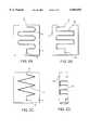
- FIGS. 2A-Cshow different possible meander conductor configurations provided on a flexible film carrier in accordance with the invention
- FIG. 2Dshows the flexible film carrier carrying the meander conductor formed into a cylindrical configuration, which could for example be used for substituting a helical conductor in various antenna applications;
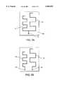
- FIGS. 3A-Bshow dual meander conductors tuned to different frequencies on common flexible film carriers providing dual band operability of an antenna means according to the invention, the dual meander conductors either being fed separately or via a common feed point;
- FIG. 4shows a combination of a meander conductor having a cylindrical configuration and an extendable and retractable whip antenna
- FIG. 5shows a combination of a meander conductor having a cylindrical configuration and an extendable and retractable whip antenna, wherein a flexible film carrier of the meander conductor is provided with matching means for matching the impedances of the meander conductor and the whip antenna, respectively, to an impedance on transmitter/receiver circuitry of a mobile telephone;
- FIG. 6shows another combination of a meander conductor having a cylindrical configuration and an extendable and retractable whip antenna, wherein the meander conductor and the whip antenna are connected in series when the whip antenna is in its extended position;
- FIG. 7shows yet another combination of a meander conductor and an extendable and retractable whip antenna, wherein a coaxial transmission line is connected to the meander conductor and the whip antenna, respectively;
- FIG. 8shows a combination of a meander conductor and an extendable and retractable whip antenna, wherein the whip antenna is in a retracted position
- FIG. 9shows a slightly different combination from that in FIG. 8, wherein the whip antenna is in a retracted position
- FIGS. 10A-Bshow still another combination of a meander conductor and an extendable and retractable whip antenna, wherein a top portion of the whip antenna carries the meander conductor and may or may not be conductively connected thereto.
- a meander radiating element 1is carried by a dielectric cylindrical carrier 2 and mounted extending outwards on a chassis 3 of a hand portable mobile telephone 4.
- the position of the meander element 1 on the chassis 3is selected such that radiation of the meander conductor 1 is transmitted and received effectively in different positions chosen by an operator during standby or during a telephone call.
- the meander elementis located at one side of a top portion of the chassis 3 projecting upwards.
- FIG. 1AAlso shown in FIG. 1A is an extendable and retractable whip antenna 5 shown in its extended position. There may or may not be a whip antenna combined with the meander element, depending on the antenna performance required in a specific case.
- FIG. 1Bshows the arrangement of FIG. 1A having the whip antenna in its retracted position.
- FIG. 2Ashows a first possible shape 6 of the meander radiating element being an etched conductor pattern on a dielectric flexible film carrier 7 in a flat configuration.
- the radiating elementextends from a feed point 8 at one edge of the carrier 7, which has an essentially rectangular shape, in an alternating curve including parallel sections and semi-circular turns to a free end 9 at an opposite edge of the carrier 7.
- the single meander radiating elementis to be formed from the flat configuration in to a configuration wherein the carrier 7 is tubular or, at least forms part of a cylinder, which will be shown further below.
- FIGS. 2B and 2Cshow, with corresponding reference numerals, second and third alternative shapes 10, 11, of the meander element, including rectangular and saw tooth shapes, respectively, extending on and to be formed together with the carrier 7 in a similar fashion to that of the meander element of FIG. 2A.
- FIG. 2Dshows a preferred cylindrical configuration into which the meander element 12 and the flexible film carrier 13 are shaped together.
- This configurationis compact and provides high durability. It can be used in most antenna applications where essentially the space occupied by a helical antenna is available, and, in particular, when a higher performance than that of a helical radiating element is required.
- the flexible film carriercould be exchanged for another dielectric carrier, preferably having a cylindrical shape with some suitable cross-section, on which a meander conductor may also be applied or developed by a high precision technique, for example etching.
- the configurationcan be said to have an imaginary central axis which the meander element 12 is arched about so that the angle relative the axis increases and decreases alternately.
- dual meander elements 14, 15 on a common carrier 16are shown, which are tuned to two different frequencies allowing operation of the antenna means in two overlapping or separated frequency bands. These elements are fed by a common feed point 17 to be coupled to circuitry of a hand portable mobile telephone, possibly via an impedance matching means (not shown). It would also be possible to arrange more than two meander elements together in order to achieve operability in more than two frequency bands or still wider band(s) than could be achieved by two elements.
- the flexible film carrier of the multi meander meansis preferably intended to be formed in to a cylindrical configuration as described above for a single meandering element.
- meander elementsprovide a great advantage over helical elements for operation within separated or wider frequency bands, since a degree of coupling between the individual elements is much less for meander elements than for helical elements assuming the same or comparable geometrical separations.
- FIG. 3Bshows an alternative to the feed arrangement of FIG. 3A.
- the individual elements 18, 19each have their own feed point 20, 19, respectively, to be coupled individually to circuitry of the telephone, possibly via an impedance matching means.
- a combinationincluding a cylindrically configured meander radiating element 22 carried by a cylindrical flexible film carrier 23, one point thereof being a feed point 24 and the other being a free end 25, an extendable conductive whip antenna 26 having a stopper 27 at a lower end which is adapted to contact the feed point 24 of the meander element 22 via a contact member 28 when the whip antenna 26 is extended, as is shown in FIG. 4, and having at the opposite end 29 an elongated dielectric portion 30 of the whip antenna terminated by a knob 31 for holding when sliding the whip antenna 26.
- the length of the elongated dielectric portion 30is essentially equal to the length of the cylindrically configured meander element 22, so that the whip antenna 26 does not co-extend with the meander element 22 in the retracted position (indicated in FIG. 8).
- the radiators 22, 26 of the antenna means in FIG. 4are preferable both of the same type, e.g., half-wave or quarter-wave type.
- the whip antennawhen a higher antenna performance is required, for example during a telephone call, generally, the whip antenna will be extended and contacted via the contact member to the feed point of the meander element, so that the meander element and the whip antenna will be connected in parallel to the circuitry of the telephone. In this configuration the whip antenna effects most of the antenna function. It will also be possible to provide an antenna of this type with more complicated switching means which would completely disconnect one of the elements when not needed.
- FIG. 5there is shown schematically a general way to arrange an impedance matching means 32 integrated on a dielectric carrier 33 of the inventive antenna device.
- the matching means 32is connected to a feed point 34 of a meander element 35 and includes reactive components 36, 37 (shown schematically) and connection terminals 38, 39 for signal and ground connectors (not shown) of the telephone.
- FIG. 6includes, preferably an essentially quarter-wave meander element 40 on a cylindrical dielectric carrier 41, preferably an essentially half-wave extendable and retractable whip antenna 42 having a dielectric elongated portion 43 mounted at an upper end 44.
- This arrangementdiffers further from that of FIG. 4 in that the whip antenna 42 is fed in its extended position, either conductively or capacitively, at its lower end 45 by a top portion of the meander element 40.
- FIG. 7includes, preferably an essentially quarter-wave meander element 46 on a cylindrical dielectric carrier 47, preferably an essentially quarter-wave extendable and retractable whip antenna 48 having a dielectric elongated portion 49 mounted at an upper end 50.
- This arrangementdiffers further from that of FIG. 4 in that the inner conductor 51 of a (coaxial) transmission line 51 feeds the whip antenna 48 in its extended position, either conductively or capacitively, at its lower end 53, and a top end 54 of the meander element 46 is fed by the shield 55 of the transmission line 52, while a lower end 56 of the meander element 46 is an open end.
- the whip antenna 57will be retracted as shown in FIG. 8. Generally, the whip antenna 57 then provides little or none of the antenna function, while the meander element(s) 58 transmits and receives radiation power to and from the telephone.
- the dielectric portion 59extends along the full axial length of the meander element 58, so that the whip is decoupled in the retracted position.
- the whip antenna 60may co-extend at least partially with the cylindrically configured meander element 61 even in the retracted position of the whip antenna 60.
- the elongated dielectric portion 62co-extends only partially with the meander element 61 when the whip antenna is retracted.
- FIGS. 10A and 10Bshow in retracted and extended positions, respectively, a whip antenna 63 carrying at is top end 64 a meander element 65.
- a conductive sleeve 66constitutes a connection point to circuitry (or a matching means) of a telephone. Either, there is a conductive connection between the whip and meander elements, so that they together contact the sleeve 66 at the portion 64 when retracted and at a portion 67 when extended, or there is no conductive contact, so that the meander element 65 alone contacts the sleeve 66 in the retracted position and the antenna whip 63 alone contacts the sleeve 66 in the extended position.
- Various multi-band antenna meansmay be constructed according to the principles described above with reference to FIGS. 4-10 if more than one meander element are included.
Landscapes
- Engineering & Computer Science (AREA)
- Computer Networks & Wireless Communication (AREA)
- Support Of Aerials (AREA)
- Details Of Aerials (AREA)
- Variable-Direction Aerials And Aerial Arrays (AREA)
Abstract
Description
Claims (35)
Priority Applications (1)
| Application Number | Priority Date | Filing Date | Title |
|---|---|---|---|
| US09/387,831US6351241B1 (en) | 1996-06-15 | 1999-09-01 | Meander antenna device |
Applications Claiming Priority (2)
| Application Number | Priority Date | Filing Date | Title |
|---|---|---|---|
| SE9602387ASE509638C2 (en) | 1996-06-15 | 1996-06-15 | Meander antenna device |
| SE9602387 | 1996-06-15 |
Related Child Applications (1)
| Application Number | Title | Priority Date | Filing Date |
|---|---|---|---|
| US09/387,831ContinuationUS6351241B1 (en) | 1996-06-15 | 1999-09-01 | Meander antenna device |
Publications (1)
| Publication Number | Publication Date |
|---|---|
| US6069592Atrue US6069592A (en) | 2000-05-30 |
Family
ID=20403038
Family Applications (2)
| Application Number | Title | Priority Date | Filing Date |
|---|---|---|---|
| US08/872,921Expired - LifetimeUS6069592A (en) | 1996-06-15 | 1997-06-11 | Meander antenna device |
| US09/387,831Expired - LifetimeUS6351241B1 (en) | 1996-06-15 | 1999-09-01 | Meander antenna device |
Family Applications After (1)
| Application Number | Title | Priority Date | Filing Date |
|---|---|---|---|
| US09/387,831Expired - LifetimeUS6351241B1 (en) | 1996-06-15 | 1999-09-01 | Meander antenna device |
Country Status (8)
| Country | Link |
|---|---|
| US (2) | US6069592A (en) |
| EP (1) | EP0904611B1 (en) |
| JP (1) | JP2000516056A (en) |
| CN (1) | CN1108641C (en) |
| AU (1) | AU3280897A (en) |
| DE (1) | DE69724253T2 (en) |
| SE (1) | SE509638C2 (en) |
| WO (1) | WO1997049141A1 (en) |
Cited By (48)
| Publication number | Priority date | Publication date | Assignee | Title |
|---|---|---|---|---|
| US6163307A (en)* | 1998-12-01 | 2000-12-19 | Korea Electronics Technology Institute | Multilayered helical antenna for mobile telecommunication units |
| US6204826B1 (en)* | 1999-07-22 | 2001-03-20 | Ericsson Inc. | Flat dual frequency band antennas for wireless communicators |
| US6232925B1 (en)* | 1994-01-28 | 2001-05-15 | Smk Corporation | Antenna device |
| US6236373B1 (en)* | 1999-09-15 | 2001-05-22 | Humentech 21 Company | Vehicle sun visor with radio antenna |
| US6249262B1 (en)* | 1999-11-03 | 2001-06-19 | Motorola, Inc. | Switchable antenna for radio communication devices |
| US6329962B2 (en) | 1998-08-04 | 2001-12-11 | Telefonaktiebolaget Lm Ericsson (Publ) | Multiple band, multiple branch antenna for mobile phone |
| US6351241B1 (en)* | 1996-06-15 | 2002-02-26 | Allgon Ab | Meander antenna device |
| EP1184935A1 (en)* | 2000-09-04 | 2002-03-06 | Hong-Doo Yang | Meander antenna for mobile telephone |
| US6380900B1 (en)* | 2000-03-21 | 2002-04-30 | Sony Corporation | Antenna apparatus and wireless communication apparatus |
| US6388625B1 (en)* | 1998-03-19 | 2002-05-14 | Matsushita Electric Industrial Co., Ltd. | Antenna device and mobile communication unit |
| US6424302B1 (en)* | 2000-12-20 | 2002-07-23 | Senton Enterprise Co., Ltd. | Simplified dual-frequency antenna for mobile phone |
| US6442400B1 (en)* | 1997-11-06 | 2002-08-27 | Telefonaktiebolaget L M Ericsson (Publ) | Portable electronic communication device with dual-band antenna system |
| US6445347B1 (en)* | 1999-04-06 | 2002-09-03 | Mitsubishi Denki Kabushiki Kaisha | Portable radio devices and manufacturing method of portable radio devices body |
| US20020135533A1 (en)* | 2001-03-24 | 2002-09-26 | Samsung Electronics Co., Ltd. | Retractable/extendable antenna unit having a conductive tube in a portable radiophone |
| US6459413B1 (en)* | 2001-01-10 | 2002-10-01 | Industrial Technology Research Institute | Multi-frequency band antenna |
| US6483470B1 (en) | 1999-09-08 | 2002-11-19 | Qwest Communications International, Inc. | Power supply for a light pole mounted wireless antenna |
| US6563476B1 (en)* | 1998-09-16 | 2003-05-13 | Siemens Ag | Antenna which can be operated in a number of frequency bands |
| US6593900B1 (en) | 2002-03-04 | 2003-07-15 | West Virginia University | Flexible printed circuit board antenna |
| US20030189523A1 (en)* | 2002-04-09 | 2003-10-09 | Filtronic Lk Oy | Antenna with variable directional pattern |
| US6642893B1 (en) | 2002-05-09 | 2003-11-04 | Centurion Wireless Technologies, Inc. | Multi-band antenna system including a retractable antenna and a meander antenna |
| US20040038644A1 (en)* | 2002-08-22 | 2004-02-26 | Eagle Broadband, Inc. | Repeater for a satellite phone |
| KR20040037918A (en)* | 2002-10-31 | 2004-05-08 | 주식회사 케이티 | Single feed dual band antenna |
| US6781549B1 (en) | 1999-10-12 | 2004-08-24 | Galtronics Ltd. | Portable antenna |
| US6788259B2 (en)* | 2001-01-04 | 2004-09-07 | Kabushiki Kaisha Toshiba | Antenna structure and mobile terminal having antenna structure |
| US20040189536A1 (en)* | 2001-06-27 | 2004-09-30 | Byung-Hoon Ryou | Antenna for portable wireless communication apparatuses |
| US20040213218A1 (en)* | 1999-09-08 | 2004-10-28 | Qwest Communications International Inc. | System and method for dynamic distributed communication |
| US6831902B1 (en) | 1999-09-08 | 2004-12-14 | Qwest Communications International, Inc. | Routing information packets in a distributed network |
| US20050001783A1 (en)* | 2002-10-17 | 2005-01-06 | Daniel Wang | Broad band antenna |
| US20050007282A1 (en)* | 2003-05-14 | 2005-01-13 | Matti Martiskainen | Antenna |
| US6885845B1 (en)* | 1993-04-05 | 2005-04-26 | Ambit Corp. | Personal communication device connectivity arrangement |
| US20050093765A1 (en)* | 2003-10-30 | 2005-05-05 | Nagel Jon L. | High performance antenna |
| US20050110688A1 (en)* | 1999-09-20 | 2005-05-26 | Baliarda Carles P. | Multilevel antennae |
| US20050184924A1 (en)* | 2004-02-20 | 2005-08-25 | Larry Fossett | Systems and methods that utilize an active stub/parasitic whip antenna to facilitate mobile communication |
| US20050195112A1 (en)* | 2000-01-19 | 2005-09-08 | Baliarda Carles P. | Space-filling miniature antennas |
| EP1153888A4 (en)* | 1998-11-27 | 2006-03-29 | Rohm Co Ltd | METHOD FOR PRODUCING A SOLID INORGANIC COMPOSITION AND METHOD FOR PRODUCING A SEMICONDUCTOR ELEMENT |
| EP1653561A1 (en)* | 2004-10-29 | 2006-05-03 | Samsung Electronics Co., Ltd. | Embedded antenna of mobile terminal |
| US20060214850A1 (en)* | 2005-03-24 | 2006-09-28 | Tdk Corporation | Stacked multi-resonator antenna |
| US20060290577A1 (en)* | 2005-06-09 | 2006-12-28 | Mete Ozkar | Retractable stubby antenna |
| US20070205948A1 (en)* | 2004-03-31 | 2007-09-06 | Ace Technology | Multiband Antenna Using Whip Having Independent Power Feeding In Wireless Telecommunication Terminal |
| US20080042918A1 (en)* | 2004-02-20 | 2008-02-21 | Lg Telecom, Ltd. | Mobile Terminal Equipment and Antenna Thereof |
| US7388846B1 (en) | 1999-09-08 | 2008-06-17 | Qwest Communications International Inc. | Cellularized packetized voice and data |
| US20080198075A1 (en)* | 2007-02-20 | 2008-08-21 | Mitsumi Electric Co. Ltd. | Broadband antenna unit comprising a folded plate-shaped monopole antenna portion and an extending portion |
| US7561895B1 (en) | 1999-09-08 | 2009-07-14 | Qwest Communications International, Inc. | Reverse sectorization wireless communication |
| US20100141847A1 (en)* | 2008-12-05 | 2010-06-10 | Subramanian Jayaram | Mobile television device with break-resistant integrated telescoping antenna |
| US7750850B2 (en)* | 2007-01-12 | 2010-07-06 | Hon Hai Precision Industry Co., Ltd. | Printed antenna |
| US8005077B1 (en) | 1999-09-08 | 2011-08-23 | Qwest Communications International Inc. | Distributively routed VDSL and high-speed information packets |
| US8738103B2 (en) | 2006-07-18 | 2014-05-27 | Fractus, S.A. | Multiple-body-configuration multimedia and smartphone multifunction wireless devices |
| US9806396B2 (en) | 2012-09-28 | 2017-10-31 | Huawei Device Co., Ltd. | Antenna, combination antenna, and mobile terminal |
Families Citing this family (58)
| Publication number | Priority date | Publication date | Assignee | Title |
|---|---|---|---|---|
| EP1345283A1 (en)* | 1996-06-20 | 2003-09-17 | Kabushiki Kaisha Yokowo (also trading as Yokowo Co., Ltd.) | Antenna |
| FI110394B (en)* | 1996-08-06 | 2003-01-15 | Filtronic Lk Oy | combination Antenna |
| FI113214B (en)* | 1997-01-24 | 2004-03-15 | Filtronic Lk Oy | Simple dual frequency antenna |
| SE511501C2 (en) | 1997-07-09 | 1999-10-11 | Allgon Ab | Compact antenna device |
| AU9657998A (en)* | 1997-10-28 | 1999-05-17 | Telefonaktiebolaget Lm Ericsson (Publ) | Multiple band, multiple branch antenna for mobile phone |
| JP3041520B2 (en) | 1998-01-19 | 2000-05-15 | 株式会社トーキン | antenna |
| US6040803A (en)* | 1998-02-19 | 2000-03-21 | Ericsson Inc. | Dual band diversity antenna having parasitic radiating element |
| US6611691B1 (en)* | 1998-12-24 | 2003-08-26 | Motorola, Inc. | Antenna adapted to operate in a plurality of frequency bands |
| SE9900412D0 (en)* | 1998-04-01 | 1999-02-08 | Allgon Ab | Antenna means, a method for its manufacturing and a hand-held radio communication device |
| SE513055C2 (en)* | 1998-04-24 | 2000-06-26 | Intenna Technology Ab | The multiband antenna device |
| EP0954054A1 (en)* | 1998-04-30 | 1999-11-03 | Kabushiki Kaisha Yokowo | Folded antenna |
| US5977928A (en)* | 1998-05-29 | 1999-11-02 | Telefonaktiebolaget Lm Ericsson | High efficiency, multi-band antenna for a radio communication device |
| US5986609A (en)* | 1998-06-03 | 1999-11-16 | Ericsson Inc. | Multiple frequency band antenna |
| US6166694A (en)* | 1998-07-09 | 2000-12-26 | Telefonaktiebolaget Lm Ericsson (Publ) | Printed twin spiral dual band antenna |
| US6353443B1 (en)* | 1998-07-09 | 2002-03-05 | Telefonaktiebolaget Lm Ericsson (Publ) | Miniature printed spiral antenna for mobile terminals |
| US6343208B1 (en) | 1998-12-16 | 2002-01-29 | Telefonaktiebolaget Lm Ericsson (Publ) | Printed multi-band patch antenna |
| JP2000269714A (en)* | 1999-03-12 | 2000-09-29 | Nec Corp | Antenna device for portable radio equipment |
| US6859182B2 (en) | 1999-03-18 | 2005-02-22 | Dx Antenna Company, Limited | Antenna system |
| US6255999B1 (en) | 1999-04-28 | 2001-07-03 | The Whitaker Corporation | Antenna element having a zig zag pattern |
| AU4674800A (en)* | 1999-04-28 | 2000-11-10 | Whitaker Corporation, The | Antenna element having a zig zag pattern |
| FI991218L (en) | 1999-05-28 | 2000-11-29 | Nokia Mobile Phones Ltd | Antenna structure of an electronic device expansion card |
| JP3347093B2 (en)* | 1999-06-10 | 2002-11-20 | 埼玉日本電気株式会社 | Portable wireless device and terminal matching switching method |
| FI112986B (en) | 1999-06-14 | 2004-02-13 | Filtronic Lk Oy | Antenna Design |
| US6198442B1 (en)* | 1999-07-22 | 2001-03-06 | Ericsson Inc. | Multiple frequency band branch antennas for wireless communicators |
| SE9902877L (en)* | 1999-08-11 | 2001-02-12 | Allgon Ab | Antenna unit for two bands |
| SE514515C2 (en)* | 1999-08-11 | 2001-03-05 | Allgon Ab | Compact multi-band antenna |
| WO2001020716A1 (en)* | 1999-09-17 | 2001-03-22 | Avantego Ab | Antenna arrangement and a method for reducing size of a whip element in an antenna arrangement |
| SE0001098D0 (en)* | 1999-11-01 | 2000-03-28 | Allgon Ab | Antenna device, a method for its manufacture and a contact clip for such antenna device |
| US6417808B1 (en) | 2000-03-07 | 2002-07-09 | Nec Corporation | Transceiver including antenna apparatus which is compactly accommodated in body of transceiver |
| DE10049410A1 (en)* | 2000-10-05 | 2002-04-11 | Siemens Ag | Mobile phone with multi-band antenna |
| GB0030741D0 (en)* | 2000-12-16 | 2001-01-31 | Koninkl Philips Electronics Nv | Antenna arrangement |
| EP1346439B1 (en)* | 2000-12-22 | 2007-11-07 | Antenova Limited | Antenna device |
| US6674405B2 (en) | 2001-02-15 | 2004-01-06 | Benq Corporation | Dual-band meandering-line antenna |
| US6466170B2 (en)* | 2001-03-28 | 2002-10-15 | Motorola, Inc. | Internal multi-band antennas for mobile communications |
| EP1267439B1 (en)* | 2001-06-15 | 2005-07-27 | Hewlett-Packard Company | Multiple frequency bands antenna using two concentric interleaved antennas, the external one being a meander line antenna |
| US6995710B2 (en)* | 2001-10-09 | 2006-02-07 | Ngk Spark Plug Co., Ltd. | Dielectric antenna for high frequency wireless communication apparatus |
| JP2003347827A (en)* | 2002-05-28 | 2003-12-05 | Ngk Spark Plug Co Ltd | Antenna and radio frequency module using the same |
| JP3726070B2 (en)* | 2002-05-28 | 2005-12-14 | Necアクセステクニカ株式会社 | Portable wireless terminal |
| JP2004015623A (en)* | 2002-06-10 | 2004-01-15 | Nippon Antenna Co Ltd | Multi-resonant antenna and portable radio antenna |
| EP1372213A1 (en)* | 2002-06-11 | 2003-12-17 | Industrial Technology Research Institute | Multi-frequency band antenna |
| JP2004186931A (en)* | 2002-12-03 | 2004-07-02 | Ngk Spark Plug Co Ltd | Antenna capable of coping with a plurality of frequency bands |
| CN100524945C (en)* | 2003-01-14 | 2009-08-05 | 摩托罗拉公司 | Radio communication device and antenna capable of working at multiband |
| US7173567B2 (en)* | 2003-01-16 | 2007-02-06 | Matsushita Electric Industrial Co., Ltd. | Antenna |
| JP2005176302A (en) | 2003-09-26 | 2005-06-30 | Nec Access Technica Ltd | Antenna assembly of portable terminal, and wireless installation capable of receiving broadcast wave |
| WO2005120164A2 (en)* | 2004-06-10 | 2005-12-22 | Galtronics Ltd. | Three dimensional antennas formed using wet conductive materials and methods for production thereof |
| US7486241B2 (en)* | 2004-12-16 | 2009-02-03 | Research In Motion Limited | Low profile full wavelength meandering antenna |
| JP4308786B2 (en)* | 2005-02-24 | 2009-08-05 | パナソニック株式会社 | Portable radio |
| KR100766784B1 (en)* | 2006-03-31 | 2007-10-12 | 주식회사 이엠따블유안테나 | antenna |
| GB2437115B (en) | 2006-04-13 | 2008-10-29 | Motorola Inc | Antenna arrangement and an RF communication terminal incorporating the arrangement |
| KR100793303B1 (en) | 2006-07-28 | 2008-01-10 | 삼성전자주식회사 | Dual band antenna device of mobile terminal |
| US7847736B2 (en)* | 2006-08-24 | 2010-12-07 | Cobham Defense Electronic Systems | Multi section meander antenna |
| US8816925B2 (en) | 2009-05-06 | 2014-08-26 | Bae Systems Information And Electronic Systems Integration Inc. | Multiband whip antenna |
| CN101989681B (en)* | 2009-08-06 | 2016-09-28 | 立积电子股份有限公司 | Multi-band microstrip meander antenna |
| JP2011176560A (en)* | 2010-02-24 | 2011-09-08 | Fujitsu Ltd | Antenna apparatus, and radio terminal apparatus |
| EP2551957A4 (en)* | 2010-03-24 | 2014-04-02 | Hytera Comm Corp Ltd | ANTENNA WHIP BIBANDE |
| JP2013042230A (en)* | 2011-08-11 | 2013-02-28 | Lixil Corp | Housing information communication system |
| KR101888986B1 (en) | 2012-03-21 | 2018-08-16 | 삼성전자주식회사 | Antenna device for wireless communication terminal |
| US10135139B2 (en)* | 2014-07-10 | 2018-11-20 | Motorola Solutions, Inc. | Multiband antenna system |
Citations (5)
| Publication number | Priority date | Publication date | Assignee | Title |
|---|---|---|---|---|
| US4121218A (en)* | 1977-08-03 | 1978-10-17 | Motorola, Inc. | Adjustable antenna arrangement for a portable radio |
| EP0511577A2 (en)* | 1991-04-30 | 1992-11-04 | Siemens Aktiengesellschaft | Compact, in particular portable radio transceiver with retractable or collapsible antenna |
| US5374937A (en)* | 1991-07-08 | 1994-12-20 | Nippon Telegraph And Telephone Corporation | Retractable antenna system |
| US5559524A (en)* | 1991-03-18 | 1996-09-24 | Hitachi, Ltd. | Antenna system including a plurality of meander conductors for a portable radio apparatus |
| WO1997034377A1 (en)* | 1996-03-15 | 1997-09-18 | Ericsson Inc. | Dual antenna arrangement for portable transceiver |
Family Cites Families (26)
| Publication number | Priority date | Publication date | Assignee | Title |
|---|---|---|---|---|
| US4335936A (en)* | 1977-10-14 | 1982-06-22 | Sharp Kabushiki Kaisha | Matrix electrode structure in a multi-layer matrix type liquid crystal display |
| JPS55146489A (en)* | 1979-04-20 | 1980-11-14 | Suwa Seikosha Kk | Liquid crystal matrix display unit |
| JPS5660483A (en)* | 1979-10-24 | 1981-05-25 | Hitachi Ltd | Liquid crystal display unit |
| US4313119A (en) | 1980-04-18 | 1982-01-26 | Motorola, Inc. | Dual mode transceiver antenna |
| JPS56150785A (en)* | 1980-04-23 | 1981-11-21 | Hitachi Ltd | Liquid crystal display unit |
| DE3129045A1 (en)* | 1981-04-08 | 1982-10-28 | C. Plath Gmbh Nautisch-Elektronische Technik, 2000 Hamburg | Direction-finding antenna system |
| US4571595A (en) | 1983-12-05 | 1986-02-18 | Motorola, Inc. | Dual band transceiver antenna |
| US4859037A (en)* | 1986-02-18 | 1989-08-22 | Seiko Epson Corporation | Liquid crystal electrically-controlled birefringence display devices with improved contrast |
| KR900009111B1 (en) | 1986-11-07 | 1990-12-22 | 야기 안테나 가부시기가이샤 | Antenna devices of film |
| US4860020A (en) | 1987-04-30 | 1989-08-22 | The Aerospace Corporation | Compact, wideband antenna system |
| EP0352101B1 (en)* | 1988-07-19 | 1994-09-14 | Sharp Kabushiki Kaisha | A double-layered type liquid-crystal display device |
| US4952036A (en)* | 1989-06-07 | 1990-08-28 | In Focus Systems, Inc. | High resolution LCD display system |
| EP0509053B1 (en)* | 1989-12-31 | 1995-08-30 | A.D.P. ADAPTIVE VISUAL PERCEPTION Ltd. | Self-masking transparency viewing apparatus |
| JP3185233B2 (en) | 1991-03-18 | 2001-07-09 | 株式会社日立製作所 | Small antenna for portable radio |
| WO1993001564A1 (en)* | 1991-07-11 | 1993-01-21 | Dan Inbar | Position sensing display device |
| JPH05347507A (en) | 1992-06-12 | 1993-12-27 | Junkosha Co Ltd | Antenna |
| SE512062C2 (en)* | 1993-07-14 | 2000-01-17 | Ericsson Ge Mobile Communicat | Method and apparatus for improving the efficiency and bandwidth of an antenna on a portable equipment |
| DE69409447T2 (en) | 1993-07-30 | 1998-11-05 | Matsushita Electric Ind Co Ltd | Antenna for mobile radio |
| GB2280789B (en)* | 1993-08-06 | 1997-05-07 | Antenna Products Ltd | Multiple turn antenna element |
| JPH0846417A (en) | 1994-07-26 | 1996-02-16 | Sansei Denki Kk | Method for connecting ultrashort wave wide band whip antenna and connection structure for the same |
| US5561437A (en) | 1994-09-15 | 1996-10-01 | Motorola, Inc. | Two position fold-over dipole antenna |
| JPH08102617A (en) | 1994-09-30 | 1996-04-16 | Matsushita Electric Ind Co Ltd | Antenna device |
| CN1150660C (en) | 1995-06-02 | 2004-05-19 | 艾利森公司 | Multiple band printed monopole antenna |
| BR9608629A (en) | 1995-06-02 | 1999-05-04 | Ericsson Ge Mobile Inc | Antenna |
| SE509638C2 (en)* | 1996-06-15 | 1999-02-15 | Allgon Ab | Meander antenna device |
| FI110394B (en)* | 1996-08-06 | 2003-01-15 | Filtronic Lk Oy | combination Antenna |
- 1996
- 1996-06-15SESE9602387Apatent/SE509638C2/ennot_activeIP Right Cessation
- 1997
- 1997-06-11USUS08/872,921patent/US6069592A/ennot_activeExpired - Lifetime
- 1997-06-13WOPCT/SE1997/001046patent/WO1997049141A1/ennot_activeApplication Discontinuation
- 1997-06-13EPEP97928588Apatent/EP0904611B1/ennot_activeRevoked
- 1997-06-13JPJP10502789Apatent/JP2000516056A/enactivePending
- 1997-06-13CNCN97195542Apatent/CN1108641C/ennot_activeExpired - Fee Related
- 1997-06-13AUAU32808/97Apatent/AU3280897A/ennot_activeAbandoned
- 1997-06-13DEDE69724253Tpatent/DE69724253T2/ennot_activeExpired - Fee Related
- 1999
- 1999-09-01USUS09/387,831patent/US6351241B1/ennot_activeExpired - Lifetime
Patent Citations (5)
| Publication number | Priority date | Publication date | Assignee | Title |
|---|---|---|---|---|
| US4121218A (en)* | 1977-08-03 | 1978-10-17 | Motorola, Inc. | Adjustable antenna arrangement for a portable radio |
| US5559524A (en)* | 1991-03-18 | 1996-09-24 | Hitachi, Ltd. | Antenna system including a plurality of meander conductors for a portable radio apparatus |
| EP0511577A2 (en)* | 1991-04-30 | 1992-11-04 | Siemens Aktiengesellschaft | Compact, in particular portable radio transceiver with retractable or collapsible antenna |
| US5374937A (en)* | 1991-07-08 | 1994-12-20 | Nippon Telegraph And Telephone Corporation | Retractable antenna system |
| WO1997034377A1 (en)* | 1996-03-15 | 1997-09-18 | Ericsson Inc. | Dual antenna arrangement for portable transceiver |
Non-Patent Citations (6)
| Title |
|---|
| Ali et al, IEEE 1995, "A Wideband Dual Meander Sleeve Antenna", pp. 1124-1127. |
| Ali et al, IEEE 1995, A Wideband Dual Meander Sleeve Antenna , pp. 1124 1127.* |
| Ali et al, IEEE 1995, Short Sinusoidal Antennas for Wireless Communications, pp. 542 545.* |
| Ali et al, IEEE 1995, Short Sinusoidal Antennas for Wireless Communications, pp. 542-545. |
| Derwent Accession No. 96 249236, Jun. 1996, Antenna device for e.g. cordless telephone . . . , JP 08102617, 3 pgs.* |
| Derwent Accession No. 96-249236, Jun. 1996, "Antenna device for e.g. cordless telephone . . .", JP-08102617, 3 pgs. |
Cited By (113)
| Publication number | Priority date | Publication date | Assignee | Title |
|---|---|---|---|---|
| US6885845B1 (en)* | 1993-04-05 | 2005-04-26 | Ambit Corp. | Personal communication device connectivity arrangement |
| US6232925B1 (en)* | 1994-01-28 | 2001-05-15 | Smk Corporation | Antenna device |
| US6351241B1 (en)* | 1996-06-15 | 2002-02-26 | Allgon Ab | Meander antenna device |
| US6442400B1 (en)* | 1997-11-06 | 2002-08-27 | Telefonaktiebolaget L M Ericsson (Publ) | Portable electronic communication device with dual-band antenna system |
| US6388625B1 (en)* | 1998-03-19 | 2002-05-14 | Matsushita Electric Industrial Co., Ltd. | Antenna device and mobile communication unit |
| US6329962B2 (en) | 1998-08-04 | 2001-12-11 | Telefonaktiebolaget Lm Ericsson (Publ) | Multiple band, multiple branch antenna for mobile phone |
| US6888514B2 (en) | 1998-09-16 | 2005-05-03 | Siemens Aktiengesellschaft | Antenna which can be operated in a number of frequency bands |
| US20030117340A1 (en)* | 1998-09-16 | 2003-06-26 | Pan Sheng-Gen | Antenna which can be operated in a number of frequency bands |
| US6563476B1 (en)* | 1998-09-16 | 2003-05-13 | Siemens Ag | Antenna which can be operated in a number of frequency bands |
| EP1153888A4 (en)* | 1998-11-27 | 2006-03-29 | Rohm Co Ltd | METHOD FOR PRODUCING A SOLID INORGANIC COMPOSITION AND METHOD FOR PRODUCING A SEMICONDUCTOR ELEMENT |
| US6163307A (en)* | 1998-12-01 | 2000-12-19 | Korea Electronics Technology Institute | Multilayered helical antenna for mobile telecommunication units |
| US6445347B1 (en)* | 1999-04-06 | 2002-09-03 | Mitsubishi Denki Kabushiki Kaisha | Portable radio devices and manufacturing method of portable radio devices body |
| US6204826B1 (en)* | 1999-07-22 | 2001-03-20 | Ericsson Inc. | Flat dual frequency band antennas for wireless communicators |
| US7561895B1 (en) | 1999-09-08 | 2009-07-14 | Qwest Communications International, Inc. | Reverse sectorization wireless communication |
| US7561540B2 (en) | 1999-09-08 | 2009-07-14 | Qwest Communications International, Inc. | System and method for dynamic distributed communication |
| US6483470B1 (en) | 1999-09-08 | 2002-11-19 | Qwest Communications International, Inc. | Power supply for a light pole mounted wireless antenna |
| US8005077B1 (en) | 1999-09-08 | 2011-08-23 | Qwest Communications International Inc. | Distributively routed VDSL and high-speed information packets |
| US8098605B2 (en) | 1999-09-08 | 2012-01-17 | Qwest Communications International Inc. | System and method for dynamic distributed communication |
| US20040213218A1 (en)* | 1999-09-08 | 2004-10-28 | Qwest Communications International Inc. | System and method for dynamic distributed communication |
| US7388846B1 (en) | 1999-09-08 | 2008-06-17 | Qwest Communications International Inc. | Cellularized packetized voice and data |
| US8457027B2 (en) | 1999-09-08 | 2013-06-04 | Qwest Communications International Inc. | System and method for dynamic distributed communication |
| US6987769B1 (en) | 1999-09-08 | 2006-01-17 | Qwest Communications International Inc. | System and method for dynamic distributed communication |
| US7688801B2 (en) | 1999-09-08 | 2010-03-30 | Qwest Communications International Inc. | Routing information packets in a distributed network |
| US20050036460A1 (en)* | 1999-09-08 | 2005-02-17 | Qwest Communications International Inc. | Routing information packets in a distributed network |
| US6831902B1 (en) | 1999-09-08 | 2004-12-14 | Qwest Communications International, Inc. | Routing information packets in a distributed network |
| US6236373B1 (en)* | 1999-09-15 | 2001-05-22 | Humentech 21 Company | Vehicle sun visor with radio antenna |
| US8154462B2 (en) | 1999-09-20 | 2012-04-10 | Fractus, S.A. | Multilevel antennae |
| US7394432B2 (en) | 1999-09-20 | 2008-07-01 | Fractus, S.A. | Multilevel antenna |
| US8009111B2 (en) | 1999-09-20 | 2011-08-30 | Fractus, S.A. | Multilevel antennae |
| US8330659B2 (en) | 1999-09-20 | 2012-12-11 | Fractus, S.A. | Multilevel antennae |
| US9761934B2 (en) | 1999-09-20 | 2017-09-12 | Fractus, S.A. | Multilevel antennae |
| US10056682B2 (en) | 1999-09-20 | 2018-08-21 | Fractus, S.A. | Multilevel antennae |
| US20090167625A1 (en)* | 1999-09-20 | 2009-07-02 | Fractus, S.A. | Multilevel antennae |
| US7528782B2 (en) | 1999-09-20 | 2009-05-05 | Fractus, S.A. | Multilevel antennae |
| US7505007B2 (en) | 1999-09-20 | 2009-03-17 | Fractus, S.A. | Multi-level antennae |
| US20050110688A1 (en)* | 1999-09-20 | 2005-05-26 | Baliarda Carles P. | Multilevel antennae |
| US7397431B2 (en) | 1999-09-20 | 2008-07-08 | Fractus, S.A. | Multilevel antennae |
| US9362617B2 (en) | 1999-09-20 | 2016-06-07 | Fractus, S.A. | Multilevel antennae |
| US8941541B2 (en) | 1999-09-20 | 2015-01-27 | Fractus, S.A. | Multilevel antennae |
| US8976069B2 (en) | 1999-09-20 | 2015-03-10 | Fractus, S.A. | Multilevel antennae |
| US9000985B2 (en) | 1999-09-20 | 2015-04-07 | Fractus, S.A. | Multilevel antennae |
| US9054421B2 (en) | 1999-09-20 | 2015-06-09 | Fractus, S.A. | Multilevel antennae |
| US20050259009A1 (en)* | 1999-09-20 | 2005-11-24 | Carles Puente Baliarda | Multilevel antennae |
| US9240632B2 (en) | 1999-09-20 | 2016-01-19 | Fractus, S.A. | Multilevel antennae |
| US8154463B2 (en) | 1999-09-20 | 2012-04-10 | Fractus, S.A. | Multilevel antennae |
| US20060290573A1 (en)* | 1999-09-20 | 2006-12-28 | Carles Puente Baliarda | Multilevel antennae |
| US7015868B2 (en) | 1999-09-20 | 2006-03-21 | Fractus, S.A. | Multilevel Antennae |
| US7123208B2 (en) | 1999-09-20 | 2006-10-17 | Fractus, S.A. | Multilevel antennae |
| US6781549B1 (en) | 1999-10-12 | 2004-08-24 | Galtronics Ltd. | Portable antenna |
| US6249262B1 (en)* | 1999-11-03 | 2001-06-19 | Motorola, Inc. | Switchable antenna for radio communication devices |
| US7164386B2 (en) | 2000-01-19 | 2007-01-16 | Fractus, S.A. | Space-filling miniature antennas |
| US8212726B2 (en) | 2000-01-19 | 2012-07-03 | Fractus, Sa | Space-filling miniature antennas |
| US7148850B2 (en) | 2000-01-19 | 2006-12-12 | Fractus, S.A. | Space-filling miniature antennas |
| US9331382B2 (en) | 2000-01-19 | 2016-05-03 | Fractus, S.A. | Space-filling miniature antennas |
| US8610627B2 (en) | 2000-01-19 | 2013-12-17 | Fractus, S.A. | Space-filling miniature antennas |
| US8207893B2 (en) | 2000-01-19 | 2012-06-26 | Fractus, S.A. | Space-filling miniature antennas |
| US7554490B2 (en) | 2000-01-19 | 2009-06-30 | Fractus, S.A. | Space-filling miniature antennas |
| US7202822B2 (en) | 2000-01-19 | 2007-04-10 | Fractus, S.A. | Space-filling miniature antennas |
| US20050264453A1 (en)* | 2000-01-19 | 2005-12-01 | Baliarda Carles P | Space-filling miniature antennas |
| US8558741B2 (en) | 2000-01-19 | 2013-10-15 | Fractus, S.A. | Space-filling miniature antennas |
| US8471772B2 (en) | 2000-01-19 | 2013-06-25 | Fractus, S.A. | Space-filling miniature antennas |
| US20050231427A1 (en)* | 2000-01-19 | 2005-10-20 | Carles Puente Baliarda | Space-filling miniature antennas |
| US20050195112A1 (en)* | 2000-01-19 | 2005-09-08 | Baliarda Carles P. | Space-filling miniature antennas |
| US10355346B2 (en) | 2000-01-19 | 2019-07-16 | Fractus, S.A. | Space-filling miniature antennas |
| US6380900B1 (en)* | 2000-03-21 | 2002-04-30 | Sony Corporation | Antenna apparatus and wireless communication apparatus |
| EP1184935A1 (en)* | 2000-09-04 | 2002-03-06 | Hong-Doo Yang | Meander antenna for mobile telephone |
| US6424302B1 (en)* | 2000-12-20 | 2002-07-23 | Senton Enterprise Co., Ltd. | Simplified dual-frequency antenna for mobile phone |
| US6788259B2 (en)* | 2001-01-04 | 2004-09-07 | Kabushiki Kaisha Toshiba | Antenna structure and mobile terminal having antenna structure |
| US6459413B1 (en)* | 2001-01-10 | 2002-10-01 | Industrial Technology Research Institute | Multi-frequency band antenna |
| US6756943B2 (en)* | 2001-03-24 | 2004-06-29 | Samsung Electronics Co., Ltd. | Retractable/extendable antenna unit having a conductive tube in a portable radiophone |
| US20020135533A1 (en)* | 2001-03-24 | 2002-09-26 | Samsung Electronics Co., Ltd. | Retractable/extendable antenna unit having a conductive tube in a portable radiophone |
| US6911943B2 (en)* | 2001-06-27 | 2005-06-28 | E.M.W. Antenna Co., Ltd. | Antenna for portable wireless communication apparatuses |
| US20040189536A1 (en)* | 2001-06-27 | 2004-09-30 | Byung-Hoon Ryou | Antenna for portable wireless communication apparatuses |
| US6593900B1 (en) | 2002-03-04 | 2003-07-15 | West Virginia University | Flexible printed circuit board antenna |
| US6967618B2 (en)* | 2002-04-09 | 2005-11-22 | Filtronic Lk Oy | Antenna with variable directional pattern |
| US20030189523A1 (en)* | 2002-04-09 | 2003-10-09 | Filtronic Lk Oy | Antenna with variable directional pattern |
| US6642893B1 (en) | 2002-05-09 | 2003-11-04 | Centurion Wireless Technologies, Inc. | Multi-band antenna system including a retractable antenna and a meander antenna |
| US20040038644A1 (en)* | 2002-08-22 | 2004-02-26 | Eagle Broadband, Inc. | Repeater for a satellite phone |
| US6996369B2 (en) | 2002-08-22 | 2006-02-07 | Eagle Broadband, Inc. | Repeater for a satellite phone |
| US20050001783A1 (en)* | 2002-10-17 | 2005-01-06 | Daniel Wang | Broad band antenna |
| US6909403B2 (en)* | 2002-10-17 | 2005-06-21 | R. F. Industries Pty Ltd. | Broad band antenna |
| KR20040037918A (en)* | 2002-10-31 | 2004-05-08 | 주식회사 케이티 | Single feed dual band antenna |
| US20050007282A1 (en)* | 2003-05-14 | 2005-01-13 | Matti Martiskainen | Antenna |
| US7167131B2 (en)* | 2003-05-14 | 2007-01-23 | Galtronics Ltd. | Antenna |
| US20050093765A1 (en)* | 2003-10-30 | 2005-05-05 | Nagel Jon L. | High performance antenna |
| US7233298B2 (en)* | 2003-10-30 | 2007-06-19 | Wavetest Systems, Inc. | High performance antenna |
| US7495619B2 (en)* | 2004-02-20 | 2009-02-24 | Nokia Corporation | Systems and methods that utilize an active stub/parasitic whip antenna to facilitate mobile communication |
| US20080042918A1 (en)* | 2004-02-20 | 2008-02-21 | Lg Telecom, Ltd. | Mobile Terminal Equipment and Antenna Thereof |
| US20050184924A1 (en)* | 2004-02-20 | 2005-08-25 | Larry Fossett | Systems and methods that utilize an active stub/parasitic whip antenna to facilitate mobile communication |
| US7786939B2 (en)* | 2004-02-20 | 2010-08-31 | Lg Telecom, Ltd. | Mobile terminal equipment and antenna thereof |
| US20070159402A1 (en)* | 2004-02-20 | 2007-07-12 | Larry Fossett | Systems and methods that utilize an active stub/parasitic whip antenna to facilitate mobile communication |
| CN1981408B (en)* | 2004-03-31 | 2012-04-04 | 株式会社莫比泰克 | Multiband antenna using whip having independent power feeding in wireless telecommunication terminal |
| US7466273B2 (en)* | 2004-03-31 | 2008-12-16 | Ace Technology | Multiband antenna using whip having independent power feeding in wireless telecommunication terminal |
| US20070205948A1 (en)* | 2004-03-31 | 2007-09-06 | Ace Technology | Multiband Antenna Using Whip Having Independent Power Feeding In Wireless Telecommunication Terminal |
| US20060092091A1 (en)* | 2004-10-29 | 2006-05-04 | Samsung Electronics Co., Ltd. | Embedded antenna of mobile terminal |
| EP1653561A1 (en)* | 2004-10-29 | 2006-05-03 | Samsung Electronics Co., Ltd. | Embedded antenna of mobile terminal |
| US20060214850A1 (en)* | 2005-03-24 | 2006-09-28 | Tdk Corporation | Stacked multi-resonator antenna |
| US7274334B2 (en) | 2005-03-24 | 2007-09-25 | Tdk Corporation | Stacked multi-resonator antenna |
| US7224316B2 (en)* | 2005-06-09 | 2007-05-29 | Kyocera Wireless Corp. | Retractable stubby antenna |
| US20060290577A1 (en)* | 2005-06-09 | 2006-12-28 | Mete Ozkar | Retractable stubby antenna |
| US9899727B2 (en) | 2006-07-18 | 2018-02-20 | Fractus, S.A. | Multiple-body-configuration multimedia and smartphone multifunction wireless devices |
| US9099773B2 (en) | 2006-07-18 | 2015-08-04 | Fractus, S.A. | Multiple-body-configuration multimedia and smartphone multifunction wireless devices |
| US8738103B2 (en) | 2006-07-18 | 2014-05-27 | Fractus, S.A. | Multiple-body-configuration multimedia and smartphone multifunction wireless devices |
| US10644380B2 (en) | 2006-07-18 | 2020-05-05 | Fractus, S.A. | Multiple-body-configuration multimedia and smartphone multifunction wireless devices |
| US11031677B2 (en) | 2006-07-18 | 2021-06-08 | Fractus, S.A. | Multiple-body-configuration multimedia and smartphone multifunction wireless devices |
| US11349200B2 (en) | 2006-07-18 | 2022-05-31 | Fractus, S.A. | Multiple-body-configuration multimedia and smartphone multifunction wireless devices |
| US11735810B2 (en) | 2006-07-18 | 2023-08-22 | Fractus, S.A. | Multiple-body-configuration multimedia and smartphone multifunction wireless devices |
| US12095149B2 (en) | 2006-07-18 | 2024-09-17 | Fractus, S.A. | Multiple-body-configuration multimedia and smartphone multifunction wireless devices |
| US7750850B2 (en)* | 2007-01-12 | 2010-07-06 | Hon Hai Precision Industry Co., Ltd. | Printed antenna |
| US20080198075A1 (en)* | 2007-02-20 | 2008-08-21 | Mitsumi Electric Co. Ltd. | Broadband antenna unit comprising a folded plate-shaped monopole antenna portion and an extending portion |
| US8081116B2 (en) | 2007-02-20 | 2011-12-20 | Mitsumi Electric Co., Ltd. | Broadband antenna unit comprising a folded plate-shaped monopole antenna portion and an extending portion |
| US20100141847A1 (en)* | 2008-12-05 | 2010-06-10 | Subramanian Jayaram | Mobile television device with break-resistant integrated telescoping antenna |
| US9806396B2 (en) | 2012-09-28 | 2017-10-31 | Huawei Device Co., Ltd. | Antenna, combination antenna, and mobile terminal |
Also Published As
| Publication number | Publication date |
|---|---|
| SE9602387D0 (en) | 1996-06-15 |
| EP0904611B1 (en) | 2003-08-20 |
| DE69724253D1 (en) | 2003-09-25 |
| JP2000516056A (en) | 2000-11-28 |
| SE9602387L (en) | 1997-12-16 |
| CN1108641C (en) | 2003-05-14 |
| SE509638C2 (en) | 1999-02-15 |
| CN1222258A (en) | 1999-07-07 |
| EP0904611A1 (en) | 1999-03-31 |
| WO1997049141A1 (en) | 1997-12-24 |
| AU3280897A (en) | 1998-01-07 |
| US6351241B1 (en) | 2002-02-26 |
| DE69724253T2 (en) | 2004-07-01 |
Similar Documents
| Publication | Publication Date | Title |
|---|---|---|
| US6069592A (en) | Meander antenna device | |
| US6380903B1 (en) | Antenna systems including internal planar inverted-F antennas coupled with retractable antennas and wireless communicators incorporating same | |
| US6204826B1 (en) | Flat dual frequency band antennas for wireless communicators | |
| US5844525A (en) | Printed monopole antenna | |
| US4868576A (en) | Extendable antenna for portable cellular telephones with ground radiator | |
| US6922172B2 (en) | Broad-band antenna for mobile communication | |
| US6239755B1 (en) | Balanced, retractable mobile phone antenna | |
| KR100903445B1 (en) | Wireless terminal with multiple antennas | |
| US20050088347A1 (en) | Planar inverte F antennas including current nulls between feed and ground couplings and related communications devices | |
| WO1999034481A1 (en) | Antenna system for circularly polarized radio waves including antenna means and interface network | |
| JPH09186625A (en) | Radio communication equipment with reconstitutable matching circuit | |
| KR20010052132A (en) | Retractable radiotelephone antennas with extended feeds | |
| US20020123312A1 (en) | Antenna systems including internal planar inverted-F Antenna coupled with external radiating element and wireless communicators incorporating same | |
| KR20010072710A (en) | Retractable and pivotable multiple frequency band antenna | |
| US6359592B1 (en) | Minimum frequency shift telescoping antenna | |
| US6336036B1 (en) | Retractable dual-band tapped helical radiotelephone antennas | |
| KR100861865B1 (en) | Wireless terminal | |
| WO2001020716A1 (en) | Antenna arrangement and a method for reducing size of a whip element in an antenna arrangement | |
| KR100626815B1 (en) | Antenna Means for Portable Wireless Communication Devices | |
| US5920293A (en) | Radio frequency (RF) antenna coupler with an electrically extended ground plane | |
| WO1999054959A1 (en) | Antenna means and a handheld radio communication device including such means | |
| SE509640C2 (en) | Meander antenna for mobile telephone with whip antenna | |
| WO2001011717A1 (en) | Antenna arrangement |
Legal Events
| Date | Code | Title | Description |
|---|---|---|---|
| AS | Assignment | Owner name:ALLGON AB, SWEDEN Free format text:ASSIGNMENT OF ASSIGNORS INTEREST;ASSIGNOR:WASS, BO;REEL/FRAME:008900/0621 Effective date:19970514 | |
| STCF | Information on status: patent grant | Free format text:PATENTED CASE | |
| CC | Certificate of correction | ||
| FEPP | Fee payment procedure | Free format text:PAYOR NUMBER ASSIGNED (ORIGINAL EVENT CODE: ASPN); ENTITY STATUS OF PATENT OWNER: LARGE ENTITY | |
| FPAY | Fee payment | Year of fee payment:4 | |
| AS | Assignment | Owner name:AMC CENTURION AB, SWEDEN Free format text:ASSIGNMENT OF ASSIGNORS INTEREST;ASSIGNOR:ALLGON AB;REEL/FRAME:015302/0092 Effective date:20040319 | |
| FPAY | Fee payment | Year of fee payment:8 | |
| FEPP | Fee payment procedure | Free format text:PAYER NUMBER DE-ASSIGNED (ORIGINAL EVENT CODE: RMPN); ENTITY STATUS OF PATENT OWNER: LARGE ENTITY Free format text:PAYOR NUMBER ASSIGNED (ORIGINAL EVENT CODE: ASPN); ENTITY STATUS OF PATENT OWNER: LARGE ENTITY | |
| AS | Assignment | Owner name:LAIRD TECHNOLOGIES AB, SWEDEN Free format text:CHANGE OF NAME;ASSIGNOR:AMC CENTURION AB;REEL/FRAME:022368/0497 Effective date:20080728 Owner name:LAIRD TECHNOLOGIES AB,SWEDEN Free format text:CHANGE OF NAME;ASSIGNOR:AMC CENTURION AB;REEL/FRAME:022368/0497 Effective date:20080728 | |
| FPAY | Fee payment | Year of fee payment:12 |