US6069588A - Systems and methods for coaxially coupling an antenna to a radiotelephone through a window and amplifying signals adjacent and inside the window - Google Patents
Systems and methods for coaxially coupling an antenna to a radiotelephone through a window and amplifying signals adjacent and inside the windowDownload PDFInfo
- Publication number
- US6069588A US6069588AUS09/248,434US24843499AUS6069588AUS 6069588 AUS6069588 AUS 6069588AUS 24843499 AUS24843499 AUS 24843499AUS 6069588 AUS6069588 AUS 6069588A
- Authority
- US
- United States
- Prior art keywords
- window
- radiotelephone
- antenna
- signals
- outside
- Prior art date
- Legal status (The legal status is an assumption and is not a legal conclusion. Google has not performed a legal analysis and makes no representation as to the accuracy of the status listed.)
- Expired - Lifetime
Links
Images


Classifications
- H—ELECTRICITY
- H01—ELECTRIC ELEMENTS
- H01Q—ANTENNAS, i.e. RADIO AERIALS
- H01Q23/00—Antennas with active circuits or circuit elements integrated within them or attached to them
- H—ELECTRICITY
- H01—ELECTRIC ELEMENTS
- H01Q—ANTENNAS, i.e. RADIO AERIALS
- H01Q1/00—Details of, or arrangements associated with, antennas
- H01Q1/12—Supports; Mounting means
- H01Q1/125—Means for positioning
- H01Q1/1264—Adjusting different parts or elements of an aerial unit
- H—ELECTRICITY
- H01—ELECTRIC ELEMENTS
- H01Q—ANTENNAS, i.e. RADIO AERIALS
- H01Q1/00—Details of, or arrangements associated with, antennas
- H01Q1/12—Supports; Mounting means
- H01Q1/1271—Supports; Mounting means for mounting on windscreens
- H01Q1/1285—Supports; Mounting means for mounting on windscreens with capacitive feeding through the windscreen
Definitions
- This inventionrelates to radiotelephone communications systems and methods, and more particularly to systems and methods for coupling antennas to radiotelephones.
- Radiotelephonesare widely used for wireless voice and/or data communications.
- radiotelephoneincludes analog and digital radiotelephones, multiple mode radiotelephones, high function Personal Communications Systems (PCS) devices that may include large displays, scanners, full size keyboards and the like, wireless Personal Digital Assistants (PDA) and other devices, such as personal computers that are equipped with wireless modems and other wireless electronic devices.
- PCSPersonal Communications Systems
- PDAPersonal Digital Assistants
- the radiotelephonemay be increasingly difficult to efficiently couple an antenna to a radiotelephone transceiver.
- the radiotelephoneis located within an enclosure such as a vehicle or a building.
- the antennait is generally desirable for the antenna to be outside the vehicle.
- radiotelephone antennait is also known to allow a radiotelephone antenna to be used within an enclosure such as a building or a vehicle. While this solution may be acceptable for many cellular radiotelephone communications, it may not be desirable for satellite radiotelephone communications which may have low link margins and which preferably operate in a direct line of sight path between the radiotelephone and the communications satellite.
- Systems according to the inventioninclude a through-the-window coaxial coupler that coaxially couples Radio Frequency (RF) signals between the inside and outside surfaces of the window.
- the through-the-window coaxial couplerincludes an inside portion that mounts on the inside surface of a window, and an outside portion that mounts on the outside surface of the window and couples to an outside antenna.
- An inside electronic packagecouples to the inside portion of the through-the-window coaxial coupler, and is located adjacent the inside portion and remote from the radiotelephone.
- the inside electronic packageincludes a receive amplifier that amplifies RF signals that are received from the outside antenna via the through-the-window coaxial coupler and that provides the RF signals so amplified to the radiotelephone.
- the electronic packagealso includes a transmit amplifier that amplifies second RF signals that are received from the radiotelephone and that provides the second RF signals so amplified to the antenna via the through-the-window coaxial coupler.
- the receive amplifieris preferably a low noise amplifier and the transmit amplifier is preferably a power amplifier.
- the inside electronic packagemay also include a switching system that switches between the receive amplifier and the transmit amplifier in response to the radiotelephone, to provide transmit and receive operations.
- the inside electronic packagemay also include a controller that controls the switching system in response to the radiotelephone.
- the inside electronic packagemay include a wireless transceiver that wirelessly transmits and receives signals to and from a radiotelephone.
- a wireless transceiverthat wirelessly transmits and receives signals to and from a radiotelephone.
- signal and/or control connectionsmay be provided to the radiotelephone using wireless communications.
- One such wireless communications protocol that may be usedis the well known "Bluetooth" protocol that defines a universal radio interface in the 2.45 GHz frequency band that enables wireless electronic devices to connect and communicate wirelessly via short-range, ad hoc networks.
- some or all elements of a radiotelephonemay be provided in the inside electronic package adjacent the inside portion of the coupler. Signals are then wirelessly relayed to a Bluetooth-compatible wireless electronic device that can provide a user interface.
- Through-the-window coaxial couplers and coaxial coupling methods according to the inventionpreferably include an inside portion that mounts on the inside surface of the window and an outside portion that mounts on the outside surface of the window.
- the inside portionpreferably includes a first center plate and a first surrounding plate
- the outside portionpreferably includes a second center plate and a second surrounding plate.
- the first and second center platesare adjacent one another with the window therebetween and the first and second surrounding plates are adjacent one another with the window therebetween.
- signals to and from an antennamay be efficiently coupled through the window using coaxial couplers, which are coupled to an inside electronic package adjacent the window and remote from the radiotelephone.
- the inside electronic modulemay be connected to the radiotelephone using a coaxial cable and one or more control cables, or may be wirelessly connected to the radiotelephone. Accordingly, high performance systems and methods may be provided by coaxially coupling an antenna to a radiotelephone through a window and amplifying signals adjacent and inside the window.
- FIG. 1illustrates systems and methods for coaxially coupling an antenna to a radiotelephone through a window by amplifying signals adjacent and inside the window according to the present invention.
- FIG. 2is a block diagram of an embodiment of an inside electronic package of FIG. 1.
- FIG. 3illustrates systems and methods according to the present invention, wherein the enclosure is a building.
- FIG. 4illustrates another embodiment of systems and methods that coaxially couple an outside antenna to a radiotelephone through a window according to the present invention.
- FIG. 5is a block diagram of an embodiment of a wireless inside electronic package according to the present invention.
- FIGS. 6A, 6B and 6Care a top view, cross-sectional view and bottom view respectively, illustrating systems and methods for coupling an outside coaxial cable to an inside coaxial cable through a window according to the present invention.
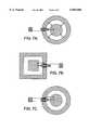
- FIGS. 7A-7Cillustrate alternative arrangements of coaxial coupling systems and methods according to the present invention.
- FIGS. 8A-8Billustrate the use of coupling systems and methods according to the present invention to couple an antenna on the outside of a vehicle to a radiotelephone inside a vehicle.
- an outside antenna 102is provided outside an enclosure such as a vehicle 100.
- the enclosuremay also be a building, as will be described below.
- more than one antennamay be provided, as will be described below.
- the outside antenna 102 outside the vehicle 100is coupled to a radiotelephone 114 inside the vehicle 100 using a through-the-window coaxial coupler 106 and an inside electronic package 110.
- the through-the-window coaxial coupler 106coaxially couples Radio Frequency (RF) signals between the inside surface 104a and outside surface 104b of the window 104.
- the through-the-window coaxial coupler 106includes an inside portion 106a that mounts on the inside surface 104a and an outside portion 106b that mounts on the outside surface 104b.
- the outside portion 106bis coupled to the outside antenna 102 either directly or via a coupling shaft 108 that can include a coaxial cable between the outside portion 106b and the outside antenna 102.
- a preferred design of a coaxial coupler 106will be described in detail below.
- an inside electronic package 110couples the inside portion 106a to a radiotelephone 114, and is located adjacent the inside portion 106a and remote from the radiotelephone 114.
- the electronic packagepreferably includes a receive amplifier that amplifies RF signals that are received from the outside antenna 102 via the through-the-window coaxial coupler 106 and that provides the RF signal so amplified to the radiotelephone 114.
- the electronic packagealso may include a transmit amplifier that amplifies RF signals from the radiotelephone 114 before being passed through the coaxial coupler. The transmit amplifier may raise the transmitted power from the outside antenna 102 to desired levels, as is well known in the art.
- a first cable 116is used to couple the inside portion 106a and the inside electronic package 110
- a second cable 112is used to couple the electronic package 110 and the radiotelephone 114.
- the first cable 116preferably comprises coaxial cable and the second cable 112 preferably comprises coaxial cable.
- the first cable 116may be omitted and the internal electronic package 110 may be formed integral with the inside portion 106a.
- cables other than coaxial cablemay be used to couple the inside portion 106a to the electronic module 110.
- the second cable 112may also include a control cable to couple the inside electronic package 110 and the radiotelephone 114 and/or a power cable to supply power to the inside electronic package 110.
- control and/or powermay be provided via the coaxial cable.
- a wireless connectionmay be provided between the inside electronic package 110 and the radiotelephone 114.
- FIG. 2is a block diagram of an embodiment of an inside electronic package 110 according to the present invention.
- the inside electronic package 110includes a receive amplifier such as a Low Noise Amplifier (LNA) 202 that amplifies RF signals that are received from the outside antenna 102 via the through-the-window coaxial coupler 106 and the first cable 116, and provides the RF signals so amplified to the radiotelephone 114.
- LNALow Noise Amplifier
- Associated filters 204a and 204bmay be provided as is well known to those having skill in the art.
- the inside electronic package 110may also include a transmit amplifier such as an RF power amplifier 212 that amplifies second RF signals that are received from the radiotelephone 114 and that provide the second RF signals so amplified to the antenna 102 via the through-the-window coaxial coupler 106.
- a transmit amplifiersuch as an RF power amplifier 212 that amplifies second RF signals that are received from the radiotelephone 114 and that provide the second RF signals so amplified to the antenna 102 via the through-the-window coaxial coupler 106.
- Associated filters 214a, 214bmay be provided as is well known to those skilled in the art. By including the transmit amplifier 212, precise control of transmit power may be obtained.
- the inside electronic package 110may include a switching system including two switching elements 206a, 206b that switch between the low noise amplifier 202 and the power amplifier 212 to provide half duplex communications, under control of a controller 208 that is responsive to the radiotelephone 114. By including the controller 208, precise timing of transmit bursts may be obtained.
- the second cable 112 between the radiotelephone 114 and the inside electronic module 110may include a coaxial cable 112a that carries the RF signals, one or more power cables 112b that provides power to the power consuming elements of the inside electronic package and one or more control signal cables 112c that can be applied to the controller 208.
- FIG. 3illustrates systems and methods according to the present invention, wherein the enclosure is a building 300.
- a through-the-window coaxial coupler 106coaxially couples RF signals between the inside and outside surfaces 104a and 104b respectively of a window 104.
- the through-the-window coaxial coupler 106includes an inside portion 106a that mounts on the inside surface 104a, and an outside portion 106b that mounts on the outside surface 104b.
- a duplexer 218is included outside the window 104 so that the coaxial coupler 106 may be coupled to more than one antenna 202a, 202b via coupling shafts 208a, 208b respectively.
- the antenna 202amay be a transmit antenna
- the antenna 202bmay be a receive antenna.
- the design of the duplexer 208 to couple to multiple antennas 202a, 202bis well known to those having skill in the art, and need not be described further herein.
- the coaxial couplercan provide a single port connection that can facilitate the use of a duplexer 218 to provide a multiport connection to multiple antennas 202a, 202b.
- an inside electronic package 110is coupled to the inside portion 106a, and is also coupled to a radiotelephone 114 via the second cable 112.
- the design of the inside electronic package 110may be similar to that of FIG. 2, and need not be described again.
- FIG. 4another embodiment of systems and methods that coaxially couple an outside antenna to a radiotelephone through a window according to the present invention is illustrated.
- the link between the inside electronic package 110' and the radiotelephone 114'is a wireless link 406 using a first antenna 402 on the internal electronic package 110' and a second antenna 404 on the radiotelephone 114'. Accordingly, only a power connection may need be provided to the wireless inside electronic package 110'. Control and signal connections may be provided via the wireless link 406.
- the wireless inside electronic package 110'may contain amplifiers, filters, switches and control circuits similar to that described in connection with FIG. 2. However, rather than a second cable 112, a short-range radio frequency transceiver may be used.
- the radiotelephone 114'may be a conventional cellular satellite or other radiotelephone. Alternatively, the radiotelephone 114' may be a short range radiotelephone such as a cordless radiotelephone or a short range transceiver operating under Bluetooth protocol as will be described in detail below.
- the radiotelephone 114'may be any kind of wireless electronic device, such as a laptop computer or a fax machine, as well as a cellular telephone or a cordless telephone.
- the radiotelephone 114'may be a wireless input/output electronic device that includes a microphone, speaker and/or data port.
- the wireless link 406may use infrared or other forms of wireless links.
- FIG. 5is a block diagram of an embodiment of a wireless inside electronic package 110' that uses wireless technology to transmit and receive external radiotelephone signals to and from the radiotelephone.
- the wireless inside electronic package 110'includes a cellular/satellite portion 502 and a short-range wireless portion 504.
- the cellular/satellite portion 502may include a cellular/satellite transceiver 512, a Digital Signal Processor (DSP) 514 and a controller 516, such as a microprocessor controller.
- the transceiveris coupled to inner portion 106a of the coaxial coupler 106 via the first cable 116. It will be understood by those having skill in the art that the cellular/satellite portion 502 preferably is compatible with the cellular/satellite system that is being interfaced to, via the outside antenna 102.
- the short-range wireless portion 504can include a short-range wireless transceiver 522 and a controller 526.
- the short-range wireless transceiver 522transmits and receives messages to and from the radiotelephone 114' via the first antenna 402 and the wireless link 406.
- the short-range wireless portion 504can control the cellular/satellite portion 502.
- the short-range wireless transceivermay be an infrared transceiver or a cordless RF transceiver, such as are used with cordless telephones.
- the short-range wireless portionincludes a Bluetooth transceiver.
- Bluetooth technologyprovides a universal radio interface in the 2.45 GHz frequency band that enables portable electronic devices to connect and communicate wirelessly via short-range ad hoc networks. Bluetooth technology is described for example in Haartsen, "Bluetooth--The Universal Radio Interface for Ad Hoc, Wireless Connectivity", Ericsson Review No. 3, 1998, pp. 110-117, the disclosure of which is hereby incorporated herein by reference. This type of protocol may be used for individuals in a conventional passenger vehicle, as well as taxi service, limousine service, and including bus and other multi-unit enclosures.
- FIGS. 6A, 6B and 6Care a top view, cross-sectional view and bottom view, respectively, of systems and methods for coupling a first coaxial cable to a second coaxial cable through an insulator.
- coupling systems and methods 106couple an outside coaxial cable 12 that includes a first inner conductor 14 and a first shield conductor 16 to a first coaxial cable 116 including a second inner conductor 24 and a second shield conductor 26, through a windshield or other window 104 that includes outside and inside window surfaces 104a and 104b respectively.
- each coaxial cablealso may include an inner insulator and an outer jacket.
- a first center plate 42 and a first surrounding plate 44are adapted for attachment to the outside window surface 104b using adhesive, fasteners and/or other conventional attaching means, such that the first surrounding plate 44 surrounds the first center plate 42 on the outside surface 104b.
- the first center plate 42is electrically connected to the first inner conductor 14 using solder 34a and/or other conventional electrical connecting means.
- the first surrounding plate 44is electrically connected to the first shield conductor 16 using solder 34b and/or other conventional electrical connecting means.
- a second center plate 52 and a second surrounding plate 54also are adapted for attachment to the inside window surface 104a using adhesive, fasteners and/or other conventional attaching means such that the second surrounding plate 54 surrounds the second center plate 52 on the inside window surface 104a.
- the first and second center plates 42 and 52respectively are adjacent one another with the window 104 therebetween.
- the first and second surrounding plates 44 and 54are adjacent one another with the window 104 therebetween.
- the second center plate 52is electrically connected to the second inner conductor 24 using solder 34c and/or other conventional electrical connecting means.
- the second surrounding plate 54is electrically connected to the second shield conductor 26 using solder 34d and/or other electrical connecting means.
- the first and second center plates 42 and 52 respectivelypreferably are first and second disks.
- the first and second surrounding plates 44 and 54 respectivelypreferably are first and second rings.
- the first and second rings 44 and 54 respectivelypreferably are first and second continuous rings.
- polygonal shaped center plates and surrounding platesincluding but not limited to square shaped center plates and surrounding plates may be used, and gaps may be present in the center plates and/or surrounding plates so that they are not continuous.
- a first inductor 46is electrically connected between the first center plate 42 and the first surrounding plate 44 using solder 44e, 44f and/or other conventional electrical connecting means.
- a second inductor 56is electrically connected between the second center plate 52 and the second surrounding plate 54 using solder 54g, 54h and/or other conventional electrical connecting means. More than one inductor also may be electrically connected between a center plate and a surrounding plate as will be described below.
- the coaxial cables 12 and 116 and the inductors 46 and 56may be electrically connected to the center plates and surrounding plates at any arbitrary position thereon. However, preferably, they are connected as illustrated in FIGS. 6A-6C to reduce and preferably minimize unwanted couplings and parasitics. More specifically, the first inner conductor 14 preferably is electrically connected to the first center plate 42 at a first position 42a thereon and the first inductor 46 preferably is electrically connected to the first center plate 42 at a second position 42b that is remote from the first position.
- the second inner conductor 24preferably is electrically connected to the second center plate 52 at a first position 52a thereon and the second inductor 56 preferably is electrically connected to the second center plate 54 at a second position 52b that is remote from the first position 52a.
- the first position 42a on the first center plate 42preferably is adjacent the second position 52b on the second center plate 52.
- the second position 42b on the first center plate 42preferably is adjacent the first position 52a on the second center plate 52.
- the first shield conductor 16preferably is electrically connected to the first surrounding plate 44 at a first position 44a thereon.
- the second shield conductor 26preferably is electrically connected to the second surrounding plate 54 at a second position 54a thereon that is remote from, and preferably opposite, the first position 44a on the first surrounding plate 44.
- the first inductor 46preferably is electrically connected to the first surrounding plate 44 at a second position 44b that is remote from, and more preferably opposite, the first position 44a.
- the second inductor 56is preferably connected to the second surrounding plate 54 at a second position 54b that is remote from, and more preferably opposite, the first position 54a.
- the first and second coaxial cablespreferably emerge from opposite directions and the first inductors preferably are located remote from one another.
- the first center plate 42 and the first surrounding plate 44preferably define a first gap 48 therebetween and the second center plate 52 and the second surrounding plate 54 preferably define a second gap 58 therebetween.
- the first shield conductor 16preferably extends into the first gap and the second shield conductor 26 preferably extends into the second gap 58. More preferably, as shown, the first shield 16 preferably extends midway into the first gap 48 and the second shield 26 preferably extends midway into the second gap 58.
- first and second positions on each of the first center plate 42, first surrounding plate 44, second center plate 52 and second surrounding plate 54may be defined using a tab such as a projecting tab.
- the tabcan facilitate solder connection at the appropriate place on the center plates and surrounding plates.
- the tabsmay be raised and may have a shape that enhances soldering. Multiple layers may be used for the tabs.
- the first and second positions on each of the center plates and surrounding platesneed not be defined by specific features such as tabs.
- a first housing 50contains the first center plate 42 and the first surrounding plate 44.
- a second housing 60contains the second center plate 52 and the second surrounding plate 54.
- the first housing 50also may contain the outside coaxial cable 12 and a first coaxial cable connector 18.
- the second housing 60may also contain the first coaxial cable 116 and a second coaxial cable connector 28. It will be understood however, that the coaxial cable connectors 18 and 28 need not be contained within or be adjacent the housings, and may be eliminated entirely. Similarly, the coaxial cables 12 and 116 themselves may be outside the housings 50 and 60.
- an alignment keysuch as a pair of dimples 36a, 36b may be provided on a respective housing 50 and 60.
- alignment keys 36a, 36bmay be painted or otherwise inscribed on the housings 50 and 60 and also may be provided by virtue of the overall shape of the housings 50 or 60.
- alignment keysneed not be provided at all.
- the materials and dimensions of the center plates, surrounding plates, inductors and housingsmay be varied depending on a particular application.
- the center plates and surrounding platespreferably comprise stamped copper and the housing preferably comprises plastic.
- the surrounding platesmay have an outer diameter of about 45 mm and an inner diameter of about 20 mm.
- the center platemay have a diameter of about 15 mm so that a 2.5 mm gap is present.
- the platesmay be less than 1 mm thick.
- the housingsshould preferably maintain a clear area above and below of about 1 cm.
- the inductorsmay be meandering line inductors rather than coils.
- FIGS. 7A-7CAlternative arrangements of center plates, surrounding plates, and positioning of coaxial cables and inductors are shown in FIGS. 7A-7C.
- the inductancemay be distributed to reduce the difficulty of fabricating small inductor values.
- four-20 nH coilsmay be used to achieve a 5 nH coil.
- FIGS. 8A-8Cillustrate the use of coupling systems and methods according to the present invention to couple an antenna on the exterior of a vehicle to a radiotelephone within a vehicle.
- coupling 106is used to couple a first coaxial cable 108 that is connected to an antenna such as a quadrifilar helical antenna 102 on the roof of a vehicle 100, through the rear window 104 of the vehicle 100, to a second coaxial cable 112 that itself is coupled to a radiotelephone 114 within the vehicle 100.
- FIG. 8Billustrates a similar embodiment to FIG. 8A except that a patch antenna 102' is used on the roof of the vehicle 100. It will be understood that other antennas may be used and other mounting positions for couplers, antennas and transceivers such as radiotelephones may be used. Coupling through windows other than the rear windshield also may be used.
- the present inventionmay be used to coaxially couple two or more conductors through a window.
- a two-conductor circuitcan provide for signal excitation and signal return to complete a circuit. This is known as a "single-port".
- Components having input ports and output ports, known as “two ports” or “multiports”may be cascaded from single ports to modify the signal delivered to the output ports. Examples of such two-ports are transmission lines, duplexers, filters, as well as quadrature matching networks.
- a low loss, two conductor coupling according to the inventioncan enable these above-referred components to become part of the external network.
- the electronic packagepreferably contains a low noise amplifier 202.
- a figure of merit of a radiotelephone to receive signals from an earth orbiting satellitemay be determined principally by the ratio of the antenna gain to the receiver system noise temperature.
- the receiver system noise temperatureis the sum of the receiver noise temperature and the antenna noise temperature.
- the reference point for assessing this ratiois at the input terminals of the receiver system.
- the transmission line lossesare generally included in the antenna temperature according to known formulas, which are described for example in Chapter 17, section 3 of "Antennas, Second Edition", by John D. Kraus, McGraw-Hill, 1988.
- the present inventioncan use this theory in a manner advantageous to mobile communication transceivers used for communication with earth orbiting communication satellites to conveniently satisfy the cable routing requirements while reducing and preferably minimizing the external exposed cabling outside the vehicle.
- the present inventioncan provide efficient coupling from an outside antenna to an inside radiotelephone through a window.
- the inventioncan provide enabling technology that can allow other products to be used in vehicular and/or building environments that may have been too awkward to have been used in the past.
Landscapes
- Transceivers (AREA)
Abstract
Description
Claims (11)
Priority Applications (6)
| Application Number | Priority Date | Filing Date | Title |
|---|---|---|---|
| US09/248,434US6069588A (en) | 1999-02-11 | 1999-02-11 | Systems and methods for coaxially coupling an antenna to a radiotelephone through a window and amplifying signals adjacent and inside the window |
| JP2000601704AJP2002543555A (en) | 1999-02-11 | 2000-01-31 | Apparatus and method for coaxially coupling an antenna through an insulator to amplify signals near the insulator |
| AU27469/00AAU2746900A (en) | 1999-02-11 | 2000-01-31 | Systems and methods for coaxially coupling an antenna through an insulator and for amplifying signals adjacent the insulator |
| CN00803696.9ACN1340224A (en) | 1999-02-11 | 2000-01-31 | Systems and methods for coaxially coupling an antanne through an insulator and for amplifying signals adjacent the insulator |
| DE10084156TDE10084156T1 (en) | 1999-02-11 | 2000-01-31 | Systems and methods for coaxially coupling an antenna through an isolator and amplifying signals adjacent to the isolator |
| PCT/US2000/002346WO2000051199A2 (en) | 1999-02-11 | 2000-01-31 | Systems and methods for coaxially coupling an antenna through an insulator and for amplifying signals adjacent the insulator |
Applications Claiming Priority (1)
| Application Number | Priority Date | Filing Date | Title |
|---|---|---|---|
| US09/248,434US6069588A (en) | 1999-02-11 | 1999-02-11 | Systems and methods for coaxially coupling an antenna to a radiotelephone through a window and amplifying signals adjacent and inside the window |
Publications (1)
| Publication Number | Publication Date |
|---|---|
| US6069588Atrue US6069588A (en) | 2000-05-30 |
Family
ID=22939113
Family Applications (1)
| Application Number | Title | Priority Date | Filing Date |
|---|---|---|---|
| US09/248,434Expired - LifetimeUS6069588A (en) | 1999-02-11 | 1999-02-11 | Systems and methods for coaxially coupling an antenna to a radiotelephone through a window and amplifying signals adjacent and inside the window |
Country Status (1)
| Country | Link |
|---|---|
| US (1) | US6069588A (en) |
Cited By (123)
| Publication number | Priority date | Publication date | Assignee | Title |
|---|---|---|---|---|
| US6232926B1 (en)* | 1999-11-10 | 2001-05-15 | Xm Satellite Radio Inc. | Dual coupled vehicle glass mount antenna system |
| US20010021640A1 (en)* | 2000-02-21 | 2001-09-13 | Dirk Lappe | Motor vehicle wireless telephone system |
| US6295037B1 (en)* | 1999-03-03 | 2001-09-25 | Will Thomas Williams | Emergency television antenna |
| US20010039199A1 (en)* | 2000-04-28 | 2001-11-08 | Takashi Shinzaki | Mobile electronic apparatus, and battery pack for the apparatus |
| US6340928B1 (en)* | 2000-06-22 | 2002-01-22 | Trw Inc. | Emergency assistance system using bluetooth technology |
| US20020019246A1 (en)* | 1999-06-14 | 2002-02-14 | Forte Stephen P. | Method and apparatus for communicating via virtual office telephone extensions |
| WO2002014112A1 (en)* | 2000-08-17 | 2002-02-21 | Siemens Aktiengesellschaft | System and method for transmitting signals in vehicles |
| DE10040307A1 (en)* | 2000-08-14 | 2002-03-07 | Comsys Comm Systems Service Gm | Passive repeater for mobile radio applications in vehicles, has external and internal glass plates which are connected by band connectors |
| US20020032510A1 (en)* | 2000-04-06 | 2002-03-14 | Turnbull Robert R. | Vehicle rearview mirror assembly incorporating a communication system |
| WO2002025967A1 (en)* | 2000-09-22 | 2002-03-28 | Widcomm Inc. | Wireless network and method for providing improved handoff performance |
| US20020066115A1 (en)* | 2000-11-29 | 2002-05-30 | Heino Wendelrup | Portable communications device |
| US20020065065A1 (en)* | 2000-11-30 | 2002-05-30 | E. Michael Lunsford | Method and system for applying line of sight IR selection of a receiver to implement secure transmission of data to a mobile computing device via an RF link |
| US20020065041A1 (en)* | 2000-11-30 | 2002-05-30 | Lunsford E. Michael | Method and system for wirelessly autodialing a telephone number from a record stored on a personal information device |
| US6400326B1 (en)* | 1999-08-03 | 2002-06-04 | Denso Corporation, Ltd. | Antenna booster system for automobile |
| EP1211899A1 (en)* | 2000-11-29 | 2002-06-05 | TELEFONAKTIEBOLAGET L M ERICSSON (publ) | A portable communications device |
| US20020069360A1 (en)* | 2000-03-30 | 2002-06-06 | Martin Thoone | Motor vehicle navigation system having a protected storage medium |
| US20020069417A1 (en)* | 2000-08-30 | 2002-06-06 | Avi Kliger | Home network system and method |
| US6405027B1 (en)* | 1999-12-08 | 2002-06-11 | Philips Electronics N.A. Corporation | Group call for a wireless mobile communication device using bluetooth |
| US6421018B1 (en)* | 2001-05-31 | 2002-07-16 | Andrew Corporation | Bowtie inductive coupler |
| US20020098854A1 (en)* | 2000-12-04 | 2002-07-25 | Michael Becker | Motor vehicle data communication network |
| US6430395B2 (en) | 2000-04-07 | 2002-08-06 | Commil Ltd. | Wireless private branch exchange (WPBX) and communicating between mobile units and base stations |
| US6433685B1 (en)* | 2001-03-02 | 2002-08-13 | Hewlett-Packard Company | System and method for locating lost or stolen articles |
| US20020111157A1 (en)* | 2000-12-04 | 2002-08-15 | Stieber Jon R. | Wireless networked cash management system |
| US6448906B1 (en)* | 1999-10-27 | 2002-09-10 | Intel Corporation | Wireless detection of electronic devices |
| NL1017593C2 (en)* | 2001-03-14 | 2002-09-17 | Asm Int | Inspection system for process devices for treating substrates, as well as a sensor intended for such an inspection system and a method for inspecting process devices. |
| US20020159402A1 (en)* | 1998-07-28 | 2002-10-31 | Yehuda Binder | Local area network of serial intelligent cells |
| US6484027B1 (en)* | 1998-06-15 | 2002-11-19 | Sbc Technology Resources, Inc. | Enhanced wireless handset, including direct handset-to-handset communication mode |
| US20020188863A1 (en)* | 2001-05-11 | 2002-12-12 | Solomon Friedman | System, method and apparatus for establishing privacy in internet transactions and communications |
| US20020194605A1 (en)* | 2001-05-18 | 2002-12-19 | T.M.T. Third Millenium Technologies Ltd. | Cableran networking over coaxial cables |
| US20020194383A1 (en)* | 2001-02-13 | 2002-12-19 | T.M.T. Third Millenium Technologies Ltd. | Cableran home networking over coaxial cables |
| US20020197955A1 (en)* | 1999-05-26 | 2002-12-26 | Johnson Controls Technology Company | Wireless communications system and method |
| US20030028902A1 (en)* | 2001-07-11 | 2003-02-06 | Cubley H. Dean | Set-top box having an improved patch antenna |
| US20030054793A1 (en)* | 2001-08-17 | 2003-03-20 | Manis Constantine N. | Coupling between power line and customer in power line communication system |
| US6538609B2 (en) | 1999-11-10 | 2003-03-25 | Xm Satellite Radio Inc. | Glass-mountable antenna system with DC and RF coupling |
| US20030066082A1 (en)* | 2000-08-30 | 2003-04-03 | Avi Kliger | Home network system and method |
| US20030069996A1 (en)* | 1999-08-30 | 2003-04-10 | William M. Parrott | Infrared to radio frequency adapter and method for using the same |
| EP1308306A1 (en)* | 2001-11-05 | 2003-05-07 | Agilent Technologies Inc. (a Delaware Corporation) | Wireless control of a print carriage |
| US20030169180A1 (en)* | 2002-03-08 | 2003-09-11 | Hardman Simon F. | Cooperative vending machine data reporting |
| US20030179153A1 (en)* | 2000-05-28 | 2003-09-25 | Marco Schnurer | Antenna for automobiles and set of components for the same |
| US6650871B1 (en)* | 1999-10-14 | 2003-11-18 | Agere Systems Inc. | Cordless RF range extension for wireless piconets |
| US20040017292A1 (en)* | 2002-07-29 | 2004-01-29 | Johnson Controls Technology Company | System and method of communicating home security data between a vehicle and a home |
| US6686882B2 (en) | 2000-10-19 | 2004-02-03 | Xm Satellite Radio, Inc. | Apparatus and method for transferring DC power and RF energy through a dielectric for antenna reception |
| US20040032373A1 (en)* | 2002-08-14 | 2004-02-19 | Argy Petros | Combination satellite and terrestrial antenna |
| US20040048622A1 (en)* | 1999-05-26 | 2004-03-11 | Johnson Controls Technology Company | System and method for radio frequency communication with a personal digital assistant in a vehicle |
| US20040110472A1 (en)* | 2002-04-23 | 2004-06-10 | Johnson Controls Technology Company | Wireless communication system and method |
| US6766461B1 (en)* | 1999-11-30 | 2004-07-20 | Kabushiki Kaisha Toshiba | Status switching method of an information apparatus to ensure an operating status when the apparatus is liable to receive vibration or shock |
| US20040177381A1 (en)* | 2002-09-05 | 2004-09-09 | Tiaris, Inc. | Home network system which supports legacy digital set top box devices |
| US20040203379A1 (en)* | 2002-04-23 | 2004-10-14 | Johnson Controls Technology Company | Bluetooth transmission of vehicle diagnostic information |
| US20040246607A1 (en)* | 2003-05-19 | 2004-12-09 | Watson Alan R. | Rearview mirror assemblies incorporating hands-free telephone components |
| US20040266425A1 (en)* | 2003-06-24 | 2004-12-30 | Sbc, Inc. | Wireless wide area network charger and cradle |
| US20050020214A1 (en)* | 2003-07-25 | 2005-01-27 | Timothy Neill | Wireless communication system |
| US20050031344A1 (en)* | 2001-03-08 | 2005-02-10 | Hidenori Sato | Wireless communication repeater-built-in vehicle-use mirror device |
| US20050054335A1 (en)* | 2003-09-04 | 2005-03-10 | Sbc Knowledge Ventures, L.P. | Call forwarding control device and method of call management |
| US20050064853A1 (en)* | 2003-09-23 | 2005-03-24 | Sbc Knowledge Ventures, L.P. | Unified telephone handset for personal communications based on wireline and wireless network convergence |
| US20050064855A1 (en)* | 2003-09-23 | 2005-03-24 | Sbc Knowledge Ventures, L.P. | Method and system for forwarding wireless communications |
| US20050063528A1 (en)* | 2003-09-23 | 2005-03-24 | Sbc Knowledge Ventures, L.P. | Location based call routing for call answering services |
| US6876845B1 (en)* | 1999-09-06 | 2005-04-05 | Honda Giken Kogyo Kabushiki Kaisha | Radio communication system for vehicle |
| US20050096024A1 (en)* | 2003-11-05 | 2005-05-05 | Sbc Knowledge Ventures, L.P. | System and method of transitioning between cellular and voice over internet protocol communication |
| US6909946B1 (en) | 2002-10-31 | 2005-06-21 | Garmin Ltd. | System and method for wirelessly linking electronic marine components |
| US20050277431A1 (en)* | 2004-06-14 | 2005-12-15 | Sbc Knowledge Ventures, Lp | System and method for managing wireless data communications |
| US20060003806A1 (en)* | 2004-07-02 | 2006-01-05 | Sbc Knowledge Ventures, L.P. | Phone synchronization device and method of handling personal information |
| US20060062580A1 (en)* | 2004-09-22 | 2006-03-23 | Kamran Mahbobi | Apparatus and method for transferring DC power and RF signals through a transparent or substantially transparent medium for antenna reception |
| US20060062515A1 (en)* | 2004-09-22 | 2006-03-23 | Kamran Mahbobi | Apparatus and method for transmitting electrical power through a transparent or substantially transparent medium |
| US20060133465A1 (en)* | 2004-12-21 | 2006-06-22 | Dockemeyer Joseph R Jr | Wireless home repeater for satellite radio products |
| US20070004338A1 (en)* | 2005-07-01 | 2007-01-04 | Research In Motion Limited | Determination of antenna noise temperature for handheld wireless devices |
| US7162020B1 (en) | 1999-06-14 | 2007-01-09 | Ascendent Telecommunications, Inc. | Method and apparatus for selectively establishing communication with one of plural devices associated with a single telephone number |
| US20070021157A1 (en)* | 2005-07-25 | 2007-01-25 | Sin Etke Technology Co., Ltd. | Short-distance wireless transmission system for data transmission among electronic devices on a vehicle |
| US7177738B2 (en) | 2001-05-30 | 2007-02-13 | Alpine Electronics, Inc. | Vehicle management system |
| EP1413147A4 (en)* | 2001-02-13 | 2007-03-14 | T M T Third Millenium Technolo | Cableran networking over coaxial cables |
| US20070070911A1 (en)* | 2005-09-29 | 2007-03-29 | Goldberg Keith J | Method for testing links in a wireless network |
| US20070091915A1 (en)* | 2000-04-19 | 2007-04-26 | Serconet Ltd. | Network combining wired and non wired segments |
| US7254400B1 (en)* | 1999-10-14 | 2007-08-07 | Mitsubishi Denki Kabushiki Kaisha | Wireless terminal communication method |
| US7292858B2 (en) | 1999-06-14 | 2007-11-06 | Ascendent Telecommunications, Inc. | Method and apparatus for communicating with one of plural devices associated with a single telephone number during a disaster and disaster recovery |
| US20070259688A1 (en)* | 2000-06-14 | 2007-11-08 | Forte Stephen P | Method and apparatus for communicating via virtual office telephone extensions |
| US20070275595A1 (en)* | 2004-02-16 | 2007-11-29 | Serconet Ltd. | Outlet add-on module |
| US20070279304A1 (en)* | 2006-05-30 | 2007-12-06 | Guy-Aymar Chakam | Antenna module for a motor vehicle |
| US7352328B2 (en) | 2005-09-27 | 2008-04-01 | Samsung Electronics Co., Ltd. | Flat-plate MIMO array antenna with isolation element |
| US20080117929A1 (en)* | 2006-11-20 | 2008-05-22 | Broadcom Corporation | System and method for retransmitting packets over a network of communication channels |
| US20080130779A1 (en)* | 2006-11-20 | 2008-06-05 | Broadcom Corporation | Apparatus and methods for compensating for signal imbalance in a receiver |
| US20080178229A1 (en)* | 2000-08-30 | 2008-07-24 | Broadcom Corporation | Home network system and method |
| US20080205606A1 (en)* | 2002-11-13 | 2008-08-28 | Serconet Ltd. | Addressable outlet, and a network using the same |
| US20080259957A1 (en)* | 2006-11-20 | 2008-10-23 | Broadcom Corporation | Mac to phy interface apparatus and methods for transmission of packets through a communications network |
| US20080298241A1 (en)* | 2007-05-31 | 2008-12-04 | Broadcomm Corporation | Apparatus and methods for reduction of transmission delay in a communication network |
| US20090165070A1 (en)* | 2007-12-19 | 2009-06-25 | Broadcom Corporation | SYSTEMS AND METHODS FOR PROVIDING A MoCA COMPATABILITY STRATEGY |
| US7555011B2 (en) | 2001-02-16 | 2009-06-30 | University Of Maryland, College Park | SEAMA:a source encoding assisted multiple access protocol for wireless communication |
| US7656904B2 (en) | 2003-03-13 | 2010-02-02 | Mosaid Technologies Incorporated | Telephone system having multiple distinct sources and accessories therefor |
| US20100031297A1 (en)* | 2008-07-31 | 2010-02-04 | Broadcom Corporation | SYSTEMS AND METHODS FOR PROVIDING A MoCA POWER MANAGEMENT STRATEGY |
| US7688841B2 (en) | 2003-07-09 | 2010-03-30 | Mosaid Technologies Incorporated | Modular outlet |
| US7697522B2 (en) | 2006-11-20 | 2010-04-13 | Broadcom Corporation | Systems and methods for aggregation of packets for transmission through a communications network |
| US20100099451A1 (en)* | 2008-06-20 | 2010-04-22 | Mobileaccess Networks Ltd. | Method and System for Real Time Control of an Active Antenna Over a Distributed Antenna System |
| US20100158021A1 (en)* | 2008-12-22 | 2010-06-24 | Broadcom Corporation | Systems and methods for physical layer ("phy") concatenation in a moca network |
| US20100158013A1 (en)* | 2008-12-22 | 2010-06-24 | Broadcom Corporation | Systems and methods for reducing latency and reservation request overhead in a communications network |
| US20100246586A1 (en)* | 2009-03-30 | 2010-09-30 | Yitshak Ohana | Systems and methods for retransmitting packets over a network of communication channels |
| US7813451B2 (en) | 2006-01-11 | 2010-10-12 | Mobileaccess Networks Ltd. | Apparatus and method for frequency shifting of a wireless signal and systems using frequency shifting |
| US20100284474A1 (en)* | 2009-05-05 | 2010-11-11 | Broadcom Corporation | Transmitter channel throughput in an information network |
| US7860084B2 (en) | 2001-10-11 | 2010-12-28 | Mosaid Technologies Incorporated | Outlet with analog signal adapter, a method for use thereof and a network using said outlet |
| US7925320B2 (en) | 2006-03-06 | 2011-04-12 | Garmin Switzerland Gmbh | Electronic device mount |
| US8005204B2 (en) | 2005-06-03 | 2011-08-23 | At&T Intellectual Property I, L.P. | Call routing system and method of using the same |
| US20110206042A1 (en)* | 2010-02-23 | 2011-08-25 | Moshe Tarrab | Systems and methods for implementing a high throughput mode for a moca device |
| US8098770B2 (en) | 2008-05-06 | 2012-01-17 | Broadcom Corporation | Unbiased signal-to-noise ratio estimation for receiver having channel estimation error |
| US8200214B2 (en) | 2006-10-11 | 2012-06-12 | Johnson Controls Technology Company | Wireless network selection |
| US8238227B2 (en) | 2008-12-22 | 2012-08-07 | Broadcom Corporation | Systems and methods for providing a MoCA improved performance for short burst packets |
| US8244307B1 (en)* | 1999-05-11 | 2012-08-14 | Continental Automotive Gmbh | System allowing hands free use of a mobile phone in conjunction with a vehicle transceiver |
| US8280030B2 (en) | 2005-06-03 | 2012-10-02 | At&T Intellectual Property I, Lp | Call routing system and method of using the same |
| US8325759B2 (en) | 2004-05-06 | 2012-12-04 | Corning Mobileaccess Ltd | System and method for carrying a wireless based signal over wiring |
| US8363797B2 (en) | 2000-03-20 | 2013-01-29 | Mosaid Technologies Incorporated | Telephone outlet for implementing a local area network over telephone lines and a local area network using such outlets |
| US8582598B2 (en) | 1999-07-07 | 2013-11-12 | Mosaid Technologies Incorporated | Local area network for distributing data communication, sensing and control signals |
| US8588679B1 (en)* | 2004-01-08 | 2013-11-19 | Iwao Fujisaki | Carrier |
| US8594133B2 (en) | 2007-10-22 | 2013-11-26 | Corning Mobileaccess Ltd. | Communication system using low bandwidth wires |
| US8611327B2 (en) | 2010-02-22 | 2013-12-17 | Broadcom Corporation | Method and apparatus for policing a QoS flow in a MoCA 2.0 network |
| US8751232B2 (en) | 2004-08-12 | 2014-06-10 | At&T Intellectual Property I, L.P. | System and method for targeted tuning of a speech recognition system |
| US8824659B2 (en) | 2005-01-10 | 2014-09-02 | At&T Intellectual Property I, L.P. | System and method for speech-enabled call routing |
| US8867355B2 (en) | 2009-07-14 | 2014-10-21 | Broadcom Corporation | MoCA multicast handling |
| US8897215B2 (en) | 2009-02-08 | 2014-11-25 | Corning Optical Communications Wireless Ltd | Communication system using cables carrying ethernet signals |
| US8942250B2 (en) | 2009-10-07 | 2015-01-27 | Broadcom Corporation | Systems and methods for providing service (“SRV”) node selection |
| US9112972B2 (en) | 2004-12-06 | 2015-08-18 | Interactions Llc | System and method for processing speech |
| EP2388708B1 (en) | 2001-03-20 | 2015-10-28 | Sipco Llc | Wireless transceiver for use in a wireless communication network |
| US9184960B1 (en) | 2014-09-25 | 2015-11-10 | Corning Optical Communications Wireless Ltd | Frequency shifting a communications signal(s) in a multi-frequency distributed antenna system (DAS) to avoid or reduce frequency interference |
| US9338823B2 (en) | 2012-03-23 | 2016-05-10 | Corning Optical Communications Wireless Ltd | Radio-frequency integrated circuit (RFIC) chip(s) for providing distributed antenna system functionalities, and related components, systems, and methods |
| US9531619B2 (en) | 2009-04-07 | 2016-12-27 | Broadcom Corporation | Channel assessment in an information network |
| CN110537290A (en)* | 2017-04-20 | 2019-12-03 | 奥迪股份公司 | Automobile-use with shell, for antenna impedance adaptation Changer Device and the Changer Device with assembly motor vehicle |
| US20200204212A1 (en)* | 2018-12-20 | 2020-06-25 | Arris Enterprises Llc | Last meter wireless broadband |
| US10986165B2 (en) | 2004-01-13 | 2021-04-20 | May Patents Ltd. | Information device |
Citations (9)
| Publication number | Priority date | Publication date | Assignee | Title |
|---|---|---|---|---|
| US2829367A (en)* | 1953-02-26 | 1958-04-01 | Robert F Rychlik | Television lead-in coupler |
| US4621243A (en)* | 1984-12-30 | 1986-11-04 | Harada Kogyo Kabushiki Kaisha | Transmission channel coupler for antenna |
| US4764773A (en)* | 1985-07-30 | 1988-08-16 | Larsen Electronics, Inc. | Mobile antenna and through-the-glass impedance matched feed system |
| US4839660A (en)* | 1983-09-23 | 1989-06-13 | Orion Industries, Inc. | Cellular mobile communication antenna |
| US5099252A (en)* | 1989-12-08 | 1992-03-24 | Larsen Electronics, Inc. | Mobile cellular antenna system |
| US5212492A (en)* | 1990-04-09 | 1993-05-18 | Andrew Jesman | Matching element for mobile antenna |
| US5451966A (en)* | 1994-09-23 | 1995-09-19 | The Antenna Company | Ultra-high frequency, slot coupled, low-cost antenna system |
| US5600333A (en)* | 1995-01-26 | 1997-02-04 | Larsen Electronics, Inc. | Active repeater antenna assembly |
| US5828946A (en)* | 1996-11-22 | 1998-10-27 | Lucent Technologies Inc. | CATV-based wireless communications scheme |
- 1999
- 1999-02-11USUS09/248,434patent/US6069588A/ennot_activeExpired - Lifetime
Patent Citations (10)
| Publication number | Priority date | Publication date | Assignee | Title |
|---|---|---|---|---|
| US2829367A (en)* | 1953-02-26 | 1958-04-01 | Robert F Rychlik | Television lead-in coupler |
| US4839660A (en)* | 1983-09-23 | 1989-06-13 | Orion Industries, Inc. | Cellular mobile communication antenna |
| US4621243A (en)* | 1984-12-30 | 1986-11-04 | Harada Kogyo Kabushiki Kaisha | Transmission channel coupler for antenna |
| US4764773A (en)* | 1985-07-30 | 1988-08-16 | Larsen Electronics, Inc. | Mobile antenna and through-the-glass impedance matched feed system |
| US5099252A (en)* | 1989-12-08 | 1992-03-24 | Larsen Electronics, Inc. | Mobile cellular antenna system |
| US5155494A (en)* | 1989-12-08 | 1992-10-13 | Larsen Electronics, Inc. | Vehicle antenna system |
| US5212492A (en)* | 1990-04-09 | 1993-05-18 | Andrew Jesman | Matching element for mobile antenna |
| US5451966A (en)* | 1994-09-23 | 1995-09-19 | The Antenna Company | Ultra-high frequency, slot coupled, low-cost antenna system |
| US5600333A (en)* | 1995-01-26 | 1997-02-04 | Larsen Electronics, Inc. | Active repeater antenna assembly |
| US5828946A (en)* | 1996-11-22 | 1998-10-27 | Lucent Technologies Inc. | CATV-based wireless communications scheme |
Non-Patent Citations (4)
| Title |
|---|
| Haartsen, "Bluetooth--The Universal Radio Interference For Ad Hoc, Wireless Connectivity", Ericsson Review, No. 3, 1998, pp. 110-117. |
| Haartsen, Bluetooth The Universal Radio Interference For Ad Hoc, Wireless Connectivity , Ericsson Review, No. 3, 1998, pp. 110 117.* |
| Kraus, "System Temperature and Signal-to-Noise Ratio", Antennas, Second Edition, McGraw-Hill, 1988, pp. 782-787. |
| Kraus, System Temperature and Signal to Noise Ratio , Antennas, Second Edition, McGraw Hill, 1988, pp. 782 787.* |
Cited By (314)
| Publication number | Priority date | Publication date | Assignee | Title |
|---|---|---|---|---|
| US20110124316A1 (en)* | 1998-06-15 | 2011-05-26 | Bertrum Technologies Llc | Enhanced wireless handset, including direct handset-to-handset communication mode |
| US9503840B2 (en) | 1998-06-15 | 2016-11-22 | Intellectual Ventures I Llc | Enhanced wireless handset, including direct handset-to-handset communication mode |
| US20050159107A1 (en)* | 1998-06-15 | 2005-07-21 | Sbc Technology Resources, Inc. | Enhanced wireless handset, including direct handset-to-handset communication mode |
| US6865372B2 (en) | 1998-06-15 | 2005-03-08 | Sbc Technology Resources, Inc. | Enhanced wireless handset, including direct handset-to-handset communication mode |
| US20050032475A1 (en)* | 1998-06-15 | 2005-02-10 | Sbc, Inc. | Enhanced wireless handset, including direct handset-to-handset communication mode |
| US20050020236A1 (en)* | 1998-06-15 | 2005-01-27 | Sbc, Inc. | Enhanced wireless handset, including direct handset-to-handset communication mode |
| US7353018B2 (en) | 1998-06-15 | 2008-04-01 | Bertrum Technologies Llc | Enhanced wireless handset, including direct handset-to-handset communication mode |
| US20040116073A1 (en)* | 1998-06-15 | 2004-06-17 | Sbc, Inc. | Enhanced wireless handset, including direct handset-to-handset communication mode |
| US7403793B2 (en) | 1998-06-15 | 2008-07-22 | Bertrum Technologies Llc | Enhanced wireless handset, including direct handset-to-handset communication mode |
| US8019381B2 (en) | 1998-06-15 | 2011-09-13 | Bertrum Technologies Llc | Enhanced wireless handset, including direct handset-to-handset communication mode |
| US8265691B2 (en) | 1998-06-15 | 2012-09-11 | Bertrum Technologies Llc | Enhanced wireless handset, including direct handset-to-handset communication mode |
| US8792828B2 (en) | 1998-06-15 | 2014-07-29 | Bertrum Technologies Llc | Enhanced wireless handset, including direct handset-to-handset communication mode |
| US7693542B2 (en) | 1998-06-15 | 2010-04-06 | Daniel Wayne Mauney | Enhanced wireless handset, including direct handset-to-handset communication mode |
| US6484027B1 (en)* | 1998-06-15 | 2002-11-19 | Sbc Technology Resources, Inc. | Enhanced wireless handset, including direct handset-to-handset communication mode |
| US20100178869A1 (en)* | 1998-06-15 | 2010-07-15 | Bertrum Technologies Llc | Enhanced wireless handset, including direct handset-to-handset communication mode |
| US7885684B2 (en) | 1998-06-15 | 2011-02-08 | Bertrum Technologies Llc | Enhanced wireless handset, including direct handset-to-handset communication mode |
| US8346169B2 (en) | 1998-06-15 | 2013-01-01 | Bertrum Technologies Llc | Enhanced wireless handset, including direct handset-to-handset communication mode |
| US7852874B2 (en) | 1998-07-28 | 2010-12-14 | Mosaid Technologies Incorporated | Local area network of serial intelligent cells |
| US7016368B2 (en) | 1998-07-28 | 2006-03-21 | Serconet, Ltd. | Local area network of serial intelligent cells |
| US8325636B2 (en) | 1998-07-28 | 2012-12-04 | Mosaid Technologies Incorporated | Local area network of serial intelligent cells |
| US7965735B2 (en) | 1998-07-28 | 2011-06-21 | Mosaid Technologies Incorporated | Local area network of serial intelligent cells |
| US7035280B2 (en) | 1998-07-28 | 2006-04-25 | Serconet Ltd. | Local area network of serial intelligent cells |
| US8908673B2 (en) | 1998-07-28 | 2014-12-09 | Conversant Intellectual Property Management Incorporated | Local area network of serial intelligent cells |
| US7095756B2 (en) | 1998-07-28 | 2006-08-22 | Serconet, Ltd. | Local area network of serial intelligent cells |
| US20060251110A1 (en)* | 1998-07-28 | 2006-11-09 | Isreali Company Of Serconet Ltd. | Local area network of serial intelligent cells |
| US20040174897A1 (en)* | 1998-07-28 | 2004-09-09 | Israeli Company Of Serconet Ltd. | Local area network of serial intellegent cells |
| US7830858B2 (en) | 1998-07-28 | 2010-11-09 | Mosaid Technologies Incorporated | Local area network of serial intelligent cells |
| US20040170189A1 (en)* | 1998-07-28 | 2004-09-02 | Israeli Company Of Serconet Ltd. | Local area network of serial intellegent cells |
| US7292600B2 (en) | 1998-07-28 | 2007-11-06 | Serconet Ltd. | Local area network of serial intellegent cells |
| US20020159402A1 (en)* | 1998-07-28 | 2002-10-31 | Yehuda Binder | Local area network of serial intelligent cells |
| US7424031B2 (en) | 1998-07-28 | 2008-09-09 | Serconet, Ltd. | Local area network of serial intelligent cells |
| US7978726B2 (en) | 1998-07-28 | 2011-07-12 | Mosaid Technologies Incorporated | Local area network of serial intelligent cells |
| US7221679B2 (en) | 1998-07-28 | 2007-05-22 | Serconet Ltd. | Local area network of serial intelligent cells |
| US7006523B2 (en) | 1998-07-28 | 2006-02-28 | Serconet Ltd. | Local area network of serial intelligent cells |
| US8885660B2 (en) | 1998-07-28 | 2014-11-11 | Conversant Intellectual Property Management Incorporated | Local area network of serial intelligent cells |
| US7986708B2 (en) | 1998-07-28 | 2011-07-26 | Mosaid Technologies Incorporated | Local area network of serial intelligent cells |
| US8885659B2 (en) | 1998-07-28 | 2014-11-11 | Conversant Intellectual Property Management Incorporated | Local area network of serial intelligent cells |
| US7653015B2 (en) | 1998-07-28 | 2010-01-26 | Mosaid Technologies Incorporated | Local area network of serial intelligent cells |
| US8270430B2 (en) | 1998-07-28 | 2012-09-18 | Mosaid Technologies Incorporated | Local area network of serial intelligent cells |
| US20060018339A1 (en)* | 1998-07-28 | 2006-01-26 | Serconet, Ltd | Local area network of serial intelligent cells |
| US20050013320A1 (en)* | 1998-07-28 | 2005-01-20 | Serconet Ltd. | Local area network of serial intelligent cells |
| US7187695B2 (en) | 1998-07-28 | 2007-03-06 | Serconet Ltd. | Local area network of serial intelligent cells |
| US20050163152A1 (en)* | 1998-07-28 | 2005-07-28 | Serconet Ltd. | Local area network of serial intelligent cells |
| US8867523B2 (en) | 1998-07-28 | 2014-10-21 | Conversant Intellectual Property Management Incorporated | Local area network of serial intelligent cells |
| US6295037B1 (en)* | 1999-03-03 | 2001-09-25 | Will Thomas Williams | Emergency television antenna |
| US8244307B1 (en)* | 1999-05-11 | 2012-08-14 | Continental Automotive Gmbh | System allowing hands free use of a mobile phone in conjunction with a vehicle transceiver |
| US9370041B2 (en)* | 1999-05-26 | 2016-06-14 | Visteon Global Technologies, Inc. | Wireless communications system and method |
| US20030228879A1 (en)* | 1999-05-26 | 2003-12-11 | Johnson Controls Technology Company | Communication system for vehicle |
| US20110227698A1 (en)* | 1999-05-26 | 2011-09-22 | Johnson Controls Technology Company | Wireless control system and method |
| US20080161047A1 (en)* | 1999-05-26 | 2008-07-03 | Johnson Controls Technology Company | System and method for radio frequency communication with a personal digital assistant in a vehicle |
| US20020197955A1 (en)* | 1999-05-26 | 2002-12-26 | Johnson Controls Technology Company | Wireless communications system and method |
| US20040048622A1 (en)* | 1999-05-26 | 2004-03-11 | Johnson Controls Technology Company | System and method for radio frequency communication with a personal digital assistant in a vehicle |
| US20050090279A9 (en)* | 1999-05-26 | 2005-04-28 | Johnson Controls Technology Company | Communication system for vehicle |
| US8634888B2 (en)* | 1999-05-26 | 2014-01-21 | Johnson Controls Technology Company | Wireless control system and method |
| US20130285796A1 (en)* | 1999-05-26 | 2013-10-31 | Johnson Controls Technology Company | Wireless communications system and method |
| US7257426B1 (en) | 1999-05-26 | 2007-08-14 | Johnson Controls Technology Company | Wireless communications systems and method |
| US8494449B2 (en) | 1999-05-26 | 2013-07-23 | Johnson Controls Technology Company | Wireless communications system and method |
| US9318017B2 (en) | 1999-05-26 | 2016-04-19 | Visteon Global Technologies, Inc. | Wireless control system and method |
| US8380251B2 (en) | 1999-05-26 | 2013-02-19 | Johnson Controls Technology Company | Wireless communications system and method |
| US7349722B2 (en)* | 1999-05-26 | 2008-03-25 | Johnson Controls Technology Company | Wireless communications system and method |
| US7346374B2 (en) | 1999-05-26 | 2008-03-18 | Johnson Controls Technology Company | Wireless communications system and method |
| US20080045274A1 (en)* | 1999-05-26 | 2008-02-21 | Johnson Controls Technology Company | Wireless communications system and method |
| US7970446B2 (en)* | 1999-05-26 | 2011-06-28 | Johnson Controls Technology Company | Wireless control system and method |
| US8897708B2 (en) | 1999-05-26 | 2014-11-25 | Johnson Controls Technology Company | Wireless communications system and method |
| US8233603B2 (en) | 1999-06-14 | 2012-07-31 | Ascendent Telecommunications, Inc. | Method and apparatus for communicating with one of plural devices associated with a single telephone number |
| US7162020B1 (en) | 1999-06-14 | 2007-01-09 | Ascendent Telecommunications, Inc. | Method and apparatus for selectively establishing communication with one of plural devices associated with a single telephone number |
| US20080032716A1 (en)* | 1999-06-14 | 2008-02-07 | Forte Stephen P | Method and apparatus for selectively establishing communication with one of plural devices associated with a single telephone number |
| US8447352B2 (en) | 1999-06-14 | 2013-05-21 | Ascendent Telecommunications Inc. | Method and apparatus for communicating via virtual office telephone extensions |
| US20020019246A1 (en)* | 1999-06-14 | 2002-02-14 | Forte Stephen P. | Method and apparatus for communicating via virtual office telephone extensions |
| US8135121B2 (en) | 1999-06-14 | 2012-03-13 | Ascendent Telecommunications, Inc. | Method and apparatus for selectively establishing communication with one of plural devices associated with a single telephone number |
| US7292858B2 (en) | 1999-06-14 | 2007-11-06 | Ascendent Telecommunications, Inc. | Method and apparatus for communicating with one of plural devices associated with a single telephone number during a disaster and disaster recovery |
| US8135410B2 (en) | 1999-06-14 | 2012-03-13 | Ascendent Telecommunications, Inc. | Method and apparatus for communicating with one of plural devices associated with a single telephone number during a disaster and disaster recovery |
| US7274782B2 (en) | 1999-06-14 | 2007-09-25 | Ascendent Telecommunications, Inc. | Method and apparatus for selectively establishing communication with one of plural devices associated with a single telephone number |
| US7305079B1 (en) | 1999-06-14 | 2007-12-04 | Ascendent Telecommunications, Inc. | Method and apparatus for communicating with one of plural devices associated with a single telephone number |
| US8144856B2 (en) | 1999-06-14 | 2012-03-27 | Ascendent Telecommunications, Inc. | Method and apparatus for communicating with one of plural devices associated with a single telephone number |
| US7440561B2 (en) | 1999-06-14 | 2008-10-21 | Ascendent Telecommunications, Inc. | Method and apparatus for selectively establishing communication with one of plural devices associated with a single telephone number |
| US20070127680A1 (en)* | 1999-06-14 | 2007-06-07 | Forte Stephen P | Method and apparatus for selectively establishing communication with one of plural devices associated with a single telephone number |
| US20080107252A1 (en)* | 1999-06-14 | 2008-05-08 | Forte Stephen P | Method and apparatus for communicating with one of plural devices associated with a single telephone number |
| US8582598B2 (en) | 1999-07-07 | 2013-11-12 | Mosaid Technologies Incorporated | Local area network for distributing data communication, sensing and control signals |
| US6400326B1 (en)* | 1999-08-03 | 2002-06-04 | Denso Corporation, Ltd. | Antenna booster system for automobile |
| US20030069996A1 (en)* | 1999-08-30 | 2003-04-10 | William M. Parrott | Infrared to radio frequency adapter and method for using the same |
| US20050170791A1 (en)* | 1999-09-06 | 2005-08-04 | Honda Giken Kogyo Kabushiki Kaisha | Radio communication system for vehicle |
| US6876845B1 (en)* | 1999-09-06 | 2005-04-05 | Honda Giken Kogyo Kabushiki Kaisha | Radio communication system for vehicle |
| US7233815B2 (en) | 1999-09-06 | 2007-06-19 | Honda Giken Kogyo Kabushiki Kaisha | Radio communication system for vehicle |
| US7254400B1 (en)* | 1999-10-14 | 2007-08-07 | Mitsubishi Denki Kabushiki Kaisha | Wireless terminal communication method |
| US6650871B1 (en)* | 1999-10-14 | 2003-11-18 | Agere Systems Inc. | Cordless RF range extension for wireless piconets |
| US6448906B1 (en)* | 1999-10-27 | 2002-09-10 | Intel Corporation | Wireless detection of electronic devices |
| US6232926B1 (en)* | 1999-11-10 | 2001-05-15 | Xm Satellite Radio Inc. | Dual coupled vehicle glass mount antenna system |
| US6538609B2 (en) | 1999-11-10 | 2003-03-25 | Xm Satellite Radio Inc. | Glass-mountable antenna system with DC and RF coupling |
| US6766461B1 (en)* | 1999-11-30 | 2004-07-20 | Kabushiki Kaisha Toshiba | Status switching method of an information apparatus to ensure an operating status when the apparatus is liable to receive vibration or shock |
| US6405027B1 (en)* | 1999-12-08 | 2002-06-11 | Philips Electronics N.A. Corporation | Group call for a wireless mobile communication device using bluetooth |
| US20010021640A1 (en)* | 2000-02-21 | 2001-09-13 | Dirk Lappe | Motor vehicle wireless telephone system |
| US8855277B2 (en) | 2000-03-20 | 2014-10-07 | Conversant Intellectual Property Managment Incorporated | Telephone outlet for implementing a local area network over telephone lines and a local area network using such outlets |
| US8363797B2 (en) | 2000-03-20 | 2013-01-29 | Mosaid Technologies Incorporated | Telephone outlet for implementing a local area network over telephone lines and a local area network using such outlets |
| US7185369B2 (en)* | 2000-03-30 | 2007-02-27 | Mannesmann Vdo Ag | Motor vehicle navigation system having a protected storage medium |
| US20020069360A1 (en)* | 2000-03-30 | 2002-06-06 | Martin Thoone | Motor vehicle navigation system having a protected storage medium |
| US6980092B2 (en) | 2000-04-06 | 2005-12-27 | Gentex Corporation | Vehicle rearview mirror assembly incorporating a communication system |
| US7772966B2 (en) | 2000-04-06 | 2010-08-10 | Gentex Corporation | Vehicle rearview mirror assembly incorporating a communication system |
| US20070291383A1 (en)* | 2000-04-06 | 2007-12-20 | Gentex Corporation | Rearview assemblies incorporating hands-free telephone components |
| US20060097855A1 (en)* | 2000-04-06 | 2006-05-11 | Turnbull Robert R | Vehicle rearview mirror assembly incorporating a communication system |
| US20020032510A1 (en)* | 2000-04-06 | 2002-03-14 | Turnbull Robert R. | Vehicle rearview mirror assembly incorporating a communication system |
| US7327226B2 (en) | 2000-04-06 | 2008-02-05 | Gentex Corporation | Vehicle rearview mirror assembly incorporating a communication system |
| US8787590B2 (en) | 2000-04-06 | 2014-07-22 | Gentex Corporation | Rearview assemblies incorporating hands-free telephone components |
| US20020160806A1 (en)* | 2000-04-07 | 2002-10-31 | Commil Ltd | Wireless private branch exchange (WPBX) and communicating between mobile units and base stations |
| US7107057B2 (en) | 2000-04-07 | 2006-09-12 | Commil Ltd. | Wireless private branch exchange (WPBX) and communicating between mobile units and base stations |
| US6430395B2 (en) | 2000-04-07 | 2002-08-06 | Commil Ltd. | Wireless private branch exchange (WPBX) and communicating between mobile units and base stations |
| US7274934B2 (en) | 2000-04-07 | 2007-09-25 | Commil Usa Llc | Wireless private branch exchange (WPBX) and communicating between mobile units and base stations |
| US20020132630A1 (en)* | 2000-04-07 | 2002-09-19 | Commil Ltd. | Wireless private branch exchange (WPBX) and communicating between mobile units and base stations |
| US20020147016A1 (en)* | 2000-04-07 | 2002-10-10 | Commil Ltd Was Filed In Parent Case | Wireless private branch exchange (WPBX) and communicating between mobile units and base stations |
| US20020164991A1 (en)* | 2000-04-07 | 2002-11-07 | Commil Ltd | Wireless private branch exchange (WPBX) and communicating between mobile units and base stations |
| US20020160779A1 (en)* | 2000-04-07 | 2002-10-31 | Commil Ltd | Wireless private branch exchange (WPBX) and communicating between mobile units and base stations |
| US7231212B2 (en) | 2000-04-07 | 2007-06-12 | Commil Usa, Llc | Wireless private branch exchange (WPBX) and communicating between mobile units and base stations |
| US7215952B2 (en) | 2000-04-07 | 2007-05-08 | Commil Usa, Llc | Wireless private branch exchange (WPBX) and communicating between mobile units and base stations |
| US8982903B2 (en) | 2000-04-19 | 2015-03-17 | Conversant Intellectual Property Management Inc. | Network combining wired and non-wired segments |
| US7636373B2 (en) | 2000-04-19 | 2009-12-22 | Mosaid Technologies Incorporated | Network combining wired and non-wired segments |
| US20070091915A1 (en)* | 2000-04-19 | 2007-04-26 | Serconet Ltd. | Network combining wired and non wired segments |
| US8873575B2 (en) | 2000-04-19 | 2014-10-28 | Conversant Intellectual Property Management Incorporated | Network combining wired and non-wired segments |
| US8982904B2 (en) | 2000-04-19 | 2015-03-17 | Conversant Intellectual Property Management Inc. | Network combining wired and non-wired segments |
| US7876767B2 (en) | 2000-04-19 | 2011-01-25 | Mosaid Technologies Incorporated | Network combining wired and non-wired segments |
| US7715441B2 (en) | 2000-04-19 | 2010-05-11 | Mosaid Technologies Incorporated | Network combining wired and non-wired segments |
| US8289991B2 (en) | 2000-04-19 | 2012-10-16 | Mosaid Technologies Incorporated | Network combining wired and non-wired segments |
| US7933297B2 (en) | 2000-04-19 | 2011-04-26 | Mosaid Technologies Incorporated | Network combining wired and non-wired segments |
| US20100254362A1 (en)* | 2000-04-19 | 2010-10-07 | Mosaid Technologies Incorporated | Network combining wired and non-wired segments |
| US7633966B2 (en) | 2000-04-19 | 2009-12-15 | Mosaid Technologies Incorporated | Network combining wired and non-wired segments |
| US8873586B2 (en) | 2000-04-19 | 2014-10-28 | Conversant Intellectual Property Management Incorporated | Network combining wired and non-wired segments |
| US8848725B2 (en) | 2000-04-19 | 2014-09-30 | Conversant Intellectual Property Management Incorporated | Network combining wired and non-wired segments |
| US8867506B2 (en) | 2000-04-19 | 2014-10-21 | Conversant Intellectual Property Management Incorporated | Network combining wired and non-wired segments |
| US20050020304A1 (en)* | 2000-04-28 | 2005-01-27 | Fujitsu Limited | Mobile electronic apparatus, and battery pack for the apparatus |
| US20010039199A1 (en)* | 2000-04-28 | 2001-11-08 | Takashi Shinzaki | Mobile electronic apparatus, and battery pack for the apparatus |
| US7395088B2 (en)* | 2000-04-28 | 2008-07-01 | Fujitsu Limited | Mobile electronic apparatus, and battery pack for the apparatus |
| US7200419B2 (en) | 2000-04-28 | 2007-04-03 | Fujitsu Limited | Mobile electronic apparatus, and battery pack for the apparatus |
| US20030179153A1 (en)* | 2000-05-28 | 2003-09-25 | Marco Schnurer | Antenna for automobiles and set of components for the same |
| US6784846B2 (en)* | 2000-05-28 | 2004-08-31 | Schnuerer Marco | Antenna for automobiles and set of components for the same |
| US20070259688A1 (en)* | 2000-06-14 | 2007-11-08 | Forte Stephen P | Method and apparatus for communicating via virtual office telephone extensions |
| US8380245B2 (en) | 2000-06-14 | 2013-02-19 | Ascendent Telecommunications, Inc. | Method and apparatus for communicating via virtual office telephone extensions |
| US7680511B2 (en) | 2000-06-14 | 2010-03-16 | Ascendent Telecommunications Inc. | Method and apparatus for communicating via virtual office telephone extensions |
| US6340928B1 (en)* | 2000-06-22 | 2002-01-22 | Trw Inc. | Emergency assistance system using bluetooth technology |
| DE10040307A1 (en)* | 2000-08-14 | 2002-03-07 | Comsys Comm Systems Service Gm | Passive repeater for mobile radio applications in vehicles, has external and internal glass plates which are connected by band connectors |
| US20030186652A1 (en)* | 2000-08-17 | 2003-10-02 | Hopf Bernd Peter | System and method for transmitting signals in vehicles |
| WO2002014112A1 (en)* | 2000-08-17 | 2002-02-21 | Siemens Aktiengesellschaft | System and method for transmitting signals in vehicles |
| US20080178229A1 (en)* | 2000-08-30 | 2008-07-24 | Broadcom Corporation | Home network system and method |
| US8755289B2 (en) | 2000-08-30 | 2014-06-17 | Broadcom Corporation | Home network system and method |
| US20030066082A1 (en)* | 2000-08-30 | 2003-04-03 | Avi Kliger | Home network system and method |
| US20020069417A1 (en)* | 2000-08-30 | 2002-06-06 | Avi Kliger | Home network system and method |
| US8724485B2 (en) | 2000-08-30 | 2014-05-13 | Broadcom Corporation | Home network system and method |
| US9184984B2 (en) | 2000-08-30 | 2015-11-10 | Broadcom Corporation | Network module |
| US20080037589A1 (en)* | 2000-08-30 | 2008-02-14 | Avi Kliger | Home network system and method |
| US9094226B2 (en) | 2000-08-30 | 2015-07-28 | Broadcom Corporation | Home network system and method |
| US8761200B2 (en) | 2000-08-30 | 2014-06-24 | Broadcom Corporation | Home network system and method |
| US9160555B2 (en) | 2000-08-30 | 2015-10-13 | Broadcom Corporation | Home network system and method |
| US8174999B2 (en) | 2000-08-30 | 2012-05-08 | Broadcom Corporation | Home network system and method |
| WO2002025967A1 (en)* | 2000-09-22 | 2002-03-28 | Widcomm Inc. | Wireless network and method for providing improved handoff performance |
| US6686882B2 (en) | 2000-10-19 | 2004-02-03 | Xm Satellite Radio, Inc. | Apparatus and method for transferring DC power and RF energy through a dielectric for antenna reception |
| EP1211899A1 (en)* | 2000-11-29 | 2002-06-05 | TELEFONAKTIEBOLAGET L M ERICSSON (publ) | A portable communications device |
| WO2002045424A1 (en)* | 2000-11-29 | 2002-06-06 | Telefonaktiebolaget Lm Ericsson (Publ) | A portable communications device |
| US20020066115A1 (en)* | 2000-11-29 | 2002-05-30 | Heino Wendelrup | Portable communications device |
| US20020065041A1 (en)* | 2000-11-30 | 2002-05-30 | Lunsford E. Michael | Method and system for wirelessly autodialing a telephone number from a record stored on a personal information device |
| US7092671B2 (en)* | 2000-11-30 | 2006-08-15 | 3Com Corporation | Method and system for wirelessly autodialing a telephone number from a record stored on a personal information device |
| US20020065065A1 (en)* | 2000-11-30 | 2002-05-30 | E. Michael Lunsford | Method and system for applying line of sight IR selection of a receiver to implement secure transmission of data to a mobile computing device via an RF link |
| US20020098854A1 (en)* | 2000-12-04 | 2002-07-25 | Michael Becker | Motor vehicle data communication network |
| US7917109B2 (en)* | 2000-12-04 | 2011-03-29 | Herman Becker Automotive System GmbH | Motor vehicle data communication network |
| US7522880B2 (en) | 2000-12-04 | 2009-04-21 | Talaris Inc. | Wireless networked cash management system |
| US20020111157A1 (en)* | 2000-12-04 | 2002-08-15 | Stieber Jon R. | Wireless networked cash management system |
| US20020194383A1 (en)* | 2001-02-13 | 2002-12-19 | T.M.T. Third Millenium Technologies Ltd. | Cableran home networking over coaxial cables |
| EP1413147A4 (en)* | 2001-02-13 | 2007-03-14 | T M T Third Millenium Technolo | Cableran networking over coaxial cables |
| US20050204066A9 (en)* | 2001-02-13 | 2005-09-15 | T.M.T. Third Millenium Technologies Ltd. | Cableran home networking over coaxial cables |
| US7555011B2 (en) | 2001-02-16 | 2009-06-30 | University Of Maryland, College Park | SEAMA:a source encoding assisted multiple access protocol for wireless communication |
| US6433685B1 (en)* | 2001-03-02 | 2002-08-13 | Hewlett-Packard Company | System and method for locating lost or stolen articles |
| US20050031344A1 (en)* | 2001-03-08 | 2005-02-10 | Hidenori Sato | Wireless communication repeater-built-in vehicle-use mirror device |
| US6734027B2 (en) | 2001-03-14 | 2004-05-11 | Asm International, N.V. | Inspection system for process devices for treating substrates, sensor intended for such inspection system, and method for inspecting process devices |
| NL1017593C2 (en)* | 2001-03-14 | 2002-09-17 | Asm Int | Inspection system for process devices for treating substrates, as well as a sensor intended for such an inspection system and a method for inspecting process devices. |
| EP2388708B1 (en) | 2001-03-20 | 2015-10-28 | Sipco Llc | Wireless transceiver for use in a wireless communication network |
| EP2993591B1 (en) | 2001-03-20 | 2019-06-26 | Sipco Llc | Site controller with mapping functionality |
| US7540015B2 (en) | 2001-05-11 | 2009-05-26 | Privacy Shield Llc | System, method and apparatus for establishing privacy in internet transactions and communications |
| US20020188863A1 (en)* | 2001-05-11 | 2002-12-12 | Solomon Friedman | System, method and apparatus for establishing privacy in internet transactions and communications |
| US20020194605A1 (en)* | 2001-05-18 | 2002-12-19 | T.M.T. Third Millenium Technologies Ltd. | Cableran networking over coaxial cables |
| US7177738B2 (en) | 2001-05-30 | 2007-02-13 | Alpine Electronics, Inc. | Vehicle management system |
| US6421018B1 (en)* | 2001-05-31 | 2002-07-16 | Andrew Corporation | Bowtie inductive coupler |
| US20030028902A1 (en)* | 2001-07-11 | 2003-02-06 | Cubley H. Dean | Set-top box having an improved patch antenna |
| US7071883B2 (en) | 2001-07-11 | 2006-07-04 | Eagle Broadband, Inc. | Set-top box having an improved patch antenna |
| US7286812B2 (en)* | 2001-08-17 | 2007-10-23 | Arkados, Inc. | Coupling between power line and customer in power line communication system |
| US20030054793A1 (en)* | 2001-08-17 | 2003-03-20 | Manis Constantine N. | Coupling between power line and customer in power line communication system |
| US7860084B2 (en) | 2001-10-11 | 2010-12-28 | Mosaid Technologies Incorporated | Outlet with analog signal adapter, a method for use thereof and a network using said outlet |
| EP1308306A1 (en)* | 2001-11-05 | 2003-05-07 | Agilent Technologies Inc. (a Delaware Corporation) | Wireless control of a print carriage |
| US20030169180A1 (en)* | 2002-03-08 | 2003-09-11 | Hardman Simon F. | Cooperative vending machine data reporting |
| US6844813B2 (en) | 2002-03-08 | 2005-01-18 | Vending Management Services Limited | Cooperative vending machine data reporting |
| US20040110472A1 (en)* | 2002-04-23 | 2004-06-10 | Johnson Controls Technology Company | Wireless communication system and method |
| US20040203379A1 (en)* | 2002-04-23 | 2004-10-14 | Johnson Controls Technology Company | Bluetooth transmission of vehicle diagnostic information |
| US20040017292A1 (en)* | 2002-07-29 | 2004-01-29 | Johnson Controls Technology Company | System and method of communicating home security data between a vehicle and a home |
| US6970082B2 (en) | 2002-07-29 | 2005-11-29 | Johnson Controls Technology Company | System and method of communicating home security data between a vehicle and a home |
| US20040032373A1 (en)* | 2002-08-14 | 2004-02-19 | Argy Petros | Combination satellite and terrestrial antenna |
| US6806838B2 (en)* | 2002-08-14 | 2004-10-19 | Delphi-D Antenna Systems | Combination satellite and terrestrial antenna |
| US20040177381A1 (en)* | 2002-09-05 | 2004-09-09 | Tiaris, Inc. | Home network system which supports legacy digital set top box devices |
| US6909946B1 (en) | 2002-10-31 | 2005-06-21 | Garmin Ltd. | System and method for wirelessly linking electronic marine components |
| US20080205606A1 (en)* | 2002-11-13 | 2008-08-28 | Serconet Ltd. | Addressable outlet, and a network using the same |
| US7911992B2 (en) | 2002-11-13 | 2011-03-22 | Mosaid Technologies Incorporated | Addressable outlet, and a network using the same |
| US7738453B2 (en) | 2003-03-13 | 2010-06-15 | Mosaid Technologies Incorporated | Telephone system having multiple sources and accessories therefor |
| US7656904B2 (en) | 2003-03-13 | 2010-02-02 | Mosaid Technologies Incorporated | Telephone system having multiple distinct sources and accessories therefor |
| US7266204B2 (en) | 2003-05-19 | 2007-09-04 | Gentex Corporation | Rearview mirror assemblies incorporating hands-free telephone components |
| US20040246607A1 (en)* | 2003-05-19 | 2004-12-09 | Watson Alan R. | Rearview mirror assemblies incorporating hands-free telephone components |
| US20040266425A1 (en)* | 2003-06-24 | 2004-12-30 | Sbc, Inc. | Wireless wide area network charger and cradle |
| US7688841B2 (en) | 2003-07-09 | 2010-03-30 | Mosaid Technologies Incorporated | Modular outlet |
| US7671803B2 (en) | 2003-07-25 | 2010-03-02 | Hewlett-Packard Development Company, L.P. | Wireless communication system |
| US20050020214A1 (en)* | 2003-07-25 | 2005-01-27 | Timothy Neill | Wireless communication system |
| US20050054335A1 (en)* | 2003-09-04 | 2005-03-10 | Sbc Knowledge Ventures, L.P. | Call forwarding control device and method of call management |
| US7690949B2 (en) | 2003-09-07 | 2010-04-06 | Mosaid Technologies Incorporated | Modular outlet |
| US7769392B2 (en) | 2003-09-23 | 2010-08-03 | At&T Intellectual Property I, L.P. | Method and system for forwarding wireless communications |
| US8027700B2 (en) | 2003-09-23 | 2011-09-27 | At&T Intellectual Property I, L.P. | Method and system for forwarding communications |
| US20050064853A1 (en)* | 2003-09-23 | 2005-03-24 | Sbc Knowledge Ventures, L.P. | Unified telephone handset for personal communications based on wireline and wireless network convergence |
| US8526977B2 (en) | 2003-09-23 | 2013-09-03 | At&T Intellectual Property I, L.P. | Location based call routing for call answering services |
| US20100240343A1 (en)* | 2003-09-23 | 2010-09-23 | At&T Intellectual Property I, L.P. | Method and System for Forwarding Communications |
| US20050063528A1 (en)* | 2003-09-23 | 2005-03-24 | Sbc Knowledge Ventures, L.P. | Location based call routing for call answering services |
| US20050064855A1 (en)* | 2003-09-23 | 2005-03-24 | Sbc Knowledge Ventures, L.P. | Method and system for forwarding wireless communications |
| US7577427B2 (en) | 2003-11-05 | 2009-08-18 | At&T Intellectual Property I, L.P. | System and method of transitioning between cellular and voice over internet protocol communication |
| US20050096024A1 (en)* | 2003-11-05 | 2005-05-05 | Sbc Knowledge Ventures, L.P. | System and method of transitioning between cellular and voice over internet protocol communication |
| US7885657B2 (en) | 2003-11-05 | 2011-02-08 | At&T Intellectual Property I, L.P. | System and method of transitioning between cellular and voice over internet protocol communication |
| US20090238147A1 (en)* | 2003-11-05 | 2009-09-24 | At&T Intellectual Property I, L.P. | System and Method of Transitioning Between Cellular and Voice Over Internet Protocol Communication |
| US8588679B1 (en)* | 2004-01-08 | 2013-11-19 | Iwao Fujisaki | Carrier |
| US10986165B2 (en) | 2004-01-13 | 2021-04-20 | May Patents Ltd. | Information device |
| US20070275595A1 (en)* | 2004-02-16 | 2007-11-29 | Serconet Ltd. | Outlet add-on module |
| US8542819B2 (en) | 2004-02-16 | 2013-09-24 | Mosaid Technologies Incorporated | Outlet add-on module |
| US8243918B2 (en) | 2004-02-16 | 2012-08-14 | Mosaid Technologies Incorporated | Outlet add-on module |
| US8325693B2 (en) | 2004-05-06 | 2012-12-04 | Corning Mobileaccess Ltd | System and method for carrying a wireless based signal over wiring |
| US8325759B2 (en) | 2004-05-06 | 2012-12-04 | Corning Mobileaccess Ltd | System and method for carrying a wireless based signal over wiring |
| US20050277431A1 (en)* | 2004-06-14 | 2005-12-15 | Sbc Knowledge Ventures, Lp | System and method for managing wireless data communications |
| US20060003806A1 (en)* | 2004-07-02 | 2006-01-05 | Sbc Knowledge Ventures, L.P. | Phone synchronization device and method of handling personal information |
| US9368111B2 (en) | 2004-08-12 | 2016-06-14 | Interactions Llc | System and method for targeted tuning of a speech recognition system |
| US8751232B2 (en) | 2004-08-12 | 2014-06-10 | At&T Intellectual Property I, L.P. | System and method for targeted tuning of a speech recognition system |
| US20060062515A1 (en)* | 2004-09-22 | 2006-03-23 | Kamran Mahbobi | Apparatus and method for transmitting electrical power through a transparent or substantially transparent medium |
| US20060062580A1 (en)* | 2004-09-22 | 2006-03-23 | Kamran Mahbobi | Apparatus and method for transferring DC power and RF signals through a transparent or substantially transparent medium for antenna reception |
| US7079722B2 (en) | 2004-09-22 | 2006-07-18 | Maxentric Technologies Llc | Apparatus and method for transmitting electrical power through a transparent or substantially transparent medium |
| US9350862B2 (en) | 2004-12-06 | 2016-05-24 | Interactions Llc | System and method for processing speech |
| US9112972B2 (en) | 2004-12-06 | 2015-08-18 | Interactions Llc | System and method for processing speech |
| US20060133465A1 (en)* | 2004-12-21 | 2006-06-22 | Dockemeyer Joseph R Jr | Wireless home repeater for satellite radio products |
| US7633998B2 (en) | 2004-12-21 | 2009-12-15 | Delphi Technologies, Inc. | Wireless home repeater for satellite radio products |
| US8824659B2 (en) | 2005-01-10 | 2014-09-02 | At&T Intellectual Property I, L.P. | System and method for speech-enabled call routing |
| US9088652B2 (en) | 2005-01-10 | 2015-07-21 | At&T Intellectual Property I, L.P. | System and method for speech-enabled call routing |
| US8005204B2 (en) | 2005-06-03 | 2011-08-23 | At&T Intellectual Property I, L.P. | Call routing system and method of using the same |
| US8619966B2 (en) | 2005-06-03 | 2013-12-31 | At&T Intellectual Property I, L.P. | Call routing system and method of using the same |
| US8280030B2 (en) | 2005-06-03 | 2012-10-02 | At&T Intellectual Property I, Lp | Call routing system and method of using the same |
| US20110105047A1 (en)* | 2005-07-01 | 2011-05-05 | Research In Motion Limited | Determination of antenna noise temperature for handheld wireless devices |
| US7894775B2 (en) | 2005-07-01 | 2011-02-22 | Research In Motion Limited | Determination of antenna noise temperature for handheld wireless devices |
| US20070004338A1 (en)* | 2005-07-01 | 2007-01-04 | Research In Motion Limited | Determination of antenna noise temperature for handheld wireless devices |
| US8116689B2 (en) | 2005-07-01 | 2012-02-14 | Research In Motion Limited | Determination of antenna noise temperature for handheld wireless devices |
| US7519329B2 (en)* | 2005-07-01 | 2009-04-14 | Research In Motion Limited | Determination of antenna noise temperature for handheld wireless devices |
| US20070021157A1 (en)* | 2005-07-25 | 2007-01-25 | Sin Etke Technology Co., Ltd. | Short-distance wireless transmission system for data transmission among electronic devices on a vehicle |
| US7352328B2 (en) | 2005-09-27 | 2008-04-01 | Samsung Electronics Co., Ltd. | Flat-plate MIMO array antenna with isolation element |
| US20070070911A1 (en)* | 2005-09-29 | 2007-03-29 | Goldberg Keith J | Method for testing links in a wireless network |
| US7813451B2 (en) | 2006-01-11 | 2010-10-12 | Mobileaccess Networks Ltd. | Apparatus and method for frequency shifting of a wireless signal and systems using frequency shifting |
| US20110206088A1 (en)* | 2006-01-11 | 2011-08-25 | Mobileaccess Networks Ltd. | Apparatus and method for frequency shifting of a wireless signal and systems using frequency shifting |
| US8184681B2 (en) | 2006-01-11 | 2012-05-22 | Corning Mobileaccess Ltd | Apparatus and method for frequency shifting of a wireless signal and systems using frequency shifting |
| US7925320B2 (en) | 2006-03-06 | 2011-04-12 | Garmin Switzerland Gmbh | Electronic device mount |
| US20130076577A1 (en)* | 2006-05-30 | 2013-03-28 | Continental Automotive Gmbh | Antenna Module for a Motor Vehicle |
| US8319693B2 (en)* | 2006-05-30 | 2012-11-27 | Continental Automotive Gmbh | Antenna module for a motor vehicle |
| US8614645B2 (en)* | 2006-05-30 | 2013-12-24 | Continental Automotive Gmbh | Antenna module for a motor vehicle |
| US20070279304A1 (en)* | 2006-05-30 | 2007-12-06 | Guy-Aymar Chakam | Antenna module for a motor vehicle |
| US8200214B2 (en) | 2006-10-11 | 2012-06-12 | Johnson Controls Technology Company | Wireless network selection |
| US20080117929A1 (en)* | 2006-11-20 | 2008-05-22 | Broadcom Corporation | System and method for retransmitting packets over a network of communication channels |
| US20080130779A1 (en)* | 2006-11-20 | 2008-06-05 | Broadcom Corporation | Apparatus and methods for compensating for signal imbalance in a receiver |
| US8090043B2 (en) | 2006-11-20 | 2012-01-03 | Broadcom Corporation | Apparatus and methods for compensating for signal imbalance in a receiver |
| US7697522B2 (en) | 2006-11-20 | 2010-04-13 | Broadcom Corporation | Systems and methods for aggregation of packets for transmission through a communications network |
| US8526429B2 (en) | 2006-11-20 | 2013-09-03 | Broadcom Corporation | MAC to PHY interface apparatus and methods for transmission of packets through a communications network |
| US20080259957A1 (en)* | 2006-11-20 | 2008-10-23 | Broadcom Corporation | Mac to phy interface apparatus and methods for transmission of packets through a communications network |
| US8537925B2 (en) | 2006-11-20 | 2013-09-17 | Broadcom Corporation | Apparatus and methods for compensating for signal imbalance in a receiver |
| US8358663B2 (en) | 2006-11-20 | 2013-01-22 | Broadcom Corporation | System and method for retransmitting packets over a network of communication channels |
| US20100254402A1 (en)* | 2006-11-20 | 2010-10-07 | Broadcom Corporation | System and method for retransmitting packets over a network of communication channels |
| US8831028B2 (en) | 2006-11-20 | 2014-09-09 | Broadcom Corporation | System and method for retransmitting packets over a network of communication channels |
| US7782850B2 (en) | 2006-11-20 | 2010-08-24 | Broadcom Corporation | MAC to PHY interface apparatus and methods for transmission of packets through a communications network |
| US7742495B2 (en) | 2006-11-20 | 2010-06-22 | Broadcom Corporation | System and method for retransmitting packets over a network of communication channels |
| US9008086B2 (en) | 2006-11-20 | 2015-04-14 | Broadcom Corporation | MAC to PHY interface apparatus and methods for transmission of packets through a communications network |
| US8345553B2 (en) | 2007-05-31 | 2013-01-01 | Broadcom Corporation | Apparatus and methods for reduction of transmission delay in a communication network |
| US20080298241A1 (en)* | 2007-05-31 | 2008-12-04 | Broadcomm Corporation | Apparatus and methods for reduction of transmission delay in a communication network |
| US9641456B2 (en) | 2007-05-31 | 2017-05-02 | Avago Technologies General Ip (Singapore) Pte. Ltd. | Apparatus and methods for reduction of transmission delay in a communication network |
| US8594133B2 (en) | 2007-10-22 | 2013-11-26 | Corning Mobileaccess Ltd. | Communication system using low bandwidth wires |
| US9813229B2 (en) | 2007-10-22 | 2017-11-07 | Corning Optical Communications Wireless Ltd | Communication system using low bandwidth wires |
| US9549301B2 (en) | 2007-12-17 | 2017-01-17 | Corning Optical Communications Wireless Ltd | Method and system for real time control of an active antenna over a distributed antenna system |
| US20090165070A1 (en)* | 2007-12-19 | 2009-06-25 | Broadcom Corporation | SYSTEMS AND METHODS FOR PROVIDING A MoCA COMPATABILITY STRATEGY |
| US8098770B2 (en) | 2008-05-06 | 2012-01-17 | Broadcom Corporation | Unbiased signal-to-noise ratio estimation for receiver having channel estimation error |
| US20100099451A1 (en)* | 2008-06-20 | 2010-04-22 | Mobileaccess Networks Ltd. | Method and System for Real Time Control of an Active Antenna Over a Distributed Antenna System |
| US8175649B2 (en) | 2008-06-20 | 2012-05-08 | Corning Mobileaccess Ltd | Method and system for real time control of an active antenna over a distributed antenna system |
| US20100031297A1 (en)* | 2008-07-31 | 2010-02-04 | Broadcom Corporation | SYSTEMS AND METHODS FOR PROVIDING A MoCA POWER MANAGEMENT STRATEGY |
| US9807692B2 (en) | 2008-07-31 | 2017-10-31 | Avago Technologies General Ip (Singapore) Pte. Ltd. | Systems and methods for providing power management |
| US9112717B2 (en) | 2008-07-31 | 2015-08-18 | Broadcom Corporation | Systems and methods for providing a MoCA power management strategy |
| US20100158013A1 (en)* | 2008-12-22 | 2010-06-24 | Broadcom Corporation | Systems and methods for reducing latency and reservation request overhead in a communications network |
| US8737254B2 (en) | 2008-12-22 | 2014-05-27 | Broadcom Corporation | Systems and methods for reducing reservation request overhead in a communications network |
| US8811403B2 (en) | 2008-12-22 | 2014-08-19 | Broadcom Corporation | Systems and methods for physical layer (“PHY”) concatenation in a multimedia over coax alliance network |
| US8804480B2 (en) | 2008-12-22 | 2014-08-12 | Broadcom Corporation | Systems and methods for providing a MoCA improved performance for short burst packets |
| US20100158021A1 (en)* | 2008-12-22 | 2010-06-24 | Broadcom Corporation | Systems and methods for physical layer ("phy") concatenation in a moca network |
| US8213309B2 (en) | 2008-12-22 | 2012-07-03 | Broadcom Corporation | Systems and methods for reducing latency and reservation request overhead in a communications network |
| US8254413B2 (en) | 2008-12-22 | 2012-08-28 | Broadcom Corporation | Systems and methods for physical layer (“PHY”) concatenation in a multimedia over coax alliance network |
| US8238227B2 (en) | 2008-12-22 | 2012-08-07 | Broadcom Corporation | Systems and methods for providing a MoCA improved performance for short burst packets |
| US8897215B2 (en) | 2009-02-08 | 2014-11-25 | Corning Optical Communications Wireless Ltd | Communication system using cables carrying ethernet signals |
| US8553547B2 (en) | 2009-03-30 | 2013-10-08 | Broadcom Corporation | Systems and methods for retransmitting packets over a network of communication channels |
| US9554177B2 (en) | 2009-03-30 | 2017-01-24 | Broadcom Corporation | Systems and methods for retransmitting packets over a network of communication channels |
| US20100246586A1 (en)* | 2009-03-30 | 2010-09-30 | Yitshak Ohana | Systems and methods for retransmitting packets over a network of communication channels |
| US9531619B2 (en) | 2009-04-07 | 2016-12-27 | Broadcom Corporation | Channel assessment in an information network |
| US20100284474A1 (en)* | 2009-05-05 | 2010-11-11 | Broadcom Corporation | Transmitter channel throughput in an information network |
| US8730798B2 (en) | 2009-05-05 | 2014-05-20 | Broadcom Corporation | Transmitter channel throughput in an information network |
| US8867355B2 (en) | 2009-07-14 | 2014-10-21 | Broadcom Corporation | MoCA multicast handling |
| US8942250B2 (en) | 2009-10-07 | 2015-01-27 | Broadcom Corporation | Systems and methods for providing service (“SRV”) node selection |
| US8611327B2 (en) | 2010-02-22 | 2013-12-17 | Broadcom Corporation | Method and apparatus for policing a QoS flow in a MoCA 2.0 network |
| US8942220B2 (en) | 2010-02-22 | 2015-01-27 | Broadcom Corporation | Method and apparatus for policing a flow in a network |
| US8953594B2 (en) | 2010-02-23 | 2015-02-10 | Broadcom Corporation | Systems and methods for increasing preambles |
| US8514860B2 (en) | 2010-02-23 | 2013-08-20 | Broadcom Corporation | Systems and methods for implementing a high throughput mode for a MoCA device |
| US20110206042A1 (en)* | 2010-02-23 | 2011-08-25 | Moshe Tarrab | Systems and methods for implementing a high throughput mode for a moca device |
| US9338823B2 (en) | 2012-03-23 | 2016-05-10 | Corning Optical Communications Wireless Ltd | Radio-frequency integrated circuit (RFIC) chip(s) for providing distributed antenna system functionalities, and related components, systems, and methods |
| US9948329B2 (en) | 2012-03-23 | 2018-04-17 | Corning Optical Communications Wireless, LTD | Radio-frequency integrated circuit (RFIC) chip(s) for providing distributed antenna system functionalities, and related components, systems, and methods |
| US10141959B2 (en) | 2012-03-23 | 2018-11-27 | Corning Optical Communications Wireless Ltd | Radio-frequency integrated circuit (RFIC) chip(s) for providing distributed antenna system functionalities, and related components, systems, and methods |
| US9184960B1 (en) | 2014-09-25 | 2015-11-10 | Corning Optical Communications Wireless Ltd | Frequency shifting a communications signal(s) in a multi-frequency distributed antenna system (DAS) to avoid or reduce frequency interference |
| US9515855B2 (en) | 2014-09-25 | 2016-12-06 | Corning Optical Communications Wireless Ltd | Frequency shifting a communications signal(s) in a multi-frequency distributed antenna system (DAS) to avoid or reduce frequency interference |
| US9253003B1 (en) | 2014-09-25 | 2016-02-02 | Corning Optical Communications Wireless Ltd | Frequency shifting a communications signal(S) in a multi-frequency distributed antenna system (DAS) to avoid or reduce frequency interference |
| CN110537290A (en)* | 2017-04-20 | 2019-12-03 | 奥迪股份公司 | Automobile-use with shell, for antenna impedance adaptation Changer Device and the Changer Device with assembly motor vehicle |
| CN110537290B (en)* | 2017-04-20 | 2021-02-02 | 奥迪股份公司 | Converter device and motor vehicle having a converter device |
| US20200204212A1 (en)* | 2018-12-20 | 2020-06-25 | Arris Enterprises Llc | Last meter wireless broadband |
Similar Documents
| Publication | Publication Date | Title |
|---|---|---|
| US6069588A (en) | Systems and methods for coaxially coupling an antenna to a radiotelephone through a window and amplifying signals adjacent and inside the window | |
| US7986647B2 (en) | Portable wireless repeater system for indoor wireless coverage enhancement of residential, small office, and vehicular applications | |
| EP2083472B1 (en) | Antenna isolation for portable electronic devices | |
| US6507322B2 (en) | Space diversity slot antennas and apparatus using the same | |
| US6031492A (en) | Mobile cradle antenna and heat sink enhancement | |
| EP0876711B1 (en) | Antenna system for dual mode satellite/cellular portable phone | |
| JP2003504916A (en) | Dual-band radio telephone with reception-only antenna and transmission-only antenna | |
| US6941409B2 (en) | Switching and connecting arrangement for coupling external and internal antennas with an expansion card | |
| WO2023051219A1 (en) | Radio-frequency circuit, radio-frequency module, and electronic device | |
| JPH09121178A (en) | Portable telephone set and portable telephone system using it | |
| US20070123174A1 (en) | Device and method for single connector access to multiple transceivers | |
| WO2000051199A9 (en) | Systems and methods for coaxially coupling an antenna through an insulator and for amplifying signals adjacent the insulator | |
| US6215449B1 (en) | Systems and methods for coaxially coupling an antenna through an insulator | |
| US20030124986A1 (en) | Portable communication device having a MEMS switch and method therefor | |
| CN117955509A (en) | Radio frequency circuits, antenna devices and electronic devices | |
| US7551143B2 (en) | Antenna feed line for portable terminal | |
| JPH1065467A (en) | Low noise amplifier with filter | |
| TWI833214B (en) | Multi-antenna module system | |
| CN215299499U (en) | Terminal device and antenna assembly | |
| CN219286656U (en) | Antenna components and electronic equipment | |
| EP4340223A1 (en) | Radio-frequency circuitry with shapable differential coupled lines for low-loss impedance matching | |
| CN101542918B (en) | Antenna device and portable radio communication device comprising such antenna device | |
| KR20010030158A (en) | Single antenna repeater and method of repeating a signal | |
| JP2000022609A (en) | Portable radio communication equipment | |
| WO2024055722A1 (en) | Terminal device |
Legal Events
| Date | Code | Title | Description |
|---|---|---|---|
| AS | Assignment | Owner name:ERICSSON INC., NORTH CAROLINA Free format text:ASSIGNMENT OF ASSIGNORS INTEREST;ASSIGNOR:O'NEILL, GREGORY A., JR.;REEL/FRAME:009782/0589 Effective date:19990210 | |
| STCF | Information on status: patent grant | Free format text:PATENTED CASE | |
| FEPP | Fee payment procedure | Free format text:PAYOR NUMBER ASSIGNED (ORIGINAL EVENT CODE: ASPN); ENTITY STATUS OF PATENT OWNER: LARGE ENTITY | |
| FPAY | Fee payment | Year of fee payment:4 | |
| FPAY | Fee payment | Year of fee payment:8 | |
| FPAY | Fee payment | Year of fee payment:12 | |
| AS | Assignment | Owner name:HIGHBRIDGE PRINCIPAL STRATEGIES, LLC (AS COLLATERA Free format text:LIEN;ASSIGNOR:OPTIS CELLULAR TECHNOLOGY, LLC;REEL/FRAME:031866/0697 Effective date:20131219 | |
| AS | Assignment | Owner name:WILMINGTON TRUST, NATIONAL ASSOCIATION (AS COLLATE Free format text:SECURITY AGREEMENT;ASSIGNOR:OPTIS CELLULAR TECHNOLOGY, LLC;REEL/FRAME:032167/0406 Effective date:20131219 | |
| AS | Assignment | Owner name:CLUSTER LLC, DELAWARE Free format text:ASSIGNMENT OF ASSIGNORS INTEREST;ASSIGNOR:TELEFONAKTIEBOLAGET L M ERICSSON (PUBL);REEL/FRAME:032326/0219 Effective date:20131219 Owner name:OPTIS CELLULAR TECHNOLOGY, LLC, TEXAS Free format text:ASSIGNMENT OF ASSIGNORS INTEREST;ASSIGNOR:CLUSTER LLC;REEL/FRAME:032326/0402 Effective date:20131219 | |
| AS | Assignment | Owner name:HIGHBRIDGE PRINCIPAL STRATEGIES, LLC, AS COLLATERA Free format text:ASSIGNMENT OF ASSIGNORS INTEREST;ASSIGNOR:OPTIS CELLULAR TECHNOLOGY, LLC;REEL/FRAME:032786/0546 Effective date:20140424 | |
| AS | Assignment | Owner name:HIGHBRIDGE PRINCIPAL STRATEGIES, LLC, AS COLLATERA Free format text:CORRECTIVE ASSIGNMENT TO CORRECT THE NATURE OF CONVEYANCE TO READ "SECURITY INTEREST" PREVIOUSLY RECORDED ON REEL 032786 FRAME 0546. ASSIGNOR(S) HEREBY CONFIRMS THE SECURITY INTEREST;ASSIGNOR:OPTIS CELLULAR TECHNOLOGY, LLC;REEL/FRAME:033281/0216 Effective date:20140424 | |
| AS | Assignment | Owner name:OPTIS CELLULAR TECHNOLOGY, LLC, TEXAS Free format text:RELEASE BY SECURED PARTY;ASSIGNOR:HPS INVESTMENT PARTNERS, LLC;REEL/FRAME:039359/0916 Effective date:20160711 |