US6068878A - Methods of forming layers of particulates on substrates - Google Patents
Methods of forming layers of particulates on substratesDownload PDFInfo
- Publication number
- US6068878A US6068878AUS09/146,731US14673198AUS6068878AUS 6068878 AUS6068878 AUS 6068878AUS 14673198 AUS14673198 AUS 14673198AUS 6068878 AUS6068878 AUS 6068878A
- Authority
- US
- United States
- Prior art keywords
- substrate
- particulates
- liquid
- support
- conveyor
- Prior art date
- Legal status (The legal status is an assumption and is not a legal conclusion. Google has not performed a legal analysis and makes no representation as to the accuracy of the status listed.)
- Expired - Lifetime
Links
Images


Classifications
- H—ELECTRICITY
- H01—ELECTRIC ELEMENTS
- H01J—ELECTRIC DISCHARGE TUBES OR DISCHARGE LAMPS
- H01J9/00—Apparatus or processes specially adapted for the manufacture, installation, removal, maintenance of electric discharge tubes, discharge lamps, or parts thereof; Recovery of material from discharge tubes or lamps
- H01J9/02—Manufacture of electrodes or electrode systems
- H01J9/022—Manufacture of electrodes or electrode systems of cold cathodes
- H01J9/025—Manufacture of electrodes or electrode systems of cold cathodes of field emission cathodes
- B—PERFORMING OPERATIONS; TRANSPORTING
- B05—SPRAYING OR ATOMISING IN GENERAL; APPLYING FLUENT MATERIALS TO SURFACES, IN GENERAL
- B05D—PROCESSES FOR APPLYING FLUENT MATERIALS TO SURFACES, IN GENERAL
- B05D1/00—Processes for applying liquids or other fluent materials
- B05D1/18—Processes for applying liquids or other fluent materials performed by dipping
- B05D1/20—Processes for applying liquids or other fluent materials performed by dipping substances to be applied floating on a fluid
Definitions
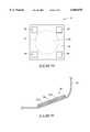
- a conveyor 30extends into liquid 20 at one end of vessel 12, and extends out of liquid 20 at another end of vessel 12. In the shown preferred embodiment, conveyor 30 enters liquid 20 through the portion of liquid upper surface 22 that is not coated with particulates 24.
- the exemplary shown conveyor 30is a belt, but it is to be understood that the invention encompasses other embodiments (not shown) wherein conveyor 30 comprises other conveying structures such as, for example, moving cables or chains.
- Belt 30is a preferably continuous belt attached to a mechanism (not shown) which pulls belt 30 through liquid 20 in the direction indicated by the arrows at the fragmentary ends of belt 30. Only a portion of the preferred continuous belt 30 is shown to increase clarity in the drawings.
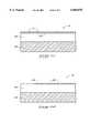
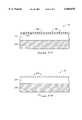
- Belt 30can comprise, for example, rubber, fabric and/or metal.
- belt 30can comprise a flexible polymer film, such as MylarTM.
- belt 30can comprise a thin metallic sheet, or a composite of assembly of materials comprising linked subsections.
Landscapes
- Engineering & Computer Science (AREA)
- Manufacturing & Machinery (AREA)
- Application Of Or Painting With Fluid Materials (AREA)
Abstract
Description
Claims (23)
Priority Applications (2)
| Application Number | Priority Date | Filing Date | Title |
|---|---|---|---|
| US09/146,731US6068878A (en) | 1998-09-03 | 1998-09-03 | Methods of forming layers of particulates on substrates |
| US09/396,388US6409835B1 (en) | 1998-09-03 | 1999-09-15 | Apparatuses for forming layers |
Applications Claiming Priority (1)
| Application Number | Priority Date | Filing Date | Title |
|---|---|---|---|
| US09/146,731US6068878A (en) | 1998-09-03 | 1998-09-03 | Methods of forming layers of particulates on substrates |
Related Child Applications (1)
| Application Number | Title | Priority Date | Filing Date |
|---|---|---|---|
| US09/396,388DivisionUS6409835B1 (en) | 1998-09-03 | 1999-09-15 | Apparatuses for forming layers |
Publications (1)
| Publication Number | Publication Date |
|---|---|
| US6068878Atrue US6068878A (en) | 2000-05-30 |
Family
ID=22518750
Family Applications (2)
| Application Number | Title | Priority Date | Filing Date |
|---|---|---|---|
| US09/146,731Expired - LifetimeUS6068878A (en) | 1998-09-03 | 1998-09-03 | Methods of forming layers of particulates on substrates |
| US09/396,388Expired - Fee RelatedUS6409835B1 (en) | 1998-09-03 | 1999-09-15 | Apparatuses for forming layers |
Family Applications After (1)
| Application Number | Title | Priority Date | Filing Date |
|---|---|---|---|
| US09/396,388Expired - Fee RelatedUS6409835B1 (en) | 1998-09-03 | 1999-09-15 | Apparatuses for forming layers |
Country Status (1)
| Country | Link |
|---|---|
| US (2) | US6068878A (en) |
Cited By (10)
| Publication number | Priority date | Publication date | Assignee | Title |
|---|---|---|---|---|
| US6258419B1 (en)* | 1999-09-02 | 2001-07-10 | Micron Technology, Inc. | Sonication of monolayer films |
| US6524874B1 (en)* | 1998-08-05 | 2003-02-25 | Micron Technology, Inc. | Methods of forming field emission tips using deposited particles as an etch mask |
| US6767439B2 (en)* | 1999-07-19 | 2004-07-27 | Young Park | High throughput thin film deposition and substrate handling method and apparatus for optical disk processing |
| US20060202392A1 (en)* | 2005-03-14 | 2006-09-14 | Agency For Science, Technology And Research | Tunable mask apparatus and process |
| ES2407582R1 (en)* | 2011-07-19 | 2013-10-11 | Univ Salamanca | DEVICE AND PROCEDURE FOR EFFECTING A LANGMUIR-BLODGETT COATING IN A TEXTILE MATERIAL |
| US20150044809A1 (en)* | 2012-02-10 | 2015-02-12 | Commissariat A L'energie Atomique Et Aux Ene Alt | Method for depositing particles onto a substrate, including a step of structuring a particle film on a liquid conveyor |
| US20150221483A1 (en)* | 2012-08-21 | 2015-08-06 | Regents Of The University Of Minnesota | Embedded mask patterning process for fabricating magnetic media and other structures |
| FR3020767A1 (en)* | 2014-05-08 | 2015-11-13 | Commissariat Energie Atomique | DEVICE FOR MAKING A DEPOSITION OF PARTICLES ON A SUBSTRATE AND DEPOSITION METHOD USING SUCH A DEVICE |
| US10347467B2 (en) | 2015-08-21 | 2019-07-09 | Regents Of The University Of Minnesota | Embedded mask patterning process for fabricating magnetic media and other structures |
| US20210109095A1 (en)* | 2019-10-15 | 2021-04-15 | 2Witech Solutions Llc | Process of preparing 3d array of particles and exemplary application thereof in sensor fabrication |
Citations (9)
| Publication number | Priority date | Publication date | Assignee | Title |
|---|---|---|---|---|
| US4093757A (en)* | 1976-02-11 | 1978-06-06 | Commissariat A L'energie Atomique | Method of forming and depositing monomolecular layers of amphiphilic molecules on a substrate |
| US4511604A (en)* | 1983-03-04 | 1985-04-16 | Commissariat A L'energie Atomique | Process and apparatus for producing alternate monomolecular layers |
| US4599969A (en)* | 1983-12-09 | 1986-07-15 | Commissariat A L'energie Atomique | Device for the formation and deposition on a substrate of monomolecular films |
| US4695480A (en)* | 1985-03-25 | 1987-09-22 | Compagnie Generale D'electricite | Method and apparatus for drawing a tape constituted by a support coated in a layer of semiconductor material, said tape being drawn from a liquid bath of said material |
| US4779562A (en)* | 1986-03-19 | 1988-10-25 | Fujitsu Limited | Apparatus for depositing mono-molecular layer |
| US4783348A (en)* | 1986-01-02 | 1988-11-08 | Daleco Research Development | Method and apparatus for depositing monomolecular layers on a substrate |
| US5286529A (en)* | 1988-02-24 | 1994-02-15 | Kabushiki Kaisha Toshiba | Method of forming an organic thin film |
| US5512326A (en)* | 1991-06-12 | 1996-04-30 | Canon Kabushiki Kaisha | Method and apparatus for forming monomolecular film or built-up monomolecular film |
| US5536982A (en)* | 1991-07-15 | 1996-07-16 | Matsushita Electric Industrial Co., Ltd. | Ultra thin polymer film electret |
Family Cites Families (1)
| Publication number | Priority date | Publication date | Assignee | Title |
|---|---|---|---|---|
| US4987851A (en)* | 1988-01-12 | 1991-01-29 | Kabushiki Kaisha Toshiba | Apparatus for forming organic thin film |
- 1998
- 1998-09-03USUS09/146,731patent/US6068878A/ennot_activeExpired - Lifetime
- 1999
- 1999-09-15USUS09/396,388patent/US6409835B1/ennot_activeExpired - Fee Related
Patent Citations (9)
| Publication number | Priority date | Publication date | Assignee | Title |
|---|---|---|---|---|
| US4093757A (en)* | 1976-02-11 | 1978-06-06 | Commissariat A L'energie Atomique | Method of forming and depositing monomolecular layers of amphiphilic molecules on a substrate |
| US4511604A (en)* | 1983-03-04 | 1985-04-16 | Commissariat A L'energie Atomique | Process and apparatus for producing alternate monomolecular layers |
| US4599969A (en)* | 1983-12-09 | 1986-07-15 | Commissariat A L'energie Atomique | Device for the formation and deposition on a substrate of monomolecular films |
| US4695480A (en)* | 1985-03-25 | 1987-09-22 | Compagnie Generale D'electricite | Method and apparatus for drawing a tape constituted by a support coated in a layer of semiconductor material, said tape being drawn from a liquid bath of said material |
| US4783348A (en)* | 1986-01-02 | 1988-11-08 | Daleco Research Development | Method and apparatus for depositing monomolecular layers on a substrate |
| US4779562A (en)* | 1986-03-19 | 1988-10-25 | Fujitsu Limited | Apparatus for depositing mono-molecular layer |
| US5286529A (en)* | 1988-02-24 | 1994-02-15 | Kabushiki Kaisha Toshiba | Method of forming an organic thin film |
| US5512326A (en)* | 1991-06-12 | 1996-04-30 | Canon Kabushiki Kaisha | Method and apparatus for forming monomolecular film or built-up monomolecular film |
| US5536982A (en)* | 1991-07-15 | 1996-07-16 | Matsushita Electric Industrial Co., Ltd. | Ultra thin polymer film electret |
Non-Patent Citations (2)
| Title |
|---|
| Product Information Brochure: "For tomorrow's world . . . KSV--Langmuir Instrument Specialist, KSV 5000", KSV Instruments Ltd., 7 pages undated. |
| Product Information Brochure: For tomorrow s world . . . KSV Langmuir Instrument Specialist, KSV 5000 , KSV Instruments Ltd., 7 pages undated.* |
Cited By (16)
| Publication number | Priority date | Publication date | Assignee | Title |
|---|---|---|---|---|
| US6524874B1 (en)* | 1998-08-05 | 2003-02-25 | Micron Technology, Inc. | Methods of forming field emission tips using deposited particles as an etch mask |
| US6767439B2 (en)* | 1999-07-19 | 2004-07-27 | Young Park | High throughput thin film deposition and substrate handling method and apparatus for optical disk processing |
| US6413319B2 (en)* | 1999-09-02 | 2002-07-02 | Micron Technology, Inc. | Sonication of monolayer films |
| US6540836B2 (en) | 1999-09-02 | 2003-04-01 | Micron Technology, Inc. | Sonication of monolayer films |
| US6258419B1 (en)* | 1999-09-02 | 2001-07-10 | Micron Technology, Inc. | Sonication of monolayer films |
| US20060202392A1 (en)* | 2005-03-14 | 2006-09-14 | Agency For Science, Technology And Research | Tunable mask apparatus and process |
| ES2407582R1 (en)* | 2011-07-19 | 2013-10-11 | Univ Salamanca | DEVICE AND PROCEDURE FOR EFFECTING A LANGMUIR-BLODGETT COATING IN A TEXTILE MATERIAL |
| US9358575B2 (en)* | 2012-02-10 | 2016-06-07 | Commissariat à l'énergie atomique et aux énergies alternatives | Method for depositing particles onto a substrate, including a step of structuring a particle film on a liquid conveyor |
| US20150044809A1 (en)* | 2012-02-10 | 2015-02-12 | Commissariat A L'energie Atomique Et Aux Ene Alt | Method for depositing particles onto a substrate, including a step of structuring a particle film on a liquid conveyor |
| US20150221483A1 (en)* | 2012-08-21 | 2015-08-06 | Regents Of The University Of Minnesota | Embedded mask patterning process for fabricating magnetic media and other structures |
| US9721767B2 (en)* | 2012-08-21 | 2017-08-01 | Regents Of The University Of Minnesota | Embedded mask patterning process for fabricating magnetic media and other structures |
| EP2942111A3 (en)* | 2014-05-08 | 2016-01-20 | Commissariat A L'energie Atomique Et Aux Energies Alternatives | Device for producing a deposit of particles on a substrate and depositing method using such a device |
| FR3020767A1 (en)* | 2014-05-08 | 2015-11-13 | Commissariat Energie Atomique | DEVICE FOR MAKING A DEPOSITION OF PARTICLES ON A SUBSTRATE AND DEPOSITION METHOD USING SUCH A DEVICE |
| US9839938B2 (en) | 2014-05-08 | 2017-12-12 | Commissariat A L'energie Atomique Et Aux Energies Alternatives | Device for carrying out a deposit of particles on a substrate and deposition method using such a device |
| US10347467B2 (en) | 2015-08-21 | 2019-07-09 | Regents Of The University Of Minnesota | Embedded mask patterning process for fabricating magnetic media and other structures |
| US20210109095A1 (en)* | 2019-10-15 | 2021-04-15 | 2Witech Solutions Llc | Process of preparing 3d array of particles and exemplary application thereof in sensor fabrication |
Also Published As
| Publication number | Publication date |
|---|---|
| US6409835B1 (en) | 2002-06-25 |
Similar Documents
| Publication | Publication Date | Title |
|---|---|---|
| US6068878A (en) | Methods of forming layers of particulates on substrates | |
| US8252164B2 (en) | Methods for nanowire alignment and deposition | |
| US8671959B2 (en) | Method and apparatus for cleaning a substrate using non-newtonian fluids | |
| US5339842A (en) | Methods and apparatus for cleaning objects | |
| US7892610B2 (en) | Method and system for printing aligned nanowires and other electrical devices | |
| Deshpande et al. | Observation of dynamic behavior of lithographically induced self-assembly of supramolecular periodic pillar arrays in a homopolymer film | |
| EP1118390B1 (en) | Coating method and coating system | |
| US8382466B2 (en) | Large area dissolvable template lithography | |
| JP2001042341A (en) | How to assemble a liquid crystal substrate | |
| JPH11350169A (en) | Wet etching apparatus and wet etching method | |
| JPH11271960A (en) | Evanescent light exposure mask, object to be exposed, and exposure apparatus using the same | |
| JP2004517718A (en) | Coating device and coating method | |
| WO2008091571A2 (en) | High-throughput apparatus for patterning flexible substrates and method of using the same | |
| CN107210193A (en) | Method and apparatus for cleaning and drying ic substrate | |
| CN115151516A (en) | Method and apparatus for treating a surface of a substrate and treated glass article | |
| WO2008060358A9 (en) | System and method for providing the capability of peeling thin polymer films from a substrate | |
| TW202141177A (en) | Method and device for detaching a stamp | |
| EP3281910B1 (en) | Method of forming micro-pipes on a substrate and a structure formed therewith | |
| KR20140122465A (en) | Adhesive pad for attaching and detaching wig and method of manufacturing the same | |
| JPH02185375A (en) | Method and device for manufacturing abrasive tape | |
| Volinsky et al. | Delaminated film buckling microchannels | |
| JPH03266432A (en) | Semiconductor substrate cleaning method and cleaning device | |
| JP3155289B2 (en) | Langmuir-Blodgett film forming method and film forming apparatus | |
| JPH04186719A (en) | Nozzle for dispenser | |
| WO2025022240A2 (en) | Filmless, chemically differentiated, nanostructured substrate on a rigid substrate |
Legal Events
| Date | Code | Title | Description |
|---|---|---|---|
| AS | Assignment | Owner name:MICRON TECHNOLOGY, INC., IDAHO Free format text:ASSIGNMENT OF ASSIGNORS INTEREST;ASSIGNOR:ALWAN, JAMES J.;REEL/FRAME:009446/0564 Effective date:19980902 | |
| STCF | Information on status: patent grant | Free format text:PATENTED CASE | |
| FEPP | Fee payment procedure | Free format text:PAYOR NUMBER ASSIGNED (ORIGINAL EVENT CODE: ASPN); ENTITY STATUS OF PATENT OWNER: LARGE ENTITY | |
| FPAY | Fee payment | Year of fee payment:4 | |
| FPAY | Fee payment | Year of fee payment:8 | |
| FPAY | Fee payment | Year of fee payment:12 | |
| AS | Assignment | Owner name:U.S. BANK NATIONAL ASSOCIATION, AS COLLATERAL AGENT, CALIFORNIA Free format text:SECURITY INTEREST;ASSIGNOR:MICRON TECHNOLOGY, INC.;REEL/FRAME:038669/0001 Effective date:20160426 Owner name:U.S. BANK NATIONAL ASSOCIATION, AS COLLATERAL AGEN Free format text:SECURITY INTEREST;ASSIGNOR:MICRON TECHNOLOGY, INC.;REEL/FRAME:038669/0001 Effective date:20160426 | |
| AS | Assignment | Owner name:MORGAN STANLEY SENIOR FUNDING, INC., AS COLLATERAL AGENT, MARYLAND Free format text:PATENT SECURITY AGREEMENT;ASSIGNOR:MICRON TECHNOLOGY, INC.;REEL/FRAME:038954/0001 Effective date:20160426 Owner name:MORGAN STANLEY SENIOR FUNDING, INC., AS COLLATERAL Free format text:PATENT SECURITY AGREEMENT;ASSIGNOR:MICRON TECHNOLOGY, INC.;REEL/FRAME:038954/0001 Effective date:20160426 | |
| AS | Assignment | Owner name:U.S. BANK NATIONAL ASSOCIATION, AS COLLATERAL AGENT, CALIFORNIA Free format text:CORRECTIVE ASSIGNMENT TO CORRECT THE REPLACE ERRONEOUSLY FILED PATENT #7358718 WITH THE CORRECT PATENT #7358178 PREVIOUSLY RECORDED ON REEL 038669 FRAME 0001. ASSIGNOR(S) HEREBY CONFIRMS THE SECURITY INTEREST;ASSIGNOR:MICRON TECHNOLOGY, INC.;REEL/FRAME:043079/0001 Effective date:20160426 Owner name:U.S. BANK NATIONAL ASSOCIATION, AS COLLATERAL AGEN Free format text:CORRECTIVE ASSIGNMENT TO CORRECT THE REPLACE ERRONEOUSLY FILED PATENT #7358718 WITH THE CORRECT PATENT #7358178 PREVIOUSLY RECORDED ON REEL 038669 FRAME 0001. ASSIGNOR(S) HEREBY CONFIRMS THE SECURITY INTEREST;ASSIGNOR:MICRON TECHNOLOGY, INC.;REEL/FRAME:043079/0001 Effective date:20160426 | |
| AS | Assignment | Owner name:JPMORGAN CHASE BANK, N.A., AS COLLATERAL AGENT, ILLINOIS Free format text:SECURITY INTEREST;ASSIGNORS:MICRON TECHNOLOGY, INC.;MICRON SEMICONDUCTOR PRODUCTS, INC.;REEL/FRAME:047540/0001 Effective date:20180703 Owner name:JPMORGAN CHASE BANK, N.A., AS COLLATERAL AGENT, IL Free format text:SECURITY INTEREST;ASSIGNORS:MICRON TECHNOLOGY, INC.;MICRON SEMICONDUCTOR PRODUCTS, INC.;REEL/FRAME:047540/0001 Effective date:20180703 | |
| AS | Assignment | Owner name:MICRON TECHNOLOGY, INC., IDAHO Free format text:RELEASE BY SECURED PARTY;ASSIGNOR:U.S. BANK NATIONAL ASSOCIATION, AS COLLATERAL AGENT;REEL/FRAME:047243/0001 Effective date:20180629 | |
| AS | Assignment | Owner name:MICRON TECHNOLOGY, INC., IDAHO Free format text:RELEASE BY SECURED PARTY;ASSIGNOR:MORGAN STANLEY SENIOR FUNDING, INC., AS COLLATERAL AGENT;REEL/FRAME:050937/0001 Effective date:20190731 | |
| AS | Assignment | Owner name:MICRON SEMICONDUCTOR PRODUCTS, INC., IDAHO Free format text:RELEASE BY SECURED PARTY;ASSIGNOR:JPMORGAN CHASE BANK, N.A., AS COLLATERAL AGENT;REEL/FRAME:051028/0001 Effective date:20190731 Owner name:MICRON TECHNOLOGY, INC., IDAHO Free format text:RELEASE BY SECURED PARTY;ASSIGNOR:JPMORGAN CHASE BANK, N.A., AS COLLATERAL AGENT;REEL/FRAME:051028/0001 Effective date:20190731 |