US6068621A - Articulating cannula - Google Patents
Articulating cannulaDownload PDFInfo
- Publication number
- US6068621A US6068621AUS09/196,942US19694298AUS6068621AUS 6068621 AUS6068621 AUS 6068621AUS 19694298 AUS19694298 AUS 19694298AUS 6068621 AUS6068621 AUS 6068621A
- Authority
- US
- United States
- Prior art keywords
- cannula
- slider
- proximal
- region
- distal region
- Prior art date
- Legal status (The legal status is an assumption and is not a legal conclusion. Google has not performed a legal analysis and makes no representation as to the accuracy of the status listed.)
- Expired - Lifetime
Links
- 239000008280bloodSubstances0.000claimsdescription23
- 210000004369bloodAnatomy0.000claimsdescription23
- 239000012530fluidSubstances0.000claimsdescription13
- 238000000034methodMethods0.000claimsdescription13
- 210000004204blood vesselAnatomy0.000claimsdescription10
- 238000006073displacement reactionMethods0.000abstractdescription2
- 238000003780insertionMethods0.000description17
- 230000037431insertionEffects0.000description17
- 230000007246mechanismEffects0.000description12
- 230000004913activationEffects0.000description7
- 239000000463materialSubstances0.000description6
- 238000001356surgical procedureMethods0.000description6
- 238000005452bendingMethods0.000description4
- 229910001220stainless steelInorganic materials0.000description4
- 230000001225therapeutic effectEffects0.000description4
- 210000003813thumbAnatomy0.000description4
- 230000017531blood circulationEffects0.000description3
- 239000010935stainless steelSubstances0.000description3
- 238000003466weldingMethods0.000description3
- 239000004698PolyethyleneSubstances0.000description2
- 239000000853adhesiveSubstances0.000description2
- 238000004026adhesive bondingMethods0.000description2
- 230000001070adhesive effectEffects0.000description2
- 238000004873anchoringMethods0.000description2
- 230000002612cardiopulmonary effectEffects0.000description2
- 238000004891communicationMethods0.000description2
- 210000001105femoral arteryAnatomy0.000description2
- 229920003023plasticPolymers0.000description2
- 239000004033plasticSubstances0.000description2
- -1polyethylenePolymers0.000description2
- 229920000573polyethylenePolymers0.000description2
- 239000004814polyurethaneSubstances0.000description2
- 229920000915polyvinyl chloridePolymers0.000description2
- 239000004800polyvinyl chlorideSubstances0.000description2
- 230000008569processEffects0.000description2
- 238000002560therapeutic procedureMethods0.000description2
- 238000011144upstream manufacturingMethods0.000description2
- 239000004593EpoxySubstances0.000description1
- 210000000709aortaAnatomy0.000description1
- 210000001367arteryAnatomy0.000description1
- 230000008901benefitEffects0.000description1
- 210000001715carotid arteryAnatomy0.000description1
- 230000035876healingEffects0.000description1
- 230000036541healthEffects0.000description1
- 238000002347injectionMethods0.000description1
- 239000007924injectionSubstances0.000description1
- 208000014674injuryDiseases0.000description1
- 229920000126latexPolymers0.000description1
- 239000002184metalSubstances0.000description1
- 230000010412perfusionEffects0.000description1
- 229920000515polycarbonatePolymers0.000description1
- 239000004417polycarbonateSubstances0.000description1
- 229920001296polysiloxanePolymers0.000description1
- 229920002635polyurethanePolymers0.000description1
- 229920003225polyurethane elastomerPolymers0.000description1
- 239000012858resilient materialSubstances0.000description1
- 229920002379silicone rubberPolymers0.000description1
- 230000008733traumaEffects0.000description1
- 230000000472traumatic effectEffects0.000description1
- 229920002554vinyl polymerPolymers0.000description1
- XLYOFNOQVPJJNP-UHFFFAOYSA-NwaterSubstancesOXLYOFNOQVPJJNP-UHFFFAOYSA-N0.000description1
Images


Classifications
- A—HUMAN NECESSITIES
- A61—MEDICAL OR VETERINARY SCIENCE; HYGIENE
- A61M—DEVICES FOR INTRODUCING MEDIA INTO, OR ONTO, THE BODY; DEVICES FOR TRANSDUCING BODY MEDIA OR FOR TAKING MEDIA FROM THE BODY; DEVICES FOR PRODUCING OR ENDING SLEEP OR STUPOR
- A61M25/00—Catheters; Hollow probes
- A61M25/0021—Catheters; Hollow probes characterised by the form of the tubing
- A61M25/0041—Catheters; Hollow probes characterised by the form of the tubing pre-formed, e.g. specially adapted to fit with the anatomy of body channels
- A—HUMAN NECESSITIES
- A61—MEDICAL OR VETERINARY SCIENCE; HYGIENE
- A61M—DEVICES FOR INTRODUCING MEDIA INTO, OR ONTO, THE BODY; DEVICES FOR TRANSDUCING BODY MEDIA OR FOR TAKING MEDIA FROM THE BODY; DEVICES FOR PRODUCING OR ENDING SLEEP OR STUPOR
- A61M2210/00—Anatomical parts of the body
- A61M2210/12—Blood circulatory system
- A61M2210/125—Heart
Definitions
- This inventionrelates to medical devices, and more particularly relates to an articulating cannula for use in cardiopulmonary bypass surgery, heart surgery, and other medical procedures.
- NasuU.S. Pat. No. 5,425,708 discloses a catheter or cannula with an L-shaped distal region. About the end of the distal region is positioned a vessel-occluding balloon. Such a device requires an insertion point adjacent to where the distal end of the catheter will be located.
- a surgeoncould insert a flexible cannula such as disclosed by Grinfeld et al., U.S. Pat. No. 5,312,344, into, for example, the femoral artery and guide the distal end to where therapy is desired. If necessary, balloons at the distal end are then inflated.
- This inventionprovides an articulating cannula for vessel occlusion, cardioplegia delivery, perfusion, aspiration, and other uses.
- the flexible distal end of the cannulais provided with a manipulator wire attached to an anchor.
- the manipulator wireextends up the rigid proximal shaft of the cannula and ends in a positionable slider or other tensioning mechanism.
- a toroidal balloonsurrounds the distal end of the cannula and is in fluid communication with a secondary lumen of the cannula. Inflation of the toroidal balloon with fluid injected through the secondary lumen occludes the vessel and prevents the cannula tip from injuring the vessel walls.
- a tertiary lumen which allows therapeutic fluids to be injected upstream of the artery occlusionmay be proximally located with respect to the toroidal balloon. Therapeutic fluids delivered through the tertiary lumen include fluids for cardioplegia.
- the articulating cannulacan include a blood filter device disposed within the primary lumen of the cannula.
- the blood filter devicemay comprise an insertion tube, an umbrella frame, an end plate, a mesh, and an adjustment device.
- the blood filter devicemay be disposed in a secondary lumen which opens proximally with respect to the distal end of the cannula.
- the blood filter devicemay comprise a shaft, an adjustable filter frame disposed at the distal end of the shaft, a mesh, and optionally, a cantilever beam.
- the articulating cannulacan include a diverter associated with the distal region of the cannula.
- the divertercan take a number of forms, including a "windsock" embodiment. The diverter will allow the surgeon to deflect blood flow from entering other vessels during procedures such as plaque removal.
- the articulation of the cannulamay be summarized as follows.
- the surgeonmay manipulate the slider distally so that the flexible distal end of the cannula is unbent. This allows the surgeon to insert the cannula at right angles to the vessel.
- the surgeonbegins to proximally position the slider (tensioning mechanism) so as to bend the distal tip of the cannula. This process of inserting and bending the cannula continues until the surgeon is satisfied with the positioning of the cannula's distal end. At this point, the distal end of the cannula lies substantially parallel to the vessel within the vessel's lumen.
- the surgeonmay then inflate the toroidal balloon in order to occlude the vessel.
- a filter meshmay be deployed within the vessel circumferentially about the distal portion of the cannula.
- the surgeonmay deploy a diverter in the vessel.
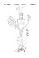
- FIG. 1ais a side elevational view partially broken away of the invention with a vessel-occluding toroidal balloon circumferentially disposed about the distal region.
- FIG. 1bis a perspective view of the distal region of the invention with an umbrella frame blood filter device circumferentially disposed about the distal region of the cannula.
- FIG. 1cis a side elevational view of the distal region of the invention in which a coil spring surrounds the distal region of the cannula.
- FIG. 1dis a cross-sectional view taken on line 1d--1d.
- FIG. 2ais an exploded cut-away view of the anchor and the tip cover connecting to the manipulator wire, manipulator wire tube and the slider.
- FIG. 2bis an enlarged view of the tip cover and the toroidal balloon taken along line 2b--2b of FIG. 2a.
- FIG. 2cis a cross-sectional view of the slider taken along line 2c--2c of FIG. 2a.
- FIG. 3ais a cross-sectional view of the slider and the proximal region of the cannula wherein the slider employs a camming mechanism in order to engage the proximal region of the cannula.
- FIG. 3bis a cross-sectional view of the slider and the proximal region of the cannula wherein the slider employs a bolt or screw which passes through a threaded hole and frictionally bears against the proximal region of the cannula.
- FIG. 4illustrates a cross section of the slider according to one embodiment of the invention.
- FIG. 5is a side elevational view according to one embodiment of the invention wherein the distal end of the cannula is associated with an umbrella frame blood filter device inserted in the main lumen of the cannula.
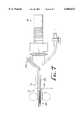
- FIG. 6ais a side elevational view of the invention according to one embodiment in which the distal portion of the cannula has been inserted into a vessel and articulated and in which a filter mesh device is inserted in a secondary lumen of the cannula.
- FIG. 6bis a cross sectional view of the blood filter device taken along line 6b--6b of FIG. 6a.
- FIG. 7is a side elevational view of the invention according to one embodiment in which the distal portion of the cannula is associated with a diverter in its compressed state.
- FIG. 8is a side elevational view of the invention according to one embodiment in which the distal portion of the invention is associated with a diverter deployed in the vessel.
- the present inventionis directed towards an articulating cannula for use in cardiopulmonary bypass surgery and other medical procedures.
- One embodiment of the articulating cannula according to the present inventionis shown in FIG. 1a.
- a flexible distal region 10 of the cannulamade of, for example, flexible polyvinyl chloride or polyethylene, is attached to a rigid proximal region 20.
- Proximal regionmay be constructed of rigid polyvinyl chloride, polyethylene, silicone, polycarbonate, or other suitable materials.
- Extending down both the proximal region 20 and distal region 10is primary lumen 8 ending in primary lumen port 5.
- Primary lumen 8extends proximally down the cannula and ends in input port 115 through which therapeutic fluids may be pumped.
- An anchor 30is affixed about the end of the distal region 10 of the cannula. Attached to the anchor 30 is the end of a manipulator wire 40. An anchor ball 45 at the end of manipulator wire 40 secures the manipulator wire 40 to the anchor 30.
- Manipulator wire 40in the embodiment shown, is disposed in a stainless steel hypodermic manipulator wire tube 48. Manipulator wire 40 is preferably constructed out of 316 L stainless steel wire. Alternatively a woven stainless steel cable or other suitable materials may be used. Manipulator wire 40 and tube 48 extend proximally from the distal region 10 of the cannula to the proximal region 20.
- the proximal end of manipulator wire 40is attached to a slider 50 that, in one embodiment, is circumferentially disposed about the handle region 60 of the cannula.
- Slider 50frictionally engages handle region 60 through a clamping mechanism and is positionable in a proximal and distal direction so as to bias manipulator wire 40 proximally or distally, thereby bending or straightening distal region 10.
- the slider's clamping mechanismfrictionally engages teeth 65 on handle region 60 by biasing radially movable balls 130 into grooves 68 on handle region 60.
- a coil spring 110may be integrated with the distal region 10 so as to prevent kinking of the lumen 8.
- a rigid or braid reinforced lumencould also be used to prevent kinking.
- coil spring 110would provide resiliency so as to keep distal region 10 and proximal region 20 in line with one another when slider 50 is positioned distally with respect to handle 60. Use of a plurality of separated rings instead of coil spring 110 would provide an equivalent protection against kinking.
- Circumferentially disposed about the distal region 10 of the cannulais a toroidal balloon 70 that is in fluid communication with a secondary lumen 75 of the cannula. Secondary lumen 75 proximally extends from toroidal balloon 70 to a proximal projection 76.
- Proximal projection 76may include a valve 77 operated by stopcock 78. Fluid, such as pressurized air or water distends toroidal balloon 70 by injection into port 79 of proximal projection 76.
- Toroidal balloon 70is preferably made out of a soft resilient material such as polyurethane, silicone, or latex rubber so as to expand and substantially or-completely occlude the desired vessel. Toroidal balloon's 70 size can be varied depending upon the size vessel being occluded.
- Proximal to toroidal balloon 70is a tertiary lumen port 80 connecting to tertiary lumen 85.
- Tertiary lumen 85proximally extends to a tertiary proximal projection 86.
- Therapeutic fluids pumped down inlet 88 of tertiary proximal projection 86provide fluids to vessel structures upstream of the toroidal balloon 70.
- Tertiary proximal projection 86may optionally be fitted with a valve and stopcock similar to those shown on the proximal projection 76.
- FIG. 1dThe relationship of the various lumens is illustrated in FIG. 1d. Although the secondary lumen 75 and tertiary lumen 85 are disposed on opposite sides of the cannula in the embodiment illustrated, their exact location and their relationship to the location of manipulator wire tube 48 and manipulator wire 40 is not critical to the overall functioning of the invention.
- the anchor 30may be associated with a conical tip cover 120 as illustrated in FIG. 2a. Lumen port 5 would then exit through tip cover 120 as illustrated in FIG. 2b. A pocket on anchor 30 receives anchor ball 45 of manipulator wire 40.
- manipulator wire 40is disposed in a stainless steel hypodermic manipulator wire tube 48 which extends from anchor 30 to slider 50. At its proximal end, manipulator wire is attached to slider 50 with a proximal anchor ball 135. Many other suitable attachment methods exist, including welding and gluing.
- slider 50can be slidably positioned proximally or distally on handle 60 in many ways.
- slider 50could be attached to cam 140.
- Cam 140is biased, using a spring 170 or other suitable means, so that flat region 142 of cam 140 abuts sidewall 66 of groove 68 on handle 60.
- curved surface 144 of cam 140causes cam 140 to rotate out of groove 68 on axis 143.
- cam 140is biased into grooves 68, as slider 50 is moved proximally to the adjacent proximal groove 68, cam 140 will rotate down into the adjacent proximal groove 68 on axis 143 so as to fix slider 50 to handle 60 in a new, proximally displaced position. This process can be repeated until slider 50 provides the desired proximal bias to manipulator wire 40, thereby bending distal region 10 of the cannula to a desired angle with respect to proximal region 20.
- a lever 146 rigidly attached to cam 140 at axis 143can be used to rotate cam 140 up out of groove 68 and maintain cam 140 out of grooves 68 as the slider is distally positioned, thereby straightening distal region 10 with respect to proximal region 20.
- FIG. 3bAn alternative clamp or clamping mechanism for positioning slider 50 to handle 60 is illustrated in FIG. 3b.
- Slider 50has a threaded hole 150 through which a bolt 145 is threaded.
- handle 60does not require teeth 65 and grooves 68.
- bolt 145frictionally bears against handle 60 and secures slider 50 in a fixed position with respect to handle 60.
- clamping mechanism of slider 50is constructed according to the invention of Lee, U.S. Pat. No. 4,893,810, the contents of which are incorporated herein by reference in its entirety.
- the invention of Leeis commercially available as the "Grip Fast"TM, manufactured by S.M.I., Inc.
- this embodiment of the clamping mechanismcomprises a collar body 160 with an axial flange 161. Circumferentially disposed about collar body 160 is collar sleeve 162 with a tension ring 163 having a tapered inner surface. The tapered inner surface bears against balls 130 that in turn are disposed in windows 165 on collar body 160.
- a spring 170biases collar body 160 with respect to sleeve 162 so that balls 164 are forced into windows 165 by the tapered inner surface of tension ring 163. This causes balls 130 to frictionally engage teeth 65 on handle 60 (illustrated in FIG. 1), thereby clamping slider 50 to handle 60.
- the health practitioner or surgeongrips the collar sleeve 162 of slider 50 and displaces it proximally with respect to handle 60.
- This proximal movementcompresses spring 170 so that tension ring 163 is displaced proximally with respect to balls 130.
- This proximal displacementallows the balls 130 to move up out of groove 68 on handle 60 so that slider 50 can be proximally displaced with respect to handle 60.
- manipulator wire 40is fixed to axial flange 161 of collar body 160, manipulator wire 40 proximally displaces anchor 30, thereby bending distal region 10 of the cannula.
- the surgeonfollows an analogous procedure. However, rather than displace the slider 50 proximally on handle 60 of the cannula, the surgeon now displaces the slider 50 distally on handle 60 of the cannula. This distal movement releases the tension on manipulator wire 40 so that distal region 10 of the cannula straightens with respect to proximal region 20 of the cannula.
- distal region 10may be combined with a blood filter device 90 disposed within the primary lumen 8 of the cannula as illustrated in FIG. 1b.
- the blood filter devicemay comprise an insertion tube 200, an activation tube 201, an umbrella frame 202, an end plate 204, a mesh 206, and an adjustment device 212 (illustrated in FIG. 5).
- the umbrella frame 20comprises a plurality of arms 208.
- the armsare sonically welded to a socket 210, which in turn is adhesive bonded to the insertion tube 200 which is dimensioned to fit within the main lumen 8 of the cannula without unnecessarily impeding blood flow.
- the socket 210may be connected to the insertion tube 200 by welding or epoxy.
- the insertion tube 200may be constructed with commercially available material such as polyvinyl, polyurethane, or other plastics.
- the arms 208 of the umbrella frame 202are made of plastic or thin gauge metal. Because of the flexibility of this material, the arms 208 bend without the need for extra parts such as hinges. This simplifies assembly and reduces the chance of misassembly.
- FIG. 5illustrates how the blood filter device 90 is actuated within the cannula.
- the insertion tube 200 and activation tube 201extend proximally from socket 210 in the main lumen 8 of the cannula to the blood filter device port 214.
- the activation tube 201extends from the blood filter device port 214 to the adjustment device 212 housed in blood filter device handle 216.
- the adjustment device 212is a linear actuation device, comprising a thumb switch 218 which is attached to a guide frame 220 which in turn is attached to the activation tube 201 via a bond joint.
- Thumb switch 218comprises a base 222 and a ratchet arm 224 that moves along a ratchet slot 226, locking in predetermined intervals in a manner known in the art. Sliding the thumb switch 218 proximally from the distal region 10 of the cannula retracts the activation tube 201, which in turn draws the end plate 204 towards the socket 210. This causes the arms 208 of the umbrella frame 202 to bend and the mesh 203 to open and enable the trapping of emboli in the blood. Sliding thumb switch 218 distally pushes the activation tube 201 in the direction of the mesh 204.
- the activation tube 201then pushes the end plate 204 away from socket 210, causing the arms 208 of the umbrella frame to straighten and mesh 204 to close.
- Further details of a blood filter device comprising an umbrella frameare described in Barbut et al, U.S. application Ser. No. 08/970,956, filed Nov. 14, 1997, the contents of which are incorporated by reference as if set forth in their entirety herein.
- the blood filter devicemay be located proximally from primary lumen port 5 and comprise an adjustable flexible frame rather than an umbrella frame. This is illustrated in FIG. 6a, wherein the distal region 10 of the cannula has been inserted into a vessel and articulated.
- the blood filter device 90is inserted in a secondary lumen 230 of the cannula which ends in a secondary lumen port 232. Extending proximally from the blood filter device 90 is a flexible insertion guide 234.
- blood filter device 90can be inserted into a vessel or withdrawn from the vessel into secondary lumen 230.
- blood filter device 90comprises a flexible frame 236, a cantilever beam 238, and a filter mesh 206.
- Cantilever beam 238is attached to frame 236 at its distal end and freely slides within flexible insertion guide 234 at its proximal end. Further details of a blood filter device incorporating a flexible frame 236 and a cantilever beam 238 are described in Ambrosio, U.S. application Ser. No. 09/070,660, filed Apr. 29, 1998, the contents of which are incorporated by reference as if set forth in their entirety herein.
- distal region 10can be combined with a diverter 100 as illustrated in FIG. 7 and FIG. 8.
- diverter 100allows the surgeon to prevent emboli from entering, for example, the carotid arteries during surgery.
- a divertermay take a number of forms, including a "snowshoe” and a “windsock” configuration.
- the diverter 100comprises a substantially cylindrical or conical wall 250 impermeable to emboli, compressibly disposed within an insertion cannula 260 which is disposed within the primary lumen 8 of the cannula.
- the diameter of insertion cannula 260is sized such that fluid flow within the primary lumen 8 of the cannula is relatively unimpeded.
- the clinicianguides the diverter insertion cannula, which is constructed from a suitably flexible material, down a secondary projection 290 of the cannula into the main lumen 8.
- a piston rod 270 having a piston 280 at its distal endpushes the proximal end of the diverter to drive it out of the main lumen of the cannula into the blood vessel.
- the diverteris self-expanding and its proximal end is anchored within the vessel with an anchoring mechanism 281.
- the anchoring mechanismmay comprise a sleeve adapted to frictionally engage the lumen of the vessel or any one of the following: one or more sutures, one or more clips, one or more hooks, or adhesive material.
Landscapes
- Health & Medical Sciences (AREA)
- Life Sciences & Earth Sciences (AREA)
- Biophysics (AREA)
- Pulmonology (AREA)
- Engineering & Computer Science (AREA)
- Anesthesiology (AREA)
- Biomedical Technology (AREA)
- Heart & Thoracic Surgery (AREA)
- Hematology (AREA)
- Animal Behavior & Ethology (AREA)
- General Health & Medical Sciences (AREA)
- Public Health (AREA)
- Veterinary Medicine (AREA)
- Surgical Instruments (AREA)
Abstract
Description
Claims (5)
Priority Applications (2)
| Application Number | Priority Date | Filing Date | Title |
|---|---|---|---|
| US09/196,942US6068621A (en) | 1998-11-20 | 1998-11-20 | Articulating cannula |
| US09/549,989US20020045915A1 (en) | 1998-11-20 | 2000-04-14 | Articulating cannula |
Applications Claiming Priority (1)
| Application Number | Priority Date | Filing Date | Title |
|---|---|---|---|
| US09/196,942US6068621A (en) | 1998-11-20 | 1998-11-20 | Articulating cannula |
Related Child Applications (1)
| Application Number | Title | Priority Date | Filing Date |
|---|---|---|---|
| US09/549,989ContinuationUS20020045915A1 (en) | 1998-11-20 | 2000-04-14 | Articulating cannula |
Publications (1)
| Publication Number | Publication Date |
|---|---|
| US6068621Atrue US6068621A (en) | 2000-05-30 |
Family
ID=22727388
Family Applications (2)
| Application Number | Title | Priority Date | Filing Date |
|---|---|---|---|
| US09/196,942Expired - LifetimeUS6068621A (en) | 1998-11-20 | 1998-11-20 | Articulating cannula |
| US09/549,989AbandonedUS20020045915A1 (en) | 1998-11-20 | 2000-04-14 | Articulating cannula |
Family Applications After (1)
| Application Number | Title | Priority Date | Filing Date |
|---|---|---|---|
| US09/549,989AbandonedUS20020045915A1 (en) | 1998-11-20 | 2000-04-14 | Articulating cannula |
Country Status (1)
| Country | Link |
|---|---|
| US (2) | US6068621A (en) |
Cited By (60)
| Publication number | Priority date | Publication date | Assignee | Title |
|---|---|---|---|---|
| US20020022860A1 (en)* | 2000-08-18 | 2002-02-21 | Borillo Thomas E. | Expandable implant devices for filtering blood flow from atrial appendages |
| US20020091408A1 (en)* | 1999-07-30 | 2002-07-11 | Sutton Gregg S. | Vascular filter system for carotid endarterectomy |
| US20020091409A1 (en)* | 1999-07-30 | 2002-07-11 | Sutton Gregg S. | Vascular filter system for cardiopulmonary bypass |
| US6508826B2 (en)* | 2001-04-30 | 2003-01-21 | Embol-X, Inc. | Cannula with flow diversion mechanism and methods of use |
| US20030023262A1 (en)* | 2001-07-18 | 2003-01-30 | Jeffrey Welch | Cardiac implant device tether system and method |
| US20030057156A1 (en)* | 2001-03-08 | 2003-03-27 | Dean Peterson | Atrial filter implants |
| US20030060844A1 (en)* | 1999-02-12 | 2003-03-27 | Thomas Borillo | Vascular filter system |
| US6551303B1 (en) | 1999-10-27 | 2003-04-22 | Atritech, Inc. | Barrier device for ostium of left atrial appendage |
| US6569182B1 (en)* | 1998-09-09 | 2003-05-27 | Embol-X, Inc. | Introducer/dilator with balloon protection and methods of use |
| US20030187461A1 (en)* | 1999-08-10 | 2003-10-02 | Chin Albert K. | Releasable guide and method for endoscopic cardiac lead placement |
| US20030187460A1 (en)* | 1999-08-10 | 2003-10-02 | Chin Albert K. | Methods and apparatus for endoscopic cardiac surgery |
| US6652556B1 (en) | 1999-10-27 | 2003-11-25 | Atritech, Inc. | Filter apparatus for ostium of left atrial appendage |
| US6652555B1 (en) | 1999-10-27 | 2003-11-25 | Atritech, Inc. | Barrier device for covering the ostium of left atrial appendage |
| US20040102804A1 (en)* | 1999-08-10 | 2004-05-27 | Chin Albert K. | Apparatus and methods for endoscopic surgical procedures |
| US20040111101A1 (en)* | 1999-08-10 | 2004-06-10 | Chin Albert K. | Endoscopic subxiphoid surgical procedures |
| US6755846B1 (en) | 1997-02-03 | 2004-06-29 | Angioguard, Inc. | Vascular filter |
| US20040216748A1 (en)* | 1999-08-10 | 2004-11-04 | Chin Albert K. | Apparatus and method for endoscopic encirclement of pulmonary veins for epicardial ablation |
| US20040230222A1 (en)* | 1999-11-08 | 2004-11-18 | Van Der Burg Erik J. | System for left atrial appendage occlusion |
| US20050004641A1 (en)* | 2001-06-04 | 2005-01-06 | Ramesh Pappu | Cardiac stimulating apparatus having a blood clot filter and atrial pacer |
| US20050004652A1 (en)* | 1998-11-06 | 2005-01-06 | Van Der Burg Eric J. | Method for left atrial appendage occlusion |
| US20050251091A1 (en)* | 2004-05-10 | 2005-11-10 | Usgi Medical Inc. | Apparatus and methods for transgastric tissue manipulation |
| US20060287574A1 (en)* | 1999-08-25 | 2006-12-21 | Chin Albert K | Longitudinal dilator |
| US7169164B2 (en) | 2000-09-21 | 2007-01-30 | Atritech, Inc. | Apparatus for implanting devices in atrial appendages |
| US20080015629A1 (en)* | 2002-01-14 | 2008-01-17 | Peter Thornton | Direct Access Atherectomy Devices and Methods of Use |
| US7398781B1 (en) | 1999-08-10 | 2008-07-15 | Maquet Cardiovascular, Llc | Method for subxiphoid endoscopic access |
| US7526342B2 (en) | 1999-08-10 | 2009-04-28 | Maquet Cardiovascular Llc | Apparatus for endoscopic cardiac mapping and lead placement |
| US7549983B2 (en) | 1999-09-20 | 2009-06-23 | Atritech, Inc. | Method of closing an opening in a wall of the heart |
| US20100069878A1 (en)* | 2007-04-10 | 2010-03-18 | The University Of Toledo | Intracavitary Radiation System |
| US7972359B2 (en) | 2005-09-16 | 2011-07-05 | Atritech, Inc. | Intracardiac cage and method of delivering same |
| US8043329B2 (en) | 1999-11-08 | 2011-10-25 | Atritech, Inc. | Method of implanting an adjustable occlusion device |
| US8685003B2 (en) | 2011-03-29 | 2014-04-01 | Covidien Lp | Dual cable triangulation mechanism |
| US8845517B2 (en) | 2011-06-27 | 2014-09-30 | Covidien Lp | Triangulation mechanism for a minimally invasive surgical device |
| US9017314B2 (en) | 2011-06-01 | 2015-04-28 | Covidien Lp | Surgical articulation assembly |
| US9204869B2 (en) | 2012-01-09 | 2015-12-08 | Covidien Lp | Articulation control mechanisms |
| US9271701B2 (en) | 2012-01-09 | 2016-03-01 | Covidien Lp | Surgical articulation assembly |
| US9381010B2 (en) | 2011-06-27 | 2016-07-05 | Covidien Lp | Surgical instrument with adapter for facilitating multi-direction end effector articulation |
| US9470297B2 (en) | 2012-12-19 | 2016-10-18 | Covidien Lp | Lower anterior resection 90 degree instrument |
| US9474516B2 (en) | 2011-11-08 | 2016-10-25 | Boston Scientific Scimed, Inc. | Handle assembly for a left atrial appendage occlusion device |
| US9730701B2 (en) | 2014-01-16 | 2017-08-15 | Boston Scientific Scimed, Inc. | Retrieval wire centering device |
| US9883936B2 (en) | 2002-01-25 | 2018-02-06 | Boston Scientific Scimed, Inc | Atrial appendage blood filtration systems |
| US10426976B1 (en) | 2016-06-22 | 2019-10-01 | The University Of Toledo | Nitinol organ positioner to prevent damage to healthy tissue during radiation oncology treatments |
| US10667896B2 (en) | 2015-11-13 | 2020-06-02 | Cardiac Pacemakers, Inc. | Bioabsorbable left atrial appendage closure with endothelialization promoting surface |
| US10952741B2 (en) | 2017-12-18 | 2021-03-23 | Boston Scientific Scimed, Inc. | Occlusive device with expandable member |
| US11123079B2 (en) | 2018-06-08 | 2021-09-21 | Boston Scientific Scimed, Inc. | Occlusive device with actuatable fixation members |
| US11241239B2 (en) | 2018-05-15 | 2022-02-08 | Boston Scientific Scimed, Inc. | Occlusive medical device with charged polymer coating |
| US11331104B2 (en) | 2018-05-02 | 2022-05-17 | Boston Scientific Scimed, Inc. | Occlusive sealing sensor system |
| US11382635B2 (en) | 2018-07-06 | 2022-07-12 | Boston Scientific Scimed, Inc. | Occlusive medical device |
| US11413048B2 (en) | 2018-01-19 | 2022-08-16 | Boston Scientific Scimed, Inc. | Occlusive medical device with delivery system |
| US11432809B2 (en) | 2017-04-27 | 2022-09-06 | Boston Scientific Scimed, Inc. | Occlusive medical device with fabric retention barb |
| US11540838B2 (en) | 2019-08-30 | 2023-01-03 | Boston Scientific Scimed, Inc. | Left atrial appendage implant with sealing disk |
| US11596533B2 (en) | 2018-08-21 | 2023-03-07 | Boston Scientific Scimed, Inc. | Projecting member with barb for cardiovascular devices |
| US11672541B2 (en) | 2018-06-08 | 2023-06-13 | Boston Scientific Scimed, Inc. | Medical device with occlusive member |
| US11903589B2 (en) | 2020-03-24 | 2024-02-20 | Boston Scientific Scimed, Inc. | Medical system for treating a left atrial appendage |
| US11944314B2 (en) | 2019-07-17 | 2024-04-02 | Boston Scientific Scimed, Inc. | Left atrial appendage implant with continuous covering |
| US12023036B2 (en) | 2020-12-18 | 2024-07-02 | Boston Scientific Scimed, Inc. | Occlusive medical device having sensing capabilities |
| US12318092B2 (en) | 2021-06-22 | 2025-06-03 | Boston Scientific Scimed, Inc. | Left atrial appendage implant |
| US12329500B2 (en) | 2020-11-30 | 2025-06-17 | Boston Scientific Scimed, Inc. | Implantable passive mean pressure sensor |
| US12349918B2 (en) | 2021-09-08 | 2025-07-08 | Boston Scientific Scimed, Inc. | Multi-sharpness split top soft tissue anchors |
| US12383278B2 (en) | 2021-07-08 | 2025-08-12 | Boston Scientific Scimed, Inc. | Left atrial appendage closure device |
| US12383201B2 (en) | 2021-02-03 | 2025-08-12 | Boston Scientific Scimed, Inc. | Medical system for treating a left atrial appendage |
Families Citing this family (24)
| Publication number | Priority date | Publication date | Assignee | Title |
|---|---|---|---|---|
| WO2006042114A1 (en) | 2004-10-06 | 2006-04-20 | Cook, Inc. | Emboli capturing device having a coil and method for capturing emboli |
| US20060184194A1 (en)* | 2005-02-15 | 2006-08-17 | Cook Incorporated | Embolic protection device |
| US8945169B2 (en) | 2005-03-15 | 2015-02-03 | Cook Medical Technologies Llc | Embolic protection device |
| US8221446B2 (en) | 2005-03-15 | 2012-07-17 | Cook Medical Technologies | Embolic protection device |
| US7850708B2 (en) | 2005-06-20 | 2010-12-14 | Cook Incorporated | Embolic protection device having a reticulated body with staggered struts |
| US8109962B2 (en) | 2005-06-20 | 2012-02-07 | Cook Medical Technologies Llc | Retrievable device having a reticulation portion with staggered struts |
| US7766934B2 (en) | 2005-07-12 | 2010-08-03 | Cook Incorporated | Embolic protection device with an integral basket and bag |
| US7771452B2 (en) | 2005-07-12 | 2010-08-10 | Cook Incorporated | Embolic protection device with a filter bag that disengages from a basket |
| US8187298B2 (en) | 2005-08-04 | 2012-05-29 | Cook Medical Technologies Llc | Embolic protection device having inflatable frame |
| US8377092B2 (en) | 2005-09-16 | 2013-02-19 | Cook Medical Technologies Llc | Embolic protection device |
| US8632562B2 (en) | 2005-10-03 | 2014-01-21 | Cook Medical Technologies Llc | Embolic protection device |
| US8182508B2 (en)* | 2005-10-04 | 2012-05-22 | Cook Medical Technologies Llc | Embolic protection device |
| US8252017B2 (en) | 2005-10-18 | 2012-08-28 | Cook Medical Technologies Llc | Invertible filter for embolic protection |
| US8216269B2 (en) | 2005-11-02 | 2012-07-10 | Cook Medical Technologies Llc | Embolic protection device having reduced profile |
| US8152831B2 (en) | 2005-11-17 | 2012-04-10 | Cook Medical Technologies Llc | Foam embolic protection device |
| US20080071307A1 (en) | 2006-09-19 | 2008-03-20 | Cook Incorporated | Apparatus and methods for in situ embolic protection |
| US9901434B2 (en) | 2007-02-27 | 2018-02-27 | Cook Medical Technologies Llc | Embolic protection device including a Z-stent waist band |
| US8252018B2 (en) | 2007-09-14 | 2012-08-28 | Cook Medical Technologies Llc | Helical embolic protection device |
| US9138307B2 (en) | 2007-09-14 | 2015-09-22 | Cook Medical Technologies Llc | Expandable device for treatment of a stricture in a body vessel |
| US8419748B2 (en) | 2007-09-14 | 2013-04-16 | Cook Medical Technologies Llc | Helical thrombus removal device |
| US8388644B2 (en) | 2008-12-29 | 2013-03-05 | Cook Medical Technologies Llc | Embolic protection device and method of use |
| US9808317B2 (en) | 2012-01-09 | 2017-11-07 | Covidien Lp | Pneumatic system for deployment of articulating arms for an access port |
| US9414752B2 (en) | 2012-11-09 | 2016-08-16 | Elwha Llc | Embolism deflector |
| WO2023278591A1 (en) | 2021-06-29 | 2023-01-05 | Resnent, Llc | Articulating cannula with endoscope attachment |
Citations (25)
| Publication number | Priority date | Publication date | Assignee | Title |
|---|---|---|---|---|
| US3896816A (en)* | 1971-05-03 | 1975-07-29 | Martin Mattler | Disposable catheter |
| US4522195A (en)* | 1981-05-25 | 1985-06-11 | Peter Schiff | Apparatus for left heart assist |
| US4719924A (en)* | 1986-09-09 | 1988-01-19 | C. R. Bard, Inc. | Small diameter steerable guidewire with adjustable tip |
| US4886067A (en)* | 1989-01-03 | 1989-12-12 | C. R. Bard, Inc. | Steerable guidewire with soft adjustable tip |
| US4893810A (en)* | 1986-07-21 | 1990-01-16 | Lee Scott H | Quick release collar |
| US4898577A (en)* | 1988-09-28 | 1990-02-06 | Advanced Cardiovascular Systems, Inc. | Guiding cathether with controllable distal tip |
| US4917102A (en)* | 1988-09-14 | 1990-04-17 | Advanced Cardiovascular Systems, Inc. | Guidewire assembly with steerable adjustable tip |
| US5030204A (en)* | 1988-09-28 | 1991-07-09 | Advanced Cardiovascular Systems, Inc. | Guiding catheter with controllable distal tip |
| US5312344A (en)* | 1991-02-25 | 1994-05-17 | Grinfeld Roberto R | Arterial perfusion cannula for extracorporeal circulation and other uses |
| US5425708A (en)* | 1991-12-13 | 1995-06-20 | Nissho Corporation | Catheter with an aorta-occluding balloon |
| US5487757A (en)* | 1993-07-20 | 1996-01-30 | Medtronic Cardiorhythm | Multicurve deflectable catheter |
| US5520222A (en)* | 1989-10-13 | 1996-05-28 | Kabushiki Kaisha Machida Seisakusho | Bending device |
| US5527279A (en)* | 1992-12-01 | 1996-06-18 | Cardiac Pathways Corporation | Control mechanism and system and method for steering distal extremity of a flexible elongate member |
| US5531677A (en)* | 1992-08-12 | 1996-07-02 | Vidamed, Inc. | Steerable medical probe with stylets |
| US5632734A (en)* | 1995-10-10 | 1997-05-27 | Guided Medical Systems, Inc. | Catheter shape control by collapsible inner tubular member |
| US5682906A (en)* | 1993-02-22 | 1997-11-04 | Heartport, Inc. | Methods of performing intracardiac procedures on an arrested heart |
| US5695519A (en)* | 1995-11-30 | 1997-12-09 | American Biomed, Inc. | Percutaneous filter for carotid angioplasty |
| US5700269A (en)* | 1995-06-06 | 1997-12-23 | Corvita Corporation | Endoluminal prosthesis deployment device for use with prostheses of variable length and having retraction ability |
| US5769816A (en)* | 1995-11-07 | 1998-06-23 | Embol-X, Inc. | Cannula with associated filter |
| US5776115A (en)* | 1996-01-17 | 1998-07-07 | Becton Dickinson And Company | Catheter having a gear-shaped lumen to avert the elimination of fluid flow therein |
| US5792094A (en)* | 1991-07-16 | 1998-08-11 | Heartport, Inc. | Method of delivering cardioplegic fluid to a patient's heart |
| US5800457A (en)* | 1997-03-05 | 1998-09-01 | Gelbfish; Gary A. | Intravascular filter and associated methodology |
| US5846260A (en)* | 1997-05-08 | 1998-12-08 | Embol-X, Inc. | Cannula with a modular filter for filtering embolic material |
| US5853400A (en)* | 1994-11-10 | 1998-12-29 | Target Therapeutics, Inc. | High performance spiral-wound catheter |
| US5865802A (en)* | 1988-07-22 | 1999-02-02 | Yoon; Inbae | Expandable multifunctional instruments for creating spaces at obstructed sites endoscopically |
- 1998
- 1998-11-20USUS09/196,942patent/US6068621A/ennot_activeExpired - Lifetime
- 2000
- 2000-04-14USUS09/549,989patent/US20020045915A1/ennot_activeAbandoned
Patent Citations (25)
| Publication number | Priority date | Publication date | Assignee | Title |
|---|---|---|---|---|
| US3896816A (en)* | 1971-05-03 | 1975-07-29 | Martin Mattler | Disposable catheter |
| US4522195A (en)* | 1981-05-25 | 1985-06-11 | Peter Schiff | Apparatus for left heart assist |
| US4893810A (en)* | 1986-07-21 | 1990-01-16 | Lee Scott H | Quick release collar |
| US4719924A (en)* | 1986-09-09 | 1988-01-19 | C. R. Bard, Inc. | Small diameter steerable guidewire with adjustable tip |
| US5865802A (en)* | 1988-07-22 | 1999-02-02 | Yoon; Inbae | Expandable multifunctional instruments for creating spaces at obstructed sites endoscopically |
| US4917102A (en)* | 1988-09-14 | 1990-04-17 | Advanced Cardiovascular Systems, Inc. | Guidewire assembly with steerable adjustable tip |
| US4898577A (en)* | 1988-09-28 | 1990-02-06 | Advanced Cardiovascular Systems, Inc. | Guiding cathether with controllable distal tip |
| US5030204A (en)* | 1988-09-28 | 1991-07-09 | Advanced Cardiovascular Systems, Inc. | Guiding catheter with controllable distal tip |
| US4886067A (en)* | 1989-01-03 | 1989-12-12 | C. R. Bard, Inc. | Steerable guidewire with soft adjustable tip |
| US5520222A (en)* | 1989-10-13 | 1996-05-28 | Kabushiki Kaisha Machida Seisakusho | Bending device |
| US5312344A (en)* | 1991-02-25 | 1994-05-17 | Grinfeld Roberto R | Arterial perfusion cannula for extracorporeal circulation and other uses |
| US5792094A (en)* | 1991-07-16 | 1998-08-11 | Heartport, Inc. | Method of delivering cardioplegic fluid to a patient's heart |
| US5425708A (en)* | 1991-12-13 | 1995-06-20 | Nissho Corporation | Catheter with an aorta-occluding balloon |
| US5531677A (en)* | 1992-08-12 | 1996-07-02 | Vidamed, Inc. | Steerable medical probe with stylets |
| US5527279A (en)* | 1992-12-01 | 1996-06-18 | Cardiac Pathways Corporation | Control mechanism and system and method for steering distal extremity of a flexible elongate member |
| US5682906A (en)* | 1993-02-22 | 1997-11-04 | Heartport, Inc. | Methods of performing intracardiac procedures on an arrested heart |
| US5487757A (en)* | 1993-07-20 | 1996-01-30 | Medtronic Cardiorhythm | Multicurve deflectable catheter |
| US5853400A (en)* | 1994-11-10 | 1998-12-29 | Target Therapeutics, Inc. | High performance spiral-wound catheter |
| US5700269A (en)* | 1995-06-06 | 1997-12-23 | Corvita Corporation | Endoluminal prosthesis deployment device for use with prostheses of variable length and having retraction ability |
| US5632734A (en)* | 1995-10-10 | 1997-05-27 | Guided Medical Systems, Inc. | Catheter shape control by collapsible inner tubular member |
| US5769816A (en)* | 1995-11-07 | 1998-06-23 | Embol-X, Inc. | Cannula with associated filter |
| US5695519A (en)* | 1995-11-30 | 1997-12-09 | American Biomed, Inc. | Percutaneous filter for carotid angioplasty |
| US5776115A (en)* | 1996-01-17 | 1998-07-07 | Becton Dickinson And Company | Catheter having a gear-shaped lumen to avert the elimination of fluid flow therein |
| US5800457A (en)* | 1997-03-05 | 1998-09-01 | Gelbfish; Gary A. | Intravascular filter and associated methodology |
| US5846260A (en)* | 1997-05-08 | 1998-12-08 | Embol-X, Inc. | Cannula with a modular filter for filtering embolic material |
Cited By (114)
| Publication number | Priority date | Publication date | Assignee | Title |
|---|---|---|---|---|
| US6755846B1 (en) | 1997-02-03 | 2004-06-29 | Angioguard, Inc. | Vascular filter |
| US6569182B1 (en)* | 1998-09-09 | 2003-05-27 | Embol-X, Inc. | Introducer/dilator with balloon protection and methods of use |
| US6689152B2 (en) | 1998-09-09 | 2004-02-10 | Edwards Lifesciences Corp. | Introducer/dilator with balloon protection and methods of use |
| US8523897B2 (en) | 1998-11-06 | 2013-09-03 | Atritech, Inc. | Device for left atrial appendage occlusion |
| US8535343B2 (en) | 1998-11-06 | 2013-09-17 | Atritech, Inc. | Method for left atrial appendage occlusion |
| US20050004652A1 (en)* | 1998-11-06 | 2005-01-06 | Van Der Burg Eric J. | Method for left atrial appendage occlusion |
| US7722641B2 (en) | 1998-11-06 | 2010-05-25 | Atritech, Inc. | Filter mesh for preventing passage of embolic material form an atrial appendage |
| US20050203568A1 (en)* | 1998-11-06 | 2005-09-15 | Burg Erik J.V. | Filter mesh for preventing passage of embolic material form an atrial appendage |
| US20030060844A1 (en)* | 1999-02-12 | 2003-03-27 | Thomas Borillo | Vascular filter system |
| US7399308B2 (en) | 1999-02-12 | 2008-07-15 | Cordis Corporation | Vascular filter system |
| US7229463B2 (en) | 1999-07-30 | 2007-06-12 | Angioguard, Inc. | Vascular filter system for cardiopulmonary bypass |
| US7229462B2 (en) | 1999-07-30 | 2007-06-12 | Angioguard, Inc. | Vascular filter system for carotid endarterectomy |
| US20020091409A1 (en)* | 1999-07-30 | 2002-07-11 | Sutton Gregg S. | Vascular filter system for cardiopulmonary bypass |
| US20020091408A1 (en)* | 1999-07-30 | 2002-07-11 | Sutton Gregg S. | Vascular filter system for carotid endarterectomy |
| US20040111101A1 (en)* | 1999-08-10 | 2004-06-10 | Chin Albert K. | Endoscopic subxiphoid surgical procedures |
| US20040216748A1 (en)* | 1999-08-10 | 2004-11-04 | Chin Albert K. | Apparatus and method for endoscopic encirclement of pulmonary veins for epicardial ablation |
| US7398781B1 (en) | 1999-08-10 | 2008-07-15 | Maquet Cardiovascular, Llc | Method for subxiphoid endoscopic access |
| US7264587B2 (en) | 1999-08-10 | 2007-09-04 | Origin Medsystems, Inc. | Endoscopic subxiphoid surgical procedures |
| US7526342B2 (en) | 1999-08-10 | 2009-04-28 | Maquet Cardiovascular Llc | Apparatus for endoscopic cardiac mapping and lead placement |
| US20040102804A1 (en)* | 1999-08-10 | 2004-05-27 | Chin Albert K. | Apparatus and methods for endoscopic surgical procedures |
| US7597698B2 (en) | 1999-08-10 | 2009-10-06 | Maquet Cardiovascular Llc | Apparatus and method for endoscopic encirclement of pulmonary veins for epicardial ablation |
| US20030187460A1 (en)* | 1999-08-10 | 2003-10-02 | Chin Albert K. | Methods and apparatus for endoscopic cardiac surgery |
| US20030187461A1 (en)* | 1999-08-10 | 2003-10-02 | Chin Albert K. | Releasable guide and method for endoscopic cardiac lead placement |
| US20060287574A1 (en)* | 1999-08-25 | 2006-12-21 | Chin Albert K | Longitudinal dilator |
| US7549983B2 (en) | 1999-09-20 | 2009-06-23 | Atritech, Inc. | Method of closing an opening in a wall of the heart |
| US9421004B2 (en) | 1999-09-20 | 2016-08-23 | Atritech Inc. | Method of closing an opening in a wall of the heart |
| US7727189B2 (en) | 1999-10-27 | 2010-06-01 | Atritech, Inc. | Filter apparatus for ostium of left atrial appendage |
| US6652555B1 (en) | 1999-10-27 | 2003-11-25 | Atritech, Inc. | Barrier device for covering the ostium of left atrial appendage |
| US20040127935A1 (en)* | 1999-10-27 | 2004-07-01 | Atritech, Inc. | Filter apparatus for ostium of left atrial appendage |
| US6551303B1 (en) | 1999-10-27 | 2003-04-22 | Atritech, Inc. | Barrier device for ostium of left atrial appendage |
| US6949113B2 (en) | 1999-10-27 | 2005-09-27 | Atritech, Inc. | Barrier device for ostium of left atrial appendage |
| US9132000B2 (en) | 1999-10-27 | 2015-09-15 | Atritech Inc. | Filter apparatus for ostium of left atrial appendage |
| US6652556B1 (en) | 1999-10-27 | 2003-11-25 | Atritech, Inc. | Filter apparatus for ostium of left atrial appendage |
| US20050049573A1 (en)* | 1999-10-27 | 2005-03-03 | Atritech, Inc. | Barrier device for ostium of left atrial appendage |
| US8685055B2 (en) | 1999-10-27 | 2014-04-01 | Atritech, Inc. | Filter apparatus for ostium of left atrial appendage |
| US6730108B2 (en) | 1999-10-27 | 2004-05-04 | Atritech, Inc. | Barrier device for ostium of left atrial appendage |
| US8221445B2 (en) | 1999-10-27 | 2012-07-17 | Atritech, Inc. | Barrier device for ostium of left atrial appendage |
| US10893926B2 (en) | 1999-10-27 | 2021-01-19 | Atritech, Inc. | Filter apparatus for ostium of left atrial appendage |
| US20040049210A1 (en)* | 1999-10-27 | 2004-03-11 | Vantassel Robert A. | Filter apparatus for ostium of left atrial appendage |
| US6689150B1 (en) | 1999-10-27 | 2004-02-10 | Atritech, Inc. | Filter apparatus for ostium of left atrial appendage |
| US8663273B2 (en) | 1999-11-08 | 2014-03-04 | Atritech, Inc. | Method of implanting an adjustable occlusion device |
| US9943299B2 (en) | 1999-11-08 | 2018-04-17 | Atritech, Inc. | Method of implanting an adjustable occlusion device |
| US8043329B2 (en) | 1999-11-08 | 2011-10-25 | Atritech, Inc. | Method of implanting an adjustable occlusion device |
| US20040230222A1 (en)* | 1999-11-08 | 2004-11-18 | Van Der Burg Erik J. | System for left atrial appendage occlusion |
| US20020022860A1 (en)* | 2000-08-18 | 2002-02-21 | Borillo Thomas E. | Expandable implant devices for filtering blood flow from atrial appendages |
| US7169164B2 (en) | 2000-09-21 | 2007-01-30 | Atritech, Inc. | Apparatus for implanting devices in atrial appendages |
| US20030057156A1 (en)* | 2001-03-08 | 2003-03-27 | Dean Peterson | Atrial filter implants |
| EP1383569A4 (en)* | 2001-04-30 | 2007-02-07 | Edwards Lifesciences Corp | Cannula with flow diversion mechanism and methods of use |
| US20030105486A1 (en)* | 2001-04-30 | 2003-06-05 | Embol-X, Inc. | Cannula with flow diversion mechanism and methods of use |
| US6508826B2 (en)* | 2001-04-30 | 2003-01-21 | Embol-X, Inc. | Cannula with flow diversion mechanism and methods of use |
| US20050004641A1 (en)* | 2001-06-04 | 2005-01-06 | Ramesh Pappu | Cardiac stimulating apparatus having a blood clot filter and atrial pacer |
| US6941169B2 (en) | 2001-06-04 | 2005-09-06 | Albert Einstein Healthcare Network | Cardiac stimulating apparatus having a blood clot filter and atrial pacer |
| US7011671B2 (en) | 2001-07-18 | 2006-03-14 | Atritech, Inc. | Cardiac implant device tether system and method |
| US20030023262A1 (en)* | 2001-07-18 | 2003-01-30 | Jeffrey Welch | Cardiac implant device tether system and method |
| US20120265225A1 (en)* | 2002-01-14 | 2012-10-18 | Edwards Lifesciences Corporation | Direct access atherectomy devices and methods of use |
| US8206403B2 (en)* | 2002-01-14 | 2012-06-26 | Edwards Lifesciences Corporation | Direct access atherectomy devices and methods of use |
| US8551112B2 (en)* | 2002-01-14 | 2013-10-08 | Edwards Lifesciences Corporation | Direct access atherectomy devices and methods of use |
| US20080015629A1 (en)* | 2002-01-14 | 2008-01-17 | Peter Thornton | Direct Access Atherectomy Devices and Methods of Use |
| US10751158B2 (en) | 2002-01-25 | 2020-08-25 | Atritech, Inc. | Atrial appendage blood filtration systems |
| US9883936B2 (en) | 2002-01-25 | 2018-02-06 | Boston Scientific Scimed, Inc | Atrial appendage blood filtration systems |
| EP1338250A1 (en)* | 2002-02-26 | 2003-08-27 | Cordis Corporation | Vascular filter system for cardiopulmonary bypass |
| AU2003200691B2 (en)* | 2002-02-26 | 2008-02-14 | Cardinal Health 529, Llc | Vascular filter system for cardiopulmonary bypass |
| US20050251091A1 (en)* | 2004-05-10 | 2005-11-10 | Usgi Medical Inc. | Apparatus and methods for transgastric tissue manipulation |
| US10143458B2 (en) | 2005-09-16 | 2018-12-04 | Atritech, Inc. | Intracardiac cage and method of delivering same |
| US7972359B2 (en) | 2005-09-16 | 2011-07-05 | Atritech, Inc. | Intracardiac cage and method of delivering same |
| US9445895B2 (en) | 2005-09-16 | 2016-09-20 | Atritech, Inc. | Intracardiac cage and method of delivering same |
| US20100069878A1 (en)* | 2007-04-10 | 2010-03-18 | The University Of Toledo | Intracavitary Radiation System |
| US8961383B2 (en)* | 2007-04-10 | 2015-02-24 | The University Of Toledo | Intracavitary radiation system |
| US8685003B2 (en) | 2011-03-29 | 2014-04-01 | Covidien Lp | Dual cable triangulation mechanism |
| US9017314B2 (en) | 2011-06-01 | 2015-04-28 | Covidien Lp | Surgical articulation assembly |
| US9381010B2 (en) | 2011-06-27 | 2016-07-05 | Covidien Lp | Surgical instrument with adapter for facilitating multi-direction end effector articulation |
| US9662003B2 (en) | 2011-06-27 | 2017-05-30 | Covidien Lp | Triangulation mechanism for a minimally invasive surgical device |
| US10413283B2 (en) | 2011-06-27 | 2019-09-17 | Covidien Lp | Surgical instrument with adapter for facilitating multi-direction end effector articulation |
| US8845517B2 (en) | 2011-06-27 | 2014-09-30 | Covidien Lp | Triangulation mechanism for a minimally invasive surgical device |
| US9968344B2 (en) | 2011-06-27 | 2018-05-15 | Covidien Lp | Surgical instrument with adapter for facilitating multi-direction end effector articulation |
| US9474516B2 (en) | 2011-11-08 | 2016-10-25 | Boston Scientific Scimed, Inc. | Handle assembly for a left atrial appendage occlusion device |
| US10130793B2 (en) | 2012-01-09 | 2018-11-20 | Covidien Lp | Surgical articulation assembly |
| US9271701B2 (en) | 2012-01-09 | 2016-03-01 | Covidien Lp | Surgical articulation assembly |
| US9901371B2 (en) | 2012-01-09 | 2018-02-27 | Covidien Lp | Articulation control mechanisms |
| US12251524B2 (en) | 2012-01-09 | 2025-03-18 | Covidien Lp | Surgical articulation assembly |
| US10905854B2 (en) | 2012-01-09 | 2021-02-02 | Covidien Lp | Surgical articulation assembly |
| US9204869B2 (en) | 2012-01-09 | 2015-12-08 | Covidien Lp | Articulation control mechanisms |
| US10456169B2 (en) | 2012-01-09 | 2019-10-29 | Covidien Lp | Articulation control mechanisms |
| US9470297B2 (en) | 2012-12-19 | 2016-10-18 | Covidien Lp | Lower anterior resection 90 degree instrument |
| US10024407B2 (en) | 2012-12-19 | 2018-07-17 | Covidien Lp | Lower anterior resection 90 degree instrument |
| US10463377B2 (en) | 2014-01-16 | 2019-11-05 | Boston Scientific Scimed, Inc. | Retrieval wire centering device |
| US11413047B2 (en) | 2014-01-16 | 2022-08-16 | Cardiac Pacemakers, Inc. | Occlusive medical implant |
| US9730701B2 (en) | 2014-01-16 | 2017-08-15 | Boston Scientific Scimed, Inc. | Retrieval wire centering device |
| US12193678B2 (en) | 2014-01-16 | 2025-01-14 | Boston Scientific Scimed, Inc. | Retrieval wire centering device |
| US10667896B2 (en) | 2015-11-13 | 2020-06-02 | Cardiac Pacemakers, Inc. | Bioabsorbable left atrial appendage closure with endothelialization promoting surface |
| US10426976B1 (en) | 2016-06-22 | 2019-10-01 | The University Of Toledo | Nitinol organ positioner to prevent damage to healthy tissue during radiation oncology treatments |
| US11432809B2 (en) | 2017-04-27 | 2022-09-06 | Boston Scientific Scimed, Inc. | Occlusive medical device with fabric retention barb |
| US12082797B2 (en) | 2017-04-27 | 2024-09-10 | Boston Scientific Scimed, Inc. | Occlusive medical device with fabric retention barb |
| US10952741B2 (en) | 2017-12-18 | 2021-03-23 | Boston Scientific Scimed, Inc. | Occlusive device with expandable member |
| US11925356B2 (en) | 2017-12-18 | 2024-03-12 | Boston Scientific Scimed, Inc. | Occlusive device with expandable member |
| US11413048B2 (en) | 2018-01-19 | 2022-08-16 | Boston Scientific Scimed, Inc. | Occlusive medical device with delivery system |
| US11331104B2 (en) | 2018-05-02 | 2022-05-17 | Boston Scientific Scimed, Inc. | Occlusive sealing sensor system |
| US11241239B2 (en) | 2018-05-15 | 2022-02-08 | Boston Scientific Scimed, Inc. | Occlusive medical device with charged polymer coating |
| US11672541B2 (en) | 2018-06-08 | 2023-06-13 | Boston Scientific Scimed, Inc. | Medical device with occlusive member |
| US11890018B2 (en) | 2018-06-08 | 2024-02-06 | Boston Scientific Scimed, Inc. | Occlusive device with actuatable fixation members |
| US11123079B2 (en) | 2018-06-08 | 2021-09-21 | Boston Scientific Scimed, Inc. | Occlusive device with actuatable fixation members |
| US11382635B2 (en) | 2018-07-06 | 2022-07-12 | Boston Scientific Scimed, Inc. | Occlusive medical device |
| US12232736B2 (en) | 2018-07-06 | 2025-02-25 | Boston Scientific Scimed, Inc | Occlusive medical device |
| US11596533B2 (en) | 2018-08-21 | 2023-03-07 | Boston Scientific Scimed, Inc. | Projecting member with barb for cardiovascular devices |
| US11944314B2 (en) | 2019-07-17 | 2024-04-02 | Boston Scientific Scimed, Inc. | Left atrial appendage implant with continuous covering |
| US11540838B2 (en) | 2019-08-30 | 2023-01-03 | Boston Scientific Scimed, Inc. | Left atrial appendage implant with sealing disk |
| US11903589B2 (en) | 2020-03-24 | 2024-02-20 | Boston Scientific Scimed, Inc. | Medical system for treating a left atrial appendage |
| US12329500B2 (en) | 2020-11-30 | 2025-06-17 | Boston Scientific Scimed, Inc. | Implantable passive mean pressure sensor |
| US12023036B2 (en) | 2020-12-18 | 2024-07-02 | Boston Scientific Scimed, Inc. | Occlusive medical device having sensing capabilities |
| US12383201B2 (en) | 2021-02-03 | 2025-08-12 | Boston Scientific Scimed, Inc. | Medical system for treating a left atrial appendage |
| US12318092B2 (en) | 2021-06-22 | 2025-06-03 | Boston Scientific Scimed, Inc. | Left atrial appendage implant |
| US12336715B2 (en) | 2021-06-22 | 2025-06-24 | Boston Scientific Scimed, Inc. | Left atrial appendage implant |
| US12383278B2 (en) | 2021-07-08 | 2025-08-12 | Boston Scientific Scimed, Inc. | Left atrial appendage closure device |
| US12349918B2 (en) | 2021-09-08 | 2025-07-08 | Boston Scientific Scimed, Inc. | Multi-sharpness split top soft tissue anchors |
Also Published As
| Publication number | Publication date |
|---|---|
| US20020045915A1 (en) | 2002-04-18 |
Similar Documents
| Publication | Publication Date | Title |
|---|---|---|
| US6068621A (en) | Articulating cannula | |
| US6350252B2 (en) | Methods and devices for occluding the ascending aorta and maintaining circulation of oxygenated blood in the patient when the patient's heart is arrested | |
| US6689098B2 (en) | Occlusion device | |
| US6149660A (en) | Method and apparatus for delivery of an appliance in a vessel | |
| JP3184735B2 (en) | Device for introducing a stent or stent-graft | |
| JP3601828B2 (en) | Device for deploying a radially expandable stent by mechanical linkage | |
| US4681110A (en) | Catheter arrangement having a blood vessel liner, and method of using it | |
| US8226670B2 (en) | Apparatus and method for connecting a conduit to a hollow organ | |
| CA2207211A1 (en) | Vascular dilatation device and method | |
| US20050033343A1 (en) | Catheter drive | |
| JPH02279148A (en) | Variable diametric sheath used in pathway in body | |
| CN116803358A (en) | Delivery system for artificial heart valves | |
| JP2003521996A (en) | Apparatus and method for delivery of endovascular prostheses | |
| EP2723435A1 (en) | Method and devices for flow occlusion during device exchanges | |
| KR101176154B1 (en) | Intraluminal Surgical Delivery System | |
| US20150342590A1 (en) | Inflatable laparoscopic retractor for atraumatic retraction in abdominal surgery | |
| WO2002000122A1 (en) | Device and method for performing vascular anastomosis | |
| CA2482697C (en) | Applier for a surgical device | |
| US6106531A (en) | Retrieval shuttle | |
| US20230088977A1 (en) | Guide catheter extension system for reverse controlled antegrade/retrograde tracking & thrombus removal procedures | |
| CN114302686B (en) | Medical device and method for closing an opening in tissue | |
| AU2021353035A9 (en) | Device for anchoring an introducer of a medical device into the human body | |
| WO2024097325A1 (en) | Embolic protection system and related methods | |
| US20100137884A1 (en) | Method and device for the controlled delivery and placement of securing elements in a body |
Legal Events
| Date | Code | Title | Description |
|---|---|---|---|
| AS | Assignment | Owner name:EMBOL-X, INC., CALIFORNIA Free format text:ASSIGNMENT OF ASSIGNORS INTEREST;ASSIGNORS:BALCETA, JOBERT;THORNTON, PETER;REEL/FRAME:009611/0175;SIGNING DATES FROM 19980928 TO 19981110 | |
| AS | Assignment | Owner name:MMC/GATX PARTNERSHIP NO.1, CALIFORNIA Free format text:SECURITY INTEREST;ASSIGNOR:EMBOL-X, INC.;REEL/FRAME:010152/0958 Effective date:19990923 Owner name:SILICON VALLEY BANK, CALIFORNIA Free format text:SECURITY INTEREST;ASSIGNOR:EMBOL-X, INC.;REEL/FRAME:010152/0958 Effective date:19990923 | |
| STCF | Information on status: patent grant | Free format text:PATENTED CASE | |
| AS | Assignment | Owner name:EMBOL-X, INC., CALIFORNIA Free format text:TERMINATION OF SECURITY INTEREST;ASSIGNORS:MMC/GATX PARNERSHIP NO. I;SILICON VALLEY BANK;REEL/FRAME:013029/0415 Effective date:20020809 | |
| FEPP | Fee payment procedure | Free format text:PAT HOLDER NO LONGER CLAIMS SMALL ENTITY STATUS, ENTITY STATUS SET TO UNDISCOUNTED (ORIGINAL EVENT CODE: STOL); ENTITY STATUS OF PATENT OWNER: LARGE ENTITY | |
| REFU | Refund | Free format text:REFUND - SURCHARGE, PETITION TO ACCEPT PYMT AFTER EXP, UNINTENTIONAL (ORIGINAL EVENT CODE: R2551); ENTITY STATUS OF PATENT OWNER: LARGE ENTITY | |
| AS | Assignment | Owner name:EDWARDS LIFESCIENCES CORPORATION, CALIFORNIA Free format text:ASSIGNMENT OF ASSIGNORS INTEREST;ASSIGNOR:EMBOL-X, INC.;REEL/FRAME:013998/0632 Effective date:20030417 | |
| FPAY | Fee payment | Year of fee payment:4 | |
| FPAY | Fee payment | Year of fee payment:8 | |
| FPAY | Fee payment | Year of fee payment:12 |