US6068608A - Method of using integral aortic arch infusion clamp - Google Patents
Method of using integral aortic arch infusion clampDownload PDFInfo
- Publication number
- US6068608A US6068608AUS08/846,654US84665497AUS6068608AUS 6068608 AUS6068608 AUS 6068608AUS 84665497 AUS84665497 AUS 84665497AUS 6068608 AUS6068608 AUS 6068608A
- Authority
- US
- United States
- Prior art keywords
- catheter
- balloon
- aorta
- specified
- lumen
- Prior art date
- Legal status (The legal status is an assumption and is not a legal conclusion. Google has not performed a legal analysis and makes no representation as to the accuracy of the status listed.)
- Expired - Fee Related
Links
Images


Classifications
- A—HUMAN NECESSITIES
- A61—MEDICAL OR VETERINARY SCIENCE; HYGIENE
- A61M—DEVICES FOR INTRODUCING MEDIA INTO, OR ONTO, THE BODY; DEVICES FOR TRANSDUCING BODY MEDIA OR FOR TAKING MEDIA FROM THE BODY; DEVICES FOR PRODUCING OR ENDING SLEEP OR STUPOR
- A61M25/00—Catheters; Hollow probes
- A61M25/10—Balloon catheters
- A61M25/1011—Multiple balloon catheters
- A—HUMAN NECESSITIES
- A61—MEDICAL OR VETERINARY SCIENCE; HYGIENE
- A61M—DEVICES FOR INTRODUCING MEDIA INTO, OR ONTO, THE BODY; DEVICES FOR TRANSDUCING BODY MEDIA OR FOR TAKING MEDIA FROM THE BODY; DEVICES FOR PRODUCING OR ENDING SLEEP OR STUPOR
- A61M25/00—Catheters; Hollow probes
- A61M25/10—Balloon catheters
Definitions
- the present inventionis generally related to cardiac catheters including venous perfusion and arterial perfusion cardiac catheters for providing cardiopulmonary bypass support and isolation of the heart while performing open heart surgery, and more particularly to an improved method for providing infusion of oxygenated blood, aortic clamping, and delivery of a cardioplegia solution.
- cathetersto administer fluids to and draw out of the body has been a standard practice in medical procedures for years. Multiple catheters are typically used to connect an extracorporeal circuit to the body during open heart procedures. The various catheters are simultaneously used to provide different functions, one catheter for delivering a cardioplegia solution, with another catheter being inserted into the heart to infuse oxygenated blood to the ascending aorta.
- a typical open heart procedureblood is bypassed from the heart and lungs to a heart lung machine.
- the bloodis siphoned away from the superior vena cava and inferior vena cava, oxygenated, and then returned to the ascending aorta.
- the primary reason for using the extracorporeal circuitis to provide an empty and bloodless heart for the surgeon to effectively perform repair.
- the heart musclewill still beat, primarily for two reasons. First, the heart muscle is still receiving oxygenated blood from the extracorporeal circuit. Secondly, the heart's electrochemical activity is still functioning normally.
- the aortais cannulated in two locations.
- the aortais cannulated with a first catheter for returning oxygenated blood to the body from the extracorporeal circuit.
- Oxygenated bloodis delivered to the heart with a catheter through the coronary arteries from the base of the aorta, known as the aortic base.
- the ascending aortais typically clamped distal to the coronary ostia, known as the opening for coronary arteries with a large stainless steel aortic cross clamp. Clamping the ascending aorta isolates the coronary arteries from the extracorporeal circuit.
- the aortais cannulated in a second location using a second catheter to deliver cardioplegia.
- the electrochemical action of the heartcan be stopped by infusing the heart muscle with a cardioplegia solution.
- Cardioplegia solutionis typically rich in potassium ions.
- the potassium ionsinterrupt the heart's electrical signals, resulting in a still heart. Stopping the heart gives a stable platform to effectively conduct the necessary repairs to the heart.
- the cardioplegia solutionis delivered to the heart muscle through the coronary arteries. This is typically accomplished by infusing the cardioplegia solution into the ascending aorta with the second catheter between the large cross clamp and the aortic valve located at the base of the aorta.
- the cross clampkeeps the cardioplegia and the oxygenated blood separated from one another.
- cardioplegiacan be delivered through the coronary sinus in conventional ways. Although this alternative approach helps avoid one incision in the aorta, another incision is required in the right atrium, and the aortic clamp is still needed.
- the method of the present inventionachieves technical advantages by using only one unique catheter to accomplish all three functions of 1) infusing blood, 2) delivering cardioplegia solution, and 3) occluding the aorta.
- the methoduses a unique catheter inserted into the ascending aorta that has a uniquely designed balloon at the distal end thereof which inflates to occlude the aorta and act as a clamp.
- An infusion openingis provided at the distal end of the catheter and infuses oxygenated blood into the ascending aorta above the balloon.
- the cardioplegia solutionis delivered through a separate opening adjacent and proximal to the balloon to deliver cardioplegia to the coronary arteries at the aortic base.
- the catheteris a multi-lumen tube wherein the largest lumen is used for delivering the oxygenated blood to the ascending aorta.
- a first lumenis used for infusing the oxygenated blood
- a second lumenis used to inflate or deflate the balloon
- the third lumenis used to infuse the cardioplegia solution.
- the need for a cross clampis eliminated as the novel expandable balloon is used to occlude the aorta.
- the balloonpreferably is filled with a resilient material, such as foam or a gel to provide a gentle atraumatic force that expands inside the aorta, and significantly reduces potential damage to the endothelial layer of the aorta.
- the elimination of the cross clampreduces the potential for any arteriosclerotic plaque to dislodge from the aorta. Only one moderate size incision is required into the ascending aorta for insertion of the catheter, which reduces the necessary trauma to the heart.
- the integral infusion catheteris inserted into the ascending aorta such that the catheter distal end extends upwardly into the ascending aorta to infuse oxygenated blood out the distal end of the catheter proximate the expanded balloon.
- the cardioplegia solutionis delivered via an opening closely proximate and at the other side of the balloon, the opening being defined on the proximal side of the balloon.
- the cardioplegia openingmay also be used to intermittently administer oxygenated blood to the heart muscle and coronary artery.
- the balloonis positioned in the ascending aorta such that the balloon resides above the aortic base with oxygenated blood being infused into the aortic arch. More specifically, the balloon is positioned between the aortic base and the subclavian artery.
- the cathetercan be inserted into the ascending aorta in the reverse orientation. That is, the distal end of the catheter can be directed downwardly toward the aortic base, with the cardioplegia solution being dispensed out the distal end of the catheter.
- the opening on the other side of the balloon, which is defined between the balloon and the catheter proximal end,is used to infuse oxygenated blood into the ascending aorta.
- the balloonis uniquely designed to be filled with, or encompassed by, a resilient material such as a foam or gel to provide a nominal diameter when no pressure is applied.
- the resilient materialis preferably partitioned into sections to facilitate further expansion of the balloon in a body vessel having a varying diameter or curvature.
- the balloonmay have 2 lobes defining a cavity therebetween when inflated in the aorta to create a bloodless region.
- This bloodless regionfacilitates performing an anastomosis in a clear field when attaching a saphenous vein to the aorta.
- a single multi-lumen catheteris utilized which requires only one incision in the ascending aorta.
- the catheterprovides the three necessary functions of occluding the aorta, infusing oxygenated blood, and delivering the cardioplegia solution.
- the method of using the catheter having the uniquely designed balloonis adapted for occluding any body vessel having a varying diameter and curvature, such as the trachea.
- FIG. 1is an illustration of a single multi-lumen catheter properly inserted into the ascending aorta according to the preferred method of the present invention
- FIG. 2is a sectional side view of the integral catheter utilized to conduct the method in FIG. 1, the catheter shown as having three lumens, the first for inflating the balloon, the second for infusing oxygenated blood out the distal end of the catheter proximate the balloon, and the third lumen for dispensing a cardioplegia solution closely proximate the balloon and proximal of the balloon;
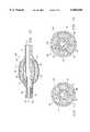
- FIG. 3is a cross section of the catheter taken along lines 3--3 in FIG. 2 illustrating the location and relative diameters of the three lumens;
- FIG. 4is an illustration of an alternative preferred method of the present invention whereby the single multi-lumen catheter is inserted into the ascending aorta with the catheter distal end oriented toward the aortic base for delivery of the cardioplegia solution to the aortic base, with the oxygenated blood being infused via catheter openings closely proximate the balloon and proximal of the balloon, as shown;
- FIG. 5is a sectional side view of an integral catheter utilized to conduct the method in FIG. 4, wherein the larger lumen terminates proximal of the balloon to infuse blood proximal of the downwardly extending catheter;
- FIG. 6is a cross section of the catheter taken along lines 6--6 in FIG. 5 illustrating the location and relative diameters of the three lumens;
- FIG. 7is a cross section of a catheter according to an alternative preferred embodiment having a double lobe balloon for creating a bloodless region in the aorta to perform an anastomosis of an artery;
- FIG. 8is a sectional sideview of a catheter according to an alternative preferred embodiment of the present invention suitable for occluding any body passageway, such as the aorta, seen to comprise an inner shell with a resilient material disposed thereabout and preferably encapsulated by an outer shell, the balloon having a nominal diameter when no pressure is applied, and an increased diameter when a pressure is applied to further expand the balloon;
- FIG. 9is a cross section of the balloon in FIG. 8 taken along line 9--9 to illustrate the resilient foam material encapsulated between the inner balloon shell and the outer balloon shell;
- FIG. 10is an illustration of the catheter of FIG. 8 in the expanded state with a pressure applied to the inner balloon shell, compressing the resilient foam material to further expand the overall diameter of the balloon;
- FIG. 11is a sectional view of an alternative preferred embodiment of the catheter shown in FIG. 8 whereby the resilient foam material is partitioned into sections, each section being separated by radially extending opposing edges about the catheter body;
- FIG. 12is a sectional view also taken along line 9--9 in FIG. 8 illustrating the embodiment of FIG. 11 in the expanded state, with the resilient foam sections expanding radially outward and away from one another to further increase the diameter of the catheter when pressure is applied to the balloon via the associated lumen;
- FIG. 13is yet another alternative preferred embodiment of the present invention from that of FIG. 8 and FIG. 11, when the resilient foam material is partitioned in the transverse direction with respect to the catheter body;
- FIG. 14is a sectional side view taken along line 14--14 in FIG. 13 illustrating the annular resilient foam sections
- FIG. 15is a sectional side view of the catheter of FIG. 13 illustrating the balloon in the expanded state, whereby the annular resilient foam sections expand outwardly and away from one another as pressure is applied via the associated balloon lumen to expand the outer balloon shell and increase the overall diameter of the balloon as a function of the pressure applied;
- FIG. 16is a sectional side view of a catheter having a fourth lumen for sensing pressure and/or venting the left ventricle of the heart when used in the orientation shown in FIG. 4.
- FIG. 1there is shown the first preferred method of the present invention.
- a single multi-lumen catheter 10is utilized for cannulating the ascending aorta 12 of a human heart 14.
- the right atriumis shown at 16, with the inferior vena cava being shown at 18 and superior vena cava being shown at 20.
- the subclavian arteryis shown at 22.
- Catheter 10is upwardly positioned within the ascending aorta 12, as shown, by first creating a suitable incision in the aorta proximate the aortic base, shown at 30.
- the distal end 32 of catheter 10is inserted into the incision of the aorta just over the aortic base, with the distal end 32 being advanced upwardly into the ascending aorta 12 until a reference marker 34 of catheter 10 is located adjacent incision 30.
- the distal end 72is oriented upwardly proximate the subclavian artery 22.
- An inflatable balloon 56 of catheter 10is carefully positioned between the aortic base but ahead of the left subclavian artery 22. In this orientation, a plurality of cardioplegia delivery openings 82 are oriented above and proximate the aortic base 42 of the heart.
- the balloon 56When the surgeon is prepared to put the patient on the extracorporeal circuit, the balloon 56 is inflated with air or a saline solution until the balloon's force can be felt by the surgeon's hand outside the aortic walls. This pressure assures that the aorta is fully occluded.
- the main lumen of the catheteris connected to an oxygenated blood source and infuses oxygenated blood out of the distal end of the catheter into the ascending aorta 12.
- the balloonWhen the balloon is fully inflated, the patient is properly connected to the extracorporeal circuit.
- cardioplegia solutionis delivered via the cardioplegia openings 82.
- This cardioplegia solutionis provided to the aorta between the aortic valve and the balloon clamp.
- the electrochemical action of the heartis stopped by infusing the heart muscle with the cardioplegia solution.
- This cardioplegia solutionis typically rich in potassium ions, which potassium ions interrupt the heart electrical signals resulting in a still heart. Stopping the heart gives a stable platform to effectively conduct the necessary procedures to the heart.
- catheter 10which is suited for achieving the method of the present invention.
- Catheter 10is seen to include an elongated catheter body 50 extending between a proximal end 52 and a distal end 54.
- an inflatable balloon 56which is secured circumferentially about the catheter by an adhesive or other suitable affixing means.
- the balloon 56may be filled with a foam or other resilient material, or simply left empty.
- a first smaller lumen 60extends longitudinally through catheter 10 and is in fluid communication within the interior 62 of balloon 56 via an opening 64 defined through body 50.
- a larger, second lumen 70extends longitudinally from the catheter proximal end through catheter 10 and opens at a distal opening 72 at distal end 54.
- a smaller third lumen 80extends from the proximal end of catheter 10 and terminates via a plurality of openings 82 defined through body 50.
- the openings 82are necessarily provided closely adjacent to the expandable balloon 56, but on the proximal side of the balloon, opposite the infusion distal opening 72. Thus, openings 72 and 82 are provided on opposite sides of balloon 56. In use, the inflated balloon 56 sealingly isolates openings 72 and 82 from one another for infusing blood out one side, and delivering cardioplegia solution out the other.
- Catheter body 50is preferably comprised of suitable flexible plastic material, such as silicone, PVC or other thermoplastics according to well known techniques.
- suitable flexible plastic materialsuch as silicone, PVC or other thermoplastics according to well known techniques.
- the diameter of the main infusion lumen 70is 0.250 inches.
- the diameter of the smaller inflating lumen 60is about 0.030 inches, and the cardioplegia lumen 82 has a diameter of about 0.100 inches.
- the relative diameters and locations of the three lumensare shown, again, with the main infusion lumen 70 having the largest diameter for delivering oxygenated blood to the ascending aorta.
- Cardioplegia and oxygenated bloodcan be alternately administered above the aortic base to control the response of the heart muscle to the cardioplegia during surgery, and assisting the heart in resuming a normal beat after surgery.
- FIG. 4there is shown an alternative method of the preferred invention whereby the orientation of a catheter 90 in the aorta is reversed. That is, the catheter 90 is inserted into incision 32 of the ascending aorta 12, but at a location further upward than that shown in FIG. 1, close to the subclavian artery 22 such that the catheter 90 extends downwardly, as shown.
- the distal end 54 of the catheteris advanced proximate the aortic base 42 and delivers cardioplegia solution therefrom.
- the openings 82 proximate balloon 56are positioned above the balloon 56, toward to subclavian artery 22 for infusion of oxygenated blood into the ascending aorta 12.
- the diameter of the lumen 80 infusing blood into the ascending aortais designed to have a much larger diameter than either the lumen 70 delivering cardioplegia solution to the distal end of the catheter or lumen 60 for inflating balloon 56.
- the diameter of the third lumen 80 of catheter 90is increased to have a diameter of between 0.250 and 0.350 inches for providing a suitable flow rate of oxygenated blood via openings 82 to the ascending aorta.
- the diameter of the second lumen 70 delivering the cardioplegia solution out distal opening 72is reduced to about 0.060 inches, which is suitable to deliver the necessary quantity of cardioplegia to the heart.
- the diameter of the first lumen 60is still 0.040 inches for inflating balloon 56.
- FIG. 6shows the relative orientation and diameters of the lumens of FIG. 5, taken along line 6--6.
- the catheter body 50is sufficiently flexible to allow maneuverability without kinking in the ascending aorta, allowing easy manipulation of the catheter within the aorta as shown in FIG. 1 and FIG. 4. If desired, the catheter could be designed to be extra resilient between the proximal end and opening 82 to further allow maneuverability of the catheter without kinking at the cannulation site 34.
- the longitudinal compactness of the operative features of both catheters 10 and 90facilitate the effective use of the single catheter.
- the inflated balloon 56typically has a diameter of about 1 inch, with the several openings 82 being provided immediately adjacent the balloon 56, and with the distal end and opening 72 being no more than 0.5 inches from balloon 56, as shown.
- the overall distance between the proximal openings 82 and the distal end 54 of catheter 50is ideally no more than about 2 inches for a use in the typical human heart.
- the dimensions to these features of the catheters 10 and 90is critical to facilitate effective use of the present invention.
- the blocked arteryis bypassed by attaching a saphenous vein graft to the artery distal to the occlusion while the other end of the graft is attached to the aorta.
- the surgeontypically performs an anastomosis to the artery first, followed by the anastamosis to the aorta. Since the aorta is filled with blood or cardioplegia, the surgeon may not have good visibility when an incision is made in the aorta. This reduces his ability to perform the anastamosis.
- a catheter having a specially shaped ballooncan be used.
- the 7is suitable, and has two bulbs or lobes 94 creating two seals 95 with the adjacent wall 96 of the aorta 12.
- the area 97 in between these two bulbs 94creates a bloodless area for the surgeon to perform the anastomosis in a clear field.
- catheter 92whereby the single balloon 93 is formed to have two lobes or bulbs 94 by securing an annular constriction, such as a ring 98 about the midsection of the balloon 93, allowing the two lobes 94 to remain in fluid communication with each other for inflation by the single inflation lumen 60.
- the ring 98is preferably secured to balloon 93 with a suitable adhesive.
- the balloon 93could simply be formed to have two lobes without the need for a ring, but this approach is more intricate and expensive.
- proximal balloonand a distal balloon could be provided, both in fluid communication with lumen 60 if desired, the proximal balloon being no more than 3 inches from the catheter distal end.
- the saphenous vein to be attached to the aortais shown at 99.
- FIG. 8there is shown generally at 100 a catheter with a uniquely designed balloon generally shown at 102.
- Catheter 100is similar to catheter 10 shown in FIG. 2 and catheter 90 shown in FIG. 5, wherein like numerals refer to like elements.
- Balloon 102is designed to allow even more control of the overall balloon diameter.
- the nominal state of the balloon 102is shown in FIG. 8, wherein a resilient material 104, such as foam, determines the nominal diameter.
- a pressureis applied to lumen 60, the overall diameter of the balloon can be increased approximately 20% beyond the nominal diameter, as shown in FIG. 10.
- the catheter 100 of the present inventionis ideally suitable for occluding an aorta, however, the present invention finds suitable preferred use for occluding other body passageways, such as the trachea, and limitation to use in a vessel of the heart is not to be inferred by the present invention.
- the present inventionis discussed with reference to occluding the aorta for illustration and clarity and for understanding the present invention.
- catheter 100is seen to have a catheter body 50 extending to a distal end 54, similar to catheter 10 in FIG. 2.
- Balloon 102has a first resilient inner shell 106 disposed about the catheter body 50 and covering the opening 64 of lumen 60.
- the inner shell 106is secured and sealed to catheter body 50 at each end thereof using a suitable adhesive, although heat could also be used to fuse the balloon shell 106 to the body of catheter 50.
- Disposed about the inner shell 106is an oval or generally egg-shaped unitary piece of the resilient material 104, such as foam.
- An outer resilient shell 110is seen to encapsulate the foam material 104, the foam material 104 residing between the inner shell 106 and the outer shell 110.
- the outer shell 110is comprised of a resilient material similar to that of inner shell 106, and overlaps the sealed edges of inner shell 106. Outer shell 110 is slipped over and sealed to both the distal ends of inner shell 106 and also to the catheter body 50 using a suitable adhesive, although heat or other suitable attachment means is appropriate. A coating may be used in place of outer shell 110 if desired.
- the outer curvature of resilient material 104defines the shape and diameter of the balloon 102.
- the resilient foam material 104is preferably comprised of an open-cell foam material, such as polyurethane, but could also comprise of a closed-cell material such as polyethylene if desired to eliminate the need for the outer shell 110.
- each end of the non-absorbing foam material 104is sealed to the catheter body 50 to allow inner balloon 106 to expand under the closed-cell material.
- the inner shell 106 and outer shell 110preferably comprise of a soft material such as silicone.
- the resilient material 104is preferably harder and less resilient than the inner shell 106 and the outer shell 110 to facilitate expansion of the outer shell 110.
- the resilient material 104may also comprise of a gel or other form changing material.
- the second perfusion lumen 70is seen to extend the length of the catheter 100 and terminate at opening 72.
- the third lumen 80can be provided as well if desired, terminating at proximate openings 82, as shown in FIG. 2.
- catheter 100with the balloon 102 in the expanded state when positive pressure is applied to the inner balloon shell 106 via the balloon lumen 60.
- the inner balloon shell 106is seen to expand and define a cavity 116. As the inner shell 106 expands, this compresses the resilient foam material 104 outwardly, as shown, further stretching the outer shell 110 to increase the overall diameter of the balloon 102. Due to the resiliency of the resilient material 104, the resilient material 104 will compress slightly whereby a 20% expansion of the inner shell 106 causes about a 10% expansion of the outer shell 110, and thus a 10% increase of the diameter of the balloon 102.
- the overall expansion of the balloon 102is a function of the pressure applied to the balloon lumen 60.
- the expansion of balloon 102is generally linear with respect to the pressure applied to lumen 60.
- the further expansion of the balloon 102 beyond its nominal diameteris especially useful for fully occluding a body passageway, such as an aorta, when the nominal diameter of the balloon is not quite sufficient to occlude the vessel, but wherein further expansion of the balloon does suitably occlude the vessel to prevent fluid flow therethrough.
- a body passagewaysuch as the aorta
- the present inventionfinds technical advantages by allowing the balloon 102 to customly fit to the inner diameter of a body passageway needing to be occluded, such as the aorta, a trachea, etc.
- Balloon 120is seen to be substantially identical to balloon 102 in FIG. 8, wherein like numerals refer to like elements.
- the resilient foam material 104is seen to be radially partitioned into a plurality of segments 122 circumferentially about the catheter body 50.
- the interfacing edges 124 of the sections 122engage one another, as shown, with the overall diameter of the resilient material 104 being the same as that shown in FIG. 8.
- the interfacing edges 124 of sections 122extend in the radial direction, as shown, with the width of each section 22 being approximately equal.
- each of the resilient foam sections 122are seen to be separated from one another by corresponding gaps 128.
- thisfurther facilitates the expansion of the foam material 104 in the radial direction when a pressure is applied via lumen 60.
- the overall expansion of the foam material 104, and thus the outer shell 110is increased from that of the embodiment in FIG. 8.
- the balloon 102 of the embodiment of FIG. 8may increase 10%, but the overall diameter of balloon 120 in the embodiment of FIG. 11 will increase about 20%.
- Each of the resilient material sections 122are still encapsulated between the inner shell 106 and the outer shell 110, as described with regards to balloon 102 in FIG. 8.
- FIG. 13yet another alternative embodiment of a catheter is shown generally at 130 having a balloon 131.
- Catheter 130is generally the same as catheter 100 in FIG. 8, wherein like numerals refer to like elements.
- the resilient foam material 104is partitioned into annular sections 132.
- Each of the annular sections 132abut against each other along section edges 134, each section 132 being concentric with each other about the catheter body 50, as shown.
- a cross section of the modified balloon 131 taken along line 14--14is shown in FIG. 14.
- FIG. 14there is shown the modified balloon 131 in its expanded state, whereby the inner shell 106 is expanded by applying a pressure via balloon 60.
- the inner shell 106expands to define the inner cavity 116.
- each of the annular sections 132expands outwardly, and separate from one another to define gaps 136.
- the expanding annular sections 132expand radially outward to expand the outer shell 110, as shown, to further increase the overall diameter of the balloon 131.
- the resilient material 104Similar to the partitioned foam material shown in FIG. 11, by partitioning the resilient material 104 to provide a modular resilient sections, the resilient material 104 will compress and expand more easily to increase the outer diameter of shell 110 for a given pressure to lumen 60.
- the curvature of the outer shell 110will conform to the inner curvature of the body passageway that the balloon 131 is inserted into. For instance, if the inner wall of the aorta is curved, the outer diameter of the balloon 131 will conform to this curvature to fully occlude the passageway when inflated.
- the novel balloon 131adapts to the particular patient into which it is inserted.
- the modular sections 122 in FIG. 11also allow the diameter of the balloon to also conform to the body passageway to fully occlude the passageway and prevent flow.
- a catheter 140 having a fourth lumen 142is provided through the catheter body 50 and terminate at the proximal end of the balloon, as shown, but could also be provided distal of the balloon, if desired, to provide for pressure sensing or venting during use.
- the fourth lumenallows a body passageway pressure to be ascertained which is desirable to determine if the balloon is occluding the passageway as intended. If the pressure detected via this fourth lumen 142 indicates that the balloon 56 is in its unexpanded state, or is not fully occluding the body passageway, pressure can be applied via lumen 60 to inflate the balloon, as shown in FIG. 10, FIG. 12 and FIG.
- the fourth lumenalso allows venting of the left ventricle of excess cardioplegia and blood to protect the endocardium when the apex of the heart is elevated.
- the fourth lumen 142also permits a malleable rod or material to be selectively inserted therein to facilitate customly shaping the curvature of the catheter body.
- catheters having a unique balloonare ideally suited for use for occluding the aorta, and are also ideally suited for use with the catheters 10 and 90 for use as a multi-lumen catheter, the unique balloon catheters having a resilient material are well suited for performing other surgical procedures whereby clamping of a body passageway is desired.
- a single lumen catheter having a unique balloon with a resilient interiorcan be provided for occluding a vessel, such as the trachea.
- the present inventionis suitable for other percutaneous procedures besides aortic perfusion.
- FIGS. 8-16are suitable for implementation in the multi-lumen aortic clamp catheters of FIG. 2 and FIG. 5, but also have more general purpose uses to occlude any body passageway, including passageways having unique curvatures and/or varying diameters.
- the partitioned resilient sections in the embodiments of FIG. 11 and FIG. 15are well suited to conform to the inner diameter of the passageway and fully occlude the passageway to prevent fluid flow therethrough.
- the additional expansion capabilities of the balloons including the resilient sectionsallows the catheter to conform to the particular passageway of many patients.
Landscapes
- Health & Medical Sciences (AREA)
- Life Sciences & Earth Sciences (AREA)
- Heart & Thoracic Surgery (AREA)
- Engineering & Computer Science (AREA)
- Biophysics (AREA)
- Pulmonology (AREA)
- Child & Adolescent Psychology (AREA)
- Anesthesiology (AREA)
- Biomedical Technology (AREA)
- Hematology (AREA)
- Animal Behavior & Ethology (AREA)
- General Health & Medical Sciences (AREA)
- Public Health (AREA)
- Veterinary Medicine (AREA)
- Media Introduction/Drainage Providing Device (AREA)
Abstract
Description
Claims (24)
Priority Applications (1)
| Application Number | Priority Date | Filing Date | Title |
|---|---|---|---|
| US08/846,654US6068608A (en) | 1997-05-01 | 1997-05-01 | Method of using integral aortic arch infusion clamp |
Applications Claiming Priority (1)
| Application Number | Priority Date | Filing Date | Title |
|---|---|---|---|
| US08/846,654US6068608A (en) | 1997-05-01 | 1997-05-01 | Method of using integral aortic arch infusion clamp |
Publications (1)
| Publication Number | Publication Date |
|---|---|
| US6068608Atrue US6068608A (en) | 2000-05-30 |
Family
ID=25298557
Family Applications (1)
| Application Number | Title | Priority Date | Filing Date |
|---|---|---|---|
| US08/846,654Expired - Fee RelatedUS6068608A (en) | 1997-05-01 | 1997-05-01 | Method of using integral aortic arch infusion clamp |
Country Status (1)
| Country | Link |
|---|---|
| US (1) | US6068608A (en) |
Cited By (14)
| Publication number | Priority date | Publication date | Assignee | Title |
|---|---|---|---|---|
| US20020016564A1 (en)* | 2000-05-31 | 2002-02-07 | Courtney Brian K. | Embolization protection sytem for vascular procedures |
| US6447521B1 (en)* | 2000-09-15 | 2002-09-10 | Advanced Cardiovascular Systems, Inc. | Foamed inner member cover stent retention and method of use |
| US6517524B2 (en) | 2001-02-15 | 2003-02-11 | Genesse Biomedical, Inc. | Occlusive cannula for aortic blood flow and air venting |
| US20040102797A1 (en)* | 1999-04-05 | 2004-05-27 | Coalescent Surgical, Inc. | Apparatus and methods for anastomosis |
| US20040193099A1 (en)* | 2001-07-17 | 2004-09-30 | Macmahon John M. | Fluid exchange system for controlled and localized irrigation and aspiration |
| US20050004517A1 (en)* | 2000-06-02 | 2005-01-06 | Courtney Brian K. | Embolization protection system for vascular procedures |
| US20050165427A1 (en)* | 2004-01-22 | 2005-07-28 | Jahns Scott E. | Vessel sealing devices |
| US6951555B1 (en) | 1998-03-16 | 2005-10-04 | Chase Medical, L.P. | Catheter having integral expandable/collapsible lumen |
| US20060089588A1 (en)* | 1999-09-13 | 2006-04-27 | Albertus Scheule | Aortic balloon occlusion cannula |
| US20090234177A1 (en)* | 2008-02-29 | 2009-09-17 | Lebovic Gail S | Systems and methods for delivering radiation therapy |
| US20110022152A1 (en)* | 2007-12-21 | 2011-01-27 | Axel Grandt | Double layered balloons in medical devices |
| US20140052044A1 (en)* | 2011-04-01 | 2014-02-20 | Martin Joseph Crnkovich | Apparatus and method for venting gas from a liquid |
| JP2016131856A (en)* | 2015-01-22 | 2016-07-25 | テルモ株式会社 | Balloon and intraluminal therapy method |
| US9642999B2 (en) | 2010-02-12 | 2017-05-09 | Varian Medical Systems, Inc. | Brachytherapy applicator |
Citations (81)
| Publication number | Priority date | Publication date | Assignee | Title |
|---|---|---|---|---|
| US35352A (en)* | 1862-05-20 | Improved hay-rigging | ||
| US35459A (en)* | 1862-06-03 | Improvement in bird-cages | ||
| US2701559A (en)* | 1951-08-02 | 1955-02-08 | William A Cooper | Apparatus for exfoliating and collecting diagnostic material from inner walls of hollow viscera |
| US3640282A (en)* | 1970-08-06 | 1972-02-08 | Jack M Kamen | Tracheal tube with normally expanded balloon cuff |
| US4129129A (en)* | 1977-03-18 | 1978-12-12 | Sarns, Inc. | Venous return catheter and a method of using the same |
| GB1547328A (en)* | 1978-01-19 | 1979-06-13 | Celestin L R | Apparatus for insertion into a body cavity |
| EP0028025A1 (en)* | 1979-10-25 | 1981-05-06 | Dala Invest AB | Method and device for the production of microdroplets of liquid |
| US4328056A (en)* | 1980-07-09 | 1982-05-04 | Sherwood Medical Industries Inc. | Method of making a cuffed tube |
| US4413989A (en)* | 1980-09-08 | 1983-11-08 | Angiomedics Corporation | Expandable occlusion apparatus |
| US4417576A (en)* | 1982-02-25 | 1983-11-29 | Baran Ostap E | Double-wall surgical cuff |
| US4423725A (en)* | 1982-03-31 | 1984-01-03 | Baran Ostap E | Multiple surgical cuff |
| US4531936A (en)* | 1981-01-29 | 1985-07-30 | Gordon Robert T | Device and method for the selective delivery of drugs to the myocardium |
| US4592340A (en)* | 1984-05-02 | 1986-06-03 | Boyles Paul W | Artificial catheter means |
| US4596552A (en)* | 1983-06-10 | 1986-06-24 | Dlp Inc. | Cardioplegia cannula |
| US4601706A (en)* | 1984-12-03 | 1986-07-22 | Rene Aillon | Central venous pressure catheter for preventing air embolism and method of making |
| US4610662A (en)* | 1981-11-24 | 1986-09-09 | Schneider Medintag Ag | Method for the elimination or the enlargement of points of constriction in vessels carrying body fluids |
| US4648384A (en)* | 1984-11-21 | 1987-03-10 | Schmukler Robert E | Retrograde coronary sinus perfusion device and method |
| EP0218275A1 (en)* | 1985-08-30 | 1987-04-15 | Fijneman, Martinus Jacobus Antonius Johannes | Multi-purpose catheter |
| US4676778A (en)* | 1986-10-27 | 1987-06-30 | Nelson Jr Richard L | Long intestinal catheter with sump |
| US4689041A (en)* | 1984-01-20 | 1987-08-25 | Eliot Corday | Retrograde delivery of pharmacologic and diagnostic agents via venous circulation |
| US4741328A (en)* | 1985-03-14 | 1988-05-03 | Shlomo Gabbay | Means for intraaortic assist and method of positioning a catheter therefor |
| EP0266957A2 (en)* | 1986-11-04 | 1988-05-11 | C.R. Bard, Inc. | Two balloons angiplasty catheter |
| US4781682A (en)* | 1987-08-13 | 1988-11-01 | Patel Piyush V | Catheter having support flaps and method of inserting catheter |
| US4927412A (en)* | 1988-12-08 | 1990-05-22 | Retroperfusion Systems, Inc. | Coronary sinus catheter |
| US4943277A (en)* | 1989-03-24 | 1990-07-24 | Bolling Steven F | Retrograde coronary sinus cardioplegia cannula and method for using same in heart surgery |
| US4988515A (en)* | 1988-01-28 | 1991-01-29 | The Regents Of The Univ. Of Calif. | Cardioplegic solution |
| EP0417781A1 (en)* | 1989-09-14 | 1991-03-20 | Terumo Kabushiki Kaisha | Cardiac output measuring catheter |
| US5011469A (en)* | 1988-08-29 | 1991-04-30 | Shiley, Inc. | Peripheral cardiopulmonary bypass and coronary reperfusion system |
| US5013296A (en)* | 1989-09-21 | 1991-05-07 | Research Medical, Inc. | Antegrade cardioplegia cannula |
| US5021045A (en)* | 1988-04-28 | 1991-06-04 | Research Medical, Inc. | Retrograde venous cardioplegia catheters and methods of use and manufacture |
| US5024668A (en)* | 1987-01-20 | 1991-06-18 | Rocky Mountain Research, Inc. | Retrograde perfusion system, components and method |
| US5033998A (en)* | 1984-01-20 | 1991-07-23 | Eliot Corday | Retrograde delivery of pharmacologic and diagnostic agents via venous circulation |
| US5090960A (en)* | 1990-01-12 | 1992-02-25 | Don Michael T Anthony | Regional perfusion dissolution catheter |
| US5135474A (en)* | 1990-08-03 | 1992-08-04 | University Of Medicine And Dentistry Of New Jersey | Hepatic bypass catheter |
| US5135484A (en)* | 1990-05-09 | 1992-08-04 | Pioneering Technologies, Inc. | Method of removing plaque from vessels |
| US5149330A (en)* | 1991-01-10 | 1992-09-22 | The Kendall Company | Catheter convertible from single to multilumen |
| US5151087A (en)* | 1991-08-30 | 1992-09-29 | Dlp, Inc. | Aortic root cannula |
| US5167628A (en)* | 1991-05-02 | 1992-12-01 | Boyles Paul W | Aortic balloon catheter assembly for indirect infusion of the coronary arteries |
| US5171218A (en)* | 1992-01-02 | 1992-12-15 | Trustees Of Boston University | Bidirectional femoral arterial cannula |
| US5192290A (en)* | 1990-08-29 | 1993-03-09 | Applied Medical Resources, Inc. | Embolectomy catheter |
| US5197952A (en)* | 1990-06-13 | 1993-03-30 | Dlp, Inc. | Auto-inflating catheter cuff |
| US5213576A (en)* | 1991-06-11 | 1993-05-25 | Cordis Corporation | Therapeutic porous balloon catheter |
| US5221258A (en)* | 1991-01-22 | 1993-06-22 | Shturman Technologies, Inc. | Introduction balloon catheter |
| US5232444A (en)* | 1988-06-25 | 1993-08-03 | Just Hansjoerg | Dilatation catheter |
| US5308323A (en)* | 1988-06-06 | 1994-05-03 | Sumitomo Electric Industries. Ltd. | Multiple compartment balloon catheter |
| US5308325A (en)* | 1991-01-28 | 1994-05-03 | Corpak, Inc. | Retention balloon for percutaneous catheter |
| US5312344A (en)* | 1991-02-25 | 1994-05-17 | Grinfeld Roberto R | Arterial perfusion cannula for extracorporeal circulation and other uses |
| US5324260A (en)* | 1992-04-27 | 1994-06-28 | Minnesota Mining And Manufacturing Company | Retrograde coronary sinus catheter |
| US5334142A (en)* | 1991-09-09 | 1994-08-02 | New York University | Selective aortic perfusion system |
| US5338298A (en)* | 1993-06-04 | 1994-08-16 | C. R. Bard, Inc. | Double-tapered balloon |
| US5360403A (en)* | 1990-05-16 | 1994-11-01 | Lake Region Manufacturing Co., Inc. | Balloon catheter with lumen occluder |
| US5378230A (en)* | 1993-11-01 | 1995-01-03 | Mahurkar; Sakharam D. | Triple-lumen critical care catheter |
| US5395330A (en)* | 1990-06-13 | 1995-03-07 | Dlp, Inc. | Auto-inflating catheter cuff |
| US5395331A (en)* | 1992-04-27 | 1995-03-07 | Minnesota Mining And Manufacturing Company | Retrograde coronary sinus catheter having a ribbed balloon |
| US5423745A (en)* | 1988-04-28 | 1995-06-13 | Research Medical, Inc. | Irregular surface balloon catheters for body passageways and methods of use |
| WO1995017919A1 (en)* | 1993-12-27 | 1995-07-06 | Heartport, Inc. | Thoracoscopic devices and methods for arresting the heart |
| US5433700A (en)* | 1992-12-03 | 1995-07-18 | Stanford Surgical Technologies, Inc. | Method for intraluminally inducing cardioplegic arrest and catheter for use therein |
| EP0664104A2 (en)* | 1994-01-24 | 1995-07-26 | Micro Therapeutics, Inc. | Balloon catheter for occluding aneurysms or branch vessels |
| US5437637A (en)* | 1991-11-08 | 1995-08-01 | Baxter International Inc. | Transport catheter |
| US5439444A (en)* | 1991-01-28 | 1995-08-08 | Corpak, Inc. | Pre-formed member for percutaneous catheter |
| US5443446A (en)* | 1991-04-04 | 1995-08-22 | Shturman Cardiology Systems, Inc. | Method and apparatus for in vivo heart valve decalcification |
| US5443448A (en)* | 1992-05-26 | 1995-08-22 | Dlp, Inc. | Dual flexible introducer and cannula |
| US5451207A (en)* | 1994-04-25 | 1995-09-19 | The Regents Of The University Of California | Method of coronary plaque removal with bypass and perfusion |
| US5451204A (en)* | 1988-07-22 | 1995-09-19 | Yoon; Inbae | Multifunctional devices for endoscopic surgical procedures |
| US5452733A (en)* | 1993-02-22 | 1995-09-26 | Stanford Surgical Technologies, Inc. | Methods for performing thoracoscopic coronary artery bypass |
| US5458574A (en)* | 1994-03-16 | 1995-10-17 | Heartport, Inc. | System for performing a cardiac procedure |
| US5458575A (en)* | 1993-02-16 | 1995-10-17 | Boston Scientific Corp. | Perfusion catheter having a cylindrical array of balloons |
| WO1995032756A1 (en)* | 1994-05-27 | 1995-12-07 | Medtronic, Inc. | Balloon catheter |
| US5478309A (en)* | 1994-05-27 | 1995-12-26 | William P. Sweezer, Jr. | Catheter system and method for providing cardiopulmonary bypass pump support during heart surgery |
| US5501667A (en)* | 1994-03-15 | 1996-03-26 | Cordis Corporation | Perfusion balloon and method of use and manufacture |
| US5505598A (en)* | 1994-07-29 | 1996-04-09 | Wirtgen America, Inc. | Milling machine with multi-width cutter |
| US5533957A (en)* | 1994-05-06 | 1996-07-09 | Trustees Of Boston University | Method of tissue retroperfusion |
| US5558644A (en)* | 1991-07-16 | 1996-09-24 | Heartport, Inc. | Retrograde delivery catheter and method for inducing cardioplegic arrest |
| WO1996030072A1 (en)* | 1995-03-30 | 1996-10-03 | Heartport, Inc. | System and methods for performing endovascular procedures |
| US5571215A (en)* | 1993-02-22 | 1996-11-05 | Heartport, Inc. | Devices and methods for intracardiac procedures |
| US5584803A (en)* | 1991-07-16 | 1996-12-17 | Heartport, Inc. | System for cardiac procedures |
| WO1996040347A1 (en)* | 1995-06-07 | 1996-12-19 | Heartport, Inc. | Endovascular system for arresting the heart |
| US5609571A (en)* | 1995-01-26 | 1997-03-11 | Sorin Biomedical Inc. | Apparatus and method of cardioplegia delivery |
| US5611775A (en)* | 1993-03-15 | 1997-03-18 | Advanced Cardiovascular Systems, Inc. | Method of delivery therapeutic or diagnostic liquid into tissue surrounding a body lumen |
| US5616149A (en)* | 1990-07-03 | 1997-04-01 | Cedars-Sinai Medical Center | Balloon catheter with cutting edge |
| US5658311A (en)* | 1996-07-05 | 1997-08-19 | Schneider (Usa) Inc. | High pressure expander bundle for large diameter stent deployment |
- 1997
- 1997-05-01USUS08/846,654patent/US6068608A/ennot_activeExpired - Fee Related
Patent Citations (88)
| Publication number | Priority date | Publication date | Assignee | Title |
|---|---|---|---|---|
| US35352A (en)* | 1862-05-20 | Improved hay-rigging | ||
| US35459A (en)* | 1862-06-03 | Improvement in bird-cages | ||
| US2701559A (en)* | 1951-08-02 | 1955-02-08 | William A Cooper | Apparatus for exfoliating and collecting diagnostic material from inner walls of hollow viscera |
| US3640282A (en)* | 1970-08-06 | 1972-02-08 | Jack M Kamen | Tracheal tube with normally expanded balloon cuff |
| US4129129A (en)* | 1977-03-18 | 1978-12-12 | Sarns, Inc. | Venous return catheter and a method of using the same |
| GB1547328A (en)* | 1978-01-19 | 1979-06-13 | Celestin L R | Apparatus for insertion into a body cavity |
| EP0028025A1 (en)* | 1979-10-25 | 1981-05-06 | Dala Invest AB | Method and device for the production of microdroplets of liquid |
| US4328056A (en)* | 1980-07-09 | 1982-05-04 | Sherwood Medical Industries Inc. | Method of making a cuffed tube |
| US4413989A (en)* | 1980-09-08 | 1983-11-08 | Angiomedics Corporation | Expandable occlusion apparatus |
| US4531936A (en)* | 1981-01-29 | 1985-07-30 | Gordon Robert T | Device and method for the selective delivery of drugs to the myocardium |
| US4610662A (en)* | 1981-11-24 | 1986-09-09 | Schneider Medintag Ag | Method for the elimination or the enlargement of points of constriction in vessels carrying body fluids |
| US4417576A (en)* | 1982-02-25 | 1983-11-29 | Baran Ostap E | Double-wall surgical cuff |
| US4423725A (en)* | 1982-03-31 | 1984-01-03 | Baran Ostap E | Multiple surgical cuff |
| US4596552A (en)* | 1983-06-10 | 1986-06-24 | Dlp Inc. | Cardioplegia cannula |
| US5033998A (en)* | 1984-01-20 | 1991-07-23 | Eliot Corday | Retrograde delivery of pharmacologic and diagnostic agents via venous circulation |
| US4689041A (en)* | 1984-01-20 | 1987-08-25 | Eliot Corday | Retrograde delivery of pharmacologic and diagnostic agents via venous circulation |
| US4592340A (en)* | 1984-05-02 | 1986-06-03 | Boyles Paul W | Artificial catheter means |
| US4648384A (en)* | 1984-11-21 | 1987-03-10 | Schmukler Robert E | Retrograde coronary sinus perfusion device and method |
| US4601706A (en)* | 1984-12-03 | 1986-07-22 | Rene Aillon | Central venous pressure catheter for preventing air embolism and method of making |
| US4741328A (en)* | 1985-03-14 | 1988-05-03 | Shlomo Gabbay | Means for intraaortic assist and method of positioning a catheter therefor |
| EP0218275A1 (en)* | 1985-08-30 | 1987-04-15 | Fijneman, Martinus Jacobus Antonius Johannes | Multi-purpose catheter |
| US4676778A (en)* | 1986-10-27 | 1987-06-30 | Nelson Jr Richard L | Long intestinal catheter with sump |
| EP0266957A2 (en)* | 1986-11-04 | 1988-05-11 | C.R. Bard, Inc. | Two balloons angiplasty catheter |
| US5024668A (en)* | 1987-01-20 | 1991-06-18 | Rocky Mountain Research, Inc. | Retrograde perfusion system, components and method |
| US4781682A (en)* | 1987-08-13 | 1988-11-01 | Patel Piyush V | Catheter having support flaps and method of inserting catheter |
| US4988515A (en)* | 1988-01-28 | 1991-01-29 | The Regents Of The Univ. Of Calif. | Cardioplegic solution |
| US5423745A (en)* | 1988-04-28 | 1995-06-13 | Research Medical, Inc. | Irregular surface balloon catheters for body passageways and methods of use |
| US5021045A (en)* | 1988-04-28 | 1991-06-04 | Research Medical, Inc. | Retrograde venous cardioplegia catheters and methods of use and manufacture |
| US5308323A (en)* | 1988-06-06 | 1994-05-03 | Sumitomo Electric Industries. Ltd. | Multiple compartment balloon catheter |
| US5232444A (en)* | 1988-06-25 | 1993-08-03 | Just Hansjoerg | Dilatation catheter |
| US5451204A (en)* | 1988-07-22 | 1995-09-19 | Yoon; Inbae | Multifunctional devices for endoscopic surgical procedures |
| US5011469A (en)* | 1988-08-29 | 1991-04-30 | Shiley, Inc. | Peripheral cardiopulmonary bypass and coronary reperfusion system |
| US4927412A (en)* | 1988-12-08 | 1990-05-22 | Retroperfusion Systems, Inc. | Coronary sinus catheter |
| US4943277A (en)* | 1989-03-24 | 1990-07-24 | Bolling Steven F | Retrograde coronary sinus cardioplegia cannula and method for using same in heart surgery |
| EP0417781A1 (en)* | 1989-09-14 | 1991-03-20 | Terumo Kabushiki Kaisha | Cardiac output measuring catheter |
| US5013296A (en)* | 1989-09-21 | 1991-05-07 | Research Medical, Inc. | Antegrade cardioplegia cannula |
| US5090960A (en)* | 1990-01-12 | 1992-02-25 | Don Michael T Anthony | Regional perfusion dissolution catheter |
| US5135484A (en)* | 1990-05-09 | 1992-08-04 | Pioneering Technologies, Inc. | Method of removing plaque from vessels |
| US5360403A (en)* | 1990-05-16 | 1994-11-01 | Lake Region Manufacturing Co., Inc. | Balloon catheter with lumen occluder |
| US5290231A (en)* | 1990-06-13 | 1994-03-01 | Dlp, Inc. | Auto-inflating catheter cuff |
| US5197952A (en)* | 1990-06-13 | 1993-03-30 | Dlp, Inc. | Auto-inflating catheter cuff |
| US5395330A (en)* | 1990-06-13 | 1995-03-07 | Dlp, Inc. | Auto-inflating catheter cuff |
| US5616149A (en)* | 1990-07-03 | 1997-04-01 | Cedars-Sinai Medical Center | Balloon catheter with cutting edge |
| US5135474A (en)* | 1990-08-03 | 1992-08-04 | University Of Medicine And Dentistry Of New Jersey | Hepatic bypass catheter |
| US5192290A (en)* | 1990-08-29 | 1993-03-09 | Applied Medical Resources, Inc. | Embolectomy catheter |
| US5149330A (en)* | 1991-01-10 | 1992-09-22 | The Kendall Company | Catheter convertible from single to multilumen |
| US5221258A (en)* | 1991-01-22 | 1993-06-22 | Shturman Technologies, Inc. | Introduction balloon catheter |
| US5439444A (en)* | 1991-01-28 | 1995-08-08 | Corpak, Inc. | Pre-formed member for percutaneous catheter |
| US5308325A (en)* | 1991-01-28 | 1994-05-03 | Corpak, Inc. | Retention balloon for percutaneous catheter |
| US5312344A (en)* | 1991-02-25 | 1994-05-17 | Grinfeld Roberto R | Arterial perfusion cannula for extracorporeal circulation and other uses |
| US5443446A (en)* | 1991-04-04 | 1995-08-22 | Shturman Cardiology Systems, Inc. | Method and apparatus for in vivo heart valve decalcification |
| US5167628A (en)* | 1991-05-02 | 1992-12-01 | Boyles Paul W | Aortic balloon catheter assembly for indirect infusion of the coronary arteries |
| US5213576A (en)* | 1991-06-11 | 1993-05-25 | Cordis Corporation | Therapeutic porous balloon catheter |
| US5558644A (en)* | 1991-07-16 | 1996-09-24 | Heartport, Inc. | Retrograde delivery catheter and method for inducing cardioplegic arrest |
| US5584803A (en)* | 1991-07-16 | 1996-12-17 | Heartport, Inc. | System for cardiac procedures |
| US5151087A (en)* | 1991-08-30 | 1992-09-29 | Dlp, Inc. | Aortic root cannula |
| USRE35459E (en) | 1991-08-30 | 1997-02-18 | Medtronic, Inc. | Aortic root cannula |
| US5334142A (en)* | 1991-09-09 | 1994-08-02 | New York University | Selective aortic perfusion system |
| US5662620A (en)* | 1991-11-08 | 1997-09-02 | Baxter International, Inc. | Transport catheter |
| US5437637A (en)* | 1991-11-08 | 1995-08-01 | Baxter International Inc. | Transport catheter |
| US5171218A (en)* | 1992-01-02 | 1992-12-15 | Trustees Of Boston University | Bidirectional femoral arterial cannula |
| US5395331A (en)* | 1992-04-27 | 1995-03-07 | Minnesota Mining And Manufacturing Company | Retrograde coronary sinus catheter having a ribbed balloon |
| US5620418A (en)* | 1992-04-27 | 1997-04-15 | Minnesota Mining And Manufacturing Company | Retrograde coronary sinus catheter |
| US5324260A (en)* | 1992-04-27 | 1994-06-28 | Minnesota Mining And Manufacturing Company | Retrograde coronary sinus catheter |
| US5443448A (en)* | 1992-05-26 | 1995-08-22 | Dlp, Inc. | Dual flexible introducer and cannula |
| US5433700A (en)* | 1992-12-03 | 1995-07-18 | Stanford Surgical Technologies, Inc. | Method for intraluminally inducing cardioplegic arrest and catheter for use therein |
| USRE35352E (en) | 1992-12-03 | 1996-10-15 | Heartport, Inc. | Method for intraluminally inducing cardioplegic arrest and catheter for use therein |
| US5487730A (en)* | 1992-12-30 | 1996-01-30 | Medtronic, Inc. | Balloon catheter with balloon surface retention means |
| US5458575A (en)* | 1993-02-16 | 1995-10-17 | Boston Scientific Corp. | Perfusion catheter having a cylindrical array of balloons |
| US5571215A (en)* | 1993-02-22 | 1996-11-05 | Heartport, Inc. | Devices and methods for intracardiac procedures |
| US5452733A (en)* | 1993-02-22 | 1995-09-26 | Stanford Surgical Technologies, Inc. | Methods for performing thoracoscopic coronary artery bypass |
| US5611775A (en)* | 1993-03-15 | 1997-03-18 | Advanced Cardiovascular Systems, Inc. | Method of delivery therapeutic or diagnostic liquid into tissue surrounding a body lumen |
| US5338298A (en)* | 1993-06-04 | 1994-08-16 | C. R. Bard, Inc. | Double-tapered balloon |
| US5378230A (en)* | 1993-11-01 | 1995-01-03 | Mahurkar; Sakharam D. | Triple-lumen critical care catheter |
| WO1995017919A1 (en)* | 1993-12-27 | 1995-07-06 | Heartport, Inc. | Thoracoscopic devices and methods for arresting the heart |
| EP0664104A2 (en)* | 1994-01-24 | 1995-07-26 | Micro Therapeutics, Inc. | Balloon catheter for occluding aneurysms or branch vessels |
| US5501667A (en)* | 1994-03-15 | 1996-03-26 | Cordis Corporation | Perfusion balloon and method of use and manufacture |
| US5458574A (en)* | 1994-03-16 | 1995-10-17 | Heartport, Inc. | System for performing a cardiac procedure |
| US5451207A (en)* | 1994-04-25 | 1995-09-19 | The Regents Of The University Of California | Method of coronary plaque removal with bypass and perfusion |
| US5533957A (en)* | 1994-05-06 | 1996-07-09 | Trustees Of Boston University | Method of tissue retroperfusion |
| US5597377A (en)* | 1994-05-06 | 1997-01-28 | Trustees Of Boston University | Coronary sinus reperfusion catheter |
| US5478309A (en)* | 1994-05-27 | 1995-12-26 | William P. Sweezer, Jr. | Catheter system and method for providing cardiopulmonary bypass pump support during heart surgery |
| WO1995032756A1 (en)* | 1994-05-27 | 1995-12-07 | Medtronic, Inc. | Balloon catheter |
| US5505598A (en)* | 1994-07-29 | 1996-04-09 | Wirtgen America, Inc. | Milling machine with multi-width cutter |
| US5609571A (en)* | 1995-01-26 | 1997-03-11 | Sorin Biomedical Inc. | Apparatus and method of cardioplegia delivery |
| WO1996030072A1 (en)* | 1995-03-30 | 1996-10-03 | Heartport, Inc. | System and methods for performing endovascular procedures |
| WO1996040347A1 (en)* | 1995-06-07 | 1996-12-19 | Heartport, Inc. | Endovascular system for arresting the heart |
| US5658311A (en)* | 1996-07-05 | 1997-08-19 | Schneider (Usa) Inc. | High pressure expander bundle for large diameter stent deployment |
Cited By (34)
| Publication number | Priority date | Publication date | Assignee | Title |
|---|---|---|---|---|
| US6951555B1 (en) | 1998-03-16 | 2005-10-04 | Chase Medical, L.P. | Catheter having integral expandable/collapsible lumen |
| US8211131B2 (en) | 1999-04-05 | 2012-07-03 | Medtronic, Inc. | Apparatus and methods for anastomosis |
| US7938840B2 (en) | 1999-04-05 | 2011-05-10 | Medtronic, Inc. | Apparatus and methods for anastomosis |
| US20040102797A1 (en)* | 1999-04-05 | 2004-05-27 | Coalescent Surgical, Inc. | Apparatus and methods for anastomosis |
| US20060089588A1 (en)* | 1999-09-13 | 2006-04-27 | Albertus Scheule | Aortic balloon occlusion cannula |
| US20020016564A1 (en)* | 2000-05-31 | 2002-02-07 | Courtney Brian K. | Embolization protection sytem for vascular procedures |
| US7108677B2 (en)* | 2000-05-31 | 2006-09-19 | Kerberos Proximal Solutions, Inc. | Embolization protection system for vascular procedures |
| US20050004517A1 (en)* | 2000-06-02 | 2005-01-06 | Courtney Brian K. | Embolization protection system for vascular procedures |
| US8435225B2 (en)* | 2000-06-02 | 2013-05-07 | Fox Hollow Technologies, Inc. | Embolization protection system for vascular procedures |
| US6447521B1 (en)* | 2000-09-15 | 2002-09-10 | Advanced Cardiovascular Systems, Inc. | Foamed inner member cover stent retention and method of use |
| US6517524B2 (en) | 2001-02-15 | 2003-02-11 | Genesse Biomedical, Inc. | Occlusive cannula for aortic blood flow and air venting |
| US8562555B2 (en) | 2001-07-17 | 2013-10-22 | John M. MacMahon | Fluid exchange system for controlled and localized irrigation and aspiration |
| US7530976B2 (en) | 2001-07-17 | 2009-05-12 | Fox Hollow Technologies, Inc. | Fluid exchange system for controlled and localized irrigation and aspiration |
| US20040193099A1 (en)* | 2001-07-17 | 2004-09-30 | Macmahon John M. | Fluid exchange system for controlled and localized irrigation and aspiration |
| US20060276743A1 (en)* | 2001-07-17 | 2006-12-07 | Kerberos Proximal Solutions, Inc. | Fluid exchange system for controlled and localized irrigation and aspiration |
| US20050020973A1 (en)* | 2001-07-17 | 2005-01-27 | Macmahon John M. | Fluid exchange system for controlled and localized irrigation and aspiration |
| US20070073343A1 (en)* | 2004-01-22 | 2007-03-29 | Jahns Scott E | Vessel sealing devices |
| US10278723B2 (en) | 2004-01-22 | 2019-05-07 | Medtronic, Inc. | Vessel sealing devices |
| US20050165427A1 (en)* | 2004-01-22 | 2005-07-28 | Jahns Scott E. | Vessel sealing devices |
| US20100174281A1 (en)* | 2004-01-22 | 2010-07-08 | Jahns Scott E | Vessel sealing devices |
| US8454634B2 (en) | 2004-01-22 | 2013-06-04 | Medtronic, Inc. | Vessel sealing devices |
| US9717615B2 (en)* | 2007-12-21 | 2017-08-01 | Abbott Laboratories Vascular Enterprises | Double layered balloons in medical devices |
| US20110022152A1 (en)* | 2007-12-21 | 2011-01-27 | Axel Grandt | Double layered balloons in medical devices |
| US20090234178A1 (en)* | 2008-02-29 | 2009-09-17 | Lebovic Gail S | Systems and methods for delivering radiation therapy |
| US8465407B2 (en)* | 2008-02-29 | 2013-06-18 | Varian Medical Systems, Inc. | Systems and methods for delivering radiation therapy |
| US8512217B2 (en)* | 2008-02-29 | 2013-08-20 | Varian Medical Systems, Inc. | Systems and methods for delivering radiation therapy |
| US8550972B2 (en)* | 2008-02-29 | 2013-10-08 | Varian Medical Systems, Inc. | Systems and methods for delivering radiation therapy |
| US20090240095A1 (en)* | 2008-02-29 | 2009-09-24 | Lebovic Gail S | Systems and methods for delivering radiation therapy |
| US9039593B2 (en)* | 2008-02-29 | 2015-05-26 | Varian Medical Systems, Inc. | Systems and methods for delivering radiation therapy |
| US20090234176A1 (en)* | 2008-02-29 | 2009-09-17 | Lebovic Gail S | Systems and methods for delivering radiation therapy |
| US20090234177A1 (en)* | 2008-02-29 | 2009-09-17 | Lebovic Gail S | Systems and methods for delivering radiation therapy |
| US9642999B2 (en) | 2010-02-12 | 2017-05-09 | Varian Medical Systems, Inc. | Brachytherapy applicator |
| US20140052044A1 (en)* | 2011-04-01 | 2014-02-20 | Martin Joseph Crnkovich | Apparatus and method for venting gas from a liquid |
| JP2016131856A (en)* | 2015-01-22 | 2016-07-25 | テルモ株式会社 | Balloon and intraluminal therapy method |
Similar Documents
| Publication | Publication Date | Title |
|---|---|---|
| US6132397A (en) | Integral aortic arch infusion clamp catheter | |
| US6835188B2 (en) | Aortic catheter with porous aortic root balloon and methods for inducing cardioplegic arrest | |
| US6090096A (en) | Antegrade cardioplegia catheter and method | |
| AU762196B2 (en) | Circulatory support system and method of use for isolated segmental perfusion | |
| US6045531A (en) | Catheter having a lumen occluding balloon and method of use thereof | |
| AU742276B2 (en) | Methods and devices for occluding a patient's ascending aorta | |
| US6695810B2 (en) | Endolumenal aortic isolation assembly and method | |
| US6248121B1 (en) | Blood vessel occlusion device | |
| EP1032440A2 (en) | Endolumenal aortic isolation assembly and method | |
| US6068608A (en) | Method of using integral aortic arch infusion clamp | |
| US20040162519A1 (en) | Aortic occlusion balloon cannula | |
| US20050203564A1 (en) | Blood vessel occlusion device | |
| EP1374930A1 (en) | Circulatory support system for isolated segmental perfusion | |
| US20020032405A1 (en) | Arterial perfusion cannula and method for providing cardiopulmonary bypass |
Legal Events
| Date | Code | Title | Description |
|---|---|---|---|
| AS | Assignment | Owner name:CHASE MEDICAL INC., TEXAS Free format text:ASSIGNMENT OF ASSIGNORS INTEREST;ASSIGNORS:DAVIS, ALBERT;LLOYD, WENDEL;DRAPER, CHRISTINA;AND OTHERS;REEL/FRAME:008531/0486 Effective date:19970501 | |
| AS | Assignment | Owner name:CHASE MEDICAL, LP, A DELAWARE LIMITED PARTNERSHIP, Free format text:ASSIGNMENT OF ASSIGNORS INTEREST;ASSIGNOR:CHASE MEDICAL, INC., A CORP. OF TX;REEL/FRAME:009069/0353 Effective date:19971113 | |
| AS | Assignment | Owner name:UNITED STATES SURGICAL CORPORATION, CONNECTICUT Free format text:PROMISSORY NOTE;ASSIGNOR:CHASE MEDICAL INC.;REEL/FRAME:010606/0137 Effective date:19991208 | |
| FPAY | Fee payment | Year of fee payment:4 | |
| AS | Assignment | Owner name:KDL MEDICAL, INC., TEXAS Free format text:ASSIGNMENT OF ASSIGNORS INTEREST;ASSIGNOR:CHASE MEDICAL;REEL/FRAME:018787/0109 Effective date:20061023 | |
| AS | Assignment | Owner name:CHASE MEDICAL, TEXAS Free format text:RELEASE BY SECURED PARTY;ASSIGNOR:TYCO HEALTHCARE, US SURGICAL DIVISION;REEL/FRAME:018855/0699 Effective date:20041001 | |
| AS | Assignment | Owner name:COMERICA BANK, CALIFORNIA Free format text:SECURITY AGREEMENT;ASSIGNOR:KDL MEDICAL, INC.;REEL/FRAME:018847/0242 Effective date:20070126 | |
| REMI | Maintenance fee reminder mailed | ||
| LAPS | Lapse for failure to pay maintenance fees | ||
| STCH | Information on status: patent discontinuation | Free format text:PATENT EXPIRED DUE TO NONPAYMENT OF MAINTENANCE FEES UNDER 37 CFR 1.362 | |
| FP | Lapsed due to failure to pay maintenance fee | Effective date:20080530 |