US6068589A - Biocompatible fully implantable hearing aid transducers - Google Patents
Biocompatible fully implantable hearing aid transducersDownload PDFInfo
- Publication number
- US6068589A US6068589AUS08/801,056US80105697AUS6068589AUS 6068589 AUS6068589 AUS 6068589AUS 80105697 AUS80105697 AUS 80105697AUS 6068589 AUS6068589 AUS 6068589A
- Authority
- US
- United States
- Prior art keywords
- flexible diaphragm
- subject
- microactuator
- hearing aid
- signal
- Prior art date
- Legal status (The legal status is an assumption and is not a legal conclusion. Google has not performed a legal analysis and makes no representation as to the accuracy of the status listed.)
- Expired - Lifetime
Links
Images


Classifications
- H—ELECTRICITY
- H04—ELECTRIC COMMUNICATION TECHNIQUE
- H04R—LOUDSPEAKERS, MICROPHONES, GRAMOPHONE PICK-UPS OR LIKE ACOUSTIC ELECTROMECHANICAL TRANSDUCERS; DEAF-AID SETS; PUBLIC ADDRESS SYSTEMS
- H04R25/00—Deaf-aid sets, i.e. electro-acoustic or electro-mechanical hearing aids; Electric tinnitus maskers providing an auditory perception
- H04R25/60—Mounting or interconnection of hearing aid parts, e.g. inside tips, housings or to ossicles
- H04R25/604—Mounting or interconnection of hearing aid parts, e.g. inside tips, housings or to ossicles of acoustic or vibrational transducers
- H04R25/606—Mounting or interconnection of hearing aid parts, e.g. inside tips, housings or to ossicles of acoustic or vibrational transducers acting directly on the eardrum, the ossicles or the skull, e.g. mastoid, tooth, maxillary or mandibular bone, or mechanically stimulating the cochlea, e.g. at the oval window
- H—ELECTRICITY
- H04—ELECTRIC COMMUNICATION TECHNIQUE
- H04R—LOUDSPEAKERS, MICROPHONES, GRAMOPHONE PICK-UPS OR LIKE ACOUSTIC ELECTROMECHANICAL TRANSDUCERS; DEAF-AID SETS; PUBLIC ADDRESS SYSTEMS
- H04R17/00—Piezoelectric transducers; Electrostrictive transducers
- H—ELECTRICITY
- H04—ELECTRIC COMMUNICATION TECHNIQUE
- H04R—LOUDSPEAKERS, MICROPHONES, GRAMOPHONE PICK-UPS OR LIKE ACOUSTIC ELECTROMECHANICAL TRANSDUCERS; DEAF-AID SETS; PUBLIC ADDRESS SYSTEMS
- H04R25/00—Deaf-aid sets, i.e. electro-acoustic or electro-mechanical hearing aids; Electric tinnitus maskers providing an auditory perception
- H04R25/40—Arrangements for obtaining a desired directivity characteristic
- H04R25/405—Arrangements for obtaining a desired directivity characteristic by combining a plurality of transducers
- H—ELECTRICITY
- H04—ELECTRIC COMMUNICATION TECHNIQUE
- H04R—LOUDSPEAKERS, MICROPHONES, GRAMOPHONE PICK-UPS OR LIKE ACOUSTIC ELECTROMECHANICAL TRANSDUCERS; DEAF-AID SETS; PUBLIC ADDRESS SYSTEMS
- H04R2225/00—Details of deaf aids covered by H04R25/00, not provided for in any of its subgroups
- H04R2225/67—Implantable hearing aids or parts thereof not covered by H04R25/606
- H—ELECTRICITY
- H04—ELECTRIC COMMUNICATION TECHNIQUE
- H04R—LOUDSPEAKERS, MICROPHONES, GRAMOPHONE PICK-UPS OR LIKE ACOUSTIC ELECTROMECHANICAL TRANSDUCERS; DEAF-AID SETS; PUBLIC ADDRESS SYSTEMS
- H04R25/00—Deaf-aid sets, i.e. electro-acoustic or electro-mechanical hearing aids; Electric tinnitus maskers providing an auditory perception
- H04R25/50—Customised settings for obtaining desired overall acoustical characteristics
- H04R25/505—Customised settings for obtaining desired overall acoustical characteristics using digital signal processing
Definitions
- the present inventionrelates to the field of implantable biocompatible transducers particularly those useful for a fully implantable hearing aid system, and to effecting such transducers' post-implantation operation.
- biocompatible transducersfor generating an electrical signal in response to a stimulus occurring either within or outside the body.
- a need for effecting a mechanical action within the body in response to an electrical signalare useful for cardiac monitoring, drug delivery, or other bodily functions.
- Biocompatible, implantable transducers that effect a mechanical action with the bodymay be used in hearing aids, implantable pumps, valves, or for other types of battery energized biological stimulation. Because supplying power for energizing a transducer's operation after implantation is difficult, high-efficiency transducers that require little electrical power are highly desirable. It is also highly desirable that operation of such microactuators be controlled in as simple and as reliable a manner as possible, and that any non-biocompatible components be thoroughly isolated from the body's tissues and fluids without compromising the microactuator's operation.
- a hearing impaired individualcan very clearly hear the acoustic signals, including the desirable ones, but is unable to discriminate or make sense out of them. Conversely, it is well recognized that a person with good hearing can converse with an other person in a noisy environment.
- most present hearing aidsequally amplify both conversational sounds and noise. This inability of present hearing aids to improve discrimination distresses most people, and causes about 70% of hearing impaired individuals to eventually either abandon them, or not to purchase one in the first place.
- PCT Patent Cooperation TreatyPatent Cooperation Treaty
- the PCT Patent Applicationdescribes an implantable hearing aid which uses a very small implantable microactuator that employs a stress-biased lead lanthanum zirconia titanate (“PLZT”) transducer material.
- PZTlead lanthanum zirconia titanate
- This PCT Patent Applicationalso discloses a Kynar® microphone which may be physically separated far enough from the implanted microactuator so that no feedback occurs.
- Embodiments of the microactuator described in this PCT Patent Applicationdisclose how the transducer's deflection or displacement can be magnified, if so desired, by hydraulic amplification.
- Such microactuatorsalso illustrate how a membrane diaphragm provides good biological isolation for the transducer structure while at the same time fully preserving or actually enhancing transducer performance.
- This PCT Patent Applicationalso discloses how signals, received by the hearing aid's implantable Kynar microphone, may be used for controlling the hearing aid's operating characteristics.
- the implantable hearing aid described in the PCT Patent Applicationwhich is extremely compact, sturdy and rugged, provides significant progress towards addressing problems with presently available hearing aids.
- An object of the present inventionis to provide a fully implantable hearing aid system that improves a subject's perception of sounds of interest.
- Another object of the present inventionis to provide a fully implantable hearing aid system that improves the ratio between sounds of interest and background noise.
- Another object of the present inventionis to provide a fully implantable hearing aid system having a phased array of microphones for receiving sound.
- Another object of the present inventionis to provide a hearing aid system having improved directivity.
- Another object of the present inventionis to provide an improved implantable hearing aid microactuator for stimulating fluid within a subject's inner ear.
- Another object of the present inventionis to provide a general purpose implantable microactuator.
- Another object of the present inventionis to provide an implantable microactuator having enhanced performance.
- Another object of the present inventionis to provide an implantable microactuator whose operating characteristics may be easily adapted for a particular application.
- Another object of the present inventionis to provide an implantable microactuator whose operation may be easily changed from outside a subject's body.
- the present inventionincludes in one aspect a fully implantable hearing aid system having at least two microphones both of which are adapted for subcutaneous implantation in a subject.
- Each of the microphonesindependently generates an electric signal in response to sound waves impinging upon the subject.
- the hearing aid's signal processing meansalso adapted for implantation in the subject, receives both electric signals produced by the microphones and appropriately processes the received electric signal to reduce ambient noise.
- the signal processing meansre-transmits the noise reduced processed electric signal to the hearing aid's implantable microactuator for supplying a driving electrical signal thereto.
- a transducer included in the microactuatoris adapted for mechanically generating vibrations directly within the fluid within the subject's inner ear which the subject perceives as sound.
- the microphonesare adapted for implantation at separated locations on the subject. One implantation location is chosen for its proximity to sounds of interest, while the other implantation location is chosen for receiving ambient noise.
- one microphoneis implanted subcutaneously in the subject's earlobe where impingement of sound of interest on the earlobe may stretch or compress the microphone's transducer.
- individual microphones included in an array of microphonesindependently respond to sound waves impinging upon the subject.
- the signal processing meansindependently receives and processes the signals from each microphone in the array to produce a desired hearing aid sensitivity pattern.
- the present inventionincludes in a second aspect a fully implantable hearing aid system having an improved microactuator that includes a hollow body having an open first end and an open first face that is separated from the first end.
- a first flexible diaphragmadapted for deflection outward from and inward toward the microactuator body, seals the body's first end.
- a second flexible diaphragmseals the body's first face thereby hermetically sealing the body.
- An incompressible liquidfills the hermetically sealed body.
- a first plate of a piezoelectric materialis mechanically coupled to the second flexible diaphragm. The plate of piezoelectric material receives the driving electrical signal from the hearing aid's signal processing means.
- the microactuator's bodyfurther includes an open second face that is also separated from the first end of the body.
- the second faceis also sealed by a third flexible diaphragm thereby maintaining the body's hermetic sealing.
- a second plate of a piezoelectric materialis mechanically coupled to the second flexible diaphragm and also receives the driving electrical signal.
- Application of the processed electric signal to the first and second plates as the driving electrical signalsdirectly deflects the second and third flexible diaphragms, which deflections are coupled by the liquid within the body from the second and third flexible diaphragms to deflect the first flexible diaphragm for stimulating the subject's inner ear fluid.
- the present inventionincludes in a third aspect a directional booster that a subject, having an implanted hearing aid system, may wear on their head or body for increasing directivity of sound perceived by the subject.
- a subjecthaving an implanted hearing aid system
- the subjectmay effectively improve the signal to noise ration of sound of interest.
- the present inventionincludes in a fourth aspect an implantable microactuator that generates a mechanical displacement in response to an applied electrical signal.
- the microactuatorincludes a hollow body having an open first end, and an open second end that is separated from the first end.
- a first flexible diaphragmadapted for deflection outward from and inward toward the body, seals the first end of the body.
- a second flexible diaphragmseals the second end thereby hermetically seals the body, and an incompressible liquid fills the hermetically sealed body.
- a first plate of a piezoelectric materialis mechanically coupled to the second flexible diaphragm and receives the applied electric signal. Application of the electric signal to the first plate directly displaces the second flexible diaphragm.
- Displacement of the second flexible diaphragmis coupled by the liquid within the body from the second flexible diaphragm to the first flexible diaphragm.
- corrugations formed in the first flexible diaphragm, or that encircle the body intermediate the second flexible diaphragm and the first flexible diaphragmpermit millimeter displacements of the first flexible diaphragm in response to the applied electric signal.
- FIG. 1is a schematic coronal, partial sectional view through a human temporal bone illustrating the external, middle and inner ears, and showing the relative positions of the components of a fully implantable hearing aid system disclosed in the PCT Patent Application;
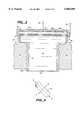
- FIG. 2is a cross-sectional elevational view depicting a microactuator included in the fully implantable hearing aid system depicted in FIG. 1 that is implanted in the promontory of the inner ear, that has a transducer located in the middle ear cavity, and that employs hydraulic coupling between the transducer and a flexible diaphragm for stimulating fluid located within the inner ear of a subject;
- FIG. 3Ais a partially sectioned elevational view of an alternative embodiment fully implantable hearing aid system microactuator
- FIG. 3Bis a cross-sectional elevational view of the microactuator taken along the line 3B--3B in FIG. 3A;
- FIG. 4is a cross-sectional elevational view depicting an alternative embodiment implantable microactuator having a corrugated flexible diaphragm that permits a greater diaphragm displacement;
- FIG. 5is a cross-sectional elevational view depicting an alternative embodiment implantable microactuator having a flexible corrugated tube that permits a greater diaphragm displacement;
- FIG. 6is a plan view of a PVDF (Kynar) sheet illustrating sensitivity axes of the PVDF film
- FIG. 7is a plan view illustrating implantation of a pair of microphones on a subject's head to provide noise cancellation
- FIG. 8Ais a plan view illustrating implantation of a pair of microphones on a subject's head to provide noise cancellation based on the direction from which sound arrives at an earlobe;
- FIG. 8Bin an enlarged plan view illustrating implantation of the microphone on different sides of the subject's earlobe
- FIG. 9is an intensity diagram depicting directional sensitivity of a microphone array
- FIG. 10is a plan view illustrating the microphone array depicted in FIG. 9 implanted on the skull of a subject to provide directional hearing sensitivity;
- FIG. 11is a cross-sectional plan view schematically illustrating sonic or ultrasonic control of an implanted microactuator that is hermetically enclosed in a biologically inert housing;
- FIG. 12is an enlarged cross-sectional plan view depicting a PVDF sheet located within the biologically inert microactuator housing depicted in FIG. 11;
- FIG. 13Ais a plan view depicting a shape for the PVDF sheet suitable for use in a microactuator housing having a circularly-shaped wall;
- FIG. 13Bis an elevational view of the circularly-shaped microactuator depicted in FIG. 13A;
- FIG. 14is a perspective view of a directional booster that a subject, having an implanted hearing aid system, may wear for increasing directivity of sound perceived by the subject;
- FIG. 15is a plan view illustrating the directional booster depicted in FIG. 14 disposed externally on a subject's head.
- FIG. 1illustrates relative locations of components of a fully implantable hearing aid 10 after implantation in a temporal bone 11 of a human subject 12.
- FIG. 1also depicts an external ear 13 located at one end of an external auditory canal 14, commonly identified as the ear canal.
- An opposite end of the external auditory canal 14terminates at an ear drum 15.
- the ear drum 15mechanically vibrates in response to sound waves that travel through the external auditory canal 14.
- the ear drum 15serves as an anatomic barrier between the external auditory canal 14 and a middle ear cavity 16.
- the ear drum 15amplifies sound waves by collecting them in a relatively large area and transmitting them to a much smaller area of an oval-shaped window 19.
- An inner ear 17is located in the medial aspects of the temporal bone 11.
- the inner ear 17is comprised of otic capsule bone containing the semicircular canals for balance and a cochlea 20 for hearing.
- a relatively large bone, referred to as the promontory 18,projects from the otic capsule bone inferior to the oval window 19 which overlies a basal coil of the cochlea 20.
- a round window 29is located on the opposite side of the promontory 18 from the oval window 19, and overlies a basal end of the scala tympani.
- ossicular chain 21Three mobile bones (malleus, incus and stapes), referred to as an ossicular chain 21, span the middle ear cavity 16 to connect the ear drum 15 with the inner ear 17 at the oval window 19.
- the ossicular chain 21conveys mechanical vibrations of the ear drum 15 to the inner ear 17, mechanically de-amplifying the motion by a factor of 2.2 at 1000 Hz.
- Vibrations of a stapes footplate 27 in the oval window 19cause vibrations in perilymph fluid 20a contained in scala vestibuli of the cochlea 20.
- These pressure wave "vibrations"travel through the perilymph fluid 20a and endolymph fluid of the cochlea 20 to produce a traveling wave of the basilar membrane.
- Displacement of the basilar membranebends "cilia" of the receptor cells 20b.
- the shearing effect of the cilia on the receptor cells 20bcauses depolarization of the receptor cells 20b.
- Depolarization of the receptor cells 20bcauses auditory signals to travel in a highly organized manner along auditory nerve fibers 20c, through the brainstem to eventually signal a temporal lobe of a brain of the subject 12 to perceive the vibrations as "sound.”
- the ossicular chain 21is composed of a malleus 22, an incus 23, and a stapes 24.
- the stapes 24is shaped like a "stirrup" with arches 25 and 26 and a stapes footplate 27 which covers the oval window 19.
- the mobile stapes 24is supported in the oval window 19 by an annular ligament which attaches the stapes footplate 27 to the solid otic capsule margins of the oval window 19.
- FIG. 1also illustrates the three major components of the hearing aid 10, a microphone 28, a signal-processing amplifier 30 which includes a battery not separately depicted in FIG. 1, and microactuator 32.
- Miniature cables or flexible printed circuits 33 and 34respectively interconnect the signal-processing amplifier 30 with the microactuator 32, and with the microphone 28.
- the microphone 28is mounted below the skin in the auricle, or alternatively in the postauricular area of the external ear 13 including the lobule 13a, i.e. the earlobe.
- the signal-processing amplifier 30is implanted subcutaneously behind the external ear 13 within a depression 38 surgically sculpted in a mastoid cortical bone 39 of the subject 12.
- the signal-processing amplifier 30receives a signal from the microphone 28 via the miniature cable 33, amplifies and conditions that signal, and then re-transmits the processed signal to the microactuator 32 via the miniature cable 34 implanted below the skin in the external auditory canal 14.
- the signal-processing amplifier 30processes the signal received from the microphone 28 to optimally match characteristics of the processed signal to the microactuator 32 to obtain the desired auditory response.
- the signal-processing amplifier 30may perform signal processing using either digital or analog signal processing, and may employ both nonlinear and highly complex signal processing.
- the microactuator 32transduces the electrical signal received from the signal-processing amplifier 30 into vibrations that either directly or indirectly mechanically vibrate the perilymph fluid 20a in the inner ear 17. As described previously, vibrations in the perilymph fluid 20a actuate the receptor cells 20b to stimulate the auditory nerve fibers 20c which signal the brain of the subject 12 to perceive the mechanical vibrations as sound.
- FIG. 1depicts the relative position of the microphone 28, the signal-processing amplifier 30 and the microactuator 32 with respect to the external ear 13.
- the subject 12may control the operation of the hearing aid 10 using techniques analogous to those presently employed for controlling the operation of miniaturized external hearing aids.
- Both the microphone 28 and the microactuator 32are so minuscule that their implantation requires little or no destruction of the tissue of the subject 12.
- the microphone 28 and the signal-processing amplifier 30do not interfere with the normal conduction of sound through the ear, and thus will not impair hearing when the hearing aid 10 is turned off or not functioning.
- FIG. 2depicts an embodiment of the microactuator 32 described in the PCT Patent Application PCT/US96/15087 that is hereby incorporated by reference.
- the PCT Patent Applicationclaims priority from U.S. patent application Ser. No. 08/532,398 filed Sep. 22, 1995, which issued on Jun. 30, 1998, as U.S. Pat. No. 5,772,575 ("the '575 patent”).
- the '575 patentis hereby incorporated by reference.
- the microactuator 32 illustrated in FIG. 2includes a threaded, metallic tube 42 that screws into a fenestration formed through the promontory 18.
- the fenestrationcan be made by a mechanical surgical drill, or by present surgical laser techniques.
- the portion of the tube 42 threaded into the fenestrationhas a diameter of approximately 1.4 mm.
- the tube 42may be made out of stainless steel or any other biocompatible metal.
- a smaller end 42a of the tube 42is sealed by a metal diaphragm 44, and a second metal diaphragm 46 seals a larger end 42b of the tube 42.
- the larger end 42b of the tube 42can be as large as 2.6 mm.
- the smaller end 42a of the tube 42 together with the diaphragm 44is situated in the inner ear 17 in contact with the perilymph fluid 20a.
- Small capillaries 48pierce the larger end 42b of the tube 42 to permit filling the tube 42 between the diaphragms 44 and 46 completely with an incompressible liquid 52 such as silicone oil, saline fluid, etc.
- the liquid 52must be degassed and free of bubbles so volumetric displacements of the diaphragm 46 are faithfully transmitted to the diaphragm 44. This is done by evacuating the tube 42 and backfilling it through the small capillaries 48.
- the capillaries 48if made of stainless steel, titanium or other suitable biocompatible material, may be sealed with pulsed laser welding which produces an instantaneous seal without bubbles. Alternatively, small copper capillaries 48 may be used for backfilling and then pinched off.
- a stress-biased PLZT disk-shaped transducer 54is conductively attached to the diaphragm 46 and to the larger end 42b of the tube 42. Alternatively, the transducer 54 may be made small enough to rest entirely on diaphragm 46.
- a conductive cermet layer 54b of the transducer 54is juxtaposed with the metal diaphragm 46.
- the tube 42, the diaphragm 46 and conductive cermet layer 54bare preferably grounded through an electrical lead 55 included in the miniature cable 34.
- a PLZT layer 54a of the transducer 54is coated with a conductive layer 54c of gold or any other suitable biocompatible material.
- An electrical lead 56included in the miniature cable 34, is attached to the conductive layer 54c either through wire bonding or with conductive epoxy.
- a thin conformal layer 58 of a coating materialcovers the larger end 42b and the transducer 54 to encapsulate the transducer 54.
- the volume displacement of transducer 54increases as the fourth power of transducer diameter, for a pre-established voltage applied across the transducer 54 the volume of displaced liquid 52, which is the significant characteristic for a hearing aid, is sixteen (16) times larger, than if a transducer of the same diameter as diaphragm 44 were placed in the location of diaphragm 44.
- the microactuator 32may actually include two disk-shaped transducers 54 for increasing deflection of the diaphragm 44.
- the arrangement of the diaphragms 44 and 46 depicted FIG. 2provides a mechanical impedance match for the transducer 54.
- the displacement amplification provided by the liquid 52acts as the impedance transformer, and does so all the way into the audio range frequency. Consequently, the microactuator 32 depicted in FIG. 1 matches the characteristics of the transducer 54 to the characteristics desired for the hearing aid 10.
- the impedance match provided hereis a large deflection of the diaphragm 44 desired in the inner ear 17, constrained by a limited driving voltage applied across the transducer 54, and a limited fenestration diameter provided by the promontory 18 and the cochlea 20.
- Other mechanical impedance matching devicessuch as levers
- the fluid-filled microactuator 32provides for extremely smooth and powerful motion.
- larger end 42b of the tube 42 from the PCT Patent Application depicted in FIG. 1 located in the middle ear cavity 16need not be limited to a rounded shape. Rather, as described in greater detail below the shape of the larger end 42b may preferably be formed so it confoms much better anatomically to the shape of the inner ear cavity (e.g. the larger end 42b is elongated) which also permits better anchoring of the microactuator 32 to promontory 18. Such a shape for the larger end 42b permits enlarging the surface area of the transducer 54 which increases its deflection and displacement.
- FIGS. 3A and 3Bdepict an alternative embodiment of the microactuator 32 which provides a large displacement of the diaphragm 44 in response to application of a smaller voltage across the transducer.
- Those elements depicted in FIGS. 3A and 3B that are common to the microactuator 32 depicted in FIG. 2carry the same reference numeral distinguished by a prime ("'") designation.
- the microactuator 32'includes a hollow body 62 from one end of which projects a cylindrically-shaped, flanged nozzle 63.
- the flanged nozzle 63which is adapted for insertion into a fenestration formed through the promontory 18, has an open first end 64.
- the first end 64is sealed by the flexible diaphragm 44' that may be deflected outward from and inward toward the body 62.
- the body 62has two open faces 66a and 66b that are separated from the first end 64.
- Each of the faces 66a and 66bare respectively sealed by flexible diaphragms 46a and 46b which, in combination with the diaphragm 44', hermetically seal the body 62.
- each of the diaphragms 46a and 46bare oriented in a direction that is not parallel to the diaphragm 44'. As depicted in FIGS.
- the diaphragms 46a and 46brespectively have cross-sectional areas that are larger than a cross-sectional area of the diaphragm 44'. While the preceding description of the body 62 identifies various individual parts thereof, the body 62 may, in fact, be provided by a one-piece can formed from a material suitable for the diaphragms 46a and 46b.
- the hermetically sealed hollow body 62is filled with the incompressible liquid 52'.
- Respectively secured to each of the diaphragms 46a and 46bare plates 68 of piezoelectric material which face each other.
- Anatomical considerationspermit the plates 68 to extend a considerable distance into the middle ear cavity 16, and also permit shapes for the body 62 and the plates 68 that differ from those depicted in FIGS. 3A and 3B.
- the base of the body 62 adjacent to the flanged nozzle 63can be very narrow and the length of the body 62 and plates 68 extending outward from the flanged nozzle 63 enlarged so that the volume of the liquid 52' displaced by the plates 68 becomes quite large. In this way the plates 68 can be shaped, twisted and tilted to fit the middle ear cavity 16, and are not restricted to the space locally available at the implantation site.
- Each of the plates 68are electrically connected to the miniature cable 34' to expand or contract in opposite direction toward or away from each other in response to the same applied voltage.
- This driving motion of the plates 68 applied to the diaphragms 46a and 46bforces the liquid 52 toward or away from the diaphragm 44' that is located in the inner ear 17 of the subject 12.
- application of an electric signal from the signal-processing amplifier 30 to the plates 68directly deflects the diaphragms 46a and 46b. Deflection of the diaphragms 46a and 46b is coupled by the liquid 52' to deflect the diaphragm 44'.
- the microactuator 32'preferably employs a pair of plates 68, a microactuator 32' in accordance with the present invention may have only a single plate 68, or each plate 68 of the pair may have a different shape and/or size.
- FIGS. 3A and 3Bdepicts the diaphragms 46a and 46b as being oriented perpendicular to the diaphragm 44' with the diaphragms 46a and 46b parallel to each other, other orientations of the diaphragms 46a and 46b with the respect to the diaphragm 44' are within the scope of the invention. Accordingly, the diaphragms 46a and 46b can be oriented at a skewed angle with respect to the flanged nozzle 63 and diaphragm 44' to prevent the plates 68 from interfering with the ossicular chain 21 or other structures.
- the flanged nozzle 63provides good anchoring to the promontory 18 without requiring extra room which would otherwise reduce space available for the plates 68.
- microactuator 32'may be held in place with an array of stainless or titanium pins and/or barbs projecting around the periphery of the flanged nozzle 63 as described in the PCT Patent Application. In that way, the microactuator 32' need not be turned or twisted during implantation into the fenestration through the promontory 18. Alternatively, the microactuator 32' may be secured with a small, memory alloy expanding stent such as those used to hold arteries open following cardiac surgery.
- deflections of the diaphragm 44 or 44'are very small (only on the order of a micron), and the driving voltage applied across the transducer 54 or the plates 68 is very low. Consequently, in the fully implantable hearing aid system a flat diaphragm 44 or 44' can be used.
- other applications for the microactuator 32such as in implantable pumps, valves, or for other types of battery energized biological stimulation, may require a greater displacement for the diaphragm 44 or 44', a larger disk-shaped transducer 54, and/or a higher driving voltage. As illustrated in FIG.
- the flat diaphragm 44 or 44' depicted in FIGS. 2, 3A and 3Bmay be replaced by a bellows diaphragm 82 having circularly-shaped corrugations 84.
- Those elements depicted in FIG. 4 that are common to the microactuator 32 depicted in FIG. 2carry the same reference numeral distinguished by a double prime (""") designation.
- the corrugated bellows diaphragm 82can provide much larger displacements as desired.
- the bellows diaphragm 82may be much thicker than the diaphragm 44 or 44' because the corrugations 84 increase the flexibility of the bellows diaphragm 82.
- the ratio of the area of the transducer 54 to the actual area of the bellows diaphragm 82can be much larger than four (4) if desired, and hence quite large displacements of the bellows diaphragm 82 become possible.
- a transducer 54that has an area of one-quarter inch, that is 200 microns thick, and that receives a 200 volt ("V") driving signal
- V200 volt
- the displacement of the bellows diaphragm 82may approach 1.0 mm.
- Such high driving signal voltagescan be readily generated from battery voltages using a flyback circuit, since the transducer 54 requires virtually no electrical power for its operation.
- FIG. 5depicts yet another alternative embodiment microactuator 32 in which a portion of the tube 42 is replaced by a bellows 92 that includes encircling corrugations 94.
- Those elements depicted in FIG. 4 that are common to the microactuator 32 depicted in FIG. 2carry the same reference numeral distinguished by a triple prime ("'"") designation.
- the corrugations 94which upon implantation into the subject 12 should not be anchored to permit free movement of a moving surface 96, provide large displacements of the surface 96.
- the microactuator 32" or 32'"are suitable for inclusion in a fully implantable hearing aid system, such as that depicted in FIG. 1, in which the microactuator 32 implanted into a fenestration formed through the promontory 18 is replaced by the microactuator 32" or 32'" depicted respectively in FIGS. 4 and 5 with the microactuator 32" or 32'” being pressed gently into contact with the round window 29 of the inner ear 17.
- the liquid 52" or 52'"provides an impedance match for the disk-shaped transducer 54" or 54'” allowing the large force produced by the transducer 54" or 54'" to be transformed in a larger displacement of the bellows diaphragm 82 or the surface 96.
- microactuator 32" or 32'may still apply a force on the order of several grams to deflect the round window 29.
- micromachined barbs 98 having a stop 102may encircle the tube 42 for anchoring the microactuator 32" or 32'" within the middle ear cavity 16.
- the area of the transducer 54, 54', 54" or 54'"may be smaller than the area of the diaphragm 44, 44', bellows diaphragm 82 or surface 96 thereby producing a larger force but a reduced deflection or displacement of the diaphragm 44, 44', bellows diaphragm 82 or surface 96.
- the PCT Patent Applicationdescribes the disk-shaped transducer 54 as being preferably fabricated from a stress-biased PLZT material manufactured by Aura Ceramics and sold under the "Rainbow" product designation.
- differential thermal expansionalso permits producing a stress-biased piezoelectric material. That is, a disk of PZT or PLZT ceramic material may be coated at high temperature with a metal foil that is approximately one-third (1/3) the thickness of the ceramic material. This metal coated, piezoelectric ceramic material structure then becomes stress-biased when cooled to room temperature.
- Metals suitable for coating PZT or PLZT ceramic materialinclude titanium, nickel, titanium-nickel alloys, stainless steel, brass, platinum, gold, silver, etc.
- Conventional PZT unimorph or bimorph structuresmay also be used.
- the best of such conventional piezoelectric ceramic materials for the transducer 54, 54', 54" or 54'", or for the plates 68appear to be those in the class called Navy type VI.
- Such materialsinclude the PTZ5H and C3900 materials manufactured by Aura Ceramics, and in particular the 3203, 3199 or 3211 manufactured by Motorola, Inc.
- Suitable piezoelectric ceramic materialssuch as those listed above all exhibit high values of the d 31 material parameter, and can be lapped to an appropriate thickness such as 75 microns.
- Such conventional piezoelectric materialsare particularly suitable for use in the hearing aid microactuator 32' depicted in FIGS. 3A and 3B.
- the preferred embodiment of the microphone 28 illustrated in FIG. 1consists of a very thin sheet of polyvinylidenefluoride (“PVDF”) having an area of approximately 0.5 to 2.0 square centimeter (“cm 2 ”) that has bio-compatible metallic electrodes coated onto its surface. As illustrated in FIG. 1, the microphone 28 may be implanted into the lobule 13a of the external ear 13. PVDF material suitable for the microphone 28 is identified commercially by a trademark KYNAR that is registered to AMPS Corporation.
- PVDFpolyvinylidenefluoride
- a sheet 112 of Kynaris stretched and polarized along an axis (a--a) to produce a permanent dipole in the material.
- stretching of the sheet 112for example due to acoustic vibration of the supporting body, produces electric charges on the surface of the sheet 112.
- Stretching or compressing the Kynar sheet 112 along the axis (a--a)produces large output signals.
- stretching or compressing the Kynar sheet 112 along an axis (b--b), that is perpendicular to the axis (a--a)produces signals which are only one-tenth (1/10) of those produced by stretching along the axis (a--a).
- these properties of the Kynar sheet 112may be used advantageously to improve directivity of the microphone 28.
- Kynar microphone 28has virtually the same sensitivity when located outside of the body or when implanted subcutaneously.
- FIG. 7is a plan view of a head 122 of the subject 12 into which a hearing aid system has been implanted.
- the first microphone 28 described in the PCT Patent Applicationis implanted in the lobule 13a of the external ear 13 at a location (a) in FIG. 7. Because the Kynar microphone 28 is thin and unobtrusive, as illustrated in FIG. 7, a second microphone 28 (or more if desired) may be implanted at a different location (b) on the head 122 of the subject 12.
- the second microphone 28 at location (b)serves as a general reference point for background noise.
- the second microphone 28is less likely to be exposed to sounds of interest, or at least the intensity of the sound of interest is less at the location (b) than at the location (a) of the first microphone 28.
- the second microphone 28 at location (b)therefore preferentially picks up background noise in the environment, which often is more omnidirectional, having, in most instances, reverberated from a number of surfaces.
- FIG. 8Aillustrates a second way of implementing noise cancellation which depicts the lobule 13a of the external ear 13 projecting from the head 122 of the subject 12.
- FIG. 8Adepicts the lobule 13a of the external ear 13 as a plate sticking out from the head 122.
- the first microphone 28is implanted either at location (a) or (a') depicted in FIG. 8B with the second microphone 28 being implanted nearby at a location (b) on the head 122 of the subject 12.
- the lobule 13a of the external ear 13responds to impingement of acoustic waves by bending ever so slightly.
- the second Kynar microphone 28 at location (b)responds very much the same because the surrounding tissues compress the same regardless of sound direction. Conversely, the first Kynar microphone 28 at location (a) or (a') produces an electrical signal that also includes bending of the lobule 13a. Note that implanting the first microphone 28 either at location (a) or (a') reverses the polarity of the signal due to the direction of lobe bending.
- the signal-processing amplifier 30can sum the signal from the two microphones 28 for sound coming from in front of the head 122, while canceling sound coming from behind the head 122.
- Such an operating modemay be highly desirable during conversation to eliminate at least part of the background noise.
- the Kynar microphone 28must be positioned on the lobule 13a of the external ear 13 so it responds differently to sound waves arriving from in front of the head 122 or from behind the malleus 22.
- the microphone 28Since the directivity of this second noise cancellation technique results from bending the Kynar microphone 28, the microphone 28 must therefore be implanted so the (a--a ⁇ axis gets stretched or compressed significantly by the bending of the lobule 13a. Conversely, the Kynar microphone 28 should be oriented to minimize bending along the axis (b--b).
- the subject 12may further enhance this noise cancellation by turning the head 122 to position the external ear 13 for optimum reception of sounds of interest, i.e. to enhance the discrimination between the two signals.
- the subtraction of the signalsmust be done carefully, or, for example, be restricted to one ear. If the subject 12 surrounded on all sides by noise reverberating from multiple surfaces, this second noise cancellation technique could provide almost complete cancellation of the sound. Under such circumstances, the subject 12 would be unaware of the ambient sound level, which, in some cases, may be hazardous. Consequently, it may be desirable to make noise cancellation using this second technique an optional feature at the control of the subject 12. For example, under some circumstances the subject 12 may want either to remove the subtraction of the signal of the second microphone 28, or reverse the polarity of the signal received from the first microphone 28.
- Implantation of the microphone 28insignificantly affects the phase relationship of signals received by the Kynar microphone 28. Accordingly an advantage of this second technique is that the subject 12 can first be custom outfitted with several sample microphones 28 placed in different locations on the surface of the lobule 13a while trying various different signal processing strategies with the signal-processing amplifier 30 before implanting the first microphone 28.
- FIGS. 9 and 10illustrate a third way of implementing the function of noise cancellation in which an elongated strip of Kynar can provide a distributed microphone.
- Each location at which a bio-compatible metallic electrode overlays the Kynar sheet 112constitutes an active microphone 28.
- the bio-compatible metallic electrodes applied to the sheet 112may be easily patterned to form an array 132 of discrete separate microphones 28.
- An appropriately adapted signal-processing amplifier 30then sums the signals from the microphones 28, applying appropriate weighing factors to the signal from each microphone 28, to obtain a desired characteristic sensitivity pattern from the array 132.
- the hearing aid 10can provide the subject 12 with directivity which the subject 12 may use to enhance the sounds of interest while concurrently reducing noise.
- the wavelength of sound in airis only 6.8 cm.
- Providing a directional array that is one-half wavelength long at 5000 Hzrequires that the array 132 be only a few centimeters long.
- Output signals from each of the microphones 28 of the array 132are then coupled through the miniature cable 33 to the signal-processing amplifier 30.
- the signal-processing amplifier 30appropriately weighs the output signals from each of the microphones 28 with a cosine distribution to obtain the pattern c depicted in FIG. 9 over the length of the array 132.
- Implanting the array 132 on the head 122 of the subject 12 around the external ear 13 as depicted in FIG. 9provides a directional sound receiving pattern as illustrated by a radiation pattern b depicted in FIG. 9.
- the subject 12may use the radiation pattern b to advantage to improve reception of such sounds, and to reject noise.
- the array 132 of microphones 28 described thus farmore complex super radiant array structures may be employed in the hearing aid 10.
- Kynar microphones 28 implanted on the subject 12may be used advantageously to provide noise cancellation and/or microphone directivity. Any of the preceding microphone implantation techniques can be used with frequency filtration techniques to further enhance sound perceived by the subject 12. While the preferred embodiment of the invention uses Kynar microphones 28, in principle two or more suitable implantable microfabricated microphones may be used in implementing any of the techniques described above. However, the Kynar microphones 28 are preferred because they are extremely small, thin, unobtrusive and rugged, readily patterned into arrays as described, and are low cost.
- microactuator 32, 32" and 32'such as in implantable pumps, valves, or for other types of battery energized biological stimulation.
- the PCT Patent Applicationdescribes how signals, perhaps at ultrasonic frequencies, can be used to provide volume or frequency response control for the implantable hearing aid 10.
- This control techniquecan be readily generalized for use with other implantable microactuators 32 where it is desirable to change operating parameters after implantation. After implantation, very often it may be advantageous to change the stroke, or the stroke frequency or period of the microactuator 32, 32" or 32'".
- Using a Kynar microphone 28 as an acoustic pick upprovides a very inexpensive method for effecting such control.
- FIG. 11schematically illustrates a typical arrangement of the microactuator 32, 32 or 32'", e.g. a pump, valve etc., implanted within a body 142, or a body limb, of the subject 12.
- a biologically inert or biocompatible housing 144hermetically encloses the microactuator 32, 32" or 32'" together with a battery and control electronics 146.
- An external ultrasonic or acoustic transmitter 148touches the body 142, possibly with fluid or grease coupling between the transmitter 148 and the skin.
- the transmitter 148sends out a sequence of ultrasonic or acoustic pulses, indicated by wavy lines 152 in FIG. 12, which may be preprogrammed in electronics included within the transmitter 148.
- a receiving transducer 154located within the housing 144 as depicted in FIG. 12, receives the sequence of pulses.
- An electronic circuit or microprocessor computer program included in the battery and control electronics 146interprets the sequence of pulses as a command string to change the setting of the microactuator 32, 32" or 32'".
- the receiving transducer 154preferably consisting of a Kynar strip, is attached to a wall 156 of the housing 144.
- Ultrasonic pulses impinging upon the wall 156deform and stress the Kynar receiving transducer 154 thereby generating electrical signals. After suitable amplification and processing, these electrical signals represent digital commands for controlling the operation of the microactuator 32, 32", or 32'".
- FIGS. 13A and 13Billustrate a shape for the Kynar receiving transducer 154 adapted for attachment to a circularly-shaped wall 156 of the housing 144.
- Both sides of the Kynar sheetwhich is typically between 8 to 50 microns thick, are overcoated with thin metal electrodes 158a and 158b.
- the overlapping area of the metal electrodes 158a and 158bdefines an active area of the Kynar receiving transducer 154.
- the metal electrodes 158a and 158bmay be fabricated from biocompatible materials such as gold, platinum, titanium etc. that are applied by vacuum deposition, sputtering, plating, or silk screening.
- the metal electrodes 158a and 158bmay be supported on the PVDF sheet by an underlying thin layer of an adhesive material such as nickel or chromium. Since Kynar is very inert, in principle the receiving transducer 154 having biocompatible electrodes may be used even on the outside of the housing 144.
- Control datamay be transferred from the transmitter 148 to the battery and control electronics 146 in modem like fashion using, for example, frequency shift keying in which one frequency is recognized as a one, while a different frequency is recognized as a zero.
- the carrier frequency of pulses transmitted by the transmitter 148should preferably be above audio frequencies, in the ultrasonic range of 25 kHz to 45 MHz, and can be tailored to the particular depth or location of the implanted microactuator 32, 32" or 32'" to avoid echoes in the body. The higher the carrier frequency, the better the directivity of the transmitter 148, but the detecting electronics will then need to run at a higher clock frequency which increases the power dissipation.
- a series of control pulsesmay be sent to the electronics within the housing 144, which the electronics interprets to alter the present operating mode for the microactuator 32, 32" or 32'", e.g. shutdown or activation, change the stroke or periodicity of the actuator (e.g. by changing the drive voltage accordingly, or by changing the period of the stroke etc.).
- the threshold for control pulse detectionmay be very high since normal sound waves in air bounce off body 142 without transmission. Only if the sound or ultrasound is effectively coupled into the body 142 by contact between the body 142 and the transmitter 148 having a well matched ultrasonic transducer will the receiving transducer 154 receive the pulses.
- This method for controlling operation of the microactuator 32, 32" or 32'"therefore, is quite immune to spurious commands or noise which is very desirable for life critical, implantable devices.
- the piezoelectric disk-shaped transducer 54, 54" or 54'" included in the microactuator 32, 32" or 32'”could also serve as the receiving transducer 154 at least in the lower ultrasonic range.
- the control pulse receiving circuitryneeds to be strongly decoupled from the transducer driving circuitry, that may supply high voltage driving electric signals to the transducer 54, 54" or 54'". Therefore, a separate inexpensive and rugged transducer such as the Kynar receiving transducer 154 is generally preferred.
- a photo-voltaic cell 162may also be implanted subdermally and connected by a miniature cable or flexible printed circuit 164 to the battery and control electronics 146 located within the housing 144.
- the photo-voltaic cell 162is fastened to the housing 144, thereby preferably establishing one of the two electrical connections to the photo-voltaic cell 162.
- the miniature cable or flexible printed circuit 164need only include a single electrical conductor.
- the photo-voltaic cell 162can be fabricated using amorphous silicon which permits forming the photo-voltaic cell 162 on various different substrates such as the housing 144, and even on a flexible substrate.
- the photo-voltaic cell 162may be suitably overcoated so that after implantation its presence beneath the skin is not readily observable. Located immediately beneath the skin, sufficient ambient light, indicated in FIG. 11 by a Z-shaped arrow 166, impinges upon the photo-voltaic cell 162 that electrical power produced by the photo-voltaic cell 162 is sufficient for energizing the operation of the microactuator 32, 32" or 32'". As illustrated in FIG. 1, the hearing aid 10 may also include a subdermally implanted photo-voltaic cell 172 that is coupled by a miniature cable or flexible printed circuit 174 to the signal-processing amplifier 30. In the embodiment depicted in FIG. 1, the photo-voltaic cell 172 supplies energy for operating the hearing aid 10.
- directional booster 200depicted there is a directional booster, referred to in FIG. 14 by the general reference character 200, that the subject 12 may wear on their head 122 for increasing directivity of sound perceived by the subject 12.
- directional booster 200is depicted as being incorporated into eyeglasses 202. While the eyeglasses 202 may be suitable appliance for supporting the directional booster 200 on the head 122 of the subject 12, other appliances such as a cap, hat or helmet may also be used for that same purpose.
- the directional booster 200includes an array 204 of microphones 28 fastened to a bridge 206 of the eyeglasses 202. Similar to the array 132 depicted in FIGS. 9 and 10, each microphone 28 included in the array 204 independently generates an electrical signal in response to sound waves impinging upon the subject 12.
- the array 204may be fabricated from Kynar in the same manner as the array 132, or may be a microfabricated microphone.
- a battery 212 for energizing operation of the directional booster 200 and a signal processing circuit 214are embedded within or fastened to one of a pair of skull temples 216 included in the eyeglasses 202. Similar to the array 132 depicted in FIGS.
- the signal processing circuit 214sums the signals from the microphones 28 of the array 204, applying appropriate weighing factors to the signal from each microphone 28, to obtain a desired characteristic sensitivity pattern from the array 204 similar to that depicted in FIG. 10.
- the signal processing circuit 214includes controls similar to those used in conventional hearing aids such as a volume control, etc.
- the signal processing circuit 214supplies the processed electrical signal obtained in this way as an excitation signal to a booster transducer 222 carried in or fastened to an end piece 224 of the skull temple 216.
- the booster transducer 222may be a piezoelectric transducer similar to the transducer 54, 54" or 54'" respectively included in the microactuator 32, 32" or 32'", the plates 68 included in the microactuator 32', or a ceramic speaker such as those used in some cellular telephones.
- the booster transducer 222may be an electromagnetic transducer, a speaker such as those used in conventional hearing aids, or any other type of transducer that converts an electrical signal into mechanical vibrations.
- the booster transducer 222Responsive to the excitation signal received from the signal processing circuit 214, the booster transducer 222 generates mechanical vibrations.
- the end piece 224 of the eyeglasses 202urges the booster transducer 222 into intimate contact with the head 122 of the subject 12 whereby the vibrations, generated by the booster transducer 222, are coupled to the head 122. If, as illustrated in FIG. 15, the end piece 224 urges the booster transducer 222 into intimate contact with the head 122 at a location immediately adjacent to or over the microphone 28 included in the hearing aid 10, then the vibrations produced by the booster transducer 222 are coupled directly into the microphone 28.
- the directional booster 200provides the subject 12 with directivity which the subject 12 may use to enhance the sounds of interest.
- the directional booster 200preferably exhibits greatest sensitivity directly in front of the subject 12. Accordingly, if the subject 12 wears the directional booster 200 on a social occasion the direction of greatest sensitivity is toward whoever the subject faces rather than at a right angle to such an individual.
- the array 204, the battery 212, the signal processing circuit 214 and the booster transducer 222are all preferably supported on the head 122 of the subject 12 by an appliance such as the eyeglasses 202, a cap, hat, or helmet; in principle the battery 212 and the signal processing circuit 214, or the entire directional booster 200, could be located anywhere else on the subject 12. Similar to the photo-voltaic cell 162 depicted in FIGS. 11 and 12, and to the photo-voltaic cell 172 depicted in FIG. 1; a photo-voltaic cell 232, coupled to the signal processing circuit 214 and preferably located in the skull temple 216, may be included in the directional booster 200 to supply electrical energy for its operation.
- the arrangements for the microactuator 32" or 32'", respectively depicted in FIGS. 4 and 5,may greatly extend the range of the actuator stroke which is often very desirable.
- the impedance matching characteristicis particularly suitable for piezoelectric transducer 54" and 54'", because these units have such a large force as compared to other piezoelectric devices providing the same displacement. Because of the very large forces developed, particularly with stress-biased PLZT structures, the force at the bellows diaphragm 82 or surface 96, which is decreased in the same way as the stroke is enlarged, can still be very large, in the order of tens of grams or higher.
- Such a mechanismmay be used as a pump piston, with a one way valve, as a valve controlling mechanism or in a variety of other ways.
- the fluidic arrangementalso spreads out the load over the surface of the transducer 54" and 54'", which is highly desirable as compared to point loading.
- This fluidic impedance matching arrangementcan of course also be very advantageously used in other microactuators, which are not implanted.
- FIGS. 2, 4 and 5also provide for isolation of non-biocompatible parts of the microactuator 32, 32" and 32'". If no impedance matching is required, then arrangements of the transducer 54 depicted in the PCT Patent Application may be used.
- the disk-shaped piezoelectric transduceris conductively attached to a very thin bio-compatible metal diaphragm, which is hermetically sealed to can 4 by e-beam or laser beam welding.
- the thin diaphragmallows for the full deflection of the piezoelectric transducer with the edge of the diaphragm functioning as a hinge.
- a pair of piezoelectric transducersare juxtaposed and urged into contact with the diaphragm by sleeve which might also function as an electrical lead.
- juxtaposition of two piezoelectric transducersdoubles the displacement for the same voltage applied across the pair of transducers.
- a second piezoelectric transducerthat is backed by a suitable support structure such as those disclosed in the PCT Patent Application, can be added to each transducer 54, 54" or 54'" or plates 68 to double their respective displacement(s).
Landscapes
- Health & Medical Sciences (AREA)
- General Health & Medical Sciences (AREA)
- Otolaryngology (AREA)
- Physics & Mathematics (AREA)
- Engineering & Computer Science (AREA)
- Acoustics & Sound (AREA)
- Signal Processing (AREA)
- Neurosurgery (AREA)
- Prostheses (AREA)
- Materials For Medical Uses (AREA)
Abstract
Description
Claims (22)
Priority Applications (2)
| Application Number | Priority Date | Filing Date | Title |
|---|---|---|---|
| US08/801,056US6068589A (en) | 1996-02-15 | 1997-02-14 | Biocompatible fully implantable hearing aid transducers |
| US10/274,391US20030055311A1 (en) | 1996-02-15 | 2002-10-18 | Biocompatible transducers |
Applications Claiming Priority (3)
| Application Number | Priority Date | Filing Date | Title |
|---|---|---|---|
| US1169196P | 1996-02-15 | 1996-02-15 | |
| US1188296P | 1996-02-20 | 1996-02-20 | |
| US08/801,056US6068589A (en) | 1996-02-15 | 1997-02-14 | Biocompatible fully implantable hearing aid transducers |
Related Child Applications (1)
| Application Number | Title | Priority Date | Filing Date |
|---|---|---|---|
| US46590899ADivision | 1996-02-15 | 1999-12-17 |
Publications (1)
| Publication Number | Publication Date |
|---|---|
| US6068589Atrue US6068589A (en) | 2000-05-30 |
Family
ID=26682683
Family Applications (2)
| Application Number | Title | Priority Date | Filing Date |
|---|---|---|---|
| US08/801,056Expired - LifetimeUS6068589A (en) | 1996-02-15 | 1997-02-14 | Biocompatible fully implantable hearing aid transducers |
| US10/274,391AbandonedUS20030055311A1 (en) | 1996-02-15 | 2002-10-18 | Biocompatible transducers |
Family Applications After (1)
| Application Number | Title | Priority Date | Filing Date |
|---|---|---|---|
| US10/274,391AbandonedUS20030055311A1 (en) | 1996-02-15 | 2002-10-18 | Biocompatible transducers |
Country Status (8)
| Country | Link |
|---|---|
| US (2) | US6068589A (en) |
| EP (1) | EP0880870B1 (en) |
| JP (1) | JP2000504913A (en) |
| KR (1) | KR19990082641A (en) |
| CN (1) | CN1216208A (en) |
| AU (1) | AU710983B2 (en) |
| DE (1) | DE69738884D1 (en) |
| WO (1) | WO1997030565A1 (en) |
Cited By (125)
| Publication number | Priority date | Publication date | Assignee | Title |
|---|---|---|---|---|
| DE10046938A1 (en)* | 2000-09-21 | 2002-04-25 | Implex Ag Hearing Technology I | At least partially implantable hearing system with direct mechanical stimulation of a lymphatic space in the inner ear |
| US6381336B1 (en)* | 1996-05-24 | 2002-04-30 | S. George Lesinski | Microphones for an implatable hearing aid |
| US20020115920A1 (en)* | 2001-01-22 | 2002-08-22 | Rich Collin A. | MEMS capacitive sensor for physiologic parameter measurement |
| US6554761B1 (en)* | 1999-10-29 | 2003-04-29 | Soundport Corporation | Flextensional microphones for implantable hearing devices |
| US6554762B2 (en)* | 2000-08-25 | 2003-04-29 | Cochlear Limited | Implantable hearing system with means for measuring its coupling quality |
| US20030083713A1 (en)* | 2001-10-29 | 2003-05-01 | Surekha Palreddy | Cardiac rhythm management system with noise detector |
| US6575894B2 (en)* | 2000-04-13 | 2003-06-10 | Cochlear Limited | At least partially implantable system for rehabilitation of a hearing disorder |
| US20030138116A1 (en)* | 2000-05-10 | 2003-07-24 | Jones Douglas L. | Interference suppression techniques |
| WO2002089525A3 (en)* | 2001-04-27 | 2003-10-30 | Univ Virginia Commonwealth | Hearing device improvements using modulation techniques |
| US20040030256A1 (en)* | 2002-08-06 | 2004-02-12 | Yayun Lin | Cardiac rhythm management systems and methods for detecting or validating cardiac beats in the presence of noise |
| US6714654B2 (en) | 2002-02-06 | 2004-03-30 | George Jay Lichtblau | Hearing aid operative to cancel sounds propagating through the hearing aid case |
| US20040106957A1 (en)* | 2001-10-29 | 2004-06-03 | Surekha Palreddy | Method and system for noise measurement in an implantable cardiac device |
| US20040202339A1 (en)* | 2003-04-09 | 2004-10-14 | O'brien, William D. | Intrabody communication with ultrasound |
| US20050157895A1 (en)* | 2004-01-16 | 2005-07-21 | Lichtblau George J. | Hearing aid having acoustical feedback protection |
| US20050218052A1 (en)* | 2004-04-06 | 2005-10-06 | Houts Christina M | Abient noise power generator |
| US6978159B2 (en) | 1996-06-19 | 2005-12-20 | Board Of Trustees Of The University Of Illinois | Binaural signal processing using multiple acoustic sensors and digital filtering |
| US6984207B1 (en)* | 1999-09-14 | 2006-01-10 | Hoana Medical, Inc. | Passive physiological monitoring (P2M) system |
| US6987856B1 (en) | 1996-06-19 | 2006-01-17 | Board Of Trustees Of The University Of Illinois | Binaural signal processing techniques |
| US20060115103A1 (en)* | 2003-04-09 | 2006-06-01 | Feng Albert S | Systems and methods for interference-suppression with directional sensing patterns |
| US20060149329A1 (en)* | 2004-11-24 | 2006-07-06 | Abraham Penner | Implantable medical device with integrated acoustic |
| US20060161255A1 (en)* | 2002-12-30 | 2006-07-20 | Andrej Zarowski | Implantable hearing system |
| US20060188115A1 (en)* | 2001-04-27 | 2006-08-24 | Martin Lenhardt | Hearing device improvements using modulation techniques |
| WO2006088410A1 (en)* | 2005-02-21 | 2006-08-24 | Entific Medical Systems Ab | Vibrator |
| US20060189841A1 (en)* | 2004-10-12 | 2006-08-24 | Vincent Pluvinage | Systems and methods for photo-mechanical hearing transduction |
| US20060251278A1 (en)* | 2005-05-03 | 2006-11-09 | Rodney Perkins And Associates | Hearing system having improved high frequency response |
| US20070014419A1 (en)* | 2003-12-01 | 2007-01-18 | Dynamic Hearing Pty Ltd. | Method and apparatus for producing adaptive directional signals |
| US20070049977A1 (en)* | 2005-08-26 | 2007-03-01 | Cardiac Pacemakers, Inc. | Broadband acoustic sensor for an implantable medical device |
| US7206423B1 (en) | 2000-05-10 | 2007-04-17 | Board Of Trustees Of University Of Illinois | Intrabody communication for a hearing aid |
| US20080021509A1 (en)* | 2006-07-21 | 2008-01-24 | Cardiac Pacemakers, Inc. | Ultrasonic transducer for a metallic cavity implated medical device |
| US20080021289A1 (en)* | 2005-08-26 | 2008-01-24 | Cardiac Pacemakers, Inc. | Acoustic communication transducer in implantable medical device header |
| US20080021510A1 (en)* | 2006-07-21 | 2008-01-24 | Cardiac Pacemakers, Inc. | Resonant structures for implantable devices |
| WO2008077943A3 (en)* | 2006-12-26 | 2008-09-12 | 3Win N V | Device and method for improving hearing |
| US20080307668A1 (en)* | 2007-06-15 | 2008-12-18 | Sidney Watterodt | Methods and devices for drying coated stents |
| US20080312720A1 (en)* | 2007-06-14 | 2008-12-18 | Tran Binh C | Multi-element acoustic recharging system |
| US20090074220A1 (en)* | 2007-08-14 | 2009-03-19 | Insound Medical, Inc. | Combined microphone and receiver assembly for extended wear canal hearing devices |
| US7512448B2 (en) | 2003-01-10 | 2009-03-31 | Phonak Ag | Electrode placement for wireless intrabody communication between components of a hearing system |
| US20090092271A1 (en)* | 2007-10-04 | 2009-04-09 | Earlens Corporation | Energy Delivery and Microphone Placement Methods for Improved Comfort in an Open Canal Hearing Aid |
| WO2009049320A1 (en) | 2007-10-12 | 2009-04-16 | Earlens Corporation | Multifunction system and method for integrated hearing and communiction with noise cancellation and feedback management |
| US7522962B1 (en) | 2004-12-03 | 2009-04-21 | Remon Medical Technologies, Ltd | Implantable medical device with integrated acoustic transducer |
| US20090161895A1 (en)* | 2007-12-19 | 2009-06-25 | Eric Hruza | Sound provider adapted to cancel out noise |
| US20090312820A1 (en)* | 2008-06-02 | 2009-12-17 | University Of Washington | Enhanced signal processing for cochlear implants |
| US20100042184A1 (en)* | 2008-08-13 | 2010-02-18 | Daglow Terry D | Method of implanting a medical implant to treat hearing loss in a patient, devices for faciliting implantation of such devices, and medical implants for treating hearing loss |
| US7666151B2 (en) | 2002-11-20 | 2010-02-23 | Hoana Medical, Inc. | Devices and methods for passive patient monitoring |
| US20100048982A1 (en)* | 2008-06-17 | 2010-02-25 | Earlens Corporation | Optical Electro-Mechanical Hearing Devices With Separate Power and Signal Components |
| US20100046775A1 (en)* | 2008-05-09 | 2010-02-25 | Andreas Tiefenau | Method for operating a hearing apparatus with directional effect and an associated hearing apparatus |
| US20100152527A1 (en)* | 2008-12-16 | 2010-06-17 | Ear Lens Corporation | Hearing-aid transducer having an engineered surface |
| US7948148B2 (en) | 1997-12-30 | 2011-05-24 | Remon Medical Technologies Ltd. | Piezoelectric transducer |
| US8003157B2 (en) | 2007-06-15 | 2011-08-23 | Abbott Cardiovascular Systems Inc. | System and method for coating a stent |
| WO2012031170A1 (en)* | 2010-09-03 | 2012-03-08 | Med-El Elektromedizinische Geraete Gmbh | Middle ear implantable microphone |
| US20120165597A1 (en)* | 2010-08-03 | 2012-06-28 | Sonitus Medical, Inc. | Implantable piezoelectric polymer film microphone |
| WO2013016589A1 (en)* | 2011-07-26 | 2013-01-31 | Neukermans Armand P | Hearing aid for non-contact eardrum pressure activation |
| US8396239B2 (en) | 2008-06-17 | 2013-03-12 | Earlens Corporation | Optical electro-mechanical hearing devices with combined power and signal architectures |
| US8401214B2 (en) | 2009-06-18 | 2013-03-19 | Earlens Corporation | Eardrum implantable devices for hearing systems and methods |
| US20130223028A1 (en)* | 2010-07-29 | 2013-08-29 | Proteus Digital Health, Inc. | Hybrid housing for implantable medical device |
| US20130315410A1 (en)* | 2012-05-25 | 2013-11-28 | Kevin P. Annunziato | In-ear active noise reduction earphone |
| WO2013170105A3 (en)* | 2012-05-10 | 2014-01-16 | Otokinetics Inc. | Microactuator |
| US8682016B2 (en) | 2011-11-23 | 2014-03-25 | Insound Medical, Inc. | Canal hearing devices and batteries for use with same |
| US8715153B2 (en) | 2009-06-22 | 2014-05-06 | Earlens Corporation | Optically coupled bone conduction systems and methods |
| US8715154B2 (en) | 2009-06-24 | 2014-05-06 | Earlens Corporation | Optically coupled cochlear actuator systems and methods |
| US8744556B2 (en) | 2011-02-04 | 2014-06-03 | Cardiac Pacemakers, Inc. | Noise detection in implantable medical devices |
| US8761423B2 (en) | 2011-11-23 | 2014-06-24 | Insound Medical, Inc. | Canal hearing devices and batteries for use with same |
| US8824715B2 (en) | 2008-06-17 | 2014-09-02 | Earlens Corporation | Optical electro-mechanical hearing devices with combined power and signal architectures |
| US8825161B1 (en) | 2007-05-17 | 2014-09-02 | Cardiac Pacemakers, Inc. | Acoustic transducer for an implantable medical device |
| US8828002B2 (en) | 2012-01-20 | 2014-09-09 | Otokinetics Inc. | Fenestration burr |
| US8845705B2 (en) | 2009-06-24 | 2014-09-30 | Earlens Corporation | Optical cochlear stimulation devices and methods |
| US9055379B2 (en) | 2009-06-05 | 2015-06-09 | Earlens Corporation | Optically coupled acoustic middle ear implant systems and methods |
| US9107806B2 (en) | 2010-11-22 | 2015-08-18 | Proteus Digital Health, Inc. | Ingestible device with pharmaceutical product |
| US9119918B2 (en) | 2009-03-25 | 2015-09-01 | Proteus Digital Health, Inc. | Probablistic pharmacokinetic and pharmacodynamic modeling |
| US9119554B2 (en) | 2005-04-28 | 2015-09-01 | Proteus Digital Health, Inc. | Pharma-informatics system |
| US20150264494A1 (en)* | 2014-03-13 | 2015-09-17 | Kyungpook National University Industry-Academic Cooperation Foundation | Vibration transducer and implantable hearing aid device |
| US9149423B2 (en) | 2009-05-12 | 2015-10-06 | Proteus Digital Health, Inc. | Ingestible event markers comprising an ingestible component |
| US9167362B2 (en) | 2012-09-13 | 2015-10-20 | Otokinetics Inc. | Implantable receptacle for a hearing aid component |
| US9161707B2 (en) | 2005-04-28 | 2015-10-20 | Proteus Digital Health, Inc. | Communication system incorporated in an ingestible product |
| US9264798B2 (en) | 2011-07-29 | 2016-02-16 | Sonion Nederland B.V. | Dual cartridge directional microphone |
| US9270025B2 (en) | 2007-03-09 | 2016-02-23 | Proteus Digital Health, Inc. | In-body device having deployable antenna |
| US9268909B2 (en) | 2012-10-18 | 2016-02-23 | Proteus Digital Health, Inc. | Apparatus, system, and method to adaptively optimize power dissipation and broadcast power in a power source for a communication device |
| US9271897B2 (en) | 2012-07-23 | 2016-03-01 | Proteus Digital Health, Inc. | Techniques for manufacturing ingestible event markers comprising an ingestible component |
| US9320455B2 (en) | 2009-04-28 | 2016-04-26 | Proteus Digital Health, Inc. | Highly reliable ingestible event markers and methods for using the same |
| US9392377B2 (en) | 2010-12-20 | 2016-07-12 | Earlens Corporation | Anatomically customized ear canal hearing apparatus |
| US9415010B2 (en) | 2008-08-13 | 2016-08-16 | Proteus Digital Health, Inc. | Ingestible circuitry |
| US9439582B2 (en) | 2005-04-28 | 2016-09-13 | Proteus Digital Health, Inc. | Communication system with remote activation |
| US9544675B2 (en) | 2014-02-21 | 2017-01-10 | Earlens Corporation | Contact hearing system with wearable communication apparatus |
| US9544700B2 (en) | 2009-06-15 | 2017-01-10 | Earlens Corporation | Optically coupled active ossicular replacement prosthesis |
| US9597487B2 (en) | 2010-04-07 | 2017-03-21 | Proteus Digital Health, Inc. | Miniature ingestible device |
| US9749758B2 (en) | 2008-09-22 | 2017-08-29 | Earlens Corporation | Devices and methods for hearing |
| US9756874B2 (en) | 2011-07-11 | 2017-09-12 | Proteus Digital Health, Inc. | Masticable ingestible product and communication system therefor |
| US9796576B2 (en) | 2013-08-30 | 2017-10-24 | Proteus Digital Health, Inc. | Container with electronically controlled interlock |
| US9924276B2 (en) | 2014-11-26 | 2018-03-20 | Earlens Corporation | Adjustable venting for hearing instruments |
| US9930458B2 (en) | 2014-07-14 | 2018-03-27 | Earlens Corporation | Sliding bias and peak limiting for optical hearing devices |
| US9962107B2 (en) | 2005-04-28 | 2018-05-08 | Proteus Digital Health, Inc. | Communication system with enhanced partial power source and method of manufacturing same |
| US10034103B2 (en) | 2014-03-18 | 2018-07-24 | Earlens Corporation | High fidelity and reduced feedback contact hearing apparatus and methods |
| US10084880B2 (en) | 2013-11-04 | 2018-09-25 | Proteus Digital Health, Inc. | Social media networking based on physiologic information |
| US10178483B2 (en) | 2015-12-30 | 2019-01-08 | Earlens Corporation | Light based hearing systems, apparatus, and methods |
| US10175376B2 (en) | 2013-03-15 | 2019-01-08 | Proteus Digital Health, Inc. | Metal detector apparatus, system, and method |
| US10187121B2 (en) | 2016-07-22 | 2019-01-22 | Proteus Digital Health, Inc. | Electromagnetic sensing and detection of ingestible event markers |
| US10286215B2 (en) | 2009-06-18 | 2019-05-14 | Earlens Corporation | Optically coupled cochlear implant systems and methods |
| US10292601B2 (en) | 2015-10-02 | 2019-05-21 | Earlens Corporation | Wearable customized ear canal apparatus |
| US10398161B2 (en) | 2014-01-21 | 2019-09-03 | Proteus Digital Heal Th, Inc. | Masticable ingestible product and communication system therefor |
| US10412512B2 (en) | 2006-05-30 | 2019-09-10 | Soundmed, Llc | Methods and apparatus for processing audio signals |
| US10484805B2 (en) | 2009-10-02 | 2019-11-19 | Soundmed, Llc | Intraoral appliance for sound transmission via bone conduction |
| US10492010B2 (en) | 2015-12-30 | 2019-11-26 | Earlens Corporations | Damping in contact hearing systems |
| US10555100B2 (en) | 2009-06-22 | 2020-02-04 | Earlens Corporation | Round window coupled hearing systems and methods |
| US10798498B2 (en) | 2018-10-30 | 2020-10-06 | Earlens Corporation | Rate matching algorithm and independent device synchronization |
| US10937433B2 (en) | 2018-10-30 | 2021-03-02 | Earlens Corporation | Missing data packet compensation |
| US11051543B2 (en) | 2015-07-21 | 2021-07-06 | Otsuka Pharmaceutical Co. Ltd. | Alginate on adhesive bilayer laminate film |
| US11058394B2 (en)* | 2017-10-10 | 2021-07-13 | Frankie Wendell Erdman, Jr. | Stethoscope |
| US11083891B2 (en)* | 2018-10-08 | 2021-08-10 | Nanoear Corporation, Inc. | Compact hearing aids |
| US11102594B2 (en) | 2016-09-09 | 2021-08-24 | Earlens Corporation | Contact hearing systems, apparatus and methods |
| US11149123B2 (en) | 2013-01-29 | 2021-10-19 | Otsuka Pharmaceutical Co., Ltd. | Highly-swellable polymeric films and compositions comprising the same |
| US11166114B2 (en) | 2016-11-15 | 2021-11-02 | Earlens Corporation | Impression procedure |
| US11212626B2 (en) | 2018-04-09 | 2021-12-28 | Earlens Corporation | Dynamic filter |
| US11259139B1 (en) | 2021-01-25 | 2022-02-22 | Iyo Inc. | Ear-mountable listening device having a ring-shaped microphone array for beamforming |
| US11310611B2 (en) | 2016-08-15 | 2022-04-19 | Earlens Corporation | Hearing aid connector |
| US11343617B2 (en) | 2018-07-31 | 2022-05-24 | Earlens Corporation | Modulation in a contact hearing system |
| US11350226B2 (en) | 2015-12-30 | 2022-05-31 | Earlens Corporation | Charging protocol for rechargeable hearing systems |
| US11368797B2 (en) | 2018-10-08 | 2022-06-21 | Nanoear Corporation, Inc. | Compact hearing aids |
| US11388513B1 (en) | 2021-03-24 | 2022-07-12 | Iyo Inc. | Ear-mountable listening device with orientation discovery for rotational correction of microphone array outputs |
| US20220337963A1 (en)* | 2017-01-20 | 2022-10-20 | Massachusetts Eye And Ear Infirmary | Coupler Device for Round Window Stimulation of the Cochlea |
| US11516603B2 (en) | 2018-03-07 | 2022-11-29 | Earlens Corporation | Contact hearing device and retention structure materials |
| US11529071B2 (en) | 2016-10-26 | 2022-12-20 | Otsuka Pharmaceutical Co., Ltd. | Methods for manufacturing capsules with ingestible event markers |
| EP4147746A1 (en) | 2021-09-10 | 2023-03-15 | Greatbatch Ltd. | A ceramic reinforced metal composite for hermetic bodies for implantable devices |
| US11617044B2 (en) | 2021-03-04 | 2023-03-28 | Iyo Inc. | Ear-mount able listening device with voice direction discovery for rotational correction of microphone array outputs |
| US11636842B2 (en) | 2021-01-29 | 2023-04-25 | Iyo Inc. | Ear-mountable listening device having a microphone array disposed around a circuit board |
| US11930325B2 (en) | 2019-03-27 | 2024-03-12 | Earlens Corporation | Direct print chassis for contact hearing system |
| US12250522B2 (en) | 2018-01-22 | 2025-03-11 | Earlens Corporation | Light driven contact hearing aid |
Families Citing this family (60)
| Publication number | Priority date | Publication date | Assignee | Title |
|---|---|---|---|---|
| EP0936840A1 (en)* | 1998-02-16 | 1999-08-18 | Daniel F. àWengen | Implantable hearing aid |
| JP3476764B2 (en)* | 2000-11-22 | 2003-12-10 | 株式会社テムコジャパン | Hearing aid |
| GB2385738A (en)* | 2002-02-21 | 2003-08-27 | Gordon Maclean Campbell | Head-mounted microphone transmitting signals to a hearing aid |
| KR100463248B1 (en)* | 2002-03-11 | 2004-12-23 | 주식회사 뉴로바이오시스 | Flexible electrode equipment for cochlear implant |
| US7442164B2 (en)* | 2003-07-23 | 2008-10-28 | Med-El Elektro-Medizinische Gerate Gesellschaft M.B.H. | Totally implantable hearing prosthesis |
| FR2865882B1 (en)* | 2004-01-29 | 2006-11-17 | Mxm | IMPLANTABLE PROSTHESES WITH DIRECT MECHANICAL STIMULATION OF THE INTERNAL EAR |
| GB0500616D0 (en)* | 2005-01-13 | 2005-02-23 | Univ Dundee | Hearing implant |
| US8043206B2 (en) | 2006-01-04 | 2011-10-25 | Allergan, Inc. | Self-regulating gastric band with pressure data processing |
| US7798954B2 (en) | 2006-01-04 | 2010-09-21 | Allergan, Inc. | Hydraulic gastric band with collapsible reservoir |
| US7720542B2 (en)* | 2006-07-17 | 2010-05-18 | Med-El Elektromedizinische Geraete Gmbh | Remote sensing and actuation of fluid in cranial implants |
| CN101484102B (en)* | 2006-07-17 | 2011-02-23 | Med-El电气医疗器械有限公司 | Remote sensing and actuation of inner ear fluids |
| US20080228231A1 (en)* | 2007-01-19 | 2008-09-18 | University Of Southern California | Acoustic Back-Scattering Sensing Screw for Preventing Spine Surgery Complications |
| US7722525B2 (en)* | 2007-05-24 | 2010-05-25 | Otologics, Llc | Lateral coupling of an implantable hearing aid actuator to an auditory component |
| SE531178C2 (en)* | 2007-05-24 | 2009-01-13 | Cochlear Ltd | Anchor elements for permanent anchorage of extraoral prostheses |
| KR100932204B1 (en)* | 2007-10-25 | 2009-12-16 | 한국기계연구원 | Frequency Analyzer of MEMS-structured Cochlear Implants with Self-Powering Function |
| KR100931209B1 (en)* | 2007-11-20 | 2009-12-10 | 경북대학교 산학협력단 | Easy-to-install garden-driven vibration transducer and implantable hearing aid using it |
| US8579794B2 (en)* | 2008-05-02 | 2013-11-12 | Dymedix Corporation | Agitator to stimulate the central nervous system |
| AU2009257591A1 (en)* | 2008-06-11 | 2009-12-17 | Allergan, Inc. | Implantable pump system |
| US20100048985A1 (en) | 2008-08-22 | 2010-02-25 | Dymedix Corporation | EMI/ESD hardened transducer driver driver for a closed loop neuromodulator |
| US20100305397A1 (en)* | 2008-10-06 | 2010-12-02 | Allergan Medical Sarl | Hydraulic-mechanical gastric band |
| WO2010042493A1 (en)* | 2008-10-06 | 2010-04-15 | Allergan, Inc. | Mechanical gastric band with cushions |
| US20110319703A1 (en)* | 2008-10-14 | 2011-12-29 | Cochlear Limited | Implantable Microphone System and Calibration Process |
| US20100185049A1 (en)* | 2008-10-22 | 2010-07-22 | Allergan, Inc. | Dome and screw valves for remotely adjustable gastric banding systems |
| US8771166B2 (en)* | 2009-05-29 | 2014-07-08 | Cochlear Limited | Implantable auditory stimulation system and method with offset implanted microphones |
| US8678993B2 (en)* | 2010-02-12 | 2014-03-25 | Apollo Endosurgery, Inc. | Remotely adjustable gastric banding system |
| US20110201874A1 (en)* | 2010-02-12 | 2011-08-18 | Allergan, Inc. | Remotely adjustable gastric banding system |
| US8758221B2 (en)* | 2010-02-24 | 2014-06-24 | Apollo Endosurgery, Inc. | Source reservoir with potential energy for remotely adjustable gastric banding system |
| US8764624B2 (en) | 2010-02-25 | 2014-07-01 | Apollo Endosurgery, Inc. | Inductively powered remotely adjustable gastric banding system |
| US20110270025A1 (en) | 2010-04-30 | 2011-11-03 | Allergan, Inc. | Remotely powered remotely adjustable gastric band system |
| US9226840B2 (en) | 2010-06-03 | 2016-01-05 | Apollo Endosurgery, Inc. | Magnetically coupled implantable pump system and method |
| US8517915B2 (en) | 2010-06-10 | 2013-08-27 | Allergan, Inc. | Remotely adjustable gastric banding system |
| US9211207B2 (en) | 2010-08-18 | 2015-12-15 | Apollo Endosurgery, Inc. | Power regulated implant |
| US8698373B2 (en) | 2010-08-18 | 2014-04-15 | Apollo Endosurgery, Inc. | Pare piezo power with energy recovery |
| WO2010133702A2 (en) | 2010-09-15 | 2010-11-25 | Advanced Bionics Ag | Partially implantable hearing instrument |
| US9131323B2 (en) | 2010-11-03 | 2015-09-08 | Cochlear Limited | Hearing prosthesis having an implantable actuator system |
| US8961393B2 (en) | 2010-11-15 | 2015-02-24 | Apollo Endosurgery, Inc. | Gastric band devices and drive systems |
| US20120136197A1 (en)* | 2010-11-30 | 2012-05-31 | Van Gerwen Peter B J | Hearing prosthesis having a flexible elongate energy transfer mechanism |
| US8790237B2 (en)* | 2011-03-15 | 2014-07-29 | Cochlear Limited | Mechanical stimulator having a quick-connector |
| US9107013B2 (en)* | 2011-04-01 | 2015-08-11 | Cochlear Limited | Hearing prosthesis with a piezoelectric actuator |
| CN102274098B (en)* | 2011-05-16 | 2013-06-19 | 上海华聆人工耳医疗科技有限公司 | Prebending-type artificial cochlear electrode |
| US9554222B2 (en) | 2011-12-07 | 2017-01-24 | Cochlear Limited | Electromechanical transducer with mechanical advantage |
| KR101326020B1 (en)* | 2011-12-21 | 2013-11-07 | 한국기계연구원 | Method for fabricating frequency assembly-type separating apparatus for cochlear implant |
| US20140275728A1 (en)* | 2013-03-13 | 2014-09-18 | Otokinetics Inc. | Wireless Microactuator |
| US9981139B2 (en)* | 2013-05-08 | 2018-05-29 | Dalhousie University | Acoustic transmitter and implantable receiver |
| US9794694B2 (en) | 2015-03-11 | 2017-10-17 | Turtle Beach Corporation | Parametric in-ear impedance matching device |
| US9635466B2 (en)* | 2015-03-11 | 2017-04-25 | Turtle Beach Corporation | Parametric in-ear impedance matching device |
| US10321247B2 (en) | 2015-11-27 | 2019-06-11 | Cochlear Limited | External component with inductance and mechanical vibratory functionality |
| US11071869B2 (en) | 2016-02-24 | 2021-07-27 | Cochlear Limited | Implantable device having removable portion |
| US10477332B2 (en) | 2016-07-18 | 2019-11-12 | Cochlear Limited | Integrity management of an implantable device |
| US11432084B2 (en) | 2016-10-28 | 2022-08-30 | Cochlear Limited | Passive integrity management of an implantable device |
| CN106714061B (en)* | 2016-11-30 | 2019-06-18 | 中国矿业大学 | A Pose-Adjustable Circular Window Vibration Actuator |
| US10897677B2 (en) | 2017-03-24 | 2021-01-19 | Cochlear Limited | Shock and impact management of an implantable device during non use |
| US11223912B2 (en) | 2017-07-21 | 2022-01-11 | Cochlear Limited | Impact and resonance management |
| DE202018107148U1 (en) | 2017-12-29 | 2019-01-15 | Knowles Electronics, Llc | Audio device with acoustic valve |
| DE202018107151U1 (en) | 2018-01-08 | 2019-01-15 | Knowles Electronics, Llc | Audio device with valve state management |
| US10932069B2 (en) | 2018-04-12 | 2021-02-23 | Knowles Electronics, Llc | Acoustic valve for hearing device |
| US11102576B2 (en) | 2018-12-31 | 2021-08-24 | Knowles Electronicis, LLC | Audio device with audio signal processing based on acoustic valve state |
| US10917731B2 (en) | 2018-12-31 | 2021-02-09 | Knowles Electronics, Llc | Acoustic valve for hearing device |
| WO2020176086A1 (en)* | 2019-02-27 | 2020-09-03 | Earlens Corporation | Improved tympanic lens for hearing device with reduced fluid ingress |
| CN113179472A (en)* | 2021-04-28 | 2021-07-27 | 广州博良电子有限公司 | Sound production method and structure for amplifying amplitude by utilizing hydraulic transmission |
Citations (33)
| Publication number | Priority date | Publication date | Assignee | Title |
|---|---|---|---|---|
| US3227836A (en)* | 1963-11-08 | 1966-01-04 | Sr Frederick W Renwick | Hearing aid switch |
| EP0076069A1 (en)* | 1981-09-18 | 1983-04-06 | Ingeborg J. Hochmair | Single channel auditory stimulation system |
| US4498461A (en)* | 1981-12-01 | 1985-02-12 | Bo Hakansson | Coupling to a bone-anchored hearing aid |
| US4617913A (en)* | 1984-10-24 | 1986-10-21 | The University Of Utah | Artificial hearing device and method |
| US4729366A (en)* | 1984-12-04 | 1988-03-08 | Medical Devices Group, Inc. | Implantable hearing aid and method of improving hearing |
| US4817609A (en)* | 1987-09-11 | 1989-04-04 | Resound Corporation | Method for treating hearing deficiencies |
| US4817607A (en)* | 1986-03-07 | 1989-04-04 | Richards Medical Company | Magnetic ossicular replacement prosthesis |
| US4850962A (en)* | 1984-12-04 | 1989-07-25 | Medical Devices Group, Inc. | Implantable hearing aid and method of improving hearing |
| WO1990000040A1 (en)* | 1988-06-29 | 1990-01-11 | Wallenberg Pachaly E L Von | Process and device for electrical stimulation of the auditory nerve |
| US4908509A (en)* | 1988-10-27 | 1990-03-13 | Massachusetts Institute Of Technology | Traction and reaction force microsensor |
| US4943750A (en)* | 1987-05-20 | 1990-07-24 | Massachusetts Institute Of Technology | Electrostatic micromotor |
| WO1990007915A1 (en)* | 1989-01-20 | 1990-07-26 | Klaus Schumann | Auditory prosthesis for the middle ear of living organisms, in particular humans |
| US4957478A (en)* | 1988-10-17 | 1990-09-18 | Maniglia Anthony J | Partially implantable hearing aid device |
| US4988333A (en)* | 1988-09-09 | 1991-01-29 | Storz Instrument Company | Implantable middle ear hearing aid system and acoustic coupler therefor |
| US5015225A (en)* | 1985-05-22 | 1991-05-14 | Xomed, Inc. | Implantable electromagnetic middle-ear bone-conduction hearing aid device |
| US5015224A (en)* | 1988-10-17 | 1991-05-14 | Maniglia Anthony J | Partially implantable hearing aid device |
| US5033999A (en)* | 1989-10-25 | 1991-07-23 | Mersky Barry L | Method and apparatus for endodontically augmenting hearing |
| US5061282A (en)* | 1989-10-10 | 1991-10-29 | Jacobs Jared J | Cochlear implant auditory prosthesis |
| US5070535A (en)* | 1985-03-20 | 1991-12-03 | Hochmair Ingeborg | Transcutaneous power and signal transmission system and methods for increased signal transmission efficiency |
| US5085628A (en)* | 1988-09-09 | 1992-02-04 | Storz Instrument Company | Implantable hearing aid coupler device |
| US5095904A (en)* | 1989-09-08 | 1992-03-17 | Cochlear Pty. Ltd. | Multi-peak speech procession |
| US5176620A (en)* | 1990-10-17 | 1993-01-05 | Samuel Gilman | Hearing aid having a liquid transmission means communicative with the cochlea and method of use thereof |
| US5180391A (en)* | 1990-06-07 | 1993-01-19 | Franco Beoni | Middle ear prosthesis |
| US5239588A (en)* | 1988-12-21 | 1993-08-24 | Davis Murray A | Hearing aid |
| EP0563767A1 (en)* | 1992-03-28 | 1993-10-06 | Heinz Kurz | Auditory ossicle prosthesis |
| US5271397A (en)* | 1989-09-08 | 1993-12-21 | Cochlear Pty. Ltd. | Multi-peak speech processor |
| US5282858A (en)* | 1991-06-17 | 1994-02-01 | American Cyanamid Company | Hermetically sealed implantable transducer |
| US5306299A (en)* | 1992-09-21 | 1994-04-26 | Smith & Nephew Richards, Inc. | Middle ear prosthesis |
| US5344387A (en)* | 1992-12-23 | 1994-09-06 | Lupin Alan J | Cochlear implant |
| US5350966A (en)* | 1991-11-12 | 1994-09-27 | Rockwell International Corporation | Piezocellular propulsion |
| US5531787A (en)* | 1993-01-25 | 1996-07-02 | Lesinski; S. George | Implantable auditory system with micromachined microsensor and microactuator |
| US5722989A (en)* | 1995-05-22 | 1998-03-03 | The Regents Of The University Of California | Microminiaturized minimally invasive intravascular micro-mechanical systems powered and controlled via fiber-optic cable |
| US5772575A (en)* | 1995-09-22 | 1998-06-30 | S. George Lesinski | Implantable hearing aid |
Family Cites Families (13)
| Publication number | Priority date | Publication date | Assignee | Title |
|---|---|---|---|---|
| US3125646A (en)* | 1964-03-17 | Electromagnetically coupled hearing aid | ||
| US2901551A (en)* | 1958-05-19 | 1959-08-25 | Zenith Radio Corp | Eyeglass hearing aid |
| US3209081A (en)* | 1961-10-02 | 1965-09-28 | Behrman A Ducote | Subcutaneously implanted electronic device |
| US3712962A (en)* | 1971-04-05 | 1973-01-23 | J Epley | Implantable piezoelectric hearing aid |
| US4352960A (en)* | 1980-09-30 | 1982-10-05 | Baptist Medical Center Of Oklahoma, Inc. | Magnetic transcutaneous mount for external device of an associated implant |
| US4751738A (en)* | 1984-11-29 | 1988-06-14 | The Board Of Trustees Of The Leland Stanford Junior University | Directional hearing aid |
| DE8529458U1 (en)* | 1985-10-16 | 1987-05-07 | Siemens AG, 1000 Berlin und 8000 München | Hearing aid |
| DE8529437U1 (en)* | 1985-10-16 | 1987-06-11 | Siemens AG, 1000 Berlin und 8000 München | Directional microphone |
| DE3605915A1 (en)* | 1986-02-25 | 1987-08-27 | Telefunken Electronic Gmbh | Control and power supply unit for implanted electromedical measuring, control and regulating systems |
| US4956867A (en)* | 1989-04-20 | 1990-09-11 | Massachusetts Institute Of Technology | Adaptive beamforming for noise reduction |
| US5243660A (en)* | 1992-05-28 | 1993-09-07 | Zagorski Michael A | Directional microphone system |
| US5524056A (en)* | 1993-04-13 | 1996-06-04 | Etymotic Research, Inc. | Hearing aid having plural microphones and a microphone switching system |
| US5737430A (en)* | 1993-07-22 | 1998-04-07 | Cardinal Sound Labs, Inc. | Directional hearing aid |
- 1997
- 1997-02-14KRKR1019980706381Apatent/KR19990082641A/ennot_activeWithdrawn
- 1997-02-14WOPCT/US1997/002323patent/WO1997030565A1/ennot_activeApplication Discontinuation
- 1997-02-14USUS08/801,056patent/US6068589A/ennot_activeExpired - Lifetime
- 1997-02-14CNCN97193824Apatent/CN1216208A/enactivePending
- 1997-02-14EPEP97906915Apatent/EP0880870B1/ennot_activeExpired - Lifetime
- 1997-02-14AUAU22726/97Apatent/AU710983B2/ennot_activeCeased
- 1997-02-14DEDE69738884Tpatent/DE69738884D1/ennot_activeExpired - Lifetime
- 1997-02-14JPJP9529503Apatent/JP2000504913A/enactivePending
- 2002
- 2002-10-18USUS10/274,391patent/US20030055311A1/ennot_activeAbandoned
Patent Citations (33)
| Publication number | Priority date | Publication date | Assignee | Title |
|---|---|---|---|---|
| US3227836A (en)* | 1963-11-08 | 1966-01-04 | Sr Frederick W Renwick | Hearing aid switch |
| EP0076069A1 (en)* | 1981-09-18 | 1983-04-06 | Ingeborg J. Hochmair | Single channel auditory stimulation system |
| US4498461A (en)* | 1981-12-01 | 1985-02-12 | Bo Hakansson | Coupling to a bone-anchored hearing aid |
| US4617913A (en)* | 1984-10-24 | 1986-10-21 | The University Of Utah | Artificial hearing device and method |
| US4729366A (en)* | 1984-12-04 | 1988-03-08 | Medical Devices Group, Inc. | Implantable hearing aid and method of improving hearing |
| US4850962A (en)* | 1984-12-04 | 1989-07-25 | Medical Devices Group, Inc. | Implantable hearing aid and method of improving hearing |
| US5070535A (en)* | 1985-03-20 | 1991-12-03 | Hochmair Ingeborg | Transcutaneous power and signal transmission system and methods for increased signal transmission efficiency |
| US5015225A (en)* | 1985-05-22 | 1991-05-14 | Xomed, Inc. | Implantable electromagnetic middle-ear bone-conduction hearing aid device |
| US4817607A (en)* | 1986-03-07 | 1989-04-04 | Richards Medical Company | Magnetic ossicular replacement prosthesis |
| US4943750A (en)* | 1987-05-20 | 1990-07-24 | Massachusetts Institute Of Technology | Electrostatic micromotor |
| US4817609A (en)* | 1987-09-11 | 1989-04-04 | Resound Corporation | Method for treating hearing deficiencies |
| WO1990000040A1 (en)* | 1988-06-29 | 1990-01-11 | Wallenberg Pachaly E L Von | Process and device for electrical stimulation of the auditory nerve |
| US4988333A (en)* | 1988-09-09 | 1991-01-29 | Storz Instrument Company | Implantable middle ear hearing aid system and acoustic coupler therefor |
| US5085628A (en)* | 1988-09-09 | 1992-02-04 | Storz Instrument Company | Implantable hearing aid coupler device |
| US4957478A (en)* | 1988-10-17 | 1990-09-18 | Maniglia Anthony J | Partially implantable hearing aid device |
| US5015224A (en)* | 1988-10-17 | 1991-05-14 | Maniglia Anthony J | Partially implantable hearing aid device |
| US4908509A (en)* | 1988-10-27 | 1990-03-13 | Massachusetts Institute Of Technology | Traction and reaction force microsensor |
| US5239588A (en)* | 1988-12-21 | 1993-08-24 | Davis Murray A | Hearing aid |
| WO1990007915A1 (en)* | 1989-01-20 | 1990-07-26 | Klaus Schumann | Auditory prosthesis for the middle ear of living organisms, in particular humans |
| US5095904A (en)* | 1989-09-08 | 1992-03-17 | Cochlear Pty. Ltd. | Multi-peak speech procession |
| US5271397A (en)* | 1989-09-08 | 1993-12-21 | Cochlear Pty. Ltd. | Multi-peak speech processor |
| US5061282A (en)* | 1989-10-10 | 1991-10-29 | Jacobs Jared J | Cochlear implant auditory prosthesis |
| US5033999A (en)* | 1989-10-25 | 1991-07-23 | Mersky Barry L | Method and apparatus for endodontically augmenting hearing |
| US5180391A (en)* | 1990-06-07 | 1993-01-19 | Franco Beoni | Middle ear prosthesis |
| US5176620A (en)* | 1990-10-17 | 1993-01-05 | Samuel Gilman | Hearing aid having a liquid transmission means communicative with the cochlea and method of use thereof |
| US5282858A (en)* | 1991-06-17 | 1994-02-01 | American Cyanamid Company | Hermetically sealed implantable transducer |
| US5350966A (en)* | 1991-11-12 | 1994-09-27 | Rockwell International Corporation | Piezocellular propulsion |
| EP0563767A1 (en)* | 1992-03-28 | 1993-10-06 | Heinz Kurz | Auditory ossicle prosthesis |
| US5306299A (en)* | 1992-09-21 | 1994-04-26 | Smith & Nephew Richards, Inc. | Middle ear prosthesis |
| US5344387A (en)* | 1992-12-23 | 1994-09-06 | Lupin Alan J | Cochlear implant |
| US5531787A (en)* | 1993-01-25 | 1996-07-02 | Lesinski; S. George | Implantable auditory system with micromachined microsensor and microactuator |
| US5722989A (en)* | 1995-05-22 | 1998-03-03 | The Regents Of The University Of California | Microminiaturized minimally invasive intravascular micro-mechanical systems powered and controlled via fiber-optic cable |
| US5772575A (en)* | 1995-09-22 | 1998-06-30 | S. George Lesinski | Implantable hearing aid |
Non-Patent Citations (20)
| Title |
|---|
| "How I Do It"--Otology and Neurotology, Laryngoscope 93: Jun. 1983, pp. 824-825. |
| Current Status of Electromagnetic Implantable Hearing Aids, Richard L. Goode, M.D., Otolaryngologic Clinics of North America, vol. 22, No. 1, Feb. 1989, pp. 201 209.* |
| Current Status of Electromagnetic Implantable Hearing Aids, Richard L. Goode, M.D., Otolaryngologic Clinics of North America, vol. 22, No. 1, Feb. 1989, pp. 201-209. |
| Hearing Aids: A Historical and Technical Review, W. F. Carver, Ph.D., Jack Katz, Ph.D., Handbook of Clinical Audiology, 1972, pp. 564 576.* |
| Hearing Aids: A Historical and Technical Review, W. F. Carver, Ph.D., Jack Katz, Ph.D., Handbook of Clinical Audiology, 1972, pp. 564-576. |
| History of Implantable Hearing Aid Development: Review and Analysis, John M. Epley, edited by I. Kaufman Arenberg, Kugler Publications 1991.* |
| Homograft (Allograft) Tympanoplasty Update, S. George Lesinski, M.D., Laryngoscope, vol. 96, No. 11, Nov. 1986.* |
| Homograft Tympanoplasty in Perspective, A Long Term Clinical Histologic Study of Formal in Fixed Tympanic Membranes Used for the Reconstruction of 125 Severely Damaged Middle Ears, S. George Lesinski, M.D., The Laryngoscope, Supp. No. 32 vol. 93, No. 11, Part 2, Nov. 1983, pp. 1 37.* |
| Homograft Tympanoplasty in Perspective, A Long-Term Clinical-Histologic Study of Formal in-Fixed Tympanic Membranes Used for the Reconstruction of 125 Severely Damaged Middle Ears, S. George Lesinski, M.D., The Laryngoscope, Supp. No. 32--vol. 93, No. 11, Part 2, Nov. 1983, pp. 1-37. |
| How I Do It Otology and Neurotology, Laryngoscope 93: Jun. 1983, pp. 824 825.* |
| Implantable Hearing Devices State of the Art, Anthony J. Maniglia, M.D., Otolaryngologic Clinics of North America, vol. 22, No. 1, Feb. 1989, pp. 175 200.* |
| Implantable Hearing Devices--State of the Art, Anthony J. Maniglia, M.D., Otolaryngologic Clinics of North America, vol. 22, No. 1, Feb. 1989, pp. 175-200. |
| Laser for Otosclerosis Which One if Any and Why, S. George Lesinski, M.D., Lasers in Surgery and Medicine 10:448 457 (1990).* |
| Laser for Otosclerosis--Which One if Any and Why, S. George Lesinski, M.D., Lasers in Surgery and Medicine 10:448-457 (1990). |
| Laser in Revision Stapes Surgery, S. George Lesinski, M.D., Janet A. Stein, Head and Neck Surgery, vol. 3, No. 1 (Mar.) 1992, pp. 21 31.* |
| Laser in Revision Stapes Surgery, S. George Lesinski, M.D., Janet A. Stein, Head and Neck Surgery, vol. 3, No. 1 (Mar.) 1992, pp. 21-31. |
| Lasers for Otosclerosis, S. George Lesinski, M.D., The Laryngoscope, Supplement No. 46, Jun. 1989, vol. 99, No. 6, Part 2, pp. 1 24.* |
| Lasers for Otosclerosis, S. George Lesinski, M.D., The Laryngoscope, Supplement No. 46, Jun. 1989, vol. 99, No. 6, Part 2, pp. 1-24. |
| Microfabrication Techniques for Integrated Sensors and Microsystems, K.D. Wise, et al., Science, vol. 254, Nov. 1991, pp. 1335 1341.* |
| Microfabrication Techniques for Integrated Sensors and Microsystems, K.D. Wise, et al., Science, vol. 254, Nov. 1991, pp. 1335-1341. |
Cited By (268)
| Publication number | Priority date | Publication date | Assignee | Title |
|---|---|---|---|---|
| US6381336B1 (en)* | 1996-05-24 | 2002-04-30 | S. George Lesinski | Microphones for an implatable hearing aid |
| US6987856B1 (en) | 1996-06-19 | 2006-01-17 | Board Of Trustees Of The University Of Illinois | Binaural signal processing techniques |
| US6978159B2 (en) | 1996-06-19 | 2005-12-20 | Board Of Trustees Of The University Of Illinois | Binaural signal processing using multiple acoustic sensors and digital filtering |
| US8277441B2 (en) | 1997-12-30 | 2012-10-02 | Remon Medical Technologies, Ltd. | Piezoelectric transducer |
| US7948148B2 (en) | 1997-12-30 | 2011-05-24 | Remon Medical Technologies Ltd. | Piezoelectric transducer |
| US8647328B2 (en) | 1997-12-30 | 2014-02-11 | Remon Medical Technologies, Ltd. | Reflected acoustic wave modulation |
| US6984207B1 (en)* | 1999-09-14 | 2006-01-10 | Hoana Medical, Inc. | Passive physiological monitoring (P2M) system |
| US20060063982A1 (en)* | 1999-09-14 | 2006-03-23 | Hoana Medical, Inc. | Passive physiological monitoring (P2M) system |
| US6554761B1 (en)* | 1999-10-29 | 2003-04-29 | Soundport Corporation | Flextensional microphones for implantable hearing devices |
| US6575894B2 (en)* | 2000-04-13 | 2003-06-10 | Cochlear Limited | At least partially implantable system for rehabilitation of a hearing disorder |
| US20070030982A1 (en)* | 2000-05-10 | 2007-02-08 | Jones Douglas L | Interference suppression techniques |
| US20030138116A1 (en)* | 2000-05-10 | 2003-07-24 | Jones Douglas L. | Interference suppression techniques |
| US7206423B1 (en) | 2000-05-10 | 2007-04-17 | Board Of Trustees Of University Of Illinois | Intrabody communication for a hearing aid |
| US7613309B2 (en) | 2000-05-10 | 2009-11-03 | Carolyn T. Bilger, legal representative | Interference suppression techniques |
| US6554762B2 (en)* | 2000-08-25 | 2003-04-29 | Cochlear Limited | Implantable hearing system with means for measuring its coupling quality |
| AU776528B2 (en)* | 2000-08-25 | 2004-09-16 | Cochlear Limited | At least partially implantable hearing system for rehabilitation of a hearing disorder |
| US6629923B2 (en) | 2000-09-21 | 2003-10-07 | Phonak Ag | At least partially implantable hearing system with direct mechanical stimulation of a lymphatic space of the inner ear |
| DE10046938A1 (en)* | 2000-09-21 | 2002-04-25 | Implex Ag Hearing Technology I | At least partially implantable hearing system with direct mechanical stimulation of a lymphatic space in the inner ear |
| US6968743B2 (en)* | 2001-01-22 | 2005-11-29 | Integrated Sensing Systems, Inc. | Implantable sensing device for physiologic parameter measurement |
| US20020115920A1 (en)* | 2001-01-22 | 2002-08-22 | Rich Collin A. | MEMS capacitive sensor for physiologic parameter measurement |
| US7616771B2 (en)* | 2001-04-27 | 2009-11-10 | Virginia Commonwealth University | Acoustic coupler for skin contact hearing enhancement devices |
| US20060188115A1 (en)* | 2001-04-27 | 2006-08-24 | Martin Lenhardt | Hearing device improvements using modulation techniques |
| WO2002089525A3 (en)* | 2001-04-27 | 2003-10-30 | Univ Virginia Commonwealth | Hearing device improvements using modulation techniques |
| US20050192504A1 (en)* | 2001-10-29 | 2005-09-01 | Cardiac Pacemakers, Inc. | Cardiac rhythm management system with noise detector |
| US20090093731A1 (en)* | 2001-10-29 | 2009-04-09 | Surekha Palreddy | Cardiac rhythm management system with noise detector |
| US6917830B2 (en) | 2001-10-29 | 2005-07-12 | Cardiac Pacemakers, Inc. | Method and system for noise measurement in an implantable cardiac device |
| US6892092B2 (en) | 2001-10-29 | 2005-05-10 | Cardiac Pacemakers, Inc. | Cardiac rhythm management system with noise detector utilizing a hysteresis providing threshold |
| US7467009B2 (en) | 2001-10-29 | 2008-12-16 | Cardiac Pacemakers, Inc. | Cardiac rhythm management system with noise detector |
| US20040106957A1 (en)* | 2001-10-29 | 2004-06-03 | Surekha Palreddy | Method and system for noise measurement in an implantable cardiac device |
| US20030083713A1 (en)* | 2001-10-29 | 2003-05-01 | Surekha Palreddy | Cardiac rhythm management system with noise detector |
| US6714654B2 (en) | 2002-02-06 | 2004-03-30 | George Jay Lichtblau | Hearing aid operative to cancel sounds propagating through the hearing aid case |
| US8078272B2 (en) | 2002-08-06 | 2011-12-13 | Cardiac Pacemakers, Inc. | Systems and methods for detecting or validating signals in the presence of noise |
| US20040030256A1 (en)* | 2002-08-06 | 2004-02-12 | Yayun Lin | Cardiac rhythm management systems and methods for detecting or validating cardiac beats in the presence of noise |
| US20070135722A1 (en)* | 2002-08-06 | 2007-06-14 | Yayun Lin | Systems and methods for detecting or validating signals in the presence of noise |
| US7215993B2 (en) | 2002-08-06 | 2007-05-08 | Cardiac Pacemakers, Inc. | Cardiac rhythm management systems and methods for detecting or validating cardiac beats in the presence of noise |
| US7666151B2 (en) | 2002-11-20 | 2010-02-23 | Hoana Medical, Inc. | Devices and methods for passive patient monitoring |
| US20060161255A1 (en)* | 2002-12-30 | 2006-07-20 | Andrej Zarowski | Implantable hearing system |
| US7618450B2 (en)* | 2002-12-30 | 2009-11-17 | 3Win N.V. | Implantable hearing system |
| US7512448B2 (en) | 2003-01-10 | 2009-03-31 | Phonak Ag | Electrode placement for wireless intrabody communication between components of a hearing system |
| US7076072B2 (en) | 2003-04-09 | 2006-07-11 | Board Of Trustees For The University Of Illinois | Systems and methods for interference-suppression with directional sensing patterns |
| US20070127753A1 (en)* | 2003-04-09 | 2007-06-07 | Feng Albert S | Systems and methods for interference suppression with directional sensing patterns |
| US7577266B2 (en) | 2003-04-09 | 2009-08-18 | The Board Of Trustees Of The University Of Illinois | Systems and methods for interference suppression with directional sensing patterns |
| US7945064B2 (en) | 2003-04-09 | 2011-05-17 | Board Of Trustees Of The University Of Illinois | Intrabody communication with ultrasound |
| US20060115103A1 (en)* | 2003-04-09 | 2006-06-01 | Feng Albert S | Systems and methods for interference-suppression with directional sensing patterns |
| US20040202339A1 (en)* | 2003-04-09 | 2004-10-14 | O'brien, William D. | Intrabody communication with ultrasound |
| US20070014419A1 (en)* | 2003-12-01 | 2007-01-18 | Dynamic Hearing Pty Ltd. | Method and apparatus for producing adaptive directional signals |
| US8331582B2 (en) | 2003-12-01 | 2012-12-11 | Wolfson Dynamic Hearing Pty Ltd | Method and apparatus for producing adaptive directional signals |
| US7043037B2 (en) | 2004-01-16 | 2006-05-09 | George Jay Lichtblau | Hearing aid having acoustical feedback protection |
| US20050157895A1 (en)* | 2004-01-16 | 2005-07-21 | Lichtblau George J. | Hearing aid having acoustical feedback protection |
| US20050218052A1 (en)* | 2004-04-06 | 2005-10-06 | Houts Christina M | Abient noise power generator |
| US9226083B2 (en) | 2004-07-28 | 2015-12-29 | Earlens Corporation | Multifunction system and method for integrated hearing and communication with noise cancellation and feedback management |
| US20060189841A1 (en)* | 2004-10-12 | 2006-08-24 | Vincent Pluvinage | Systems and methods for photo-mechanical hearing transduction |
| US20110077453A1 (en)* | 2004-10-12 | 2011-03-31 | Earlens Corporation | Systems and Methods For Photo-Mechanical Hearing Transduction |
| US8696541B2 (en) | 2004-10-12 | 2014-04-15 | Earlens Corporation | Systems and methods for photo-mechanical hearing transduction |
| US7867160B2 (en) | 2004-10-12 | 2011-01-11 | Earlens Corporation | Systems and methods for photo-mechanical hearing transduction |
| US20060149329A1 (en)* | 2004-11-24 | 2006-07-06 | Abraham Penner | Implantable medical device with integrated acoustic |
| US20100004718A1 (en)* | 2004-11-24 | 2010-01-07 | Remon Medical Technologies, Ltd. | Implantable medical device with integrated acoustic transducer |
| US7580750B2 (en)* | 2004-11-24 | 2009-08-25 | Remon Medical Technologies, Ltd. | Implantable medical device with integrated acoustic transducer |
| US8744580B2 (en) | 2004-11-24 | 2014-06-03 | Remon Medical Technologies, Ltd. | Implantable medical device with integrated acoustic transducer |
| US7522962B1 (en) | 2004-12-03 | 2009-04-21 | Remon Medical Technologies, Ltd | Implantable medical device with integrated acoustic transducer |
| US20080319250A1 (en)* | 2005-02-21 | 2008-12-25 | Entific Medical Systems Ab | Vibrator |
| US8363870B2 (en) | 2005-02-21 | 2013-01-29 | Cochlear Bone Anchored Solutions Ab | Vibrator |
| WO2006088410A1 (en)* | 2005-02-21 | 2006-08-24 | Entific Medical Systems Ab | Vibrator |
| US10610128B2 (en) | 2005-04-28 | 2020-04-07 | Proteus Digital Health, Inc. | Pharma-informatics system |
| US9439582B2 (en) | 2005-04-28 | 2016-09-13 | Proteus Digital Health, Inc. | Communication system with remote activation |
| US9161707B2 (en) | 2005-04-28 | 2015-10-20 | Proteus Digital Health, Inc. | Communication system incorporated in an ingestible product |
| US9962107B2 (en) | 2005-04-28 | 2018-05-08 | Proteus Digital Health, Inc. | Communication system with enhanced partial power source and method of manufacturing same |
| US10517507B2 (en) | 2005-04-28 | 2019-12-31 | Proteus Digital Health, Inc. | Communication system with enhanced partial power source and method of manufacturing same |
| US9681842B2 (en) | 2005-04-28 | 2017-06-20 | Proteus Digital Health, Inc. | Pharma-informatics system |
| US10542909B2 (en) | 2005-04-28 | 2020-01-28 | Proteus Digital Health, Inc. | Communication system with partial power source |
| US11476952B2 (en) | 2005-04-28 | 2022-10-18 | Otsuka Pharmaceutical Co., Ltd. | Pharma-informatics system |
| US9649066B2 (en) | 2005-04-28 | 2017-05-16 | Proteus Digital Health, Inc. | Communication system with partial power source |
| US9119554B2 (en) | 2005-04-28 | 2015-09-01 | Proteus Digital Health, Inc. | Pharma-informatics system |
| US9154891B2 (en) | 2005-05-03 | 2015-10-06 | Earlens Corporation | Hearing system having improved high frequency response |
| US9949039B2 (en) | 2005-05-03 | 2018-04-17 | Earlens Corporation | Hearing system having improved high frequency response |
| US20060251278A1 (en)* | 2005-05-03 | 2006-11-09 | Rodney Perkins And Associates | Hearing system having improved high frequency response |
| US20100202645A1 (en)* | 2005-05-03 | 2010-08-12 | Earlens Corporation | Hearing system having improved high frequency response |
| US7668325B2 (en) | 2005-05-03 | 2010-02-23 | Earlens Corporation | Hearing system having an open chamber for housing components and reducing the occlusion effect |
| US20080021289A1 (en)* | 2005-08-26 | 2008-01-24 | Cardiac Pacemakers, Inc. | Acoustic communication transducer in implantable medical device header |
| US7570998B2 (en) | 2005-08-26 | 2009-08-04 | Cardiac Pacemakers, Inc. | Acoustic communication transducer in implantable medical device header |
| US20070049977A1 (en)* | 2005-08-26 | 2007-03-01 | Cardiac Pacemakers, Inc. | Broadband acoustic sensor for an implantable medical device |
| US7615012B2 (en) | 2005-08-26 | 2009-11-10 | Cardiac Pacemakers, Inc. | Broadband acoustic sensor for an implantable medical device |
| US10477330B2 (en) | 2006-05-30 | 2019-11-12 | Soundmed, Llc | Methods and apparatus for transmitting vibrations |
| US10735874B2 (en) | 2006-05-30 | 2020-08-04 | Soundmed, Llc | Methods and apparatus for processing audio signals |
| US10536789B2 (en) | 2006-05-30 | 2020-01-14 | Soundmed, Llc | Actuator systems for oral-based appliances |
| US10412512B2 (en) | 2006-05-30 | 2019-09-10 | Soundmed, Llc | Methods and apparatus for processing audio signals |
| US11178496B2 (en) | 2006-05-30 | 2021-11-16 | Soundmed, Llc | Methods and apparatus for transmitting vibrations |
| US7949396B2 (en) | 2006-07-21 | 2011-05-24 | Cardiac Pacemakers, Inc. | Ultrasonic transducer for a metallic cavity implated medical device |
| US20110190669A1 (en)* | 2006-07-21 | 2011-08-04 | Bin Mi | Ultrasonic transducer for a metallic cavity implanted medical device |
| US20080021510A1 (en)* | 2006-07-21 | 2008-01-24 | Cardiac Pacemakers, Inc. | Resonant structures for implantable devices |
| US8548592B2 (en) | 2006-07-21 | 2013-10-01 | Cardiac Pacemakers, Inc. | Ultrasonic transducer for a metallic cavity implanted medical device |
| US20080021509A1 (en)* | 2006-07-21 | 2008-01-24 | Cardiac Pacemakers, Inc. | Ultrasonic transducer for a metallic cavity implated medical device |
| US7912548B2 (en) | 2006-07-21 | 2011-03-22 | Cardiac Pacemakers, Inc. | Resonant structures for implantable devices |
| WO2008077943A3 (en)* | 2006-12-26 | 2008-09-12 | 3Win N V | Device and method for improving hearing |
| US20100324355A1 (en)* | 2006-12-26 | 2010-12-23 | 3Win N.V. | Device and method for improving hearing |
| US9270025B2 (en) | 2007-03-09 | 2016-02-23 | Proteus Digital Health, Inc. | In-body device having deployable antenna |
| US8825161B1 (en) | 2007-05-17 | 2014-09-02 | Cardiac Pacemakers, Inc. | Acoustic transducer for an implantable medical device |
| US20100049269A1 (en)* | 2007-06-14 | 2010-02-25 | Tran Binh C | Multi-element acoustic recharging system |
| US20080312720A1 (en)* | 2007-06-14 | 2008-12-18 | Tran Binh C | Multi-element acoustic recharging system |
| US7634318B2 (en) | 2007-06-14 | 2009-12-15 | Cardiac Pacemakers, Inc. | Multi-element acoustic recharging system |
| US9731141B2 (en) | 2007-06-14 | 2017-08-15 | Cardiac Pacemakers, Inc. | Multi-element acoustic recharging system |
| US8340778B2 (en) | 2007-06-14 | 2012-12-25 | Cardiac Pacemakers, Inc. | Multi-element acoustic recharging system |
| US8003157B2 (en) | 2007-06-15 | 2011-08-23 | Abbott Cardiovascular Systems Inc. | System and method for coating a stent |
| US20080307668A1 (en)* | 2007-06-15 | 2008-12-18 | Sidney Watterodt | Methods and devices for drying coated stents |
| US8677650B2 (en)* | 2007-06-15 | 2014-03-25 | Abbott Cardiovascular Systems Inc. | Methods and devices for drying coated stents |
| US20090074220A1 (en)* | 2007-08-14 | 2009-03-19 | Insound Medical, Inc. | Combined microphone and receiver assembly for extended wear canal hearing devices |
| US9071914B2 (en) | 2007-08-14 | 2015-06-30 | Insound Medical, Inc. | Combined microphone and receiver assembly for extended wear canal hearing devices |
| WO2009023738A3 (en)* | 2007-08-14 | 2010-01-14 | Insound Medical, Inc. | Combined microphone and receiver assembly for extended wear canal hearing devices |
| US20090092271A1 (en)* | 2007-10-04 | 2009-04-09 | Earlens Corporation | Energy Delivery and Microphone Placement Methods for Improved Comfort in an Open Canal Hearing Aid |
| US8295523B2 (en) | 2007-10-04 | 2012-10-23 | SoundBeam LLC | Energy delivery and microphone placement methods for improved comfort in an open canal hearing aid |
| US8401212B2 (en) | 2007-10-12 | 2013-03-19 | Earlens Corporation | Multifunction system and method for integrated hearing and communication with noise cancellation and feedback management |
| US11483665B2 (en) | 2007-10-12 | 2022-10-25 | Earlens Corporation | Multifunction system and method for integrated hearing and communication with noise cancellation and feedback management |
| US10863286B2 (en) | 2007-10-12 | 2020-12-08 | Earlens Corporation | Multifunction system and method for integrated hearing and communication with noise cancellation and feedback management |
| US10154352B2 (en) | 2007-10-12 | 2018-12-11 | Earlens Corporation | Multifunction system and method for integrated hearing and communication with noise cancellation and feedback management |
| US20090097681A1 (en)* | 2007-10-12 | 2009-04-16 | Earlens Corporation | Multifunction System and Method for Integrated Hearing and Communication with Noise Cancellation and Feedback Management |
| WO2009049320A1 (en) | 2007-10-12 | 2009-04-16 | Earlens Corporation | Multifunction system and method for integrated hearing and communiction with noise cancellation and feedback management |
| US10516950B2 (en) | 2007-10-12 | 2019-12-24 | Earlens Corporation | Multifunction system and method for integrated hearing and communication with noise cancellation and feedback management |
| US20090161895A1 (en)* | 2007-12-19 | 2009-06-25 | Eric Hruza | Sound provider adapted to cancel out noise |
| US8189804B2 (en)* | 2007-12-19 | 2012-05-29 | Sonion Nederland B.V. | Sound provider adapter to cancel out noise |
| US20100046775A1 (en)* | 2008-05-09 | 2010-02-25 | Andreas Tiefenau | Method for operating a hearing apparatus with directional effect and an associated hearing apparatus |
| US8019431B2 (en) | 2008-06-02 | 2011-09-13 | University Of Washington | Enhanced signal processing for cochlear implants |
| US20090312820A1 (en)* | 2008-06-02 | 2009-12-17 | University Of Washington | Enhanced signal processing for cochlear implants |
| US9049528B2 (en) | 2008-06-17 | 2015-06-02 | Earlens Corporation | Optical electro-mechanical hearing devices with combined power and signal architectures |
| US20100048982A1 (en)* | 2008-06-17 | 2010-02-25 | Earlens Corporation | Optical Electro-Mechanical Hearing Devices With Separate Power and Signal Components |
| US11310605B2 (en) | 2008-06-17 | 2022-04-19 | Earlens Corporation | Optical electro-mechanical hearing devices with separate power and signal components |
| US8824715B2 (en) | 2008-06-17 | 2014-09-02 | Earlens Corporation | Optical electro-mechanical hearing devices with combined power and signal architectures |
| US8715152B2 (en) | 2008-06-17 | 2014-05-06 | Earlens Corporation | Optical electro-mechanical hearing devices with separate power and signal components |
| US9961454B2 (en) | 2008-06-17 | 2018-05-01 | Earlens Corporation | Optical electro-mechanical hearing devices with separate power and signal components |
| US8396239B2 (en) | 2008-06-17 | 2013-03-12 | Earlens Corporation | Optical electro-mechanical hearing devices with combined power and signal architectures |
| US9591409B2 (en) | 2008-06-17 | 2017-03-07 | Earlens Corporation | Optical electro-mechanical hearing devices with separate power and signal components |
| US10516949B2 (en) | 2008-06-17 | 2019-12-24 | Earlens Corporation | Optical electro-mechanical hearing devices with separate power and signal components |
| US9066797B2 (en) | 2008-08-13 | 2015-06-30 | Terry D. Daglow | Method of implanting a medical implant to treat hearing loss in a patient |
| US9415010B2 (en) | 2008-08-13 | 2016-08-16 | Proteus Digital Health, Inc. | Ingestible circuitry |
| US20100042184A1 (en)* | 2008-08-13 | 2010-02-18 | Daglow Terry D | Method of implanting a medical implant to treat hearing loss in a patient, devices for faciliting implantation of such devices, and medical implants for treating hearing loss |
| US8301260B2 (en) | 2008-08-13 | 2012-10-30 | Daglow Terry D | Method of implanting a medical implant to treat hearing loss in a patient, devices for faciliting implantation of such devices, and medical implants for treating hearing loss |
| EP2161949A3 (en)* | 2008-09-05 | 2010-04-07 | Siemens Medical Instruments Pte. Ltd. | Method for operating a hearing aid with directional effect and accompanying hearing aid |
| US10743110B2 (en) | 2008-09-22 | 2020-08-11 | Earlens Corporation | Devices and methods for hearing |
| US9949035B2 (en) | 2008-09-22 | 2018-04-17 | Earlens Corporation | Transducer devices and methods for hearing |
| US10511913B2 (en) | 2008-09-22 | 2019-12-17 | Earlens Corporation | Devices and methods for hearing |
| US9749758B2 (en) | 2008-09-22 | 2017-08-29 | Earlens Corporation | Devices and methods for hearing |
| US10516946B2 (en) | 2008-09-22 | 2019-12-24 | Earlens Corporation | Devices and methods for hearing |
| US10237663B2 (en) | 2008-09-22 | 2019-03-19 | Earlens Corporation | Devices and methods for hearing |
| US11057714B2 (en) | 2008-09-22 | 2021-07-06 | Earlens Corporation | Devices and methods for hearing |
| WO2010077781A3 (en)* | 2008-12-16 | 2010-09-10 | Earlens Corporation | Hearing-aid transducer having an engineered surface |
| US20100152527A1 (en)* | 2008-12-16 | 2010-06-17 | Ear Lens Corporation | Hearing-aid transducer having an engineered surface |
| US8506473B2 (en)* | 2008-12-16 | 2013-08-13 | SoundBeam LLC | Hearing-aid transducer having an engineered surface |
| US9119918B2 (en) | 2009-03-25 | 2015-09-01 | Proteus Digital Health, Inc. | Probablistic pharmacokinetic and pharmacodynamic modeling |
| US10588544B2 (en) | 2009-04-28 | 2020-03-17 | Proteus Digital Health, Inc. | Highly reliable ingestible event markers and methods for using the same |
| US9320455B2 (en) | 2009-04-28 | 2016-04-26 | Proteus Digital Health, Inc. | Highly reliable ingestible event markers and methods for using the same |
| US9149423B2 (en) | 2009-05-12 | 2015-10-06 | Proteus Digital Health, Inc. | Ingestible event markers comprising an ingestible component |
| US9055379B2 (en) | 2009-06-05 | 2015-06-09 | Earlens Corporation | Optically coupled acoustic middle ear implant systems and methods |
| US9544700B2 (en) | 2009-06-15 | 2017-01-10 | Earlens Corporation | Optically coupled active ossicular replacement prosthesis |
| US10286215B2 (en) | 2009-06-18 | 2019-05-14 | Earlens Corporation | Optically coupled cochlear implant systems and methods |
| US8401214B2 (en) | 2009-06-18 | 2013-03-19 | Earlens Corporation | Eardrum implantable devices for hearing systems and methods |
| US9277335B2 (en) | 2009-06-18 | 2016-03-01 | Earlens Corporation | Eardrum implantable devices for hearing systems and methods |
| US8787609B2 (en) | 2009-06-18 | 2014-07-22 | Earlens Corporation | Eardrum implantable devices for hearing systems and methods |
| US11323829B2 (en) | 2009-06-22 | 2022-05-03 | Earlens Corporation | Round window coupled hearing systems and methods |
| US8715153B2 (en) | 2009-06-22 | 2014-05-06 | Earlens Corporation | Optically coupled bone conduction systems and methods |
| US10555100B2 (en) | 2009-06-22 | 2020-02-04 | Earlens Corporation | Round window coupled hearing systems and methods |
| US8715154B2 (en) | 2009-06-24 | 2014-05-06 | Earlens Corporation | Optically coupled cochlear actuator systems and methods |
| US8986187B2 (en) | 2009-06-24 | 2015-03-24 | Earlens Corporation | Optically coupled cochlear actuator systems and methods |
| US8845705B2 (en) | 2009-06-24 | 2014-09-30 | Earlens Corporation | Optical cochlear stimulation devices and methods |
| US10484805B2 (en) | 2009-10-02 | 2019-11-19 | Soundmed, Llc | Intraoral appliance for sound transmission via bone conduction |
| US10207093B2 (en) | 2010-04-07 | 2019-02-19 | Proteus Digital Health, Inc. | Miniature ingestible device |
| US9597487B2 (en) | 2010-04-07 | 2017-03-21 | Proteus Digital Health, Inc. | Miniature ingestible device |
| US11173290B2 (en) | 2010-04-07 | 2021-11-16 | Otsuka Pharmaceutical Co., Ltd. | Miniature ingestible device |
| US20130223028A1 (en)* | 2010-07-29 | 2013-08-29 | Proteus Digital Health, Inc. | Hybrid housing for implantable medical device |
| US20120165597A1 (en)* | 2010-08-03 | 2012-06-28 | Sonitus Medical, Inc. | Implantable piezoelectric polymer film microphone |
| WO2012031170A1 (en)* | 2010-09-03 | 2012-03-08 | Med-El Elektromedizinische Geraete Gmbh | Middle ear implantable microphone |
| US9584931B2 (en) | 2010-09-03 | 2017-02-28 | Med-El Elektromedizinische Geraete Gmbh | Middle ear implantable microphone |
| US11504511B2 (en) | 2010-11-22 | 2022-11-22 | Otsuka Pharmaceutical Co., Ltd. | Ingestible device with pharmaceutical product |
| US9107806B2 (en) | 2010-11-22 | 2015-08-18 | Proteus Digital Health, Inc. | Ingestible device with pharmaceutical product |
| US10609492B2 (en) | 2010-12-20 | 2020-03-31 | Earlens Corporation | Anatomically customized ear canal hearing apparatus |
| US11153697B2 (en) | 2010-12-20 | 2021-10-19 | Earlens Corporation | Anatomically customized ear canal hearing apparatus |
| US11743663B2 (en) | 2010-12-20 | 2023-08-29 | Earlens Corporation | Anatomically customized ear canal hearing apparatus |
| US10284964B2 (en) | 2010-12-20 | 2019-05-07 | Earlens Corporation | Anatomically customized ear canal hearing apparatus |
| US9392377B2 (en) | 2010-12-20 | 2016-07-12 | Earlens Corporation | Anatomically customized ear canal hearing apparatus |
| US8744556B2 (en) | 2011-02-04 | 2014-06-03 | Cardiac Pacemakers, Inc. | Noise detection in implantable medical devices |
| US11229378B2 (en) | 2011-07-11 | 2022-01-25 | Otsuka Pharmaceutical Co., Ltd. | Communication system with enhanced partial power source and method of manufacturing same |
| US9756874B2 (en) | 2011-07-11 | 2017-09-12 | Proteus Digital Health, Inc. | Masticable ingestible product and communication system therefor |
| WO2013016589A1 (en)* | 2011-07-26 | 2013-01-31 | Neukermans Armand P | Hearing aid for non-contact eardrum pressure activation |
| US9264798B2 (en) | 2011-07-29 | 2016-02-16 | Sonion Nederland B.V. | Dual cartridge directional microphone |
| US9674604B2 (en) | 2011-07-29 | 2017-06-06 | Sonion Nederland B.V. | Dual cartridge directional microphone |
| US8682016B2 (en) | 2011-11-23 | 2014-03-25 | Insound Medical, Inc. | Canal hearing devices and batteries for use with same |
| US9060234B2 (en) | 2011-11-23 | 2015-06-16 | Insound Medical, Inc. | Canal hearing devices and batteries for use with same |
| US8761423B2 (en) | 2011-11-23 | 2014-06-24 | Insound Medical, Inc. | Canal hearing devices and batteries for use with same |
| US8828002B2 (en) | 2012-01-20 | 2014-09-09 | Otokinetics Inc. | Fenestration burr |
| WO2013170105A3 (en)* | 2012-05-10 | 2014-01-16 | Otokinetics Inc. | Microactuator |
| US9269342B2 (en)* | 2012-05-25 | 2016-02-23 | Bose Corporation | In-ear active noise reduction earphone |
| US20130315410A1 (en)* | 2012-05-25 | 2013-11-28 | Kevin P. Annunziato | In-ear active noise reduction earphone |
| US9271897B2 (en) | 2012-07-23 | 2016-03-01 | Proteus Digital Health, Inc. | Techniques for manufacturing ingestible event markers comprising an ingestible component |
| US9167362B2 (en) | 2012-09-13 | 2015-10-20 | Otokinetics Inc. | Implantable receptacle for a hearing aid component |
| US9268909B2 (en) | 2012-10-18 | 2016-02-23 | Proteus Digital Health, Inc. | Apparatus, system, and method to adaptively optimize power dissipation and broadcast power in a power source for a communication device |
| US11149123B2 (en) | 2013-01-29 | 2021-10-19 | Otsuka Pharmaceutical Co., Ltd. | Highly-swellable polymeric films and compositions comprising the same |
| US10175376B2 (en) | 2013-03-15 | 2019-01-08 | Proteus Digital Health, Inc. | Metal detector apparatus, system, and method |
| US10421658B2 (en) | 2013-08-30 | 2019-09-24 | Proteus Digital Health, Inc. | Container with electronically controlled interlock |
| US9796576B2 (en) | 2013-08-30 | 2017-10-24 | Proteus Digital Health, Inc. | Container with electronically controlled interlock |
| US10084880B2 (en) | 2013-11-04 | 2018-09-25 | Proteus Digital Health, Inc. | Social media networking based on physiologic information |
| US10398161B2 (en) | 2014-01-21 | 2019-09-03 | Proteus Digital Heal Th, Inc. | Masticable ingestible product and communication system therefor |
| US11950615B2 (en) | 2014-01-21 | 2024-04-09 | Otsuka Pharmaceutical Co., Ltd. | Masticable ingestible product and communication system therefor |
| US11070902B2 (en) | 2014-02-21 | 2021-07-20 | Earlens Corporation | Contact hearing system with wearable communication apparatus |
| US9544675B2 (en) | 2014-02-21 | 2017-01-10 | Earlens Corporation | Contact hearing system with wearable communication apparatus |
| US10003877B2 (en) | 2014-02-21 | 2018-06-19 | Earlens Corporation | Contact hearing system with wearable communication apparatus |
| US10631111B2 (en) | 2014-03-13 | 2020-04-21 | Kyungpook National University Industry-Academic Co | Vibration transducer and implantable hearing aid device |
| US10057696B2 (en)* | 2014-03-13 | 2018-08-21 | Kyungpook National University Industry-Academic Cooperation Foundation | Vibration transducer and implantable hearing aid device |
| US20150264494A1 (en)* | 2014-03-13 | 2015-09-17 | Kyungpook National University Industry-Academic Cooperation Foundation | Vibration transducer and implantable hearing aid device |
| US20180324533A1 (en)* | 2014-03-13 | 2018-11-08 | Kyungpook National University Industry-Academic Cooperation Foundation | Vibration transducer and implantable hearing aid device |
| US10034103B2 (en) | 2014-03-18 | 2018-07-24 | Earlens Corporation | High fidelity and reduced feedback contact hearing apparatus and methods |
| US11317224B2 (en) | 2014-03-18 | 2022-04-26 | Earlens Corporation | High fidelity and reduced feedback contact hearing apparatus and methods |
| US11259129B2 (en) | 2014-07-14 | 2022-02-22 | Earlens Corporation | Sliding bias and peak limiting for optical hearing devices |
| US10531206B2 (en) | 2014-07-14 | 2020-01-07 | Earlens Corporation | Sliding bias and peak limiting for optical hearing devices |
| US9930458B2 (en) | 2014-07-14 | 2018-03-27 | Earlens Corporation | Sliding bias and peak limiting for optical hearing devices |
| US11800303B2 (en) | 2014-07-14 | 2023-10-24 | Earlens Corporation | Sliding bias and peak limiting for optical hearing devices |
| US9924276B2 (en) | 2014-11-26 | 2018-03-20 | Earlens Corporation | Adjustable venting for hearing instruments |
| US11252516B2 (en) | 2014-11-26 | 2022-02-15 | Earlens Corporation | Adjustable venting for hearing instruments |
| US10516951B2 (en) | 2014-11-26 | 2019-12-24 | Earlens Corporation | Adjustable venting for hearing instruments |
| US11051543B2 (en) | 2015-07-21 | 2021-07-06 | Otsuka Pharmaceutical Co. Ltd. | Alginate on adhesive bilayer laminate film |
| US10292601B2 (en) | 2015-10-02 | 2019-05-21 | Earlens Corporation | Wearable customized ear canal apparatus |
| US11058305B2 (en) | 2015-10-02 | 2021-07-13 | Earlens Corporation | Wearable customized ear canal apparatus |
| US11350226B2 (en) | 2015-12-30 | 2022-05-31 | Earlens Corporation | Charging protocol for rechargeable hearing systems |
| US10306381B2 (en) | 2015-12-30 | 2019-05-28 | Earlens Corporation | Charging protocol for rechargable hearing systems |
| US10492010B2 (en) | 2015-12-30 | 2019-11-26 | Earlens Corporations | Damping in contact hearing systems |
| US10779094B2 (en) | 2015-12-30 | 2020-09-15 | Earlens Corporation | Damping in contact hearing systems |
| US11337012B2 (en) | 2015-12-30 | 2022-05-17 | Earlens Corporation | Battery coating for rechargable hearing systems |
| US11070927B2 (en) | 2015-12-30 | 2021-07-20 | Earlens Corporation | Damping in contact hearing systems |
| US10178483B2 (en) | 2015-12-30 | 2019-01-08 | Earlens Corporation | Light based hearing systems, apparatus, and methods |
| US11516602B2 (en) | 2015-12-30 | 2022-11-29 | Earlens Corporation | Damping in contact hearing systems |
| US10797758B2 (en) | 2016-07-22 | 2020-10-06 | Proteus Digital Health, Inc. | Electromagnetic sensing and detection of ingestible event markers |
| US10187121B2 (en) | 2016-07-22 | 2019-01-22 | Proteus Digital Health, Inc. | Electromagnetic sensing and detection of ingestible event markers |
| US11310611B2 (en) | 2016-08-15 | 2022-04-19 | Earlens Corporation | Hearing aid connector |
| US11102594B2 (en) | 2016-09-09 | 2021-08-24 | Earlens Corporation | Contact hearing systems, apparatus and methods |
| US11540065B2 (en) | 2016-09-09 | 2022-12-27 | Earlens Corporation | Contact hearing systems, apparatus and methods |
| US11529071B2 (en) | 2016-10-26 | 2022-12-20 | Otsuka Pharmaceutical Co., Ltd. | Methods for manufacturing capsules with ingestible event markers |
| US11793419B2 (en) | 2016-10-26 | 2023-10-24 | Otsuka Pharmaceutical Co., Ltd. | Methods for manufacturing capsules with ingestible event markers |
| US11166114B2 (en) | 2016-11-15 | 2021-11-02 | Earlens Corporation | Impression procedure |
| US11671774B2 (en) | 2016-11-15 | 2023-06-06 | Earlens Corporation | Impression procedure |
| US20220337963A1 (en)* | 2017-01-20 | 2022-10-20 | Massachusetts Eye And Ear Infirmary | Coupler Device for Round Window Stimulation of the Cochlea |
| US11058394B2 (en)* | 2017-10-10 | 2021-07-13 | Frankie Wendell Erdman, Jr. | Stethoscope |
| US12250522B2 (en) | 2018-01-22 | 2025-03-11 | Earlens Corporation | Light driven contact hearing aid |
| US11516603B2 (en) | 2018-03-07 | 2022-11-29 | Earlens Corporation | Contact hearing device and retention structure materials |
| US11564044B2 (en) | 2018-04-09 | 2023-01-24 | Earlens Corporation | Dynamic filter |
| US11212626B2 (en) | 2018-04-09 | 2021-12-28 | Earlens Corporation | Dynamic filter |
| US11343617B2 (en) | 2018-07-31 | 2022-05-24 | Earlens Corporation | Modulation in a contact hearing system |
| US11706573B2 (en) | 2018-07-31 | 2023-07-18 | Earlens Corporation | Nearfield inductive coupling in a contact hearing system |
| US12192706B2 (en) | 2018-07-31 | 2025-01-07 | Earlens Corporation | Intermodulation distortion reduction in a contact hearing system |
| US11375321B2 (en) | 2018-07-31 | 2022-06-28 | Earlens Corporation | Eartip venting in a contact hearing system |
| US11606649B2 (en) | 2018-07-31 | 2023-03-14 | Earlens Corporation | Inductive coupling coil structure in a contact hearing system |
| US11711657B2 (en) | 2018-07-31 | 2023-07-25 | Earlens Corporation | Demodulation in a contact hearing system |
| US11665487B2 (en) | 2018-07-31 | 2023-05-30 | Earlens Corporation | Quality factor in a contact hearing system |
| US11570555B2 (en) | 2018-10-08 | 2023-01-31 | Nanoear Corporation, Inc. | Compact hearing aids |
| US11571571B2 (en) | 2018-10-08 | 2023-02-07 | Nanoear Corporation, Inc. | Compact hearing aids |
| US11083891B2 (en)* | 2018-10-08 | 2021-08-10 | Nanoear Corporation, Inc. | Compact hearing aids |
| US11504533B2 (en) | 2018-10-08 | 2022-11-22 | Nanoear Corporation, Inc. | Compact hearing aids |
| US11770660B2 (en) | 2018-10-08 | 2023-09-26 | Nanoear Corporation, Inc. | Compact hearing aids |
| US11368797B2 (en) | 2018-10-08 | 2022-06-21 | Nanoear Corporation, Inc. | Compact hearing aids |
| US11240610B2 (en) | 2018-10-30 | 2022-02-01 | Earlens Corporation | Rate matching algorithm and independent device synchronization |
| US11670305B2 (en) | 2018-10-30 | 2023-06-06 | Earlens Corporation | Missing data packet compensation |
| US10937433B2 (en) | 2018-10-30 | 2021-03-02 | Earlens Corporation | Missing data packet compensation |
| US10798498B2 (en) | 2018-10-30 | 2020-10-06 | Earlens Corporation | Rate matching algorithm and independent device synchronization |
| US11930325B2 (en) | 2019-03-27 | 2024-03-12 | Earlens Corporation | Direct print chassis for contact hearing system |
| US11259139B1 (en) | 2021-01-25 | 2022-02-22 | Iyo Inc. | Ear-mountable listening device having a ring-shaped microphone array for beamforming |
| US11632648B2 (en) | 2021-01-25 | 2023-04-18 | Iyo Inc. | Ear-mountable listening device having a ring-shaped microphone array for beamforming |
| US11636842B2 (en) | 2021-01-29 | 2023-04-25 | Iyo Inc. | Ear-mountable listening device having a microphone array disposed around a circuit board |
| US11617044B2 (en) | 2021-03-04 | 2023-03-28 | Iyo Inc. | Ear-mount able listening device with voice direction discovery for rotational correction of microphone array outputs |
| US11765502B2 (en) | 2021-03-24 | 2023-09-19 | Iyo Inc. | Ear-mountable listening device with orientation discovery for rotational correction of microphone array outputs |
| US11388513B1 (en) | 2021-03-24 | 2022-07-12 | Iyo Inc. | Ear-mountable listening device with orientation discovery for rotational correction of microphone array outputs |
| EP4147746A1 (en) | 2021-09-10 | 2023-03-15 | Greatbatch Ltd. | A ceramic reinforced metal composite for hermetic bodies for implantable devices |
| US12344566B2 (en) | 2021-09-10 | 2025-07-01 | Greatbatch Ltd. | Methods for making a ceramic reinforced metal composite for hermetic bodies for implantable devices |
Also Published As
| Publication number | Publication date |
|---|---|
| WO1997030565A1 (en) | 1997-08-21 |
| AU710983B2 (en) | 1999-10-07 |
| JP2000504913A (en) | 2000-04-18 |
| AU2272697A (en) | 1997-09-02 |
| DE69738884D1 (en) | 2008-09-18 |
| KR19990082641A (en) | 1999-11-25 |
| EP0880870A4 (en) | 2006-08-02 |
| EP0880870B1 (en) | 2008-08-06 |
| EP0880870A1 (en) | 1998-12-02 |
| US20030055311A1 (en) | 2003-03-20 |
| CN1216208A (en) | 1999-05-05 |
Similar Documents
| Publication | Publication Date | Title |
|---|---|---|
| US6068589A (en) | Biocompatible fully implantable hearing aid transducers | |
| US5772575A (en) | Implantable hearing aid | |
| US6381336B1 (en) | Microphones for an implatable hearing aid | |
| US10129660B2 (en) | Implantable middle ear transducer having improved frequency response | |
| US7442164B2 (en) | Totally implantable hearing prosthesis | |
| US6629922B1 (en) | Flextensional output actuators for surgically implantable hearing aids | |
| US7524278B2 (en) | Hearing aid system and transducer with hermetically sealed housing | |
| EP2637425B1 (en) | An acoustical transmission means and method for transmitting sound. | |
| US9313587B2 (en) | Hearing aid comprising an intra-cochlear actuator | |
| CA2246281C (en) | Improved biocompatible transducers | |
| EP1596629A2 (en) | Electronic module for implantable hearing aid | |
| CA2479822C (en) | Improved microphones for an implantable hearing aid | |
| WO1996021333A1 (en) | Implantable magnetostrictive hearing aid apparatus, device and method |
Legal Events
| Date | Code | Title | Description |
|---|---|---|---|
| STCF | Information on status: patent grant | Free format text:PATENTED CASE | |
| FEPP | Fee payment procedure | Free format text:PAYOR NUMBER ASSIGNED (ORIGINAL EVENT CODE: ASPN); ENTITY STATUS OF PATENT OWNER: SMALL ENTITY Free format text:PAT HOLDER CLAIMS SMALL ENTITY STATUS, ENTITY STATUS SET TO SMALL (ORIGINAL EVENT CODE: LTOS); ENTITY STATUS OF PATENT OWNER: SMALL ENTITY | |
| FPAY | Fee payment | Year of fee payment:4 | |
| FPAY | Fee payment | Year of fee payment:8 | |
| AS | Assignment | Owner name:OTOKINETICS INC., UTAH Free format text:ASSIGNMENT OF ASSIGNORS INTEREST;ASSIGNORS:LESINSKI, S. GEORGE;NEUKERMANS, ARMAND P.;SIGNING DATES FROM 20090717 TO 20090722;REEL/FRAME:026177/0726 | |
| FPAY | Fee payment | Year of fee payment:12 | |
| AS | Assignment | Owner name:LOWER, WILLIAM E., OHIO Free format text:SECURITY INTEREST;ASSIGNOR:OTOKINETICS, INC.;REEL/FRAME:036068/0568 Effective date:20150527 Owner name:DILLHOFF, WILLIAM J., OHIO Free format text:SECURITY INTEREST;ASSIGNOR:OTOKINETICS, INC.;REEL/FRAME:036068/0413 Effective date:20150529 Owner name:DETZEL, JOE, FLORIDA Free format text:SECURITY INTEREST;ASSIGNOR:OTOKINETICS, INC.;REEL/FRAME:036068/0442 Effective date:20150617 Owner name:BUECHNER HAFFER MEYERS & KOENIG CO. LPA PROFIT SHA Free format text:SECURITY INTEREST;ASSIGNOR:OTOKINETICTS, INC.;REEL/FRAME:036068/0379 Effective date:20150522 Owner name:REHSE, DON K, OHIO Free format text:SECURITY INTEREST;ASSIGNOR:OTOKINETICS, INC.;REEL/FRAME:036068/0406 Effective date:20150617 Owner name:LESINSKI, GEORGE, OHIO Free format text:SECURITY INTEREST;ASSIGNOR:OTOKINETICS, INC.;REEL/FRAME:036068/0466 Effective date:20150612 Owner name:PLUNKETT, JIM BOB, KENTUCKY Free format text:SECURITY INTEREST;ASSIGNOR:OTOKINETICS, INC.;REEL/FRAME:036068/0575 Effective date:20150612 Owner name:TRAUTMANN, RICHARD S., OHIO Free format text:SECURITY INTEREST;ASSIGNOR:OTOKINETICS, INC.;REEL/FRAME:036068/0646 Effective date:20150521 |