US6068478A - Impression system for an end of an implant projecting from a human tissue structure - Google Patents
Impression system for an end of an implant projecting from a human tissue structureDownload PDFInfo
- Publication number
- US6068478A US6068478AUS09/066,321US6632198AUS6068478AUS 6068478 AUS6068478 AUS 6068478AUS 6632198 AUS6632198 AUS 6632198AUS 6068478 AUS6068478 AUS 6068478A
- Authority
- US
- United States
- Prior art keywords
- impression
- implant
- shoulder
- impression cap
- gripping means
- Prior art date
- Legal status (The legal status is an assumption and is not a legal conclusion. Google has not performed a legal analysis and makes no representation as to the accuracy of the status listed.)
- Expired - Lifetime
Links
- 239000007943implantSubstances0.000titleclaimsabstractdescription91
- 239000004053dental implantSubstances0.000claimsdescription21
- 230000014759maintenance of locationEffects0.000claimsdescription17
- 230000000295complement effectEffects0.000claimsdescription9
- 239000007787solidSubstances0.000description13
- 150000001875compoundsChemical class0.000description8
- 239000011796hollow space materialSubstances0.000description5
- 210000001519tissueAnatomy0.000description4
- VUEGYUOUAAVYAS-JGGQBBKZSA-N(6ar,9s,10ar)-9-(dimethylsulfamoylamino)-7-methyl-6,6a,8,9,10,10a-hexahydro-4h-indolo[4,3-fg]quinolineChemical compoundC1=CC([C@H]2C[C@@H](CN(C)[C@@H]2C2)NS(=O)(=O)N(C)C)=C3C2=CNC3=C1VUEGYUOUAAVYAS-JGGQBBKZSA-N0.000description3
- 210000004195gingivaAnatomy0.000description2
- 238000012986modificationMethods0.000description2
- 230000004048modificationEffects0.000description2
- 238000004873anchoringMethods0.000description1
- 238000006073displacement reactionMethods0.000description1
- 239000000463materialSubstances0.000description1
- 238000000034methodMethods0.000description1
- 230000035515penetrationEffects0.000description1
- 230000000284resting effectEffects0.000description1
Images


Classifications
- A—HUMAN NECESSITIES
- A61—MEDICAL OR VETERINARY SCIENCE; HYGIENE
- A61C—DENTISTRY; APPARATUS OR METHODS FOR ORAL OR DENTAL HYGIENE
- A61C9/00—Impression cups, i.e. impression trays; Impression methods
- A—HUMAN NECESSITIES
- A61—MEDICAL OR VETERINARY SCIENCE; HYGIENE
- A61C—DENTISTRY; APPARATUS OR METHODS FOR ORAL OR DENTAL HYGIENE
- A61C8/00—Means to be fixed to the jaw-bone for consolidating natural teeth or for fixing dental prostheses thereon; Dental implants; Implanting tools
- A61C8/0001—Impression means for implants, e.g. impression coping
Definitions
- the present inventionrelates to an impression system with an impression cap for an implant fitted in the human body in order to transfer the implant end protruding from the tissue structure, including possible superstructures on this implant end, to a master cast.
- the inventionis based on the problem of creating an impression system with an impression cap which is suitable for transferring, to a master cast, an implant end, on which a superstructure can be located, protruding from the human tissue structure.
- the impression capembedded in the impression compound present in the impression tray, must be able to be removed from the fitted implant, and it must be able to receive the manipulation implant equally securely. It must be possible for the impression cap to be used for the most varied types of implants, even when very different abutments are fitted therein, for example abutments which are straight or angled, conical or with a polygonal head, solid or with an internal thread.
- the impression systemcomprises as its principal component an impression cap for transferring an end, protruding from a human tissue structure, of an implant which is fitted in the human body, including possible superstructures, to a master cast.
- the outwardly directed implant endhas an undercut contour on its outside, and the impression cap has a geometry which complements the undercut contour and engages therein.
- the undercut contouris formed either by an implant geometry tapering in a trumpet shape towards the implant bed, or by a recess near the implant end.
- the engaging geometry provided on the impression capis advantageously a snap element in the form of a circular lip, or it is formed by individual gripping members.
- the implant endis trumpet-shaped, and it has an angled shoulder portion in the form of an implant shoulder in the area of greatest diameter.
- the cap shoulder provided on the impression capis supported at least partially on the implant shoulder.
- the impression capcan have retention plates generated by radial grooving and/or radially directed apertures.
- the impression capis closed on one side, or it has an axial channel passage. Either the channel passage of the impression cap remains free, or the abutment of a superstructure and/or a slide sleeve can be fitted therein.
- the slide sleevehas an inner contour complementing the abutment, and at least the lower edge of the sleeve section of the slide sleeve sits between the abutment and the inner wall of the impression cap resting on the implant shoulder.
- the implant shoulderis embodied by a manipulation shoulder sleeve with an upper manipulation shoulder and with a holding mechanism, possibly in the form of a locking edge, and the manipulation shoulder is gripped by the snap element of the impression cap.
- an abutment of a manipulation implantis provided which can be pushed into the impression cap and slide sleeve remaining in the impression obtained. In terms of its outer contour, this push-in abutment is identical in shape to the abutment actually used in the original situation.
- the manipulation implantis advantageously provided with a continuation having retention plates and a fixing member complementing the holding mechanism, the holding mechanism of the manipulation shoulder sleeve cooperating with the fixing member of the manipulation implant.
- an impression system with an impression capis now available by means of which taking an impression of an implant end protruding from the tissue structure of a patient, with a possible superstructure, and the production of a master cast are greatly simplified.
- the transfer of the actual geometrical situation on the patient to the master castis now more precise.
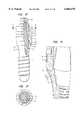
- FIG. 1Aa full screw implant with a solid conical superstructure, a slide sleeve and the impression cap in an exploded view;
- FIG. 1Bthe view according to FIG. 1A in vertical section
- FIG. 1Cthe view according to FIG. 1A with screwed-in solid conical superstructure in partial section;
- FIG. 1Dthe elements according to FIG. 1A in the assembled state, as partial section;
- FIG. 1Ethe view according to FIG. 1D in another partial section
- FIG. 1Fthe view according to FIG. 1E as section along the line A--A;
- FIG. 1Gas detail, the area with the snap element engaging around the implant shoulder, in partial section;
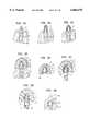
- FIG. 2Aa manipulation implant with solid conical part, a manipulation shoulder sleeve, a slide sleeve and the impression cap in an exploded view;
- FIG. 2Bthe view according to FIG. 2A in vertical partial section
- FIG. 2Cthe view according to FIG. 2B in another vertical partial section
- FIG. 2Dthe elements according to FIG. 2A in the assembled state
- FIG. 2Ethe view according to FIG. 2D in vertical partial section
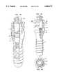
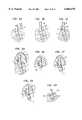
- FIG. 3Aa full screw implant with a conical superstructure (6°) with internal thread, a slide sleeve and the impression cap in an exploded view;
- FIG. 3Bthe elements according to FIG. 3A in the assembled state, in vertical partial section;
- FIG. 3Cthe view according to FIG. 3B with a conical superstructure (8°);
- FIG. 4Aa full screw implant with a polygonal superstructure, a slide sleeve and the impression cap as an exploded view in vertical partial section;
- FIG. 4Bthe elements according to FIG. 4A in the assembled state, in vertical partial section;
- FIG. 4Cthe view according to FIG. 4B in another vertical partial section
- FIG. 4Dthe view according to FIG. 4C as section along the line B--B;
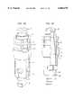
- FIG. 5Amouth situation with full screw implant sitting in the jaw bone, and solid conical superstructure fitted
- FIG. 5Bthe view according to FIG. 5A with slide sleeve pushed on;
- FIG. 5Cthe view according to FIG. 5B with impression cap pushed on;
- FIG. 5Dthe view according to FIG. 5C with impression tray applied
- FIG. 5Ethe impression obtained according to FIG. 5D;
- FIG. 5Fthe solid conical superstructure applied on the impression according to FIG. 5E;
- FIG. 5Gthe view according to FIG. 5F with manipulation shoulder sleeve attached
- FIG. 5Hthe view according to FIG. 5G with impression tray removed
- FIG. 6Athe view according to FIG. 5A with angled conical superstructure
- FIG. 6Bthe view according to FIG. 6A with impression cylinder screwed on;
- FIG. 6Cthe view according to FIG. 6B with laterally open impression cap pushed on;
- FIG. 6Dthe view according to FIG. 6C with impression tray applied
- FIG. 6Ethe impression according to FIG. 6D:
- FIG. 6Fthe view according to FIG. 6E with manipulation shoulder sleeve attached
- FIG. 6Gthe view according to FIG. 6F with filled impression cap
- FIG. 6Hthe view according to FIG. 6G as finished master cast.
- FIGS. 1A to 1Gare identical to FIGS. 1A to 1G.
- the examplefurther refers to the taking of an impression of an implant 1 fitted in the mouth of a patient, here a dental implant as a full screw.
- the implant 1has an implant head 10 widening conically upwards, and an implant shoulder 11 narrowing conically upwards.
- a superstructure parthere a solid conical superstructure 2
- the abutment 21 of the solid conical superstructure 2 projecting above the implant shoulder 11has several vertically extending grooves 22 on the outside.
- a slide sleeve 3which is divided into a sleeve section 30 open at the bottom, and a closed end-piece 31 which ends at the top.
- the cylindrical sleeve section 30is smooth on the outside, while it has an inner contour 32 complementing the abutment 21 and can be pushed onto this abutment 21.
- the impression cap 4is in principle cylindrical and open at both ends.
- the channel passage 40 running through the impression cap 4is complementary to the outer shape of the sleeve section 30, so that the impression cap 4 can be pushed in a sliding movement over the slide sleeve 3.
- the impression cap 4has a cap shoulder 41 which is complementary to the implant shoulder 11.
- the cap shoulder 41is surrounded by an elastic snap element 42 directed inwards so that it can snap over the implant shoulder 11 and releasably grip an undercut contour 13 on the implant head 10 (see FIGS. 1E and 1G).
- the impression cap 4is radially grooved, so that several retention plates 43 are obtained.
- Apertures 44may be present in the impression cap 4 for the escape of air and for the penetration or introduction of impression compound.
- the retention plates 43have the function of anchoring in the impression compound, in order to prevent the displacement or twisting of the impression cap 4.
- the slide sleeve 3 pushed onto the abutment 21reaches via the sleeve section 30 almost as far as the implant shoulder 11.
- the impression cap 4receives the sleeve section 30 in its channel passage 40, with the end-piece 31 projecting upwards from the impression cap 4.
- the inner contour 32 of the slide sleeve 3bears snugly on the outer contour of the abutment 21.
- the lower edge of the sleeve section 30acts as a clamping wedge between the abutment 21 and the impression cap 4.
- the cap shoulder 41sits practically seamlessly on the implant shoulder 11 and with resilient tensioning, the snap element 42 gripping over the implant shoulder 11 in a downward direction, towards the implant head 10, and as it were pulling the impression cap 4 onto the implant 1.
- This sequence of figuresrefers to the production of the master cast after the impression of the mouth situation has been obtained.
- the above-described slide sleeve 3 and impression cap 4, which remain embedded in the impression,are present once again.
- a manipulation implant 5, here with a solid conical abutment 51, and a manipulation shoulder sleeve 6are added in this work phase.
- the manipulation implant 5has, at the bottom, a continuation 50 and, at the top, an abutment 51 identical to the abutment 21. Above the continuation 50 with a plurality of retention plates 52, the manipulation implant 5 has a fixing plate 53 with a plate shoulder 54.
- the cylindrical, hollow manipulation shoulder sleeve 6has, at the bottom, a radially encircling, elastic locking edge 60 curved inwards. At the top, the manipulation shoulder sleeve 6 terminates via a manipulation shoulder 61 identical to the implant shoulder 11. In the manipulation shoulder sleeve 6 there are expansion slots 62 extending to the locking edge 60 for the purpose of increasing the elasticity.
- the manipulation shoulder sleeve 6is pushed so far onto the manipulation implant 5 that the locking edge 60 engages around the fixing plate 53, while the snap element 42 of the impression cap 4 engages elastically around the manipulation shoulder 61.
- the slide sleeve 3again clamps wedge-like in the impression cap 4.
- FIGS. 3A and 3Bare identical to FIGS. 3A and 3B.
- a conical superstructure 102 having an internal thread 123is shown here.
- the threaded part 120engages in the internal threaded bore 12 of the implant 1.
- the conical abutment 121 with the grooves 122 and, for example, a conicity of 6°has another outer geometry; an adapted slide sleeve 103 with an inner contour 132 complementary to the abutment 121 is accordingly provided.
- the sleeve section 130has an inner contour of 6° conicity; which then merges into an 8° conicity.
- the snap element 42again engages around the implant shoulder 11, and the lower edge of the sleeve section 130 pushes and clamps itself in the manner of a wedge between the abutment 121 and the impression cap 4.
- the end-piece 131 of the slide sleeve 103projects upwards from the impression cap 4.
- the manipulation implant to be used herewould have to have an abutment identical to the abutment 121.
- a once again modified conical superstructure 202is used; it has, for example, a conicity of 8° on the abutment 221. With the two stepped conicities of 6° and 8° in the sleeve section 130, the slide sleeve 103 can also be used here.
- a polygonal superstructure 302is now screwed with its threaded part 320 into the internal threaded bore 12 of the implant 1.
- the polygonal abutment 321here with an outer octagon, projects above the implant shoulder 11, while the horizontal abutment shoulder 324 radially surrounding the abutment 321 ends approximately flush, depending on tolerances, with the top edge of the implant shoulder 11.
- An internal threaded bore 323 in the form of a blind holeextends axially into the polygonal superstructure 302.
- a slide sleeve 303is provided with an inner contour 332 matching the abutment 321 on the sleeve section 330.
- the lower edge of the sleeve section 330sits on the abutment shoulder 324 and the end-piece 331 again projects from the impression cap 4 at the top.
- the snap element 42 of the impression cap 4engages around the implant shoulder 11.
- FIG. 5AThe mouth situation (FIG. 5A) is shown with an implant 1 sitting in the jaw bone and a solid conical superstructure 2 screwed into the implant 1.
- the slide sleeve 3is first of all pushed onto the solid conical superstructure 2 (FIG. 5B).
- the impression cap 4is pushed on (FIG. 5C).
- the sequence of pushing on the slide sleeve 3 and the impression cap 4could also take place in the reverse order.
- the impression tray 70 filled with impression compound 7is now pressed onto the implant 1 thus equipped in the direction of the jaw bone (FIG. 5D). After withdrawing the impression tray 70, the impression cap 4 and the slide sleeve 3 remain embedded in the impression compound 7, and the impression AD is obtained (FIG. 5E).
- This sequence of figuresoutlines the work steps taking the example of an angled conical superstructure 402 with an internal thread 423, where the threaded part 420 is screwed into the internal threaded bore 12 in the implant 1; this is the mouth situation (FIG. 6A).
- An impression cylinder 8is screwed into the internal thread 423 (FIG. 6B) and a laterally open impression cap 4 is pushed onto the latter and grabs the implant shoulder 11 (FIG. 6C).
- the impression ADis taken using the impression tray 70 filled with impression compound 7 (FIG. 6D), which impression is obtained after withdrawing the impression tray 70, and in which the impression cap 4 and a hollow space according to the impression cylinder 8 and the conical superstructure 402 remain behind (FIG. 6E).
- the impression cylinder 8is pushed into its hollow space and the manipulation shoulder sleeve 6 is attached (FIG. 6F) and modelling compound 71 is then filled in through the manipulation shoulder sleeve 6, so that the whole hollow space is filled up (FIG. 6G).
- Modelling compound 71is now poured onto the impression AD and, after removing the impression tray 70 in which the impression cylinder 8 remains, the finished master cast MM is obtained (FIG. 6H).
- the slide sleeve 3can be omitted entirely if the hollow space remaining in the impression cap 4, and left by the selected abutment, e.g. 21, inside the impression cap 4, is filled with impression compound.
- the impression compoundcould be introduced through the apertures 44.
- the slide sleeve 3 and the impression cap 4may be combined and designed as one piece.
- manipulation implant 5 and the manipulation shoulder sleeve 6are combined and designed as one piece.
- the manipulation shoulder sleeve 6can have, on the outer circumference, retention plates generated by radial grooving and/or radially directed apertures.
- the manipulation implant 5 and/or the manipulation shoulder sleeve 6can be omitted entirely if the hollow space remaining in the impression AD is filled with modelling material.
- the inventive conceptcan be generalized to the extent that the snap elements 42 provided on the impression cap 4 can generally have an engagement geometry engaging in the undercut contour present on the outer side of the implant end directed outwards.
- the contourcan be created by a trumpet shape of the implant end or by an incorporated undercut.
Landscapes
- Health & Medical Sciences (AREA)
- Oral & Maxillofacial Surgery (AREA)
- Dentistry (AREA)
- Epidemiology (AREA)
- Life Sciences & Earth Sciences (AREA)
- Animal Behavior & Ethology (AREA)
- General Health & Medical Sciences (AREA)
- Public Health (AREA)
- Veterinary Medicine (AREA)
- Orthopedic Medicine & Surgery (AREA)
- Dental Prosthetics (AREA)
- Prostheses (AREA)
Abstract
Description
Claims (42)
Applications Claiming Priority (3)
| Application Number | Priority Date | Filing Date | Title |
|---|---|---|---|
| CH32696 | 1996-02-08 | ||
| CH326/96 | 1996-02-08 | ||
| PCT/CH1997/000031WO1997028755A1 (en) | 1996-02-08 | 1997-01-31 | Impression system for an end of an implant projecting from a human tissue structure |
Publications (1)
| Publication Number | Publication Date |
|---|---|
| US6068478Atrue US6068478A (en) | 2000-05-30 |
Family
ID=4184473
Family Applications (1)
| Application Number | Title | Priority Date | Filing Date |
|---|---|---|---|
| US09/066,321Expired - LifetimeUS6068478A (en) | 1996-02-08 | 1997-01-31 | Impression system for an end of an implant projecting from a human tissue structure |
Country Status (16)
| Country | Link |
|---|---|
| US (1) | US6068478A (en) |
| EP (1) | EP0879024B1 (en) |
| JP (1) | JP3290995B2 (en) |
| KR (1) | KR100453761B1 (en) |
| AR (1) | AR005757A1 (en) |
| AT (1) | ATE185060T1 (en) |
| AU (1) | AU708386B2 (en) |
| BR (1) | BR9706645A (en) |
| CA (1) | CA2230615C (en) |
| DE (1) | DE59700503D1 (en) |
| DK (1) | DK0879024T3 (en) |
| ES (1) | ES2137046T3 (en) |
| ID (1) | ID15902A (en) |
| IL (1) | IL123396A0 (en) |
| TW (1) | TW332774B (en) |
| WO (1) | WO1997028755A1 (en) |
Cited By (73)
| Publication number | Priority date | Publication date | Assignee | Title |
|---|---|---|---|---|
| USD441448S1 (en) | 2000-05-08 | 2001-05-01 | Nobel Biocare Usa, Inc | Snap-in impression coping |
| US6305939B1 (en)* | 1997-07-25 | 2001-10-23 | Nobel Biocare Ab | Impression coping system for osseointegrated implants |
| FR2811883A1 (en)* | 2001-03-07 | 2002-01-25 | Gilbert Ouaknine | Tooth prosthesis screwdriver comprises to cooperate with the prosthesis and a second portion cooperating with a second element screwed within the thread |
| US6382977B1 (en) | 2000-03-02 | 2002-05-07 | Nobel Biocare Usa, Inc. | Snap-in impression coping |
| WO2002022038A3 (en)* | 2000-09-14 | 2002-06-13 | Diro Inc | Abutment for dental implant and associated components for use therewith |
| US6468081B2 (en)* | 2000-05-17 | 2002-10-22 | Jean-Claude Yeung | Dental prosthesis laboratory analog |
| US6488501B1 (en)* | 1998-06-02 | 2002-12-03 | Osteo-Ti Ltd | Transfer jig for dental implants and method for making a model |
| USD469535S1 (en) | 2001-11-01 | 2003-01-28 | Astra Tech Ab | Abutment for dental implant |
| WO2003037208A1 (en)* | 2001-11-01 | 2003-05-08 | Astra Tech Ab | Components for improved impression making |
| WO2003037207A1 (en)* | 2001-11-01 | 2003-05-08 | Astra Tech Ab | Components and method for improved impression making |
| US20030170587A1 (en)* | 2000-04-19 | 2003-09-11 | Michael Augthun | Post-shaped element for determining spatial position, especially of an implant |
| US20030211445A1 (en)* | 2002-03-13 | 2003-11-13 | Klardie Michael R. | Impression cap |
| US20040038179A1 (en)* | 2001-12-07 | 2004-02-26 | Ajay Kumar | Healing abutment |
| US20040101806A1 (en)* | 2002-09-12 | 2004-05-27 | Ajay Kumar | Dental impression coping with retention |
| US6769913B2 (en) | 2000-08-30 | 2004-08-03 | Nobel Biocare Ab | Impression cap |
| US20040180308A1 (en)* | 2003-02-05 | 2004-09-16 | Daniel Ebi | Extension piece for a dental implant, transfer aid for transferring the position of an implant and of an extension piece, and method for producing a basis for a retention element |
| US20040209227A1 (en)* | 2000-01-18 | 2004-10-21 | Porter Stephan S. | Preparation coping for creating an accurate permanent post to support a final prosthesis and method for creating the same |
| WO2004093715A1 (en)* | 2003-04-22 | 2004-11-04 | Sung-Bok Lee | Dental pin implant |
| US20040241610A1 (en)* | 2003-01-03 | 2004-12-02 | Steve Hurson | Dental implant system |
| US20050101961A1 (en)* | 2003-11-12 | 2005-05-12 | Huebner Randall J. | Bone screws |
| US20050191600A1 (en)* | 1997-04-09 | 2005-09-01 | Beaty Keith D. | Implant delivery system |
| US20060003290A1 (en)* | 2004-07-01 | 2006-01-05 | Niznick Gerald A | Endosseous one-piece screw-type dental implants |
| US20060084033A1 (en)* | 2004-10-18 | 2006-04-20 | Gittleman Neal B | Rotating winged low profile impression transfer cap |
| US7059856B2 (en)* | 2001-08-31 | 2006-06-13 | Leonard Marotta | Stable dental analog |
| AU2002250763B2 (en)* | 2001-04-27 | 2006-07-06 | Straumann Holding Ag | Assembly for handling an implant |
| US20060199150A1 (en)* | 2005-03-07 | 2006-09-07 | Niznick Gerald A | Externally-threaded, one-piece endosseous dental implant with angled abutment |
| US20060286508A1 (en)* | 2005-06-17 | 2006-12-21 | Zimmer Dental, Inc. | Dental restorative system and components |
| US7163398B2 (en)* | 2002-03-13 | 2007-01-16 | Lifecore Biomedical, Inc. | Impression cap |
| US20070037122A1 (en)* | 2005-06-17 | 2007-02-15 | Zimmer Dental, Inc. | Dental restorative system and components |
| US20070054241A1 (en)* | 2005-05-09 | 2007-03-08 | Kim Man Y | Dental implant device and correction device therefor |
| WO2007093648A1 (en) | 2006-02-16 | 2007-08-23 | Francisco Javier Garcia Saban | Dental implant assembly and device for taking a dental impression |
| US20080008981A1 (en)* | 2005-03-21 | 2008-01-10 | Friadent Gmbh | Abutment set for a dental implant |
| US7338286B2 (en) | 2002-11-13 | 2008-03-04 | Biomet 3I, Inc. | Dental implant system |
| US20080124676A1 (en)* | 2001-08-31 | 2008-05-29 | Leonard Marotta | Accurate analogs for prostheses using computer generated anatomical models |
| USD582041S1 (en)* | 2006-04-27 | 2008-12-02 | Zimmer Dental, Inc. | Impression coping |
| US20090029321A1 (en)* | 2007-07-27 | 2009-01-29 | Seiko Epson Corporation | Method for maufacturing dental implant and dental implant |
| US20090029317A1 (en)* | 2007-07-27 | 2009-01-29 | Seiko Epson Corporation | Method for manufacturing dental implant and dental implant |
| US20090029315A1 (en)* | 2007-07-27 | 2009-01-29 | Seiko Epson Corporation | Method for manufacturing dental implant and dental implant |
| US20090047630A1 (en)* | 2007-08-13 | 2009-02-19 | Biomet 3I, Inc. | Method for forming a dental prosthesis |
| US20090298015A1 (en)* | 2008-05-28 | 2009-12-03 | Global Implant Solutions, Llc | Digital Abutment For Dental Implant System |
| US20100015571A1 (en)* | 2008-07-15 | 2010-01-21 | Global Implant Solutions, Llc | Flexible Abutment For Use With A Dental Implant |
| US20100086900A1 (en)* | 2008-05-06 | 2010-04-08 | Keystone Dental, Inc. | Coping-analogue kit |
| US20100112527A1 (en)* | 2008-11-02 | 2010-05-06 | Timothy Dow Chapel | Method for fabricating an implanted dental restoration |
| US20100151420A1 (en)* | 2008-12-11 | 2010-06-17 | Ranck Roger S | Fixtures for dental implants |
| US20100151423A1 (en)* | 2008-12-11 | 2010-06-17 | Ranck Roger S | Temporary restorations and related methods |
| RU2391938C1 (en)* | 2008-12-04 | 2010-06-20 | Вадим Александрович Луганский | Method of transferring implant position from impression onto gypsum model |
| US20100159417A1 (en)* | 2008-12-18 | 2010-06-24 | Dale Whipple | Dental impression cap with engagement feature |
| US20100184002A1 (en)* | 2009-01-19 | 2010-07-22 | Ranck Roger S | Transfer copings and related methods for taking implant impressions |
| US20110086327A1 (en)* | 2009-10-09 | 2011-04-14 | Sheldon Lerner | Combination UCLA Impression Coping and Installation Procedure |
| US20110129798A1 (en)* | 2008-06-06 | 2011-06-02 | Straumann Holding Ag | Device for mounting an impression cap on a tooth implant |
| RU2425652C2 (en)* | 2009-05-22 | 2011-08-10 | Елена Владимировна Мамчиц | Method of fixation of dental prostheses on implants |
| US20110229850A1 (en)* | 2010-03-18 | 2011-09-22 | Bretton Joseph N | Dental coping and assembly with aligning anti-rotation feature |
| US20110236854A1 (en)* | 2010-03-25 | 2011-09-29 | Straumann Holding Ag | Impression cap for a dental implant |
| US20110287381A1 (en)* | 2009-02-04 | 2011-11-24 | Mid Corp. | System, method and apparatus for implementing dental implants |
| USRE43470E1 (en) | 1995-11-17 | 2012-06-12 | Nobel Biocare Services, Ag | Dental implant systems and methods |
| US20130260339A1 (en)* | 2009-11-17 | 2013-10-03 | Uab Research Foundation | High torque dental implant system |
| US8632489B1 (en) | 2011-12-22 | 2014-01-21 | A. Mateen Ahmed | Implantable medical assembly and methods |
| US8790408B2 (en) | 2001-08-31 | 2014-07-29 | Leonard Marotta | Accurate analogs for bone graft prostheses using computer generated anatomical models |
| CN103976800A (en)* | 2014-04-16 | 2014-08-13 | 玄龙培 | Impression auxiliary cap for dental implant surgery, and impression method |
| US8827702B2 (en)* | 2011-09-12 | 2014-09-09 | Cortex Dental Implant Industries, Ltd. | Driver and method |
| US8920170B2 (en) | 2011-02-21 | 2014-12-30 | Aeton Medical Llc | Abutment and abutment systems for use with implants |
| US9283057B2 (en) | 2011-02-02 | 2016-03-15 | Mid Corp. | System, apparatus and method for implementing implants |
| US20160113739A1 (en)* | 2013-06-06 | 2016-04-28 | Iulian Honig | Dental implant device, system and method of use |
| US9381112B1 (en) | 2011-10-06 | 2016-07-05 | William Eric Sponsell | Bleb drainage device, ophthalmological product and methods |
| EP2793732B1 (en) | 2011-12-21 | 2017-06-28 | bredent medical GmbH & Co. KG | Dental implant abutment and adhesive-bonding base therefor |
| US9737380B2 (en) | 2009-02-13 | 2017-08-22 | Aeton Medical Llc | Components for use with implants and related methods |
| US9861455B2 (en) | 2013-07-30 | 2018-01-09 | TI Intellectual Property Inc. | Dental implant system |
| US9925024B2 (en) | 2011-06-28 | 2018-03-27 | Biomet 3I, Llc | Dental implant and abutment tools |
| WO2018172270A1 (en) | 2017-03-20 | 2018-09-27 | Straumann Holding Ag | Implant analog |
| US10441387B2 (en) | 2012-07-09 | 2019-10-15 | Nobel Biocare Services Ag | Abutment system and dental methods |
| US11311354B2 (en) | 2018-10-09 | 2022-04-26 | Smart Denture Conversions, Llc | Screw-attached pick-up dental coping system and methods |
| US20230363865A1 (en)* | 2021-05-21 | 2023-11-16 | Hyun Seong JANG | Dental solid abutment |
| US11957538B2 (en) | 2021-12-23 | 2024-04-16 | Smart Denture Conversions, Llc | Screw-attached pick-up dental coping system, methods and accessories |
Families Citing this family (18)
| Publication number | Priority date | Publication date | Assignee | Title |
|---|---|---|---|---|
| US6203323B1 (en) | 1998-04-08 | 2001-03-20 | Implant Innovations, Inc. | Implant delivery system |
| BR9809079A (en)* | 1997-04-09 | 2002-01-15 | Implant Innovations Inc | Implant delivery system |
| EP1502558B1 (en)* | 1997-10-03 | 2008-01-23 | Biomet 3I, Inc. | Single-stage implant system |
| US6217331B1 (en) | 1997-10-03 | 2001-04-17 | Implant Innovations, Inc. | Single-stage implant system |
| US6540514B1 (en) | 1998-02-26 | 2003-04-01 | Theodore S. Falk | Method for isolating a dental implant |
| US6159010A (en)* | 1998-04-23 | 2000-12-12 | Implant Innovations, Inc. | Fenestrated dental coping |
| DE10159683A1 (en)* | 2001-11-30 | 2003-06-18 | Michael Gahlert | Dantalimplantat |
| DE102004053434B4 (en)* | 2004-11-05 | 2010-01-28 | Markus Dold | implant system |
| DE102005005402B4 (en) | 2005-02-05 | 2011-02-17 | Friadent Gmbh | Dental implant and implant system |
| US8007279B2 (en) | 2005-06-17 | 2011-08-30 | Zimmer Dental, Inc. | Dental restorative system and components |
| EA015667B1 (en)* | 2006-11-22 | 2011-10-31 | Филипп Дакремон | Supra-osseous dental implant |
| JP5473003B2 (en) | 2007-07-16 | 2014-04-16 | デンタルポイント アーゲー | Dental implant |
| ITNA20070102A1 (en)* | 2007-10-18 | 2009-04-19 | Pio Donnarumma | MEDICAL DENTAL DEVICE (STACKABLE ABUTMENT) FOR THE IMPLEMENTATION OF IMPRESSIONS AND SUCCESSFUL CONSTRUCTION OF IMPLANTS-PROSTHETIC MANUFACTURERS WITH REMOVABLE CONNECTION AND CUSTOMIZABLE FOR ANY TYPE OF PLANT. |
| WO2010075993A1 (en)* | 2009-01-02 | 2010-07-08 | Robert Laux | Casting cap having casting posts for a tooth implant |
| KR100948074B1 (en)* | 2009-03-23 | 2010-03-16 | 주식회사 이노바이오써지 | Implant prosthetic parts set and method for manufacturing replica plaster model including abutment using the parts set |
| CH704382A1 (en) | 2011-01-25 | 2012-07-31 | Dentalpoint Ag | Dentures system. |
| DE102013004175B4 (en)* | 2013-03-12 | 2017-01-26 | Bruno Spindler | Implant analog and analog bearing body |
| WO2015030289A1 (en)* | 2013-08-28 | 2015-03-05 | 라파바이오 주식회사 | Method for manufacturing dental prosthesis by using healing abutment and impression cap capable of being fastened thereto |
Citations (1)
| Publication number | Priority date | Publication date | Assignee | Title |
|---|---|---|---|---|
| DE4415670A1 (en)* | 1994-05-04 | 1995-11-09 | Degussa | Impression cap for dental implants |
- 1997
- 1997-01-31USUS09/066,321patent/US6068478A/ennot_activeExpired - Lifetime
- 1997-01-31DEDE59700503Tpatent/DE59700503D1/ennot_activeExpired - Lifetime
- 1997-01-31DKDK97900923Tpatent/DK0879024T3/enactive
- 1997-01-31CACA002230615Apatent/CA2230615C/ennot_activeExpired - Lifetime
- 1997-01-31ESES97900923Tpatent/ES2137046T3/ennot_activeExpired - Lifetime
- 1997-01-31ATAT97900923Tpatent/ATE185060T1/enactive
- 1997-01-31ILIL12339697Apatent/IL123396A0/ennot_activeIP Right Cessation
- 1997-01-31AUAU14354/97Apatent/AU708386B2/ennot_activeExpired
- 1997-01-31EPEP97900923Apatent/EP0879024B1/ennot_activeExpired - Lifetime
- 1997-01-31TWTW086101108Apatent/TW332774B/ennot_activeIP Right Cessation
- 1997-01-31BRBR9706645Apatent/BR9706645A/ennot_activeIP Right Cessation
- 1997-01-31WOPCT/CH1997/000031patent/WO1997028755A1/enactiveIP Right Grant
- 1997-01-31JPJP52801797Apatent/JP3290995B2/ennot_activeExpired - Lifetime
- 1997-01-31KRKR10-1998-0702621Apatent/KR100453761B1/ennot_activeExpired - Fee Related
- 1997-02-07IDIDP970388Apatent/ID15902A/enunknown
- 1997-02-07ARARP970100502Apatent/AR005757A1/enactiveIP Right Grant
Patent Citations (1)
| Publication number | Priority date | Publication date | Assignee | Title |
|---|---|---|---|---|
| DE4415670A1 (en)* | 1994-05-04 | 1995-11-09 | Degussa | Impression cap for dental implants |
Non-Patent Citations (4)
| Title |
|---|
| Oral Implantology, 2d rev. ed., Georg Thieme, Verlag, Stuttgart, New York, 1996, pp. 198 204.* |
| Oral Implantology, 2d rev. ed., Georg Thieme, Verlag, Stuttgart, New York, 1996, pp. 198-204. |
| Orale Implantologie, 2 ed., Georg Thieme Verlag, Stuttgart, New York, 1994, pp. 202 209.* |
| Orale Implantologie, 2 ed., Georg Thieme Verlag, Stuttgart, New York, 1994, pp. 202-209. |
Cited By (134)
| Publication number | Priority date | Publication date | Assignee | Title |
|---|---|---|---|---|
| USRE43470E1 (en) | 1995-11-17 | 2012-06-12 | Nobel Biocare Services, Ag | Dental implant systems and methods |
| US7344376B2 (en) | 1997-04-09 | 2008-03-18 | Biomet 3I, Inc. | Implant delivery system |
| US8087935B2 (en) | 1997-04-09 | 2012-01-03 | Biomet 3I, Llc | Implant delivery system |
| US20050191600A1 (en)* | 1997-04-09 | 2005-09-01 | Beaty Keith D. | Implant delivery system |
| US6305939B1 (en)* | 1997-07-25 | 2001-10-23 | Nobel Biocare Ab | Impression coping system for osseointegrated implants |
| US6488501B1 (en)* | 1998-06-02 | 2002-12-03 | Osteo-Ti Ltd | Transfer jig for dental implants and method for making a model |
| US20040209227A1 (en)* | 2000-01-18 | 2004-10-21 | Porter Stephan S. | Preparation coping for creating an accurate permanent post to support a final prosthesis and method for creating the same |
| US8002547B2 (en) | 2000-01-18 | 2011-08-23 | Biomet 3I Llc | Preparation coping for creating an accurate permanent post to support a final prosthesis and method for creating the same |
| US6382977B1 (en) | 2000-03-02 | 2002-05-07 | Nobel Biocare Usa, Inc. | Snap-in impression coping |
| US20030170587A1 (en)* | 2000-04-19 | 2003-09-11 | Michael Augthun | Post-shaped element for determining spatial position, especially of an implant |
| USD441448S1 (en) | 2000-05-08 | 2001-05-01 | Nobel Biocare Usa, Inc | Snap-in impression coping |
| US6468081B2 (en)* | 2000-05-17 | 2002-10-22 | Jean-Claude Yeung | Dental prosthesis laboratory analog |
| US6769913B2 (en) | 2000-08-30 | 2004-08-03 | Nobel Biocare Ab | Impression cap |
| US6592370B2 (en)* | 2000-09-14 | 2003-07-15 | Diro, Inc. | Abutment for dental implant and associated components for use therewith |
| US20030228555A1 (en)* | 2000-09-14 | 2003-12-11 | Morgan Vincent J. | Abutment for dental implant and associated components for use therewith |
| US7114952B2 (en)* | 2000-09-14 | 2006-10-03 | Debbie, Llc | Abutment for dental implant and associated components for use therewith |
| KR100811021B1 (en) | 2000-09-14 | 2008-03-11 | 데비, 엘엘씨 | Abutments for artificial dental implants and related components for use with them |
| WO2002022038A3 (en)* | 2000-09-14 | 2002-06-13 | Diro Inc | Abutment for dental implant and associated components for use therewith |
| FR2811883A1 (en)* | 2001-03-07 | 2002-01-25 | Gilbert Ouaknine | Tooth prosthesis screwdriver comprises to cooperate with the prosthesis and a second portion cooperating with a second element screwed within the thread |
| AU2002250763B2 (en)* | 2001-04-27 | 2006-07-06 | Straumann Holding Ag | Assembly for handling an implant |
| US20110129800A1 (en)* | 2001-08-31 | 2011-06-02 | Leonard Marotta | Accurate analogs for prosthesis using computer generated anatomical models |
| US20080124676A1 (en)* | 2001-08-31 | 2008-05-29 | Leonard Marotta | Accurate analogs for prostheses using computer generated anatomical models |
| US9855122B2 (en) | 2001-08-31 | 2018-01-02 | Leonard Marotta | Accurate analogs for prosthesis using computer generated anatomical models |
| US8790408B2 (en) | 2001-08-31 | 2014-07-29 | Leonard Marotta | Accurate analogs for bone graft prostheses using computer generated anatomical models |
| US7887327B2 (en) | 2001-08-31 | 2011-02-15 | Leonard Marotta | Accurate analogs for prostheses using computer generated anatomical models |
| US7281927B2 (en) | 2001-08-31 | 2007-10-16 | Leonard Marotta | Stable dental analog |
| US20060228674A1 (en)* | 2001-08-31 | 2006-10-12 | Leonard Marotta | Stable dental analog |
| US8425227B2 (en) | 2001-08-31 | 2013-04-23 | Leonard Marotta | Accurate analogs for prosthesis using computer generated anatomical models |
| US7059856B2 (en)* | 2001-08-31 | 2006-06-13 | Leonard Marotta | Stable dental analog |
| AU2002347710B2 (en)* | 2001-11-01 | 2007-12-06 | Astra Tech Ab | Components and method for improved impression making |
| WO2003037207A1 (en)* | 2001-11-01 | 2003-05-08 | Astra Tech Ab | Components and method for improved impression making |
| CN100415184C (en)* | 2001-11-01 | 2008-09-03 | 艾斯特勒科技公司 | Component for improved impression making |
| US6824386B2 (en) | 2001-11-01 | 2004-11-30 | Astra Tech Ab | Components for improved impression making |
| KR100928654B1 (en)* | 2001-11-01 | 2009-11-27 | 아스트라 테크 에이비 | Improved impression making components and manufacturing method thereof |
| US20040234926A1 (en)* | 2001-11-01 | 2004-11-25 | Astra Tech Ab | Components for improved impression making |
| USD469535S1 (en) | 2001-11-01 | 2003-01-28 | Astra Tech Ab | Abutment for dental implant |
| RU2290127C2 (en)* | 2001-11-01 | 2006-12-27 | Астра Тек АБ | Components and method of improved production of imprint |
| CN100372508C (en)* | 2001-11-01 | 2008-03-05 | 艾斯特勒科技公司 | Components for improved impression taking |
| WO2003037208A1 (en)* | 2001-11-01 | 2003-05-08 | Astra Tech Ab | Components for improved impression making |
| US6951460B2 (en) | 2001-11-01 | 2005-10-04 | Astra Tech Ab | Components and method for improved impression making |
| US20040038179A1 (en)* | 2001-12-07 | 2004-02-26 | Ajay Kumar | Healing abutment |
| US7204692B2 (en)* | 2002-03-13 | 2007-04-17 | Lifecore Biomedical, Inc. | Impression cap |
| US20030211445A1 (en)* | 2002-03-13 | 2003-11-13 | Klardie Michael R. | Impression cap |
| US7163398B2 (en)* | 2002-03-13 | 2007-01-16 | Lifecore Biomedical, Inc. | Impression cap |
| US7066736B2 (en) | 2002-09-12 | 2006-06-27 | Zimmer Dental, Inc. | Dental impression coping with retention |
| US20040101806A1 (en)* | 2002-09-12 | 2004-05-27 | Ajay Kumar | Dental impression coping with retention |
| US7484959B2 (en) | 2002-11-13 | 2009-02-03 | Biomet 3I, Llc | Dental implant system |
| US7338286B2 (en) | 2002-11-13 | 2008-03-04 | Biomet 3I, Inc. | Dental implant system |
| US9549793B2 (en) | 2002-11-13 | 2017-01-24 | Biomet 3I, Llc | Dental implant system |
| US20080102420A1 (en)* | 2002-11-13 | 2008-05-01 | Porter Stephan S | Dental implant system |
| US9931182B2 (en) | 2002-11-13 | 2018-04-03 | Biomet 3I, Llc | Dental implant system |
| US8636511B2 (en) | 2002-11-13 | 2014-01-28 | Biomet 3I, Llc | Dental implant system |
| US9883927B2 (en) | 2002-11-13 | 2018-02-06 | Biomet 3I, Llc | Dental implant system |
| US20040241610A1 (en)* | 2003-01-03 | 2004-12-02 | Steve Hurson | Dental implant system |
| US20060204928A1 (en)* | 2003-01-03 | 2006-09-14 | Steve Hurson | Dental implant system |
| US20040180308A1 (en)* | 2003-02-05 | 2004-09-16 | Daniel Ebi | Extension piece for a dental implant, transfer aid for transferring the position of an implant and of an extension piece, and method for producing a basis for a retention element |
| US7654824B2 (en)* | 2003-02-05 | 2010-02-02 | Straumann Holding Ag | Extension piece for a dental implant, transfer aid for transferring the position of an implant and of an extension piece, and method for producing a basis for a retention element |
| WO2004093715A1 (en)* | 2003-04-22 | 2004-11-04 | Sung-Bok Lee | Dental pin implant |
| US20050101961A1 (en)* | 2003-11-12 | 2005-05-12 | Huebner Randall J. | Bone screws |
| US20060003290A1 (en)* | 2004-07-01 | 2006-01-05 | Niznick Gerald A | Endosseous one-piece screw-type dental implants |
| US20060084033A1 (en)* | 2004-10-18 | 2006-04-20 | Gittleman Neal B | Rotating winged low profile impression transfer cap |
| US7632096B2 (en)* | 2004-10-18 | 2009-12-15 | Gittleman Neal B | Rotating winged low profile impression transfer cap |
| US20060199150A1 (en)* | 2005-03-07 | 2006-09-07 | Niznick Gerald A | Externally-threaded, one-piece endosseous dental implant with angled abutment |
| US20080008981A1 (en)* | 2005-03-21 | 2008-01-10 | Friadent Gmbh | Abutment set for a dental implant |
| US7393210B2 (en)* | 2005-05-09 | 2008-07-01 | Man Yong Kim | Dental implant device and correction device therefor |
| US20070054241A1 (en)* | 2005-05-09 | 2007-03-08 | Kim Man Y | Dental implant device and correction device therefor |
| US9125710B2 (en) | 2005-06-17 | 2015-09-08 | Zimmer Dental, Inc. | Dental restorative system and components |
| US20060286508A1 (en)* | 2005-06-17 | 2006-12-21 | Zimmer Dental, Inc. | Dental restorative system and components |
| US20070037122A1 (en)* | 2005-06-17 | 2007-02-15 | Zimmer Dental, Inc. | Dental restorative system and components |
| US8430668B2 (en) | 2005-06-17 | 2013-04-30 | Zimmer Dental, Inc. | Dental restorative system and components |
| US8506296B2 (en) | 2005-06-17 | 2013-08-13 | Zimmer Dental, Inc. | Dental restorative system and components |
| US20090035721A1 (en)* | 2006-02-16 | 2009-02-05 | Francisco Javier Garcia Saban | Dental implant and dental impression-taking device assembly |
| WO2007093648A1 (en) | 2006-02-16 | 2007-08-23 | Francisco Javier Garcia Saban | Dental implant assembly and device for taking a dental impression |
| USD582041S1 (en)* | 2006-04-27 | 2008-12-02 | Zimmer Dental, Inc. | Impression coping |
| US20090029315A1 (en)* | 2007-07-27 | 2009-01-29 | Seiko Epson Corporation | Method for manufacturing dental implant and dental implant |
| US20090029321A1 (en)* | 2007-07-27 | 2009-01-29 | Seiko Epson Corporation | Method for maufacturing dental implant and dental implant |
| US8683692B2 (en) | 2007-07-27 | 2014-04-01 | Seiko Epson Corporation | Method for manufacturing dental implant and dental implant |
| US20090029317A1 (en)* | 2007-07-27 | 2009-01-29 | Seiko Epson Corporation | Method for manufacturing dental implant and dental implant |
| US8398401B2 (en)* | 2007-07-27 | 2013-03-19 | Seiko Epson Corporation | Method for manufacturing dental implant and dental implant |
| US8782897B2 (en) | 2007-07-27 | 2014-07-22 | Seiko Epson Corporation | Method for manufacturing dental implant |
| US8408905B2 (en)* | 2007-07-27 | 2013-04-02 | Seiko Epson Corporation | Method for manufacturing dental implant and dental implant |
| US8398402B2 (en)* | 2007-07-27 | 2013-03-19 | Seiko Epson Corporation | Method for maufacturing dental implant and dental implant |
| US8961178B2 (en) | 2007-07-27 | 2015-02-24 | Seiko Epson Corporation | Method for manufacturing dental implant and dental implant |
| US7632095B2 (en) | 2007-08-13 | 2009-12-15 | Biomet 3I, Inc. | Method for forming a dental prosthesis |
| US20090047630A1 (en)* | 2007-08-13 | 2009-02-19 | Biomet 3I, Inc. | Method for forming a dental prosthesis |
| US20100086900A1 (en)* | 2008-05-06 | 2010-04-08 | Keystone Dental, Inc. | Coping-analogue kit |
| US20090298015A1 (en)* | 2008-05-28 | 2009-12-03 | Global Implant Solutions, Llc | Digital Abutment For Dental Implant System |
| US9326832B2 (en) | 2008-06-06 | 2016-05-03 | Straumann Holding Ag | Device for mounting an impression cap on a tooth implant |
| US20110129798A1 (en)* | 2008-06-06 | 2011-06-02 | Straumann Holding Ag | Device for mounting an impression cap on a tooth implant |
| US20100015571A1 (en)* | 2008-07-15 | 2010-01-21 | Global Implant Solutions, Llc | Flexible Abutment For Use With A Dental Implant |
| US20100112527A1 (en)* | 2008-11-02 | 2010-05-06 | Timothy Dow Chapel | Method for fabricating an implanted dental restoration |
| RU2391938C1 (en)* | 2008-12-04 | 2010-06-20 | Вадим Александрович Луганский | Method of transferring implant position from impression onto gypsum model |
| US20100151420A1 (en)* | 2008-12-11 | 2010-06-17 | Ranck Roger S | Fixtures for dental implants |
| US20100151423A1 (en)* | 2008-12-11 | 2010-06-17 | Ranck Roger S | Temporary restorations and related methods |
| US20100159417A1 (en)* | 2008-12-18 | 2010-06-24 | Dale Whipple | Dental impression cap with engagement feature |
| US8075313B2 (en) | 2009-01-19 | 2011-12-13 | Aeton Medical Llc | Transfer copings and related methods for taking implant impressions |
| US20100184002A1 (en)* | 2009-01-19 | 2010-07-22 | Ranck Roger S | Transfer copings and related methods for taking implant impressions |
| US8936468B2 (en) | 2009-01-19 | 2015-01-20 | Roger S. Ranck | Transfer copings and related methods for taking implant impressions |
| US8827704B2 (en)* | 2009-02-04 | 2014-09-09 | Mid Corp | System, method and apparatus for implementing dental implants |
| US20110287381A1 (en)* | 2009-02-04 | 2011-11-24 | Mid Corp. | System, method and apparatus for implementing dental implants |
| US9737380B2 (en) | 2009-02-13 | 2017-08-22 | Aeton Medical Llc | Components for use with implants and related methods |
| RU2425652C2 (en)* | 2009-05-22 | 2011-08-10 | Елена Владимировна Мамчиц | Method of fixation of dental prostheses on implants |
| US20110086327A1 (en)* | 2009-10-09 | 2011-04-14 | Sheldon Lerner | Combination UCLA Impression Coping and Installation Procedure |
| US20130260339A1 (en)* | 2009-11-17 | 2013-10-03 | Uab Research Foundation | High torque dental implant system |
| US20110229850A1 (en)* | 2010-03-18 | 2011-09-22 | Bretton Joseph N | Dental coping and assembly with aligning anti-rotation feature |
| US20110236854A1 (en)* | 2010-03-25 | 2011-09-29 | Straumann Holding Ag | Impression cap for a dental implant |
| US8851890B2 (en)* | 2010-03-25 | 2014-10-07 | Straumann Holding Ag | Impression cap for a dental implant |
| US9283057B2 (en) | 2011-02-02 | 2016-03-15 | Mid Corp. | System, apparatus and method for implementing implants |
| US8920170B2 (en) | 2011-02-21 | 2014-12-30 | Aeton Medical Llc | Abutment and abutment systems for use with implants |
| US10952826B2 (en) | 2011-06-28 | 2021-03-23 | Biomet 3I, Llc | System and method of dental implant and interface to abutment for restoration |
| US10201405B2 (en) | 2011-06-28 | 2019-02-12 | Biomet 3I, Llc | System and method of dental implant and interface to abutment for restoration |
| US9925024B2 (en) | 2011-06-28 | 2018-03-27 | Biomet 3I, Llc | Dental implant and abutment tools |
| US8827702B2 (en)* | 2011-09-12 | 2014-09-09 | Cortex Dental Implant Industries, Ltd. | Driver and method |
| US11065154B1 (en) | 2011-10-06 | 2021-07-20 | William Eric Sponsel | Bleb drainage device, ophthalmic product and methods |
| US9381112B1 (en) | 2011-10-06 | 2016-07-05 | William Eric Sponsell | Bleb drainage device, ophthalmological product and methods |
| EP2793732B1 (en) | 2011-12-21 | 2017-06-28 | bredent medical GmbH & Co. KG | Dental implant abutment and adhesive-bonding base therefor |
| US8632489B1 (en) | 2011-12-22 | 2014-01-21 | A. Mateen Ahmed | Implantable medical assembly and methods |
| US10441387B2 (en) | 2012-07-09 | 2019-10-15 | Nobel Biocare Services Ag | Abutment system and dental methods |
| US12390309B2 (en) | 2012-07-09 | 2025-08-19 | Nobel Biocare Services Ag | Abutment system and dental methods |
| US11116609B2 (en)* | 2013-06-06 | 2021-09-14 | Abracadabra Implants Ltd | Dental implant device, system and method of use |
| US20160113739A1 (en)* | 2013-06-06 | 2016-04-28 | Iulian Honig | Dental implant device, system and method of use |
| US9861455B2 (en) | 2013-07-30 | 2018-01-09 | TI Intellectual Property Inc. | Dental implant system |
| CN103976800A (en)* | 2014-04-16 | 2014-08-13 | 玄龙培 | Impression auxiliary cap for dental implant surgery, and impression method |
| CN103976800B (en)* | 2014-04-16 | 2016-05-04 | 玄龙培 | Die Auxiliary cap and method for marking for tooth-implanting operation |
| US11331171B2 (en) | 2017-03-20 | 2022-05-17 | Straumann Holding Ag | Implant analog |
| WO2018172270A1 (en) | 2017-03-20 | 2018-09-27 | Straumann Holding Ag | Implant analog |
| EP3868329A1 (en) | 2017-03-20 | 2021-08-25 | Straumann Holding AG | Implant analog |
| US11311354B2 (en) | 2018-10-09 | 2022-04-26 | Smart Denture Conversions, Llc | Screw-attached pick-up dental coping system and methods |
| US11937992B1 (en) | 2018-10-09 | 2024-03-26 | Smart Denture Conversions, Llc | Screw-attached pick-up dental coping system and methods |
| US12156781B1 (en) | 2018-10-09 | 2024-12-03 | Smart Denture Conversions, Llc | Screw-attached pick-up dental coping system and methods |
| US12318266B1 (en) | 2018-10-09 | 2025-06-03 | Smart Denture Conversions, Llc | Screw-attached pick-up dental coping systems and methods |
| US12318265B2 (en) | 2018-10-09 | 2025-06-03 | Smart Denture Conversions, Llc | Screw-attached pick-up dental coping system and methods |
| US20230363865A1 (en)* | 2021-05-21 | 2023-11-16 | Hyun Seong JANG | Dental solid abutment |
| US11957538B2 (en) | 2021-12-23 | 2024-04-16 | Smart Denture Conversions, Llc | Screw-attached pick-up dental coping system, methods and accessories |
Also Published As
| Publication number | Publication date |
|---|---|
| EP0879024A1 (en) | 1998-11-25 |
| KR100453761B1 (en) | 2004-12-17 |
| AU1435497A (en) | 1997-08-28 |
| CA2230615A1 (en) | 1997-08-14 |
| DE59700503D1 (en) | 1999-11-04 |
| CA2230615C (en) | 2000-05-30 |
| AR005757A1 (en) | 1999-07-14 |
| ATE185060T1 (en) | 1999-10-15 |
| IL123396A0 (en) | 1998-09-24 |
| BR9706645A (en) | 1999-01-12 |
| JP3290995B2 (en) | 2002-06-10 |
| KR19990064140A (en) | 1999-07-26 |
| ES2137046T3 (en) | 1999-12-01 |
| WO1997028755A1 (en) | 1997-08-14 |
| AU708386B2 (en) | 1999-08-05 |
| DK0879024T3 (en) | 2000-03-27 |
| ID15902A (en) | 1997-08-14 |
| EP0879024B1 (en) | 1999-09-29 |
| JPH11503655A (en) | 1999-03-30 |
| TW332774B (en) | 1998-06-01 |
Similar Documents
| Publication | Publication Date | Title |
|---|---|---|
| US6068478A (en) | Impression system for an end of an implant projecting from a human tissue structure | |
| JP3414757B2 (en) | Apparatus for forming dentures | |
| US7014464B2 (en) | Multi-part abutment and transfer cap for use with an endosseous dental implant with non-circular, beveled implant/abutment interface | |
| US5688123A (en) | Transfer cap for dental implants | |
| US6358050B1 (en) | Dental implant systems | |
| US5368483A (en) | Device-for fixing a dental prosthesis to a jaw bone | |
| EP0695147B1 (en) | Spacing member for tooth implant | |
| EP0814724B1 (en) | Device for connecting a dental implant to a conical secondary element | |
| US5904483A (en) | Dental implant systems and methods | |
| EP0195006B1 (en) | Implant for attachment of dental prostheses | |
| US6464500B1 (en) | Dental implant and abutment system | |
| US20060008763A1 (en) | Device and arrangement for fixture installation | |
| US20050019726A1 (en) | Implant | |
| EP0727193A1 (en) | Universal precision dental transfer for endosseous implants | |
| AU2002347711A1 (en) | Components for improved impression making | |
| EP1448113A1 (en) | Components for improved impression making | |
| JP2010519995A (en) | Dental implant, abutment structure and method for implanting dental implant | |
| US5549475A (en) | Enossal single-tooth implant | |
| JP2010172703A (en) | Impression post for dental implant | |
| KR19990064141A (en) | Impression system for implants with impression cap | |
| US20060127849A1 (en) | Dental implant system | |
| US20080032262A1 (en) | Dental implant system and method thereof | |
| US20210068930A1 (en) | Impression Post for a Dental Implant | |
| WO2005089669A1 (en) | Dental implant |
Legal Events
| Date | Code | Title | Description |
|---|---|---|---|
| AS | Assignment | Owner name:INSTITUT STRAUMANN AG, SWITZERLAND Free format text:ASSIGNMENT OF ASSIGNORS INTEREST;ASSIGNORS:GRANDE, VINCENZO;BAUMGARTNER, RETO;TSCHIRKY, ROGER;REEL/FRAME:009717/0140;SIGNING DATES FROM 19971218 TO 19971222 | |
| STCF | Information on status: patent grant | Free format text:PATENTED CASE | |
| FEPP | Fee payment procedure | Free format text:PAT HOLDER NO LONGER CLAIMS SMALL ENTITY STATUS, ENTITY STATUS SET TO UNDISCOUNTED (ORIGINAL EVENT CODE: STOL); ENTITY STATUS OF PATENT OWNER: LARGE ENTITY | |
| FEPP | Fee payment procedure | Free format text:PAYOR NUMBER ASSIGNED (ORIGINAL EVENT CODE: ASPN); ENTITY STATUS OF PATENT OWNER: LARGE ENTITY | |
| FPAY | Fee payment | Year of fee payment:4 | |
| FPAY | Fee payment | Year of fee payment:8 | |
| AS | Assignment | Owner name:STRAUMANN HOLDING AG, SWITZERLAND Free format text:ASSIGNMENT OF ASSIGNORS INTEREST;ASSIGNOR:INSTITUT STRAUMANN AG;REEL/FRAME:023586/0351 Effective date:20070108 | |
| FEPP | Fee payment procedure | Free format text:PAYER NUMBER DE-ASSIGNED (ORIGINAL EVENT CODE: RMPN); ENTITY STATUS OF PATENT OWNER: LARGE ENTITY Free format text:PAYOR NUMBER ASSIGNED (ORIGINAL EVENT CODE: ASPN); ENTITY STATUS OF PATENT OWNER: LARGE ENTITY | |
| FPAY | Fee payment | Year of fee payment:12 |