US6067481A - Virtual magnetic tape drive library system - Google Patents
Virtual magnetic tape drive library systemDownload PDFInfo
- Publication number
- US6067481A US6067481AUS08/968,145US96814597AUS6067481AUS 6067481 AUS6067481 AUS 6067481AUS 96814597 AUS96814597 AUS 96814597AUS 6067481 AUS6067481 AUS 6067481A
- Authority
- US
- United States
- Prior art keywords
- tape
- logical sub
- virtual
- tape cartridge
- logical
- Prior art date
- Legal status (The legal status is an assumption and is not a legal conclusion. Google has not performed a legal analysis and makes no representation as to the accuracy of the status listed.)
- Expired - Lifetime
Links
Images


Classifications
- G—PHYSICS
- G06—COMPUTING OR CALCULATING; COUNTING
- G06F—ELECTRIC DIGITAL DATA PROCESSING
- G06F3/00—Input arrangements for transferring data to be processed into a form capable of being handled by the computer; Output arrangements for transferring data from processing unit to output unit, e.g. interface arrangements
- G06F3/06—Digital input from, or digital output to, record carriers, e.g. RAID, emulated record carriers or networked record carriers
- G06F3/0601—Interfaces specially adapted for storage systems
- G06F3/0668—Interfaces specially adapted for storage systems adopting a particular infrastructure
- G06F3/0671—In-line storage system
- G06F3/0673—Single storage device
- G06F3/0682—Tape device
- G—PHYSICS
- G06—COMPUTING OR CALCULATING; COUNTING
- G06F—ELECTRIC DIGITAL DATA PROCESSING
- G06F3/00—Input arrangements for transferring data to be processed into a form capable of being handled by the computer; Output arrangements for transferring data from processing unit to output unit, e.g. interface arrangements
- G06F3/06—Digital input from, or digital output to, record carriers, e.g. RAID, emulated record carriers or networked record carriers
- G06F3/0601—Interfaces specially adapted for storage systems
- G06F3/0602—Interfaces specially adapted for storage systems specifically adapted to achieve a particular effect
- G06F3/0608—Saving storage space on storage systems
- G—PHYSICS
- G06—COMPUTING OR CALCULATING; COUNTING
- G06F—ELECTRIC DIGITAL DATA PROCESSING
- G06F3/00—Input arrangements for transferring data to be processed into a form capable of being handled by the computer; Output arrangements for transferring data from processing unit to output unit, e.g. interface arrangements
- G06F3/06—Digital input from, or digital output to, record carriers, e.g. RAID, emulated record carriers or networked record carriers
- G06F3/0601—Interfaces specially adapted for storage systems
- G06F3/0602—Interfaces specially adapted for storage systems specifically adapted to achieve a particular effect
- G06F3/061—Improving I/O performance
- G—PHYSICS
- G06—COMPUTING OR CALCULATING; COUNTING
- G06F—ELECTRIC DIGITAL DATA PROCESSING
- G06F3/00—Input arrangements for transferring data to be processed into a form capable of being handled by the computer; Output arrangements for transferring data from processing unit to output unit, e.g. interface arrangements
- G06F3/06—Digital input from, or digital output to, record carriers, e.g. RAID, emulated record carriers or networked record carriers
- G06F3/0601—Interfaces specially adapted for storage systems
- G06F3/0628—Interfaces specially adapted for storage systems making use of a particular technique
- G06F3/0662—Virtualisation aspects
- G06F3/0664—Virtualisation aspects at device level, e.g. emulation of a storage device or system
- G—PHYSICS
- G11—INFORMATION STORAGE
- G11B—INFORMATION STORAGE BASED ON RELATIVE MOVEMENT BETWEEN RECORD CARRIER AND TRANSDUCER
- G11B20/00—Signal processing not specific to the method of recording or reproducing; Circuits therefor
- G—PHYSICS
- G11—INFORMATION STORAGE
- G11B—INFORMATION STORAGE BASED ON RELATIVE MOVEMENT BETWEEN RECORD CARRIER AND TRANSDUCER
- G11B20/00—Signal processing not specific to the method of recording or reproducing; Circuits therefor
- G11B20/10—Digital recording or reproducing
- G11B20/12—Formatting, e.g. arrangement of data block or words on the record carriers
- G11B20/1201—Formatting, e.g. arrangement of data block or words on the record carriers on tapes
- G11B20/1202—Formatting, e.g. arrangement of data block or words on the record carriers on tapes with longitudinal tracks only
Definitions
- the inventionrelates generally to virtual magnetic tape library system and more precisely to a virtual multi-tape cartridge unit for use within a tape drive subsystem that cooperates with a host computer controller to form the virtual magnetic tape library system.
- a conventional magnetic tape drive library systemincludes a number of tape drive slots; a number of magnetic tape cartridge magazine slots; and a tape cartridge elevator positioned intermediate the tape drive slots and the magnetic tape cartridge magazine slots.
- the elevatoris linearly movable along a guide shaft and may be actuated by a motor for positioning the elevator adjacent to either a magazine slot or a tape drive slot.
- the elevatorincludes a mechanism for engaging a tape cartridge; extracting the tape cartridge from the magazine slot and for inserting the tape cartridge into a targeted tape drive. After completion of data processing operations with a particular tape cartridge, the elevator mechanism will again engage the tape cartridge and transport the cartridge back to its original magazine slot.
- the tape drive library systemfurther includes a housing having one side wall adapted for receiving the number of tape cartridge magazines, and another side wall adapted for receiving the number of tape drives.
- the tape cartridge magazinesare typically loaded with a plurality of tape cartridges prior to being introduced to the library system.
- An external host computer controlleris connected to the tape library system for controlling data processing operations during use of the system.
- the host computer controllerissues commands to a microcontroller that is preprogrammed with a media changer command control set.
- the command setessentially controls functional operations of the tape library system, such as: selecting and loading a tape cartridge, as well as formatting, locating, overwriting, erasing, and reading/writing data on the magnetic storage tape within the tape cartridge.
- One drawback of conventional mechanized tape library systemsis the relatively long response time to a request for data.
- the long response timeis principally attributed to the inherent mechanical latencies defined within the system.
- the mechanical latencies involved in a request for dataare derived from the steps the library system must follow in order to fulfill the data request, such as, moving an elevator to a tape cartridge magazine slot and physically extracting the cartridge. Thereafter the elevator must move the cartridge to a targeted tape drive and after loading the cartridge into the tape drive, the drive must spool the tape to the appropriate storage location of the sought after data stored on the tape. Because of such data transfer latencies, tape library system applications have been limited to archival storage/retrieval applications for a relatively large number of faster input/output data processing systems such as disk drives or solid state electronic storage devices.
- tape library systemsAnother drawback of tape library systems is directed to the under utilization of the storage capacity of the tape cartridges within the tape library system. More precisely, since conventional tape cartridges require sequential data access, a conventional tape library system inherently requires substantial system resources to store/retrieve many different types of user data on a single tape cartridge or to split user data between the tail end of one cartridge and the beginning of another cartridge. Therefore, tape library systems may store a single type of user data on a single tape cartridge and simply begin storage of another type of user data on a subsequent tape cartridge regardless of whether the former tape cartridge is full. This significantly under utilizes the storage capacity of a tape library system.
- a hitherto unsolved needhas remained for a simplified magnetic tape drive library system with increased data access rates that may make substantial use of current control microcode, e.g., media changer command control sets. Further, a need has remained for a simplified magnetic tape drive library system that fully uses the storage capacity of a tape cartridge.
- a virtual multi-tape cartridge unitfor use within a magnetic tape drive subsystem.
- the virtual multi-tape cartridge unitincludes a housing that has a hollow central cavity with a rotatably mounted central spool.
- the central spoolhas magnetic tape wound thereon for supplying the magnetic tape drive subsystem with magnetic tape during data processing operations.
- the magnetic tapehas a number of parallel longitudinal data tracks defined thereon, wherein the data tracks are arranged into a number of track groups.
- Each track grouphas a logical beginning of media (BOM) field and a logical end of media (EOM) field positioned near respective ends thereof.
- BOMlogical beginning of media
- EOMlogical end of media
- the virtual multi-tape cartridge unitmay be used within a single tape drive in conjunction with a host computer controller system to form a virtual magnetic tape drive library system.
- the hostessentially communicates data processing control information to a virtual library microcontroller within the tape drive subsystem.
- the media changer control commandswhich are implemented in the form of microcode programmed into the host, require minimal or no modifications from the media changer control commands used in a conventional mechanized tape loader library systems. Therefore, minimal or no programming is required in retrofitting the mechanized tape loader library system with the instant invention.
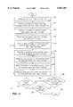
- FIG. 1is a block diagram of the virtual tape library system connected to a host computer controller.
- FIG. 2is structural/electrical block diagram illustrating structural mechanical and electrical features of the FIG. 1 example of the present invention.
- FIG. 3is a series of diagrams of magnetic tapes having data tracks that are subdivided into a number of individually identified track groups that further define sub-tape cartridges.
- FIG. 4shows a flow chart illustrating one preferred method for carrying out data processing operations with the virtual tape library system, shown in FIGS. 1-3, in accordance with principles of the present invention.
- a virtual magnetic tape drive library system 5that includes a host computer controller 10, a tape drive subsystem 15 and a virtual multi-tape cartridge unit 20.
- the host computer controller 10is connected by means of a data communication bus 7 to the tape drive subsystem 15 and issues data processing control commands to the tape drive subsystem 15.
- One preferred data communication bus for forming such a connectionis a Small Computer System Interconnect bus, e.g. a SCSI-2 bus.
- one preferred control command setis known as the SCSI-2 medium changer command set.
- This medium changer command setis programmed into the virtual library microcontroller 12 in the form of microcode and thus predefines functions available to the virtual tape library system 5.
- Typical data processing control commandsinclude, selecting and loading a virtual multi-tape cartridge unit 20, as well as formatting, locating, overwriting, erasing, and reading/writing data on the magnetic storage tape 25 within the virtual multi-tape cartridge unit 20.
- this control command setwhich is programmed in to the host 10 computer controller, can control the data processing functions of a single tape drive subsystem 15 incorporating the single multi-tape cartridge unit 20 with minimal or no modification to the command control set.
- a tape drive subsystem 15generally comprises a rectangular housing 30 that has a base (not shown) for supporting two spindle motors.
- the first spindle motor 35has a permanently mounted take-up spool 40 dimensioned to accept a relatively high speed streaming magnetic tape 25.
- the second spindle motor 45is adapted to accept the removable virtual multi-tape cartridge unit 20.
- the removable virtual multi-tape cartridge unit 20is manually or automatically inserted into the drive 15 via a slot (not shown) formed on the drive's housing 30. Upon insertion of the virtual multi-tape cartridge unit 20 into the slot, the cartridge 20 engages the second spindle motor 45.
- the magnetic tape 25 within the removable cartridge 20is connected to the permanently mounted take-up spool 40 by means of a mechanical buckling mechanism (not shown).
- a number of rollers R1-R6 positioned intermediate the multi-tape cartridge unit 20 and the permanent take-up spool 40guide the magnetic tape 25 as it traverses at relatively high speeds back and forth between the multi-tape cartridge unit 20 and the permanently mounted take-up spool 40.
- a magnetic tape head 50 positioned along the tape path 55may read/write a multiplicity of parallel longitudinal data tracks 60 on the tape as the tape streams back and forth between the take-up spool 40 and the multi-tape cartridge unit 20.
- the virtual multi-tape cartridge unit 20 for use within the magnetic tape drive subsystem 15includes a housing 30 that has a hollow central cavity 65.
- a central supply spool 70 with the magnetic tape 25 wound thereonis rotatably mounted within the cavity 65 and supplies magnetic tape 25 to the tape drive subsystem 15.
- the parallel longitudinal data tracks 60 defined on the magnetic tape 25are arranged into a number of track groups 75.
- each track group 75is individually associated with an identifying logical beginning of media (BOM) field 80 and a logical end of media (EOM) field 85 positioned near respective ends thereof.
- BOMidentifying logical beginning of media
- EOMlogical end of media
- a single multi-tape cartridge unit 20may include a multiplicity of longitudinal data tracks 60 that are subdivided into a predetermined number of logical sub-tape cartridges 90 with each logical sub-tape cartridge 90 having a unique identifier field, e.g. logical BOM 80 and EOM 85 fields respectively.
- the logical BOM 80 and EOM 85 fieldsmay each comprise a unique series of binary symbols, e.g. 1's and 0's, for identifying the position of each logical sub-tape cartridge 90. More preferably, the logical BOM 80 and EOM 85 fields may each be registered to either a physical beginning of tape (BOT) 101 hole or a physical end of tape (EOT) 102 hole. More precisely, the logical BOM 80 fields may be registered to the BOT 101 hole and the logical EOM 85 fields may be defined by a predetermined tachometer count distance measured from the BOT 101 hole. Alternatively, the logical BOM 80 fields may be registered to the EOT hole and the logical EOM 85 fields may be defined by a predetermined tachometer count distance measured from the EOT 102 hole.
- one of the tape guide rollers R6is coupled to an optical tachometer encoder disk 54 which generates signal patterns in relation to actual tape distance traveled in the forward and in the reverse tape 25 directions.
- a tachometer module 56generates a collimated light beam which passes through the encoder disk to a photodetector array which puts out electrical signals indicative of this tape movement.
- a tachometer circuit 58monitors the electrical signals, determines relative tape distance traveled, and communicates such information to the virtual library microcontroller 12.
- one preferred data track grouping 75comprises each sub-tape cartridge 90 having at least one longitudinal data track 60 traversing the length of the tape 25 as shown in FIG. 3A.
- Another preferred data track grouping 75includes a number of pairs of parallel longitudinal data tracks 60, where one or more data tracks 60 are processed in a forward tape 25 direction and one or more data tracks 60 are processed in a reverse tape 25 direction as shown in FIG. 3B.
- the longitudinal data tracks 60 grouped into each sub-tape cartridge 90 defined on the magnetic tape 25may be further subdivided into a number of partitions 95.
- the partitions 95may also each have unique identifier fields 100 positioned near the respective ends of the partitions 95.
- the identifier fieldsmay include a unique series of 1's and 0's for individually identify each partition 95.
- a read/write headmay be moved directly between partitions defined within the same logical sub-tape cartridge or alternatively, the read/write head may be moved directly between partitions defined within different logical sub-tape cartridges.
- yet another preferred data track grouping 75includes a number of logical sub-tape cartridges 90 defined along the longitudinal length of the tape 25.
- the data tracks 60 defined within the sub-tape cartridges 90extend a distance less than the entire length of the tape 25. More precisely, the data tracks 60 of each sub-tape cartridge 90 are confined to a predetermined segment of the tape 25, wherein each segment defines a logical sub-tape cartridge.
- each logical sub-tape cartridge 90may include any one of the data track 60 formats previously described in FIGS. 3A-3C.
- the physical BOT 101 and EOT 102 holes positioned intermediate the sub-tape cartridges 90operate as either a BOT 101 or an EOT 102 hole.
- the BOT 101 holeis defined at a proximate end of the sub-tape cartridge 90 and the EOT 102 hole is defined at the distal end of the sub-tape cartridge 90.
- a former EOT 102 holemay operate as a BOT 101 hole.
- a single tape drive subsystem 15emulates a conventional multiple tape cartridge tape library system (not shown) by employing a single virtual multi-tape cartridge unit 20.
- the method of implementing the virtual magnetic tape library system 5includes the steps of loading the virtual multi-tape cartridge unit into the magnetic tape drive subsystem 15 and then initializing the multi-tape cartridge unit 200 with a format circuit 52, as shown in FIG. 2.
- the format circuit 52essentially formats and defines a plurality of logical sub-tape cartridges within the multi-tape cartridge unit 210.
- the format circuitfurther defines a plurality of partitions within each of the logical sub-tape cartridges 220.
- each of the logical sub-tape cartridgesare registered with the physical BOT and EOT holes 230 such that the distances between the holes and the logical sub-tape cartridges can be sensed and measured. Thus, this measured distance is used for controlling and moving a read/write head to a selected partition location defined within the logical sub-tape cartridge 250. Accordingly, the computer controller 10 issues a command to the tape drive subsystem 15 for selecting a tape cartridge and translating the desired tape cartridge into a logical sub-tape cartridge 240. Then the computer controller 10 may select a desired partition location defined within the logical sub-tape cartridge 242.
- the virtual library microcontroller 12After selecting the partition location, the virtual library microcontroller 12 further measures the distance and verifies the measurement to the selected logical sub-tape cartridge 245 such that the read/write head will be accurately positioned thereon. Thereafter the read/write head is moved to the selected partition location defined within the logical sub-tape cartridge 250.
- the headAfter moving the read/write head to the selected partition location 250, the head executes reading and writing operations within the selected partition of the logical sub-tape cartridge 260.
- the tape drive subsystemwill continue read/write operations 270 until instructed to do otherwise.
- the host computer controller 10may issue an instruction to select another partition within the same logical sub-tape cartridge 280 for repeating the read/write operation thereon.
- the host computer controllermay issue an instruction to select another partition within another logical sub-tape cartridge 290 for again repeating said read/write operations. If the host computer controller 10 neither selects another partition 280 nor selects another tape cartridge 290, then data processing operations will be ended 300.
- the above described virtual magnetic tape drive library system 5has many advantages over the prior art, such as, an increased data access rate because of minimization of mechanical latencies associated with conventional tape library systems. Further, the virtual magnetic tape drive library system 5 makes substantial use of current media changer command control set microcode that is programmed into the host computer controller 10. Therefore, minimal micro-code updates are required in implementing the virtual tape library system 5 of the instant invention in lieu of a conventional tape library system.
- the storage capacity of the virtual multi-tape cartridge unit 20is more efficiently used in comparison to the convention tape cartridge.
Landscapes
- Engineering & Computer Science (AREA)
- Theoretical Computer Science (AREA)
- Human Computer Interaction (AREA)
- Physics & Mathematics (AREA)
- General Engineering & Computer Science (AREA)
- General Physics & Mathematics (AREA)
- Signal Processing (AREA)
- Indexing, Searching, Synchronizing, And The Amount Of Synchronization Travel Of Record Carriers (AREA)
- Signal Processing For Digital Recording And Reproducing (AREA)
Abstract
Description
Claims (14)
Priority Applications (6)
| Application Number | Priority Date | Filing Date | Title |
|---|---|---|---|
| US08/968,145US6067481A (en) | 1997-11-12 | 1997-11-12 | Virtual magnetic tape drive library system |
| DE69835278TDE69835278T2 (en) | 1997-11-12 | 1998-11-12 | VIRTUAL MAGNETIC BANDWARE ARCHIVE SYSTEM |
| JP52710799AJP4252630B2 (en) | 1997-11-12 | 1998-11-12 | Virtual magnetic tape drive library system |
| EP98959420AEP0965127B1 (en) | 1997-11-12 | 1998-11-12 | A virtual magnetic tape drive library system |
| PCT/US1998/024073WO1999024981A1 (en) | 1997-11-12 | 1998-11-12 | A virtual magnetic tape drive library system |
| JP2008272060AJP2009043406A (en) | 1997-11-12 | 2008-10-22 | Virtual magnetic tape drive library system |
Applications Claiming Priority (1)
| Application Number | Priority Date | Filing Date | Title |
|---|---|---|---|
| US08/968,145US6067481A (en) | 1997-11-12 | 1997-11-12 | Virtual magnetic tape drive library system |
Publications (1)
| Publication Number | Publication Date |
|---|---|
| US6067481Atrue US6067481A (en) | 2000-05-23 |
Family
ID=25513807
Family Applications (1)
| Application Number | Title | Priority Date | Filing Date |
|---|---|---|---|
| US08/968,145Expired - LifetimeUS6067481A (en) | 1997-11-12 | 1997-11-12 | Virtual magnetic tape drive library system |
Country Status (5)
| Country | Link |
|---|---|
| US (1) | US6067481A (en) |
| EP (1) | EP0965127B1 (en) |
| JP (2) | JP4252630B2 (en) |
| DE (1) | DE69835278T2 (en) |
| WO (1) | WO1999024981A1 (en) |
Cited By (19)
| Publication number | Priority date | Publication date | Assignee | Title |
|---|---|---|---|---|
| US6338006B1 (en)* | 1999-12-11 | 2002-01-08 | International Business Machines Corporation | Data storage library with efficient cartridge eject |
| US20020144044A1 (en)* | 2001-03-29 | 2002-10-03 | Moon William G. | Removable disk storage array emulating tape library having backup and archive capability |
| US6483655B1 (en)* | 1998-12-11 | 2002-11-19 | Nec Corporation | Magnetic-tape library system and method for controlling positioning of accessor to magnetic-tape drive |
| US6571205B1 (en)* | 1999-07-07 | 2003-05-27 | Nortel Networks Limited | Method and apparatus for transferring information between devices using a tape drive |
| US6574641B1 (en)* | 2000-09-29 | 2003-06-03 | International Business Machines Corporation | Management of physical media volumes in partitions of an automated data storage library |
| US6636778B2 (en)* | 2001-09-10 | 2003-10-21 | International Business Machines Corporation | Allocation of data storage drives of an automated data storage library |
| US6779077B1 (en)* | 1999-09-21 | 2004-08-17 | Storage Technology Corporation | Virtual tape libraries |
| US20050038954A1 (en)* | 2003-06-04 | 2005-02-17 | Quantum Corporation | Storage drive having universal format across media types |
| US20050165998A1 (en)* | 2002-02-13 | 2005-07-28 | Quantum Corporation | Use of the universal serial bus as an internal architecture within IDE disk array |
| US20050222785A1 (en)* | 2003-09-29 | 2005-10-06 | International Business Machines Corporation | System, method and computer program product for configuring power supply apparatus |
| US20060013078A1 (en)* | 2004-07-15 | 2006-01-19 | International Business Machines Corporation | Media vaulting in an automated data storage library |
| US20060047905A1 (en)* | 2004-08-30 | 2006-03-02 | Matze John E | Tape emulating disk based storage system and method with automatically resized emulated tape capacity |
| EP1755123A2 (en) | 2005-08-17 | 2007-02-21 | Quantum Corporation | Method and systems for a highly error tolerant tape format |
| US20080002694A1 (en)* | 2006-04-26 | 2008-01-03 | Dell Products L.P. | Method to accelerate NDMP based virtual tape library operations |
| US20080162813A1 (en)* | 2007-01-02 | 2008-07-03 | International Business Machines Corporation | Multiple logic media drive |
| US8265784B1 (en)* | 2005-12-22 | 2012-09-11 | Oracle America, Inc. | Storage library having virtual cartridge access port |
| US20140078609A1 (en)* | 2012-09-20 | 2014-03-20 | Hewlett-Packard Development Company, L.P. | Access to migrated tapes |
| US20160259573A1 (en)* | 2015-03-03 | 2016-09-08 | International Business Machines Corporation | Virtual tape storage using inter-partition logical volume copies |
| US9910603B1 (en)* | 2015-11-11 | 2018-03-06 | Amazon Technologies, Inc. | Heterogeneous data storage on magnetic tape |
Families Citing this family (1)
| Publication number | Priority date | Publication date | Assignee | Title |
|---|---|---|---|---|
| WO2022163078A1 (en)* | 2021-02-01 | 2022-08-04 | 富士フイルム株式会社 | Information processing device, information processing method, and information processing program |
Citations (6)
| Publication number | Priority date | Publication date | Assignee | Title |
|---|---|---|---|---|
| US5231552A (en)* | 1990-06-29 | 1993-07-27 | Digital Equipment Corporation | Magazine and receiver for media cartridge loader |
| US5325370A (en)* | 1991-11-12 | 1994-06-28 | Storage Technology Corporation | Method and apparatus for recording data on magnetic tape media |
| US5546557A (en)* | 1993-06-14 | 1996-08-13 | International Business Machines Corporation | System for storing and managing plural logical volumes in each of several physical volumes including automatically creating logical volumes in peripheral data storage subsystem |
| US5608584A (en)* | 1995-05-25 | 1997-03-04 | Quantum Corporation | Recognition of tape recording media type using plural in-line holes |
| US5760995A (en)* | 1995-10-27 | 1998-06-02 | Quantum Corporation | Multi-drive, multi-magazine mass storage and retrieval unit for tape cartridges |
| US5892633A (en)* | 1996-01-26 | 1999-04-06 | Exabyte Corporation | Dynamic control of magnetic tape drive |
Family Cites Families (7)
| Publication number | Priority date | Publication date | Assignee | Title |
|---|---|---|---|---|
| JPS62252557A (en)* | 1986-04-24 | 1987-11-04 | Nec Corp | 1/4 inch cartridge magnetic tape |
| US5129088A (en)* | 1987-11-30 | 1992-07-07 | International Business Machines Corporation | Data processing method to create virtual disks from non-contiguous groups of logically contiguous addressable blocks of direct access storage device |
| US5455926A (en)* | 1988-04-05 | 1995-10-03 | Data/Ware Development, Inc. | Virtual addressing of optical storage media as magnetic tape equivalents |
| US5485321A (en)* | 1993-12-29 | 1996-01-16 | Storage Technology Corporation | Format and method for recording optimization |
| JPH0950351A (en)* | 1995-08-07 | 1997-02-18 | Fujitsu Ltd | Storage |
| JPH09160727A (en)* | 1995-12-08 | 1997-06-20 | Fujitsu Ltd | Information storage device and library device |
| US5809511A (en)* | 1997-01-02 | 1998-09-15 | International Business Machines Corporation | Outboard data migration in a volume stacking library |
- 1997
- 1997-11-12USUS08/968,145patent/US6067481A/ennot_activeExpired - Lifetime
- 1998
- 1998-11-12EPEP98959420Apatent/EP0965127B1/ennot_activeExpired - Lifetime
- 1998-11-12JPJP52710799Apatent/JP4252630B2/ennot_activeExpired - Fee Related
- 1998-11-12DEDE69835278Tpatent/DE69835278T2/ennot_activeExpired - Fee Related
- 1998-11-12WOPCT/US1998/024073patent/WO1999024981A1/enactiveIP Right Grant
- 2008
- 2008-10-22JPJP2008272060Apatent/JP2009043406A/enactivePending
Patent Citations (6)
| Publication number | Priority date | Publication date | Assignee | Title |
|---|---|---|---|---|
| US5231552A (en)* | 1990-06-29 | 1993-07-27 | Digital Equipment Corporation | Magazine and receiver for media cartridge loader |
| US5325370A (en)* | 1991-11-12 | 1994-06-28 | Storage Technology Corporation | Method and apparatus for recording data on magnetic tape media |
| US5546557A (en)* | 1993-06-14 | 1996-08-13 | International Business Machines Corporation | System for storing and managing plural logical volumes in each of several physical volumes including automatically creating logical volumes in peripheral data storage subsystem |
| US5608584A (en)* | 1995-05-25 | 1997-03-04 | Quantum Corporation | Recognition of tape recording media type using plural in-line holes |
| US5760995A (en)* | 1995-10-27 | 1998-06-02 | Quantum Corporation | Multi-drive, multi-magazine mass storage and retrieval unit for tape cartridges |
| US5892633A (en)* | 1996-01-26 | 1999-04-06 | Exabyte Corporation | Dynamic control of magnetic tape drive |
Non-Patent Citations (2)
| Title |
|---|
| "Draft Proposed American National Standard Small Computer System Interface--2 (SCSI-II)", Sections 9.1.3 and 9.1.4, American National Standards Institute, Mar. 1990. |
| Draft Proposed American National Standard Small Computer System Interface 2 (SCSI II) , Sections 9.1.3 and 9.1.4, American National Standards Institute, Mar. 1990.* |
Cited By (33)
| Publication number | Priority date | Publication date | Assignee | Title |
|---|---|---|---|---|
| US6483655B1 (en)* | 1998-12-11 | 2002-11-19 | Nec Corporation | Magnetic-tape library system and method for controlling positioning of accessor to magnetic-tape drive |
| US6571205B1 (en)* | 1999-07-07 | 2003-05-27 | Nortel Networks Limited | Method and apparatus for transferring information between devices using a tape drive |
| US6779077B1 (en)* | 1999-09-21 | 2004-08-17 | Storage Technology Corporation | Virtual tape libraries |
| US6842841B1 (en) | 1999-09-21 | 2005-01-11 | Storage Technology Corporation | Method and system for dynamically selecting tape drives to connect with host computers |
| US6338006B1 (en)* | 1999-12-11 | 2002-01-08 | International Business Machines Corporation | Data storage library with efficient cartridge eject |
| US6574641B1 (en)* | 2000-09-29 | 2003-06-03 | International Business Machines Corporation | Management of physical media volumes in partitions of an automated data storage library |
| US20060010275A1 (en)* | 2001-03-29 | 2006-01-12 | Quantum Corporation | Removable disk storage array emulating tape library having backup and archive capability |
| US6957291B2 (en) | 2001-03-29 | 2005-10-18 | Quantum Corporation | Removable disk storage array emulating tape library having backup and archive capability |
| US20020144044A1 (en)* | 2001-03-29 | 2002-10-03 | Moon William G. | Removable disk storage array emulating tape library having backup and archive capability |
| US6636778B2 (en)* | 2001-09-10 | 2003-10-21 | International Business Machines Corporation | Allocation of data storage drives of an automated data storage library |
| US20050165998A1 (en)* | 2002-02-13 | 2005-07-28 | Quantum Corporation | Use of the universal serial bus as an internal architecture within IDE disk array |
| US20050038954A1 (en)* | 2003-06-04 | 2005-02-17 | Quantum Corporation | Storage drive having universal format across media types |
| US20050222785A1 (en)* | 2003-09-29 | 2005-10-06 | International Business Machines Corporation | System, method and computer program product for configuring power supply apparatus |
| US7403451B2 (en) | 2004-07-15 | 2008-07-22 | International Business Machines Corporation | Media vaulting in an automated data storage library |
| US20060013078A1 (en)* | 2004-07-15 | 2006-01-19 | International Business Machines Corporation | Media vaulting in an automated data storage library |
| US7773465B2 (en) | 2004-07-15 | 2010-08-10 | International Business Machines Corporation | Media vaulting in an automated data storage library |
| US20080235476A1 (en)* | 2004-07-15 | 2008-09-25 | International Business Machines | Media Vaulting in an Automated Data Storage Library |
| US20100250229A1 (en)* | 2004-08-30 | 2010-09-30 | Overland Storage, Inc. | Tape emulating disk based storage system and method with automatically resized emulated tape capacity |
| US7761284B2 (en)* | 2004-08-30 | 2010-07-20 | Overland Storage, Inc. | Tape emulating disk based storage system and method with automatically resized emulated tape capacity |
| US10168962B2 (en) | 2004-08-30 | 2019-01-01 | Overland Storage, Inc. | Tape emulating disk based storage system and method with automatically resized emulated tape capacity |
| US8731897B2 (en) | 2004-08-30 | 2014-05-20 | Overland Storage, Inc. | Tape emulating disk based storage system and method with automatically resized emulated tape capacity |
| US20060047905A1 (en)* | 2004-08-30 | 2006-03-02 | Matze John E | Tape emulating disk based storage system and method with automatically resized emulated tape capacity |
| US7440212B2 (en) | 2005-08-17 | 2008-10-21 | Quantum Corporation | Method and systems for a highly error tolerant tape format |
| EP1755123A2 (en) | 2005-08-17 | 2007-02-21 | Quantum Corporation | Method and systems for a highly error tolerant tape format |
| US20070041117A1 (en)* | 2005-08-17 | 2007-02-22 | Quantum Corporation | Method and systems for a highly error tolerant tape format |
| US8265784B1 (en)* | 2005-12-22 | 2012-09-11 | Oracle America, Inc. | Storage library having virtual cartridge access port |
| US8681788B2 (en) | 2006-04-26 | 2014-03-25 | Dell Products L.P. | Accelerating NDMP based virtual tape library operations |
| US20080002694A1 (en)* | 2006-04-26 | 2008-01-03 | Dell Products L.P. | Method to accelerate NDMP based virtual tape library operations |
| US20080162813A1 (en)* | 2007-01-02 | 2008-07-03 | International Business Machines Corporation | Multiple logic media drive |
| US20140078609A1 (en)* | 2012-09-20 | 2014-03-20 | Hewlett-Packard Development Company, L.P. | Access to migrated tapes |
| US9058844B2 (en)* | 2012-09-20 | 2015-06-16 | Hewlett-Packard Development Company, L.P. | Access to migrated tapes |
| US20160259573A1 (en)* | 2015-03-03 | 2016-09-08 | International Business Machines Corporation | Virtual tape storage using inter-partition logical volume copies |
| US9910603B1 (en)* | 2015-11-11 | 2018-03-06 | Amazon Technologies, Inc. | Heterogeneous data storage on magnetic tape |
Also Published As
| Publication number | Publication date |
|---|---|
| DE69835278D1 (en) | 2006-08-31 |
| DE69835278T2 (en) | 2007-07-12 |
| JP2001508225A (en) | 2001-06-19 |
| JP4252630B2 (en) | 2009-04-08 |
| WO1999024981A1 (en) | 1999-05-20 |
| JP2009043406A (en) | 2009-02-26 |
| WO1999024981A9 (en) | 1999-08-12 |
| EP0965127B1 (en) | 2006-07-19 |
| EP0965127A1 (en) | 1999-12-22 |
Similar Documents
| Publication | Publication Date | Title |
|---|---|---|
| US6067481A (en) | Virtual magnetic tape drive library system | |
| KR100569045B1 (en) | Recording of Synchronized Data to Magnetic Tape | |
| US5883864A (en) | Media library having locally vectored drive addressing | |
| JP2993994B2 (en) | Data storage device and data storage method | |
| KR20110023744A (en) | Calculate overhead in writing synchronized data to magnetic tape | |
| KR100244839B1 (en) | Pre-formatting of a storage media having fixed-size partitions | |
| EP0110050A1 (en) | Disc drive for flexible discs with different track widths | |
| JP2007157137A (en) | Method, system and computer program for compressing servo control logging entry | |
| JP2000067563A (en) | Retrieval for zigzag pattern data using memory device of tape cartridge | |
| EP0096456B1 (en) | Capstanless magnetic tape drive with electronic equivalent to length of tape | |
| EP0482297B1 (en) | Method and apparatus for enabling fast access to a logical block on a tape medium | |
| JP3652372B2 (en) | Method and apparatus for storing data and auxiliary information | |
| US6525894B1 (en) | Tape drive apparatus and method for mounting a volume from a tape medium | |
| US8780682B2 (en) | Rotary head data storage and retrieval system and method for data erasure | |
| EP0496565B1 (en) | Digital data reproducing apparatus | |
| US7099988B2 (en) | Apparatus and method to read information from an information storage medium | |
| US5363253A (en) | Tape drive fast seek to end-of-track | |
| US6426842B1 (en) | Tape travel controlling apparatus for use with data recorder | |
| KR100268743B1 (en) | User-defined data in an unused region of data storage media | |
| JPH053610B2 (en) | ||
| US6985325B2 (en) | Updateable centralized data position information storage system | |
| JPH0397025A (en) | Recording media exchange device | |
| JPH11110847A (en) | Search system of data on tape | |
| JPH0233765A (en) | Magnetic tape storage device and its control method | |
| JPH03272073A (en) | optical disk file device |
Legal Events
| Date | Code | Title | Description |
|---|---|---|---|
| AS | Assignment | Owner name:QUANTUM CORPORATION, CALIFORNIA Free format text:ASSIGNMENT OF ASSIGNORS INTEREST;ASSIGNORS:SALIBA, GEORGE A.;HALL, MICHELLE M.;CLARKE, WESTON ST. A.;REEL/FRAME:008823/0941 Effective date:19971110 | |
| STCF | Information on status: patent grant | Free format text:PATENTED CASE | |
| AS | Assignment | Owner name:KEYBANK NATIONAL ASSOCIATION, IDAHO Free format text:SECURITY AGREEMENT;ASSIGNOR:QUANTUM CORP.;REEL/FRAME:013616/0759 Effective date:20021217 | |
| FPAY | Fee payment | Year of fee payment:4 | |
| AS | Assignment | Owner name:KEYBANK NATIONAL ASSOCIATION, AS ADMINISTRATIVE AG Free format text:INTELLECTUAL PROPERTY SECURITY AGREEMENT (SECOND LIEN);ASSIGNOR:QUANTUM CORPORATION;REEL/FRAME:018268/0475 Effective date:20060822 | |
| AS | Assignment | Owner name:KEYBANK NATIONAL ASSOCIATION, AS ADMINISTRATIVE AG Free format text:INTELLECTUAL PROPERTY SECURITY AGREEMENT (FIRST LIEN);ASSIGNOR:QUANTUM CORPORATION;REEL/FRAME:018303/0336 Effective date:20060822 | |
| AS | Assignment | Owner name:QUANTUM CORPORATION, CALIFORNIA Free format text:TERMINATION OF SECURITY INTEREST IN PATENTS REEL 018269 FRAME 0005 AND REEL 018268 FRAME 0475;ASSIGNOR:KEY BANK, NATIONAL ASSOCIATION;REEL/FRAME:019550/0659 Effective date:20070712 Owner name:QUANTUM CORPORATION,CALIFORNIA Free format text:TERMINATION OF SECURITY INTEREST IN PATENTS REEL 018269 FRAME 0005 AND REEL 018268 FRAME 0475;ASSIGNOR:KEY BANK, NATIONAL ASSOCIATION;REEL/FRAME:019550/0659 Effective date:20070712 | |
| AS | Assignment | Owner name:QUANTUM CORPORATION, CALIFORNIA Free format text:RELEASE OF INTELLECTUAL PROPERTY SECURITY AGREEMENT AT REEL 018303 FRAME 0336;ASSIGNOR:KEYBANK NATIONAL ASSOCIATION;REEL/FRAME:019562/0958 Effective date:20070712 | |
| AS | Assignment | Owner name:CREDIT SUISSE, NEW YORK Free format text:SECURITY AGREEMENT;ASSIGNORS:QUANTUM CORPORATION;ADVANCED DIGITAL INFORMATION CORPORATION;CERTANCE HOLDINGS CORPORATION;AND OTHERS;REEL/FRAME:019605/0159 Effective date:20070712 Owner name:CREDIT SUISSE,NEW YORK Free format text:SECURITY AGREEMENT;ASSIGNORS:QUANTUM CORPORATION;ADVANCED DIGITAL INFORMATION CORPORATION;CERTANCE HOLDINGS CORPORATION;AND OTHERS;REEL/FRAME:019605/0159 Effective date:20070712 | |
| FPAY | Fee payment | Year of fee payment:8 | |
| FPAY | Fee payment | Year of fee payment:12 | |
| AS | Assignment | Owner name:QUANTUM CORPORATION, CALIFORNIA Free format text:RELEASE OF SECURITY INTEREST IN PATENT COLLATERAL RECORDED AT REEL/FRAME NO 013616/0759;ASSIGNOR:KEYBANK NATIONAL ASSOCIATION;REEL/FRAME:027941/0352 Effective date:20120327 | |
| AS | Assignment | Owner name:ADVANCED DIGITAL INFORMATION CORPORATION, WASHINGT Free format text:RELEASE BY SECURED PARTY;ASSIGNOR:CREDIT SUISSE, CAYMAN ISLANDS BRANCH (FORMERLY KNOWN AS CREDIT SUISSE), AS COLLATERAL AGENT;REEL/FRAME:027968/0007 Effective date:20120329 Owner name:QUANTUM CORPORATION, WASHINGTON Free format text:RELEASE BY SECURED PARTY;ASSIGNOR:CREDIT SUISSE, CAYMAN ISLANDS BRANCH (FORMERLY KNOWN AS CREDIT SUISSE), AS COLLATERAL AGENT;REEL/FRAME:027968/0007 Effective date:20120329 Owner name:WELLS FARGO CAPITAL FINANCE, LLC, AS AGENT, CALIFO Free format text:SECURITY AGREEMENT;ASSIGNOR:QUANTUM CORPORATION;REEL/FRAME:027967/0914 Effective date:20120329 Owner name:CERTANCE, LLC, WASHINGTON Free format text:RELEASE BY SECURED PARTY;ASSIGNOR:CREDIT SUISSE, CAYMAN ISLANDS BRANCH (FORMERLY KNOWN AS CREDIT SUISSE), AS COLLATERAL AGENT;REEL/FRAME:027968/0007 Effective date:20120329 Owner name:CERTANCE (US) HOLDINGS, INC., WASHINGTON Free format text:RELEASE BY SECURED PARTY;ASSIGNOR:CREDIT SUISSE, CAYMAN ISLANDS BRANCH (FORMERLY KNOWN AS CREDIT SUISSE), AS COLLATERAL AGENT;REEL/FRAME:027968/0007 Effective date:20120329 Owner name:QUANTUM INTERNATIONAL, INC., WASHINGTON Free format text:RELEASE BY SECURED PARTY;ASSIGNOR:CREDIT SUISSE, CAYMAN ISLANDS BRANCH (FORMERLY KNOWN AS CREDIT SUISSE), AS COLLATERAL AGENT;REEL/FRAME:027968/0007 Effective date:20120329 Owner name:CERTANCE HOLDINGS CORPORATION, WASHINGTON Free format text:RELEASE BY SECURED PARTY;ASSIGNOR:CREDIT SUISSE, CAYMAN ISLANDS BRANCH (FORMERLY KNOWN AS CREDIT SUISSE), AS COLLATERAL AGENT;REEL/FRAME:027968/0007 Effective date:20120329 | |
| AS | Assignment | Owner name:TCW ASSET MANAGEMENT COMPANY LLC, AS AGENT, MASSACHUSETTS Free format text:SECURITY INTEREST;ASSIGNOR:QUANTUM CORPORATION;REEL/FRAME:040451/0183 Effective date:20161021 Owner name:TCW ASSET MANAGEMENT COMPANY LLC, AS AGENT, MASSAC Free format text:SECURITY INTEREST;ASSIGNOR:QUANTUM CORPORATION;REEL/FRAME:040451/0183 Effective date:20161021 | |
| AS | Assignment | Owner name:PNC BANK, NATIONAL ASSOCIATION, PENNSYLVANIA Free format text:SECURITY INTEREST;ASSIGNOR:QUANTUM CORPORATION;REEL/FRAME:040473/0378 Effective date:20161021 Owner name:QUANTUM CORPORATION, CALIFORNIA Free format text:RELEASE BY SECURED PARTY;ASSIGNOR:WELLS FARGO CAPITAL FINANCE, LLC, AS AGENT;REEL/FRAME:040474/0079 Effective date:20161021 | |
| AS | Assignment | Owner name:U.S. BANK NATIONAL ASSOCIATION, AS AGENT, OHIO Free format text:SECURITY INTEREST;ASSIGNORS:QUANTUM CORPORATION, AS GRANTOR;QUANTUM LTO HOLDINGS, LLC, AS GRANTOR;REEL/FRAME:049153/0518 Effective date:20181227 Owner name:QUANTUM CORPORATION, CALIFORNIA Free format text:RELEASE BY SECURED PARTY;ASSIGNOR:TCW ASSET MANAGEMENT COMPANY LLC, AS AGENT;REEL/FRAME:047988/0642 Effective date:20181227 | |
| AS | Assignment | Owner name:PNC BANK, NATIONAL ASSOCIATION, PENNSYLVANIA Free format text:SECURITY INTEREST;ASSIGNOR:QUANTUM CORPORATION;REEL/FRAME:048029/0525 Effective date:20181227 | |
| AS | Assignment | Owner name:QUANTUM CORPORATION, CALIFORNIA Free format text:RELEASE BY SECURED PARTY;ASSIGNOR:U.S. BANK NATIONAL ASSOCIATION;REEL/FRAME:057142/0252 Effective date:20210805 Owner name:QUANTUM LTO HOLDINGS, LLC, CALIFORNIA Free format text:RELEASE BY SECURED PARTY;ASSIGNOR:U.S. BANK NATIONAL ASSOCIATION;REEL/FRAME:057142/0252 Effective date:20210805 |