US6067475A - Microwave energy delivery system including high performance dual directional coupler for precisely measuring forward and reverse microwave power during thermal therapy - Google Patents
Microwave energy delivery system including high performance dual directional coupler for precisely measuring forward and reverse microwave power during thermal therapyDownload PDFInfo
- Publication number
- US6067475A US6067475AUS09/186,795US18679598AUS6067475AUS 6067475 AUS6067475 AUS 6067475AUS 18679598 AUS18679598 AUS 18679598AUS 6067475 AUS6067475 AUS 6067475A
- Authority
- US
- United States
- Prior art keywords
- delivery system
- energy delivery
- directional coupler
- transmission line
- microwave energy
- Prior art date
- Legal status (The legal status is an assumption and is not a legal conclusion. Google has not performed a legal analysis and makes no representation as to the accuracy of the status listed.)
- Expired - Lifetime
Links
- 230000009977dual effectEffects0.000titleclaimsabstractdescription50
- 238000002560therapeutic procedureMethods0.000titleclaimsabstractdescription22
- 230000002441reversible effectEffects0.000titleclaimsabstractdescription12
- 230000005540biological transmissionEffects0.000claimsabstractdescription56
- 239000004020conductorSubstances0.000claimsdescription28
- 238000001514detection methodMethods0.000claimsdescription18
- 230000008878couplingEffects0.000claimsdescription17
- 238000010168coupling processMethods0.000claimsdescription17
- 238000005859coupling reactionMethods0.000claimsdescription17
- 230000004044responseEffects0.000claimsdescription2
- 210000001519tissueAnatomy0.000description45
- 210000003708urethraAnatomy0.000description24
- 210000002307prostateAnatomy0.000description20
- 238000005259measurementMethods0.000description13
- 206010004446Benign prostatic hyperplasiaDiseases0.000description12
- 208000004403Prostatic HyperplasiaDiseases0.000description12
- 238000010586diagramMethods0.000description8
- 230000000694effectsEffects0.000description7
- 238000000034methodMethods0.000description7
- 230000003071parasitic effectEffects0.000description7
- 238000010438heat treatmentMethods0.000description6
- 230000007704transitionEffects0.000description6
- 206010020843HyperthermiaDiseases0.000description5
- 230000006378damageEffects0.000description5
- 230000036031hyperthermiaEffects0.000description5
- 238000002955isolationMethods0.000description5
- 238000004519manufacturing processMethods0.000description5
- 238000001816coolingMethods0.000description4
- 210000003204ejaculatory ductAnatomy0.000description4
- 210000000056organAnatomy0.000description4
- 210000004197pelvisAnatomy0.000description4
- 210000000664rectumAnatomy0.000description4
- 230000002411adverseEffects0.000description3
- 230000006870functionEffects0.000description3
- 239000012212insulatorSubstances0.000description3
- 229910052751metalInorganic materials0.000description3
- 239000002184metalSubstances0.000description3
- 230000005855radiationEffects0.000description3
- 230000035945sensitivityEffects0.000description3
- 238000001356surgical procedureMethods0.000description3
- 206010021639IncontinenceDiseases0.000description2
- 230000015556catabolic processEffects0.000description2
- 238000006731degradation reactionMethods0.000description2
- 238000009826distributionMethods0.000description2
- 206010013990dysuriaDiseases0.000description2
- 230000005284excitationEffects0.000description2
- 230000000762glandularEffects0.000description2
- 230000014759maintenance of locationEffects0.000description2
- 239000010445micaSubstances0.000description2
- 229910052618mica groupInorganic materials0.000description2
- 230000002956necrotizing effectEffects0.000description2
- 230000002829reductive effectEffects0.000description2
- 230000002485urinary effectEffects0.000description2
- 208000019206urinary tract infectionDiseases0.000description2
- 206010060938Anaesthetic complicationDiseases0.000description1
- 208000037157AzotemiaDiseases0.000description1
- 208000024172Cardiovascular diseaseDiseases0.000description1
- 208000032843HemorrhageDiseases0.000description1
- 206010020524HydronephrosisDiseases0.000description1
- 206010036018PollakiuriaDiseases0.000description1
- 206010060862Prostate cancerDiseases0.000description1
- 208000000236Prostatic NeoplasmsDiseases0.000description1
- 206010038967Retrograde ejaculationDiseases0.000description1
- 206010046555Urinary retentionDiseases0.000description1
- 230000001154acute effectEffects0.000description1
- 230000002238attenuated effectEffects0.000description1
- 230000009286beneficial effectEffects0.000description1
- 230000008901benefitEffects0.000description1
- DMFGNRRURHSENX-UHFFFAOYSA-Nberyllium copperChemical compound[Be].[Cu]DMFGNRRURHSENX-UHFFFAOYSA-N0.000description1
- 230000002146bilateral effectEffects0.000description1
- 230000008859changeEffects0.000description1
- 238000010276constructionMethods0.000description1
- 230000009351contact transmissionEffects0.000description1
- 239000002826coolantSubstances0.000description1
- 239000003989dielectric materialSubstances0.000description1
- 230000003028elevating effectEffects0.000description1
- 238000005516engineering processMethods0.000description1
- 230000009931harmful effectEffects0.000description1
- 230000005802health problemEffects0.000description1
- 230000006872improvementEffects0.000description1
- 238000003780insertionMethods0.000description1
- 230000037431insertionEffects0.000description1
- 239000011810insulating materialSubstances0.000description1
- 230000000670limiting effectEffects0.000description1
- 239000000463materialSubstances0.000description1
- 206010029446nocturiaDiseases0.000description1
- 210000003899penisAnatomy0.000description1
- 230000009467reductionEffects0.000description1
- 238000002271resectionMethods0.000description1
- 238000000926separation methodMethods0.000description1
- 238000004904shorteningMethods0.000description1
- 238000011477surgical interventionMethods0.000description1
- 208000024891symptomDiseases0.000description1
- 230000008467tissue growthEffects0.000description1
- 210000002700urineAnatomy0.000description1
- 210000001835visceraAnatomy0.000description1
Images


Classifications
- A—HUMAN NECESSITIES
- A61—MEDICAL OR VETERINARY SCIENCE; HYGIENE
- A61B—DIAGNOSIS; SURGERY; IDENTIFICATION
- A61B18/00—Surgical instruments, devices or methods for transferring non-mechanical forms of energy to or from the body
- A61B18/18—Surgical instruments, devices or methods for transferring non-mechanical forms of energy to or from the body by applying electromagnetic radiation, e.g. microwaves
- A61B18/1815—Surgical instruments, devices or methods for transferring non-mechanical forms of energy to or from the body by applying electromagnetic radiation, e.g. microwaves using microwaves
- A—HUMAN NECESSITIES
- A61—MEDICAL OR VETERINARY SCIENCE; HYGIENE
- A61B—DIAGNOSIS; SURGERY; IDENTIFICATION
- A61B18/00—Surgical instruments, devices or methods for transferring non-mechanical forms of energy to or from the body
- A61B18/18—Surgical instruments, devices or methods for transferring non-mechanical forms of energy to or from the body by applying electromagnetic radiation, e.g. microwaves
- A—HUMAN NECESSITIES
- A61—MEDICAL OR VETERINARY SCIENCE; HYGIENE
- A61B—DIAGNOSIS; SURGERY; IDENTIFICATION
- A61B17/00—Surgical instruments, devices or methods
- A61B17/00234—Surgical instruments, devices or methods for minimally invasive surgery
- A61B2017/00238—Type of minimally invasive operation
- A61B2017/00274—Prostate operation, e.g. prostatectomy, turp, bhp treatment
- A—HUMAN NECESSITIES
- A61—MEDICAL OR VETERINARY SCIENCE; HYGIENE
- A61B—DIAGNOSIS; SURGERY; IDENTIFICATION
- A61B18/00—Surgical instruments, devices or methods for transferring non-mechanical forms of energy to or from the body
- A61B2018/00315—Surgical instruments, devices or methods for transferring non-mechanical forms of energy to or from the body for treatment of particular body parts
- A61B2018/00547—Prostate
Definitions
- the present inventionrelates to the field of microwave thermal therapy of tissue.
- the present inventionrelates to a microwave generating device having a high performance dual directional coupler for precisely measuring forward and reflected power in a microwave antenna transmission line.
- the prostate glandis a complex, chestnut-shaped organ which encircles the urethra immediately below the bladder. Nearly one-third of the prostate tissue anterior to the urethra consists of fibromuscular tissue that is anatomically and functionally related to the urethra and bladder. The remaining two-thirds of the prostate is generally posterior to the urethra and is comprised of glandular tissue.
- BPHbenign prostatic hyperplasia
- transurethral resectionthe most frequent treatment for BPH has been surgery (transurethral resection).
- Surgeryis often not an available method of treatment for a variety of reasons.
- a fairly recent alternative treatment method for BPHinvolves microwave thermal therapy, in which microwave energy is employed to elevate the temperature of tissue surrounding the prostatic urethra above about 45° C., thereby thermally damaging the tumorous tissue. At temperatures above about 45° C., healthy tissue is also thermally damaged.
- Delivery of microwave energy to tumorous prostatic tissueis generally accomplished by a microwave antenna-containing applicator, which is positioned within a body cavity adjacent the prostate gland.
- the microwave antennawhen energized, heats adjacent tissue due to molecular excitation.
- the heat generated by the antennais concentrated about the antenna in a generally cylindrically symmetrical pattern which encompasses and necroses tumorous tissue as well as healthy intraprostatic tissue to some degree.
- the necrosed intraprostatic tissueis subsequently reabsorbed by the body, thereby relieving an individual from the symptoms of BPH.
- This microwave treatment methodis derived from a treatment for prostatic cancer known as hyperthermia, in which microwave energy is supplied by a microwave antenna to the prostate to elevate the temperature of surrounding tissue to between about 43° C. to 45° C. Within this temperature range, healthy, well-vascularized tissue is unharmed because of the circulatory system's ability to effectively dissipate the heat by convection. Cancerous tissue, on the other hand, as reduced vascularity, which restricts its ability to adjust to the heat. Thus, heat concentrated in the region of the cancerous tissue is sufficient to necrose the cancerous tissue, yet insufficient to harm adjacent healthy tissue.
- Microwave thermal therapybecause of its higher temperatures (above about 45° C.), provides the advantage of shortening a treatment session's duration as compared to that of hyperthermia with its lower temperatures (between about 43° C. and 45° C.).
- An undesirable consequence of microwave thermal therapyis the adverse effect the higher temperatures have on healthy tissue adjacent the diseased area of the prostate, particularly the urethra, the ejaculatory duct and the rectum.
- the dilemma of selectively heating and necrosing only tumorous prostatic tissue by microwave thermal therapyhas been successfully addressed in U.S. Pat. No. 5,413,588, entitled DEVICE FOR ASYMMETRICAL THERMAL THERAPY WITH HELICAL DIPOLE MICROWAVE ANTENNA, and U.S. Pat. No. 5,330,518, entitled METHOD FOR TREATING INTERSTITIAL TISSUE ASSOCIATED WITH MICROWAVE THERMAL THERAPY.
- Antennas which have been used for hyperthermiahave a variety of inadequacies which preclude their application to microwave thermal therapy.
- Such antennasoften generate heat in two forms: microwave energy and heat energy due to resistive losses of the antenna.
- the efficiency of these antennashas historically not been of much concern due to the relatively low amount of energy used to generate temperatures of between about 43° C. to 45° C. and the lack of any adverse effect these temperatures had on healthy tissue.
- the shape and size of a radiation pattern generated by some microwave antennasare in part a function of how deeply the antenna is inserted into the tissue.
- the objective of microwave thermal therapyis to reduce the length of a treatment session and to selectively heat and necrose only undesirous tissue, while sparing, to the greatest extent possible, adjacent healthy tissue.
- the resistive losses of the antennabe reduced or optimally eliminated.
- the ability to eliminate resistive losses and utilize only microwave energy to heat a targeted tissue areapermits a cooling system, such as that described in the above-referenced patents, to maintain safe temperatures adjacent to the applicator by absorbing and conveying away any excess heat conducted to the urethral tissues.
- an antenna capable of producing a predictable, yet selectively variable size heating patternaids in achieving an effective treatment of undesirous tissue while minimizing harm to healthy tissue.
- An antenna with the above-described characteristicsis described in U.S. Pat. No. 5,300,099, entitled GAMMA MATCHED HELICAL DIPOLE MICROWAVE ANTENNA, which is hereby incorporated by reference.
- the microwave energy delivery systemmay be designed to shut down upon detection of reflected power greater than a predetermined threshold, such as 10%, in order to safeguard the system against excessive heat buildup along the antenna and associated transmission line.
- a predetermined thresholdsuch as 10%
- Automatic frequency adjustmentmay be provided in the microwave generating source based on reflected power measurements, to optimize the impedance match and efficiency of the antenna within the frequency range available for therapy (e.g., 902-928 megahertz).
- the impedance of the microwave antennamay be dynamically adjustable according to reflected power measurements, as described in copending U.S. Application Ser. No. 08/621,634 filed Mar. 26,1996 for VOLTAGE CONTROLLED VARIABLE TUNING ANTENNA by E. Rudie.
- the present inventionis a microwave energy delivery system for microwave thermal therapy, an antenna and a transmission line connected to the antenna.
- a microwave generating sourceincludes a generator connected to the transmission line and a dual directional coupler for detecting forward power delivered to the antenna and reverse power reflected from the antenna with an uncertainty of no more than 1%.
- the power and/or frequency of the energy supplied by the generatoris adjusted in response to the reverse power detected by the dual directional coupler.
- the dual directional coupleris a stripline apparatus including a first conductive trace for coupling microwave energy to the transmission line.
- a first terminating resistoris connected between the first conductive trace and ground.
- a first diode detection circuitis connected to the first conductive trace for detecting forward power coupled from the transmission line.
- a second conductive traceis provided for coupling to the transmission line, and a second terminating resistor is connected between the second conductive trace and ground.
- a second diode detection circuitis connected to the second conductive trace for detecting reverse power coupled from the transmission line.
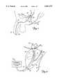
- FIG. 1is a vertical sectional view of a male pelvic region showing the urinary organs affected by benign prostatic hyperplasia.
- FIG. 2is an enlarged view of the male pelvic region of FIG. 1 showing a urethral catheter positioned within the prostate region.
- FIG. 3is a block diagram of the microwave energy delivery system for use with a urethral catheter according to the present invention.
- FIG. 4is a perspective view of the microwave energy delivery system for use with a urethral catheter according to the present invention.
- FIG. 5is a schematic diagram of the dual directional coupler provided in the microwave energy delivery system to enable precise detection of forward and reflected microwave power.
- FIG. 6is a diagram illustrating a tuning screw for use with the microwave energy delivery system of the present invention.
- FIG. 7is a top view illustrating a twisted wire gasket for providing a low inductance ground in the microwave energy delivery system of the present invention.
- FIG. 8is an exploded diagram illustrating the bottom portion of the dual directional coupler with channels formed therein for use in the microwave energy delivery system of the present invention.
- FIG. 1is a vertical section view of a male pelvic region showing the effect that benign prostatic hyperplasia (BPH) has on the urinary organs.
- Urethra 10is a duct leading from bladder 12, through prostate 14 and out orifice 16 of penis end 18. Benign tumorous tissue growth within prostate 14 around urethra 10 causes constriction 20 of urethra 10, which interrupts the flow of urine from bladder 12 to orifice 16.
- the tumorous tissue of prostate 14 which encroaches urethra 10 and causes constriction 20can be effectively removed by heating and necrosing the encroaching tumorous tissue.
- periurethral tumorous tissue of prostate 14 anterior and lateral to urethra 10is heated and necrosed to avoid unnecessary and undesirous damage to urethra 10 and to adjacent healthy tissues, such as ejaculatory duct 24 and rectum 26.
- a selective heating of benign tumorous tissue of prostate 14is made possible by a microwave antenna-containing catheter 28, insertable into urethra 10 as shown in FIG. 2.
- FIG. 2shows an enlarged view of the male pelvic region of FIG. 1 with catheter 28 properly positioned within urethra 10.
- Catheter 28includes retention balloon 30, end cap 38, and microwave antenna 32 connected to microwave generating source 36 by coaxial cable 34.
- Retention balloon 34is inflated through an inflation port and lumen extending through catheter 28, and serves to retain catheter 28 in a fixed position within urethra 10 when balloon 34 is inflated within bladder 12 near bladder neck 22.
- the balloon inflation lumenis sealed at the end of catheter 28 by end cap 38.
- microwave generating source 36delivers a driving signal through coaxial cable 34 to energize microwave antenna 32.
- microwave generating source 36produces a maximum of 100 watts of electrical power at about 915 MHz+/-13 MHz, which is within the U.S. FCC-ISM standards.
- antenna 32When antenna 32 is energized by microwave generating source 36, antenna 32 emits electromagnetic energy which causes heating of tissue within transition region 40 of prostate 14 due to molecular excitation.
- Catheter 28preferably includes a cooling system such as that described in U.S. Pat. No. 5,413,588, entitled DEVICE FOR ASYMMETRICAL THERMAL THERAPY WITH HELICAL DIPOLE MICROWAVE ANTENNA, which is hereby incorporated by reference.
- catheter 28preferably directs energy preferentially to maintain the temperature of tissue adjacent ejaculatory duct 24 and rectum 26 below about 45° C., and also preferably cools urethra 10 to avoid potential harmful effects to these tissues.
- an efficient microwave antennais critical to the ability to focus thermal energy a distance from the antenna within a target tissue volume.
- An inefficient antennaproduces a lesser intensity of microwave radiation within the target volume than desired. It also produces undesired heat close to the urethra along the antenna and associated transmission line, which will damage the urethra if not carried away by an increased coolant flow.
- This added burden on the cooling systemlimits its capacity to protect the urethra, thereby limiting the microwave power that can be radiated without elevating urethral temperatures above safety limits. With microwave power limited by cooling system capacity, the heat delivered to the desired target area of the prostate will not be sufficient for effective therapy.
- FIG. 3is a block diagram of a microwave energy delivery system for use with urethral catheter 28, according to the present invention.
- Microwave generating source 36includes 902-928 MHz generator 50, amplifier 52, isolator 54, low pass filter 56 and dual directional coupler 58.
- Amplifier 52steps up the signal from generator 50 to a level for delivering sufficient power to the microwave antenna for effective thermal therapy.
- Isolator 54is provided to protect generator 50 and amplifier 52 from high level reflected power signals, thereby preserving the circuitry in cases where sudden coupling changes occur and cause large reflected power signals, for example.
- Low pass filter 56attenuates high frequency harmonic signals, preferably by at least 30 dB, to ensure that those signals do not affect the performance of the microwave energy delivery system and antenna.
- Dual directional coupler 58detects forward and reflected power, and is connected to real time controller 60 which analyzes the forward and reflected power measurements and is operable to control the power and/or frequency of generator 50 based on the forward and reflected power measurements.
- Generator 50, amplifier 52, isolator 54 and low pass filter 56are implemented in a manner known in the art.
- Dual directional coupler 58is preferably implemented as shown in FIG. 5, so that forward and reflected power may be precisely detected.
- User interface 62is connected to real time controller 60, allowing a user to monitor the operation of the system and to input criteria and instructions for controlling the system via real time controller 60.
- FIG. 4is a perspective view of the microwave energy delivery system of the present invention.
- Amplifier 52, isolator 54 and low pass filter 56are implemented using microstrip architecture in a manner known in the art.
- low pass filter 56is implemented as a stepped impedance low pass filter, with transmission impedances selected to allow microstrip trace widths large enough to accommodate 100% reflected power, to account for the possibility of a fault condition.
- the microwave signal generated by generator 50is passed through amplifier 52, isolator 54 and low pass filter 56 and to dual directional coupler 58 by a 50-ohm microstrip transmission line conductor 70a.
- transmission line conductor 70a and surrounding dielectrics 72 and 74are designed so that microstrip transmission line 70a performs as a 50-ohm characteristic impedance coaxial cable, according to techniques known in the art.
- the transmission lineis then narrowed into transmission line 70b as it passes through dual directional coupler 58, which is implemented in a stripline architecture, having a conductor formed on a dielectric layer with another dielectric layer above, between two parallel ground planes, as is known in the art.
- Transmission line 70bis also designed according to techniques known in the art to perform as a 50-ohm characteristic impedance coaxial cable, and is narrower than microstrip transmission line 70a to account for the differences in performance characteristics between microstrip and stripline architectures.
- the microwave energy delivery systemis housed in chassis 76, with a microwave flat-to-round connector 78 providing an interface through chassis 76 between dual directional coupler 58 and coaxial cable 34.
- FIG. 5is a schematic diagram of dual directional coupler 58 for enabling precise detection of forward and reflected microwave power.
- Conductive trace 82runs parallel to transmission line conductor 70b for a length 84 equal to a quarter wavelength at the median microwave operating frequency (e.g. 915 MHz).
- the microwave signal on transmission line conductor 70bis coupled to conductive trace 82 across capacitive gap 86.
- the forward power signal on transmission line conductor 70bis coupled onto conductive trace 82 with a predetermined amount of attenuation, which is controlled by length 84 of conductive trace 82, gap 86 between transmission line conductor 70b and conductive trace 82, and width 88 of conductive trace 82, as is known in the art of high frequency coupler design.
- the coupling structureoperates to attenuate the coupled signal down to an appropriate level for measurement, and effectively blocks any reflected power signal from being coupled onto conductive trace 82, so that forward and reflected power measurements are substantially unaffected by each other.
- Diode detection circuit 90is connected to conductive trace 82, and operates to detect the forward power signal.
- a terminating resistortraditionally is selected to present an impedance matched to the characteristic impedance of transmission line 70b; however, terminating resistor 92 of the present invention is intentionally chosen to present an impedance mismatch to compensate for degradation effects associated with manufacturing variations in the coupling circuit. This design results in optimal directivity (a measure of separation between forward power measurements and reverse power measurements) and therefore precision in measuring forward power.
- conductive trace 102runs parallel to transmission line conductor 70b for a length 104 equal to a quarter wavelength at the median microwave operating frequency (e.g. 915 MHz).
- the microwave signal on transmission line conductor 70bis coupled to conductive trace 102 across capacitive gap 106.
- the reflected power signal on transmission line conductor 70bis coupled onto conductive trace 102 with a predetermined amount of attenuation, which is controlled by length 104 of conductive trace 102, gap 106 between transmission line conductor 70b and conductive trace 102, and width 108 of conductive trace 102, as is known in the art of high frequency coupler design.
- the coupling structureoperates to attenuate the coupled signal down to an appropriate level for measurement, and effectively blocks any forward power signal from being coupled onto conductive trace 102, so that reflected and forward power measurements are substantially unaffected by each other.
- Diode detection circuit 110is connected to conductive trace 102, and operates to detect the reflected power signal.
- terminating resistor 112 of the present inventionis intentionally chosen to present an impedance mismatch to compensate for degradation effects associated with manufacturing variations in the coupling circuit. This design results in optimal directivity and therefore precision in measuring reflected power.
- FIG. 6is a diagram illustrating the interface between dual directional coupler 58 and flat-to-round connector 78, implementing tuning screw 130 according to the present invention.
- Dual directional coupler 58includes transmission line conductor 70b formed on dielectric layer 122 with dielectric layer 124 above, between conductive ground planes 120 and 126.
- the layers of dual directional coupler 58are torqued together so that transmission line conductor 70b is effectively embossed into dielectric layers 122 and 124, to prevent air gaps between dielectric layers 122 and 124 due to the thickness of conducto70b.
- Dual directional coupler 58extends adjacent to the wall of chassis 76, with air gap 128 between dual directional coupler 58 and chassis wall 76.
- Connector 78includes conductive element 129 extending through chassis wall 76 to contact transmission line conductor 70b, to couple the microwave signal from transmission line conductor 70b to coaxial cable 34 (FIG. 4) for delivery to a microwave antenna in a treatment catheter.
- Air gap 128 between dual directional coupler 58 and chassis wall 76introduces a parasitic inductance and capacitance into the system, while the flat-to-circular transition at connector 78 introduces a parasitic inductance. While the ranges of these parasitic effects may be controlled, it is nearly impossible to control the manufacturing process tightly enough to consistently and precisely cancel the parasitics, which presents the potential for an impedance mismatch that would degrade the efficiency of microwave power delivery to the prostate. Additionally, it is possible for coaxial cable 34 (FIG. 4) to present a characteristic impedance that is not exactly 50 ohms, due to inexact manufacturing, which needs to be accounted for by the microwave energy delivery system if performance is to be optimized.
- the manufacturing processis controlled to ensure that the parasitic effects due to air gap 128 and the flat-to-circular transition of connector 78 result in a net parasitic inductance, and tuning screw 130 is provided to extend through ground conductor 126 into dielectric layer 124 to present an adjustable capacitance in the system to cancel the net parasitic inductance.
- the capacitanceis adjustable by simply turning screw 130 to change the depth that screw 130 extends into dielectric layer 124.
- the capacitanceis directly related to the distance between transmission line conductor 70b and the tip of screw 130.
- Mica insulator 132is preferably provided in dielectric layer 124 opposing the tip of screw 130 to protect against shorting between tuning screw 130 and transmission line conductor 70b; tuning screw 130 can be turned until it contacts insulator 132 adjacent transmission line conductor 70b.
- Insulator 132may alternatively be composed of an insulating material known in the art other than mica.
- calibration of the systemis initially performed while connecter 78 is connected to a standardized 50-ohm load termination, with tuning screw 130 being adjusted until 0% reflected power is achieved, and is then performed again with a patient cable in place to account for variations in the patient cable from the nominal 50-ohm characteristic impedance.
- tuning screw 130may be adjusted until the efficiency of the microwave antenna delivery system is maximized, providing the capability to achieve optimum impedance matching performance despite minor characteristic impedance variations in coaxial cable 34 and other components of the thermal therapy system.
- FIG. 7is a top view illustrating twisted wire gasket 150 positioned between dual-directional coupler 58 and chassis wall 76 to provide a low inductance ground in the microwave energy delivery system of the present invention.
- Twisted wire gasket 150may, for example, be a dual twist contact strip, part number 99-220-NT commercially available from Omega Shielding Products. Twisted wire gasket 150 contacts the metal surfaces (conductors 120 and 126, FIG. 6) of dual directional coupler 58 and also the metal surface of chassis wall 76, effectively "gouging" into those metal surfaces and thereby achieving superior contact between them. This is desirable to reduce the noise associated with the ground of the microwave energy delivery system due to inductance in ground connections.
- Chassis wall 76 and outer conductors 120 and 126 (FIG. 6) of dual directional coupler 58are grounded, so that the low inductance connection between them provided by twisted wire gasket 150 is beneficial to reduce the noise level associated with the ground of the system, thereby improving the sensitivity and overall performance of the system.
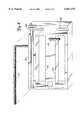
- FIG. 8is an exploded diagram illustrating the bottom portion of dual directional coupler 58 with channels 160, 162, 164 and 166 formed therein for use in the microwave energy delivery system of the present invention.
- Channels 160 and 162are formed with sufficient depth to house diode detection circuits 90 and 110 (FIG. 5), which may be realized on a conventional PC board, for example, or by other well-known circuit construction technologies.
- Corresponding channelsare formed in the top portion of dual directional coupler 58 opposite channels 160 and 162, thereby forming recessed cavities within the body of dual directional coupler 58 that effectively shield diode detection circuits 90 and 110 (FIG. 5) from external noise, improving their sensitivity and overall performance.
- Channels 164 and 166are formed with a width and depth to enable wire mesh pieces 170 to be inserted therein.
- Wire mesh pieces 170may, for example, be hollow core round ultraflex electronic beryllium copper knitted wire shielding pieces, part number 8101-0104-40 (0.156 inch diameter) commercially available from Instrument Specialties.
- Wire mesh pieces 170are preferably inserted into channels 164 and 166 so that there is a slight crest of mesh material above the top of the channels.
- Wire mesh pieces 170 inserted in channels 164 and 166improve the electrical connection between the top and bottom portions of dual directional coupler 58, specifically between ground plane conductors 120 and 126 (FIG. 6), improving the grounding distribution properties and thereby improving the sensitivity and overall performance of dual directional coupler 58.
- the present inventiontherefore provides a microwave energy delivery system having the capability to precisely detect both forward power delivered to a microwave antenna and reverse power reflected from the microwave antenna.
- a dual directional couplerwhich is preferably connected to a real time controller to analyze the forward and reflected power measurements.
- the dual directional couplerincludes a first quarter wavelength coupling circuit to detect forward power signals on the main transmission line and second quarter wavelength coupling circuit to detect reflected power signals from the transmission line. Terminating resistors for each coupling circuit are selected to have impedances that are mismatched from the characteristic impedance of the transmission line to optimize the directivity of the dual directional coupler.
- the dual directional coupleris preferably tunable to optimize the impedance match and thereby performance of the system.
- a twisted wire gasket and wire mesh piecesare preferably utilized in association with the dual directional coupler to improve the ground distribution of the system.
- a dual-directional coupler constructed as described abovewas implemented in a microwave energy delivery system and tested at a center frequency of 915 MHz, yielding the results shown in Table 1.
- the Terminating Resistor Valuesrepresent the values of terminating resistors 92 and 112 (FIG. 5).
- the Through-Line Power valuerepresents the reduction in power delivered on transmission line conductor 70b due to coupling by dual-directional coupler 58.
- the Coupling valuerepresents the ratio of the coupled power signal on traces 82 and 102 to the delivered power signal on transmission line conductor 70b.
- the Isolation valuerepresents the ratio of a voltage signal representing the undesired power signal to a voltage signal representing the desired power signal; that is, the ratio of a reflected power voltage signal to a forward power voltage signal in the forward power detection circuit, and the ration of a forward power voltage signal to a reflected power voltage signal in the reflected power detection circuit.
- Terminating Resistor Values of 47.5 ohmsyielded the greatest Isolation in the dual-directional coupler tested.
- An Isolation value of -40 dBrepresents an uncertainty of 1%, meaning that a reflected power signal (in the forward power detection circuit) has a magnitude that is attenuated to 1% of its actual (coupled) magnitude while the forward power signal has its 100% full (coupled) magnitude, and vice versa for the forward power signal in the reflected power detection circuit.
- the microwave energy delivery system of the present inventionis able to utilize precise forward and reflected power measurements to perform a variety of control functions, thereby optimizing the performance of the system in a thermal therapy treatment session.
Landscapes
- Health & Medical Sciences (AREA)
- Surgery (AREA)
- Life Sciences & Earth Sciences (AREA)
- Biomedical Technology (AREA)
- Medical Informatics (AREA)
- Nuclear Medicine, Radiotherapy & Molecular Imaging (AREA)
- Electromagnetism (AREA)
- Engineering & Computer Science (AREA)
- Physics & Mathematics (AREA)
- Heart & Thoracic Surgery (AREA)
- Otolaryngology (AREA)
- Molecular Biology (AREA)
- Animal Behavior & Ethology (AREA)
- General Health & Medical Sciences (AREA)
- Public Health (AREA)
- Veterinary Medicine (AREA)
- Surgical Instruments (AREA)
Abstract
Description
TABLE 1 ______________________________________ Terminating Through-Line Resistor Values Power Coupling Isolation ______________________________________ 49.9 ohms -0.08 dB -26.5 dB -41.4 dB 47.5 ohms -0.08 dB -26.1 dB -45.6 dB 43.1 ohms -0.08 dB -25.8 dB -40.0 dB ______________________________________
Claims (19)
Priority Applications (1)
| Application Number | Priority Date | Filing Date | Title |
|---|---|---|---|
| US09/186,795US6067475A (en) | 1998-11-05 | 1998-11-05 | Microwave energy delivery system including high performance dual directional coupler for precisely measuring forward and reverse microwave power during thermal therapy |
Applications Claiming Priority (1)
| Application Number | Priority Date | Filing Date | Title |
|---|---|---|---|
| US09/186,795US6067475A (en) | 1998-11-05 | 1998-11-05 | Microwave energy delivery system including high performance dual directional coupler for precisely measuring forward and reverse microwave power during thermal therapy |
Publications (1)
| Publication Number | Publication Date |
|---|---|
| US6067475Atrue US6067475A (en) | 2000-05-23 |
Family
ID=22686317
Family Applications (1)
| Application Number | Title | Priority Date | Filing Date |
|---|---|---|---|
| US09/186,795Expired - LifetimeUS6067475A (en) | 1998-11-05 | 1998-11-05 | Microwave energy delivery system including high performance dual directional coupler for precisely measuring forward and reverse microwave power during thermal therapy |
Country Status (1)
| Country | Link |
|---|---|
| US (1) | US6067475A (en) |
Cited By (78)
| Publication number | Priority date | Publication date | Assignee | Title |
|---|---|---|---|---|
| US20040220557A1 (en)* | 2003-04-30 | 2004-11-04 | Eum Jay J. | Closed system warming catheter and method of use |
| US20050045723A1 (en)* | 2003-08-29 | 2005-03-03 | Zih Corp. | Spatially Selective UHF Near Field Microstrip Coupler Device and RFID Systems Using Device |
| US6866624B2 (en)* | 2000-12-08 | 2005-03-15 | Medtronic Ave,Inc. | Apparatus and method for treatment of malignant tumors |
| US20050149010A1 (en)* | 2003-07-18 | 2005-07-07 | Vivant Medical, Inc. | Devices and methods for cooling microwave antennas |
| US20050274799A1 (en)* | 2004-06-10 | 2005-12-15 | Zih Corp. | Apparatus and method for communicating with an RFID transponder |
| US20060015093A1 (en)* | 2003-01-04 | 2006-01-19 | Endocare, Inc. | Open system heat exchange catheters and methods of use |
| US20060142752A1 (en)* | 2001-11-29 | 2006-06-29 | Ormsby Theodore C | Radio-frequency-based catheter system with improved deflection and steering mechanisms |
| US20060282039A1 (en)* | 2005-06-09 | 2006-12-14 | Endocare, Inc. | Heat exchange catheter with multi-lumen tube having a fluid return passageway |
| US20060287649A1 (en)* | 1998-12-14 | 2006-12-21 | Ormsby Theodore C | Radio-frequency based catheter system and method for ablating biological tissues |
| US20070005050A1 (en)* | 2005-06-09 | 2007-01-04 | Endocare, Inc. | Heat exchange catheter and method of use |
| US20070016180A1 (en)* | 2004-04-29 | 2007-01-18 | Lee Fred T Jr | Microwave surgical device |
| US20070016181A1 (en)* | 2004-04-29 | 2007-01-18 | Van Der Weide Daniel W | Microwave tissue resection tool |
| US20070049918A1 (en)* | 2005-08-24 | 2007-03-01 | Van Der Weide Daniel W | Microwave device for vascular ablation |
| US20070078453A1 (en)* | 2005-10-04 | 2007-04-05 | Johnson Kristin D | System and method for performing cardiac ablation |
| US20070093880A1 (en)* | 2005-10-06 | 2007-04-26 | Boston Scientific Scimed, Inc. | Adjustable profile probe |
| US20070112392A1 (en)* | 2005-11-15 | 2007-05-17 | Alon Konchitsky | Microwave energy head therapy |
| US7258688B1 (en) | 2002-04-16 | 2007-08-21 | Baylis Medical Company Inc. | Computerized electrical signal generator |
| US20070288079A1 (en)* | 2006-03-24 | 2007-12-13 | Micrablate | Energy delivery system and uses thereof |
| US20080015570A1 (en)* | 1998-12-14 | 2008-01-17 | Ormsby Theodore C | Hollow conductive coaxial cable for radio frequency based tissue ablation system |
| US20080119921A1 (en)* | 2004-04-29 | 2008-05-22 | Micrablate | Air-core microwave ablation antennas |
| US20080147056A1 (en)* | 2006-07-14 | 2008-06-19 | Micrablate | Energy delivery systems and uses thereof |
| US20080197976A1 (en)* | 2000-02-28 | 2008-08-21 | Littlechild Stuart Colin | Radio frequency identification transponder |
| US7467015B2 (en) | 2004-04-29 | 2008-12-16 | Neuwave Medical, Inc. | Segmented catheter for tissue ablation |
| US20090061681A1 (en)* | 2007-09-05 | 2009-03-05 | Mcmunigal Tom | Electrical receptacle assembly |
| EP2036512A1 (en)* | 2007-09-13 | 2009-03-18 | Vivant Medical, Inc. | Frequency tuning in a microwave electrosurgical system |
| US20090152353A1 (en)* | 2007-12-18 | 2009-06-18 | Zih Corp. | Rfid near-field antenna and associated systems |
| US20100036369A1 (en)* | 2006-12-08 | 2010-02-11 | Bangor University | Microwave array applicator for hyperthermia |
| US20100057070A1 (en)* | 2008-09-03 | 2010-03-04 | Vivant Medical, Inc. | Microwave Shielding Apparatus |
| US20100057076A1 (en)* | 2008-09-03 | 2010-03-04 | Vivant Medical, Inc. | Shielding for an Isolation Apparatus Used in a Microwave Generator |
| US20100082022A1 (en)* | 2008-09-30 | 2010-04-01 | Haley Kaylen J | Delivered energy generator for microwave ablation |
| US20100082084A1 (en)* | 2008-09-30 | 2010-04-01 | Brannan Joseph D | Microwave system calibration apparatus and method of use |
| US20100079215A1 (en)* | 2008-09-30 | 2010-04-01 | Brannan Joseph D | System, apparatus and method for dissipating standing wave in a microwave delivery system |
| US20100082023A1 (en)* | 2008-09-30 | 2010-04-01 | Brannan Joseph D | Microwave system calibration apparatus, system and method of use |
| US20100082083A1 (en)* | 2008-09-30 | 2010-04-01 | Brannan Joseph D | Microwave system tuner |
| US20100082025A1 (en)* | 2008-09-30 | 2010-04-01 | Brannan Joseph D | Microwave ablation generator control system |
| US20100082024A1 (en)* | 2008-09-30 | 2010-04-01 | Brannan Joseph D | Intermittent microwave energy delivery system |
| US20100097284A1 (en)* | 2008-10-17 | 2010-04-22 | Vivant Medical, Inc. | Choked Dielectric Loaded Tip Dipole Microwave Antenna |
| US20100268218A1 (en)* | 2009-04-15 | 2010-10-21 | Medwaves, Inc. | Electrically Tunable Tissue Ablation system and Method |
| US20100286679A1 (en)* | 2009-04-27 | 2010-11-11 | Michael Hoey | Systems and Methods for Prostate Treatment |
| US20100286686A1 (en)* | 2007-09-25 | 2010-11-11 | Christopher Paul Hancock | Surgical resection apparatus |
| US20110066144A1 (en)* | 2009-09-16 | 2011-03-17 | Vivant Medical, Inc. | Perfused Core Dielectrically Loaded Dipole Microwave Antenna Probe |
| US20110098697A1 (en)* | 2009-10-28 | 2011-04-28 | Vivant Medical, Inc. | System and Method for Monitoring Ablation Size |
| EP2363088A1 (en)* | 2010-03-01 | 2011-09-07 | Vivant Medical, Inc. | Sensors on patient side for a microwave generator |
| US20110218527A1 (en)* | 2010-03-08 | 2011-09-08 | Vivant Medical, Inc. | Microwave Antenna Probe Having a Deployable Ground Plane |
| US8152800B2 (en) | 2007-07-30 | 2012-04-10 | Vivant Medical, Inc. | Electrosurgical systems and printed circuit boards for use therewith |
| US20120103973A1 (en)* | 2010-10-29 | 2012-05-03 | Goji Ltd. | Time Estimation for Energy Application in an RF Energy Transfer Device |
| US20120143180A1 (en)* | 2004-04-29 | 2012-06-07 | Neuwave Medical, Inc. | Triaxial antenna for microwave tissue ablation |
| US20120152938A1 (en)* | 2010-12-21 | 2012-06-21 | Whirlpool Corporation | Control of microwave source efficiency in a microwave heating apparatus |
| US8298223B2 (en) | 2003-05-01 | 2012-10-30 | Covidien Ag | Method and system for programming and controlling an electrosurgical generator system |
| WO2013149245A1 (en) | 2012-03-31 | 2013-10-03 | Microcube, Llc | Returned power for microwave applications |
| US8672932B2 (en) | 2006-03-24 | 2014-03-18 | Neuwave Medical, Inc. | Center fed dipole for use with tissue ablation systems, devices and methods |
| US8740893B2 (en) | 2010-06-30 | 2014-06-03 | Covidien Lp | Adjustable tuning of a dielectrically loaded loop antenna |
| US9119649B2 (en) | 2009-07-28 | 2015-09-01 | Neuwave Medical, Inc. | Energy delivery systems and uses thereof |
| US9192438B2 (en) | 2011-12-21 | 2015-11-24 | Neuwave Medical, Inc. | Energy delivery systems and uses thereof |
| US9198708B2 (en) | 2010-03-25 | 2015-12-01 | Nxthera, Inc. | Systems and methods for prostate treatment |
| US9345507B2 (en) | 2008-11-06 | 2016-05-24 | Nxthera, Inc. | Systems and methods for treatment of BPH |
| US20160169950A1 (en)* | 2014-12-12 | 2016-06-16 | Ametek Power Instruments | Frequency selective power monitor |
| US9861424B2 (en) | 2007-07-11 | 2018-01-09 | Covidien Lp | Measurement and control systems and methods for electrosurgical procedures |
| US9861440B2 (en) | 2010-05-03 | 2018-01-09 | Neuwave Medical, Inc. | Energy delivery systems and uses thereof |
| US9895185B2 (en) | 2011-09-13 | 2018-02-20 | Nxthera, Inc. | Systems and methods for prostate treatment |
| US9968395B2 (en) | 2013-12-10 | 2018-05-15 | Nxthera, Inc. | Systems and methods for treating the prostate |
| US10194970B2 (en) | 2013-12-10 | 2019-02-05 | Nxthera, Inc. | Vapor ablation systems and methods |
| US10335222B2 (en) | 2012-04-03 | 2019-07-02 | Nxthera, Inc. | Induction coil vapor generator |
| US10342593B2 (en) | 2015-01-29 | 2019-07-09 | Nxthera, Inc. | Vapor ablation systems and methods |
| US10363092B2 (en) | 2006-03-24 | 2019-07-30 | Neuwave Medical, Inc. | Transmission line with heat transfer ability |
| US10531917B2 (en) | 2016-04-15 | 2020-01-14 | Neuwave Medical, Inc. | Systems and methods for energy delivery |
| US10610281B2 (en) | 2008-11-06 | 2020-04-07 | Boston Scientific Scimed, Inc. | Systems and methods for treatment of prostatic tissue |
| US10667528B2 (en) | 2010-07-01 | 2020-06-02 | Goji Limited | Processing objects by radio frequency (RF) energy |
| US10702327B2 (en) | 2015-05-13 | 2020-07-07 | Boston Scientific Scimed, Inc. | Systems and methods for treating the bladder with condensable vapor |
| US10751107B2 (en) | 2017-01-06 | 2020-08-25 | Boston Scientific Scimed, Inc. | Transperineal vapor ablation systems and methods |
| US10772670B2 (en) | 2013-03-14 | 2020-09-15 | Boston Scientific Scimed, Inc. | Systems and methods for treating prostate cancer |
| US10952792B2 (en) | 2015-10-26 | 2021-03-23 | Neuwave Medical, Inc. | Energy delivery systems and uses thereof |
| WO2022003335A1 (en)* | 2020-07-01 | 2022-01-06 | Emblation Limited | Optimally integrated generator antenna system |
| US11246640B2 (en) | 2016-12-21 | 2022-02-15 | Boston Scientific Scimed, Inc. | Vapor ablation systems and methods |
| US11389235B2 (en) | 2006-07-14 | 2022-07-19 | Neuwave Medical, Inc. | Energy delivery systems and uses thereof |
| US11672596B2 (en) | 2018-02-26 | 2023-06-13 | Neuwave Medical, Inc. | Energy delivery devices with flexible and adjustable tips |
| US11832879B2 (en) | 2019-03-08 | 2023-12-05 | Neuwave Medical, Inc. | Systems and methods for energy delivery |
| US12440258B2 (en) | 2023-11-20 | 2025-10-14 | Boston Scientific Scimed, Inc. | Systems and methods for treating prostate cancer |
Citations (3)
| Publication number | Priority date | Publication date | Assignee | Title |
|---|---|---|---|---|
| US4557272A (en)* | 1980-03-31 | 1985-12-10 | Microwave Associates, Inc. | Microwave endoscope detection and treatment system |
| US5027829A (en)* | 1986-12-15 | 1991-07-02 | Larsen Lawrence E | Apparatus for diathermy treatment and control |
| US5957969A (en)* | 1993-05-14 | 1999-09-28 | Fidus Medical Technology Corporation | Tunable microwave ablation catheter system and method |
- 1998
- 1998-11-05USUS09/186,795patent/US6067475A/ennot_activeExpired - Lifetime
Patent Citations (3)
| Publication number | Priority date | Publication date | Assignee | Title |
|---|---|---|---|---|
| US4557272A (en)* | 1980-03-31 | 1985-12-10 | Microwave Associates, Inc. | Microwave endoscope detection and treatment system |
| US5027829A (en)* | 1986-12-15 | 1991-07-02 | Larsen Lawrence E | Apparatus for diathermy treatment and control |
| US5957969A (en)* | 1993-05-14 | 1999-09-28 | Fidus Medical Technology Corporation | Tunable microwave ablation catheter system and method |
Cited By (199)
| Publication number | Priority date | Publication date | Assignee | Title |
|---|---|---|---|---|
| US20060287649A1 (en)* | 1998-12-14 | 2006-12-21 | Ormsby Theodore C | Radio-frequency based catheter system and method for ablating biological tissues |
| US7594913B2 (en)* | 1998-12-14 | 2009-09-29 | Medwaves, Inc. | Radio-frequency based catheter system and method for ablating biological tissues |
| US20080015570A1 (en)* | 1998-12-14 | 2008-01-17 | Ormsby Theodore C | Hollow conductive coaxial cable for radio frequency based tissue ablation system |
| US8308722B2 (en) | 1998-12-14 | 2012-11-13 | Medwaves, Inc. | Hollow conductive coaxial cable for radio frequency based tissue ablation system |
| US20080197976A1 (en)* | 2000-02-28 | 2008-08-21 | Littlechild Stuart Colin | Radio frequency identification transponder |
| US6866624B2 (en)* | 2000-12-08 | 2005-03-15 | Medtronic Ave,Inc. | Apparatus and method for treatment of malignant tumors |
| US20060142752A1 (en)* | 2001-11-29 | 2006-06-29 | Ormsby Theodore C | Radio-frequency-based catheter system with improved deflection and steering mechanisms |
| US8152799B2 (en) | 2001-11-29 | 2012-04-10 | Medwaves, Inc. | Radio frequency-based catheter system with improved deflection and steering mechanisms |
| US20110009858A1 (en)* | 2001-11-29 | 2011-01-13 | Medwaves, Inc. | Radio frequency-based catheter system with improved deflection and steering mechanisms |
| US7815637B2 (en) | 2001-11-29 | 2010-10-19 | Ormsby Theodore C | Radio-frequency-based catheter system with improved deflection and steering mechanisms |
| US20070282321A1 (en)* | 2002-04-16 | 2007-12-06 | Baylis Medical Company Inc. | Computerized electrical signal generator |
| US11147608B2 (en) | 2002-04-16 | 2021-10-19 | Baylis Medical Company Inc. | Computerized electrical signal generator |
| US7258688B1 (en) | 2002-04-16 | 2007-08-21 | Baylis Medical Company Inc. | Computerized electrical signal generator |
| US20060015093A1 (en)* | 2003-01-04 | 2006-01-19 | Endocare, Inc. | Open system heat exchange catheters and methods of use |
| US20050021014A1 (en)* | 2003-04-30 | 2005-01-27 | Eum Jay J. | Closed system warming catheter and method of use |
| US20040220557A1 (en)* | 2003-04-30 | 2004-11-04 | Eum Jay J. | Closed system warming catheter and method of use |
| US8298223B2 (en) | 2003-05-01 | 2012-10-30 | Covidien Ag | Method and system for programming and controlling an electrosurgical generator system |
| US9820814B2 (en) | 2003-07-18 | 2017-11-21 | Covidien Lp | Devices and methods for cooling microwave antennas |
| US10405921B2 (en) | 2003-07-18 | 2019-09-10 | Covidien Lp | Devices and methods for cooling microwave antennas |
| US20080135217A1 (en)* | 2003-07-18 | 2008-06-12 | Roman Turovskiy | Devices and Methods for Cooling Microwave Antennas |
| US9468499B2 (en) | 2003-07-18 | 2016-10-18 | Covidien Lp | Devices and methods for cooling microwave antennas |
| US20050149010A1 (en)* | 2003-07-18 | 2005-07-07 | Vivant Medical, Inc. | Devices and methods for cooling microwave antennas |
| US9480528B2 (en) | 2003-07-18 | 2016-11-01 | Covidien Lp | Devices and methods for cooling microwave antennas |
| US7650114B2 (en)* | 2003-08-29 | 2010-01-19 | Zih Corp. | Spatially selective UHF near field microstrip coupler device and RFID systems using device |
| US20050045723A1 (en)* | 2003-08-29 | 2005-03-03 | Zih Corp. | Spatially Selective UHF Near Field Microstrip Coupler Device and RFID Systems Using Device |
| US7398054B2 (en)* | 2003-08-29 | 2008-07-08 | Zih Corp. | Spatially selective UHF near field microstrip coupler device and RFID systems using device |
| US8351959B2 (en) | 2003-08-29 | 2013-01-08 | Zih Corp. | Spatially selective UHF near field microstrip coupler device and RFID systems using device |
| US9852318B2 (en) | 2003-08-29 | 2017-12-26 | Zih Corp. | Spatially selective UHF near field microstrip coupler device and RFID systems using device |
| US8160493B2 (en) | 2003-08-29 | 2012-04-17 | Zih Corp. | Spatially selective UHF near field microstrip coupler device and RFID systems using device |
| US20090008448A1 (en)* | 2003-08-29 | 2009-01-08 | Zih Corp. | Spatially selective uhf near field microstrip coupler device and rfid systems using device |
| US20070016181A1 (en)* | 2004-04-29 | 2007-01-18 | Van Der Weide Daniel W | Microwave tissue resection tool |
| US20070016180A1 (en)* | 2004-04-29 | 2007-01-18 | Lee Fred T Jr | Microwave surgical device |
| US7467015B2 (en) | 2004-04-29 | 2008-12-16 | Neuwave Medical, Inc. | Segmented catheter for tissue ablation |
| US20120143180A1 (en)* | 2004-04-29 | 2012-06-07 | Neuwave Medical, Inc. | Triaxial antenna for microwave tissue ablation |
| US20070055224A1 (en)* | 2004-04-29 | 2007-03-08 | Lee Fred T Jr | Intralumenal microwave device |
| US10342614B2 (en) | 2004-04-29 | 2019-07-09 | Wisconsin Alumni Research Foundation | Triaxial antenna for microwave tissue ablation |
| US20080119921A1 (en)* | 2004-04-29 | 2008-05-22 | Micrablate | Air-core microwave ablation antennas |
| US8544740B2 (en) | 2004-06-10 | 2013-10-01 | Zih Corp. | Apparatus and method for communicating with an RFID transponder |
| US20050274799A1 (en)* | 2004-06-10 | 2005-12-15 | Zih Corp. | Apparatus and method for communicating with an RFID transponder |
| US8596532B2 (en) | 2004-06-10 | 2013-12-03 | Zih Corp. | Apparatus and method for communicating with an RFID transponder |
| US9613242B2 (en) | 2004-06-10 | 2017-04-04 | Zih Corp. | Apparatus and method for communicating with an RFID transponder |
| US20060282039A1 (en)* | 2005-06-09 | 2006-12-14 | Endocare, Inc. | Heat exchange catheter with multi-lumen tube having a fluid return passageway |
| US7621889B2 (en) | 2005-06-09 | 2009-11-24 | Endocare, Inc. | Heat exchange catheter and method of use |
| US7621890B2 (en) | 2005-06-09 | 2009-11-24 | Endocare, Inc. | Heat exchange catheter with multi-lumen tube having a fluid return passageway |
| US20070005050A1 (en)* | 2005-06-09 | 2007-01-04 | Endocare, Inc. | Heat exchange catheter and method of use |
| US20070049918A1 (en)* | 2005-08-24 | 2007-03-01 | Van Der Weide Daniel W | Microwave device for vascular ablation |
| US20070078453A1 (en)* | 2005-10-04 | 2007-04-05 | Johnson Kristin D | System and method for performing cardiac ablation |
| US20070093880A1 (en)* | 2005-10-06 | 2007-04-26 | Boston Scientific Scimed, Inc. | Adjustable profile probe |
| US8123705B2 (en) | 2005-10-06 | 2012-02-28 | Boston Scientific Scimed, Inc. | Adjustable profile probe |
| US20070112392A1 (en)* | 2005-11-15 | 2007-05-17 | Alon Konchitsky | Microwave energy head therapy |
| US7548779B2 (en) | 2005-11-15 | 2009-06-16 | Alon Konchitsky | Microwave energy head therapy |
| US11944376B2 (en) | 2006-03-24 | 2024-04-02 | Neuwave Medical, Inc. | Transmission line with heat transfer ability |
| US10363092B2 (en) | 2006-03-24 | 2019-07-30 | Neuwave Medical, Inc. | Transmission line with heat transfer ability |
| US8672932B2 (en) | 2006-03-24 | 2014-03-18 | Neuwave Medical, Inc. | Center fed dipole for use with tissue ablation systems, devices and methods |
| US20070288079A1 (en)* | 2006-03-24 | 2007-12-13 | Micrablate | Energy delivery system and uses thereof |
| WO2008005668A3 (en)* | 2006-06-30 | 2008-10-30 | Medwaves Inc | Radio-frequency based catheter system and method for ablating biological tissues |
| CN101484083B (en)* | 2006-06-30 | 2012-02-01 | 麦迪威公司 | Radio-frequency based catheter system and method for ablating biological tissues |
| US11576722B2 (en) | 2006-07-14 | 2023-02-14 | Neuwave Medical, Inc. | Energy delivery systems and uses thereof |
| US11389235B2 (en) | 2006-07-14 | 2022-07-19 | Neuwave Medical, Inc. | Energy delivery systems and uses thereof |
| US20080147056A1 (en)* | 2006-07-14 | 2008-06-19 | Micrablate | Energy delivery systems and uses thereof |
| US10376314B2 (en) | 2006-07-14 | 2019-08-13 | Neuwave Medical, Inc. | Energy delivery systems and uses thereof |
| US11576723B2 (en) | 2006-07-14 | 2023-02-14 | Neuwave Medical, Inc. | Energy delivery systems and uses thereof |
| US11596474B2 (en) | 2006-07-14 | 2023-03-07 | Neuwave Medical, Inc. | Energy delivery systems and uses thereof |
| US20100036369A1 (en)* | 2006-12-08 | 2010-02-11 | Bangor University | Microwave array applicator for hyperthermia |
| US9861424B2 (en) | 2007-07-11 | 2018-01-09 | Covidien Lp | Measurement and control systems and methods for electrosurgical procedures |
| US9190704B2 (en) | 2007-07-30 | 2015-11-17 | Covidien Lp | Electrosurgical systems and printed circuit boards for use therewith |
| US8152800B2 (en) | 2007-07-30 | 2012-04-10 | Vivant Medical, Inc. | Electrosurgical systems and printed circuit boards for use therewith |
| US20090061681A1 (en)* | 2007-09-05 | 2009-03-05 | Mcmunigal Tom | Electrical receptacle assembly |
| US7645142B2 (en) | 2007-09-05 | 2010-01-12 | Vivant Medical, Inc. | Electrical receptacle assembly |
| EP2036512A1 (en)* | 2007-09-13 | 2009-03-18 | Vivant Medical, Inc. | Frequency tuning in a microwave electrosurgical system |
| JP2009066415A (en)* | 2007-09-13 | 2009-04-02 | Vivant Medical Inc | Frequency tuning in microwave electrosurgical systems |
| US20090076492A1 (en)* | 2007-09-13 | 2009-03-19 | Robert Behnke | Frequency tuning in a microwave electrosurgical system |
| EP3025663A1 (en)* | 2007-09-13 | 2016-06-01 | Covidien LP | Frequency tuning in a microwave electrosurgical system |
| US9498285B2 (en) | 2007-09-13 | 2016-11-22 | Covidien Lp | Impedance matching in a microwave electrosurgical system |
| US8747398B2 (en)* | 2007-09-13 | 2014-06-10 | Covidien Lp | Frequency tuning in a microwave electrosurgical system |
| AU2008212053B2 (en)* | 2007-09-13 | 2013-02-21 | Covidien Lp | Frequency tuning in a microwave electrosurgical system |
| US9707037B2 (en) | 2007-09-25 | 2017-07-18 | Creo Medical Limited | Surgical resection apparatus |
| US8795267B2 (en)* | 2007-09-25 | 2014-08-05 | Creo Medical Limited | Surgical resection apparatus |
| US11065054B2 (en) | 2007-09-25 | 2021-07-20 | Creo Medical Limited | Surgical resection apparatus |
| US20100286686A1 (en)* | 2007-09-25 | 2010-11-11 | Christopher Paul Hancock | Surgical resection apparatus |
| US9108434B2 (en) | 2007-12-18 | 2015-08-18 | Zih Corp. | RFID near-field antenna and associated systems |
| US20090152353A1 (en)* | 2007-12-18 | 2009-06-18 | Zih Corp. | Rfid near-field antenna and associated systems |
| US20100057070A1 (en)* | 2008-09-03 | 2010-03-04 | Vivant Medical, Inc. | Microwave Shielding Apparatus |
| US20100057076A1 (en)* | 2008-09-03 | 2010-03-04 | Vivant Medical, Inc. | Shielding for an Isolation Apparatus Used in a Microwave Generator |
| US8394086B2 (en) | 2008-09-03 | 2013-03-12 | Vivant Medical, Inc. | Microwave shielding apparatus |
| US8403924B2 (en) | 2008-09-03 | 2013-03-26 | Vivant Medical, Inc. | Shielding for an isolation apparatus used in a microwave generator |
| US9254172B2 (en) | 2008-09-03 | 2016-02-09 | Covidien Lp | Shielding for an isolation apparatus used in a microwave generator |
| US8174267B2 (en) | 2008-09-30 | 2012-05-08 | Vivant Medical, Inc. | Intermittent microwave energy delivery system |
| US8346370B2 (en) | 2008-09-30 | 2013-01-01 | Vivant Medical, Inc. | Delivered energy generator for microwave ablation |
| US20100082083A1 (en)* | 2008-09-30 | 2010-04-01 | Brannan Joseph D | Microwave system tuner |
| US8542019B2 (en) | 2008-09-30 | 2013-09-24 | Covidien Lp | Microwave ablation generator control system |
| US10070922B2 (en) | 2008-09-30 | 2018-09-11 | Covidien Lp | Microwave ablation generator control system |
| US20100079215A1 (en)* | 2008-09-30 | 2010-04-01 | Brannan Joseph D | System, apparatus and method for dissipating standing wave in a microwave delivery system |
| US20100082084A1 (en)* | 2008-09-30 | 2010-04-01 | Brannan Joseph D | Microwave system calibration apparatus and method of use |
| US8797039B2 (en) | 2008-09-30 | 2014-08-05 | Covidien Lp | Microwave ablation generator control system |
| US20100082022A1 (en)* | 2008-09-30 | 2010-04-01 | Haley Kaylen J | Delivered energy generator for microwave ablation |
| US20100082023A1 (en)* | 2008-09-30 | 2010-04-01 | Brannan Joseph D | Microwave system calibration apparatus, system and method of use |
| US10743935B2 (en) | 2008-09-30 | 2020-08-18 | Covidien Lp | Microwave ablation generator control system |
| US8287527B2 (en) | 2008-09-30 | 2012-10-16 | Vivant Medical, Inc. | Microwave system calibration apparatus and method of use |
| US20100082025A1 (en)* | 2008-09-30 | 2010-04-01 | Brannan Joseph D | Microwave ablation generator control system |
| US9526576B2 (en) | 2008-09-30 | 2016-12-27 | Covidien Lp | Microwave ablation generator control system |
| US8248075B2 (en) | 2008-09-30 | 2012-08-21 | Vivant Medical, Inc. | System, apparatus and method for dissipating standing wave in a microwave delivery system |
| US8242782B2 (en) | 2008-09-30 | 2012-08-14 | Vivant Medical, Inc. | Microwave ablation generator control system |
| US20100082024A1 (en)* | 2008-09-30 | 2010-04-01 | Brannan Joseph D | Intermittent microwave energy delivery system |
| US8180433B2 (en) | 2008-09-30 | 2012-05-15 | Vivant Medical, Inc. | Microwave system calibration apparatus, system and method of use |
| US9113924B2 (en) | 2008-10-17 | 2015-08-25 | Covidien Lp | Choked dielectric loaded tip dipole microwave antenna |
| US10188460B2 (en) | 2008-10-17 | 2019-01-29 | Covidien Lp | Choked dielectric loaded tip dipole microwave antenna |
| US20100097284A1 (en)* | 2008-10-17 | 2010-04-22 | Vivant Medical, Inc. | Choked Dielectric Loaded Tip Dipole Microwave Antenna |
| US11564727B2 (en) | 2008-11-06 | 2023-01-31 | Boston Scientific Scimed, Inc. | Systems and methods for treatment of prostatic tissue |
| US10610281B2 (en) | 2008-11-06 | 2020-04-07 | Boston Scientific Scimed, Inc. | Systems and methods for treatment of prostatic tissue |
| US12303181B2 (en) | 2008-11-06 | 2025-05-20 | Boston Scientific Scimed, Inc. | Systems and methods for treatment of prostatic tissue |
| US9345507B2 (en) | 2008-11-06 | 2016-05-24 | Nxthera, Inc. | Systems and methods for treatment of BPH |
| US9326819B2 (en) | 2009-04-15 | 2016-05-03 | Medwaves, Inc. | Electrically tunable tissue ablation system and method |
| US20100268218A1 (en)* | 2009-04-15 | 2010-10-21 | Medwaves, Inc. | Electrically Tunable Tissue Ablation system and Method |
| US10390873B2 (en) | 2009-04-27 | 2019-08-27 | Boston Scientific Scimed, Inc. | Systems and methods for prostate treatment |
| US11331135B2 (en) | 2009-04-27 | 2022-05-17 | Boston Scientific Scimed, Inc. | Systems and methods for prostate treatment |
| US12419678B2 (en) | 2009-04-27 | 2025-09-23 | Boston Scientific Scimed, Inc. | Systems and methods for prostate treatment |
| US9833277B2 (en) | 2009-04-27 | 2017-12-05 | Nxthera, Inc. | Systems and methods for prostate treatment |
| US20100292767A1 (en)* | 2009-04-27 | 2010-11-18 | Michael Hoey | Systems and Methods for Prostate Treatment |
| US20100286679A1 (en)* | 2009-04-27 | 2010-11-11 | Michael Hoey | Systems and Methods for Prostate Treatment |
| US9119649B2 (en) | 2009-07-28 | 2015-09-01 | Neuwave Medical, Inc. | Energy delivery systems and uses thereof |
| US9566115B2 (en) | 2009-07-28 | 2017-02-14 | Neuwave Medical, Inc. | Energy delivery systems and uses thereof |
| US11013557B2 (en) | 2009-07-28 | 2021-05-25 | Neuwave Medical, Inc. | Energy delivery systems and uses thereof |
| US10357312B2 (en) | 2009-07-28 | 2019-07-23 | Neuwave Medical, Inc. | Energy delivery systems and uses thereof |
| US9877783B2 (en) | 2009-07-28 | 2018-01-30 | Neuwave Medical, Inc. | Energy delivery systems and uses thereof |
| US8355803B2 (en) | 2009-09-16 | 2013-01-15 | Vivant Medical, Inc. | Perfused core dielectrically loaded dipole microwave antenna probe |
| US20110066144A1 (en)* | 2009-09-16 | 2011-03-17 | Vivant Medical, Inc. | Perfused Core Dielectrically Loaded Dipole Microwave Antenna Probe |
| US8473077B2 (en) | 2009-09-16 | 2013-06-25 | Covidien Lp | Perfused core dielectrically loaded dipole microwave antenna probe |
| US9271791B2 (en) | 2009-10-28 | 2016-03-01 | Covidien Lp | System and method for monitoring ablation size |
| US8382750B2 (en) | 2009-10-28 | 2013-02-26 | Vivant Medical, Inc. | System and method for monitoring ablation size |
| US10874459B2 (en) | 2009-10-28 | 2020-12-29 | Covidien Lp | System and method for monitoring ablation size |
| US9943367B2 (en) | 2009-10-28 | 2018-04-17 | Covidien Lp | System and method for monitoring ablation size |
| US20110098697A1 (en)* | 2009-10-28 | 2011-04-28 | Vivant Medical, Inc. | System and Method for Monitoring Ablation Size |
| EP2363088A1 (en)* | 2010-03-01 | 2011-09-07 | Vivant Medical, Inc. | Sensors on patient side for a microwave generator |
| US9480527B2 (en) | 2010-03-08 | 2016-11-01 | Covidien Lp | Microwave antenna probe having a deployable ground plane |
| US20110218527A1 (en)* | 2010-03-08 | 2011-09-08 | Vivant Medical, Inc. | Microwave Antenna Probe Having a Deployable Ground Plane |
| US8728067B2 (en) | 2010-03-08 | 2014-05-20 | Covidien Lp | Microwave antenna probe having a deployable ground plane |
| US9198708B2 (en) | 2010-03-25 | 2015-12-01 | Nxthera, Inc. | Systems and methods for prostate treatment |
| US9872729B2 (en) | 2010-05-03 | 2018-01-23 | Neuwave Medical, Inc. | Energy delivery systems and uses thereof |
| US9861440B2 (en) | 2010-05-03 | 2018-01-09 | Neuwave Medical, Inc. | Energy delivery systems and uses thereof |
| US11490960B2 (en) | 2010-05-03 | 2022-11-08 | Neuwave Medical, Inc. | Energy delivery systems and uses thereof |
| US10524862B2 (en) | 2010-05-03 | 2020-01-07 | Neuwave Medical, Inc. | Energy delivery systems and uses thereof |
| US10603106B2 (en) | 2010-05-03 | 2020-03-31 | Neuwave Medical, Inc. | Energy delivery systems and uses thereof |
| US12376903B2 (en) | 2010-05-03 | 2025-08-05 | Neuwave Medical, Inc. | Energy delivery systems and uses thereof |
| US9549778B2 (en) | 2010-06-30 | 2017-01-24 | Covidien Lp | Adjustable tuning of a dielectrically loaded loop antenna |
| US8740893B2 (en) | 2010-06-30 | 2014-06-03 | Covidien Lp | Adjustable tuning of a dielectrically loaded loop antenna |
| US10785984B2 (en) | 2010-07-01 | 2020-09-29 | Goji Limited | Processing objects by radio frequency (RF) energy |
| US10667528B2 (en) | 2010-07-01 | 2020-06-02 | Goji Limited | Processing objects by radio frequency (RF) energy |
| US20120103973A1 (en)* | 2010-10-29 | 2012-05-03 | Goji Ltd. | Time Estimation for Energy Application in an RF Energy Transfer Device |
| US10455650B2 (en) | 2010-10-29 | 2019-10-22 | Goji Limited | Time estimation for energy application in an RF energy transfer device |
| US9992824B2 (en)* | 2010-10-29 | 2018-06-05 | Goji Limited | Time estimation for energy application in an RF energy transfer device |
| US20180132311A1 (en)* | 2010-12-21 | 2018-05-10 | Whirlpool Corporation | Control of microwave source efficiency in a microwave heating apparatus |
| US10820383B2 (en) | 2010-12-21 | 2020-10-27 | Whirlpool Corporation | Control of microwave source efficiency in a microwave heating apparatus |
| US11765799B2 (en) | 2010-12-21 | 2023-09-19 | Whirlpool Corporation | Control of microwave source efficiency in a microwave heating apparatus |
| US20120152938A1 (en)* | 2010-12-21 | 2012-06-21 | Whirlpool Corporation | Control of microwave source efficiency in a microwave heating apparatus |
| US10987150B2 (en) | 2011-09-13 | 2021-04-27 | Boston Scientific Scimed, Inc. | Systems and methods for prostate treatment |
| US9895185B2 (en) | 2011-09-13 | 2018-02-20 | Nxthera, Inc. | Systems and methods for prostate treatment |
| US10667860B2 (en) | 2011-12-21 | 2020-06-02 | Neuwave Medical, Inc. | Energy delivery systems and uses thereof |
| US11638607B2 (en) | 2011-12-21 | 2023-05-02 | Neuwave Medical, Inc. | Energy delivery systems and uses thereof |
| US9192438B2 (en) | 2011-12-21 | 2015-11-24 | Neuwave Medical, Inc. | Energy delivery systems and uses thereof |
| US10939509B2 (en) | 2012-03-31 | 2021-03-02 | Microcube, Llc | Returned power for microwave applications |
| US11895760B2 (en) | 2012-03-31 | 2024-02-06 | Microcube, Llc | Returned power for microwave applications |
| CN108542496A (en)* | 2012-03-31 | 2018-09-18 | 微立方有限责任公司 | Return power for microwave applications |
| US9462642B2 (en) | 2012-03-31 | 2016-10-04 | Microcube, Llc | Returned power for microwave applications |
| CN108542496B (en)* | 2012-03-31 | 2021-12-07 | 微立方有限责任公司 | Return power for microwave applications |
| EP3627968A3 (en)* | 2012-03-31 | 2020-05-27 | Microcube, LLC | Returned power for microwave applications |
| CN104487854A (en)* | 2012-03-31 | 2015-04-01 | 微立方有限责任公司 | Return Power for Microwave Applications |
| WO2013149245A1 (en) | 2012-03-31 | 2013-10-03 | Microcube, Llc | Returned power for microwave applications |
| EP2831604A4 (en)* | 2012-03-31 | 2016-03-30 | Microcube Llc | POWER SUPPLIED FOR MICROWAVE APPLICATIONS |
| US10335222B2 (en) | 2012-04-03 | 2019-07-02 | Nxthera, Inc. | Induction coil vapor generator |
| US11857243B2 (en) | 2013-03-14 | 2024-01-02 | Boston Scientific Scimed, Inc. | Systems and methods for treating prostate cancer |
| US10772670B2 (en) | 2013-03-14 | 2020-09-15 | Boston Scientific Scimed, Inc. | Systems and methods for treating prostate cancer |
| US11849990B2 (en) | 2013-12-10 | 2023-12-26 | Boston Scientific Scimed, Inc. | Vapor ablation systems and methods |
| US11786287B2 (en) | 2013-12-10 | 2023-10-17 | Boston Scientific Scimed, Inc. | Systems and methods for treating the prostate |
| US9968395B2 (en) | 2013-12-10 | 2018-05-15 | Nxthera, Inc. | Systems and methods for treating the prostate |
| US10194970B2 (en) | 2013-12-10 | 2019-02-05 | Nxthera, Inc. | Vapor ablation systems and methods |
| US12295635B2 (en) | 2013-12-10 | 2025-05-13 | Boston Scientific Scimed, Inc. | Systems and methods for treating the prostate |
| US10806502B2 (en) | 2013-12-10 | 2020-10-20 | Boston Scientific Scimed, Inc. | Systems and methods for treating the prostate |
| US10158400B2 (en)* | 2014-12-12 | 2018-12-18 | The Ametek Power Instruments | Frequency selective power monitor |
| US20160169950A1 (en)* | 2014-12-12 | 2016-06-16 | Ametek Power Instruments | Frequency selective power monitor |
| US11559345B2 (en) | 2015-01-29 | 2023-01-24 | Boston Scientific Scimed, Inc. | Vapor ablation systems and methods |
| US10342593B2 (en) | 2015-01-29 | 2019-07-09 | Nxthera, Inc. | Vapor ablation systems and methods |
| US12232793B2 (en) | 2015-01-29 | 2025-02-25 | Boston Scientific Scimed, Inc. | Vapor ablation systems and methods |
| US10702327B2 (en) | 2015-05-13 | 2020-07-07 | Boston Scientific Scimed, Inc. | Systems and methods for treating the bladder with condensable vapor |
| US11246641B2 (en) | 2015-05-13 | 2022-02-15 | Boston Scientific Scimed, Inc. | Systems and methods for treating the bladder with condensable vapor |
| US11864810B2 (en) | 2015-05-13 | 2024-01-09 | Boston Scientific Scimed, Inc. | Systems and methods for treating the bladder with condensable vapor |
| US11678935B2 (en) | 2015-10-26 | 2023-06-20 | Neuwave Medical, Inc. | Energy delivery systems and uses thereof |
| US10952792B2 (en) | 2015-10-26 | 2021-03-23 | Neuwave Medical, Inc. | Energy delivery systems and uses thereof |
| US11395699B2 (en) | 2016-04-15 | 2022-07-26 | Neuwave Medical, Inc. | Systems and methods for energy delivery |
| US10531917B2 (en) | 2016-04-15 | 2020-01-14 | Neuwave Medical, Inc. | Systems and methods for energy delivery |
| US11246640B2 (en) | 2016-12-21 | 2022-02-15 | Boston Scientific Scimed, Inc. | Vapor ablation systems and methods |
| US12096967B2 (en) | 2016-12-21 | 2024-09-24 | Boston Scientific Scimed, Inc. | Vapor ablation systems and methods |
| US11992254B2 (en) | 2017-01-06 | 2024-05-28 | Boston Scientific Scimed, Inc. | Medical devices and methods |
| US10751107B2 (en) | 2017-01-06 | 2020-08-25 | Boston Scientific Scimed, Inc. | Transperineal vapor ablation systems and methods |
| US12171490B2 (en) | 2018-02-26 | 2024-12-24 | Neuwave Medical, Inc. | Energy delivery devices with flexible and adjustable tips |
| US11672596B2 (en) | 2018-02-26 | 2023-06-13 | Neuwave Medical, Inc. | Energy delivery devices with flexible and adjustable tips |
| US11832879B2 (en) | 2019-03-08 | 2023-12-05 | Neuwave Medical, Inc. | Systems and methods for energy delivery |
| WO2022003335A1 (en)* | 2020-07-01 | 2022-01-06 | Emblation Limited | Optimally integrated generator antenna system |
| US12440258B2 (en) | 2023-11-20 | 2025-10-14 | Boston Scientific Scimed, Inc. | Systems and methods for treating prostate cancer |
Similar Documents
| Publication | Publication Date | Title |
|---|---|---|
| US6067475A (en) | Microwave energy delivery system including high performance dual directional coupler for precisely measuring forward and reverse microwave power during thermal therapy | |
| US20240121869A1 (en) | Returned power for microwave applications | |
| US5370677A (en) | Gamma matched, helical dipole microwave antenna with tubular-shaped capacitor | |
| US5620480A (en) | Method for treating benign prostatic hyperplasia with thermal therapy | |
| US5300099A (en) | Gamma matched, helical dipole microwave antenna | |
| US5938692A (en) | Voltage controlled variable tuning antenna | |
| US6706040B2 (en) | Invasive therapeutic probe | |
| JP4618241B2 (en) | Coaxial probe device | |
| US5330518A (en) | Method for treating interstitial tissue associated with microwave thermal therapy | |
| US9326819B2 (en) | Electrically tunable tissue ablation system and method | |
| US8586897B2 (en) | Microwave applicator | |
| US20030065317A1 (en) | Microwave ablation device | |
| US20130261616A1 (en) | Patient isolation in a microwave-radio frequency generator | |
| EP2036512A1 (en) | Frequency tuning in a microwave electrosurgical system | |
| US20110077632A1 (en) | Feedpoint Optimization for Microwave Ablation Dipole Antenna With Integrated Tip | |
| Bolmsjö et al. | The heat is on—but how? A comparison of TUMT devices | |
| CN109715099B (en) | Microwave energy transfer components for electrosurgical devices | |
| HK40005786B (en) | Microwave energy transfer component for electrosurgical apparatus |
Legal Events
| Date | Code | Title | Description |
|---|---|---|---|
| AS | Assignment | Owner name:UROLOGIX, INC., MINNESOTA Free format text:ASSIGNMENT OF ASSIGNORS INTEREST;ASSIGNORS:GRAVES, KENNETH L.;RUDIE, ERIC N.;REEL/FRAME:009728/0456;SIGNING DATES FROM 19990111 TO 19990113 | |
| STCF | Information on status: patent grant | Free format text:PATENTED CASE | |
| FEPP | Fee payment procedure | Free format text:PAYOR NUMBER ASSIGNED (ORIGINAL EVENT CODE: ASPN); ENTITY STATUS OF PATENT OWNER: SMALL ENTITY | |
| FPAY | Fee payment | Year of fee payment:4 | |
| FPAY | Fee payment | Year of fee payment:8 | |
| FEPP | Fee payment procedure | Free format text:PAYER NUMBER DE-ASSIGNED (ORIGINAL EVENT CODE: RMPN); ENTITY STATUS OF PATENT OWNER: SMALL ENTITY Free format text:PAYOR NUMBER ASSIGNED (ORIGINAL EVENT CODE: ASPN); ENTITY STATUS OF PATENT OWNER: SMALL ENTITY | |
| FEPP | Fee payment procedure | Free format text:PAYER NUMBER DE-ASSIGNED (ORIGINAL EVENT CODE: RMPN); ENTITY STATUS OF PATENT OWNER: SMALL ENTITY Free format text:PAYOR NUMBER ASSIGNED (ORIGINAL EVENT CODE: ASPN); ENTITY STATUS OF PATENT OWNER: SMALL ENTITY | |
| FPAY | Fee payment | Year of fee payment:12 | |
| AS | Assignment | Owner name:MEDTRONIC, INC., MINNESOTA Free format text:SECURITY INTEREST;ASSIGNOR:UROLOGIX, INC.;REEL/FRAME:037393/0838 Effective date:20151221 | |
| AS | Assignment | Owner name:SCM SPECIALTY FINANCE OPPORTUNITIES FUND, L.P., CO Free format text:SECURITY INTEREST;ASSIGNOR:PROJECT TROJAN IP ACQUISITION LLC;REEL/FRAME:037918/0080 Effective date:20160129 | |
| AS | Assignment | Owner name:PROJECT TROJAN INTELLECTUAL PROPERTY ACQUISITION, Free format text:ASSIGNMENT BY FORECLOSURE;ASSIGNOR:UROLOGIX, INC.;REEL/FRAME:038440/0824 Effective date:20160129 | |
| AS | Assignment | Owner name:AUSLO RESEARCH LLC, CALIFORNIA Free format text:CHANGE OF NAME;ASSIGNOR:PROJECT TROJAN INTELLECTUAL PROPERTY ACQUISITION, LLC;REEL/FRAME:038612/0861 Effective date:20160129 | |
| AS | Assignment | Owner name:PROJECT TROJAN IP ACQUISITION LLC, CALIFORNIA Free format text:SECURITY INTEREST;ASSIGNOR:CNH FINANCE FUND I, L.P., F/K/A SCM SPECIALTY FINANCE OPPORTUNITIES FUND, L.P.;REEL/FRAME:048927/0800 Effective date:20190417 |