US6067290A - Spatial multiplexing in a cellular network - Google Patents
Spatial multiplexing in a cellular networkDownload PDFInfo
- Publication number
- US6067290A US6067290AUS09/364,146US36414699AUS6067290AUS 6067290 AUS6067290 AUS 6067290AUS 36414699 AUS36414699 AUS 36414699AUS 6067290 AUS6067290 AUS 6067290A
- Authority
- US
- United States
- Prior art keywords
- datastream
- substreams
- subscriber
- logic
- cellular network
- Prior art date
- Legal status (The legal status is an assumption and is not a legal conclusion. Google has not performed a legal analysis and makes no representation as to the accuracy of the status listed.)
- Expired - Lifetime
Links
- 230000001413cellular effectEffects0.000titleclaimsabstractdescription91
- 238000000034methodMethods0.000claimsabstractdescription213
- 230000005540biological transmissionEffects0.000claimsabstractdescription120
- 239000002131composite materialSubstances0.000claimsabstractdescription87
- 230000008859changeEffects0.000claimsabstractdescription30
- 230000004044responseEffects0.000claimsabstractdescription15
- 230000008569processEffects0.000claimsdescription149
- 238000012549trainingMethods0.000claimsdescription93
- 230000004043responsivenessEffects0.000claims3
- 238000002347injectionMethods0.000claims1
- 239000007924injectionSubstances0.000claims1
- 238000012545processingMethods0.000description50
- 238000004891communicationMethods0.000description40
- 238000011144upstream manufacturingMethods0.000description23
- 210000004027cellAnatomy0.000description19
- 238000005070samplingMethods0.000description15
- 239000004744fabricSubstances0.000description12
- 238000011084recoveryMethods0.000description12
- 238000010586diagramMethods0.000description11
- 238000000926separation methodMethods0.000description9
- 239000000969carrierSubstances0.000description5
- 238000012546transferMethods0.000description5
- 230000000694effectsEffects0.000description4
- 230000006870functionEffects0.000description4
- 230000006872improvementEffects0.000description4
- 238000012544monitoring processMethods0.000description4
- 230000011664signalingEffects0.000description4
- 230000005236sound signalEffects0.000description4
- 238000001228spectrumMethods0.000description4
- 230000008901benefitEffects0.000description3
- 230000000295complement effectEffects0.000description3
- 238000007476Maximum LikelihoodMethods0.000description2
- 238000003491arrayMethods0.000description2
- 230000015556catabolic processEffects0.000description2
- 230000008878couplingEffects0.000description2
- 238000010168coupling processMethods0.000description2
- 238000005859coupling reactionMethods0.000description2
- 238000006731degradation reactionMethods0.000description2
- 230000003111delayed effectEffects0.000description2
- 238000001514detection methodMethods0.000description2
- 238000011156evaluationMethods0.000description2
- 238000005562fadingMethods0.000description2
- 230000010363phase shiftEffects0.000description2
- 230000006978adaptationEffects0.000description1
- 230000004075alterationEffects0.000description1
- 230000003466anti-cipated effectEffects0.000description1
- 238000010420art techniqueMethods0.000description1
- 238000013475authorizationMethods0.000description1
- 210000004271bone marrow stromal cellAnatomy0.000description1
- 230000003139buffering effectEffects0.000description1
- 210000003850cellular structureAnatomy0.000description1
- 238000006243chemical reactionMethods0.000description1
- 238000013461designMethods0.000description1
- 238000002405diagnostic procedureMethods0.000description1
- 230000009365direct transmissionEffects0.000description1
- 238000005516engineering processMethods0.000description1
- 230000000977initiatory effectEffects0.000description1
- 238000009434installationMethods0.000description1
- 238000013507mappingMethods0.000description1
- 239000000463materialSubstances0.000description1
- 238000010295mobile communicationMethods0.000description1
- 238000012986modificationMethods0.000description1
- 230000004048modificationEffects0.000description1
- 238000003032molecular dockingMethods0.000description1
- 230000010287polarizationEffects0.000description1
- 230000000644propagated effectEffects0.000description1
- 230000005855radiationEffects0.000description1
- 230000009467reductionEffects0.000description1
- 230000007480spreadingEffects0.000description1
- 230000007704transitionEffects0.000description1
- 238000012795verificationMethods0.000description1
Images


Classifications
- H—ELECTRICITY
- H04—ELECTRIC COMMUNICATION TECHNIQUE
- H04W—WIRELESS COMMUNICATION NETWORKS
- H04W16/00—Network planning, e.g. coverage or traffic planning tools; Network deployment, e.g. resource partitioning or cells structures
- H04W16/02—Resource partitioning among network components, e.g. reuse partitioning
- H04W16/12—Fixed resource partitioning
- H—ELECTRICITY
- H04—ELECTRIC COMMUNICATION TECHNIQUE
- H04B—TRANSMISSION
- H04B7/00—Radio transmission systems, i.e. using radiation field
- H04B7/02—Diversity systems; Multi-antenna system, i.e. transmission or reception using multiple antennas
- H04B7/04—Diversity systems; Multi-antenna system, i.e. transmission or reception using multiple antennas using two or more spaced independent antennas
- H04B7/06—Diversity systems; Multi-antenna system, i.e. transmission or reception using multiple antennas using two or more spaced independent antennas at the transmitting station
- H04B7/0613—Diversity systems; Multi-antenna system, i.e. transmission or reception using multiple antennas using two or more spaced independent antennas at the transmitting station using simultaneous transmission
- H—ELECTRICITY
- H04—ELECTRIC COMMUNICATION TECHNIQUE
- H04B—TRANSMISSION
- H04B7/00—Radio transmission systems, i.e. using radiation field
- H04B7/24—Radio transmission systems, i.e. using radiation field for communication between two or more posts
- H04B7/26—Radio transmission systems, i.e. using radiation field for communication between two or more posts at least one of which is mobile
- H04B7/2612—Arrangements for wireless medium access control, e.g. by allocating physical layer transmission capacity
- H—ELECTRICITY
- H04—ELECTRIC COMMUNICATION TECHNIQUE
- H04W—WIRELESS COMMUNICATION NETWORKS
- H04W16/00—Network planning, e.g. coverage or traffic planning tools; Network deployment, e.g. resource partitioning or cells structures
- H04W16/02—Resource partitioning among network components, e.g. reuse partitioning
- H—ELECTRICITY
- H04—ELECTRIC COMMUNICATION TECHNIQUE
- H04W—WIRELESS COMMUNICATION NETWORKS
- H04W28/00—Network traffic management; Network resource management
- H04W28/02—Traffic management, e.g. flow control or congestion control
- H04W28/10—Flow control between communication endpoints
- H04W28/12—Flow control between communication endpoints using signalling between network elements
- H—ELECTRICITY
- H04—ELECTRIC COMMUNICATION TECHNIQUE
- H04W—WIRELESS COMMUNICATION NETWORKS
- H04W88/00—Devices specially adapted for wireless communication networks, e.g. terminals, base stations or access point devices
- H04W88/08—Access point devices
- H—ELECTRICITY
- H04—ELECTRIC COMMUNICATION TECHNIQUE
- H04W—WIRELESS COMMUNICATION NETWORKS
- H04W16/00—Network planning, e.g. coverage or traffic planning tools; Network deployment, e.g. resource partitioning or cells structures
- H04W16/24—Cell structures
- H—ELECTRICITY
- H04—ELECTRIC COMMUNICATION TECHNIQUE
- H04W—WIRELESS COMMUNICATION NETWORKS
- H04W16/00—Network planning, e.g. coverage or traffic planning tools; Network deployment, e.g. resource partitioning or cells structures
- H04W16/24—Cell structures
- H04W16/28—Cell structures using beam steering
- H—ELECTRICITY
- H04—ELECTRIC COMMUNICATION TECHNIQUE
- H04W—WIRELESS COMMUNICATION NETWORKS
- H04W36/00—Hand-off or reselection arrangements
- H—ELECTRICITY
- H04—ELECTRIC COMMUNICATION TECHNIQUE
- H04W—WIRELESS COMMUNICATION NETWORKS
- H04W72/00—Local resource management
- H04W72/04—Wireless resource allocation
- H04W72/044—Wireless resource allocation based on the type of the allocated resource
- H04W72/0446—Resources in time domain, e.g. slots or frames
- H—ELECTRICITY
- H04—ELECTRIC COMMUNICATION TECHNIQUE
- H04W—WIRELESS COMMUNICATION NETWORKS
- H04W74/00—Wireless channel access
- H04W74/04—Scheduled access
- H—ELECTRICITY
- H04—ELECTRIC COMMUNICATION TECHNIQUE
- H04W—WIRELESS COMMUNICATION NETWORKS
- H04W80/00—Wireless network protocols or protocol adaptations to wireless operation
- H—ELECTRICITY
- H04—ELECTRIC COMMUNICATION TECHNIQUE
- H04W—WIRELESS COMMUNICATION NETWORKS
- H04W84/00—Network topologies
- H04W84/02—Hierarchically pre-organised networks, e.g. paging networks, cellular networks, WLAN [Wireless Local Area Network] or WLL [Wireless Local Loop]
- H04W84/04—Large scale networks; Deep hierarchical networks
- H04W84/042—Public Land Mobile systems, e.g. cellular systems
- H—ELECTRICITY
- H04—ELECTRIC COMMUNICATION TECHNIQUE
- H04W—WIRELESS COMMUNICATION NETWORKS
- H04W88/00—Devices specially adapted for wireless communication networks, e.g. terminals, base stations or access point devices
- H04W88/02—Terminal devices
Definitions
- the field of the present inventionrelates in general to the field of wireless broadcast of information using one or more multiple access protocols and in particular to methods and apparatus for implementing spatial multiplexing in conjunction with the one or more multiple access protocols during the broadcast of information.
- information generated by a sourceis transmitted by wireless means to a plurality of receivers within a particular service area.
- the transmission of such informationrequires a finite amount of bandwidth, and in current state of the art transmission of information from different sources, must occur in different channels.
- the present inventionprovides methods and apparatus for implementing spatial multiplexing in conjunction with the one or more multiple access protocols during the broadcast of information in a wireless network.
- a wireless cellular networkfor transmitting subscriber datastream(s) to corresponding ones among a plurality of subscriber units located within the cellular network.
- the wireless cellular networkincludes base stations and a logic.
- the base stationseach include spatially separate transmitters for transmitting in response to control signals and selected substreams of each subscriber datastream on an assigned channel of a multiple access protocol.
- the logiccommunicates with each of the base stations.
- the logicassigns an available channel on which to transmit each subscriber datastream.
- the logicroutes at least a substream of each datastream to at least a selected one of the base stations.
- the logicalso generates control signals to configure at least a selected one of the base stations to transmit the selected substreams to a corresponding one among the plurality of subscriber units on the assigned channel.
- a subscriber unitfor use in a cellular system with base stations, each including spatially separate transmitters for transmitting selected substreams of at least one of a plurality of subscriber downlink datastream(s) on an assigned channel of a multiple access protocol.
- the subscriber unitincludes: spatially separate receivers, a spatial processor, and a combiner.
- the spatially separate receiversreceive the assigned channel composite signals resulting from the spatially separate transmission of the subscriber downlink datastream(s).
- the spatial processoris configurable in response to a control signal transmitted by the base station to separate the composite signals into estimated substreams based on information obtained during the transmission of known data patterns from at least one of the base stations or by using blind training techniques.
- the spatial processorsignals the base stations when a change of a spatial transmission configuration is required in order to resolve the composite signals into estimated downlink datastream(s).
- the combinercombines the estimated substreams into a corresponding subscriber datastream.
- a wireless cellular networkfor transmitting subscriber downlink datastream(s) from a first network to subscribers located within the wireless cellular network.
- the wireless cellular networkincludes: base stations, subscriber units and a logic.
- the base stationsare each configured for spatially separate transmission of selected substreams of each subscriber downlink datastream on an assigned channel of a multiple access protocol.
- the subscriber unitsare each configured for spatially separate reception on the assigned channel of the selected substreams, for combining the substreams into the corresponding subscriber datastream and for initiating a change signal to at least one of the base stations when a change of a spatial transmission configuration is required in order to separate the selected substreams.
- the logiccommunicates with each of the base stations and to the first network.
- the logicis configured to route at least a substream of each subscriber downlink datastream to at least a selected one of the base stations and further configured to vary the routing between a single base station and multiple base stations to vary a spatial transmission configuration of the selected substreams.
- a wireless cellular networkfor receiving subscriber datastreams at corresponding ones among a plurality of base stations located within the cellular network.
- the wireless cellular networkincludes: subscriber units and logic.
- the subscriber unitseach include spatially separate transmitters for transmitting, in response to control signals, selected substreams of each subscriber datastream on an assigned channel of a multiple access protocol.
- the logiccommunicates with each of the base stations.
- the logicgenerates control signals to configure selected ones of the base stations to receive composite signals resulting from the spatially separate transmission of the selected substreams from a corresponding one among the plurality of subscriber units on the assigned channel.
- the logicalso converts the composite signals into estimate substreams and combines the estimated substreams of each subscriber datastream into each subscriber datastream.
- a wireless cellular networkfor transmitting subscriber downlink datastream(s) from a first network to subscribers located within the wireless cellular network.
- the wireless cellular networkincludes base stations and logic.
- the base stationsinclude at least one transmitter, for transmitting in response to control signals selected substreams of each subscriber datastream on an assigned channel of a multiple access protocol.
- the logiccommunicates with each of the base stations.
- the logicfor assigns an available channel on which to transmit each subscriber datastream.
- the logicroutes at least a substream of each datastream to at least a selected one of the base stations.
- the logicfurther generates control signals to configure the at least a selected one of the base stations to transmit the selected substreams to a corresponding one among the plurality of subscriber units on the assigned channel.
- a method for transmitting subscriber downlink datastream(s) from base stations to corresponding ones among a plurality of subscriber unitsincludes the acts of:
- a method for receiving subscriber downlink datastream(s) transmitted from a plurality of spatially separate transmittersincludes the acts of:
- a wireless cellular networkfor transmitting subscriber datastream(s) to corresponding ones among a plurality of subscriber units located within the cellular network.
- the wireless cellular networkincludes:
- a subscriber unitfor use in a cellular system with base stations each including spatially separate transmitters for transmitting selected substreams of at least one of a plurality of subscriber downlink datastream(s) on an assigned channel of a multiple access protocol.
- the subscriber unitincludes:
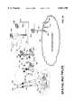
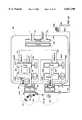
- FIG. 1shows a wireless cellular network incorporating spatial multiplexing and multiple access according to the current invention.
- FIG. 1Bis a detailed view of selected cells within the cellular network shown in FIG. 1A.
- FIG. 1Cshows a cell architecture that provides overlapping regions suitable for multi-base spatial multiplexing.
- FIGS. 2A-Fshow alternate embodiments for the subscriber units utilized in the wireless cellular network shown in FIGS. 1A-B.
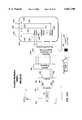
- FIG. 3shows a detailed hardware block diagram of a single base station and subscriber unit for use in the wireless cellular network shown in FIGS. 1A-B.
- FIGS. 4A-Jshow detailed hardware block diagrams of the multiple access hardware for controlling the transmission of subscriber datastream(s) from one or more of the base stations within the wireless network.
- FIGS. 5A-Bshow detailed hardware block diagrams of the hardware associated with the receipt of multiple subscriber datastream(s) at the base stations of the wireless network of the current invention.
- FIG. 6shows a detailed view of the signals and the symbols associated with the transmission and receipt of spatially multiplexed signals according to an embodiment of the current invention.
- FIGS. 7A-Bshow detailed hardware block diagrams of the configurable spatial processor associated with the receiver circuitry receiver, according to an embodiment of the current invention.
- FIGS. 7A-Dshow detailed hardware block diagrams of a configurable space and space-time processor associated with the configurable spatial receiver according to an embodiment of the current invention.
- FIG. 8shows in-band training and data signals for calibrating the spatially configurable receiver during the transmission of spatially multiplexed data, according to an embodiment of the current invention.
- FIGS. 9A-Bare respectively detailed hardware block diagrams of a spatially multiplexed transmitter and receiver implementing a time-division multiple access protocol (TDMA), according to an embodiment of the current invention.
- TDMAtime-division multiple access protocol
- FIGS. 10A-Bare respectively detailed hardware block diagrams of a spatially multiplexed transmitter and receiver implementing a frequency-division multiple access protocol (FDMA), according to an embodiment of the current invention.
- FDMAfrequency-division multiple access protocol
- FIGS. 11A-Bare respectively detailed hardware block diagrams of a spatially multiplexed transmitter and receiver implementing a code-division multiple access protocol (CDMA), according to an embodiment of the current invention.
- CDMAcode-division multiple access protocol
- FIGS. 12A-Bare respectively detailed hardware block diagrams of a spatially multiplexed transmitter and receiver implementing a space-division multiple access protocol (SDMA), according to an embodiment of the current invention.
- SDMAspace-division multiple access protocol
- FIGS. 13A-Bare process flow diagrams showing the acts associated with respectively the spatially multiplexed transmission and reception of datastream(s) in any one of a number of multiple access protocols, according to an embodiment of the invention.
- a method and apparatuswhich allows for both spatial multiplexed and non-spatial wireless communications between portable units and corresponding selected ones among a plurality of base stations.
- the methods and apparatus of the current inventionmay be implemented on a dedicated wireless infrastructure or may be superimposed on existing wireless communications systems, such as cellular telephone and paging services, which are currently in place around the world.
- the methods and apparatusinclude implementation in any of a number of multiple access protocols.
- substreamsoccupy the same channel of a multiple access (MA) protocol, the same time slot in a time-division multiple access (TDMA) protocol, the same frequency slot in frequency-division multiple access (FDMA) protocol, the same code/key sequence in code-division multiple access (CDMA) protocol or the same spatial target location in space-division multiple access (SDMA) protocol.
- the substreamsare applied separately to the N transmit antennas and launched into the radio channel. Due to the presence of various scattering objects (buildings, cars, hills, etc.) in the environment, each signal experiences multipath propagation.
- the composite signals resulting from the transmissionare finally captured by an array of receive antennas with random phase and amplitudes. For every substream the set of N received phases and N received amplitudes constitute its spatial signature.
- the spatial signature of each of the N signalsis estimated. Based on this information, a signal processing technique is then applied to separate the signals, recover the original substreams and finally merge the symbols back together.
- Linear or nonlinear receiverscan be used providing a range of performance and complexity trade-offs.
- a linear spatial multiplexing receivercan be viewed as a bank of superposed spatial weighting filters, where every filter aims at extracting one of the multiplexed substreams by spatially nulling the remaining ones. This assumes, of course, that the substreams have different signatures.
- the rate improvement factor allowed by spatial multiplexingis the minimum of these two numbers. Additional antennas on the transmit or receive side are then used for diversity purposes and further improve the link reliability by improving, for example, the signal-to-noise ratio or allowing for smaller fading margins, etc.
- Effectively spatial multiplexingallows a transmitter receiver pair to communicate in parallel through a single MA channel, hence allowing for a possible N-fold improvement of the link speed. More improvement is actually obtained if we take into account the diversity gain offered by the multiple antennas (for instance, in a Raleigh fading channel). Such performance factors are derived ideally under the assumption that the spatial signatures of the substreams are truly independent from each other.
- the level of independence between the signatureswill determine the actual link performance.
- the performanceusually exceeds that obtained by a single antenna at the transmitter and receiver. For example, at two GHz, assuming the base station and the subscriber unit are spaced apart by one mile and using three antennas at each end of the link, a scattering radius of about 30 feet (both ends) is enough to achieve maximum performance.
- FIG. 1Ashows a plurality of subscriber units wirelessly coupled over a cellular network to a network 100.
- Network 100may include: a local area network (LAN), a wide area network (WAN), a public switched telephone network (PSTN), Public Land Mobile Network (PLMN), an adhoc network, a virtual private network, an intranet or the internet.
- the wireless systemincludes: a central office (CO) 102, a master switch center (MSC) 106, a ground based relay station 110, satellites (112), base stations 120, 126 and 132 (BTS) and subscriber units 156, 138, 144, 150 and 162.
- the subscriber unitsmay be mobile, fixed or portable.
- the base stationsmay be fixed or mobile.
- the base stationsmay include: a tower, satellites, balloons, planes, etc.
- the base stationmay be located indoors/outdoors.
- the cellular networkincludes one or more base stations, where each base station includes one or more spatially separate transmitters.
- the central office 102is coupled to the network 100.
- Network 100may be circuit switched (e.g. point-to-point) or packet switched network.
- the central officeis coupled to a master switching center 106.
- the MSCin traditional cellular systems is alternately identified as: a mobile telephone switching office (MTSO) by Bell Labs, an electronic mobile Xchange (EMX) by Motorola, an AEX by Ericcson, NEAX by NEC, a switching mobile center (SMC) and a master mobile center (MMC) by Novatel.
- the MSCis coupled via data/control line 108 to the satellites via relay station 110 and to the base stations.
- base station controllersBSC may serve as intermediary coupling points between the MSC and the base stations.
- each of the BTSincludes an array of spatially separate antennas for transmission and/or reception.
- the BTSmay also include traditional antenna for whichever of the receive/transmit side of its communication capability lacks spatially separate antenna and associated circuitry.
- Antennas of a transmitter/receiverare defined to be spatially separate if they are capable of transmitting/receiving spatially separate signals.
- Physically separate antennamay be used to transmit/receive spatially separate signals.
- a single antennamay be used to transmit/receive spatially separate signals provided it includes the ability to transmit/receive orthogonal radiation patterns.
- the phrase "spatially separate"shall be understood to include any antenna or transmitter or receiver capable of communicating spatially separate signals.
- the base stationsare configured to communicate with subscriber units of a traditional type, i.e. those lacking either spatially separate transmission/reception as well as spatially enabled subscriber units, i.e. those including either or both spatially separate reception and transmission capabilities.
- distinct subscriber datastream(s) 170, 176 and 182are received by CO 102.
- the COperforms the initial routing of the data streams to the appropriate one of a plurality of MSCs which may be located across the country.
- the MSCperforms several functions. It controls the switching between the PSTN or network 100 and the BTSs for all wireline-to-subscriber, subscriber-to-wireline and subscriber-to-subscriber calls. It processes/logic data received from BTSs concerning subscriber unit status, diagnostic data and bill compiling information.
- the MSCcommunicates with the base stations and/or satellites with a datalink using the X.25 protocol or IP protocol.
- the MSCalso implements a portion of the spatial multiplexing and multiple access processes/logic (SM -- MA) 104B of the current invention.
- Each BTSoperates under the direction of the MSC.
- the BTS and satellites 112manage the channels at the site, supervise calls, turn the transmitter/receiver on/off, inject data onto the control and user channels and perform diagnostic tests on the cell-site equipment.
- Each BTS and satellitealso implement a portion of the SM -- MA processes/logic 104C.
- the subscriber unitsmay be both traditional and spatially enabled and may still communicate over the system. Those subscriber units that are spatially enabled on either/both the transmit/receive side of communications implement SM -- MA processes/logic 104D as well.
- the SM -- MA processes/logicallow high bit rate communications with any of the SM -- MA enabled subscriber units within existing bandwidth constraints and within any of the multiple access (MA) protocols common to wireless communications or combinations thereof.
- MA protocolsinclude: time-division multiple access (TDMA), frequency-division multiple access (FDMA), code-division multiple access (CDMA), space-division multiple access (SDMA) and many other multiple access protocols known to those skilled in the art.
- the SM -- MA processes/logicinclude the ability to selectively allocate spatially separate downlink or uplink capability to any spatially enabled subscriber within a multiple access environment. This capability allows, as to that subscriber, the elevation of bit rates well above those currently available. Thus, a whole new range of subscribers can be anticipated to take advantage of this capability.
- the SM -- MA processes/logicinvolve splitting subscriber datastream(s) destined for spatial multiplexing into substreams and intelligently routing and re-routing the substreams during a call session so as to maintain consistent quality of service (QoS).
- QoSquality of service
- the substreamsare communicated on the same channel using the same access protocol, thus not requiring additional resources or bandwidth to implement.
- the processes/logicinclude: access protocol assignment, channel assignment, monitoring of spatial separation, determination/re-determination of spatial signatures for each communication link, routing/re-routing between single-BTS and multi-BTS, handoff and control of substream parsing/combining.
- datastream(s) 170, 176 and 182are shown originating on network 100.
- the SM -- MA processes/logic 104have parsed and routed subscriber data stream 170 into substreams 172-174, which are transmitted on a single channel of a multiple access protocol over the spatially separate antenna 134-136 of BTS 132.
- Subscriber unit 138via spatially separate antenna 140-142, receives composite signals 172-174 resulting from the substream transmission and utilizing SM -- MA processes/logic 104D, derives the substream and original datastream 170 therefrom.
- the datais delivered to the computer 190 to which the fixed subscriber desktop unit 138 is coupled.
- the cellular environmentmay also be implemented utilizing aerial equivalents of the base stations.
- a plurality of satellites 112generally deliver subscriber datastream(s) via spatially separate antennae on each of the satellites to a cellular network, i.e. 114.
- a call over a cellular networkmay require using two channels simultaneously; one called the user channel and one called the control channel.
- the BTS(s)transmit and receive on what is called a forward/downlink control channel and the forward/downlink voice/data channel and the subscriber unit transmit/receive on the reverse/uplink control and voice/data channels.
- Completing a call within a cellular radio systemis quite similar to the PSTN.
- a subscriber unitWhen a subscriber unit is first turned on, it performs a series of startup procedures and then samples the received signal strength on all user channels. The unit automatically tunes to the channel with the strongest receive signal strength and synchronizes to the control data transmitted by the BTS(s).
- the subscriber unitinterprets the data and continues monitoring the controlled channels.
- the subscriber unitautomatically re-scans periodically to ensure that it is using the best control channel.
- callscan take place between a wireline party and a subscriber unit or between two subscriber units.
- the MSCreceives a call from either a wireline party or in the form of a call setup packet from the network 100.
- the MSCdetermines whether the subscriber unit to which the call is destined is on/off hook. If the subscriber unit is available, the MSC directs the appropriate BTS to page the subscriber unit.
- the subscriber unitresponds to the BTS indicating its availability and spatial multiplexing capabilities, receive and/or transmit.
- the MSC/BTS switchassigns an idle channel, configures spatial processing capability on both the subscriber unit and BTS(s) if appropriate, and instructs the subscriber unit to tune to that channel.
- the subscriber unitsends a verification of channel tuning to the BTS(s) and then sends an audible call progress tone to the subscriber I/O unit causing it to ring.
- the switchterminates the call progress tone when it receives positive indication the subscriber has answered and the conversation or communication has begun.
- Calls between two subscriber unitsare also possible in the cellular radio system.
- the calling partyenters the called number into the unit's memory via the touch pad and then presses the send key.
- the MSCreceives the caller's identification number and the called number then determines if the called unit is free to receive the call.
- the MSC switchsends a page command to all base stations and the called party, who may be anywhere in the service area, receives the page.
- the MSCdetermines the spatial multiplexing capability of both subscribers. Following a positive page from the called party, the switch assigns each party an idle user channel and instructs each party to tune into that respective channel. Then the called party's phone rings. When the system receives notice the called party has answered the phone, the switch terminates the call progress tone and a communication can begin between two subscriber units. If spatial multiplexing is enabled, the communication link will include that capability.
- One of the most important features of the cellular systemis its ability to transfer calls that are already in progress from one cell site/base station to another as a subscriber unit moves from cell to cell or coverage area to coverage area within the cellular network. This transfer process is called a handoff.
- Computers at the BTStransfer calls from cell to cell with minimal disruption and no degradation in quality of transmission.
- the handoff decision algorithmis based on variations in signal strength.
- the MSCmonitors the received signal strength of each user channel. If the signal level on an occupied channel drops below a predetermined threshold for more than a given time interval, the switch performs a handoff provided there is a vacant channel.
- a traditional handoffinvolves switching the transmission point of a subscriber session (datastream) from one BTS to another.
- various types of handoffe.g. partial and full may take place.
- the handoff operationmay involve the MSC re-routing the call and the entire datastream or selected substreams thereof to different antennas of the same BTS or to a new BTS/BTSs in whole or in part.
- the re-routingis partial, at least one substream communication path is left unchanged while other of the substreams are re-routed to antennas on another BTSs.
- the handoffis full the multiple substreams transmitted from one or more BTSs are re-routed to other BTS(s).
- call setupmay be implemented using protocols including: ALOHA, slotted-ALOHA, carrier sense multiple access (CSMA), TDMA, FDMA, CDMA, SDMA, etc., or any combination thereof.
- protocolsincluding: ALOHA, slotted-ALOHA, carrier sense multiple access (CSMA), TDMA, FDMA, CDMA, SDMA, etc., or any combination thereof.
- each BTS 132in the embodiment shown, includes spatially separate antenna array. There may be any number of antennas. In some spatial environments, baud rates for spatially multiplexed communications on a single channel will increase linearly with the number of antennas allocated by subscriber unit and BTSs to a call session.
- each BTSs arrayincludes at least two antennas 134 and 136.
- the BTSmay include either or both spatial multiplexing capability on the downlink (transmit) or uplink (receive) side. In the embodiment shown, each BTS includes spatial multiplexing capability on both the downlink and uplink.
- each of the following embodimentsutilizes two antennas to implement SM, any number of antennas on a single BTS or multiple BTSs may be utilized without departing from the scope of the invention.
- FIG. 1Bshows a more detailed view of the BTS and subscriber units shown in FIG. 1A.
- Each BTSincludes two spatially separate antennas.
- BTS 120includes antennas 122-124.
- BTS 126includes antennas 128-130.
- BTS 132includes antennas 134-136.
- many of the subscriber unitsalso include at least two spatially separate antennas.
- Subscriber unit 150includes spatially separate antennas 152-154.
- the MSChandles the routing of subscriber datastream(s) 170, 176 and 182 from network 100 to the appropriate BTSs for transmission to the appropriate subscriber unit.
- the SM -- MA processes/logicinclude the ability to determine whether to implement or not implement spatial multiplexing (SM), based on either the presence/absence of SM capabilities in the corresponding subscriber unit and/or on the nature of the datastream. If, for example, the subscriber lacks SM capability on either or both the uplink/downlink, then the corresponding datastream will not be parsed into substreams. Alternately, even if the subscriber unit and BTS have SM capability on both downlink and uplink, certain types of datastream(s) may not require SM processing. Examples of these might include: traditional voice call sessions, call sessions which require only low QoS or datastream(s) which require only very low bit rates or are susceptible to buffering and delayed transmission.
- SMspatial multiplexing
- datastream 182is traditional mode traffic, e.g. a subscriber telephone call between an upstream subscriber and the subscriber unit 144.
- Subscriber unit 144is located within a cell serviced by BTS 132. Under the control of MSC 106, the datastream 182 is transmitted over signal line 108 directly to the corresponding base station 132 without being split or parsed into associated substreams.
- datastream(s)182is transmitted from a single antenna, e.g. antenna 134, without any SM techniques. That transmission is received by the subscriber unit 144.
- subscriber unit 144may be a traditional cell phone lacking SM capability. Alternately, subscriber unit 144 may be SM enabled but, nevertheless, receives the call in traditional mode after appropriately configuring itself to opt out of SM receive side processes/logic, electing instead traditional mode.
- datastream(s) 170is handled using SM -- MA processes/logic 104 -- .
- the datastream 170 and/or substreams thereof, depending on the embodiment,is routed by the MSC to BTS 132.
- the processes/logic 104provide to each antenna 134-136 of BTS 132 a single substream derived from the original datastream 170, on a common channel within the appropriate access protocol.
- Those substreamsare received as composite signals by the spatially separate antenna 140-142 (see FIG. 2B) of subscriber unit 138.
- the subscriber unit 138utilizing SM-MA processes/logic 104D, derives the substreams from the composite signals and combines these into the initially transmitted datastream(s) 170.
- Datastream(s) 176is also subject to SM -- MA processes/logic 104 -- .
- the datastream 176 and/or substreams thereof, depending on the embodiment,is routed by the MSC, initially to BTS 132 for single-base transmission to subscriber unit 150.
- SM-MA processes/logic implemented collectively at the MSC 106 and BTS 132result in the splitting/parsing of the datastream(s) 176 into substreams 178-180. Initially those substreams are received as composite signals by the spatially separate antenna 152-154 (see FIG. 2C) of subscriber unit 150.
- the subscriber unit 150utilizing SM -- MA processes/logic 104D, derives the substreams from the composite signals and combines these into the initially transmitted datastream(s) 176.
- SM or SM -- MA communications between the BTS and the associated subscriber unitmay be either line-of-site (LOS) or multipath.
- Multipath communicationsare likely in environments, such as a city, where buildings and other objects deflect signals transmitted from the BTS many times before their arrival at the subscriber unit.
- LOSline-of-site
- Multipath communicationsare likely in environments, such as a city, where buildings and other objects deflect signals transmitted from the BTS many times before their arrival at the subscriber unit.
- transmissions originating from spatially separate antennas of a single BTSmay arrive at a subscriber unit along signal paths which cannot be spatially separated by the antenna array on the subscriber unit.
- the substreams 180 and 178 -- Sare transmitted initially from a single BTS 132.
- a spatial reconfigurationis initiated by the spatial multiplexing processes/logic 104.
- the determinationmight, for example, result from the subscriber unit signaling the BTS or from the BTS determining that the bit error rate (BER) of the transmission exceeded an acceptable level.
- BERbit error rate
- the signaling from the subscriber to the base station(s) for a change of a spatial transmission configurationis simplified.
- the BTSmay, by analyzing the received signals, determine that they can not be adequately separated and in response, alter the spatial configuration of the transmissions to the subscriber unit with which it shares a channel. In the example shown, this reconfiguration results in a change of spatial configuration to multi-base transmission.
- Substream 178 -- Mis re-routed through BTS 120 and specifically antenna 122. Because subscriber unit 150 is positioned in an area in which the transmissions from BTS 120 and 132 overlap, the change in spatial configuration is possible. The increased spatial separation on the transmit side increases likelihood that the substreams can be spatially separated by the subscriber unit 150 and its associated SM-MA processes/logic 104D.
- FIG. 1Cshows another embodiment of the current invention in which a cell architecture which provides overlapping regions suitable for multi-base spatial multiplexing is shown.
- BTSs 186A-Cform an overlapping region between them in which they are shown in spatially multiplexed communication with subscriber unit 138.
- BTSs 186C-Eform an overlapping region between them, in which they are shown in spatially multiplexed communication with subscriber unit 150A.
- BTSs 186C, F-Galso form an overlapping region between them, in which they are shown in spatially multiplexed communication with subscriber unit 150B.
- the communications with subscriber units 138, 150A-Bare conducted on separate channels to avoid co-channel interference. Diversity techniques can be simultaneously implemented. More distant cells may re-use the same channels provided co-channel interference is tolerable.
- FIGS. 2A-Fshow alternate embodiments of subscriber units which may be either fixed, portable or mobile.
- FIG. 2Ashows a mobile cellular phone 144 with a single antenna 146.
- the single antennaincludes the capability of transmitting and/or receiving spatially separable signals utilizing orthogonal di-poles.
- subscriber unit 144is a traditional cellular phone which does not have the capability of transmitting/receiving a spatially separable signal.
- Either embodimentmay be compatible with the system shown in FIGS. 1A-B, provided that system includes an embodiment of the invention with the ability to detect the transceiver capabilities of the subscriber units and to configure communications between that unit and the corresponding BTS accordingly.
- FIG. 2Bshows a fixed subscriber unit 138 coupled to a computer 190.
- high-speed data communications between computer 190 and a wireless communication network with spatial multiplexing capabilitiesis enabled by fixed subscriber unit 138.
- Fixed subscriber unit 138is shown with an antenna array including antennas 140-142.
- additional antennasare provided. These may be utilized either for spatial multiplexing or to implement receive/transmit processing, e.g. diversity techniques, beam forming, interference cancellation, etc., the latter for the purpose of improving communication quality and link budget.
- receive/transmit processinge.g. diversity techniques, beam forming, interference cancellation, etc.
- the current state of the artrequires a minimum separation between antennas 140-142, i.e. D1 equivalent to 1/2 the carrier wavelength. Further improvements in signal processing may avoid this requirement.
- FIG. 2Cshows a mobile subscriber unit, i.e. a cellular telephone 150, reconfigured for implementation of SM or SM -- MA on either or both of the transmit (uplink) or receive (downlink) side of its communication with the BTSs.
- the antennas 152-154are provided.
- FIG. 2Dshows a personal digital assistant (PDA) 200 and associated docking station 202 configured to implement SM or SM -- MA communications on either or both the transmit and receive portions of its communications.
- PDApersonal digital assistant
- the antenna arraywhich in the embodiment shown, includes two antennas 204-206 is provided.
- An example of personal digital assistants currently on the market that could be configured to utilize the current inventionis the Palm Pilot xxTM product sold by 3Com Corporation.
- FIG. 2Eshows a mobile subscriber unit 210 implemented as part of an automobile 216.
- the antenna array associated with this unitis not shown.
- the use of SM or SM -- MA wireless communications between vehicles and base stationscan provide such benefits as vehicle navigation, routing, and diagnostics.
- FIG. 2Fshows a notebook computer 220 configured for SM or SM -- MA communication utilizing an antenna array with antennas 222-224 and associated hardware and processes/logic.
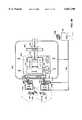
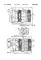
- FIG. 3is a detailed hardware block diagram of a subscriber unit 138 and a BTS 132.
- the BTS 132includes: a multiple access spatial transmitter 310, a multiple access spatial receiver 330, a controller module 320 and upstream processes/logic 300, further details of which are provided in the accompanying FIGS. 4-5.
- the subscriber unit 138includes: a multiple access spatially configured receiver 380, a multiple access spatially configured transmitter 350 and a control unit 370.
- the multiple access spatial transmitter 310includes: a selector 312, a final transmission stage 316 and optionally may include transmit processes/logic 314.
- the final stage transmitter 316is coupled to a spatially separate antenna array which includes antennas 134T-136T.
- the subscriber datastream(s) and/or substreams thereofare provided to the selector 312 from the upstream processes/logic 300.
- the selectorUtilizing either in band or out of band control signals embodied in the datastream(s)/substreams themselves or separately communicated from the SM -- MA processes/logic at the MSC 106 or elsewhere, the selector implements the MA protocol utilized by the wireless network. That protocol, as discussed above, may include: TDMA, FDMA, CDMA or SDMA, for example.
- the selectorplaces each of the datastream(s)/substreams on the appropriate channel.
- Each of the datastream(s)/substreamsare then passed through the optional transmit processes/logic, in which any of a number of well-known prior art signal processing techniques may be implemented to improve the quality of transmission. These techniques include, but are not limited to, diversity processing, space-time coding, and beam forming.
- the datastream(s)/substreamsare then passed to the final transmit stage 316.
- Traditional mode trafficmay be routed by the SM -- MA processes/logic 104 -- to the appropriate antenna 134T-136T for transmission. If diversity processing is implemented, even traditional mode traffic may be transmitted using multiple antennas. Spatial mode traffic, i.e. the individual substreams thereof, will be routed to the appropriate one of the two antennas 134T-136T.
- the subscriber unit SM -- MA configurable receiver 380includes: receiver first stage 382, optional receive processes/logic 384, spatial/space-time processor 386, decoder 388, combiner 390 and I/O module 392.
- the receiver first stageis coupled to a spatially separate antenna array, e.g. antennas 140R-142R.
- the SM -- MA configurable receiver 380 of the subscriber unit 138may be configured for spatial/traditional mode signal reception on the requisite channel within the multiple access protocol.
- the antenna arraye.g.
- antennas 140R-142Rdetect downlink composite signals derived from the spatially separate transmission of the substreams through antennas 134T-136T. These composite signals are down converted, demodulated and sampled by the receiver first stage 382. The composite signals are then passed to the receive processing module 384 and may be subject to receive side processing if implemented. From the receive processing module, the composite signals are passed to the spatial processor 386.
- the spatial/space-time processor via in/out band control signalsis also configured to derive the appropriate number of substreams, i.e. equivalent to the number transmitted, from the BTS(s). Utilizing logic associated with space/space-time processing (see FIGS.
- that processorin conjunction with decoder 388, generates estimated source substreams which are passed to the combiner 390.
- the combiner 390via in/out band control signals is also configured to combine the substreams into an estimated subscriber datastream(s) corresponding to that transmitted from the BTS 132.
- the datastream(s)are passed to the I/O module for presentment/delivery as, e.g., audio, image or data.
- the uplinkmay, in an embodiment of the invention, not include SM capability, leaving that capability to the downlink alone. This asymmetric capability may be implemented on either the downlink or the uplink without departing from the scope of this invention.
- the uplink from the subscriber unit 138 to the BTS 132may use the same or different hardware/firmware/processes/logic to that utilized for the downlink.
- the uplinkis traditional with no SM -- MA capability.
- the uplinkincludes both SM and MA processes/logic.
- the datastream(s) received by the I/O module 352are passed to parser 354.
- the parseris configurable to generate a traditional datastream or a variable number of substreams thereof.
- the parserparses all datastream(s) into a fixed number of substreams. Where there are no SM uplink capabilities there is no parser.
- the configurable parseralso includes a mode detector to determine whether the datastream(s) should be split into substreams. That determination, as discussed above, may be based on any number of criteria including, but not limited to, traditional vs. spatial mode, QoS, bit rate requirement, feasibility, etc.
- the mode detectordetermines that spatial mode transmission of the datastream is appropriate
- the parserwill split the datastream(s) into a plurality of substreams, the number of which may itself be configurable. These substreams are then passed to the selector 356.
- the selectorresponsive to in/out of band control signals implements the appropriate access protocol, including the placement of the datastream(s) and/or substreams onto the appropriate channel within that protocol.
- the datastream(s) and/or substreams thereofare then optionally passed to transmit processes/logic 358, which may implement any number of well-known prior art signal processing techniques, including the above discussed diversity methodology, to improve signal reception.
- the substreams and/or datastream(s)are then passed to the final transmit stage 360 where they are encoded, modulated, and up-converted for transmission on a single channel through spatially separate transmit antennas 140T-142T.
- Composite signals corresponding theretoare received by antennas 134R-136R of the SM -- MA configurable receiver 330 of the BTS.
- the receiver 330is SM -- MA configurable.
- the receiver 330includes a first stage receiver 332, mobility detector 334, receive processes/logic 336, spatial/space-time processor 338 and a decoder 340.
- the composite signalsare passed by antennas 134R-136R to the first stage receiver. This is configurable to receive the communications on the appropriate channel within the MA protocol as determined by SM -- MA processes/logic 104 -- . These composite signals are down-converted/demodulated and sampled.
- the mobility detector 334monitors the composite signals for Doppler shift/spread.
- Doppler shift/spread of the composite signalscorrelates with the mobility or lack thereof of the subscriber unit.
- the absence of a Doppler shift/spreadindicates that the subscriber unit is fixed.
- This determination on the part of the mobility detectormay be used to initiate one or more of the following processes/logic: spatial reconfiguration, training/retraining of the spatial/space-time processors and/or handoff.
- training/retrainingmay include varying the training interval or duration or selection of a different training sequence.
- the composite signalsare then passed to the optional receiver processes/logic 336.
- These processes/logic, as described above,may include any of a number of well-known techniques including diversity processing.
- the composite signalsare then passed to the configurable space/space-time processor 338.
- the space/space-time processorUtilizing in/out of band control signals from the MSC and/or the subscriber unit, the space/space-time processor configures itself to generate a number of substreams or a single datastream(s) equivalent to those transmitted from the corresponding subscriber unit.
- These estimated subscriber substreams/datastream(s)are then passed to the decoder 340.
- the decoderdecodes the symbols to their corresponding binary equivalent.
- the datastream(s) and/or substreamsare then passed to upstream processes/logic 300.
- Both the subscriber unit 138 and the BTS 132are shown to include respectively control modules 370 and 320. These control modules implement a subset of the control processes/logic 104 required to implement the SM -- MA processes, such as training of the space/space-time processors 338 and 386, etc.
- Trainingrefers to the requirement that, in order to implement a space/space-time processing on the receive side of whichever link down/up is implementing SM, it is necessary that the space/space-time processor be equipped with an appropriate model of the spatial characteristics of the environment in which the signals will be passed between the subscriber unit and the associated BTS(s).
- Different types of training methodologymay be appropriate, depending on whether the subscriber units are fixed/mobile, and if mobile, depending on the speed at which they are moving. Where a subscriber unit is fixed, training may be accomplished on installation of the unit, at setup of a call or during a call session. Where a subscriber unit is mobile, training/retraining must take place continuously or intermittently. Training for a fixed subscriber unit may take place intermittently as well, although generally at a lower frequency than that associated with a mobile subscriber unit.
- Trainingis generally categorized as blind or non-blind. Training is non-blind when it is incorporated intermittently/continuously using in/out of band training signals, e.g. known sequences such as Walsh codes, transmitted between subscriber unit and BTS(s). Training is blind when it takes place without such signals, relying instead on non-Gaussianity, CM, FA, cyclostationarity or the spatial structure, such as the array manifold. The performance of blind methods will, of course, be sensitive to the validity of structural properties assumed. An excellent reference on the subject, which is incorporated herein by reference as if fully set forth herein, is found in: "Space-Time Processing for Wireless Communications", Arogyaswami J.
- Control module 320includes: processor 324, clock 326, training module 328 and memory 322 for the storage of weights/parameters for the space/space-time processor 338.
- Control module 370 in the subscriber unit 138includes: processor 374, clock 376, training module 378 and memory 372 for the storage of weights/parameters for the space/space-time processor 386.
- the CPUimplements the training portion of the control processes/logic 104. In alternate embodiments of the invention, the CPU may be utilized to implement other of the control processes/logic. In still other embodiments of the invention, the training portion of the control processes/logic is handled upstream at such locations as the MSC or the CO.
- the mobility detector 334signals the CPU 324 when a subscriber unit exhibits minimal Doppler shift/spread, e.g. is fixed.
- the CPU 324directs the transmit module 310 to signal subscriber unit 138 at call setup, or at the start of a call session, to use stored parameters from an earlier training session or to process a setup training session transmitted by the BTS.
- the CPUmay reduce the frequency or duration of a training sequence responsive to a determination that the Doppler shift/spread is minimal.
- the training module 328inserts a known training sequence, e.g. Walsh code, into the downlink transmissions and these are processed by the CPU 374 of the subscriber unit and weights derived therefrom which allow the space/space-time processor 386 to separate the training sequence spatially broadcast from the antenna array of the BTS(s).
- the subscriber unit training module 378inserts a known training sequence into the uplink transmissions as well. These are in turn processed by the CPU 324 and appropriate weights derived therefrom stored in the spatial processor 338 for use with the uplink communications during the call/data-transfer session. Whenever training/re-training takes place, weights are recalculated and stored for use in subsequent SM communications.
- an alternate non-blind training methodologymay be implemented.
- that methodology shown in FIG. 8involves inserting into in/out of band downlink communications the known training sequence. This allows updating of the spatial parameters/weights by the corresponding subscriber unit and its space/space-time processor. This capability allows spatial multiplexing to be implemented in both a mobile and a fixed environment.
- the duration/frequency at which the training intervals are inserted into the up/down link communicationsmay be varied depending on the mobility of the subscriber unit.
- blind training methodsmay be implemented. These unsupervised methods do not need training signals because they exploit the inherent structure of the communication signals.
- the processes/logic 104 and the associated modules/blocks discussed above and in the following disclosuremay be implemented in hardware, software, firmware or combinations thereof without departing from the teachings of this invention. They may be implemented on a single chip, such as a digital signal processor (DSP), or application specific integrated circuits (ASIC).
- DSPdigital signal processor
- ASICapplication specific integrated circuits
- the SM -- MA processes/logic 104may physically reside in any one or all upstream units.
- the processes/logicmay be implemented using master-slave control relationship between CO/MSC and BTS or peer-to-peer control relationship between BTSs alone, or distributed control between CO/MSC and BTS.
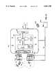
- FIGS. 4A-Fshow an embodiment of the BTS/MSC/CO side of the processes/logic 104 -- for implementing SM -- MA.
- FIGS. 4A-B and 4D-Eshow a partial handoff.
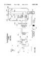
- FIG. 4Ashows BTSs 120 and 132 coupled to MSC 106 and to the associated upstream processes/logic 300 of processes/logic 104 -- .
- the BTS 120is shown with the associated final transmission stage 316B and the selector 312B.
- the BTS 132is shown coupled to the final transmission stage 316A and to the selector 312A.
- the upstream processes/logic 300include a detector 400, parser unit 402 and router 420.
- the parser unit 402includes a parser module 404 and clock 406 as well as a stretcher 408 and its clock 410.
- the MSC 106is shown coupled via its data/control line 108 to each of the above-discussed modules.
- each of the above-discussed hardware and software modulesrepresents a master/slave embodiment of the current invention.
- peer-to-peer control methodologymay be utilized instead.
- distributed control methodologymay be implemented, e.g. each of the above-discussed modules may contain additional intelligence, sufficient to signal downstream/upstream modules as to the appropriate configuration to adopt, responsive to the datastream(s)/substreams being processed, the channel and access methodology to be utilized.
- Datastream(s) 176is delivered to mode detector 400.
- a mode detectionis utilized.
- this moduleprovides the capability of distinguishing datastream(s).
- Datastream(s)might, as discussed, be categorized as traditional vs. spatial, or on the basis of QoS or bit rate requirement.
- the detector 400determines that the datastream(s) 176 is destined for spatial mode processing. Responsive to that determination, the parser 404 is configured to parse the datastream(s) 176 into a plurality of the substreams. In the example shown, the two substreams 450-452 are generated by the parser. The substreams each contain a portion of the actual data from the original datastream(s).
- the function of the stretcher 408, to which the substreams are passed,is to effectively lower the baud rate at which the substreams are transmitted.
- clocks 406 and 410which are coupled to respectively the parser and the stretcher.
- Clock 410operates at a rate which is a fraction of the rate of clock 406. The specific fraction is determined by the number of substreams generated by the parser 404. For example, if parser 404 generates from a single datastream(s) two substreams, then each of the substreams will be transmitted at a baud rate which is effectively 1/2 that of the original datastream(s). The stretched substreams are then passed to the router 420.
- the substreamsneed not be stretched, rather buffered and transmitted at the same baud rate in bursts, if the channel will support the resultant communication rate.
- the routeroperating, in the embodiment shown, under the control of the MSC 106 sends the selected substreams 454 and 456 to a single BTS 132 for single-base spatial transmission from each of the spatially separate antenna of that BTS.
- Those substreams passed through the selector 312are injected on an appropriate channel within the multiple access protocol.
- the channel determinationis made by the SM -- MA processes/logic 104 that portion of which may be localized in a master/slave control implementation at the MSC.
- the substreamsare then passed to the final transmission stage 316A for transmission to the subscriber unit 150 (see FIG. 6).
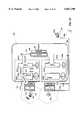
- FIG. 4Bshows hardware/software modules identical to those discussed above in connection with FIG. 4A.
- the router 420responsive to a signal from, for example, the MSC 106 has re-routed one of the substreams to BTS 120. That substream 454 is passed to the selector 312B associated with BTS 120. The corresponding substream 456 is presented to selector 312A associated with BTS 132. Under the control of the MSC, each selector is directed to place the substreams on the same MA channel on each of the base stations.
- the final transmission stages 316A-B of each BTSplaces the substreams on one antenna of its spatially separate antenna array for transmission to the subscriber 150.
- the subscriber 150is in a location in which the signals from base stations 120 and 132 overlap.
- the composite signals 180 and 178 -- M resulting from the transmission of spatially distinct subscriber substreamsare received with spatially separable signatures by the subscriber unit 150 which, as discussed above, is equipped with spatially separate antennas.
- the determination to move from a single-base spatial transmission (see FIG. 4A) to multi-base spatial transmission, as shown in FIG. 4B,may be made as a result of any one of the number of distinct determination methods.
- an evaluator portion of either the space/space-time processor 386 or the decoder 388 of the subscriber unit 138determines that an incoming composite signal cannot be spatially separated into the required number of substreams.
- the subscriber unitsignals the BTS that a change of spatial configuration is required. This signal is processed by the BTS and may be passed to the MSC 106.
- the MSCdirects the router and selected BTSs, e.g.
- BTSs 120 and 132to prepare for and transmit the substreams on an assigned channel.
- This transition from single-base to multi-base spatial transmissionis handled transparently to the subscriber, in order to maintain a consistent QoS throughout the transmission by increasing the spatial separation of the transmitted substreams.
- FIG. 4Cshows an alternate embodiment of the invention that includes the capability of mode detecting between, for example, traditional and spatial mode datastreams.
- Datastream(s) 182is presented to detector 400 via data/control line 108.
- the datastream(s)might, for example, be a traditional subscriber telephone call or a datastream which has both a low bit rate and QoS requirement.
- the parser unit 402may be configurable, so as not to subject all incoming datastream(s) to parsing or, if parsed, so as not to parse into a fixed number of substreams. In the embodiment shown, such capability is implemented.
- the detectordetermines that the datastream is traditional mode.
- the datastream(s) 182is passed unparsed to the router 420.
- the router 420passes the datastream(s) 182 to the selector 312A of the associated BTS 132.
- the selector and the final transmissions stage 316Ainject the datastream(s) 182 on the appropriate channel of the appropriate multiple access protocol and transmit it via a selected one of the antennas, within the array from which it is received, by subscriber unit 144.
- That subscriber unitmay be a traditional mobile phone lacking any spatial transmission characteristics. Alternately, the subscriber unit may be spatially configurable as well (see FIG. 2A).
- BTS 132injects a control signal to the spatially configurable subscriber unit 144 and, in particular, to the configurable space/space-time processor thereof, indicating that the incoming composite signals are to be treated as a single datastream(s).
- traditional mode datastreamsincluding, for example, traditional voice telephone calls, may be subject to SM.
- each of the above-discussed datastream(s) 178, 176, 182may include multiple subscriber sessions, time-division multiplexed for example. In this case, all the above-mentioned methodology may be practiced successively on each of the subscriber sessions of a single datastream.
- FIG. 4Dshows multiple subscriber datastream(s) presented to the detector 400. Specifically datastream(s) 176 and 182 are shown. The first of these datastream(s) is destined for spatial treatment and the second of these datastream(s) 182 is destined for non-spatial treatment. This determination is made by the mode detector 400 based on criteria including, but not limited to, those discussed above.
- the parsing unit 402is, in this embodiment of the invention, configurable to concurrently handle multiple subscriber sessions. Upon receipt of control information received either directly from the detector 400 or indirectly from the MSC 106, the parsing module 402 performs the following concurrent operations. The traditional mode datastream(s) 182 is left unparsed and passed directly to the router 420.
- the spatial mode datastream(s) 176is parsed by parser 404 into substreams 450-452. These substreams are stretched in stretcher 408, as discussed above, and passed to router 420.
- the router 420operating under the control of the MSC, for example, directs each of the datastream(s) and substreams to a single BTS 132 and specifically the associated selector 312A of that BTS.
- substreams generated by the parserare labeled 450-452.
- the substreams passed by the routerare labeled 454-456.
- This change in reference numberis meant to indicate that the initial parsing operation may be accompanied by a lowering of the bit rate or stretching of the clock on which these substreams are transmitted.
- an alternate methodology for implementing the inventionwould be to maintain the same the bit rate, provided it was compatible with the bandwidth of the wireless channel on which the transmission was to take place, and to buffer the data accordingly for transmission in bursts, along with other similarly processed datastream(s)/substreams.
- the selector 312A and final transmission stage 316A of BTS 132transmit the substreams 454-456 on a common channel and, depending on the access methodology, may transmit the datastream(s) 182 on the same or another channel.
- Signal 182is transmitted from an antenna of BTS 132 to subscriber unit 144.
- the individual substreams and the associated signals 180, 178 -- S of the spatial mode datastream(s) 176are transmitted to the subscriber unit 150.
- FIG. 4Eshows an embodiment of the invention identical to that described and discussed above in connection with FIG. 4D.
- Router 420re-routes one of the substreams 454-456 of the spatially processed datastream(s) 176 to form a multi-base spatial transmission configuration. That determination to re-route, as discussed above, may originate either from signals received from the corresponding one of the subscriber units which is unable to spatially separate the substreams or alternately may result from a determination by the BTS initially implementing single-base transmission that the bit error rate (BER) is unacceptably high.
- subscriber unit 144continues to receive composite datastream(s) 182 from an antenna on BTS 132.
- the composite signals received by subscriber 150now, however, originate from a multi-base configuration.
- the substream 454has been re-routed by router 420 to BTS 120, so the composite signals 180, 178 -- M originate from BTSs 132,120, respectively.
- a single substream in single or multi-base configurationmay be transmitted from more than one antenna, if diversity or beam forming transmit processes are implemented in addition to spatial multiplexing.
- FIGS. 4F-Jshow an alternate embodiment of the invention in which the router, as described and discussed above in connection with FIGS. 4A-E, is positioned upstream of the parsing unit rather than downstream of that unit. Consequently, each of the base stations has associated with it a corresponding parsing unit.
- FIGS. 4F-G and FIGS. 4I-Jshow a partial handoff.
- FIG. 4Fshows MSC 106, BTSs 120 and 132 and the upstream processes/logic 300.
- Each of the base stations 120 and 132includes selectors and final transmission stages.
- the detector 400communicates directly to the router 422.
- the routercommunicates directly with the parsing units 402A-B associated with BTSs 132 and 120, respectively.
- Single-base spatial processing of subscriber datastream(s) 176is shown.
- the subscriber datastream(s) 176is received by the detector 400.
- the detectordetermines that the mode of the datastream(s) is spatial and that information is passed to the router 422.
- the routerroutes the datastream(s) 176 to the appropriate parsing unit 402A.
- the parsing module 404A of that unitparses the datastream(s) into substreams, e.g. substreams 450-452. Those substreams are passed to stretcher 408A which is coupled to selector 312A. The selector places both the stretched substreams 454-456 on the appropriate channel of the selected MA protocol. Those substreams are transmitted by the final transmit stage 316A of the BTS 132. The signals 178 -- S and 180 are transmitted to subscriber unit 150, along with the control information necessary for that subscriber unit to properly process the incoming communication.
- FIG. 4Gshows a multi-base implementation of the configuration described and discussed above in connection with FIG. 4F.
- the detector 400determines that the datastream(s) 454-456 require spatial processing. Additionally, multi-base transmission is determined to be necessary based, for example, on a subscriber unit signal or on the BER detected by a BTS.
- the router 422responsive to that determination, routes the datastream to parsing units 402A-B.
- Each of the parsing modules 404A-Bis presented information, not only that the datastream(s) needs to be parsed, but also which substreams are to be discarded at each parsing unit in order to implement a multi-base spatial transmission.
- those in control instructionsare generated by the MSC 106.
- the parsing module 404Agenerates substream 452.
- the parsing module 404Bgenerates substream 450.
- Collectively, substreams 450-452contain all the information from the original datastream(s) 176 from which they were parsed.
- the selected substreamsare passed to the corresponding stretching modules 408A-B. These stretching modules in turn pass the substreams with a reduced bit rate or in bursts as substreams 456-454 to the corresponding selectors 312A-B of the associated BTSs 132 and 120.
- the substreamsare placed on the same channels of the multiple access protocol implemented by each BTS. These substreams are transmitted by the corresponding final transmissions stages 316A-B.
- Signal 180 corresponding to substream 456is transmitted by at least an antenna on BTS 132 to subscriber unit 150.
- Signal 178 -- M corresponding to substream 454is transmitted by at least an antenna of BTS 120 to subscriber unit 150.
- FIG. 4Hshows an implementation of the current invention in which the detector 400 includes the capability of distinguishing the mode of the datastream(s), e.g. traditional mode and spatial mode.
- the detector 400upon determining that datastream(s) 182 can be processed in traditional mode, passes that information to the router 422.
- the routerpasses the datastream(s) 182 to the appropriate parsing unit 402.
- the parser unit 402A and specifically parser module 404A thereofavoids parsing the datastream(s) and passes it to the corresponding selector 312A associated with BTS 132.
- the channel and antenna on which that datastream(s) is to be transmitted from BTS 132is determined by the processes/logic 104, e.g. at the MSC.
- the associated signal 182is passed from the BTS to the subscriber unit 144.
- FIG. 4Ishows the introduction of multiple subscriber datastream(s), i.e. datastream(s) 176 and 182 into the embodiment described and discussed above in connection with FIGS. 4F-H.
- the detector 400determines that datastream(s) 182 may be processed in the traditional mode while datastream(s) 176 may be processed in the spatial mode.
- both the datastream(s)are routed by router 422 to a single BTS for, respectively, non-spatial and spatial transmission.
- Stretched datastream(s) 454-456 derived from substreams 450-452 of datastream(s) 176are presented to the selector associated with BTS 132.
- Signals 178 -- S and 180are transmitted to subscriber unit 150 on the same channel of the MA protocol implemented by the BTS.
- Traditional mode datastream(s)may be transmitted on the same or another channel.
- FIG. 4Jshows a multi-base spatial transmission of the datastream(s) 176 discussed above in connection with FIG. 4I.
- a change from single to multi-base transmissionis initiated by the processes/logic 104 -- in response to, for example, a degradation in the bit error rate or to signals from subscriber unit 150 which indicate that a change in spatial configuration is required. This might include changing the antenna selection on the array of a single BTS. The selection might involve a reduction/increase in the number of transmitting antennas. Alternately, in the example shown, a partial handoff is implemented. To implement the partial handoff, router 422 routes the datastream(s) 176 to both parsing units 402A-B.
- Control informationindicating which of the substreams generated by the respective parsing unit is to be passed on to the associated BTS, may also be generated. Responsive to that information, the parsing modules 404A-B each generate only one of the substreams which can be generated from the datastream(s) 176. Each selected substream is stretched by the corresponding stretcher and passed to the corresponding BTS. BTS 132 continues to transmit the traditional mode datastream(s) 182 and the signal corresponding thereto to subscriber unit 144. BTS 132 transmits one of the stretched substreams 456 in the form of signal 180 to subscriber unit 150. The other of the substreams 454 is passed to the subscriber unit 150 as signal 178 -- M from the BTS 120.
- the wireless networkmay not support both traditional and spatial transmission together.
- the detectormay not be required, since all datastream(s) will be handled by spatially transmitting them.
- multi-base operationmay not be implemented, allowing only for single-base SM.
- the routingmay be accomplished by a single BTS which uses in/out of band channels to wirelessly relay one or more substreams to other BTSs for re-transmissions on the assigned channel.
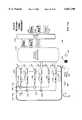
- FIGS. 5A-Bshow the upstream modules associated with the processing of datastream(s) and substreams received by the BTSs. That information may be destined for another subscriber unit or for the network 100 (see FIG. 1A).
- FIG. 5Ashows the base stations 120,132, the upstream processes/logic 300 and the MSC 106.
- single-base SMis implemented.
- the subscriber unit 150is shown transmitting signals 178 -- S and 180. These are received by BTS 132 and processed by the associated modules of its configurable SM receiver 330 (see FIG. 3).
- substreams 454-456are passed to the upstream processes/logic 300.
- the upstream moduleincludes a router 420 and a combiner 500.
- the combiner 500operates in reverse of the manner described and discussed above in connection with the parsing unit 402.
- the router 420passes the substreams 454-456 to the combiner 500.
- the output of the combineris the subscriber datastream(s) 176.
- FIG. 5Bshows the modules discussed above in connection with FIG. 5A during the reception of multi-base spatial transmissions from the subscriber unit 150 as well as the single-base transmission from subscriber unit 144.
- BTS 132 and the associated receiver module 330have their spatial processor configured to generate a single one of the substreams 456 that can be derived from the composite signals 178 -- M and 180 of subscriber unit 150.
- the other substream 454is generated by corresponding modules associated with BTS 120.
- BTS 132 with the receiver 330is configured to generate a single datastream(s) 182 from the composite signal 182 transmitted by the subscriber unit 144.
- the datastream(s) 182 of the associated decoder of that BTS, i.e. decoder 340Ais passed to the router 420.
- the combineris configured to combine substreams 454-456 into datastream 176 and to pass datastream(s) 182 along without combining.
- the method and apparatus of the current inventionmay be used to implement SM -- MA both on the down/up link.
- SMmay be asymmetrically implemented as well, on either the down/up link selectively, without departing from the scope of this invention.
- FIG. 6shows an antenna array of BTS transmitter 132 and the antenna array of the subscriber unit receiver 138 (see FIG. 3).
- the antenna array of the final transmissions stage 316includes antennas 134T-136T.
- the antenna array of the first receiver stage 382includes antennas 140R-142R.
- the first receiver stagepasses the composite signals 640-642 to the space/space-time processor 386.
- the output of the processoris presented to the decoder 388 from which, as output, the substreams 454-456 are generated.
- the transmission of data through a wireless mediummay involve modulation of an information signal derived from a datastream(s) or substream on a carrier signal.
- Informationmay, for example, be contained in the phase and/or amplitude relationship of the signal modulating the carrier.
- Each specific phase and/or amplitude relationship that is utilizedis referred to as a "symbol”.
- the set of all symbolsis referred to as the "constellation”.
- the greater the number of symbols in a constellationthe more binary bits of information may be encoded in each symbol in a given constellation.
- Current communication protocolsallow for constellations with over 1024 symbols, each encoding for one of ten bit combinations.
- Antenna 134Tis shown transmitting a symbol 600 within a signal constellation.
- Antenna 136Tis shown transmitting symbol 606 which corresponds to a different bit sequence derived directly from substream 456.
- the transmission of substream 454 by antenna 134results in at least two signals 602-604.
- the transmission of the symbol 606 by antenna 136generates at least two signals 608-610. Additional signals are likely in a multi-path environment with numerous scattering objects, such as buildings, etc.
- signals 602 and 610 transmitted from respectively antennas 134T-136Tare both received by antenna 140R as a single composite signal.
- the corresponding signals 604 and 608are received by antenna 142R as a single composite signal.
- the spatial processor 386In order for the spatial receiver of the subscriber unit to resolve the composite signals into the estimated subscriber datastream/substreams, the spatial processor 386 must include information about the spatial signatures 620-622 of the transmissions from each of the antennas 134-136. These spatial signatures may be determined using either blind and or non-blind training methods in the manner described and discussed above. By placing the decoder 388 downstream from the space/space-time processor 386, the appropriate symbols may then be derived from the substream and converted into a corresponding binary sequence from which the corresponding portions of the substreams 454-456 may be generated.
- any of a number of other modulation techniquesmay be used to implement the current invention including: continuous phase modulation (CPM), continuous frequency modulation (CFM), phase shift keying (PSK), offset phase shift keying, amplitude shift keying (ASK), pulse position modulation (PPM), pulse width modulation (PWM), etc., without departing from the scope of this invention.
- CPMcontinuous phase modulation
- CFMcontinuous frequency modulation
- PSKphase shift keying
- ASKamplitude shift keying
- PPMpulse position modulation
- PWMpulse width modulation
- FIGS. 7A-Bshow an embodiment of the invention in which the spatial processor 386 is configured for both traditional and spatial mode signal reception. Additionally, in the spatial mode, the spatial processor is configurable to generate a variable number of substreams to correspond to the number transmitted. Spatial processor 386 and the decoder 388 are shown.
- the spatial processor 386includes: first fabric switch 700, first configurable logic 702, second fabric switch 730, second configurable logic 732, an evaluator 740, and a controller 746.
- the spatial processor 386is coupled via the receive processes 384 to the receiver first stage 380 of the subscriber unit, as discussed above in connection with FIG. 3. Similar design applies to the spatial processor 338 in the BTS (see FIG. 3).
- the composite signal(s) detected by the first stage receiveris passed to the fabric switch 700 of the spatial processor. Responsive to signals generated by the control unit 746, the first fabric switch passes the composite signal/signals to one or more of the sub-modules within first logic unit 702.
- a sub-moduleincludes a multiplier 704 and a weight register 712. The multiplier generates an output signal which is a product of the weight stored in weight register 712 multiplied by the incoming composite signal.
- a composite signal 750is presented to fabric switch 700.
- This switchhas been configured utilizing in/out of band control signals to process a single composite signal.
- the output of the multiplieris presented to the second fabric switch 730.
- This fabric switchalso is configurable by means of the control unit 746.
- the fabric switch 730presents the signals from the first logic module in variable configurations to one or more of the summers, e.g. summer 734 which is part of the second configurable logic in this embodiment of the invention. Because a single composite signal is being processed in the embodiment shown in FIG. 7A, only one summer is utilized.
- the input to that summeris the output of the multiplier 704 and the zero input provided by the control unit 746.
- the output of the summer 734is passed to the evaluator 740 (optional).
- the evaluatordetermines when signals that are spatially transmitted are not separable, and if separable, the quality of each link.
- the quality of each linkmay be evaluated using, for example, Signal to Interference Noise Ratio (SINR).
- SINRSignal to Interference Noise Ratio
- the resultant traditional mode datastream(s) 182is passed through the decoder. In the decoder the conversion from symbols to associated bit sequences is implemented. As shown above in FIG. 3, the output of the decoder is passed to an associated combiner.
- the configuration of the configurable spatial processor under the control of control unit 746takes place as a result of in/out of band control signals. These signals may be generated during call setup or during an actual call session by SM -- MA processes/logic 104.
- Composite signals 640-642are presented to the first fabric switch 700. Responsive to signals from the control unit 746, the first fabric switch generates output signals for each of the composite input signals.
- Composite signal 640is passed to a first pair of logic sub-modules within the first logic unit 702.
- Composite signal 642is passed to a second pair of logic sub-modules within the first logic unit 702.
- the first pair of logic sub-modulesinclude: multiplier 704 together with associated weight register 712, and multiplier 706 together with associated weight register 714.
- the second pair of logic sub-modulesinclude: multiplier 708 together with associated weight register 716, and multiplier 710 together with associated weight register 718.
- Multipliers 704-706receive as inputs the composite signal 640.
- Multipliers 708-710receive as inputs the composite signal 642.
- the weight registersmay contain weights obtained during transmission of a training sequence which allow training sequences to be separated. These are multiplied by the corresponding composite signal inputs and the four products are cross-coupled to summers 734-736 of the second logic unit 732 by the second fabric switch.
- the output of summers 734-736is, respectively, the estimated substreams 454-456. In the embodiment shown, these are passed through an evaluator 740 to the decoder 388. Subsequently, the estimated substreams are combined into the original datastream 176 (not shown).
- the decoder 388performs the above-mentioned function of mapping the summer output into symbols and from the symbols, into the appropriate binary sequences.
- the evaluatormay be placed downstream of the decoder and perform a similar function at that location.
- the evaluatormonitors the estimated substreams to determine if they are appropriately separated, and if separable, the quality of the link(s). This determination might, for example, be made during the transmission of a training sequence. When the evaluator determines it is no longer possible to spatially separate the corresponding substreams, that determination may be passed to the upstream processes/logic 104, e.g. the MSC 106 (see FIG. 1). This results in an alteration of the spatial configuration of the transmission.
- a change in spatial transmissionmay be implemented in any number of ways. These include: a change in the antenna selection and/or number at a single base, a change from traditional to spatial mode broadcasting at a single base, a change from single-base to multi-base transmission.
- the evaluatormay pass on the link quality parameters to the upstream processes/logic 104, e.g. the MSC 106. This can help the BTS/MSC/CO side of the processes/logic 104 -- choose the modulation rate (bits per symbol) of each substream, and carry out parsing accordingly.
- FIGS. 7C-Dshow an embodiment of space-time processor.
- the ability to remove the interference in the composite signal caused by the delayed versions of the composite signal over timeis added the ability to remove the interference in the composite signal caused by the delayed versions of the composite signal over time.
- one or more delay elementsmay be introduced into the signal paths in the first logic unit to account for these effects.
- An exploded view of an embodiment of a time logic sub-moduleis shown in FIG. 7D.
- each time sub-moduleis coupled to the output of a corresponding multiplier in the first logic unit.
- Time sub-modules 720-726are coupled to the outputs of multipliers 704-710, respectively.
- Each time modulemay consist of a plurality of delay elements.
- a sub-moduleincludes delay modules 760-762; multipliers 770-772 together with associated weight registers 780-782, as well as a summer 790.
- the output of multiplier 704is an input both to delay module 760 and summer 790.
- the output of delay module 760is an input both to delay module 762 and to multiplier 770.
- the output of delay module 762is an input to multiplier 772.
- the outputs of the multipliersprovide additional inputs to the summer 790.
- the output of the summeris presented to the second fabric switch 730.
- Each time modulemay include additional multipliers with associative delay units and weight registers.
- the space-time processor in FIGS. 7C-Dis configurable.
- FIG. 7Cshows the processor configured for a single input composite signal 750.
- FIG. 7Dshows the space-time processor configured for two composite input signals 640-642.
- the spatial/space-time processor of FIGS. 7A-Dis configurable; e.g. capable of processing a variable number of composite signals and outputting a corresponding number of estimated subscriber substreams.
- the spatial/space-time processoris not configurable; accepting instead a fixed number of substreams and outputting a corresponding fixed number of estimated subscriber substreams.
- any of a number of other processing techniquesmay be used to implement the current invention, including: space-time, space-frequency, space-code, etc.
- thesemay further utilize any, or a combination of techniques including, but not limited to: linear or non-linear processing, Maximum Likelihood (ML) techniques, Iterative decoding/interference canceling, Multi-user detection (MUD) techniques, etc., without departing from the scope of this invention.
- MLMaximum Likelihood
- MODMulti-user detection
- FIG. 8shows a datastream interspersed with the training sequences consistent with a non-blind embodiment of the current invention.
- Training sequences 800-802 and data sequences 850-852are shown.
- Suitable training sequencesinclude orthogonal Walsh codes transmitted by the spatially separate antennas.
- the spatial/space-time processor of the receiverattempts to generate weights which separate the known Walsh code sequences. Those weights are then used in processing the subsequent datastream(s)/substreams.
- the training sequencesare inserted into the datastream at frequency/duty cycle, which depend on the mobility of the subscriber unit.
- the training sequencesvary in duration and are constant in frequency.
- the training sequencesmay be transmitted in/out of band.
- the frequency/duty cycle of the training sequencesmay be increased.
- the mobility of the subscriber unitcan, as discussed above, be detected by Doppler shift/spread detected by the mobility detector 334 (see FIG. 3) on the receive side of the base station, for example.
- the subscriber unitis fixed, training may only be performed at, or before, call setup or at a relatively low frequency/duty cycle during a call/data session.
- no training sequenceswould be inserted into the datastream(s)/substreams, instead relying on blind training techniques discussed above.
- FIGS. 9A-B to 12A-Bshow various access methodologies utilized to provide multiple-access spatial multiplexing in accordance with the current invention.
- the figures labeled with "A”show the transmit portion of each access method while the figures labeled with "B” show the receive side.
- FIGS. 9A-Bshow SM time-division multiple access (TDMA).
- FIGS. 10A-Bshow SM frequency-division multiple access (FDMA).
- FIGS. 11A-Bshow SM code-division multiple access (CDMA).
- FIGS. 12A-Bshow SM space-division multiple access (SDMA).
- the modules disclosed herein on the upstream side, as well as the subscriber sidemay be implemented in hardware/software. They may be implemented on a single chip, e.g. DSP or ASIC.
- the modules disclosed on the upstream sidemay be located in the BTS or further upstream, e.g. the MSC/CO. On the subscriber side the modules may be implemented in
- FIG. 9Ashows a slot selector 900, a transmit processor module 314A (optional), and a final transmit stage 316A. In the embodiment shown, these are part of the above-discussed BTS 132 (see FIG. 1A). Each of these modules is coupled to the control elements shown in FIG. 3, i.e. training module 328, mobility detector 334, memory 322, processor 324, and clock 326. These are coupled via signal/control line 108 to the MSC 106.
- the mobility detectoris, in an embodiment of the invention shown in FIG. 3, part of the receive side of the BTS. It is shown in FIG. 9A for purposes of clarity, since it interacts with the training module 328 and CPU 324 to detect and generate training sequences responsive to the mobility of the subscriber unit.
- Subscriber datastream 182 and substreams 454-456 derived from subscriber datastream 176are shown as inputs to the slot selector 900.
- each subscriber sessionis allocated a specific time segment in which to be transmitted. Time segments are assigned in round-robin fashion.
- time slotsare assigned in round-robin fashion.
- the slot selector 900under the direct/indirect control of processes/logic 104 and implemented at, e.g. the MSC 106, assigns the related substreams 454-456 to identical channels (TDMA slots) within the separate TDMA datastream(s) 902-904, which are output by the slot selector.
- the traditional mode datastream 182is assigned to a separate channel/slot within TDMA datastream 904.
- Each of the TDMA datastream(s) 902-904is, in an embodiment of the invention, provided as an input to an optional transmit processing module 314A.
- That modulemay implement any one of a number of well known prior art techniques for improving signal quality in a wireless network including: diversity, space-time coding, beam forming, etc.
- the transmit processor 314A(optional) includes, in the embodiment shown, diversity processing, space-time coding and beam-forming. Beam-forming exploits channel knowledge to direct transmissions to the location of the corresponding subscriber. Diversity may be implemented in: frequency, time, space, polarization, space/space-time, etc.
- the outputs of the optional transmit processor 314Aare provided as inputs to the final transmit stage 316A. That stage includes encoder modulators 924-926, operating off a common carrier 914 for processing each of the TDMA datastream(s) 902-904. These modulated datastream(s) are passed to respective RF stages 934-936 and associated antennas 134T-136T for spatially separate transmission of the individual substreams that they contain, e.g. 454-456. Additional antenna arrays 940-942, RF stages 930-932, encoder/modulator stages 920-922 are used to implement any of the optional transmit processes.
- FIG. 9Bshows the receive side of a subscriber unit 150 enabled for spatial multiplexing utilizing TDMA access.
- That unitincludes: first receiver stage 382A, receive processor 384A (optional), spatial/space-time processor 386, decoder 388, combiner 390, I/O module 392, TDMA slot selector 978, processor 374, carrier recovery module 376, memory 372, and training module 378.
- the first receiver stageincludes antennas 140R-142R which are coupled via, respectively, RF stages 952-950 to demodulator/sampling modules 962-960.
- the demodulator/sampling unitsoperate off a common carrier 970.
- An additional antenna array 946, RF stage 954, demodulator/sampling module 964, and carrier generator 972are utilized by the receive processor 384A to implement: diversity processing, space-time decoding, beam-forming, etc.
- the carrier recovery module 376synchronizes the carriers 970-972 to the carrier frequency of the incoming composite signals 990-992.
- the TDM slot selector 978accepts a channel assignment from the BTS(s) and synchronizes the receive processes accordingly.
- the composite signals from each antennaare demodulated and sampled by the corresponding one of the demodulator/sampling modules 964-960.
- the outputs of these modulesprovide inputs to the receive processor 384A.
- the receive processorimplements signal processing techniques which may complement one or more of the optional processes discussed above for the transmit side (see FIG. 9A).
- Each composite signal output by the receive processes/logic 384Aprovides inputs to the spatial/space-time processor 386 (see FIGS. 7A-D).
- That processoruses parameters/weights derived from the above-discussed blind/non-blind training techniques, separates the composite signals into the appropriate number of estimated subscriber substreams, e.g. 996-998.
- information received from the BTS(s) at the start of, or during, a call sessionconfigures the processor to generate a number of substreams that correspond to the actual number of substreams transmitted.
- the estimated subscriber substreamsare provided as inputs to a similarly configured decoder 388.
- the decodermaps symbols utilized during the transmission of the substreams/datastream(s) into their binary equivalent.
- the decoderoutputs the estimated subscriber substreams 454-456 to the combiner 390.
- the combinerreverses the operation performed on the transmit side by the parser, generating thereby an estimated subscriber datastream 176.
- This datastreamis provided to the I/O module 392 for subsequent presentment to the subscriber as for example, an audio signal, a video signal, a data file, etc.
- FIGS. 10A-Bshow a BTS implementing SM frequency-division multiple access (FDMA).
- FDMAfrequency-division multiple access
- each subscriber sessionis provided with a single frequency slot within the total bandwidth available for transmission.
- the BTSincludes: a frequency slot selector 1000, a transmit processor module 314B (optional), and a final transmit stage 316B. In the embodiment shown, these are part of the above-discussed BTS 132 (see FIG. 1A).
- Each of these modulesis coupled to the control elements shown in FIG. 3, i.e. training module 328, mobility detector 334, memory 322, processor 324, and clock 326. These are coupled via signal/control line 108 to the MSC 106.
- Subscriber datastream 182 and substreams 454-456 derived from subscriber datastream 176are shown as inputs to the frequency slot selector 900.
- the selector 1000under the direct or indirect control of the MSC 106, selects the appropriate frequency slot for the datastream(s)/substreams. This is represented in FIG. 10A by a final transmit stage which includes encoder/modulator clusters (1020-1022), (1024-1026), and (1028-1030), each of which modulates about a unique center frequency as determined by respective associated carriers 1010-1014.
- an optional transmit processing unit 314Bwhich may impose on the datastream(s)/substreams additional signal processing utilizing antenna arrays 1040-1042 in conjunction with antennas 134T-136T, as discussed above in connection with FIG. 9A.
- each encoder/modulator clusteroperates about a distinct center frequency.
- Each clustercontains a number of encoder/modulator outputs at least equivalent to the number of spatially separate antennas in the final transmit stage. Since there are two antennas in the example shown, each cluster contains at least encoding/modulating capability for processing two distinct substreams and for outputting each separately onto a corresponding one of the antennas for spatially separate transmission.
- the traditional mode datastream 182is assigned to the first cluster with a center frequency determined by carrier 1010.
- That datastreamis output via summer 1006 on antenna 136T.
- Each of the substreams 454-456, parsed from a common datastream 176(see FIGS. 4A-J) is passed to a single cluster for spatially separate transmission on a single center frequency corresponding, in the example shown, to the center frequency determined by carrier 1012.
- the modules disclosed hereinmay be implemented in the BTS or further upstream, e.g. the mobile switching center. They may be implemented as hardware or software. They may be implemented on a single chip, e.g. DSP or ASIC.
- FIG. 10Bshows a subscriber unit 150 enabled for spatial multiplexing utilizing FDMA access methodology. That unit includes: first receiver stage 382B, receive processor 384B (optional), spatial/space-time processor 386, decoder 388, combiner 390, I/O module 392, frequency selector 1078, processor 374, carrier recovery module 376, memory 372, and training module 378.
- the first receiver stageincludes antennas 140R-142R, which are coupled via RF stages 1052-1050, respectively, to demodulator/sampling modules 1062-1060.
- the demodulator/sampling unitsoperate off a common frequency synthesizer 1070.
- Additional antenna array 1046, RF unit 1054, demodulator/sampling unit 1064, and frequency synthesizer 1072are shown. Optionally, these may be utilized by receive processing unit 384B to implement any of the receive processes discussed above in connection with FIG. 9B.
- the carrier recovery module 376synchronizes the carriers 1070-1072 to the carrier frequency assigned by the BTS for the subscriber session, i.e. the carrier frequency at which the composite signals 1090-1092 are transmitted.
- the composite signals from each antennaare demodulated and sampled by the corresponding one of the demodulator/sampling modules 1064-1060.
- the outputs of these modulesprovide inputs to the receive processor/logic 384B.
- the receive processorimplements signal processing techniques which may complement one or more of those discussed on the transmit side (see FIG. 10A).
- Each composite signal output by the receive processor/logic 384Bprovides inputs to the spatial/space-time processor 386 (see FIGS. 7A-D).
- That processoruses parameters/weights derived using the above-discussed blind/non-blind training techniques, separates the composite signals into the appropriate number of estimated subscriber substreams/datastream(s), e.g. 1096-1098.
- information received from the base stations at the start of, or during a call sessionconfigures the processor to generate a number of substreams/datastream(s) which correspond to the actual number of substreams/datastream(s) transmitted.
- the estimated subscriber substreams/datastream(s)are provided as inputs to a similarly configured decoder 388.
- the decodermaps symbols utilized during the transmission of the substreams/datastream(s) into their binary equivalent.
- the decoderoutputs the estimated subscriber substreams in their binary equivalent 454-456 to the combiner 390.
- the combinerreverses the operation performed on the transmit side by the parser, generating thereby an estimated subscriber datastream 176.
- This datastreamis provided to the I/O module 392 for subsequent presentment to the subscriber as for example, an audio signal, a video signal, a data file, etc.
- the subscriber unitmay be configured to receive more than one channel concurrently.
- FIGS. 11A-Bshow a BTS implementing SM code-division multiple access (CDMA).
- CDMAcode-division multiple access
- each subscriber sessionwhether traditional (unparsed) or spatially processed (parsed) is provided with a distinct code sequence.
- the datastream/substreamsare modulated (spread) onto the distinct code sequence/key code (Kn), and the spread signal is, in turn, modulated onto a common carrier. This has the effect of spreading each session across the entire transmission bandwidth.
- the BTSincludes a key/code selector 1100, a transmit processor module 314C (optional), and a final transmit stage 316C. In the embodiment shown, these are part of the above-discussed BTS 132 (see FIG. 1A).
- Each of these modulesis coupled to the control elements shown in FIG. 3, i.e. training module 328, mobility detector 334, memory 322, processor 324, and clock 326. These are coupled via signal/control line 108 to the MSC 106. Shown here for ease of explanation, the mobility detector, as discussed above, is actually implemented on the receive side of the BTS and interacts with the training module 328 to inject training sequences into the SM -- CDMA transmissions.
- Subscriber datastream 182 and substreams 454-456 derived from subscriber datastream 176are shown as inputs to the key/code selector 1100.
- the selector 1100under the direct or indirect control of the MSC 106, selects the appropriate key/code sequence for the datastream(s)/substreams. This is represented in FIG. 11A by a final transmit stage which includes spreader and encoder/modulator clusters, (1110-1111,1120-1121), (1112-1113,1122-1123), and (1114-1115,1124-1125) each of which modulates over a unique key code, respectively 1116-1118, and all of which modulate on a common carrier 1126.
- the optional transmit processing unit 314Cwhich may impose on the datastream(s)/substreams additional signal processing, such as that described and discussed above in connection with FIG. 9A.
- each spreader encoder/modulator clusteroperates about a distinct key code.
- Each clustercontains a number of encoder/modulator outputs at least equivalent to the number of spatially separate antennas in the final transmit stage. Since there are two antennas in the example shown, each cluster contains at least encoding/modulating capability for processing two distinct substreams and for outputting each separately onto a corresponding one of the antennas for spatially separate transmission.
- the traditional mode datastream 182is assigned to the second cluster with the key code 1117. That datastream is output via summer 1104 on antenna 134T.
- FIG. 11Bshows a subscriber unit 150 enabled for spatial multiplexing utilizing CDMA access methodology. That unit includes: first receiver stage 382C, receive processor 384C (optional), spatial/space-time processor 386, decoder 388, combiner 390, I/O module 392, key/code selector 1182, processor 374, carrier recovery module 376, memory 372, and training module 378.
- the first receiver stageincludes antennas 140R-142R, which are coupled via, respectively, RF stages 1152-1150 to demodulator/sampling modules 1168-1166. Demodulator/sampling modules 1168-1166 operate off a carrier 1172.
- first receiver stage 382Cincludes optional antenna array 1146, RF stage 1154, demodulator/sampling unit 1170, carrier generator 1174, de-spreader 1164, and key/code generator 1178. These may be utilized in conjunction with the optional receive processor 384C in the manner discussed above in FIGS. 9B and 10B.
- the carrier recovery module 376synchronizes the carriers 1172-1174 to the carrier assigned by the BTS for the subscriber session, i.e. the carrier at which the composite signals 1190-1192 were transmitted.
- the composite signals from each antennaare then demodulated and sampled by the corresponding one of the demodulator/sampling modules 1168-1166. Respectively, the outputs of these modules provide inputs to de-spreaders 1162-1160, where they are de-spread using the key code 1176 assigned for the session.
- the outputs of the de-spreadersprovide inputs to the optional receive processor 384C.
- the receive processormay implement signal processing techniques which complement one or more of those discussed on the transmit side (see FIG. 11A).
- Each composite signal output by the receive processes/logic 384Cprovides inputs to the spatial/space-time processor 386 (see FIGS. 7A-D). That processor, using parameters/weights derived using the above-discussed blind/non-blind training techniques, separates the composite signals into the appropriate number of estimated subscriber substreams/datastream(s), e.g. 1196-1198.
- information received from the base stations at the start of, or during, a call sessionconfigures the processor to generate a number of substreams/datastream(s) which correspond to the actual number of substreams/datastream(s) transmitted.
- the estimated subscriber substreams/datastream(s)are provided as inputs to a similarly configured decoder 388.
- the decodermaps symbols utilized during the transmission of the substreams/datastream(s) into their binary equivalent.
- the decoderoutputs the estimated subscriber substreams 454-456 in their binary equivalent to the combiner 390.
- the combinerreverses the operation performed on the transmit side by the parser, generating thereby an estimated subscriber datastream 176.
- This datastreamis provided to the I/O module 392 for subsequent presentment to the subscriber as, for example, an audio signal, a video signal, a data file, etc.
- the subscriber unitmay be configured to receive more than one channel concurrently.
- FIGS. 12A-Bshow a BTS implementing space-division multiple access (SDMA).
- SDMAspace-division multiple access
- each subscriber sessionwhether traditional (unparsed) or spatially processed (parsed) is transmitted as a shaped beam; a high gain portion of which is electronically directed using beam forming toward a known subscriber, at a known location, within a cell. This has the effect of allowing channel re-use within a single cell by beam forming each subscriber session to a separate segment of a cell.
- the BTSincludes a beam steering selector 1200, a transmit processor module 314D (optional), and a final transmit stage 316D. In the embodiment shown, these are a part of the above-discussed BTS 132 (see FIG. 1A). Each of these modules is coupled to the control elements shown in FIG. 3, i.e. training module 328, mobility detector 334, memory 322, processor 324, and clock 326. These are coupled via signal/control line 108 to the MSC 106. Subscriber datastream 182 and substreams 454-456, derived from subscriber datastream 176 (See FIGS. 4A-J), are shown as inputs to the beam steering selector 1200.
- the selector 1200under the direct/indirect control of the MSC 106, selects the appropriate direction in which beam steering is to be carried out for each subscriber session and its associated datastream/substreams.
- the optional transmit processing unit 314DIntermediate the beam steering selector 1200 and the final transmit stage 316D is the optional transmit processing unit 314D, which may impose on the datastream(s)/substreams additional signal processing, such as that described and discussed above in connection with FIG. 9A, with the exception of beam forming.
- the beam steering moduleaccepts as inputs the separately encoded and modulated outputs from encoder modulators 1220-1226, each of which operated on a common carrier 1210, and each of which handles a different substream/datastream.
- the steering of datastream 182 to subscriber 144(see FIG. 1B), and of substreams 454-456 to subscriber 150, is accomplished by beam steering unit 1202.
- That unitoperating with a known location/channel for each subscriber, steers the output beams from the antennas so that they interfere in a manner which maximizes the gain appropriately.
- beam steeringresults in the composite signal corresponding to datastream 182 reaching a relative maximum, while the gain of the composite signals corresponding to the substreams 454-456 at that location is minimized. Beam steering also accomplishes the opposite effect at the location of subscriber unit 150.
- FIG. 12Bshows a subscriber unit 150 enabled for spatial multiplexing utilizing SDMA access methodology. That unit includes: first receiver stage 382D, receive processor 384D (optional), spatial/space-time processor 386, decoder 388, combiner 390, I/O module 392, processor 374, carrier recovery module 376, memory 372, and training module 378.
- the first receiver stageincludes antennas 140R-142R, which are respectively coupled via RF stages 1252-1250 to demodulator/sampling modules 1262-1260. Demodulator/sampling modules 1262-1260 operate off of a common carrier 1270. Carrier recovery and synchronization may be handled by carrier recovery module 376 operating in conjunction with carrier generator 1270.
- the first receiver stagemay also include: an antenna array 1246, coupled via RF stage 1254 to a demodulator/sampler 1264, and associated carrier module 1272. These operate under the control of receive processes 384D to implement any of the receive processes discussed above in connection with FIG. 9B, 10B and 11B.
- the carrier recovery module 376synchronizes the carriers 1270-1272 to the carrier at which beam forming is conducted by the BTS(s).
- the composite signals from each antennaare then demodulated and sampled by the corresponding one of the demodulator/sampling modules 1262-1260.
- the outputs of these modulesprovide inputs to the receive processor 384D.
- Each composite signal output by the receive processes/logic 384Bprovides inputs to the spatial/space-time processor 386 (see FIGS. 7A-D). That processor, using parameters/weights derived using the above-discussed blind/non-blind training techniques, separates the composite signals into the appropriate number of estimated subscriber substreams/datastream(s), e.g. 1296-1298.
- information received from the base stations at the start of, or during, a call sessionconfigures the processor to generate a number of substreams/datastream(s) that correspond to the actual number of substreams/datastream(s) transmitted.
- the estimated subscriber substreams/datastream(s)are provided as inputs to a similarly configured decoder 388.
- the decodermaps symbols utilized during the transmission of the substreams/datastream(s) into their binary equivalent.
- the decoderoutputs the estimated subscriber substreams in their binary equivalent 454-456 to the combiner 390.
- the combinerreverses the operation performed on the transmit side by the parser, generating thereby an estimated subscriber datastream 176.
- This datastreamis provided to the I/O module 392 for subsequent presentment to the subscriber as, for example, an audio signal, a video signal, a data file, etc.
- the subscriber unitmay be configured to receive more than one channel concurrently.
- FIGS. 9-12show four distinct multiple access methods, it will be obvious to those skilled in the art that each of these may be combined with one or more of the others without departing from the scope of this invention, as well as with such multiple access methods as: orthogonal frequency division multiple access (OFDMA), wavelength division multiple access (WDMA), wavelet division multiple access, or any other orthogonal division multiple access/quasi-orthogonal division multiple access (ODMA) techniques.
- OFDMAorthogonal frequency division multiple access
- WDMAwavelength division multiple access
- ODMAorthogonal division multiple access
- OFDMAorthogonal frequency division multiple access
- WDMAwavelength division multiple access
- ODMAorthogonal division multiple access
- ODMAorthogonal division multiple access
- OFDMAorthogonal frequency division multiple access
- WDMAwavelength division multiple access
- ODMAwavelet division multiple access
- ODMAorthogonal division multiple access/quasi-orthogonal division multiple access
- FIGS. 13A-Bshow the process flow for transmit and receive processing/logic 104 -- associated with an embodiment of the current invention. These processes/logic may be carried out across multiple datastreams, either in parallel, serially, or both. Processing begins at process block 1300 in which the next datastream is detected. Control then passes to decision process 1302. In decision process 1302 a determination is made as to the mode of the datastream. As discussed above, the mode determination may distinguish traditional/spatial, quality of service, bit rate, etc. as well as various combinations thereof. If a determination is made that the mode is traditional, control passes to process 1304. In process 1304 a routing determination is made for the datastream. The routing decision may involve the MSC directing the datastream to an appropriate one of the base stations for transmission. Control then passes to process 1306.
- the datastreamis placed on the appropriate channel within the access protocol implemented on the wireless network. Channel assignment may also be made by the MSC. Control then passes to process 1308 in which the subscriber datastream is transmitted. Next, in decision process 1310, a determination is made as to whether any handoff from one BTS to another is appropriate. If this determination is in the affirmative, control returns to process 1304 for re-routing of the datastream. Alternately, if a negative determination is made in process 1310 that the subscriber is fixed, or still within the cell associated with the transmitting BTS, then control returns to process 1300 for the processing of the next datastream.
- process 1320the datastream is split into a configurable number of substreams.
- Controlis then passed to process 1322.
- process 1322the individual substreams are routed and to one or more base stations for transmission to the subscriber.
- controlthen passes to process 1324.
- process 1324under the direct or indirect control the MSC (see FIG. 1A), the access channel on which to transmit the substreams is selected. That information is communicated to the BTS(s) which are involved in the transmission of the substreams.
- decision process 1326In decision process 1326 a determination is made as to whether the intended subscriber is mobile or fixed.
- process 1328a training sequence either at set-up or during a call session is generated provided non-blind training protocols are being utilized. The receipt of these training sequences by the subscriber unit allows that unit to derive appropriate weight parameters in the first logic unit of the spatial/space-time processor for separating the composite signals into individual estimated substreams (see FIGS. 7A-D).
- decision process 1326an affirmative determination is reached, i.e. that the subscriber is mobile, then control is passed to process 1330.
- process 1330the frequency or duration of the training sequences inserted into the datastream is increased appropriately.
- Controlis then passed to process 1332.
- process 1332a determination is made as to the number of substreams that are to be transmitted.
- the subscriber unitis then signaled as to the number of substreams for which it should configure its spatial/space-time processor and other modules.
- Controlis then passed to process 1334.
- process 1334the selected BTS(s) transmit the selected substreams to the corresponding subscriber unit. Control is then passed to decision process 1336.
- decision process 1336a decision is made as to whether signal separation at the subscriber unit is adequate. As discussed above, this determination may, for example, be based on feedback from the subscriber unit by monitoring the received signal stream from the subscriber unit, or by monitoring bit error rate (BER) at the transmitting BTS(s). Numerous other methods will be evident to those skilled in the art for making this determination. If this decision is in the negative, i.e. that the subscriber unit is unable to separate the substreams, control returns to process 1320. The process 1320 may now parse the data stream into lesser number of substreams than before, or may do parsing as before, then pass the control to process 1322 for re-routing of the datastream's substreams.
- BERbit error rate
- Re-routingmight, for example, include a change of spatial configuration on a single BTS, or a changeover from single-base to multi-base transmission, as discussed above in connection with FIGS. 4-J.
- decision process 1336if in decision process 1336 an affirmative determination is reached that the subscriber unit is able to separate the substreams, control passes to decision process 1338.
- decision process 1338a determination is made as to whether a handoff is required. This may result in a partial or full handoff. If that determination is in the negative, e.g. the subscriber unit is fixed, or still within the cell and is capable of separating the substreams, then control returns to process 1300 for the interception of the next datastream. Alternately, if that decision is in the affirmative, control returns to process 1320.
- the process 1320parses the datastreams as before, and passes the control to process 1322 for re-routing of the substreams to one or more base stations.
- FIG. 13Bshows the receive processes/logic of a subscriber unit associated with an embodiment of the invention. Processing begins at process 1350, in which the next datastream in his detected. Control is then passed to decision process 1352. In decision process 1352, a control signal from the BTS is received indicating the mode of the transmitted signal, e.g. traditional/spatial, and in the latter case, the number of substreams to be generated from the composite signals received. If the composite signals are to be treated as carrying a traditional datastream, control is passed to process 1354. In process 1354 the appropriate channel on which to receive the composite signal is assigned. Channel assignment may occur: during call setup, during a change in spatial configuration, or during a change from single-base to multi-base transmission, for example.
- Controlis then passed to process 1356.
- process 1356the composite signals are received and appropriately processed by the associated modules of the subscriber unit (see FIG. 3).
- Controlis then passed to decision process 1358.
- decision process 1358any training sequences and update of signal processing parameters that may be required are performed.
- Controlis then passed to decision process 1360 for a determination as to whether signal quality and/or strength is adequate. If an affirmative determination is reached, e.g. that quality and/or strength is adequate, then control returns to process 1350 for the processing of the next datastream. Alternately, if a negative determination is reached, then control is passed to process 1362. In process 1362 signaling of the BTS(s) that signal strength or quality is not acceptable is accomplished. In an embodiment of the invention, the subscriber unit signals the BTS that signal strength is no longer suitable for reception, or that signal separation, in the case of spatial transmissions, is no longer adequate. Control then returns to process 1350 for the processing of the next datastream.
- controlis passed to process 1370.
- control information received by the subscriber unitindicates the number of substreams for which the spatial processor, and other modules of the receive portion of the subscriber unit, are to be configured.
- Controlis then passed to process 1372.
- access parameters, e.g. channel, for the transmission from the BTS(s) to the subscriber unitare passed to the subscriber unit.
- Controlthen passes to process 1374.
- process 1374the composite signals are received and processed into corresponding estimated subscriber substreams.
- decision process 1376a determination is made as to whether any training sequence is present in the datastream.
- This embodiment of the inventiontherefore implements non-blind training.
- Other embodiments of the invention implementing blind training methodsneed not implement this particular act. If, in decision process 1376 a negative determination is reached, i.e. that no training sequences are present, control returns to process 1350. Alternately, if in decision process 1376 an affirmative determination is reached, i.e. that a training sequence is present, then control is passed to process 1378. In process 1378, evaluation of the training sequence is performed and new weights registered within the spatial/space-time processor for separating the training sequences. Control is then passed to decision process 1380 for evaluation of the training sequences, then passed to decision process 1382 for a determination of whether the training sequences can be separated adequately.
- controlreturns to decision process 1350.
- controlpasses to process 1384.
- process 1384a control signal is sent to the BTS indicating that a change in spatial configuration is required.
- the BTS(s)might respond by changing spatial configuration from single to multi-base, by changing the number or spatial configuration of the antennas utilized at a single base, by changing a channel, etc. Control then returns to process 1350 for processing of the next datastream.
Landscapes
- Engineering & Computer Science (AREA)
- Computer Networks & Wireless Communication (AREA)
- Signal Processing (AREA)
- Mobile Radio Communication Systems (AREA)
Abstract
Description
Claims (47)
Priority Applications (19)
| Application Number | Priority Date | Filing Date | Title |
|---|---|---|---|
| US09/364,146US6067290A (en) | 1999-07-30 | 1999-07-30 | Spatial multiplexing in a cellular network |
| US09/545,434US6678253B1 (en) | 1999-07-30 | 2000-04-07 | Subscriber unit incorporating spatial multiplexing |
| US09/564,770US6757265B1 (en) | 1999-07-30 | 2000-05-03 | Subscriber unit in a hybrid link incorporating spatial multiplexing |
| DE60039300TDE60039300D1 (en) | 1999-07-30 | 2000-07-28 | SPATIAL MULTIPLEXING IN A CELLULAR NETWORK |
| AU66137/00AAU6613700A (en) | 1999-07-30 | 2000-07-28 | Spatial multiplexing in a cellular network |
| MXPA02001046AMXPA02001046A (en) | 1999-07-30 | 2000-07-28 | Spatial multiplexing in a cellular network. |
| EP20000953739EP1198963B1 (en) | 1999-07-30 | 2000-07-28 | Spatial multiplexing in a cellular network |
| CN2005100035571ACN1801980B (en) | 1999-07-30 | 2000-07-28 | Spatial multiplexing in a cellular network |
| CNB008133840ACN100423601C (en) | 1999-07-30 | 2000-07-28 | spatial multiplexing in cellular networks |
| BR0012814ABR0012814A (en) | 1999-07-30 | 2000-07-28 | Wireless cellular network, subscriber unit, methods for transmitting subscriber downlink data streams, and for receiving subscriber downlink data streams, wireless cellular remote unit, methods for transmitting a data stream from a remote unit , and for communication between a remote location and one or more base stations on a cellular network, repeater base station, communications network, and, unit for use on a communications network |
| CN201110434750.6ACN102421102B (en) | 1999-07-30 | 2000-07-28 | Spatial reuse in cellular network |
| PCT/US2000/020706WO2001010156A1 (en) | 1999-07-30 | 2000-07-28 | Spatial multiplexing in a cellular network |
| US10/322,244US7606204B2 (en) | 1999-07-30 | 2002-12-17 | Subscriber unit in a hybrid link incorporating spatial multiplexing |
| US10/929,015US7773564B2 (en) | 1999-07-30 | 2004-08-26 | Subscriber unit in a hybrid link incorporating spatial multiplexing |
| US12/823,057US8339934B2 (en) | 1999-07-30 | 2010-06-24 | Spatial multiplexing in a cellular network |
| US13/684,010US9137799B2 (en) | 1999-07-30 | 2012-11-21 | Spatial multiplexing in a cellular network |
| US13/781,048US9210709B2 (en) | 1999-07-30 | 2013-02-28 | Spatial multiplexing in a cellular network |
| US13/780,995US9144074B2 (en) | 1999-07-30 | 2013-02-28 | Spatial multiplexing in a cellular network |
| US14/952,604US9847821B2 (en) | 1999-07-30 | 2015-11-25 | Spatial multiplexing in a cellular network |
Applications Claiming Priority (1)
| Application Number | Priority Date | Filing Date | Title |
|---|---|---|---|
| US09/364,146US6067290A (en) | 1999-07-30 | 1999-07-30 | Spatial multiplexing in a cellular network |
Related Child Applications (2)
| Application Number | Title | Priority Date | Filing Date |
|---|---|---|---|
| US09/545,434Continuation-In-PartUS6678253B1 (en) | 1999-07-30 | 2000-04-07 | Subscriber unit incorporating spatial multiplexing |
| US09/564,770Continuation-In-PartUS6757265B1 (en) | 1999-07-30 | 2000-05-03 | Subscriber unit in a hybrid link incorporating spatial multiplexing |
Publications (1)
| Publication Number | Publication Date |
|---|---|
| US6067290Atrue US6067290A (en) | 2000-05-23 |
Family
ID=23433228
Family Applications (3)
| Application Number | Title | Priority Date | Filing Date |
|---|---|---|---|
| US09/364,146Expired - LifetimeUS6067290A (en) | 1999-07-30 | 1999-07-30 | Spatial multiplexing in a cellular network |
| US09/545,434Expired - LifetimeUS6678253B1 (en) | 1999-07-30 | 2000-04-07 | Subscriber unit incorporating spatial multiplexing |
| US10/322,244Expired - Fee RelatedUS7606204B2 (en) | 1999-07-30 | 2002-12-17 | Subscriber unit in a hybrid link incorporating spatial multiplexing |
Family Applications After (2)
| Application Number | Title | Priority Date | Filing Date |
|---|---|---|---|
| US09/545,434Expired - LifetimeUS6678253B1 (en) | 1999-07-30 | 2000-04-07 | Subscriber unit incorporating spatial multiplexing |
| US10/322,244Expired - Fee RelatedUS7606204B2 (en) | 1999-07-30 | 2002-12-17 | Subscriber unit in a hybrid link incorporating spatial multiplexing |
Country Status (3)
| Country | Link |
|---|---|
| US (3) | US6067290A (en) |
| CN (2) | CN102421102B (en) |
| DE (1) | DE60039300D1 (en) |
Cited By (172)
| Publication number | Priority date | Publication date | Assignee | Title |
|---|---|---|---|---|
| WO2001010156A1 (en)* | 1999-07-30 | 2001-02-08 | Iospan Wireless, Inc. | Spatial multiplexing in a cellular network |
| WO2001045300A1 (en)* | 1999-12-15 | 2001-06-21 | Iospan Wireless, Inc. | Method and wireless systems using multiple antennas and adaptive control for maximizing a communication parameter |
| US20010026541A1 (en)* | 2000-02-19 | 2001-10-04 | In-Ho You | Method for performing diversity and handoff in all internet protocol network |
| US20020021684A1 (en)* | 2000-04-21 | 2002-02-21 | Kabushiki Kaisha Toshiba | Radio base station and frame configuration method using TDMA scheme and SDMA scheme |
| US20020039884A1 (en)* | 2000-02-12 | 2002-04-04 | Koninklijke Philips Electronics N.V.. | Radio communication system |
| US20020067309A1 (en)* | 2000-12-02 | 2002-06-06 | Koninklijke Philips Electronics N.V. | Radio communication system |
| US20020080735A1 (en)* | 2000-12-22 | 2002-06-27 | Heath Robert W. | Method and system for evaluating a wireless link |
| WO2002033848A3 (en)* | 2000-10-18 | 2002-07-04 | Broadstorm Telecommunications | Channel allocation in broadband orthogonal frequency-division multiple-access/space-division multiple-access networks |
| US20020096116A1 (en)* | 1993-09-16 | 2002-07-25 | Naoyuki Tamura | Method of holding substrate and substrate holding system |
| FR2820257A1 (en)* | 2001-01-26 | 2002-08-02 | Thomson Csf | Gigahertz frequency high capacity radio system having base station with wide band adaptive directive antennas secondary stations sending with secondary stations transmitting/receiving elevated frequencies. |
| US20020119781A1 (en)* | 2000-12-15 | 2002-08-29 | Xiaodong Li | OFDMA with adaptive subcarrier-cluster configuration and selective loading |
| US20020136287A1 (en)* | 2001-03-20 | 2002-09-26 | Heath Robert W. | Method, system and apparatus for displaying the quality of data transmissions in a wireless communication system |
| US6459969B1 (en)* | 2001-06-15 | 2002-10-01 | International Business Machines Corporation | Apparatus, program product and method of processing diagnostic data transferred from a host computer to a portable computer |
| US20020141591A1 (en)* | 2001-03-28 | 2002-10-03 | Philip Hawkes | Method and apparatus for security in a data processing system |
| WO2002080380A1 (en)* | 2001-03-30 | 2002-10-10 | Matsushita Electric Industrial Co., Ltd. | Combined selective time switching transmission diversity (ststd) method and system |
| US20020159422A1 (en)* | 2001-03-09 | 2002-10-31 | Xiaodong Li | Communication system using OFDM for one direction and DSSS for another direction |
| US6477157B1 (en)* | 1998-11-17 | 2002-11-05 | Samsung Electronics, Co., Ltd. | Dedicated control channel handoff in CDMA communication system |
| US20020163879A1 (en)* | 2001-01-19 | 2002-11-07 | Xiaodong Li | Multi-carrier communication with time division multiplexing and carrier-selective loading |
| US20020173302A1 (en)* | 2001-04-25 | 2002-11-21 | Koninklijke Philips Electronics N.V. | Radio communication system |
| EP1202587A3 (en)* | 2000-10-31 | 2003-01-08 | Kabushiki Kaisha Toshiba | Wireless communication system, weight control apparatus, and weight vector generation method |
| US20030013468A1 (en)* | 2001-06-29 | 2003-01-16 | Koninklijke Philips Electronics N.V. | Radio communication system |
| US6519456B2 (en)* | 1998-10-14 | 2003-02-11 | Qualcomm Incorporated | Softer handoff in a base station employing virtual channel elements |
| US20030043929A1 (en)* | 2001-09-06 | 2003-03-06 | Hemanth Sampath | Transmit signal preprocessing based on transmit antennae correlations for muliple antennae systems |
| US20030055554A1 (en)* | 2001-09-20 | 2003-03-20 | Pioneer Corporation | Navigation data provision system, navigation server and navigation terminal |
| US20030067890A1 (en)* | 2001-10-10 | 2003-04-10 | Sandesh Goel | System and method for providing automatic re-transmission of wirelessly transmitted information |
| US6564037B1 (en)* | 1997-12-24 | 2003-05-13 | Nortel Networks Limited | Multi-user detection for antenna array receivers |
| US20030100343A1 (en)* | 2001-05-18 | 2003-05-29 | Zourntos Takis C. | Communications system and method |
| US20030099304A1 (en)* | 2001-11-28 | 2003-05-29 | Dhananjay Gore | System and method for transmit diversity base upon transmission channel delay spread |
| US20030161281A1 (en)* | 2000-11-07 | 2003-08-28 | Dulin David R. | System and method for data transmission from multiple wireless base transceiver stations to a subscriber unit |
| US20030169720A1 (en)* | 1999-07-30 | 2003-09-11 | Sebastian Peroor K. | Subscriber unit in a hybrid link incorporating spatial multiplexing |
| WO2003028388A3 (en)* | 2001-09-27 | 2003-11-13 | Ericsson Telefon Ab L M | A method and apparatus for providing a high capacity radio communication network |
| US20030218973A1 (en)* | 2002-05-24 | 2003-11-27 | Oprea Alexandru M. | System and method for data detection in wireless communication systems |
| US20030231609A1 (en)* | 2002-04-30 | 2003-12-18 | Wassim Haddad | Local area network |
| US20030235147A1 (en)* | 2002-06-24 | 2003-12-25 | Walton Jay R. | Diversity transmission modes for MIMO OFDM communication systems |
| US20030235252A1 (en)* | 2002-06-19 | 2003-12-25 | Jose Tellado | Method and system of biasing a timing phase estimate of data segments of a received signal |
| US20040008648A1 (en)* | 2002-07-11 | 2004-01-15 | Schmidl Timothy M. | Diversity decisions for downlink antenna transmission |
| US6700882B1 (en)* | 2000-03-27 | 2004-03-02 | Telefonaktiebolaget Lm Ericsson (Publ) | Method and apparatus for increasing throughput and/or capacity in a TDMA system |
| US6721302B1 (en)* | 2000-11-17 | 2004-04-13 | Nokia Corporation | Apparatus, and associated method, for communicating packet data in a SDMA (Space-Division, Multiple-Access) communication scheme |
| US6751444B1 (en) | 2001-07-02 | 2004-06-15 | Broadstorm Telecommunications, Inc. | Method and apparatus for adaptive carrier allocation and power control in multi-carrier communication systems |
| US6757265B1 (en) | 1999-07-30 | 2004-06-29 | Iospan Wireless, Inc. | Subscriber unit in a hybrid link incorporating spatial multiplexing |
| US20040190636A1 (en)* | 2003-03-31 | 2004-09-30 | Oprea Alexandru M. | System and method for wireless communication systems |
| US20040235472A1 (en)* | 2003-05-20 | 2004-11-25 | Hitachi, Ltd. | Radio signal communication method, base station and terminal station |
| EP1487134A1 (en)* | 2000-06-02 | 2004-12-15 | Nokia Corporation | Closed loop feedback system for improved down link performance |
| US20050047384A1 (en)* | 2003-08-27 | 2005-03-03 | Wavion Ltd. | WLAN capacity enhancement using SDM |
| US20050053121A1 (en)* | 2001-12-06 | 2005-03-10 | Ismail Lakkis | Ultra-wideband communication apparatus and methods |
| US20050053165A1 (en)* | 2001-12-06 | 2005-03-10 | Ismail Lakkis | Ultra-wideband communication apparatus and methods |
| US20050058180A1 (en)* | 2001-12-06 | 2005-03-17 | Ismail Lakkis | Ultra-wideband communication apparatus and methods |
| US20050069021A1 (en)* | 2001-12-06 | 2005-03-31 | Ismail Lakkis | Ultra-wideband communication apparatus and methods |
| US20050078736A1 (en)* | 2001-12-06 | 2005-04-14 | Ismail Lakkis | Ultra-wideband communication systems and methods |
| US20050094709A1 (en)* | 2001-12-06 | 2005-05-05 | Ismail Lakkis | Ultra-wideband communication apparatus and methods |
| US20050096062A1 (en)* | 2003-10-30 | 2005-05-05 | Ji Tingfang | Restrictive reuse for a wireless communication system |
| US20050096061A1 (en)* | 2003-10-30 | 2005-05-05 | Qualcomm Incorporated | Layered reuse for a wireless communication system |
| US20050117557A1 (en)* | 2001-12-06 | 2005-06-02 | Ismail Lakkis | Ultra-wideband communication apparatus and methods |
| US20050129068A1 (en)* | 2003-12-15 | 2005-06-16 | Boris Ginzburg | Method, apparatus and system of multiple-input-multiple-output wireless communication |
| US20050141593A1 (en)* | 2003-12-31 | 2005-06-30 | Nokia Corporation | Wireless multi-hop system with macroscopic multiplexing |
| US20050141494A1 (en)* | 2002-05-08 | 2005-06-30 | Ari Hottinen | Data transmission method, and system |
| WO2005062498A1 (en)* | 2003-12-11 | 2005-07-07 | Broadcom Corporation | Spatial multiplexing in mimo systems |
| US20050152483A1 (en)* | 2001-12-06 | 2005-07-14 | Ismail Lakkis | Systems and methods for implementing path diversity in a wireless communication network |
| EP1334571A4 (en)* | 2000-09-12 | 2005-07-20 | Iospan Wireless Inc | A transmission scheduler for a multiple antenna wireless cellular network |
| US20050174981A1 (en)* | 2000-09-01 | 2005-08-11 | Heath Robert W.Jr. | Wireless communications system that supports multiple modes of operation |
| US20050201473A1 (en)* | 2001-12-06 | 2005-09-15 | Ismail Lakkis | Systems and methods for receiving data in a wireless communication network |
| US20050213556A1 (en)* | 2004-03-24 | 2005-09-29 | Wavion Ltd. | WLAN capacity enhancement by contention resolution |
| US20050220002A1 (en)* | 2000-12-15 | 2005-10-06 | Adaptix, Inc. | Multi-carrier communications with group-based subcarrier allocation |
| US20050233710A1 (en)* | 2001-12-06 | 2005-10-20 | Ismail Lakkis | High data rate transmitter and receiver |
| US6973063B1 (en)* | 2000-03-21 | 2005-12-06 | Ericsson, Inc. | Methods, systems and apparatus for precompensating for interference among transmitted coded signals |
| US6975666B2 (en) | 1999-12-23 | 2005-12-13 | Institut National De La Recherche Scientifique | Interference suppression in CDMA systems |
| US20060002360A1 (en)* | 2004-06-09 | 2006-01-05 | Ji Tingfang | Dynamic restrictive reuse scheduler |
| US20060045199A1 (en)* | 2004-08-25 | 2006-03-02 | Broadcom Corporation | Multiple streams using partial STBC with SDM within a wireless local area network |
| US20060133549A1 (en)* | 2002-03-26 | 2006-06-22 | Shilpa Talwar | Robust multiple chain receiver |
| US7072315B1 (en) | 2000-10-10 | 2006-07-04 | Adaptix, Inc. | Medium access control for orthogonal frequency-division multiple-access (OFDMA) cellular networks |
| US20060153094A1 (en)* | 1999-12-30 | 2006-07-13 | Aperto Networks, Inc. | Integrated self-optimizing multi-parameter and multi-variable point to multipoint communication system |
| US20060159004A1 (en)* | 2004-07-23 | 2006-07-20 | Ji Tingfang | Restrictive reuse set management algorithm for equal grade of service on FL transmission |
| US20060182072A1 (en)* | 2003-03-31 | 2006-08-17 | Ransome Peter D | Network |
| US20060193298A1 (en)* | 2003-07-28 | 2006-08-31 | Matsushita Electric Industial Co., Ltd. | Radio communication apparatus and radio communication method |
| US20060251061A1 (en)* | 2005-04-13 | 2006-11-09 | Yonsei University | Apparatus for detecting symbol in SDM system and method thereof |
| US20060274817A1 (en)* | 2000-09-25 | 2006-12-07 | Lakkis Ismail A | Method and apparatus for wireless communications |
| US20070037524A1 (en)* | 2005-08-09 | 2007-02-15 | Ntt Docomo, Inc. | Method of controlling mobile communication system, control device, and mobile communication system |
| CN1307807C (en)* | 2001-01-30 | 2007-03-28 | 皇家菲利浦电子有限公司 | Radio communication system |
| US7206554B1 (en)* | 2002-06-28 | 2007-04-17 | Arraycomm Llc | Transmit diversity with formed beams in a wireless communications system using a common pilot channel |
| US20070153817A1 (en)* | 2006-01-05 | 2007-07-05 | Robert Osann | Interleaved and directional wireless mesh network |
| US20070249307A1 (en)* | 2006-04-21 | 2007-10-25 | Rybicki Mathew A | Client module, multimedia server and methods for use therewith |
| US7301924B1 (en) | 2002-07-15 | 2007-11-27 | Cisco Technology, Inc. | Media access control for MIMO wireless network |
| US20070274335A1 (en)* | 2004-06-28 | 2007-11-29 | Takeo Miyata | Channel Allocation Method for Allocating Channels to Terminal Apparatuses to be Communicated and Base Station Apparatus Utilizing the Same |
| US20070297366A1 (en)* | 2006-01-05 | 2007-12-27 | Robert Osann | Synchronized wireless mesh network |
| US20080008234A1 (en)* | 2001-12-06 | 2008-01-10 | Ismail Lakkis | Systems and methods for equalization of received signals in a wireless communication network |
| US20080009256A1 (en)* | 2006-06-19 | 2008-01-10 | Ipwireless, Inc. | System and scheduler for intercell interference cancellation |
| US20080043653A1 (en)* | 2001-12-06 | 2008-02-21 | Lakkis Ismail A | Systems and methods for wireless communication over a wide bandwidth channel using a plurality of sub-channels |
| US20080056186A1 (en)* | 2001-12-06 | 2008-03-06 | Ismail Lakkis | Ultra-wideband communication systems and methods |
| US7349426B2 (en) | 1999-12-30 | 2008-03-25 | Aperto Networks, Inc. | Integrated, self-optimizing, multi-parameter/multi-variable point-to-multipoint communication system [II] |
| US7352688B1 (en) | 2002-12-31 | 2008-04-01 | Cisco Technology, Inc. | High data rate wireless bridging |
| US7352718B1 (en)* | 2003-07-22 | 2008-04-01 | Cisco Technology, Inc. | Spatial division multiple access for wireless networks |
| WO2008024057A3 (en)* | 2006-08-21 | 2008-04-17 | Ericsson Telefon Ab L M | Arrangement and method for splitted cellular data transmission |
| US20080109696A1 (en)* | 2001-12-06 | 2008-05-08 | Ismail Lakkis | Systems and methods for forward error correction in a wireless communication network |
| US20080137563A1 (en)* | 2006-12-11 | 2008-06-12 | Adaptix, Inc. | Automatic frequency offset compensation in a TDD wireless OFDM communication system |
| US7403576B2 (en) | 2001-12-06 | 2008-07-22 | Pulse-Link, Inc. | Systems and methods for receiving data in a wireless communication network |
| US20080225963A1 (en)* | 2000-09-25 | 2008-09-18 | Ismail Lakkis | Ultra-wideband communication systems and methods |
| US20080248802A1 (en)* | 2007-04-09 | 2008-10-09 | Tzero Technologies, Inc. | Antenna pattern selection within a wireless network |
| US20080261551A1 (en)* | 2003-03-17 | 2008-10-23 | Broadcom Corporation | System and method for channel bonding in multiple antenna communication systems |
| WO2008146402A1 (en) | 2007-06-01 | 2008-12-04 | Mitsubishi Electric Corporation | Communication system |
| US7483483B2 (en) | 2001-12-06 | 2009-01-27 | Pulse-Link, Inc. | Ultra-wideband communication apparatus and methods |
| US7529548B2 (en) | 2001-06-28 | 2009-05-05 | Intel Corporation | Method and system for adapting a wireless link to achieve a desired channel quality |
| US20090129454A1 (en)* | 2005-05-12 | 2009-05-21 | Qualcomm Incorporated | Rate selection with margin sharing |
| US20090205633A1 (en)* | 2008-02-19 | 2009-08-20 | Hussong Manufacturing Company, Inc. | Simulated fire glow lights for fireplace |
| US20090274059A1 (en)* | 2004-12-07 | 2009-11-05 | Adaptix, Inc. | Method and system for switching antenna and channel assignments in broadband wireless networks |
| US20100002597A1 (en)* | 2004-12-22 | 2010-01-07 | Qualcomm Incorporated | Feedback to support restrictive reuse |
| US20100202356A1 (en)* | 2009-02-12 | 2010-08-12 | Adc Telecommunications, Inc. | Backfire distributed antenna system (das) with delayed transport |
| US20100208712A1 (en)* | 2009-02-17 | 2010-08-19 | Wavion Ltd. | Enhancing WLAN performance in the presence of interference |
| SG165166A1 (en)* | 2002-10-01 | 2010-10-28 | Interdigital Tech Corp | Wireless communication method and system with controlled wtru peer-to- peer communications |
| US20110003608A1 (en)* | 2004-04-02 | 2011-01-06 | Antonio Forenza | System and method for managing handoff of a client between different distributed-input-distributed-output (DIDO) networks based on detected velocity of the client |
| US20110188597A1 (en)* | 2000-06-13 | 2011-08-04 | Cpu Consultants, Inc. | Apparatus for generating at least one diverse signal based on at least one aspect of at least two received signals |
| EP2363969A1 (en) | 2002-12-16 | 2011-09-07 | Nortel Networks Limited | Communication system with uplink space-time coding via coordinated mobile terminals |
| US8077679B2 (en)* | 2001-03-28 | 2011-12-13 | Qualcomm Incorporated | Method and apparatus for providing protocol options in a wireless communication system |
| US8098818B2 (en) | 2003-07-07 | 2012-01-17 | Qualcomm Incorporated | Secure registration for a multicast-broadcast-multimedia system (MBMS) |
| CN102362519A (en)* | 2009-03-20 | 2012-02-22 | 瑞典爱立信有限公司 | Improved repeater |
| US8170547B1 (en) | 2008-01-17 | 2012-05-01 | Sprint Communications Company L.P. | Dynamic adjustment of a base transceiver station in a wireless communication system |
| EP2267927A3 (en)* | 2002-10-25 | 2012-05-16 | Qualcomm Incorporated | Multi-mode terminal in a wireless MIMO system |
| US8254910B1 (en)* | 2009-06-08 | 2012-08-28 | Sprint Communications Company L.P. | Network management based on mobility agent binding tables |
| US20120243517A1 (en)* | 2011-03-22 | 2012-09-27 | Verizon Patent And Licensing Inc. | Wide area network (wan) and local area network (lan) communications for a fixed wireless cpe |
| US8320301B2 (en) | 2002-10-25 | 2012-11-27 | Qualcomm Incorporated | MIMO WLAN system |
| US8345693B1 (en)* | 2005-04-19 | 2013-01-01 | Iowa State University Research Foundation, Inc. | Cooperative spatial multiplexing |
| US8355313B2 (en) | 2002-10-25 | 2013-01-15 | Qualcomm Incorporated | MIMO system with multiple spatial multiplexing modes |
| US8570988B2 (en) | 2002-10-25 | 2013-10-29 | Qualcomm Incorporated | Channel calibration for a time division duplexed communication system |
| US8595478B2 (en) | 2000-07-10 | 2013-11-26 | AlterWAN Inc. | Wide area network with high quality of service |
| US20130329707A1 (en)* | 2001-08-14 | 2013-12-12 | Qualcomm Incorporated | Methods and apparatus for wireless network connectivity |
| US8713400B2 (en) | 2001-10-12 | 2014-04-29 | Qualcomm Incorporated | Method and system for reduction of decoding complexity in a communication system |
| US8711763B2 (en) | 2002-10-25 | 2014-04-29 | Qualcomm Incorporated | Random access for wireless multiple-access communication systems |
| US8718279B2 (en) | 2003-07-08 | 2014-05-06 | Qualcomm Incorporated | Apparatus and method for a secure broadcast system |
| US8724803B2 (en) | 2003-09-02 | 2014-05-13 | Qualcomm Incorporated | Method and apparatus for providing authenticated challenges for broadcast-multicast communications in a communication system |
| US8750151B2 (en) | 2002-10-25 | 2014-06-10 | Qualcomm Incorporated | Channel calibration for a time division duplexed communication system |
| US8750172B2 (en) | 2000-10-11 | 2014-06-10 | Samsung Electronics Co., Ltd. | Automatic retransmission and error recovery for packet oriented point-to-multipoint communication |
| US8842653B1 (en)* | 1996-12-16 | 2014-09-23 | Ip Holdings, Inc. | Wireless devices with transmission control and multiple paths of communication |
| US8873365B2 (en) | 2002-10-25 | 2014-10-28 | Qualcomm Incorporated | Transmit diversity processing for a multi-antenna communication system |
| US20140362848A1 (en)* | 2007-11-01 | 2014-12-11 | On Track Technologies Incorporated | Intelligent Heterogeneous, Mobile, Ad-Hoc Communication Network |
| US8971790B2 (en) | 2003-01-02 | 2015-03-03 | Qualcomm Incorporated | Method and apparatus for broadcast services in a communication system |
| US8983065B2 (en) | 2001-10-09 | 2015-03-17 | Qualcomm Incorporated | Method and apparatus for security in a data processing system |
| US9100457B2 (en) | 2001-03-28 | 2015-08-04 | Qualcomm Incorporated | Method and apparatus for transmission framing in a wireless communication system |
| US9154274B2 (en) | 2002-10-25 | 2015-10-06 | Qualcomm Incorporated | OFDM communication system with multiple OFDM symbol sizes |
| US9178600B2 (en) | 2002-09-28 | 2015-11-03 | Koninklijke Philips N.V. | Packet data transmission in a mimo system |
| US9178577B2 (en) | 2001-04-25 | 2015-11-03 | Koninklijke Philips N.V. | Radio communication system with plural paths from a primary station with plural antennas to a secondary station |
| US9312929B2 (en) | 2004-04-02 | 2016-04-12 | Rearden, Llc | System and methods to compensate for Doppler effects in multi-user (MU) multiple antenna systems (MAS) |
| US9312935B2 (en) | 2002-10-25 | 2016-04-12 | Qualcomm Incorporated | Pilots for MIMO communication systems |
| US9369888B2 (en) | 2004-04-02 | 2016-06-14 | Rearden, Llc | Systems and methods to coordinate transmissions in distributed wireless systems via user clustering |
| US9386465B2 (en) | 2004-04-02 | 2016-07-05 | Rearden, Llc | System and method for distributed antenna wireless communications |
| US9408253B2 (en) | 1999-09-21 | 2016-08-02 | Ipr Licensing, Inc. | Subscriber unit for managing dual wireless communication links |
| US9473269B2 (en) | 2003-12-01 | 2016-10-18 | Qualcomm Incorporated | Method and apparatus for providing an efficient control channel structure in a wireless communication system |
| US9551785B1 (en) | 1999-04-07 | 2017-01-24 | James L. Geer | Method and apparatus for the detection of objects using electromagnetic wave attenuation patterns |
| US9685997B2 (en) | 2007-08-20 | 2017-06-20 | Rearden, Llc | Systems and methods to enhance spatial diversity in distributed-input distributed-output wireless systems |
| US9762995B2 (en) | 2013-10-16 | 2017-09-12 | Samsung Electronics Co., Ltd. | Stochastic transmission/reception method and apparatus for MU-MIMO scheme in MIMO radio communication system |
| US9826537B2 (en) | 2004-04-02 | 2017-11-21 | Rearden, Llc | System and method for managing inter-cluster handoff of clients which traverse multiple DIDO clusters |
| US9923657B2 (en) | 2013-03-12 | 2018-03-20 | Rearden, Llc | Systems and methods for exploiting inter-cell multiplexing gain in wireless cellular systems via distributed input distributed output technology |
| US9973246B2 (en) | 2013-03-12 | 2018-05-15 | Rearden, Llc | Systems and methods for exploiting inter-cell multiplexing gain in wireless cellular systems via distributed input distributed output technology |
| CN108123722A (en)* | 2016-11-28 | 2018-06-05 | 株式会社日立制作所 | Wireless system, wireless device in wireless system, shielding area |
| US10009085B2 (en) | 2002-11-04 | 2018-06-26 | Xr Communications, Llc | Directed wireless communication |
| US10187133B2 (en) | 2004-04-02 | 2019-01-22 | Rearden, Llc | System and method for power control and antenna grouping in a distributed-input-distributed-output (DIDO) network |
| US10194346B2 (en) | 2012-11-26 | 2019-01-29 | Rearden, Llc | Systems and methods for exploiting inter-cell multiplexing gain in wireless cellular systems via distributed input distributed output technology |
| US10200094B2 (en) | 2004-04-02 | 2019-02-05 | Rearden, Llc | Interference management, handoff, power control and link adaptation in distributed-input distributed-output (DIDO) communication systems |
| US10250309B2 (en) | 2016-03-24 | 2019-04-02 | Huawei Technologies, Co., Ltd. | System and method for downlink channel estimation in massive multiple-input-multiple-output (MIMO) |
| US10277290B2 (en) | 2004-04-02 | 2019-04-30 | Rearden, Llc | Systems and methods to exploit areas of coherence in wireless systems |
| US10425134B2 (en) | 2004-04-02 | 2019-09-24 | Rearden, Llc | System and methods for planned evolution and obsolescence of multiuser spectrum |
| US10488535B2 (en) | 2013-03-12 | 2019-11-26 | Rearden, Llc | Apparatus and method for capturing still images and video using diffraction coded imaging techniques |
| US10547358B2 (en) | 2013-03-15 | 2020-01-28 | Rearden, Llc | Systems and methods for radio frequency calibration exploiting channel reciprocity in distributed input distributed output wireless communications |
| US10749582B2 (en) | 2004-04-02 | 2020-08-18 | Rearden, Llc | Systems and methods to coordinate transmissions in distributed wireless systems via user clustering |
| US10848225B2 (en) | 2013-03-12 | 2020-11-24 | Rearden, Llc | Systems and methods for exploiting inter-cell multiplexing gain in wireless cellular systems via distributed input distributed output technology |
| US10886979B2 (en) | 2004-04-02 | 2021-01-05 | Rearden, Llc | System and method for link adaptation in DIDO multicarrier systems |
| US10985811B2 (en) | 2004-04-02 | 2021-04-20 | Rearden, Llc | System and method for distributed antenna wireless communications |
| US11050468B2 (en) | 2014-04-16 | 2021-06-29 | Rearden, Llc | Systems and methods for mitigating interference within actively used spectrum |
| US11189917B2 (en) | 2014-04-16 | 2021-11-30 | Rearden, Llc | Systems and methods for distributing radioheads |
| US11190947B2 (en) | 2014-04-16 | 2021-11-30 | Rearden, Llc | Systems and methods for concurrent spectrum usage within actively used spectrum |
| US11290162B2 (en) | 2014-04-16 | 2022-03-29 | Rearden, Llc | Systems and methods for mitigating interference within actively used spectrum |
| US11309943B2 (en) | 2004-04-02 | 2022-04-19 | Rearden, Llc | System and methods for planned evolution and obsolescence of multiuser spectrum |
| US11394436B2 (en) | 2004-04-02 | 2022-07-19 | Rearden, Llc | System and method for distributed antenna wireless communications |
| US11451275B2 (en) | 2004-04-02 | 2022-09-20 | Rearden, Llc | System and method for distributed antenna wireless communications |
Families Citing this family (37)
| Publication number | Priority date | Publication date | Assignee | Title |
|---|---|---|---|---|
| US6512764B1 (en)* | 1999-07-16 | 2003-01-28 | General Bandwidth Inc. | Method and apparatus for providing voice signals to and from a telecommunications switch |
| JP2001285189A (en)* | 2000-04-03 | 2001-10-12 | Sanyo Electric Co Ltd | Wireless base station and program storage medium |
| US20140206367A1 (en)* | 2000-06-13 | 2014-07-24 | Comcast Cable Communications, Llc | Method and apparatus for optimization of wireless multipoint electromagnetic communication networks |
| US6912215B1 (en)* | 2000-11-15 | 2005-06-28 | Institute For Information Industry | Method for finding and reserving available bandwidth in multihop mobile wireless networks |
| US7184427B1 (en)* | 2000-11-28 | 2007-02-27 | Genband Inc. | System and method for communicating telecommunication information from a broadband network to a telecommunication network |
| US7385963B1 (en)* | 2000-11-28 | 2008-06-10 | Genband Inc. | System and method for communicating telecommunication information from a telecommunication network to a broadband network |
| US7277679B1 (en)* | 2001-09-28 | 2007-10-02 | Arraycomm, Llc | Method and apparatus to provide multiple-mode spatial processing to a terminal unit |
| US7024163B1 (en) | 2001-09-28 | 2006-04-04 | Arraycomm Llc | Method and apparatus for adjusting feedback of a remote unit |
| WO2004052030A1 (en)* | 2002-11-27 | 2004-06-17 | U-Nav Microelectronics Corporation | System and method for networking a plurality of nodes |
| CN100492937C (en)* | 2002-12-27 | 2009-05-27 | Nxp股份有限公司 | Mobile terminal with multiple antennas and method thereof |
| US7178047B2 (en)* | 2003-01-31 | 2007-02-13 | Microsoft Corporation | Method to reduce or eliminate audio interference from computer components |
| US9148216B2 (en)* | 2003-07-30 | 2015-09-29 | Globecomm Systems Inc. | Distributed satellite-based communications network and method of providing interactive communications services using the same |
| US7130660B2 (en)* | 2003-08-04 | 2006-10-31 | Lucent Technologies Inc. | Method and system for receiving and transmitting signals in a cellular radio network |
| CA2771267C (en) | 2004-08-12 | 2016-03-15 | Interdigital Technology Corporation | Method and apparatus for implementing space frequency block coding |
| US8406251B2 (en)* | 2004-10-06 | 2013-03-26 | Broadcom Corporation | Method and system for processing multipath clusters |
| JP2008529387A (en)* | 2005-01-31 | 2008-07-31 | コーニンクレッカ フィリップス エレクトロニクス エヌ ヴィ | Method and apparatus for using varying lengths of training sequences in wireless communications. |
| US7668530B2 (en)* | 2005-04-01 | 2010-02-23 | Adaptix, Inc. | Systems and methods for coordinating the coverage and capacity of a wireless base station |
| US7706288B2 (en)* | 2005-09-27 | 2010-04-27 | Qualcomm Incorporated | RF channel switching in broadcast OFDM systems |
| US20080020751A1 (en)* | 2005-09-27 | 2008-01-24 | Qualcomm Incorporated | Channel monitoring methods in a wireless broadcast system |
| US9554319B2 (en)* | 2005-09-27 | 2017-01-24 | Qualcomm Incorporated | Channel handoff methods in wireless broadcast systems |
| CN101300751A (en)* | 2005-10-31 | 2008-11-05 | 艾利森电话股份有限公司 | Method and equipment for repeating signal of radio communication system |
| US8194585B2 (en)* | 2005-11-28 | 2012-06-05 | OMNI-WiFi, LLC. | Wireless communication system |
| US8537761B1 (en) | 2005-12-28 | 2013-09-17 | At&T Intellectual Property Ii, L.P. | Incorporation of mesh base stations in a wireless system |
| US8059595B2 (en)* | 2007-04-06 | 2011-11-15 | Qualcomm Incorporated | Handoff of data attachment point |
| GB2453147B (en)* | 2007-09-27 | 2009-11-18 | Toshiba Res Europ Ltd | A wireless transmission device |
| US8254992B1 (en) | 2007-10-08 | 2012-08-28 | Motion Computing, Inc. | Wireless docking system and pairing protocol for multiple dock environments |
| US9429992B1 (en) | 2007-10-08 | 2016-08-30 | Motion Computing, Inc. | Wired and wireless docking station |
| EP2161855B1 (en)* | 2008-09-04 | 2011-01-05 | Alcatel Lucent | Systems and method for providing inflight broadband mobile communication services |
| RU2537375C2 (en) | 2008-12-01 | 2015-01-10 | Панасоник Интеллекчуал Проперти Корпорэйшн оф Америка | Radio terminal, radio base station, channel signal forming method and channel signal receiving method |
| US9131316B2 (en)* | 2008-12-11 | 2015-09-08 | Qualcomm Incorporated | Sharing public addressing system using personal communication devices in an ad-hoc network |
| US8340062B2 (en) | 2010-06-02 | 2012-12-25 | Microsoft Corporation | Uncontrolled spatial multiple access in wireless networks |
| JP5521841B2 (en)* | 2010-07-12 | 2014-06-18 | 株式会社リコー | Wireless access system |
| US8954060B2 (en)* | 2011-08-12 | 2015-02-10 | Globe Wireless Llc | System to provide GSM over distributed mobile networks |
| US20150043444A1 (en)* | 2013-08-12 | 2015-02-12 | Acer Incorporated | Concurrent device to device and cellular communication method with multiple antennas, user equipment using the same, base station using the same and communication system using the same |
| AU2018439558A1 (en)* | 2018-08-30 | 2021-03-04 | Guangdong Oppo Mobile Telecommunications Corp., Ltd. | Method and device for transmitting uplink signal |
| CN109257771B (en)* | 2018-11-16 | 2020-11-06 | 腾讯科技(深圳)有限公司 | Service data transmission method, device and equipment |
| US11683325B2 (en)* | 2020-08-11 | 2023-06-20 | Capital One Services, Llc | Systems and methods for verified messaging via short-range transceiver |
Citations (8)
| Publication number | Priority date | Publication date | Assignee | Title |
|---|---|---|---|---|
| US5345599A (en)* | 1992-02-21 | 1994-09-06 | The Board Of Trustees Of The Leland Stanford Junior University | Increasing capacity in wireless broadcast systems using distributed transmission/directional reception (DTDR) |
| US5504936A (en)* | 1991-04-02 | 1996-04-02 | Airtouch Communications Of California | Microcells for digital cellular telephone systems |
| US5592471A (en)* | 1995-04-21 | 1997-01-07 | Cd Radio Inc. | Mobile radio receivers using time diversity to avoid service outages in multichannel broadcast transmission systems |
| US5642353A (en)* | 1991-12-12 | 1997-06-24 | Arraycomm, Incorporated | Spatial division multiple access wireless communication systems |
| US5729825A (en)* | 1995-03-17 | 1998-03-17 | Bell Atlantic Network Services, Inc. | Television distribution system and method using transmitting antennas on peripheries of adjacent cells within a service area |
| US5732075A (en)* | 1995-02-24 | 1998-03-24 | Alcatel N.V. | Assignment of a carrier frequency in an SDMA radio system |
| US5828658A (en)* | 1991-12-12 | 1998-10-27 | Arraycomm, Inc. | Spectrally efficient high capacity wireless communication systems with spatio-temporal processing |
| US5841971A (en)* | 1992-12-17 | 1998-11-24 | Voxson International Pty. Limited | Information transmission system for transmitting video signals over cellular telephone networks |
Family Cites Families (15)
| Publication number | Priority date | Publication date | Assignee | Title |
|---|---|---|---|---|
| US5592490A (en) | 1991-12-12 | 1997-01-07 | Arraycomm, Inc. | Spectrally efficient high capacity wireless communication systems |
| US6018528A (en) | 1994-04-28 | 2000-01-25 | At&T Corp | System and method for optimizing spectral efficiency using time-frequency-code slicing |
| US5614914A (en)* | 1994-09-06 | 1997-03-25 | Interdigital Technology Corporation | Wireless telephone distribution system with time and space diversity transmission for determining receiver location |
| US5815488A (en) | 1995-09-28 | 1998-09-29 | Cable Television Laboratories, Inc. | Multiple user access method using OFDM |
| US5960039A (en) | 1996-04-10 | 1999-09-28 | Lucent Technologies Inc. | Methods and apparatus for high data rate transmission in narrowband mobile radio channels |
| US6097771A (en) | 1996-07-01 | 2000-08-01 | Lucent Technologies Inc. | Wireless communications system having a layered space-time architecture employing multi-element antennas |
| WO1998009385A2 (en) | 1996-08-29 | 1998-03-05 | Cisco Technology, Inc. | Spatio-temporal processing for communication |
| US6275543B1 (en)* | 1996-10-11 | 2001-08-14 | Arraycomm, Inc. | Method for reference signal generation in the presence of frequency offsets in a communications station with spatial processing |
| US6052599A (en) | 1997-01-30 | 2000-04-18 | At & T Corp. | Cellular communication system with multiple same frequency broadcasts in a cell |
| US5933421A (en) | 1997-02-06 | 1999-08-03 | At&T Wireless Services Inc. | Method for frequency division duplex communications |
| US6058105A (en) | 1997-09-26 | 2000-05-02 | Lucent Technologies Inc. | Multiple antenna communication system and method thereof |
| US6317466B1 (en) | 1998-04-15 | 2001-11-13 | Lucent Technologies Inc. | Wireless communications system having a space-time architecture employing multi-element antennas at both the transmitter and receiver |
| US6757265B1 (en)* | 1999-07-30 | 2004-06-29 | Iospan Wireless, Inc. | Subscriber unit in a hybrid link incorporating spatial multiplexing |
| US6067290A (en) | 1999-07-30 | 2000-05-23 | Gigabit Wireless, Inc. | Spatial multiplexing in a cellular network |
| US6351499B1 (en) | 1999-12-15 | 2002-02-26 | Iospan Wireless, Inc. | Method and wireless systems using multiple antennas and adaptive control for maximizing a communication parameter |
- 1999
- 1999-07-30USUS09/364,146patent/US6067290A/ennot_activeExpired - Lifetime
- 2000
- 2000-04-07USUS09/545,434patent/US6678253B1/ennot_activeExpired - Lifetime
- 2000-07-28CNCN201110434750.6Apatent/CN102421102B/ennot_activeExpired - Lifetime
- 2000-07-28DEDE60039300Tpatent/DE60039300D1/ennot_activeExpired - Lifetime
- 2000-07-28CNCN2005100035571Apatent/CN1801980B/ennot_activeExpired - Lifetime
- 2002
- 2002-12-17USUS10/322,244patent/US7606204B2/ennot_activeExpired - Fee Related
Patent Citations (8)
| Publication number | Priority date | Publication date | Assignee | Title |
|---|---|---|---|---|
| US5504936A (en)* | 1991-04-02 | 1996-04-02 | Airtouch Communications Of California | Microcells for digital cellular telephone systems |
| US5642353A (en)* | 1991-12-12 | 1997-06-24 | Arraycomm, Incorporated | Spatial division multiple access wireless communication systems |
| US5828658A (en)* | 1991-12-12 | 1998-10-27 | Arraycomm, Inc. | Spectrally efficient high capacity wireless communication systems with spatio-temporal processing |
| US5345599A (en)* | 1992-02-21 | 1994-09-06 | The Board Of Trustees Of The Leland Stanford Junior University | Increasing capacity in wireless broadcast systems using distributed transmission/directional reception (DTDR) |
| US5841971A (en)* | 1992-12-17 | 1998-11-24 | Voxson International Pty. Limited | Information transmission system for transmitting video signals over cellular telephone networks |
| US5732075A (en)* | 1995-02-24 | 1998-03-24 | Alcatel N.V. | Assignment of a carrier frequency in an SDMA radio system |
| US5729825A (en)* | 1995-03-17 | 1998-03-17 | Bell Atlantic Network Services, Inc. | Television distribution system and method using transmitting antennas on peripheries of adjacent cells within a service area |
| US5592471A (en)* | 1995-04-21 | 1997-01-07 | Cd Radio Inc. | Mobile radio receivers using time diversity to avoid service outages in multichannel broadcast transmission systems |
Non-Patent Citations (2)
| Title |
|---|
| Arogyaswami J. Paulraj and Constantinos B. Papadias "Space-Time Processing for Wireless Communications", IEEE Signal Processing Magazine, Nov. 1997. |
| Arogyaswami J. Paulraj and Constantinos B. Papadias Space Time Processing for Wireless Communications , IEEE Signal Processing Magazine, Nov. 1997.* |
Cited By (443)
| Publication number | Priority date | Publication date | Assignee | Title |
|---|---|---|---|---|
| US20020096116A1 (en)* | 1993-09-16 | 2002-07-25 | Naoyuki Tamura | Method of holding substrate and substrate holding system |
| US9614943B1 (en) | 1996-12-16 | 2017-04-04 | Rekha K. Rao | System to interface internet protocol (IP) based wireless devices with subtasks and channels |
| US8842653B1 (en)* | 1996-12-16 | 2014-09-23 | Ip Holdings, Inc. | Wireless devices with transmission control and multiple paths of communication |
| US9319075B1 (en) | 1996-12-16 | 2016-04-19 | Ip Holdings, Inc. | Wireless devices with transmission control and multiple internet protocol (IP) based paths of communication |
| US9084291B1 (en) | 1996-12-16 | 2015-07-14 | Ip Holdings, Inc. | Interfacing internet protocol-based wireless devices with networks |
| US9301237B1 (en) | 1996-12-16 | 2016-03-29 | Ip Holdings, Inc. | Server control and defined software networking |
| US9019946B1 (en) | 1996-12-16 | 2015-04-28 | Ip Holdings, Inc. | Wireless and cellular voice and data transmission with multiple paths of communication |
| US10530907B1 (en) | 1996-12-16 | 2020-01-07 | Rekha K Rao | Wireless device communication system |
| US9191083B1 (en) | 1996-12-16 | 2015-11-17 | Ip Holdings, Inc. | Wireless device with multichannel data transfer |
| US8982863B1 (en) | 1996-12-16 | 2015-03-17 | Ip Holdings, Inc. | Controller and server system for networking |
| US8964712B1 (en) | 1996-12-16 | 2015-02-24 | Ip Holdings, Inc. | Wireless connectivity system for adapter, mobile device and non-wireless device |
| US6564037B1 (en)* | 1997-12-24 | 2003-05-13 | Nortel Networks Limited | Multi-user detection for antenna array receivers |
| US6519456B2 (en)* | 1998-10-14 | 2003-02-11 | Qualcomm Incorporated | Softer handoff in a base station employing virtual channel elements |
| US6477157B1 (en)* | 1998-11-17 | 2002-11-05 | Samsung Electronics, Co., Ltd. | Dedicated control channel handoff in CDMA communication system |
| US9551785B1 (en) | 1999-04-07 | 2017-01-24 | James L. Geer | Method and apparatus for the detection of objects using electromagnetic wave attenuation patterns |
| US7606204B2 (en)* | 1999-07-30 | 2009-10-20 | Intel Corporation | Subscriber unit in a hybrid link incorporating spatial multiplexing |
| US6757265B1 (en) | 1999-07-30 | 2004-06-29 | Iospan Wireless, Inc. | Subscriber unit in a hybrid link incorporating spatial multiplexing |
| US9137799B2 (en) | 1999-07-30 | 2015-09-15 | Intel Corporation | Spatial multiplexing in a cellular network |
| US7773564B2 (en) | 1999-07-30 | 2010-08-10 | Intel Corporation | Subscriber unit in a hybrid link incorporating spatial multiplexing |
| US9847821B2 (en) | 1999-07-30 | 2017-12-19 | Intel Corporation | Spatial multiplexing in a cellular network |
| US9144074B2 (en)* | 1999-07-30 | 2015-09-22 | Intel Corporation | Spatial multiplexing in a cellular network |
| US20030169720A1 (en)* | 1999-07-30 | 2003-09-11 | Sebastian Peroor K. | Subscriber unit in a hybrid link incorporating spatial multiplexing |
| WO2001010156A1 (en)* | 1999-07-30 | 2001-02-08 | Iospan Wireless, Inc. | Spatial multiplexing in a cellular network |
| US20050025099A1 (en)* | 1999-07-30 | 2005-02-03 | Heath Robert W. | Subscriber unit in a hybrid link incorporating spatial multiplexing |
| US20130176968A1 (en)* | 1999-07-30 | 2013-07-11 | Robert W. Heath, Jr. | Spatial Multiplexing in a Cellular Network |
| US9210709B2 (en)* | 1999-07-30 | 2015-12-08 | Intel Corporation | Spatial multiplexing in a cellular network |
| US6678253B1 (en) | 1999-07-30 | 2004-01-13 | Intel Corporation | Subscriber unit incorporating spatial multiplexing |
| US20130176966A1 (en)* | 1999-07-30 | 2013-07-11 | Robert W. Heath, Jr. | Spatial Multiplexing in a Cellular Network |
| US8339934B2 (en) | 1999-07-30 | 2012-12-25 | Intel Corporation | Spatial multiplexing in a cellular network |
| US20100260134A1 (en)* | 1999-07-30 | 2010-10-14 | Heath Jr Robert W | Spatial multiplexing in a cellular network |
| US9420632B2 (en) | 1999-09-21 | 2016-08-16 | Ipr Licensing, Inc. | Subscriber unit for managing dual wireless communication links |
| US9408253B2 (en) | 1999-09-21 | 2016-08-02 | Ipr Licensing, Inc. | Subscriber unit for managing dual wireless communication links |
| USRE44959E1 (en)* | 1999-12-15 | 2014-06-24 | Intel Corporation | Method and wireless systems using multiple antennas and adaptive control for maximizing a communication parameter |
| US6351499B1 (en)* | 1999-12-15 | 2002-02-26 | Iospan Wireless, Inc. | Method and wireless systems using multiple antennas and adaptive control for maximizing a communication parameter |
| WO2001045300A1 (en)* | 1999-12-15 | 2001-06-21 | Iospan Wireless, Inc. | Method and wireless systems using multiple antennas and adaptive control for maximizing a communication parameter |
| US6975666B2 (en) | 1999-12-23 | 2005-12-13 | Institut National De La Recherche Scientifique | Interference suppression in CDMA systems |
| US7366133B1 (en)* | 1999-12-30 | 2008-04-29 | Aperto Networks, Inc. | Integrated, self-optimizing, multi-parameter/multi-variable point-to-multipoint communication system [II] |
| US7349426B2 (en) | 1999-12-30 | 2008-03-25 | Aperto Networks, Inc. | Integrated, self-optimizing, multi-parameter/multi-variable point-to-multipoint communication system [II] |
| US20070211646A1 (en)* | 1999-12-30 | 2007-09-13 | Aperto Networks, Inc. | Integrated self-optimizing multi-parameter and multi-variable point to multipoint communication system |
| US8432817B2 (en) | 1999-12-30 | 2013-04-30 | Wi-Lan, Inc. | Integrated self-optimizing multi-parameter and multi-variable point to multipoint communication system |
| US7206292B2 (en) | 1999-12-30 | 2007-04-17 | Aperto Networks, Inc. | Integrated self-optimizing multi-parameter and multi-variable point to multipoint communication system |
| US8867473B2 (en) | 1999-12-30 | 2014-10-21 | Wi-Lan, Inc. | Integrated self-optimizing multi-parameter and multi-variable point to multipoint communication system |
| US20060153094A1 (en)* | 1999-12-30 | 2006-07-13 | Aperto Networks, Inc. | Integrated self-optimizing multi-parameter and multi-variable point to multipoint communication system |
| US20020039884A1 (en)* | 2000-02-12 | 2002-04-04 | Koninklijke Philips Electronics N.V.. | Radio communication system |
| US20010026541A1 (en)* | 2000-02-19 | 2001-10-04 | In-Ho You | Method for performing diversity and handoff in all internet protocol network |
| US6973063B1 (en)* | 2000-03-21 | 2005-12-06 | Ericsson, Inc. | Methods, systems and apparatus for precompensating for interference among transmitted coded signals |
| US6700882B1 (en)* | 2000-03-27 | 2004-03-02 | Telefonaktiebolaget Lm Ericsson (Publ) | Method and apparatus for increasing throughput and/or capacity in a TDMA system |
| US20020021684A1 (en)* | 2000-04-21 | 2002-02-21 | Kabushiki Kaisha Toshiba | Radio base station and frame configuration method using TDMA scheme and SDMA scheme |
| US7623495B2 (en) | 2000-04-21 | 2009-11-24 | Kabushiki Kaisha Toshiba | Radio base station and frame configuration method using TDMA scheme and SDMA scheme |
| US20070008936A1 (en)* | 2000-04-21 | 2007-01-11 | Kabushiki Kaisha Toshiba | Radio base station and frame configuration method using TDMA scheme and SDMA scheme |
| US7215657B2 (en)* | 2000-04-21 | 2007-05-08 | Kabushiki Kaisha Toshiba | Radio base station and frame configuration method using TDMA scheme and SDMA scheme |
| US20050157683A1 (en)* | 2000-06-02 | 2005-07-21 | Nokia Networks Oy | Closed loop feedback system for improved down link performance |
| US7139324B1 (en) | 2000-06-02 | 2006-11-21 | Nokia Networks Oy | Closed loop feedback system for improved down link performance |
| EP1487134A1 (en)* | 2000-06-02 | 2004-12-15 | Nokia Corporation | Closed loop feedback system for improved down link performance |
| US8442144B2 (en) | 2000-06-02 | 2013-05-14 | Intellectual Ventures I Llc | Closed loop feedback system for improved down link performance |
| US20100322337A1 (en)* | 2000-06-02 | 2010-12-23 | Juha Ylitalo | Closed loop feedback system for improved down link performance |
| US20050157684A1 (en)* | 2000-06-02 | 2005-07-21 | Nokia Networks Oy | Closed loop feedback system for improved down link performance |
| EP1489756A1 (en)* | 2000-06-02 | 2004-12-22 | Nokia Corporation | Closed loop feedback system for improved down link performance |
| US7844010B2 (en) | 2000-06-02 | 2010-11-30 | Juha Ylitalo | Closed loop feedback system for improved down link performance |
| US7792206B2 (en) | 2000-06-02 | 2010-09-07 | Juha Ylitalo | Closed loop feedback system for improved down link performance |
| US9344233B2 (en) | 2000-06-13 | 2016-05-17 | Comcast Cable Communications, Llc | Originator and recipient based transmissions in wireless communications |
| US9391745B2 (en) | 2000-06-13 | 2016-07-12 | Comcast Cable Communications, Llc | Multi-user transmissions |
| US9722842B2 (en) | 2000-06-13 | 2017-08-01 | Comcast Cable Communications, Llc | Transmission of data using a plurality of radio frequency channels |
| US9515788B2 (en) | 2000-06-13 | 2016-12-06 | Comcast Cable Communications, Llc | Originator and recipient based transmissions in wireless communications |
| USRE45807E1 (en) | 2000-06-13 | 2015-11-17 | Comcast Cable Communications, Llc | Apparatus for transmitting a signal including transmit data to a multiple-input capable node |
| USRE45775E1 (en) | 2000-06-13 | 2015-10-20 | Comcast Cable Communications, Llc | Method and system for robust, secure, and high-efficiency voice and packet transmission over ad-hoc, mesh, and MIMO communication networks |
| US9197297B2 (en) | 2000-06-13 | 2015-11-24 | Comcast Cable Communications, Llc | Network communication using diversity |
| US10257765B2 (en) | 2000-06-13 | 2019-04-09 | Comcast Cable Communications, Llc | Transmission of OFDM symbols |
| US9356666B1 (en) | 2000-06-13 | 2016-05-31 | Comcast Cable Communications, Llc | Originator and recipient based transmissions in wireless communications |
| US8451929B2 (en) | 2000-06-13 | 2013-05-28 | Aloft Media, Llc | Apparatus for calculating weights associated with a received signal and applying the weights to transmit data |
| US9209871B2 (en) | 2000-06-13 | 2015-12-08 | Comcast Cable Communications, Llc | Network communication using diversity |
| US10349332B2 (en) | 2000-06-13 | 2019-07-09 | Comcast Cable Communications, Llc | Network communication using selected resources |
| US9106286B2 (en) | 2000-06-13 | 2015-08-11 | Comcast Cable Communications, Llc | Network communication using diversity |
| US20110188597A1 (en)* | 2000-06-13 | 2011-08-04 | Cpu Consultants, Inc. | Apparatus for generating at least one diverse signal based on at least one aspect of at least two received signals |
| US20110194591A1 (en)* | 2000-06-13 | 2011-08-11 | Cpu Consultants, Inc. | Apparatus for transmitting a signal including transmit data to a multiple-input capable node |
| US8451928B2 (en) | 2000-06-13 | 2013-05-28 | Aloft Media, Llc | Apparatus for calculating weights associated with a first signal and applying the weights to a second signal |
| US9820209B1 (en) | 2000-06-13 | 2017-11-14 | Comcast Cable Communications, Llc | Data routing for OFDM transmissions |
| US9401783B1 (en) | 2000-06-13 | 2016-07-26 | Comcast Cable Communications, Llc | Transmission of data to multiple nodes |
| US8315326B2 (en) | 2000-06-13 | 2012-11-20 | Aloft Media, Llc | Apparatus for generating at least one signal based on at least one aspect of at least two received signals |
| US8315327B2 (en) | 2000-06-13 | 2012-11-20 | Aloft Media, Llc | Apparatus for transmitting a signal including transmit data to a multiple-input capable node |
| US9654323B2 (en) | 2000-06-13 | 2017-05-16 | Comcast Cable Communications, Llc | Data routing for OFDM transmission based on observed node capacities |
| US9525620B2 (en) | 2000-07-10 | 2016-12-20 | Alterwan, Inc. | Private tunnel usage to create wide area network backbone over the internet |
| US9985800B2 (en) | 2000-07-10 | 2018-05-29 | Alterwan, Inc. | VPN usage to create wide area network backbone over the internet |
| US8595478B2 (en) | 2000-07-10 | 2013-11-26 | AlterWAN Inc. | Wide area network with high quality of service |
| US9015471B2 (en) | 2000-07-10 | 2015-04-21 | Alterwan, Inc. | Inter-autonomous networking involving multiple service providers |
| US9667534B2 (en) | 2000-07-10 | 2017-05-30 | Alterwan, Inc. | VPN usage to create wide area network backbone over the internet |
| US7586873B2 (en)* | 2000-09-01 | 2009-09-08 | Intel Corporation | Wireless communications system that supports multiple modes of operation |
| US9736832B2 (en)* | 2000-09-01 | 2017-08-15 | Intel Corporation | Wireless communications system that supports multiple modes of operation |
| US20050174981A1 (en)* | 2000-09-01 | 2005-08-11 | Heath Robert W.Jr. | Wireless communications system that supports multiple modes of operation |
| US6937592B1 (en)* | 2000-09-01 | 2005-08-30 | Intel Corporation | Wireless communications system that supports multiple modes of operation |
| US8428037B2 (en)* | 2000-09-01 | 2013-04-23 | Intel Corporation | Wireless communications system that supports multiple modes of operation |
| US8345637B2 (en) | 2000-09-01 | 2013-01-01 | Intel Corporation | Wireless communications system that supports multiple modes of operation |
| US20100142636A1 (en)* | 2000-09-01 | 2010-06-10 | Heath Jr Robert W | Wireless communications system that supports multiple modes of operation |
| US20100046429A1 (en)* | 2000-09-01 | 2010-02-25 | Heath Jr Robert W | Wireless Communications System That Supports Multiple Modes Of Operation |
| US9288800B2 (en) | 2000-09-01 | 2016-03-15 | Intel Corporation | Wireless communications system that supports multiple modes of operation |
| EP1334571A4 (en)* | 2000-09-12 | 2005-07-20 | Iospan Wireless Inc | A transmission scheduler for a multiple antenna wireless cellular network |
| US20080225963A1 (en)* | 2000-09-25 | 2008-09-18 | Ismail Lakkis | Ultra-wideband communication systems and methods |
| US20060274817A1 (en)* | 2000-09-25 | 2006-12-07 | Lakkis Ismail A | Method and apparatus for wireless communications |
| US7072315B1 (en) | 2000-10-10 | 2006-07-04 | Adaptix, Inc. | Medium access control for orthogonal frequency-division multiple-access (OFDMA) cellular networks |
| US8750172B2 (en) | 2000-10-11 | 2014-06-10 | Samsung Electronics Co., Ltd. | Automatic retransmission and error recovery for packet oriented point-to-multipoint communication |
| WO2002033848A3 (en)* | 2000-10-18 | 2002-07-04 | Broadstorm Telecommunications | Channel allocation in broadband orthogonal frequency-division multiple-access/space-division multiple-access networks |
| US6870808B1 (en) | 2000-10-18 | 2005-03-22 | Adaptix, Inc. | Channel allocation in broadband orthogonal frequency-division multiple-access/space-division multiple-access networks |
| EP1202587A3 (en)* | 2000-10-31 | 2003-01-08 | Kabushiki Kaisha Toshiba | Wireless communication system, weight control apparatus, and weight vector generation method |
| US20070117513A1 (en)* | 2000-10-31 | 2007-05-24 | Hideo Kasami | Wireless communication system, weight control apparatus, and weight vector generation method |
| US7042860B2 (en) | 2000-10-31 | 2006-05-09 | Kabushiki Kaisha Toshiba | Wireless communication system, weight control apparatus, and weight vector generation method |
| US7397804B2 (en) | 2000-11-07 | 2008-07-08 | Intel Corporation | System and method for synchronizing data transmission from multiple wireless base transceiver stations to a subscriber unit |
| US20030161281A1 (en)* | 2000-11-07 | 2003-08-28 | Dulin David R. | System and method for data transmission from multiple wireless base transceiver stations to a subscriber unit |
| US6721302B1 (en)* | 2000-11-17 | 2004-04-13 | Nokia Corporation | Apparatus, and associated method, for communicating packet data in a SDMA (Space-Division, Multiple-Access) communication scheme |
| WO2002045442A3 (en)* | 2000-12-02 | 2002-08-29 | Koninkl Philips Electronics Nv | Multi-standard radio communication system |
| US7167690B2 (en) | 2000-12-02 | 2007-01-23 | Koninklijke Philips Electronics N.V. | Radio communication system |
| US20020067309A1 (en)* | 2000-12-02 | 2002-06-06 | Koninklijke Philips Electronics N.V. | Radio communication system |
| US9203553B1 (en) | 2000-12-15 | 2015-12-01 | Adaptix, Inc. | OFDMA with adaptive subcarrier-cluster configuration and selective loading |
| US20080062953A1 (en)* | 2000-12-15 | 2008-03-13 | Adaptix, Inc. | Ofdma with adaptive subcarrier-cluster configuration and selective loading |
| US7489934B2 (en) | 2000-12-15 | 2009-02-10 | Adaptix, Inc. | OFDMA with adaptive subcarrier-cluster configuration and selective loading |
| US20090168912A1 (en)* | 2000-12-15 | 2009-07-02 | Adaptix, Inc. | Multi-carrier communications with adaptive cluster configuration and switching |
| US20020119781A1 (en)* | 2000-12-15 | 2002-08-29 | Xiaodong Li | OFDMA with adaptive subcarrier-cluster configuration and selective loading |
| US20020147017A1 (en)* | 2000-12-15 | 2002-10-10 | Xiaodong Li | Multi-carrier communications with adaptive cluster configuration and switching |
| US7573850B2 (en) | 2000-12-15 | 2009-08-11 | Adaptix, Inc. | Multi-carrier communications with group-based subcarrier allocation |
| US9344211B2 (en) | 2000-12-15 | 2016-05-17 | Adaptix, Inc. | OFDMA with adaptive subcarrier-cluster configuration and selective loading |
| US9219572B2 (en) | 2000-12-15 | 2015-12-22 | Adaptix, Inc. | OFDMA with adaptive subcarrier-cluster configuration and selective loading |
| US9210708B1 (en) | 2000-12-15 | 2015-12-08 | Adaptix, Inc. | OFDMA with adaptive subcarrier-cluster configuration and selective loading |
| US9191138B2 (en) | 2000-12-15 | 2015-11-17 | Adaptix, Inc. | OFDMA with adaptive subcarrier-cluster configuration and selective loading |
| US20080219363A1 (en)* | 2000-12-15 | 2008-09-11 | Adaptix, Inc. | Multi-carrier communications with adaptive cluster configuration and switching |
| US8964719B2 (en) | 2000-12-15 | 2015-02-24 | Adaptix, Inc. | OFDMA with adaptive subcarrier-cluster configuration and selective loading |
| US8958386B2 (en) | 2000-12-15 | 2015-02-17 | Adaptix, Inc. | Multi-carrier communications with adaptive cluster configuration and switching |
| US8934375B2 (en) | 2000-12-15 | 2015-01-13 | Adaptix, Inc. | OFDMA with adaptive subcarrier-cluster configuration and selective loading |
| US8934445B2 (en) | 2000-12-15 | 2015-01-13 | Adaptix, Inc. | Multi-carrier communications with adaptive cluster configuration and switching |
| US8891414B2 (en)* | 2000-12-15 | 2014-11-18 | Adaptix, Inc. | Multi-carrier communications with adaptive cluster configuration and switching |
| US8767702B2 (en) | 2000-12-15 | 2014-07-01 | Adaptix, Inc. | Multi-carrier communications with adaptive cluster configuration and switching |
| US20080043610A1 (en)* | 2000-12-15 | 2008-02-21 | Adaptix, Inc. | Multi-carrier communications with group-based subcarrier allocation |
| US6904283B2 (en) | 2000-12-15 | 2005-06-07 | Adaptix, Inc. | Multi-carrier communications with group-based subcarrier allocation |
| US8750238B2 (en) | 2000-12-15 | 2014-06-10 | Adaptix, Inc. | Multi-carrier communications with adaptive cluster configuration and switching |
| US8743717B2 (en) | 2000-12-15 | 2014-06-03 | Adaptix, Inc. | Multi-carrier communications with adaptive cluster configuration and switching |
| US8743729B2 (en) | 2000-12-15 | 2014-06-03 | Adaptix, Inc. | Multi-carrier communications with adaptive cluster configuration and switching |
| US8738020B2 (en)* | 2000-12-15 | 2014-05-27 | Adaptix, Inc. | Multi-carrier communications with adaptive cluster configuration and switching |
| US6947748B2 (en) | 2000-12-15 | 2005-09-20 | Adaptix, Inc. | OFDMA with adaptive subcarrier-cluster configuration and selective loading |
| US7454212B2 (en) | 2000-12-15 | 2008-11-18 | Adaptix, Inc. | OFDMA with adaptive subcarrier-cluster configuration and selective loading |
| US20050220002A1 (en)* | 2000-12-15 | 2005-10-06 | Adaptix, Inc. | Multi-carrier communications with group-based subcarrier allocation |
| US8036199B2 (en) | 2000-12-15 | 2011-10-11 | Adaptix, Inc. | OFDMA with adaptive subcarrier-cluster configuration and selective loading |
| US20090279498A1 (en)* | 2000-12-15 | 2009-11-12 | Adaptix, Inc. | Multi-carrier communications with group-based subcarrier allocation |
| US20110222495A1 (en)* | 2000-12-15 | 2011-09-15 | Adaptix, Inc. | Multi-Carrier Communications With Adaptive Cluster Configuration and Switching |
| US20060083210A1 (en)* | 2000-12-15 | 2006-04-20 | Adaptix, Inc. | OFDMA with adaptive subcarrier-cluster configuration and selective loading |
| US7355962B2 (en) | 2000-12-15 | 2008-04-08 | Adaptix, Inc. | Multi-carrier communications with group-based subcarrier allocation |
| US20110170446A1 (en)* | 2000-12-15 | 2011-07-14 | Adaptix, Inc. | Multi-Carrier Communications With Group-Based Subcarrier Allocation |
| US20070054626A1 (en)* | 2000-12-15 | 2007-03-08 | Adaptix, Inc. | Multi-carrier communications wit adaptive cluster configuration and switching |
| US7933244B2 (en) | 2000-12-15 | 2011-04-26 | Adaptix, Inc. | Multi-carrier communications with group-based subcarrier allocation |
| US20100238833A1 (en)* | 2000-12-15 | 2010-09-23 | Adaptix, Inc. | OFDMA with adaptive subcarrier-cluster configuration and selective loading |
| US7379742B2 (en) | 2000-12-15 | 2008-05-27 | Adaptix, Inc. | Multi-carrier communications with adaptive cluster configuration and switching |
| US7715358B2 (en) | 2000-12-15 | 2010-05-11 | Adaptix, Inc. | OFDMA with adaptive subcarrier-cluster configuration and selective loading |
| US7650152B2 (en) | 2000-12-15 | 2010-01-19 | Adaptix, Inc. | Multi-carrier communications with adaptive cluster configuration and switching |
| US20080137551A1 (en)* | 2000-12-15 | 2008-06-12 | Adaptix, Inc. | Ofdma with adaptive subcarrier-cluster configuration and selective loading |
| US7146172B2 (en) | 2000-12-15 | 2006-12-05 | Adaptix, Inc. | Multi-carrier communications with adaptive cluster configuration and switching |
| US6850498B2 (en) | 2000-12-22 | 2005-02-01 | Intel Corporation | Method and system for evaluating a wireless link |
| US20020080735A1 (en)* | 2000-12-22 | 2002-06-27 | Heath Robert W. | Method and system for evaluating a wireless link |
| US20070064659A1 (en)* | 2001-01-19 | 2007-03-22 | Adaptix, Inc. | Multi-carrier communication with time division multiplexing and carrier-selective loading |
| US7164669B2 (en) | 2001-01-19 | 2007-01-16 | Adaptix, Inc. | Multi-carrier communication with time division multiplexing and carrier-selective loading |
| US7414994B2 (en) | 2001-01-19 | 2008-08-19 | Adaptix, Inc. | Multi-carrier communication with time division multiplexing and carrier-selective loading |
| US20020163879A1 (en)* | 2001-01-19 | 2002-11-07 | Xiaodong Li | Multi-carrier communication with time division multiplexing and carrier-selective loading |
| FR2820257A1 (en)* | 2001-01-26 | 2002-08-02 | Thomson Csf | Gigahertz frequency high capacity radio system having base station with wide band adaptive directive antennas secondary stations sending with secondary stations transmitting/receiving elevated frequencies. |
| CN1307807C (en)* | 2001-01-30 | 2007-03-28 | 皇家菲利浦电子有限公司 | Radio communication system |
| US20020159422A1 (en)* | 2001-03-09 | 2002-10-31 | Xiaodong Li | Communication system using OFDM for one direction and DSSS for another direction |
| US6940827B2 (en) | 2001-03-09 | 2005-09-06 | Adaptix, Inc. | Communication system using OFDM for one direction and DSSS for another direction |
| US20060067278A1 (en)* | 2001-03-09 | 2006-03-30 | Adaptix, Inc. | Communication system using OFDM for one direction and DSSS for another direction |
| US8873516B2 (en) | 2001-03-09 | 2014-10-28 | Adaptix, Inc. | Communication system using OFDM for one direction and DSSS for another direction |
| US20070223406A1 (en)* | 2001-03-09 | 2007-09-27 | Adaptix, Inc. | Communication system using ofdm for one direction and dsss for another direction |
| US8040855B2 (en) | 2001-03-09 | 2011-10-18 | Adaptix, Inc. | Communication system using OFDM for one direction and DSSS for another direction |
| US7852812B2 (en) | 2001-03-09 | 2010-12-14 | Adaptix, Inc. | Communication system using OFDM for one direction and DSSS for another direction |
| US20020136287A1 (en)* | 2001-03-20 | 2002-09-26 | Heath Robert W. | Method, system and apparatus for displaying the quality of data transmissions in a wireless communication system |
| US8121296B2 (en) | 2001-03-28 | 2012-02-21 | Qualcomm Incorporated | Method and apparatus for security in a data processing system |
| US20020141591A1 (en)* | 2001-03-28 | 2002-10-03 | Philip Hawkes | Method and apparatus for security in a data processing system |
| US8077679B2 (en)* | 2001-03-28 | 2011-12-13 | Qualcomm Incorporated | Method and apparatus for providing protocol options in a wireless communication system |
| US9100457B2 (en) | 2001-03-28 | 2015-08-04 | Qualcomm Incorporated | Method and apparatus for transmission framing in a wireless communication system |
| US20040196805A1 (en)* | 2001-03-30 | 2004-10-07 | Xiaoyang Lee | Combined selective time switching transmission deversity (ststd) method and system |
| WO2002080380A1 (en)* | 2001-03-30 | 2002-10-10 | Matsushita Electric Industrial Co., Ltd. | Combined selective time switching transmission diversity (ststd) method and system |
| US9635599B2 (en) | 2001-04-25 | 2017-04-25 | Koninklijke Philips N.V. | System, method, and devices for multi-path communication |
| US9178577B2 (en) | 2001-04-25 | 2015-11-03 | Koninklijke Philips N.V. | Radio communication system with plural paths from a primary station with plural antennas to a secondary station |
| US20020173302A1 (en)* | 2001-04-25 | 2002-11-21 | Koninklijke Philips Electronics N.V. | Radio communication system |
| US10348613B2 (en) | 2001-04-25 | 2019-07-09 | Koninklijke Philips N.V. | Primary and secondary stations in radio communication system |
| US20030100343A1 (en)* | 2001-05-18 | 2003-05-29 | Zourntos Takis C. | Communications system and method |
| US8363744B2 (en) | 2001-06-10 | 2013-01-29 | Aloft Media, Llc | Method and system for robust, secure, and high-efficiency voice and packet transmission over ad-hoc, mesh, and MIMO communication networks |
| US6459969B1 (en)* | 2001-06-15 | 2002-10-01 | International Business Machines Corporation | Apparatus, program product and method of processing diagnostic data transferred from a host computer to a portable computer |
| US7529548B2 (en) | 2001-06-28 | 2009-05-05 | Intel Corporation | Method and system for adapting a wireless link to achieve a desired channel quality |
| US20090202013A1 (en)* | 2001-06-28 | 2009-08-13 | Sebastian Peroor K | Wireless communication network and method for extended-range uplink communications |
| US20030013468A1 (en)* | 2001-06-29 | 2003-01-16 | Koninklijke Philips Electronics N.V. | Radio communication system |
| US7251460B2 (en)* | 2001-06-29 | 2007-07-31 | Koninklijke Philips Electronics N.V. | Radio communication system |
| US6751444B1 (en) | 2001-07-02 | 2004-06-15 | Broadstorm Telecommunications, Inc. | Method and apparatus for adaptive carrier allocation and power control in multi-carrier communication systems |
| US10999806B2 (en) | 2001-08-14 | 2021-05-04 | Qualcomm Incorporated | Methods and apparatus for wireless network connectivity |
| US10015760B2 (en) | 2001-08-14 | 2018-07-03 | Qualcomm Incorporated | Methods and apparatus for wireless network connectivity |
| US20130329707A1 (en)* | 2001-08-14 | 2013-12-12 | Qualcomm Incorporated | Methods and apparatus for wireless network connectivity |
| US9992756B2 (en)* | 2001-08-14 | 2018-06-05 | Qualcomm Incorporated | Methods and apparatus for wireless network connectivity |
| US7149254B2 (en) | 2001-09-06 | 2006-12-12 | Intel Corporation | Transmit signal preprocessing based on transmit antennae correlations for multiple antennae systems |
| US20030043929A1 (en)* | 2001-09-06 | 2003-03-06 | Hemanth Sampath | Transmit signal preprocessing based on transmit antennae correlations for muliple antennae systems |
| US20030055554A1 (en)* | 2001-09-20 | 2003-03-20 | Pioneer Corporation | Navigation data provision system, navigation server and navigation terminal |
| US6757542B2 (en) | 2001-09-27 | 2004-06-29 | Telefonaktiebolaget Lm Ericsson | Total radio network solution for GSM/EDGE |
| WO2003028388A3 (en)* | 2001-09-27 | 2003-11-13 | Ericsson Telefon Ab L M | A method and apparatus for providing a high capacity radio communication network |
| US8983065B2 (en) | 2001-10-09 | 2015-03-17 | Qualcomm Incorporated | Method and apparatus for security in a data processing system |
| US20030067890A1 (en)* | 2001-10-10 | 2003-04-10 | Sandesh Goel | System and method for providing automatic re-transmission of wirelessly transmitted information |
| US8730999B2 (en) | 2001-10-12 | 2014-05-20 | Qualcomm Incorporated | Method and system for reduction of decoding complexity in a communication system |
| US8713400B2 (en) | 2001-10-12 | 2014-04-29 | Qualcomm Incorporated | Method and system for reduction of decoding complexity in a communication system |
| US20030099304A1 (en)* | 2001-11-28 | 2003-05-29 | Dhananjay Gore | System and method for transmit diversity base upon transmission channel delay spread |
| US7336719B2 (en) | 2001-11-28 | 2008-02-26 | Intel Corporation | System and method for transmit diversity base upon transmission channel delay spread |
| US7403576B2 (en) | 2001-12-06 | 2008-07-22 | Pulse-Link, Inc. | Systems and methods for receiving data in a wireless communication network |
| US20050201473A1 (en)* | 2001-12-06 | 2005-09-15 | Ismail Lakkis | Systems and methods for receiving data in a wireless communication network |
| US20080043654A1 (en)* | 2001-12-06 | 2008-02-21 | Lakkis Ismail A | Systems and methods for wireless communication over a wide bandwidth channel using a plurality of sub-channels |
| US20050117557A1 (en)* | 2001-12-06 | 2005-06-02 | Ismail Lakkis | Ultra-wideband communication apparatus and methods |
| US7929596B2 (en) | 2001-12-06 | 2011-04-19 | Pulse-Link, Inc. | Ultra-wideband communication apparatus and methods |
| US20080109696A1 (en)* | 2001-12-06 | 2008-05-08 | Ismail Lakkis | Systems and methods for forward error correction in a wireless communication network |
| US20080107199A1 (en)* | 2001-12-06 | 2008-05-08 | Ismail Lakkis | Systems and methods for recovering bandwidth in a wireless communication network |
| US20080056186A1 (en)* | 2001-12-06 | 2008-03-06 | Ismail Lakkis | Ultra-wideband communication systems and methods |
| US20080049827A1 (en)* | 2001-12-06 | 2008-02-28 | Ismail Lakkis | Systems and methods for implementing path diversity in a wireless communication network |
| US8744389B2 (en) | 2001-12-06 | 2014-06-03 | Intellectual Ventures Holding 73 Llc | High data rate transmitter and receiver |
| US7450637B2 (en) | 2001-12-06 | 2008-11-11 | Pulse-Link, Inc. | Ultra-wideband communication apparatus and methods |
| US20080049652A1 (en)* | 2001-12-06 | 2008-02-28 | Lakkis Ismail A | Systems and methods for wireless communication over a wide bandwidth channel using a plurality of sub-channels |
| US20080056332A1 (en)* | 2001-12-06 | 2008-03-06 | Ismail Lakkis | Ultra-wideband communication systems and methods |
| US20080056333A1 (en)* | 2001-12-06 | 2008-03-06 | Ismail Lakkis | Ultra-wideband communication apparatus and methods |
| US20080043653A1 (en)* | 2001-12-06 | 2008-02-21 | Lakkis Ismail A | Systems and methods for wireless communication over a wide bandwidth channel using a plurality of sub-channels |
| US7349478B2 (en) | 2001-12-06 | 2008-03-25 | Pulse-Link, Inc. | Ultra-wideband communication apparatus and methods |
| US20050152483A1 (en)* | 2001-12-06 | 2005-07-14 | Ismail Lakkis | Systems and methods for implementing path diversity in a wireless communication network |
| US20050053121A1 (en)* | 2001-12-06 | 2005-03-10 | Ismail Lakkis | Ultra-wideband communication apparatus and methods |
| US8045935B2 (en) | 2001-12-06 | 2011-10-25 | Pulse-Link, Inc. | High data rate transmitter and receiver |
| US20050053165A1 (en)* | 2001-12-06 | 2005-03-10 | Ismail Lakkis | Ultra-wideband communication apparatus and methods |
| US7317756B2 (en) | 2001-12-06 | 2008-01-08 | Pulse-Link, Inc. | Ultra-wideband communication apparatus and methods |
| US7391815B2 (en) | 2001-12-06 | 2008-06-24 | Pulse-Link, Inc. | Systems and methods to recover bandwidth in a communication system |
| US20080069256A1 (en)* | 2001-12-06 | 2008-03-20 | Ismail Lakkis | Ultra-wideband communication apparatus and methods |
| US20050233710A1 (en)* | 2001-12-06 | 2005-10-20 | Ismail Lakkis | High data rate transmitter and receiver |
| US20080008234A1 (en)* | 2001-12-06 | 2008-01-10 | Ismail Lakkis | Systems and methods for equalization of received signals in a wireless communication network |
| US7406647B2 (en) | 2001-12-06 | 2008-07-29 | Pulse-Link, Inc. | Systems and methods for forward error correction in a wireless communication network |
| US20050094709A1 (en)* | 2001-12-06 | 2005-05-05 | Ismail Lakkis | Ultra-wideband communication apparatus and methods |
| US8532586B2 (en) | 2001-12-06 | 2013-09-10 | Intellectual Ventures Holding 73 Llc | High data rate transmitter and receiver |
| US20050078736A1 (en)* | 2001-12-06 | 2005-04-14 | Ismail Lakkis | Ultra-wideband communication systems and methods |
| US20050069021A1 (en)* | 2001-12-06 | 2005-03-31 | Ismail Lakkis | Ultra-wideband communication apparatus and methods |
| US20050058180A1 (en)* | 2001-12-06 | 2005-03-17 | Ismail Lakkis | Ultra-wideband communication apparatus and methods |
| US7483483B2 (en) | 2001-12-06 | 2009-01-27 | Pulse-Link, Inc. | Ultra-wideband communication apparatus and methods |
| US20060133549A1 (en)* | 2002-03-26 | 2006-06-22 | Shilpa Talwar | Robust multiple chain receiver |
| US7305054B2 (en) | 2002-03-26 | 2007-12-04 | Intel Corporation | Robust multiple chain receiver |
| US20030231609A1 (en)* | 2002-04-30 | 2003-12-18 | Wassim Haddad | Local area network |
| US8483185B2 (en)* | 2002-05-08 | 2013-07-09 | Nokia Corporation | Data transmission method, and system |
| US20050141494A1 (en)* | 2002-05-08 | 2005-06-30 | Ari Hottinen | Data transmission method, and system |
| US7327800B2 (en) | 2002-05-24 | 2008-02-05 | Vecima Networks Inc. | System and method for data detection in wireless communication systems |
| US20030218973A1 (en)* | 2002-05-24 | 2003-11-27 | Oprea Alexandru M. | System and method for data detection in wireless communication systems |
| US20030235252A1 (en)* | 2002-06-19 | 2003-12-25 | Jose Tellado | Method and system of biasing a timing phase estimate of data segments of a received signal |
| US20060193268A1 (en)* | 2002-06-24 | 2006-08-31 | Walton Jay R | Diversity transmission modes for MIMO OFDM communication systems |
| US20030235147A1 (en)* | 2002-06-24 | 2003-12-25 | Walton Jay R. | Diversity transmission modes for MIMO OFDM communication systems |
| CN100459453C (en)* | 2002-06-24 | 2009-02-04 | 高通股份有限公司 | Diversity transmission mode for MIMO OFDM communication systems |
| US7095709B2 (en)* | 2002-06-24 | 2006-08-22 | Qualcomm, Incorporated | Diversity transmission modes for MIMO OFDM communication systems |
| US7990841B2 (en)* | 2002-06-24 | 2011-08-02 | Qualcomm, Incorporated | Diversity transmission modes for MIMO OFDM communication systems |
| US7206554B1 (en)* | 2002-06-28 | 2007-04-17 | Arraycomm Llc | Transmit diversity with formed beams in a wireless communications system using a common pilot channel |
| US9160427B1 (en) | 2002-06-28 | 2015-10-13 | Intel Corporation | Transmit diversity with formed beams in a wireless communications system using a common pilot channel |
| US20040008648A1 (en)* | 2002-07-11 | 2004-01-15 | Schmidl Timothy M. | Diversity decisions for downlink antenna transmission |
| US7301924B1 (en) | 2002-07-15 | 2007-11-27 | Cisco Technology, Inc. | Media access control for MIMO wireless network |
| US9236928B1 (en) | 2002-07-15 | 2016-01-12 | Cisco Technology, Inc. | Media access control for MIMO wireless network |
| US7929412B1 (en) | 2002-07-15 | 2011-04-19 | Cisco Technology, Inc. | Media access control for MIMO wireless network |
| US8625507B1 (en) | 2002-07-15 | 2014-01-07 | Cisco Technology, Inc. | Media access control for MIMO wireless network |
| US9178600B2 (en) | 2002-09-28 | 2015-11-03 | Koninklijke Philips N.V. | Packet data transmission in a mimo system |
| US10645709B2 (en) | 2002-09-28 | 2020-05-05 | Koninklijke Philips N.V. | Packet data transmission in a MIMO system |
| SG165166A1 (en)* | 2002-10-01 | 2010-10-28 | Interdigital Tech Corp | Wireless communication method and system with controlled wtru peer-to- peer communications |
| US8711763B2 (en) | 2002-10-25 | 2014-04-29 | Qualcomm Incorporated | Random access for wireless multiple-access communication systems |
| US9240871B2 (en) | 2002-10-25 | 2016-01-19 | Qualcomm Incorporated | MIMO WLAN system |
| US8320301B2 (en) | 2002-10-25 | 2012-11-27 | Qualcomm Incorporated | MIMO WLAN system |
| US8934329B2 (en) | 2002-10-25 | 2015-01-13 | Qualcomm Incorporated | Transmit diversity processing for a multi-antenna communication system |
| US9154274B2 (en) | 2002-10-25 | 2015-10-06 | Qualcomm Incorporated | OFDM communication system with multiple OFDM symbol sizes |
| US8355313B2 (en) | 2002-10-25 | 2013-01-15 | Qualcomm Incorporated | MIMO system with multiple spatial multiplexing modes |
| US8873365B2 (en) | 2002-10-25 | 2014-10-28 | Qualcomm Incorporated | Transmit diversity processing for a multi-antenna communication system |
| US10382106B2 (en) | 2002-10-25 | 2019-08-13 | Qualcomm Incorporated | Pilots for MIMO communication systems |
| US8570988B2 (en) | 2002-10-25 | 2013-10-29 | Qualcomm Incorporated | Channel calibration for a time division duplexed communication system |
| EP2267927A3 (en)* | 2002-10-25 | 2012-05-16 | Qualcomm Incorporated | Multi-mode terminal in a wireless MIMO system |
| US9312935B2 (en) | 2002-10-25 | 2016-04-12 | Qualcomm Incorporated | Pilots for MIMO communication systems |
| US8483188B2 (en) | 2002-10-25 | 2013-07-09 | Qualcomm Incorporated | MIMO system with multiple spatial multiplexing modes |
| US8913529B2 (en) | 2002-10-25 | 2014-12-16 | Qualcomm Incorporated | MIMO WLAN system |
| US9967005B2 (en) | 2002-10-25 | 2018-05-08 | Qualcomm Incorporated | Pilots for MIMO communication systems |
| US8462643B2 (en) | 2002-10-25 | 2013-06-11 | Qualcomm Incorporated | MIMO WLAN system |
| US8750151B2 (en) | 2002-10-25 | 2014-06-10 | Qualcomm Incorporated | Channel calibration for a time division duplexed communication system |
| US9048892B2 (en) | 2002-10-25 | 2015-06-02 | Qualcomm Incorporated | MIMO system with multiple spatial multiplexing modes |
| US9013974B2 (en) | 2002-10-25 | 2015-04-21 | Qualcomm Incorporated | MIMO WLAN system |
| US9031097B2 (en) | 2002-10-25 | 2015-05-12 | Qualcomm Incorporated | MIMO system with multiple spatial multiplexing modes |
| US11750256B2 (en) | 2002-11-04 | 2023-09-05 | Xr Communications Llc | Directed wireless communication |
| US10715235B2 (en) | 2002-11-04 | 2020-07-14 | Xr Communications, Llc | Directed wireless communication |
| US10594376B2 (en) | 2002-11-04 | 2020-03-17 | Xr Communications, Llc | Directed wireless communication |
| US10009085B2 (en) | 2002-11-04 | 2018-06-26 | Xr Communications, Llc | Directed wireless communication |
| US11777569B2 (en) | 2002-11-04 | 2023-10-03 | Xr Communications Llc | Directed wireless communication |
| EP2363969A1 (en) | 2002-12-16 | 2011-09-07 | Nortel Networks Limited | Communication system with uplink space-time coding via coordinated mobile terminals |
| US7352688B1 (en) | 2002-12-31 | 2008-04-01 | Cisco Technology, Inc. | High data rate wireless bridging |
| US8374105B1 (en) | 2002-12-31 | 2013-02-12 | Cisco Technology, Inc. | High data rate wireless bridging |
| US8971790B2 (en) | 2003-01-02 | 2015-03-03 | Qualcomm Incorporated | Method and apparatus for broadcast services in a communication system |
| US20080261551A1 (en)* | 2003-03-17 | 2008-10-23 | Broadcom Corporation | System and method for channel bonding in multiple antenna communication systems |
| US8185075B2 (en) | 2003-03-17 | 2012-05-22 | Broadcom Corporation | System and method for channel bonding in multiple antenna communication systems |
| US20060182072A1 (en)* | 2003-03-31 | 2006-08-17 | Ransome Peter D | Network |
| US7764655B2 (en)* | 2003-03-31 | 2010-07-27 | Nextg Networks, Inc. | Local area network utilizing macro and micro diversity techniques in receiving signals from cell sites |
| US20040190636A1 (en)* | 2003-03-31 | 2004-09-30 | Oprea Alexandru M. | System and method for wireless communication systems |
| US7327795B2 (en) | 2003-03-31 | 2008-02-05 | Vecima Networks Inc. | System and method for wireless communication systems |
| US7453854B2 (en)* | 2003-05-20 | 2008-11-18 | Hitachi, Ltd. | Radio signal communication method, base station and terminal station |
| US20040235472A1 (en)* | 2003-05-20 | 2004-11-25 | Hitachi, Ltd. | Radio signal communication method, base station and terminal station |
| US8098818B2 (en) | 2003-07-07 | 2012-01-17 | Qualcomm Incorporated | Secure registration for a multicast-broadcast-multimedia system (MBMS) |
| US8718279B2 (en) | 2003-07-08 | 2014-05-06 | Qualcomm Incorporated | Apparatus and method for a secure broadcast system |
| US8737328B1 (en) | 2003-07-22 | 2014-05-27 | Cisco Technology, Inc. | Spatial division multiple access for wireless networks |
| US7352718B1 (en)* | 2003-07-22 | 2008-04-01 | Cisco Technology, Inc. | Spatial division multiple access for wireless networks |
| US7995525B1 (en) | 2003-07-22 | 2011-08-09 | Cisco Technology, Inc. | Spatial division multiple access for wireless networks |
| US9131029B1 (en)* | 2003-07-22 | 2015-09-08 | Cisco Technology, Inc. | Spatial division multiple access for wireless networks |
| US10966203B2 (en) | 2003-07-28 | 2021-03-30 | Optis Wireless Technology, Llc | Transmission apparatus and transmission method using a plurality of divided frequency bands in a communication band |
| US20060193298A1 (en)* | 2003-07-28 | 2006-08-31 | Matsushita Electric Industial Co., Ltd. | Radio communication apparatus and radio communication method |
| US8948114B2 (en) | 2003-07-28 | 2015-02-03 | Panasonic Intellectual Property Corporation Of America | Transmission apparatus and transmission method using a plurality of divided frequency bands in a communication band |
| US8379620B2 (en) | 2003-07-28 | 2013-02-19 | Panasonic Corporation | Transmission apparatus and transmission method using a plurality of divided frequency bands in a communication band |
| US10555305B2 (en) | 2003-07-28 | 2020-02-04 | Optis Wireless Technology, Llc | Transmission apparatus and transmission method using a plurality of divided frequency bands in a communication band |
| US8428040B2 (en) | 2003-07-28 | 2013-04-23 | Panasonic Corporation | Reception apparatus and reception method for setting a format per divided band |
| US7751369B2 (en)* | 2003-07-28 | 2010-07-06 | Panasonic Corporation | Radio communication apparatus and radio communication method |
| US9900890B2 (en) | 2003-07-28 | 2018-02-20 | Optis Wireless Technology, Llc | Transmission apparatus and transmission method using a plurality of divided frequency bands in a communication band |
| US20050047384A1 (en)* | 2003-08-27 | 2005-03-03 | Wavion Ltd. | WLAN capacity enhancement using SDM |
| WO2005022833A3 (en)* | 2003-08-27 | 2005-06-02 | Wavion Ltd | Wlan capacity enhancement using sdm |
| US8014366B2 (en) | 2003-08-27 | 2011-09-06 | Wavion Ltd. | WLAN capacity enhancement using SDM |
| US8724803B2 (en) | 2003-09-02 | 2014-05-13 | Qualcomm Incorporated | Method and apparatus for providing authenticated challenges for broadcast-multicast communications in a communication system |
| US20050096061A1 (en)* | 2003-10-30 | 2005-05-05 | Qualcomm Incorporated | Layered reuse for a wireless communication system |
| US8483691B2 (en) | 2003-10-30 | 2013-07-09 | Qualcomm Incorporated | Restrictive reuse for a wireless communication system |
| US8526963B2 (en) | 2003-10-30 | 2013-09-03 | Qualcomm Incorporated | Restrictive reuse for a wireless communication system |
| US9585023B2 (en) | 2003-10-30 | 2017-02-28 | Qualcomm Incorporated | Layered reuse for a wireless communication system |
| US20080253319A1 (en)* | 2003-10-30 | 2008-10-16 | Qualcomm Incorporated | Restrictive reuse for a wireless communication system |
| US20050096062A1 (en)* | 2003-10-30 | 2005-05-05 | Ji Tingfang | Restrictive reuse for a wireless communication system |
| US10742358B2 (en) | 2003-12-01 | 2020-08-11 | Qualcomm Incorporated | Method and apparatus for providing an efficient control channel structure in a wireless communication system |
| US9876609B2 (en) | 2003-12-01 | 2018-01-23 | Qualcomm Incorporated | Method and apparatus for providing an efficient control channel structure in a wireless communication system |
| US9473269B2 (en) | 2003-12-01 | 2016-10-18 | Qualcomm Incorporated | Method and apparatus for providing an efficient control channel structure in a wireless communication system |
| WO2005062498A1 (en)* | 2003-12-11 | 2005-07-07 | Broadcom Corporation | Spatial multiplexing in mimo systems |
| US20090010221A1 (en)* | 2003-12-15 | 2009-01-08 | Boris Ginzburg | Method of multiple-input-multiple-output wireless communication |
| US8537771B2 (en) | 2003-12-15 | 2013-09-17 | Intel Corporation | Method of multiple-input-multiple-output wireless communication |
| US7443818B2 (en)* | 2003-12-15 | 2008-10-28 | Intel Corporation | Method, apparatus and system of multiple-input-multiple-output wireless communication |
| US20050129068A1 (en)* | 2003-12-15 | 2005-06-16 | Boris Ginzburg | Method, apparatus and system of multiple-input-multiple-output wireless communication |
| DE112004002570B4 (en)* | 2003-12-31 | 2015-02-19 | Intellectual Ventures ILLC ( n. d. Ges. d. Staates Delaware ) | Wireless multi-hop system with macroscopic multiplexing |
| US20050141593A1 (en)* | 2003-12-31 | 2005-06-30 | Nokia Corporation | Wireless multi-hop system with macroscopic multiplexing |
| US7386036B2 (en) | 2003-12-31 | 2008-06-10 | Spyder Navigations, L.L.C. | Wireless multi-hop system with macroscopic multiplexing |
| US7289481B2 (en) | 2004-03-24 | 2007-10-30 | Wavion Ltd. | WLAN capacity enhancement by contention resolution |
| US20050213556A1 (en)* | 2004-03-24 | 2005-09-29 | Wavion Ltd. | WLAN capacity enhancement by contention resolution |
| US10749582B2 (en) | 2004-04-02 | 2020-08-18 | Rearden, Llc | Systems and methods to coordinate transmissions in distributed wireless systems via user clustering |
| US10200094B2 (en) | 2004-04-02 | 2019-02-05 | Rearden, Llc | Interference management, handoff, power control and link adaptation in distributed-input distributed-output (DIDO) communication systems |
| US11923931B2 (en) | 2004-04-02 | 2024-03-05 | Rearden, Llc | System and method for distributed antenna wireless communications |
| US9826537B2 (en) | 2004-04-02 | 2017-11-21 | Rearden, Llc | System and method for managing inter-cluster handoff of clients which traverse multiple DIDO clusters |
| US9819403B2 (en)* | 2004-04-02 | 2017-11-14 | Rearden, Llc | System and method for managing handoff of a client between different distributed-input-distributed-output (DIDO) networks based on detected velocity of the client |
| US10425134B2 (en) | 2004-04-02 | 2019-09-24 | Rearden, Llc | System and methods for planned evolution and obsolescence of multiuser spectrum |
| US10349417B2 (en) | 2004-04-02 | 2019-07-09 | Rearden, Llc | System and methods to compensate for doppler effects in multi-user (MU) multiple antenna systems (MAS) |
| US10985811B2 (en) | 2004-04-02 | 2021-04-20 | Rearden, Llc | System and method for distributed antenna wireless communications |
| US11070258B2 (en) | 2004-04-02 | 2021-07-20 | Rearden, Llc | System and methods for planned evolution and obsolescence of multiuser spectrum |
| US10333604B2 (en) | 2004-04-02 | 2019-06-25 | Rearden, Llc | System and method for distributed antenna wireless communications |
| US9312929B2 (en) | 2004-04-02 | 2016-04-12 | Rearden, Llc | System and methods to compensate for Doppler effects in multi-user (MU) multiple antenna systems (MAS) |
| US10320455B2 (en) | 2004-04-02 | 2019-06-11 | Rearden, Llc | Systems and methods to coordinate transmissions in distributed wireless systems via user clustering |
| US10277290B2 (en) | 2004-04-02 | 2019-04-30 | Rearden, Llc | Systems and methods to exploit areas of coherence in wireless systems |
| US20110003608A1 (en)* | 2004-04-02 | 2011-01-06 | Antonio Forenza | System and method for managing handoff of a client between different distributed-input-distributed-output (DIDO) networks based on detected velocity of the client |
| US11646773B2 (en) | 2004-04-02 | 2023-05-09 | Rearden, Llc | System and method for distributed antenna wireless communications |
| US10886979B2 (en) | 2004-04-02 | 2021-01-05 | Rearden, Llc | System and method for link adaptation in DIDO multicarrier systems |
| US9369888B2 (en) | 2004-04-02 | 2016-06-14 | Rearden, Llc | Systems and methods to coordinate transmissions in distributed wireless systems via user clustering |
| US9386465B2 (en) | 2004-04-02 | 2016-07-05 | Rearden, Llc | System and method for distributed antenna wireless communications |
| US11451275B2 (en) | 2004-04-02 | 2022-09-20 | Rearden, Llc | System and method for distributed antenna wireless communications |
| US10187133B2 (en) | 2004-04-02 | 2019-01-22 | Rearden, Llc | System and method for power control and antenna grouping in a distributed-input-distributed-output (DIDO) network |
| US11190247B2 (en) | 2004-04-02 | 2021-11-30 | Rearden, Llc | System and method for distributed antenna wireless communications |
| US11190246B2 (en) | 2004-04-02 | 2021-11-30 | Rearden, Llc | System and method for distributed antenna wireless communications |
| US11196467B2 (en) | 2004-04-02 | 2021-12-07 | Rearden, Llc | System and method for distributed antenna wireless communications |
| US11394436B2 (en) | 2004-04-02 | 2022-07-19 | Rearden, Llc | System and method for distributed antenna wireless communications |
| US11309943B2 (en) | 2004-04-02 | 2022-04-19 | Rearden, Llc | System and methods for planned evolution and obsolescence of multiuser spectrum |
| US8059589B2 (en) | 2004-06-09 | 2011-11-15 | Qualcomm Incorporated | Dynamic restrictive reuse scheduler |
| US20060002360A1 (en)* | 2004-06-09 | 2006-01-05 | Ji Tingfang | Dynamic restrictive reuse scheduler |
| US20070274335A1 (en)* | 2004-06-28 | 2007-11-29 | Takeo Miyata | Channel Allocation Method for Allocating Channels to Terminal Apparatuses to be Communicated and Base Station Apparatus Utilizing the Same |
| US8036165B2 (en)* | 2004-06-28 | 2011-10-11 | Kyocera Corporation | Channel allocation method for allocating channels to terminal apparatuses to be communicated and base station apparatus utilizing the same |
| US20060159004A1 (en)* | 2004-07-23 | 2006-07-20 | Ji Tingfang | Restrictive reuse set management algorithm for equal grade of service on FL transmission |
| US8032145B2 (en) | 2004-07-23 | 2011-10-04 | Qualcomm Incorporated | Restrictive reuse set management algorithm for equal grade of service on FL transmission |
| US10243623B2 (en) | 2004-07-30 | 2019-03-26 | Rearden, Llc | Systems and methods to enhance spatial diversity in distributed-input distributed-output wireless systems |
| US10727907B2 (en) | 2004-07-30 | 2020-07-28 | Rearden, Llc | Systems and methods to enhance spatial diversity in distributed input distributed output wireless systems |
| US20060045199A1 (en)* | 2004-08-25 | 2006-03-02 | Broadcom Corporation | Multiple streams using partial STBC with SDM within a wireless local area network |
| US7561631B2 (en)* | 2004-08-25 | 2009-07-14 | Broadcom Corporation | Multiple streams using partial STBC with SDM within a wireless local area network |
| US20090268842A1 (en)* | 2004-08-25 | 2009-10-29 | Broadcom Corporation | Multiple streams using partial stbc with sdm within a wireless local area network |
| US8760992B2 (en) | 2004-12-07 | 2014-06-24 | Adaptix, Inc. | Method and system for switching antenna and channel assignments in broadband wireless networks |
| US8797970B2 (en) | 2004-12-07 | 2014-08-05 | Adaptix, Inc. | Method and system for switching antenna and channel assignments in broadband wireless networks |
| US20090274059A1 (en)* | 2004-12-07 | 2009-11-05 | Adaptix, Inc. | Method and system for switching antenna and channel assignments in broadband wireless networks |
| US20100002597A1 (en)* | 2004-12-22 | 2010-01-07 | Qualcomm Incorporated | Feedback to support restrictive reuse |
| US8675509B2 (en) | 2004-12-22 | 2014-03-18 | Qualcomm Incorporated | Feedback to support restrictive reuse |
| US20060251061A1 (en)* | 2005-04-13 | 2006-11-09 | Yonsei University | Apparatus for detecting symbol in SDM system and method thereof |
| US8345693B1 (en)* | 2005-04-19 | 2013-01-01 | Iowa State University Research Foundation, Inc. | Cooperative spatial multiplexing |
| US8855226B2 (en) | 2005-05-12 | 2014-10-07 | Qualcomm Incorporated | Rate selection with margin sharing |
| US20090129454A1 (en)* | 2005-05-12 | 2009-05-21 | Qualcomm Incorporated | Rate selection with margin sharing |
| US7613432B2 (en)* | 2005-08-09 | 2009-11-03 | Ntt Docomo, Inc. | Method of controlling mobile communication system, control device, and mobile communication system |
| US20070037524A1 (en)* | 2005-08-09 | 2007-02-15 | Ntt Docomo, Inc. | Method of controlling mobile communication system, control device, and mobile communication system |
| US20070297366A1 (en)* | 2006-01-05 | 2007-12-27 | Robert Osann | Synchronized wireless mesh network |
| US20070153817A1 (en)* | 2006-01-05 | 2007-07-05 | Robert Osann | Interleaved and directional wireless mesh network |
| US8102868B2 (en) | 2006-01-05 | 2012-01-24 | Folusha Forte B.V., Llc | Interleaved and directional wireless mesh network |
| US8355715B2 (en)* | 2006-04-21 | 2013-01-15 | Vixs Systems, Inc. | Client module, multimedia server and methods for use therewith |
| US20070249307A1 (en)* | 2006-04-21 | 2007-10-25 | Rybicki Mathew A | Client module, multimedia server and methods for use therewith |
| US8725077B2 (en)* | 2006-06-19 | 2014-05-13 | Intellectual Ventures Holding 81 Llc | Scheduling and coordination in a wireless network |
| US20080009256A1 (en)* | 2006-06-19 | 2008-01-10 | Ipwireless, Inc. | System and scheduler for intercell interference cancellation |
| US12402158B2 (en) | 2006-06-19 | 2025-08-26 | Intellectual Ventures Ii Llc | Scheduling and coordination in a wireless network |
| CN102625455B (en)* | 2006-06-19 | 2015-06-24 | 知识风险控股81有限责任公司 | System and scheduler for intercell interference cancellation |
| US11153893B2 (en) | 2006-06-19 | 2021-10-19 | Intellectual Ventures Ii Llc | Scheduling and coordination in a wireless network |
| EP2384077A1 (en)* | 2006-06-19 | 2011-11-02 | Wireless Technology Solutions LLC | System and scheduler for intercell inteference cancellation |
| US12035346B2 (en) | 2006-06-19 | 2024-07-09 | Intellectual Ventures Ii Llc | Scheduling and coordination in a wireless network |
| US20140241312A1 (en)* | 2006-06-19 | 2014-08-28 | Intellectual Ventures Holding 81 Llc | Scheduling and coordination in a wireless network |
| US9225480B2 (en)* | 2006-06-19 | 2015-12-29 | Intellectual Ventures Holding 81 Llc | Scheduling and coordination in a wireless network |
| WO2008024057A3 (en)* | 2006-08-21 | 2008-04-17 | Ericsson Telefon Ab L M | Arrangement and method for splitted cellular data transmission |
| US7782985B2 (en) | 2006-12-11 | 2010-08-24 | Adaptix, Inc. | Automatic frequency offset compensation in a TDD wireless OFDM communication system |
| US20080137563A1 (en)* | 2006-12-11 | 2008-06-12 | Adaptix, Inc. | Automatic frequency offset compensation in a TDD wireless OFDM communication system |
| US20080248802A1 (en)* | 2007-04-09 | 2008-10-09 | Tzero Technologies, Inc. | Antenna pattern selection within a wireless network |
| US20100150068A1 (en)* | 2007-06-01 | 2010-06-17 | Mitsubishi Electric Corporation | Communication system |
| WO2008146402A1 (en) | 2007-06-01 | 2008-12-04 | Mitsubishi Electric Corporation | Communication system |
| US8576803B2 (en) | 2007-06-01 | 2013-11-05 | Mitsubishi Electric Corporation | Communication system |
| US9685997B2 (en) | 2007-08-20 | 2017-06-20 | Rearden, Llc | Systems and methods to enhance spatial diversity in distributed-input distributed-output wireless systems |
| US9723653B2 (en)* | 2007-11-01 | 2017-08-01 | On Track Technologies Incorporated | Intelligent heterogeneous, mobile, Ad-Hoc communication network |
| US20140362848A1 (en)* | 2007-11-01 | 2014-12-11 | On Track Technologies Incorporated | Intelligent Heterogeneous, Mobile, Ad-Hoc Communication Network |
| US8385909B1 (en) | 2008-01-17 | 2013-02-26 | Sprint Communications Company L.P. | Dynamic adjustment of a base transceiver station in a wireless communication system |
| US8170547B1 (en) | 2008-01-17 | 2012-05-01 | Sprint Communications Company L.P. | Dynamic adjustment of a base transceiver station in a wireless communication system |
| US20090205633A1 (en)* | 2008-02-19 | 2009-08-20 | Hussong Manufacturing Company, Inc. | Simulated fire glow lights for fireplace |
| US20100202356A1 (en)* | 2009-02-12 | 2010-08-12 | Adc Telecommunications, Inc. | Backfire distributed antenna system (das) with delayed transport |
| US8676214B2 (en) | 2009-02-12 | 2014-03-18 | Adc Telecommunications, Inc. | Backfire distributed antenna system (DAS) with delayed transport |
| US20100208712A1 (en)* | 2009-02-17 | 2010-08-19 | Wavion Ltd. | Enhancing WLAN performance in the presence of interference |
| US8295258B2 (en)* | 2009-02-17 | 2012-10-23 | Wavion, Ltd | Enhancing WLAN performance in the presence of interference |
| US8909131B2 (en) | 2009-03-20 | 2014-12-09 | Telefonaktiebolaget L M Ericsson (Publ) | Repeater |
| CN102362519B (en)* | 2009-03-20 | 2015-09-09 | 瑞典爱立信有限公司 | The transponder improved |
| CN102362519A (en)* | 2009-03-20 | 2012-02-22 | 瑞典爱立信有限公司 | Improved repeater |
| US8254910B1 (en)* | 2009-06-08 | 2012-08-28 | Sprint Communications Company L.P. | Network management based on mobility agent binding tables |
| US20120243517A1 (en)* | 2011-03-22 | 2012-09-27 | Verizon Patent And Licensing Inc. | Wide area network (wan) and local area network (lan) communications for a fixed wireless cpe |
| US8958403B2 (en)* | 2011-03-22 | 2015-02-17 | Verizon Patent And Licensing Inc. | Wide area network (WAN) and local area network (LAN) communications for a fixed wireless CPE |
| US11818604B2 (en) | 2012-11-26 | 2023-11-14 | Rearden, Llc | Systems and methods for exploiting inter-cell multiplexing gain in wireless cellular systems via distributed input distributed output technology |
| US10194346B2 (en) | 2012-11-26 | 2019-01-29 | Rearden, Llc | Systems and methods for exploiting inter-cell multiplexing gain in wireless cellular systems via distributed input distributed output technology |
| US9973246B2 (en) | 2013-03-12 | 2018-05-15 | Rearden, Llc | Systems and methods for exploiting inter-cell multiplexing gain in wireless cellular systems via distributed input distributed output technology |
| US11451281B2 (en) | 2013-03-12 | 2022-09-20 | Rearden, Llc | Systems and methods for exploiting inter-cell multiplexing gain in wireless cellular systems via distributed input distributed output technology |
| US10488535B2 (en) | 2013-03-12 | 2019-11-26 | Rearden, Llc | Apparatus and method for capturing still images and video using diffraction coded imaging techniques |
| US12147001B2 (en) | 2013-03-12 | 2024-11-19 | Rearden, Llc | Apparatus and method for capturing still images and video using diffraction coded imaging techniques |
| US11901992B2 (en) | 2013-03-12 | 2024-02-13 | Rearden, Llc | Systems and methods for exploiting inter-cell multiplexing gain in wireless cellular systems via distributed input distributed output technology |
| US10848225B2 (en) | 2013-03-12 | 2020-11-24 | Rearden, Llc | Systems and methods for exploiting inter-cell multiplexing gain in wireless cellular systems via distributed input distributed output technology |
| US9923657B2 (en) | 2013-03-12 | 2018-03-20 | Rearden, Llc | Systems and methods for exploiting inter-cell multiplexing gain in wireless cellular systems via distributed input distributed output technology |
| US12166546B2 (en) | 2013-03-15 | 2024-12-10 | Rearden, Llc | Systems and methods for radio frequency calibration exploiting channel reciprocity in distributed input distributed output wireless communications |
| US11146313B2 (en) | 2013-03-15 | 2021-10-12 | Rearden, Llc | Systems and methods for radio frequency calibration exploiting channel reciprocity in distributed input distributed output wireless communications |
| US11581924B2 (en) | 2013-03-15 | 2023-02-14 | Rearden, Llc | Systems and methods for radio frequency calibration exploiting channel reciprocity in distributed input distributed output wireless communications |
| US10547358B2 (en) | 2013-03-15 | 2020-01-28 | Rearden, Llc | Systems and methods for radio frequency calibration exploiting channel reciprocity in distributed input distributed output wireless communications |
| US12355519B2 (en) | 2013-03-15 | 2025-07-08 | Rearden, Llc | Systems and methods for radio frequency calibration exploiting channel reciprocity in distributed input distributed output wireless communications |
| US12355520B2 (en) | 2013-03-15 | 2025-07-08 | Rearden, Llc | Systems and methods for radio frequency calibration exploiting channel reciprocity in distributed input distributed output wireless communications |
| US12244369B2 (en) | 2013-03-15 | 2025-03-04 | Rearden, Llc | Systems and methods for radio frequency calibration exploiting channel reciprocity in distributed input distributed output wireless communications |
| US12237888B2 (en) | 2013-03-15 | 2025-02-25 | Rearden, Llc | Systems and methods for radio frequency calibration exploiting channel reciprocity in distributed input distributed output wireless communications |
| US12224819B2 (en) | 2013-03-15 | 2025-02-11 | Rearden, Llc | Systems and methods for radio frequency calibration exploiting channel reciprocity in distributed input distributed output wireless communications |
| US10735853B2 (en) | 2013-10-16 | 2020-08-04 | Samsung Electronics Co., Ltd. | Stochastic transmission/reception method and apparatus for MU-MIMO scheme in MIMO radio communication system |
| US9762995B2 (en) | 2013-10-16 | 2017-09-12 | Samsung Electronics Co., Ltd. | Stochastic transmission/reception method and apparatus for MU-MIMO scheme in MIMO radio communication system |
| US12166280B2 (en) | 2014-04-16 | 2024-12-10 | Rearden, Llc | Systems and methods for distributing radioheads |
| US11189917B2 (en) | 2014-04-16 | 2021-11-30 | Rearden, Llc | Systems and methods for distributing radioheads |
| US12170401B2 (en) | 2014-04-16 | 2024-12-17 | Rearden, Llc | Systems and methods for distributing radioheads |
| US11290162B2 (en) | 2014-04-16 | 2022-03-29 | Rearden, Llc | Systems and methods for mitigating interference within actively used spectrum |
| US12341582B2 (en) | 2014-04-16 | 2025-06-24 | Rearden, Llc | Systems and methods for mitigating interference within actively used spectrum |
| US11050468B2 (en) | 2014-04-16 | 2021-06-29 | Rearden, Llc | Systems and methods for mitigating interference within actively used spectrum |
| US11190947B2 (en) | 2014-04-16 | 2021-11-30 | Rearden, Llc | Systems and methods for concurrent spectrum usage within actively used spectrum |
| US10250309B2 (en) | 2016-03-24 | 2019-04-02 | Huawei Technologies, Co., Ltd. | System and method for downlink channel estimation in massive multiple-input-multiple-output (MIMO) |
| CN108123722B (en)* | 2016-11-28 | 2020-03-31 | 株式会社日立制作所 | Wireless systems, wireless systems in shielded areas, wireless equipment |
| CN108123722A (en)* | 2016-11-28 | 2018-06-05 | 株式会社日立制作所 | Wireless system, wireless device in wireless system, shielding area |
Also Published As
| Publication number | Publication date |
|---|---|
| US20030169720A1 (en) | 2003-09-11 |
| US6678253B1 (en) | 2004-01-13 |
| CN102421102B (en) | 2015-10-07 |
| CN1801980A (en) | 2006-07-12 |
| US7606204B2 (en) | 2009-10-20 |
| CN102421102A (en) | 2012-04-18 |
| CN1801980B (en) | 2012-02-15 |
| DE60039300D1 (en) | 2008-08-07 |
Similar Documents
| Publication | Publication Date | Title |
|---|---|---|
| US6067290A (en) | Spatial multiplexing in a cellular network | |
| EP1198963B1 (en) | Spatial multiplexing in a cellular network | |
| US6757265B1 (en) | Subscriber unit in a hybrid link incorporating spatial multiplexing | |
| FI120282B (en) | Linear coverage antenna system for CDMA communication system | |
| US8718543B2 (en) | Mobile communication system with moving base station | |
| US5729826A (en) | Mobile communication system with moving base station | |
| KR100237903B1 (en) | Dual distributed antenna system | |
| JP2697306B2 (en) | Multi-user spread spectrum communication system | |
| JP3073767B2 (en) | Diversity receiver in CDMA cellular telephone system | |
| US20020197986A1 (en) | Cellular communications system featuring a central radio pool/traffic router | |
| JP2001512921A (en) | Method and apparatus for transmitting a signal in a communication system | |
| KR100506510B1 (en) | Circuitry and method for time division multiple access communication system | |
| CA2606579A1 (en) | Composite code-division/time-division multiplex system | |
| WO2002054815A1 (en) | Radio base system, method for controlling transmission of synchronization burst, and transmission control program | |
| US20100124917A1 (en) | Space time coding where space diversity derives from use of multiple base stations | |
| EP1387599A1 (en) | Improved channelisation code management for softer handover in CDMA mobile communications systems | |
| Barberis et al. | A CDMA‐based radio interface for third generation mobile systems | |
| WO1996039002A1 (en) | Mobile radio communications system with moving base station | |
| EP2642680A1 (en) | Network signalling | |
| HK1062984A (en) | Improved channelisation code management for softer handover in cdma mobile communications systems |
Legal Events
| Date | Code | Title | Description |
|---|---|---|---|
| AS | Assignment | Owner name:GIGABIT WIRELESS, INC., CALIFORNIA Free format text:ASSIGNMENT OF ASSIGNORS INTEREST;ASSIGNORS:PAULRAJ, AROGYASWAMI J.;HEATH, ROBERT W., JR.;SEBASTIAN, PEROOR K.;AND OTHERS;REEL/FRAME:010178/0651 Effective date:19990730 | |
| STCF | Information on status: patent grant | Free format text:PATENTED CASE | |
| AS | Assignment | Owner name:IOSPAN WIRELESS, INC., CALIFORNIA Free format text:CHANGE OF NAME;ASSIGNOR:GIGABIT WIRELESS, INC.;REEL/FRAME:011590/0157 Effective date:20001103 | |
| FEPP | Fee payment procedure | Free format text:PAT HOLDER NO LONGER CLAIMS SMALL ENTITY STATUS, ENTITY STATUS SET TO UNDISCOUNTED (ORIGINAL EVENT CODE: STOL); ENTITY STATUS OF PATENT OWNER: LARGE ENTITY | |
| REFU | Refund | Free format text:REFUND - SURCHARGE, PETITION TO ACCEPT PYMT AFTER EXP, UNINTENTIONAL (ORIGINAL EVENT CODE: R2551); ENTITY STATUS OF PATENT OWNER: LARGE ENTITY Free format text:REFUND - SURCHARGE FOR LATE PAYMENT, SMALL ENTITY (ORIGINAL EVENT CODE: R2554); ENTITY STATUS OF PATENT OWNER: LARGE ENTITY | |
| AS | Assignment | Owner name:INTEL CORPORATION, CALIFORNIA Free format text:ASSIGNMENT OF ASSIGNORS INTEREST;ASSIGNOR:IOSPAN WIRELESS, INC.;REEL/FRAME:014022/0548 Effective date:20020918 | |
| FEPP | Fee payment procedure | Free format text:PAYOR NUMBER ASSIGNED (ORIGINAL EVENT CODE: ASPN); ENTITY STATUS OF PATENT OWNER: LARGE ENTITY | |
| FPAY | Fee payment | Year of fee payment:4 | |
| SULP | Surcharge for late payment | ||
| FEPP | Fee payment procedure | Free format text:ENTITY STATUS SET TO UNDISCOUNTED (ORIGINAL EVENT CODE: BIG.); ENTITY STATUS OF PATENT OWNER: LARGE ENTITY | |
| FEPP | Fee payment procedure | Free format text:PAYER NUMBER DE-ASSIGNED (ORIGINAL EVENT CODE: RMPN); ENTITY STATUS OF PATENT OWNER: LARGE ENTITY Free format text:PAYOR NUMBER ASSIGNED (ORIGINAL EVENT CODE: ASPN); ENTITY STATUS OF PATENT OWNER: LARGE ENTITY | |
| FPAY | Fee payment | Year of fee payment:8 | |
| FPAY | Fee payment | Year of fee payment:12 |