US6066173A - Method and apparatus for fixing a graft in a bone tunnel - Google Patents
Method and apparatus for fixing a graft in a bone tunnelDownload PDFInfo
- Publication number
- US6066173A US6066173AUS09/015,493US1549398AUS6066173AUS 6066173 AUS6066173 AUS 6066173AUS 1549398 AUS1549398 AUS 1549398AUS 6066173 AUS6066173 AUS 6066173A
- Authority
- US
- United States
- Prior art keywords
- bone
- tissue
- piece
- trocar
- sleeve
- Prior art date
- Legal status (The legal status is an assumption and is not a legal conclusion. Google has not performed a legal analysis and makes no representation as to the accuracy of the status listed.)
- Expired - Lifetime
Links
- 210000000988bone and boneAnatomy0.000titleclaimsabstractdescription445
- 238000000034methodMethods0.000titleclaimsabstractdescription115
- 210000001519tissueAnatomy0.000claimsabstractdescription136
- 239000002184metalSubstances0.000claimsabstractdescription26
- 229910052751metalInorganic materials0.000claimsabstractdescription26
- 230000000712assemblyEffects0.000claimsdescription30
- 238000000429assemblyMethods0.000claimsdescription30
- 239000000463materialSubstances0.000claimsdescription26
- 229920000954PolyglycolidePolymers0.000claimsdescription6
- 229920003023plasticPolymers0.000claimsdescription6
- 239000004033plasticSubstances0.000claimsdescription6
- 239000004633polyglycolic acidSubstances0.000claimsdescription6
- 239000000919ceramicSubstances0.000claimsdescription5
- 239000004626polylactic acidSubstances0.000claimsdescription5
- 150000002739metalsChemical class0.000claims4
- 229920000747poly(lactic acid)Polymers0.000claims4
- 230000002787reinforcementEffects0.000claims4
- 210000000689upper legAnatomy0.000description32
- 210000003041ligamentAnatomy0.000description18
- 238000005553drillingMethods0.000description13
- 238000003780insertionMethods0.000description9
- 230000037431insertionEffects0.000description9
- 210000002303tibiaAnatomy0.000description9
- 208000010392Bone FracturesDiseases0.000description8
- 230000000717retained effectEffects0.000description7
- 210000002435tendonAnatomy0.000description7
- 208000014674injuryDiseases0.000description6
- 210000000629knee jointAnatomy0.000description6
- 206010017076FractureDiseases0.000description5
- 208000027418Wounds and injuryDiseases0.000description4
- 230000006378damageEffects0.000description4
- 230000000694effectsEffects0.000description3
- 230000035876healingEffects0.000description3
- 230000035515penetrationEffects0.000description3
- 230000008439repair processEffects0.000description3
- 238000001356surgical procedureMethods0.000description3
- 210000001264anterior cruciate ligamentAnatomy0.000description2
- 230000009286beneficial effectEffects0.000description2
- 230000001054cortical effectEffects0.000description2
- 238000003306harvestingMethods0.000description2
- 210000003127kneeAnatomy0.000description2
- 230000013011matingEffects0.000description2
- 238000012986modificationMethods0.000description2
- 230000004048modificationEffects0.000description2
- 238000010079rubber tappingMethods0.000description2
- 210000004872soft tissueAnatomy0.000description2
- 206010024453Ligament sprainDiseases0.000description1
- 241000124008MammaliaSpecies0.000description1
- 208000006670Multiple fracturesDiseases0.000description1
- 208000010040Sprains and StrainsDiseases0.000description1
- 230000004075alterationEffects0.000description1
- 238000004873anchoringMethods0.000description1
- 230000000386athletic effectEffects0.000description1
- 230000004323axial lengthEffects0.000description1
- 230000015572biosynthetic processEffects0.000description1
- 210000001185bone marrowAnatomy0.000description1
- 229910010293ceramic materialInorganic materials0.000description1
- 238000004891communicationMethods0.000description1
- 230000006835compressionEffects0.000description1
- 238000007906compressionMethods0.000description1
- 238000010276constructionMethods0.000description1
- 238000009795derivationMethods0.000description1
- 239000003814drugSubstances0.000description1
- 229940079593drugDrugs0.000description1
- 238000003754machiningMethods0.000description1
- 230000000149penetrating effectEffects0.000description1
- 230000009467reductionEffects0.000description1
- 210000000323shoulder jointAnatomy0.000description1
- 239000007787solidSubstances0.000description1
- 230000008733traumaEffects0.000description1
- 230000008736traumatic injuryEffects0.000description1
- 238000009966trimmingMethods0.000description1
Images


Classifications
- A—HUMAN NECESSITIES
- A61—MEDICAL OR VETERINARY SCIENCE; HYGIENE
- A61F—FILTERS IMPLANTABLE INTO BLOOD VESSELS; PROSTHESES; DEVICES PROVIDING PATENCY TO, OR PREVENTING COLLAPSING OF, TUBULAR STRUCTURES OF THE BODY, e.g. STENTS; ORTHOPAEDIC, NURSING OR CONTRACEPTIVE DEVICES; FOMENTATION; TREATMENT OR PROTECTION OF EYES OR EARS; BANDAGES, DRESSINGS OR ABSORBENT PADS; FIRST-AID KITS
- A61F2/00—Filters implantable into blood vessels; Prostheses, i.e. artificial substitutes or replacements for parts of the body; Appliances for connecting them with the body; Devices providing patency to, or preventing collapsing of, tubular structures of the body, e.g. stents
- A61F2/02—Prostheses implantable into the body
- A61F2/08—Muscles; Tendons; Ligaments
- A61F2/0805—Implements for inserting tendons or ligaments
- A—HUMAN NECESSITIES
- A61—MEDICAL OR VETERINARY SCIENCE; HYGIENE
- A61B—DIAGNOSIS; SURGERY; IDENTIFICATION
- A61B17/00—Surgical instruments, devices or methods
- A61B17/16—Instruments for performing osteoclasis; Drills or chisels for bones; Trepans
- A61B17/17—Guides or aligning means for drills, mills, pins or wires
- A61B17/1714—Guides or aligning means for drills, mills, pins or wires for applying tendons or ligaments
- A—HUMAN NECESSITIES
- A61—MEDICAL OR VETERINARY SCIENCE; HYGIENE
- A61F—FILTERS IMPLANTABLE INTO BLOOD VESSELS; PROSTHESES; DEVICES PROVIDING PATENCY TO, OR PREVENTING COLLAPSING OF, TUBULAR STRUCTURES OF THE BODY, e.g. STENTS; ORTHOPAEDIC, NURSING OR CONTRACEPTIVE DEVICES; FOMENTATION; TREATMENT OR PROTECTION OF EYES OR EARS; BANDAGES, DRESSINGS OR ABSORBENT PADS; FIRST-AID KITS
- A61F2/00—Filters implantable into blood vessels; Prostheses, i.e. artificial substitutes or replacements for parts of the body; Appliances for connecting them with the body; Devices providing patency to, or preventing collapsing of, tubular structures of the body, e.g. stents
- A61F2/02—Prostheses implantable into the body
- A61F2/08—Muscles; Tendons; Ligaments
- A61F2/0811—Fixation devices for tendons or ligaments
- A—HUMAN NECESSITIES
- A61—MEDICAL OR VETERINARY SCIENCE; HYGIENE
- A61B—DIAGNOSIS; SURGERY; IDENTIFICATION
- A61B17/00—Surgical instruments, devices or methods
- A61B17/16—Instruments for performing osteoclasis; Drills or chisels for bones; Trepans
- A61B17/17—Guides or aligning means for drills, mills, pins or wires
- A61B17/1739—Guides or aligning means for drills, mills, pins or wires specially adapted for particular parts of the body
- A61B17/1764—Guides or aligning means for drills, mills, pins or wires specially adapted for particular parts of the body for the knee
- A—HUMAN NECESSITIES
- A61—MEDICAL OR VETERINARY SCIENCE; HYGIENE
- A61F—FILTERS IMPLANTABLE INTO BLOOD VESSELS; PROSTHESES; DEVICES PROVIDING PATENCY TO, OR PREVENTING COLLAPSING OF, TUBULAR STRUCTURES OF THE BODY, e.g. STENTS; ORTHOPAEDIC, NURSING OR CONTRACEPTIVE DEVICES; FOMENTATION; TREATMENT OR PROTECTION OF EYES OR EARS; BANDAGES, DRESSINGS OR ABSORBENT PADS; FIRST-AID KITS
- A61F2/00—Filters implantable into blood vessels; Prostheses, i.e. artificial substitutes or replacements for parts of the body; Appliances for connecting them with the body; Devices providing patency to, or preventing collapsing of, tubular structures of the body, e.g. stents
- A61F2/02—Prostheses implantable into the body
- A61F2/08—Muscles; Tendons; Ligaments
- A61F2/0811—Fixation devices for tendons or ligaments
- A61F2002/0817—Structure of the anchor
- A61F2002/0823—Modular anchors comprising a plurality of separate parts
- A61F2002/0829—Modular anchors comprising a plurality of separate parts without deformation of anchor parts, e.g. fixation screws on bone surface, extending barbs, cams, butterflies, spring-loaded pins
- A—HUMAN NECESSITIES
- A61—MEDICAL OR VETERINARY SCIENCE; HYGIENE
- A61F—FILTERS IMPLANTABLE INTO BLOOD VESSELS; PROSTHESES; DEVICES PROVIDING PATENCY TO, OR PREVENTING COLLAPSING OF, TUBULAR STRUCTURES OF THE BODY, e.g. STENTS; ORTHOPAEDIC, NURSING OR CONTRACEPTIVE DEVICES; FOMENTATION; TREATMENT OR PROTECTION OF EYES OR EARS; BANDAGES, DRESSINGS OR ABSORBENT PADS; FIRST-AID KITS
- A61F2/00—Filters implantable into blood vessels; Prostheses, i.e. artificial substitutes or replacements for parts of the body; Appliances for connecting them with the body; Devices providing patency to, or preventing collapsing of, tubular structures of the body, e.g. stents
- A61F2/02—Prostheses implantable into the body
- A61F2/08—Muscles; Tendons; Ligaments
- A61F2/0811—Fixation devices for tendons or ligaments
- A61F2002/0847—Mode of fixation of anchor to tendon or ligament
- A61F2002/0852—Fixation of a loop or U-turn, e.g. eyelets, anchor having multiple holes
- A—HUMAN NECESSITIES
- A61—MEDICAL OR VETERINARY SCIENCE; HYGIENE
- A61F—FILTERS IMPLANTABLE INTO BLOOD VESSELS; PROSTHESES; DEVICES PROVIDING PATENCY TO, OR PREVENTING COLLAPSING OF, TUBULAR STRUCTURES OF THE BODY, e.g. STENTS; ORTHOPAEDIC, NURSING OR CONTRACEPTIVE DEVICES; FOMENTATION; TREATMENT OR PROTECTION OF EYES OR EARS; BANDAGES, DRESSINGS OR ABSORBENT PADS; FIRST-AID KITS
- A61F2/00—Filters implantable into blood vessels; Prostheses, i.e. artificial substitutes or replacements for parts of the body; Appliances for connecting them with the body; Devices providing patency to, or preventing collapsing of, tubular structures of the body, e.g. stents
- A61F2/02—Prostheses implantable into the body
- A61F2/08—Muscles; Tendons; Ligaments
- A61F2/0811—Fixation devices for tendons or ligaments
- A61F2002/0847—Mode of fixation of anchor to tendon or ligament
- A61F2002/087—Anchor integrated into tendons, e.g. bone blocks, integrated rings
- A—HUMAN NECESSITIES
- A61—MEDICAL OR VETERINARY SCIENCE; HYGIENE
- A61F—FILTERS IMPLANTABLE INTO BLOOD VESSELS; PROSTHESES; DEVICES PROVIDING PATENCY TO, OR PREVENTING COLLAPSING OF, TUBULAR STRUCTURES OF THE BODY, e.g. STENTS; ORTHOPAEDIC, NURSING OR CONTRACEPTIVE DEVICES; FOMENTATION; TREATMENT OR PROTECTION OF EYES OR EARS; BANDAGES, DRESSINGS OR ABSORBENT PADS; FIRST-AID KITS
- A61F2/00—Filters implantable into blood vessels; Prostheses, i.e. artificial substitutes or replacements for parts of the body; Appliances for connecting them with the body; Devices providing patency to, or preventing collapsing of, tubular structures of the body, e.g. stents
- A61F2/02—Prostheses implantable into the body
- A61F2/08—Muscles; Tendons; Ligaments
- A61F2/0811—Fixation devices for tendons or ligaments
- A61F2002/0876—Position of anchor in respect to the bone
- A61F2002/0882—Anchor in or on top of a bone tunnel, i.e. a hole running through the entire bone
- Y—GENERAL TAGGING OF NEW TECHNOLOGICAL DEVELOPMENTS; GENERAL TAGGING OF CROSS-SECTIONAL TECHNOLOGIES SPANNING OVER SEVERAL SECTIONS OF THE IPC; TECHNICAL SUBJECTS COVERED BY FORMER USPC CROSS-REFERENCE ART COLLECTIONS [XRACs] AND DIGESTS
- Y10—TECHNICAL SUBJECTS COVERED BY FORMER USPC
- Y10S—TECHNICAL SUBJECTS COVERED BY FORMER USPC CROSS-REFERENCE ART COLLECTIONS [XRACs] AND DIGESTS
- Y10S606/00—Surgery
- Y10S606/907—Composed of particular material or coated
- Y10S606/908—Bioabsorbable material
- Y—GENERAL TAGGING OF NEW TECHNOLOGICAL DEVELOPMENTS; GENERAL TAGGING OF CROSS-SECTIONAL TECHNOLOGIES SPANNING OVER SEVERAL SECTIONS OF THE IPC; TECHNICAL SUBJECTS COVERED BY FORMER USPC CROSS-REFERENCE ART COLLECTIONS [XRACs] AND DIGESTS
- Y10—TECHNICAL SUBJECTS COVERED BY FORMER USPC
- Y10S—TECHNICAL SUBJECTS COVERED BY FORMER USPC CROSS-REFERENCE ART COLLECTIONS [XRACs] AND DIGESTS
- Y10S606/00—Surgery
- Y10S606/916—Tool for installing or removing orthopedic fastener
- Y—GENERAL TAGGING OF NEW TECHNOLOGICAL DEVELOPMENTS; GENERAL TAGGING OF CROSS-SECTIONAL TECHNOLOGIES SPANNING OVER SEVERAL SECTIONS OF THE IPC; TECHNICAL SUBJECTS COVERED BY FORMER USPC CROSS-REFERENCE ART COLLECTIONS [XRACs] AND DIGESTS
- Y10—TECHNICAL SUBJECTS COVERED BY FORMER USPC
- Y10S—TECHNICAL SUBJECTS COVERED BY FORMER USPC CROSS-REFERENCE ART COLLECTIONS [XRACs] AND DIGESTS
- Y10S623/00—Prosthesis, i.e. artificial body members, parts thereof, or aids and accessories therefor
- Y10S623/902—Method of implanting
- Y10S623/908—Bone
Definitions
- This inventionrelates to surgical methods and apparatus in general, and more particularly to methods and apparatus for fixing bone blocks in bone tunnels.
- Tissue detachmentmay occur as the result of an accident such as a fall, overexertion during a work-related activity, during the course of an athletic event, or in any one of many other situations and/or activities. Such injuries are generally the result of excess stress being placed on the tissues.
- the graft ligamentextends back out of the femoral tunnel, across the interior of the knee joint, and then through the tibial tunnel.
- the free end of the graft ligamentresides outside the tibia, at the anterior side of the tibia.
- a bone screwis inserted between the bone block and the wall of femoral bone tunnel so as to securely lock the bone block in position by a tight interference fit.
- the free end of the graft ligamentis securely attached to the tibia.
- cross-pinningIn order to provide for proper cross-pinning of the bone block in the bone tunnel, a drill guide is generally used.
- the drill guideserves to ensure that the transverse passage is positioned in the bone so that it will intersect the appropriate tunnel section and the bone block. Drill guides for use in effecting such transverse drilling are shown in U.S. Pat. Nos. 4,901,711; 4,985,032; 5,152,764; 5,350,380; and 5,431,651.
- a cross-pin screwmay be formed out of a material which may be absorbed by the body over time, thereby eliminating any need for the cross-pin screw to be removed in a subsequent surgical procedure.
- absorbable cross-pin screwsas are presently known in the art lack sufficient strength to be passed directly into the bone and the bone block. Accordingly, to use absorbable cross-pin screws, one must first drill a hard metal drilling implement into the bone and bone block, remove the drilling implement, and then replace the drilling implement with the absorbable cross-pin screw. However, removal of the hard metal drilling implement often permits the bone block to shift in the tunnel, such that the subsequent insertion of the absorbable cross-pin screw becomes impossible.
- the object of the present inventionis, therefore, to provide a method for fixing a bone block in a bone tunnel such that the bone block is retained in the tunnel by cross-pins which are made of a material which is absorbable by the body.
- a further object of the present inventionis to provide devices by which the aforementioned method may be realized.
- the novel methodcomprises the steps of placing the bone block in the bone tunnel, and then advancing spaced-apart first and second drill means through the bone transversely of the bone tunnel so as to intersect the bone block and extend therethrough.
- the methodfurther includes the steps of removing one of the drill means and replacing the one removed drill means with a first absorbable rod, and then removing the other of the drill means and replacing the other removed drill means with a second absorbable rod, whereby the bone block will be retained in the bone tunnel with the absorbable rods.
- the first and second drill meansmay comprise metal wires.
- the objects of the present inventionare further addressed by the provision and use of an alternative method for fixing a bone block in a bone tunnel.
- the methodcomprises the steps of placing the bone block in the bone tunnel, and then advancing spaced-apart first and second trocar and sleeve assemblies through the bone, transversely of the bone tunnel, so as to intersect the bone block and extend therethrough, the trocar in each of the assemblies being disposed within one of the sleeves of the assemblies and substantially filling the sleeve.
- the methodfurther includes the steps of removing the trocar from the first of the sleeves, advancing a first absorbable rod through the first sleeve and through the bone block, and then removing the first sleeve, so as to leave the first absorbable rod in the bone and the bone block.
- the methodfurther includes the steps of removing the trocar from the second of the sleeves, advancing a second absorbable rod through the second sleeve and through the bone block, and then removing the second sleeve, so as to leave the second absorbable rod in the bone and the bone block, whereby the bone block will be retained in the bone tunnel with the absorbable rods.
- the objects of the present inventionare further addressed by the provision and use of another alternative method for fixing a bone block in a bone tunnel.
- the methodcomprises the steps of placing the bone block in the bone tunnel, and then advancing spaced-apart first and second trocar and sleeve assemblies through the bone transversely of the bone tunnel so as to intersect the bone block and extend therethrough, the trocar in each of the assemblies being disposed within one of the sleeves of the assemblies and substantially filling the sleeve.
- the methodfurther includes the steps of removing the trocar from the sleeves, advancing absorbable rods through the sleeves and through the bone block, and then removing the sleeves from the bone block and the bone, so as to leave the absorbable rods in the bone block and the bone, whereby the bone block will be retained in the bone tunnel with the absorbable rods.
- a rack assemblyfor cross-pinning a bone block in a bone tunnel in a human femur, the rack assembly comprising an L-shaped member having a base portion and an arm portion extending transversely of the base portion, and a cannulated sleeve for movement through a tibia and into the femur and for disposition in the femoral bone tunnel, the cannulated sleeve having an enlarged head portion at a free end thereof for disposition in the bone tunnel in the femur and being connectable to the base portion of the L-shaped member at an opposite end thereof.
- the rack assemblyfurther includes a trocar sleeve guide member removably connectable to the arm portion of the L-shaped member and having bores extending therethrough at an angle normal to a longitudinal axis of the cannulated sleeve's head portion, first and second trocar sleeves for movable disposition in the bores, respectively, and at least one trocar for disposition in the trocar sleeves, the trocar being interconnectable with the trocar sleeve in which the trocar is disposed such that the trocar sleeve and the trocar therein are movable axially toward the cannulated sleeve's head portion and rotatable together, such that the interconnected trocar and trocar sleeve are adapted for drilling into the femur and the bone block.
- the trocaris removable from the trocar sleeves, and absorbable rods are provided for sliding through the trocar sleeves and through the bone block, the trocar sleeves being removable from the bone block and the femur and from the absorbable rods, so as to leave the absorbable rods in the bone block and the femur.
- the rack assemblyfor cross-pinning a bone block in a bone tunnel in a human femur.
- the rack assemblycomprises an L-shaped member having a base portion and an arm portion extending transversely of the base portion, and a cannulated sleeve for movement through the femur until a free end thereof is disposed adjacent to the bone block, with an opposite end thereof being connectable to the base portion of the L-shaped member.
- a trocar sleeve guide memberis removably connectable to the arm portion of the L-shaped member and is provided with bores extending therethrough at an angle normal to a hypothetical extension of a longitudinal axis of the cannulated sleeve.
- First and second trocar sleevesare provided for movable disposition in the bores, respectively.
- At least one trocaris provided for disposition in the trocar sleeves, the trocar being interconnectable with the trocar sleeve in which the trocar is disposed such that the trocar sleeve and the trocar therein are movable axially toward the bone block and rotatable together, such that the interconnected trocar and trocar sleeve are adapted for drilling into the femur and the bone block.
- the trocaris removable from the trocar sleeves, and absorbable rods are slidable through the trocar sleeves and through the bone block, the trocar sleeves being removable from the bone block and the femur and from the absorbable rods so as to leave the absorbable rods in the bone block and the femur.
- a method for fixing a portion of a piece of tissue in a bone tunnel in a bonecomprising the steps of:
- first and second drill meansadvancing spaced-apart, first and second drill means through the bone transversely of the bone tunnel so as to intersect and extend into the tissue;
- a method for fixing a portion of a piece of tissue in a bone tunnel in a bonecomprising the steps of:
- a method for fixing a portion of a piece of tissue in a bone tunnel in a bonecomprising the steps of:
- step (e)repeating step (d), if and as desired, until a selected number of the drill means each is replaced by a rod
- a method for fixing a portion of a piece of tissue tunnel in a bonecomprising the steps of:
- first and second trocar and sleeve assembliesadvancing spaced-apart, first and second trocar and sleeve assemblies through the bone transversely of the bone tunnel so as to intersect and extend into the portion of a piece of tissue, the trocar in each of the assemblies being disposed within one of the sleeves of the assemblies and substantially filling the sleeve;
- a method for fixing a portion of a piece of tissue in a bone tunnel in a bonecomprising the steps of:
- first and second trocar and sleeve assembliesthorough the bone transversely of the bone tunnel so as to intersect and extend into the portion of a piece of tissue, the trocar in each of the assemblies being disposed within one of the sleeves of the assemblies and substantially filling the sleeve;
- a method for fixing a portion of a piece of tissue in a bone tunnel in a bone covered by skincomprising the steps of:
- a method for fixing a portion of a piece of tissue in a bone tunnel in a bonecomprising the steps of:
- first and second trocar and sleeve assembliesthrough skin covering the bone and through the bone transversely of the bone tunnel so as to intersect and extend into the portion of a piece of tissue, the trocar in each of the assemblies being disposed within one of the sleeves of the assemblies and substantially filling the sleeve;
- a method for fixing a portion of a piece of tissue in a bone tunnel in a bonecomprising the steps of:
- first and second spaced-apart drill meansthrough the bone transversely of the bone tunnel so as to intersect and permissibly extend through the bone tunnel;
- a rack assemblyfor cross-pinning a portion of a piece of tissue in a bone tunnel extending through a first bone on one side of a skeletal joint and into a second bone on the other side of the skeletal joint, the rack assembly comprising:
- an L-shaped memberhaving a base portion and an arm portion extending transversely of the base portion
- a cannulated sleevefor movement through the bone tunnel in the first bone and into the bone tunnel in the second bone, the cannulated sleeve having a head portion at a free end thereof for disposition in the bone tunnel in the second bone and being connectable to the base portion of the L-shaped member at an opposite end, the head defining a window therethrough oriented substantially parallel to the base portion of the L-shaped member when the cannulated sleeve is connected to the base portion of thereof;
- a trocar sleeve guide memberremovably connectable to the arm portion of the L-shaped member and having bores extending therethrough at an angle normal to a projection of the longitudinal axis of the cannulated sleeve;
- first and second trocar sleevesfor movable disposition in the bores, respectively;
- the trocarfor disposition in the trocar sleeves, the trocar being interconnectable with the trocar sleeve in which the trocar is disposed, the trocar sleeve and the trocar therein being movable axially toward the head portion of the cannulated sleeve and rotatable together such that the interconnected trocar and trocar sleeve are adapted for drilling into the second bone and at least the trocar is adapted to penetrate through the window in the head of the cannulated sleeve and a portion of a piece of tissue subsequently substituted therefore;
- the trocarbeing removable from the trocar sleeves
- the trocar sleevesbeing adapted to receive rods slidable through the trocar sleeves and through the portion of a piece of tissue, the trocar sleeves being removable from the second bone and from the rods so as to leave the rods in the portion of a piece of tissue and the second bone.
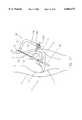
- FIG. 1is a diagrammatical sectional view of a human knee joint, with appropriate bone tunnels formed therein and with a ligament bone block disposed in one of the tunnels;
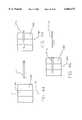
- FIG. 2is similar to FIG. 1, but illustrative of a metal wire insertion phase of the inventive method
- FIG. 3is similar to FIG. 2 but illustrative of completion of the metal wire insertion phase
- FIG. 4is similar to FIG. 3, but illustrative of a first metal wire withdrawal phase
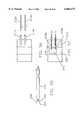
- FIG. 5is similar to FIG. 4, but illustrative of a first absorbable rod insertion phase
- FIG. 6is similar to FIG. 5, but illustrative of the first absorbable rod having been fully inserted;
- FIG. 7is similar to FIG. 6, but illustrative of a second metal wire withdrawal phase
- FIG. 8is similar to FIG. 7, but illustrative of a second absorbable rod insertion phase
- FIG. 9is similar to FIG. 8, but illustrative of the completion of the absorbable rod insertion phase of the inventive method
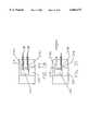
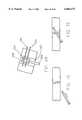
- FIG. 10is a side elevational view of one form of rack assembly for cross-pinning a bone block in a bone tunnel, illustrative of an embodiment of the invention.
- FIG. 11is a bottom view of the rack assembly of FIG. 10;
- FIG. 12is a bottom view of a trocar sleeve guide member portion of the rack assembly of FIGS. 10 and 11;
- FIG. 13is a side elevational view of the trocar sleeve guide member
- FIG. 14is a front elevational view of the trocar sleeve guide member
- FIG. 15is an interrupted side elevational view of a trocar portion of the rack assembly of FIG. 10;
- FIG. 16is an interrupted side elevational view, broken away and partly in section, of a trocar sleeve portion of the rack assembly of FIG. 10;
- FIG. 17is an end view of the trocar sleeve portion of FIG. 16;
- FIG. 18is a diagrammatical view of a human knee joint and illustrative of a step in a method in which the rack assembly of FIG. 10 is used;
- FIGS. 19-28are diagrammatical views illustrating a series of steps in the use of the rack assembly of FIG. 10;
- FIG. 29is a side elevational view of another form of rack assembly illustrative of an alternative embodiment of the invention.
- FIG. 30is a bottom view of the rack assembly of FIG. 29;
- FIG. 31is a bottom view of a trocar sleeve guide member portion of the rack assembly of FIG. 29;
- FIG. 32is a side elevational view of the trocar sleeve guide member
- FIG. 33is a front elevational view of the trocar sleeve guide member
- FIG. 34is a view similar to that of FIG. 18;
- FIGS. 35-40are diagrammatical views illustrating a series of steps in the use of the rack assembly of FIG. 29;
- FIG. 41is a side elevational view of a graft ligament, tendon or the like, wherein one end of the graft has been folded back upon itself and tack-stitched in place, and wherein a rod extending through the tissue is shown in phantom;
- FIG. 42is a side elevational view similar to FIG. 41, wherein the graft ligament, tendon or the like has been folded back upon itself, and wherein a rod extending between adjacent folds of the graft is shown in phantom;
- FIG. 43is a side elevational view similar to FIG. 42, wherein the folded tissue has been "whip stitched" together, and wherein a rod extending through the whip stitched tissue mass is shown in phantom;
- FIGS. 44-51are illustrative sectional side elevational views showing the steps of advancing a trocar/trocar sleeve combination into a bone and through a bone tunnel therein, removing the trocar, inserting a rod into the sleeve and across the bone tunnel, removing the sleeve, and pulling an end of a tissue graft around the rod located across the bone tunnel;
- FIGS. 52 and 53are illustrative side elevational views of representative bone blocks showing two possible examples of how a bone block may fracture during or after the placement of a cross-pin therethrough;
- FIG. 54is an illustrative sectional side elevational view of a bone block located in a partially closed ended bone tunnel and fixed in position by a rod extending across the bone tunnel between the bone block and the open end of the bone tunnel;
- FIG. 55is an illustrative side elevational view of an assembled trocar/trocar sleeve assembly for use in the present invention.
- FIGS. 56-63are illustrative side sectional, elevational views showing the use of long trocars inserted through sleeves, originally placed with the combination depicted in FIG. 55, to penetrate the bone and a bone block for the emplacement of rods to hold the bone block in place within the bone tunnel;
- FIG. 64is a side elevational view of a stepped trocar formed in accordance with the present invention.
- FIG. 65is a side elevational, sectional view showing a trocar sleeve having an internal stop adapted to limit the travel of a stepped trocar, as depicted in FIG. 64, therethrough;
- FIG. 66is an exploded, side sectional, elevational view illustrating the use of a plunger and tapping device for driving a rod through a sleeve in bone and into a bone block located in a bone tunnel;
- FIG. 67is a side elevational view of another trocar/trocar sleeve combination formed in accordance with the present invention.
- FIG. 68is a side elevational view of still another trocar/trocar sleeve combination formed in accordance with the present invention.
- FIG. 69is an illustrative perspective view showing an apertured head substituted for the enlarged cannulated sleeve head depicted in FIG. 19;
- FIGS. 70-74are illustrative side elevational views showing the disposition of a rod across a reduced bone fracture using a trocar/trocar sleeve combination formed in accordance with the present invention.
- a human knee joint 10including a femur 12 and tibia 14, has been provided with an appropriate femoral bone tunnel 16 and an appropriate tibial bone tunnel 18.
- Such tunnelsmay be provided in ways well known in the art.
- a bone block 20, having ligament material 22 attached thereto,has been positioned in femoral tunnel 16. Such bone block positioning may also be achieved in ways well known in the art.
- a first metal wire 30,which may be of the type commonly referred to as a guidewire or a "K-wire" is advanced through skin 31 and a first portion 32 of femur 12.
- First wire 30is advanced transversely of femoral tunnel 16 so as to intersect and extend through bone block 20, as shown in FIG. 2.
- a second metal wire 34is advanced through a second portion 36 of femur 12.
- Second wire 34is also advanced transversely of femoral tunnel 16 so as to also intersect and extend through bone block 20 (FIG. 3). At this point, bone block 20 is securely held in femoral tunnel 16 by the two spaced-apart metal wires 30, 34.
- one of the two wires 30, 34is then removed, while the other of the two wires 30, 34 is left in place in femur 12 and bone block 20.
- wire 30may be removed while wire 34 is left in place.
- a first absorbable rod 40(FIG. 5) is then advanced through the bore 42 left by the removal of first wire 30, such that first absorbable rod 40 extends through femur 12 and bone block 20 (FIG. 6). At this point, bone block 20 is securely held in femoral tunnel 16 by both metal wire 34 and first absorbable rod 40.
- the absorbable rods 40, 44may be made out of a material such as polylactic acid (PLA), polyglycolic acid (PGA), polydiaxanone (PDS), or out of some other such material which is formable into a relatively rigid and hard configuration, but which is absorbable by the body of the patient over time. If desired, the distal ends of absorbable rods 40, 44 can be pointed or rounded so as to facilitate their deployment into the body.
- PLApolylactic acid
- PGApolyglycolic acid
- PDSpolydiaxanone
- a bone blockis fixed within a bone tunnel, such that the bone block is anchored in the tunnel by cross-pins which are made out of a material which is absorbable by the body over time.
- the methodmay be exercised with any reasonable number of wires, exceeding one.
- the methodincludes the steps of placing the bone block in the bone tunnel, and then advancing a plurality of metal wires through the bone, transversely of the tunnel, so as to intercept the bone block and extend therethrough. At least one of the wires is then removed while leaving at least one of the wires in place, and that at least one removed wire is then replaced by at least one absorbable rod. At least one further of the wires is then removed and that at least one removed wire is then replaced by at least one further absorbable rod. The last-mentioned step is then repeated until a selected number of the metal wires is each replaced with an absorbable rod, whereby to retain the bone block in the bone tunnel with absorbable rods.
- FIGS. 1-9show metal wires 30, 34 and absorbable rods 40, 44 passing completely through bone block 20 during the cross-pinning procedure, it is also possible for metal wires 30, 34 and absorbable rods 40, 44 to pass only part way across bone block 20, if the same should be desired.
- various drill guideshave been developed for forming transverse passages through the femur and bone block so as to cross-pin the bone block within the femoral tunnel.
- inventive method of the present inventionmay be practiced using such known drill guides.
- present inventionmay also be practiced using a novel rack assembly formed in accordance with the present invention.
- Rack assembly 50comprises an L-shaped member 52 having a base portion 54 and an arm portion 56.
- the arm portion 56extends transversely, and preferably is normal to, base portion 54.
- Rack assembly 50also includes a cannulated sleeve 58 which, at a first end 60 thereof, is provided with an enlarged head portion 62, and which, at a second end 64 thereof, is releasably connectable to base portion 54 of L-shaped member 52.
- Sleeve 58may be retained in a bore 65 (FIG. 11) formed in base portion 54 by a set screw 66.
- a trocar sleeve guide member 70is removably connectable to arm portion 56 of L-shaped member 52.
- Trocar sleeve guide member 70is provided with bores 72 extending therethrough. Bores 72 extend substantially normal to a longitudinal axis 68 (FIG. 10) of the enlarged head portion 62 of cannulated sleeve 58.
- a set screw 71(FIG. 11) may be used to releasably retain trocar sleeve guide member 70 in position on arm portion 56.
- arm portion 56may be provided with stop means (not shown) for limiting the movement of the trocar sleeve guide member 70 along arm portion 56.
- Trocar sleeve guide member 70is preferably formed in two halves releasably held together by a set screw 73 (FIG. 11), whereby trocar sleeve guide member 70 can be slidably mounted on, or detached from, trocar sleeves 74, 76 passing through bores 72, as will hereinafter be discussed.
- First and second trocar sleeves 74, 76are slidably received by bores 72, such that sleeves 74, 76 are axially and rotatably movable in bores 72.
- trocar sleeve 74is provided with a collar portion 78 having a slot 80 formed therein.
- Sleeve 76is substantially identical to sleeve 74.
- Rack assembly 50also includes one or more trocars 82 (FIGS. 10 and 15) for disposition in the sleeves 74, 76.
- Each trocar 82is provided with a sharp end 84 (FIG. 15) for penetration of bone.
- a transversely-extending pin 86is provided near (but spaced from) the opposite end of the trocar 82. Pin 86 is fixed in place and is receivable by the slots 80 of trocar sleeves 74, 76 such that axial (in a distal direction) and rotational movement of trocar 82 causes similar movement of sleeves 74, 76.
- the first and second absorbable rods 40, 44are slidable through sleeves 74, 76, as will be further described hereinbelow.
- FIGS. 18-28illustrate how rack assembly 50 may be used to practice the present invention.
- FIG. 18there is shown a human knee joint 10 including femur 12 and tibia 14.
- An appropriate femoral tunnel 16 and an appropriate tibial tunnel 18have been provided, as by means and methods well known in the art.
- a guidewire 90extends through the bone tunnels 16, 18 as shown.
- the rack assembly's cannulated sleeve 58is fed over guidewire 90, through tibial tunnel 18 and into femoral tunnel 16, until the cannulated sleeve's head portion 62 engages an annular shoulder 92 in femoral tunnel 16 (FIG. 19).
- guidewire 90extends through a bore 94 (FIGS. 10 and 19) formed in base portion 54 of L-shaped member 52.
- the cannulated sleeve's head portion 62is preferably sized so as to form a snug fit in femoral tunnel 16.
- Cannulated sleeve 58may be positioned in the bone tunnels 16, 18 and then connected to L-shaped member 52 or, more preferably, cannulated sleeve 58 may be first connected to L-shaped member 52 and then positioned in femur 12 and tibia 14. Trocar sleeve guide member 70, if not already positioned on arm portion 56, is then fixed to arm portion 56, as by set screw 71 (FIG. 11).
- First trocar sleeve 74is then inserted in a bore 72 of guide member 70 (FIG. 20), and trocar 82 is extended through sleeve 74 until pin 86 (FIG. 15) of trocar 82 is nested in slot 80 (FIGS. 16 and 17) of sleeve 74, with the trocar's sharp end 84 extending beyond the distal end of sleeve 74 (FIG. 20).
- trocar 82may be mounted in first trocar sleeve 74 before first trocar sleeve 74 is mounted in a bore 72.
- trocar sleeve 74 and trocar 82is then drilled, as a unit, into femur 12 toward, but short of, the enlarged head portion 62 of cannulated sleeve 58 (FIG. 20).
- Trocar 82may then be withdrawn from first trocar sleeve 74 and placed in second trocar sleeve 76 (FIG. 21).
- a second trocar 82may be provided for second trocar sleeve 76.
- the combination of trocar sleeve 76 and trocar 82is then drilled, as a unit, into femur 12 toward, but short of, head portion 62 of cannulated sleeve 58.
- the rack's L-shaped member 52may then be removed from the surgical site. This may be accomplished by first loosening set screw 73 (FIG.
- trocar sleeves 74, 76will be freed from guide member 70, and then sliding cannulated sleeve 58 downward along guidewire 90 until the cannulated sleeve emerges from bone tunnels 16, 18. This procedure will leave trocar sleeves 74, 76 lodged in femur 12 (FIG. 22).
- Guidewire 90is then used to pull a suture 96, which is attached to bone block 20, up through tibial tunnel 18 and into femoral tunnel 16, until bone block 20 engages the annular shoulder 92 in femoral tunnel 16 (FIG. 23).
- Guidewire 90may be provided with an eyelet (not shown) adjacent to its proximal end so as to facilitate this procedure. Bone block 20 can then be held is this position by maintaining tension on the portion of suture 96 emerging from the top of femur 12.
- Trocar sleeve 76 and trocar 82are then drilled through bone block 20, as shown in FIG. 24.
- Trocar 82may then be removed from sleeve 76, placed in sleeve 74, and sleeve 74 and trocar 82 drilled through bone block 20, as shown in FIG. 25.
- the trocar 82(or trocars 82 if more than one trocar is used) may then be withdrawn from the sleeve 74 (or sleeves 74, 76).
- the first absorbable rod 40is then inserted, by sliding rod 40 through trocar sleeve 74 into a position extending through bone block 20 (FIG. 26).
- Sleeve 74may then be withdrawn from bone block 20 and femur 12, leaving first absorbable rod 40 in place in femur 12 and extending through bone block 20, as shown in FIG. 27.
- second absorbable rod 44is then slid into place through sleeve 76.
- Sleeve 76is then removed, leaving second absorbable rod 44, along with first absorbable rod 40, extending through bone block 20 so as to lock bone block 20 in place in femoral tunnel 16, as shown in FIG. 28.
- rack assembly 50with a guide member 70 which is not formed in two separable halves.
- guide member 70can simply be detached from L-shaped member 52 by unscrewing set screw 71.
- Guide member 70can then be left mounted on the outboard portions of sleeves 74, 76 until sleeves 74, 76 are withdrawn from the surgical site, with guide member 70 being removed with the last of the sleeves 74, 76.
- Rack assembly 100comprises an L-shaped member 102 having a base portion 104 and an arm portion 106. Arm portion 106 extends transversely of, and preferably is normal to, base portion 104.
- Rack assembly 100also includes a cannulated sleeve 108 which, at a base end 110 thereof, is connected to base portion 104.
- Cannulated sleeve 108may be retained in a bore 112 in base portion 104, as by screw threads or a set screw (not shown) or a press fit or the like.
- Cannulated sleeve 108is provided with a slot 114 (FIG. 29) extending substantially throughout the length of sleeve 108.
- Base portion 104 of L-shaped member 102is also provided with a slot 116 (FIG. 30) which is alignable with the sleeve's slot 114 so as to place the slots 114, 116 in communication with each other.
- a trocar sleeve guide member 120is removably connectable to arm portion 106 of L-shaped member 102.
- Trocar sleeve guide member 120is provided with bores 122 extending therethrough. Bores 122 extend substantially normal to a hypothetical extension of the longitudinal axis 124 of cannulated sleeve 108.
- a set screw 126(FIG. 30) may be used to releasably retain trocar sleeve guide member 120 in position on arm portion 106.
- arm portion 106may be provided with a stop means (not shown) for limiting movement of member 120 on arm portion 106.
- Trocar sleeve guide member 120is preferably formed in two halves releasably held together by a set screw 127 (FIG. 30), whereby trocar sleeve guide member 120 can be slidably mounted on, or detachable from, trocar sleeves 128, 130 passing through bores 122, as will hereinafter be discussed.
- First and second trocar sleeves 128, 130are received by bores 122, such that sleeves 128, 130 are axially and rotatably movable in bores 122.
- the two trocar sleeves 128, 130are substantially identical to the sleeve 74 shown in FIGS. 16 and 17.
- Rack assembly 100also includes one or more trocars 132 for disposition in sleeves 128, 130.
- the trocar 132is substantially identical to the trocar 82 shown in FIG. 15.
- the aforementioned first and second absorbable rods 40, 44are slidable through sleeves 128, 130.
- FIGS. 34-40illustrate how rack assembly 100 may be used to practice the present invention.
- bone tunnels 16 and 18are formed in femur 12 and tibia 18, respectively, and a guidewire 90 extends through bone tunnels 16, 18.
- Guidewire 90is then used to pull a suture 96, which is attached to bone block 20, up through tibial tunnel 18 and into femoral tunnel 16, such that bone block 20 is in engagement with annular shoulder 92 (FIG. 35). Bone block 20 is kept in this position by maintaining tension on the portion of suture 96 emerging from the top of femur 12.
- Suture 96is then introduced into the rack assembly's cannulated sleeve 108 and base portion 104 by way of slots 114, 116.
- Cannulated sleeve 108is then passed down the hole 133 (FIGS. 35 and 36) left by the removed guidewire 90 until the distal end of the cannulated sleeve engages the top end of bone block 20 (FIG. 36).
- first trocar sleeve 128is extended through a guide member bore 122 and a trocar 132 is inserted into sleeve 128.
- a trocar 132may be inserted into first trocar sleeve 128 before first trocar sleeve 128 is inserted into a guide member bore 122.
- the sleeve 128 and trocar 132are then drilled, as a unit, into femur 12. With bone block 20 held against shoulder 92 by pulling on suture 96, the combination of sleeve 128 and trocar 132 is drilled through bone block 20 (FIG. 36). In a similar manner, sleeve 130 and trocar 132 (either the same trocar used with sleeve 128 or another trocar) are then drilled through bone block 20, as shown in FIG. 37.
- L-shaped member 102 and cannulated sleeve 108are then removed from the surgical site. This may be accomplished by first loosening set screw 127 (FIG. 30) so as to separate trocar sleeve guide member 120 into its two halves, whereby trocar sleeves 128, 130 will be freed from guide member 120, and then sliding cannulated sleeve 108 upward and out of hole 133. Any trocars 132 are then removed, leaving the trocar sleeves 128, 130 extending into femur 12 and across bone block 20, as shown in FIG. 38.
- Second absorbable rod 44is then slid through sleeve 130 and sleeve 130 removed (FIG. 39), and first absorbable rod 40 is slid through sleeve 128 and sleeve 128 removed, leaving absorbable rods 40, 44 in place (FIG. 40) holding bone block 20 locked in femoral tunnel 16.
- Suture 96is then slipped through bone block 20 and removed, in the manner well known in the art.
- the present inventionis by no means limited to the application thereof as herein disclosed and/or as shown in the drawings.
- inventive method and apparatusare described herein and illustrated with reference to the human knee joint. It is foreseen that the method and apparatus described herein will be particularly beneficial with respect to such operations.
- the method and apparatus described hereinfind utility with respect to mammals generally, and with respect to other bones as, for example, in shoulder joints or the like.
- trocars 82 and 132 and their associated sleeves 74, 76 and 128, 130might be passed only part way through bone block 20, but not all the way through; or sleeves 74, 76 and/or sleeves 128, 130 might be stopped short of bone block 20 while trocars 82 and/or 132 penetrate into bone block 20.
- trocars 82 and 132are disclosed herein as being in the form of a hard rod with a sharp tip for penetrating bone.
- trocars 82 and 132might comprise guidewires or K-wires with a pyramidal front point.
- the inventionmight also be practiced with trocars 82 and 132 comprising a twist drill, a spade drill and/or some other sort of drill.
- trocars 82 and/or 132might be used with their associated rack assemblies 50 and 100, respectively, but without their associated sleeves 74, 76 and 128, 130, respectively. In this case, at least one trocar would always remain positioned in bone block 20 until at least one absorbable rod 40, 44 was positioned in the bone block.
- sleeve 74 and one trocar 82it is also possible to practice the present invention using just one sleeve 74 and one trocar 82, or just one sleeve 76 and one trocar 82; and it is possible to practice the invention using just one sleeve 128 and one trocar 132, or just one sleeve 130 and one trocar 132.
- the sleeve elementwould serve to retain the bone block in position within the bone tunnel while the trocar is replaced by the rod which will ultimately hold the bone block to the bone.
- the present applicationwill have utility with respect to setting cross-pins which may not necessarily be absorbable.
- the present inventionwill have utility wherever cross-pinning needs to be achieved for cross-pins which cannot be passed directly through the bone and/or bone block, e.g., where the cross-pins may be too soft or too brittle or too fragile to pass directly through the bone and/or bone block, or where the cross-pins may have a geometry which makes it difficult or impossible for them to be passed directly through the bone and/or bone block.
- the present inventionmight be used to set cross-pins made out of plastic and/or ceramic materials, or the present invention might be used to set cross-pins made out of metal.
- a portion of the piece of tissue alonemay be cross-pinned in a bone tunnel by any of the methods discussed above.
- the portion 150 of the piece of tissue 152 to be cross-pinned in the bone tunnelis preferably folded back upon itself one or more times.
- tacking stitches 154may be used to hold the layers 156 of folded tissue together while the resulting mass 150 is inserted or pulled into the bone tunnel in a manner similar to the procedures used to locate a bone block in a bone tunnel discussed above.
- cross-pinningproceeds substantially as discussed above, such that the rods 158 ultimately extend either through the tissue mass (see phantom lines in FIG. 41), or between the folded tissue layers (see phantom lines in FIG. 42), or both.
- the chances of the rod and/or sleeve and/or trocar tearing laterally out of, or longitudinally along, the tissue 152may be significant. This is particularly the case in those instances wherein the repair is to be subjected to substantial stress prior to complete healing. Accordingly, it is often desirable to reinforce the portion 150 of the tissue 152 to be cross-pinned within the bone tunnel. This may be accomplished in numerous ways well known to those skilled in the art. One such alternative, representatively shown in FIG. 43, is to "whip stitch" the portion 150 of the tissue 152 which is to be cross-pinned within the bone tunnel.
- the foregoing proceduresmay also be used to secure artificial grafts in the bone tunnel, i.e., grafts comprising an artificial prosthetic device not harvested from the body.
- itmay or may not be desirable to fold the graft back upon itself one or more times, in the manner shown in FIGS. 41-43, prior to cross-pinning.
- a portion 150 of a piece of tissue 152may be fixed in a bone tunnel by positioning a bio-absorbable rod 163 diametrically across the bone tunnel 164, and thereafter pulling the portion 150 of the piece of tissue 152 into an open end of the bone tunnel, around the rod 163 and back out the same open end of the bone tunnel. More particularly, as best seen in FIGS. 44-51, it has been found that the positioning of a bio-absorbable rod 163 diametrically across bone tunnel 164 is best accomplished with a trocar/sleeve combination 171 such as that illustratively shown in FIGS. 15-17.
- a trocar/sleeve combination 171be drilled in the manner discussed in detail above into bone 166, transversely to the longitudinal axis 172 (FIG. 44) of bone tunnel 164, diametrically through bone tunnel 164, and into bone 166 on the opposite side of bone tunnel 164 (see FIGS. 44 and 45).
- the trocar 171ais removed from sleeve 171b, and a bio-absorbable rod 163 is inserted into sleeve 171a so as to occupy a position extending across bone tunnel 164 (see FIGS. 46-48).
- Sleeve 171bis then removed from bone 166 and rod 163, leaving rod 163 extending from opening 168, diametrically across bone tunnel 164 and into opening 170 (see FIG. 49).
- one end 175 of a length of cord-like material, such as suture 173,is secured to an end 174 of piece of tissue 152 (FIG. 50).
- the other end 176 of the length of cord-like material 173is then threaded into an open end 178 of bone tunnel 164, and thence around rod 163, and then back out open end 178 of bone tunnel 164 (see FIG. 50).
- the free end 176 of the cord-like material 173is pulled so as to draw portion 150 of piece of tissue 152 into open end 178 of bone tunnel 164, around bio-absorbable rod 163, and back out open end 178 of bone tunnel 164.
- Tissue portion 150thus assumes a generally U-shape, having its closed end slidably secured in bone tunnel 164 by bio-absorbable rod 163, and its free ends extending outwardly from the same open end 178 of bone tunnel 164 (see FIG. 51).
- the foregoing proceduremay also be used to secure artificial grafts in the bone tunnel, i.e., grafts comprising an artificial prosthetic device not harvested from the body.
- bone blocksare relatively hard. This is frequently the case where the bone block is formed out of cortical bone.
- the bone blockmay fracture, as shown, for example, in FIGS. 52 and 53.
- the possibility of bone block fracturemay be reduced by reducing the diameter of the trocar/sleeve combination, and hence the resulting hole through the bone block, but this may in turn lead to an increase in the possibility of rod breakage when a load is applied to the graft ligament.
- the solutionutilizes the facts that (1) a bone block is significantly stronger in compression than it is in tension, and (2) a larger diameter rod will provide a stronger bone block fixation in a bone tunnel if bone block fracture is not an issue.
- the bone block 200is located at substantially closed end 202 of substantially blind bone tunnel 204, with its associated tissue graft 206 extending outwardly from the open end 208 of the substantially blind bone tunnel 204.
- a guide hole 201may extend through substantially closed end 202 of bone tunnel 204 so as to allow bone block 200 to be drawn into bone tunnel 204 by a cord-like element 203, or otherwise located in bone tunnel 204 as discussed hereinabove.
- a rod 208is then located diametrically across bone tunnel 204 adjacent to proximal end 210 of bone block 200.
- rod 208is positioned utilizing the same method as described above with regard to the threading of a portion of a piece of tissue over a rod extending diametrically through a bone tunnel (see FIGS. 44-51).
- the rod 208may pass through the tissue graft 208, or not, as desired. The result is that bone block 200 is reliably fixed in bone tunnel 206 between substantially closed tunnel end 202 and rod 208.
- the second of the above-mentioned alternativesproceeds from the premise that if the sleeve does not have to extend into or through the bone block, a significantly larger diameter rod may be used with a corresponding increase in the strength of the fixation of the bone block in the bone tunnel.
- This alternativeis representatively shown in FIGS. 56-63, which will be referred to specifically below.
- the trocar/sleeve combinations 210are drilled through the skin and into the bone in the same manner as discussed in detail above, and the bone block is located in the bone tunnel such that the various elements reside in a configuration generally as depicted in FIG. 22.
- the trocarsare disengaged from the sleeves, the bone block is pulled up into the bone tunnel (FIG. 23), and rods are inserted through (i) the sleeves and (ii) the bone located between the distal ends of the sleeves and the bone tunnel, and then into the bone block.
- a second, longer trocar 212a, 212bmay be inserted into each of the sleeves 214a, 214b and either drilled (FIG. 57) or tapped (FIG. 58) through the bone 216 located between the distal ends 218a, 218b of the sleeves 214a, 214b, and then into the bone tunnel 220 and into the bone block 222. Thereafter, one of the longer trocars 212 is removed (FIG. 59), and a metal, plastic, ceramic or bio-absorbable rod 224a is inserted into the bone and the bone block through the sleeve (FIG. 60).
- the longer trocars 212a and 212bare commonly stepped, e.g., in the manner shown in FIG. 24. More particularly, the longer trocars 212a commonly include a distal portion 230 having a smaller transverse cross-sectional diameter than their proximal portion 232, and define a distally-facing radial shoulder 234 at the joiner of their proximal and distal portions. In this way, the extent of trocar penetration beyond the distal ends of the sleeves is controlled by pre-selecting the axial length of the distal portion of the longer trocars.
- the longer trocarsare allowed to penetrate beyond the distal ends of the sleeves only to the point at which their distally-facing radial shoulders engage either the bone at the distal ends of the sleeves, or a radially-disposed, inward projection 236 formed on the sleeve side wall (FIG. 65).
- rigid rods 224a, 224bmay be driven through the sleeves 214a, 214b, through the bone 216 located between the sleeves and the bone tunnel 220, and then into the bone block 222 directly. This may be accomplished by, preferably, pointing or rounding the distal ends of the rods 224a, 224b, inserting the rods into the sleeves 214a, 214b, and using a plunger shaft 238 and tapping means 240 to drive the rods into position through the bone and into the bone block (FIG. 66).
- the radial shoulder 242(FIG. 55), formed by the distal end of the sleeve proximally of the pointed distal end 224 of the trocar extending distally thereof, can be a significant impediment to the passage of the interlocked trocar/sleeve combination into bone.
- this shoulderwhile normally only about 0.005 to 0.010 inch in radial thickness, has been noted to cause burning of the bone as the trocar/sleeve combination is advanced through the bone toward the bone tunnel.
- the distal edge 242 of the sleevecould be bevelled at an angle substantially equal to that of the adjacent trocar point 244 (see FIG. 67).
- Thisis not preferred, however, in view of the variations in machining tolerance commonly acceptable in the art in the formation of bevelled edges and trocar points.
- the chance of an exact mating of the trocar point with a bevelled sleeve endis unlikely.
- the bone burning problemand more generally the problem of the resistance to penetration of the trocar/sleeve combination into the bone, are still present in the embodiment shown in FIG. 67, albeit to a perhaps smaller degree than in the FIG. 55 embodiment.
- the distal end 246 of the sleeve 248should be slanted at an angle of approximately 15° proximally relative to a plane 250 located normal to the longitudinal axis 252 of the sleeve (see FIG. 68).
- the trocar point 256drills into the bone in the same manner as previously described, while the slanted distal end 246 of the sleeve 248 cuts into the sidewall of the hole formed by the trocar point, instead of rotating flat against the bone surrounding the hole being formed by the trocar.
- a bone drill which does not exhibit a tendency to bind, and/or to burn the bone during useis significantly more desirable than a bone drill which does bind or burn the bone during use.
- one preferred method of practicing the present inventionincludes the following steps:
- a flattened head 258(FIG. 69) defining a window 260 therethrough might be used in place of the enlarged head 62.
- the flattened head 258would extend substantially diametrically across the bone tunnel 262 in a plane transverse to an axial projection of the trocar/sleeve assemblies 264 being drilled into the bone.
- the window 260would be so disposed that the trocar/sleeve assemblies (or the trocars alone) could penetrate into the bone tunnel, through the window 260 in the head of the cannulated sleeve 266, and then into the bone on the opposite side of the bone tunnel.
- this embodiment of the present inventionis useful in any situation in which it is desired to form diametrically opposed openings in the sidewall of a bone tunnel.
- Particular examples of such situationsinclude those wherein the length of the sleeve and the length, and rigidity, of the rods are such that they may be relied upon to ensure that a rod entering the bone tunnel from the drill means entry side thereof will be maintained in alignment with, and engage, the opening on the other side of the bone tunnel.
- a rigid rodis passed through an object in a bone tunnel may find this alternative beneficial.
- the interlocking trocar/sleeve assemblies discussed hereinabovehave numerous other uses beyond the cross-pinning of objects in bone tunnels.
- One such illustrative useis in the placement of absorbable, or non-absorbable, pins across bone fractures so as to assist in maintaining broken bones in a desired healing relationship after fracture reduction procedures have been completed.
- this methodfollows the now well-understood steps of drilling a trocar/sleeve assembly into the desired position in bone, removing the trocar, inserting a rod into the sleeve, and then removing the sleeve from the bone and the rod.
- Other illustrative uses of the devices and concepts of the present inventionmay include, among others, the removal of tissue from the interior of bones, and/or the delivery of other things into the interior of a bone, such as other devices or prostheses, drugs, bone graft material, substitute bone marrow, and so on.
Landscapes
- Health & Medical Sciences (AREA)
- Orthopedic Medicine & Surgery (AREA)
- Life Sciences & Earth Sciences (AREA)
- Animal Behavior & Ethology (AREA)
- Veterinary Medicine (AREA)
- Rheumatology (AREA)
- Public Health (AREA)
- Oral & Maxillofacial Surgery (AREA)
- Engineering & Computer Science (AREA)
- Biomedical Technology (AREA)
- Heart & Thoracic Surgery (AREA)
- General Health & Medical Sciences (AREA)
- Transplantation (AREA)
- Vascular Medicine (AREA)
- Cardiology (AREA)
- Rehabilitation Therapy (AREA)
- Surgery (AREA)
- Dentistry (AREA)
- Nuclear Medicine, Radiotherapy & Molecular Imaging (AREA)
- Medical Informatics (AREA)
- Molecular Biology (AREA)
- Surgical Instruments (AREA)
- Prostheses (AREA)
- Orthopedics, Nursing, And Contraception (AREA)
Abstract
Description
Claims (42)
Priority Applications (11)
| Application Number | Priority Date | Filing Date | Title |
|---|---|---|---|
| US09/015,493US6066173A (en) | 1998-01-28 | 1998-01-28 | Method and apparatus for fixing a graft in a bone tunnel |
| CA002260457ACA2260457C (en) | 1998-01-28 | 1999-01-26 | Apparatus for fixing a graft in a bone tunnel and uses thereof |
| EP99300597AEP0931514B1 (en) | 1998-01-28 | 1999-01-27 | Apparatus for fixing a graft in a bone tunnel |
| JP01873999AJP4077100B2 (en) | 1998-01-28 | 1999-01-27 | Method and apparatus for securing tissue fragments in a tunnel |
| DE69930582TDE69930582T2 (en) | 1998-01-28 | 1999-01-27 | Device for securing a transplant in a bone tunnel |
| AU13246/99AAU762642B2 (en) | 1998-01-28 | 1999-01-27 | Method and apparatus for fixing a graft in a bone tunnel |
| US09/577,312US6716217B2 (en) | 1998-01-28 | 2000-05-23 | Method and apparatus for fixing a graft in a bone tunnel |
| US09/577,757US6379384B1 (en) | 1998-01-28 | 2000-05-23 | Method and apparatus for fixing a graft in a bone tunnel |
| US10/137,505US7056340B2 (en) | 1998-01-28 | 2002-04-30 | Method for fixing a graft in a bone tunnel |
| US10/818,860US20050010289A1 (en) | 1998-01-28 | 2004-04-06 | Method and apparatus for fixing a graft in a bone tunnel |
| US11/343,141US20060129162A1 (en) | 1998-01-28 | 2006-01-30 | Method and apparatus for fixing a graft in a bone tunnel |
Applications Claiming Priority (1)
| Application Number | Priority Date | Filing Date | Title |
|---|---|---|---|
| US09/015,493US6066173A (en) | 1998-01-28 | 1998-01-28 | Method and apparatus for fixing a graft in a bone tunnel |
Related Child Applications (3)
| Application Number | Title | Priority Date | Filing Date |
|---|---|---|---|
| US09/577,757DivisionUS6379384B1 (en) | 1998-01-28 | 2000-05-23 | Method and apparatus for fixing a graft in a bone tunnel |
| US09/577,312DivisionUS6716217B2 (en) | 1998-01-28 | 2000-05-23 | Method and apparatus for fixing a graft in a bone tunnel |
| US09/577,312ContinuationUS6716217B2 (en) | 1998-01-28 | 2000-05-23 | Method and apparatus for fixing a graft in a bone tunnel |
Publications (1)
| Publication Number | Publication Date |
|---|---|
| US6066173Atrue US6066173A (en) | 2000-05-23 |
Family
ID=37513854
Family Applications (6)
| Application Number | Title | Priority Date | Filing Date |
|---|---|---|---|
| US09/015,493Expired - LifetimeUS6066173A (en) | 1998-01-28 | 1998-01-28 | Method and apparatus for fixing a graft in a bone tunnel |
| US09/577,757Expired - LifetimeUS6379384B1 (en) | 1998-01-28 | 2000-05-23 | Method and apparatus for fixing a graft in a bone tunnel |
| US09/577,312Expired - LifetimeUS6716217B2 (en) | 1998-01-28 | 2000-05-23 | Method and apparatus for fixing a graft in a bone tunnel |
| US10/137,505Expired - LifetimeUS7056340B2 (en) | 1998-01-28 | 2002-04-30 | Method for fixing a graft in a bone tunnel |
| US10/818,860AbandonedUS20050010289A1 (en) | 1998-01-28 | 2004-04-06 | Method and apparatus for fixing a graft in a bone tunnel |
| US11/343,141AbandonedUS20060129162A1 (en) | 1998-01-28 | 2006-01-30 | Method and apparatus for fixing a graft in a bone tunnel |
Family Applications After (5)
| Application Number | Title | Priority Date | Filing Date |
|---|---|---|---|
| US09/577,757Expired - LifetimeUS6379384B1 (en) | 1998-01-28 | 2000-05-23 | Method and apparatus for fixing a graft in a bone tunnel |
| US09/577,312Expired - LifetimeUS6716217B2 (en) | 1998-01-28 | 2000-05-23 | Method and apparatus for fixing a graft in a bone tunnel |
| US10/137,505Expired - LifetimeUS7056340B2 (en) | 1998-01-28 | 2002-04-30 | Method for fixing a graft in a bone tunnel |
| US10/818,860AbandonedUS20050010289A1 (en) | 1998-01-28 | 2004-04-06 | Method and apparatus for fixing a graft in a bone tunnel |
| US11/343,141AbandonedUS20060129162A1 (en) | 1998-01-28 | 2006-01-30 | Method and apparatus for fixing a graft in a bone tunnel |
Country Status (6)
| Country | Link |
|---|---|
| US (6) | US6066173A (en) |
| EP (1) | EP0931514B1 (en) |
| JP (1) | JP4077100B2 (en) |
| AU (1) | AU762642B2 (en) |
| CA (1) | CA2260457C (en) |
| DE (1) | DE69930582T2 (en) |
Cited By (94)
| Publication number | Priority date | Publication date | Assignee | Title |
|---|---|---|---|---|
| US6306138B1 (en)* | 1997-09-24 | 2001-10-23 | Ethicon, Inc. | ACL fixation pin and method |
| US20030009217A1 (en)* | 1998-01-28 | 2003-01-09 | Mckernan Daniel J. | Method and apparatus for fixing a graft in a bone tunnel |
| US6540783B1 (en)* | 1998-01-28 | 2003-04-01 | Ethicon, Inc. | Method and apparatus for fixing a graft in a bone tunnel |
| WO2003028533A3 (en)* | 2001-10-01 | 2003-08-28 | Scandius Biomedical Inc | Apparatus and method for reconstructing a ligament |
| US20030216780A1 (en)* | 2002-05-15 | 2003-11-20 | Fitts Steven E. | Two piece cross-pin graft fixation |
| US20040049195A1 (en)* | 2002-05-15 | 2004-03-11 | Wamis Singhatat | Cross-pin graft fixation instruments and method |
| US20040087953A1 (en)* | 2002-05-15 | 2004-05-06 | Wamis Singhatat | Cross-pin graft fixation, instruments, and methods |
| US20040092936A1 (en)* | 2002-10-29 | 2004-05-13 | Stryker Endoscopy | Graft fixation device and method |
| US20040199163A1 (en)* | 2003-04-01 | 2004-10-07 | Whittaker Gregory R. | Method and apparatus for fixing a graft in a bone tunnel |
| US20040267273A1 (en)* | 2003-06-27 | 2004-12-30 | Whittaker Gregory R. | Adjustable drill guide assembly and method of use |
| US20050033301A1 (en)* | 2002-05-15 | 2005-02-10 | Guiseppe Lombardo | Cross-pin graft fixation, instruments, and methods |
| US20050071004A1 (en)* | 2001-10-01 | 2005-03-31 | Paul Re | Apparatus and method for reconstructing a ligament |
| US20050149187A1 (en)* | 2000-08-28 | 2005-07-07 | Ron Clark | Method and implant for securing ligament replacement into the knee |
| US20050197662A1 (en)* | 2000-08-28 | 2005-09-08 | Ron Clark | Method and implant for securing ligament replacement into the knee |
| US20050203621A1 (en)* | 2002-03-08 | 2005-09-15 | Musculoskeletal Transplant Foundation | Method for inserting improved bone tendon bone assembly with allograft bone block |
| US6994725B1 (en)* | 2000-10-03 | 2006-02-07 | Medicinelodge, Inc. | Method and apparatus for reconstructing a ligament |
| US7033364B1 (en) | 2002-01-31 | 2006-04-25 | Arthrotek, Inc. | Apparatus and method for manipulating a flexible strand and soft tissue replacement during surgery |
| US20060149259A1 (en)* | 2004-12-21 | 2006-07-06 | May Thomas C | Method of replacing an anterior cruciate ligament in the knee |
| US20060173465A1 (en)* | 2002-01-31 | 2006-08-03 | Arthrotek, Inc. | Apparatus and method for manipulating a flexible strand and soft tissue replacement during surgery |
| US7341592B1 (en) | 2003-10-15 | 2008-03-11 | Biomet Sports Medicine, Inc. | Method and apparatus for graft fixation |
| US20080103506A1 (en)* | 2006-10-30 | 2008-05-01 | Depuy Mitek, Inc. | Methods and devices for ligament repair |
| US20080228271A1 (en)* | 2007-03-13 | 2008-09-18 | Biomet Sports Medicine, Inc. | Method and apparatus for graft fixation |
| US7488347B1 (en) | 2005-01-06 | 2009-02-10 | Medicine Lodge, Inc. | Transosseous graft retention system and method |
| US7641694B1 (en) | 2005-01-06 | 2010-01-05 | IMDS, Inc. | Line lock graft retention system and method |
| US20100030222A1 (en)* | 2001-03-13 | 2010-02-04 | Depuy Mitek, Inc. | Method and apparatus for fixing a graft in a bone tunnel |
| US20100057142A1 (en)* | 2001-03-13 | 2010-03-04 | Depuy Mitek, Inc. | Method and apparatus for fixing a graft in a bone tunnel |
| US20100121447A1 (en)* | 2008-10-10 | 2010-05-13 | Marcus Troger | Method for replacing a ligament in a knee |
| US7896917B2 (en) | 2003-10-15 | 2011-03-01 | Biomet Sports Medicine, Llc | Method and apparatus for graft fixation |
| US20110098727A1 (en)* | 2006-09-29 | 2011-04-28 | Biomet Sports Medicine, Llc | Method and Apparatus for Securing Soft Tissue to Bone |
| US20110106153A1 (en)* | 2006-02-03 | 2011-05-05 | Biomet Sports Medicine, Llc | Method and Apparatus for Sternal Closure |
| US8002778B1 (en) | 2004-06-28 | 2011-08-23 | Biomet Sports Medicine, Llc | Crosspin and method for inserting the same during soft ligament repair |
| US8226716B2 (en) | 2001-03-13 | 2012-07-24 | Depuy Mitek, Inc. | Method and apparatus for fixing a graft in a bone tunnel |
| US8382835B2 (en) | 2002-01-31 | 2013-02-26 | Biomet Sports Medicine, Llc | Apparatus and method for manipulating a flexible strand and soft tissue replacement during surgery |
| US8551140B2 (en) | 2004-11-05 | 2013-10-08 | Biomet Sports Medicine, Llc | Method and apparatus for coupling soft tissue to bone |
| US8562645B2 (en) | 2006-09-29 | 2013-10-22 | Biomet Sports Medicine, Llc | Method and apparatus for forming a self-locking adjustable loop |
| US8574235B2 (en) | 2006-02-03 | 2013-11-05 | Biomet Sports Medicine, Llc | Method for trochanteric reattachment |
| US20130325011A1 (en)* | 2012-06-04 | 2013-12-05 | Depuy Mitek, Inc. | Methods and Devices for Forming Bone Tunnels |
| US8608777B2 (en) | 2006-02-03 | 2013-12-17 | Biomet Sports Medicine | Method and apparatus for coupling soft tissue to a bone |
| US8617176B2 (en) | 2011-08-24 | 2013-12-31 | Depuy Mitek, Llc | Cross pinning guide devices and methods |
| US8632569B2 (en) | 2006-02-03 | 2014-01-21 | Biomet Sports Medicine, Llc | Soft tissue repair device and associated methods |
| US8652171B2 (en) | 2006-02-03 | 2014-02-18 | Biomet Sports Medicine, Llc | Method and apparatus for soft tissue fixation |
| US8652172B2 (en) | 2006-02-03 | 2014-02-18 | Biomet Sports Medicine, Llc | Flexible anchors for tissue fixation |
| US8672968B2 (en) | 2006-09-29 | 2014-03-18 | Biomet Sports Medicine, Llc | Method for implanting soft tissue |
| US8771352B2 (en) | 2011-05-17 | 2014-07-08 | Biomet Sports Medicine, Llc | Method and apparatus for tibial fixation of an ACL graft |
| US8777956B2 (en) | 2006-08-16 | 2014-07-15 | Biomet Sports Medicine, Llc | Chondral defect repair |
| US8801783B2 (en) | 2006-09-29 | 2014-08-12 | Biomet Sports Medicine, Llc | Prosthetic ligament system for knee joint |
| US8840645B2 (en) | 2004-11-05 | 2014-09-23 | Biomet Sports Medicine, Llc | Method and apparatus for coupling soft tissue to a bone |
| US8876837B2 (en) | 2010-03-05 | 2014-11-04 | Biomet Manufacturing, Llc | Method and apparatus for implanting a modular femoral hip |
| US8900314B2 (en) | 2009-05-28 | 2014-12-02 | Biomet Manufacturing, Llc | Method of implanting a prosthetic knee joint assembly |
| US8906109B2 (en) | 2010-03-05 | 2014-12-09 | Biomet Manufacturing, Llc | Modular lateral hip augments |
| US8932331B2 (en) | 2006-02-03 | 2015-01-13 | Biomet Sports Medicine, Llc | Method and apparatus for coupling soft tissue to bone |
| US8936621B2 (en) | 2006-02-03 | 2015-01-20 | Biomet Sports Medicine, Llc | Method and apparatus for forming a self-locking adjustable loop |
| US8998949B2 (en) | 2004-11-09 | 2015-04-07 | Biomet Sports Medicine, Llc | Soft tissue conduit device |
| US9017381B2 (en) | 2007-04-10 | 2015-04-28 | Biomet Sports Medicine, Llc | Adjustable knotless loops |
| US9138273B2 (en) | 2010-03-05 | 2015-09-22 | Biomet Manufacturing, Llc | Guide assembly for lateral implants and associated methods |
| US9149267B2 (en) | 2006-02-03 | 2015-10-06 | Biomet Sports Medicine, Llc | Method and apparatus for coupling soft tissue to a bone |
| US9173651B2 (en) | 2006-02-03 | 2015-11-03 | Biomet Sports Medicine, Llc | Soft tissue repair device and associated methods |
| US9265498B2 (en) | 2003-06-11 | 2016-02-23 | Imds Llc | Compact line locks and methods |
| US9314287B2 (en) | 2010-03-05 | 2016-04-19 | Biomet Manufacturing, Llc | Assembly tool for modular implant and associated method |
| US9314241B2 (en) | 2011-11-10 | 2016-04-19 | Biomet Sports Medicine, Llc | Apparatus for coupling soft tissue to a bone |
| US9339318B2 (en) | 2010-03-05 | 2016-05-17 | Biomet Manufacturing, Llc | Method and apparatus for preparing a proximal femur |
| US9357991B2 (en) | 2011-11-03 | 2016-06-07 | Biomet Sports Medicine, Llc | Method and apparatus for stitching tendons |
| US9370350B2 (en) | 2011-11-10 | 2016-06-21 | Biomet Sports Medicine, Llc | Apparatus for coupling soft tissue to a bone |
| US9381013B2 (en) | 2011-11-10 | 2016-07-05 | Biomet Sports Medicine, Llc | Method for coupling soft tissue to a bone |
| US9402621B2 (en) | 2006-02-03 | 2016-08-02 | Biomet Sports Medicine, LLC. | Method for tissue fixation |
| US9414833B2 (en) | 2006-02-03 | 2016-08-16 | Biomet Sports Medicine, Llc | Soft tissue repair assembly and associated method |
| US9414925B2 (en) | 2006-09-29 | 2016-08-16 | Biomet Manufacturing, Llc | Method of implanting a knee prosthesis assembly with a ligament link |
| US9445827B2 (en) | 2011-10-25 | 2016-09-20 | Biomet Sports Medicine, Llc | Method and apparatus for intraosseous membrane reconstruction |
| US9492158B2 (en) | 2006-02-03 | 2016-11-15 | Biomet Sports Medicine, Llc | Method and apparatus for coupling soft tissue to a bone |
| US9504460B2 (en) | 2004-11-05 | 2016-11-29 | Biomet Sports Medicine, LLC. | Soft tissue repair device and method |
| US9538998B2 (en) | 2006-02-03 | 2017-01-10 | Biomet Sports Medicine, Llc | Method and apparatus for fracture fixation |
| US9572655B2 (en) | 2004-11-05 | 2017-02-21 | Biomet Sports Medicine, Llc | Method and apparatus for coupling soft tissue to a bone |
| US9615942B2 (en) | 2010-03-05 | 2017-04-11 | Biomet Manufacturing, Llc | Method and apparatus for trialing and implanting a modular femoral hip |
| US9615822B2 (en) | 2014-05-30 | 2017-04-11 | Biomet Sports Medicine, Llc | Insertion tools and method for soft anchor |
| US9700291B2 (en) | 2014-06-03 | 2017-07-11 | Biomet Sports Medicine, Llc | Capsule retractor |
| US9757119B2 (en) | 2013-03-08 | 2017-09-12 | Biomet Sports Medicine, Llc | Visual aid for identifying suture limbs arthroscopically |
| US9788876B2 (en) | 2006-09-29 | 2017-10-17 | Biomet Sports Medicine, Llc | Fracture fixation device |
| US9801708B2 (en) | 2004-11-05 | 2017-10-31 | Biomet Sports Medicine, Llc | Method and apparatus for coupling soft tissue to a bone |
| US9918826B2 (en) | 2006-09-29 | 2018-03-20 | Biomet Sports Medicine, Llc | Scaffold for spring ligament repair |
| US9918827B2 (en) | 2013-03-14 | 2018-03-20 | Biomet Sports Medicine, Llc | Scaffold for spring ligament repair |
| US9955980B2 (en) | 2015-02-24 | 2018-05-01 | Biomet Sports Medicine, Llc | Anatomic soft tissue repair |
| US10004588B2 (en) | 2006-02-03 | 2018-06-26 | Biomet Sports Medicine, Llc | Method and apparatus for fixation of an ACL graft |
| US10039543B2 (en) | 2014-08-22 | 2018-08-07 | Biomet Sports Medicine, Llc | Non-sliding soft anchor |
| US10136886B2 (en) | 2013-12-20 | 2018-11-27 | Biomet Sports Medicine, Llc | Knotless soft tissue devices and techniques |
| US10349931B2 (en) | 2006-09-29 | 2019-07-16 | Biomet Sports Medicine, Llc | Fracture fixation device |
| US10517587B2 (en) | 2006-02-03 | 2019-12-31 | Biomet Sports Medicine, Llc | Method and apparatus for forming a self-locking adjustable loop |
| US10912551B2 (en) | 2015-03-31 | 2021-02-09 | Biomet Sports Medicine, Llc | Suture anchor with soft anchor of electrospun fibers |
| US11259794B2 (en) | 2006-09-29 | 2022-03-01 | Biomet Sports Medicine, Llc | Method for implanting soft tissue |
| US11259792B2 (en) | 2006-02-03 | 2022-03-01 | Biomet Sports Medicine, Llc | Method and apparatus for coupling anatomical features |
| US11311287B2 (en) | 2006-02-03 | 2022-04-26 | Biomet Sports Medicine, Llc | Method for tissue fixation |
| US12096928B2 (en) | 2009-05-29 | 2024-09-24 | Biomet Sports Medicine, Llc | Method and apparatus for coupling soft tissue to a bone |
| US12245759B2 (en) | 2008-08-22 | 2025-03-11 | Biomet Sports Medicine, Llc | Method and apparatus for coupling soft tissue to bone |
| US12329373B2 (en) | 2011-05-02 | 2025-06-17 | Biomet Sports Medicine, Llc | Method and apparatus for soft tissue fixation |
| US12419632B2 (en) | 2008-08-22 | 2025-09-23 | Biomet Sports Medicine, Llc | Method and apparatus for coupling anatomical features |
Families Citing this family (49)
| Publication number | Priority date | Publication date | Assignee | Title |
|---|---|---|---|---|
| US6752830B1 (en)* | 1999-07-20 | 2004-06-22 | Ethicon, Inc. | Apparatus and method for reconstructing a ligament |
| DE60032152T2 (en) | 1999-08-10 | 2007-09-27 | Ethicon, Inc. | DEVICE FOR RESTORING A LIGAMENT |
| EP1769750A1 (en)* | 1999-08-10 | 2007-04-04 | Ethicon, Inc. | Apparatus for reconstructing a ligament |
| AU2001251700A1 (en)* | 2000-02-23 | 2001-09-03 | Ethicon Inc. | Apparatus and method for reconstructing a ligament |
| WO2003099148A2 (en)* | 2002-05-21 | 2003-12-04 | Sdgi Holdings, Inc. | Vertebrae bone anchor and cable for coupling it to a rod |
| US7195617B2 (en)* | 2004-03-03 | 2007-03-27 | Six-O, Ltd. | Device for collecting surgical material |
| US8088128B2 (en) | 2004-03-25 | 2012-01-03 | Depuy Mitek, Inc. | Implantable cross-pin for anterior cruciate ligament repair |
| US7468074B2 (en)* | 2004-10-29 | 2008-12-23 | Arthrex, Inc. | Ligament fixation using graft harness |
| US7833244B2 (en)* | 2005-04-20 | 2010-11-16 | Arthroscopic Innovations Llc | Suture fixation device and method for surgical repair |
| WO2007011755A2 (en)* | 2005-07-14 | 2007-01-25 | Globus Medical, Inc. | Vertebral marker devices and installation methods |
| WO2007053516A2 (en)* | 2005-10-28 | 2007-05-10 | Halkey-Roberts Corporation | Tapered anchor for tendon graft |
| ATE481039T1 (en) | 2005-11-10 | 2010-10-15 | Arthrex Inc | DEVICE FOR RESTORING THE ANTERIOR CRUCIAL LIGAMENT USING A DRILL FOR RETROGRADE SHAPING OF CANALS |
| US7736364B2 (en)* | 2006-02-02 | 2010-06-15 | Biomet Sports Medicine, Llc | Method and apparatus for performing ACL reconstruction |
| US7756244B2 (en)* | 2006-06-22 | 2010-07-13 | Varian Medical Systems, Inc. | Systems and methods for determining object position |
| US7942914B2 (en)* | 2006-10-17 | 2011-05-17 | Arthroscopic Innovations Llc | Method and apparatus for surgical repair |
| US8328875B2 (en) | 2009-12-30 | 2012-12-11 | Linares Medical Devices, Llc | Combination male/female hip joint and installation kit |
| US8211182B2 (en)* | 2007-09-17 | 2012-07-03 | Linares Medical Devices, Llc | Hip socket with assembleable male ball shape having integrally formed ligament and female receiver and installation kit |
| EP2203132A4 (en)* | 2007-09-17 | 2012-11-28 | Linares Medical Devices Llc | Artificial ligaments for joint applications |
| US8394103B2 (en)* | 2007-10-16 | 2013-03-12 | Biomet Manufacturing Corp. | Method and apparatus for orthopedic fixation |
| US20090149858A1 (en)* | 2007-12-05 | 2009-06-11 | Biomet Sports Medicine, Inc. | Method And Apparatus For Forming A Bone Tunnel |
| US20100329490A1 (en)* | 2008-02-20 | 2010-12-30 | Koninklijke Philips Electronics N.V. | Audio device and method of operation therefor |
| US20090281526A1 (en)* | 2008-05-09 | 2009-11-12 | Tyco Healthcare Group Lp | Negative Pressure Wound Therapy Apparatus Including a Fluid Line Coupling |
| US20100121375A1 (en)* | 2008-11-13 | 2010-05-13 | Pandya Rajiv D | Suture anchoring system and method |
| CN102481187B (en)* | 2009-03-31 | 2016-06-08 | 医学嵌入公司暨Imds共同创新公司 | Double bundle acl is repaired |
| US8535377B2 (en)* | 2009-03-31 | 2013-09-17 | Imds Corporation | Double bundle ACL repair system |
| US20110118838A1 (en)* | 2009-11-16 | 2011-05-19 | George Delli-Santi | Graft pulley and methods of use |
| US8449612B2 (en) | 2009-11-16 | 2013-05-28 | Arthrocare Corporation | Graft pulley and methods of use |
| US20150335440A1 (en) | 2011-08-23 | 2015-11-26 | Linares Medical Devices, Llc | Multi-component implant assembly with dual articulating and/or rotating surfaces |
| US8702800B2 (en) | 2011-08-23 | 2014-04-22 | Linares Medical Devices, Llc | Multi-component shoulder implant assembly with dual articulating surfaces |
| US8864835B2 (en) | 2011-08-24 | 2014-10-21 | Linares Medical Devices, Llc | Multi-component knee implant assembly with multiple articulating and traveling surfaces |
| US8702802B2 (en) | 2011-08-29 | 2014-04-22 | Linares Medical Devices, Llc | Knee implant assembly with rotary bearing supported and traveling surfaces |
| US8753403B2 (en) | 2011-08-30 | 2014-06-17 | Linares Medical Devices, Llc | Multi-component knee implant assembly with combined articulating and belt support and traveling surfaces |
| US8968402B2 (en) | 2011-10-18 | 2015-03-03 | Arthrocare Corporation | ACL implants, instruments, and methods |
| EP4252686A3 (en) | 2012-12-28 | 2023-12-27 | Paragon 28, Inc. | Alignment guide apparatus |
| EP3197378B1 (en)* | 2014-09-26 | 2021-03-03 | RMD Enterprises Group LLC | Transosseous ribbon wire devices |
| US11376079B2 (en) | 2016-02-19 | 2022-07-05 | Rajiv D. Pandya | System and technique for accessing extra articular lesions or abnormalities or intra osseous lesions or bone marrow lesions |
| US10064632B2 (en) | 2016-02-19 | 2018-09-04 | Rajiv D. Pandya | System and technique for accessing extra articular lesions or abnormalities or intra osseous lesions or bone marrow lesions |
| US9925010B2 (en) | 2016-02-19 | 2018-03-27 | Rajiv D. Pandya | System and technique for accessing extra articular lesions or abnormalities or intra osseous lesions or bone marrow lesions |
| US11419684B2 (en) | 2016-02-19 | 2022-08-23 | Rajiv D. Pandya | System and technique for accessing extra articular lesions or abnormalities or intra osseous lesions or bone marrow lesions |
| EP3528716B1 (en) | 2016-10-24 | 2024-02-14 | Paragon 28, Inc. | Osteotomy systems |
| EP3585287B1 (en) | 2017-02-27 | 2024-11-13 | Paragon 28, Inc. | Intramedullary nail fixation systems |
| ES2993743T3 (en) | 2017-02-27 | 2025-01-08 | Paragon 28 Inc | Targeting instruments and systems |
| US10918431B2 (en) | 2017-03-30 | 2021-02-16 | Paragon 28, Inc. | Bone fixation system, assembly, implants, devices, alignment guides, and methods of use |
| US10405889B2 (en)* | 2018-06-14 | 2019-09-10 | New Standard Device, LLC | Cold forged cutting tip for orthopedic wires and pins |
| EP3820382B1 (en) | 2018-07-11 | 2025-09-10 | Paragon 28, Inc. | Systems comprising alignment guides and implants |
| EP3923842A4 (en) | 2019-02-13 | 2022-11-23 | Paragon 28, Inc. | IMPLANTS, ALIGNMENT GUIDES, SYSTEMS AND METHODS OF USE |
| JP7562547B2 (en) | 2019-02-14 | 2024-10-07 | パラゴン28・インコーポレイテッド | Threaded targeting instruments, systems, and methods of use |
| AU2020228309B2 (en) | 2019-02-28 | 2025-10-02 | Paragon 28, Inc. | Fusion systems, instruments, bone plates and methods of use |
| US11963688B2 (en) | 2021-11-20 | 2024-04-23 | Panorthopaedics, Inc. | Device adapted for lateral engagement of an elongated member |
Citations (26)
| Publication number | Priority date | Publication date | Assignee | Title |
|---|---|---|---|---|
| US3973277A (en)* | 1974-01-30 | 1976-08-10 | James Campbell Semple | Attaching fibrous connective tissue to bone |
| US4858603A (en)* | 1988-06-06 | 1989-08-22 | Johnson & Johnson Orthopaedics, Inc. | Bone pin |
| US4901711A (en)* | 1988-12-27 | 1990-02-20 | Marlowe Goble E | Drill guide |
| US4944742A (en)* | 1988-06-06 | 1990-07-31 | Johnson & Johnson Orthopaedics, Inc. | Bone pin |
| US4985032A (en)* | 1990-05-14 | 1991-01-15 | Marlowe Goble E | Drill guide |
| US5004474A (en)* | 1989-11-28 | 1991-04-02 | Baxter International Inc. | Prosthetic anterior cruciate ligament design |
| US5067962A (en)* | 1989-04-18 | 1991-11-26 | Baxter International Inc. | Bioprosthetic ligament |
| US5147362A (en)* | 1991-04-08 | 1992-09-15 | Marlowe Goble E | Endosteal ligament fixation device |
| US5152764A (en)* | 1992-05-18 | 1992-10-06 | Marlowe Goble E | Femoral tunnel entry drill guide |
| US5234434A (en)* | 1992-08-17 | 1993-08-10 | Marlowe Goble E | Mutliple guide sleeve drill guide |
| US5266075A (en)* | 1992-10-05 | 1993-11-30 | Roy Clark | Tendon threader for endosteal ligament mounting |
| US5350380A (en)* | 1993-01-15 | 1994-09-27 | Depuy Inc. | Method for securing a ligament replacement in a bone |
| US5354300A (en)* | 1993-01-15 | 1994-10-11 | Depuy Inc. | Drill guide apparatus for installing a transverse pin |
| US5356435A (en)* | 1991-05-13 | 1994-10-18 | Cendis Medical | Element for fixing ligaments |
| US5356413A (en)* | 1993-03-12 | 1994-10-18 | Mitek Surgical Products, Inc. | Surgical anchor and method for deploying the same |
| US5364400A (en)* | 1992-02-14 | 1994-11-15 | American Cyanamid Co. | Interference implant |
| US5372599A (en)* | 1993-03-12 | 1994-12-13 | Mitek Surgical Products, Inc. | Surgical anchor and method for deploying the same |
| US5376119A (en)* | 1992-11-02 | 1994-12-27 | Protek Ag | Attachment for an artificial ligament, and a process for implantation |
| US5397356A (en)* | 1993-01-15 | 1995-03-14 | Depuy Inc. | Pin for securing a replacement ligament to a bone |
| US5431651A (en)* | 1993-02-08 | 1995-07-11 | Goble; E. Marlowe | Cross pin and set screw femoral and tibial fixation method |
| US5470334A (en)* | 1991-03-05 | 1995-11-28 | Linvatec Corporation | Bioabsorbable interference bone fixation screw |
| US5522817A (en)* | 1989-03-31 | 1996-06-04 | United States Surgical Corporation | Absorbable surgical fastener with bone penetrating elements |
| US5643266A (en)* | 1995-06-05 | 1997-07-01 | Li Medical Technologies, Inc. | Method and apparatus for securing ligaments |
| US5688284A (en)* | 1996-09-20 | 1997-11-18 | Medicinelodge, Inc. | Variable angle drill guide and ligament fixation method |
| US5697933A (en)* | 1995-12-18 | 1997-12-16 | Medicinelodge, Inc. | Bone-tendon-bone drill guide |
| US5918604A (en)* | 1997-02-12 | 1999-07-06 | Arthrex, Inc. | Method of loading tendons into the knee |
Family Cites Families (26)
| Publication number | Priority date | Publication date | Assignee | Title |
|---|---|---|---|---|
| US4257411A (en) | 1979-02-08 | 1981-03-24 | Cho Kenneth O | Cruciate ligament surgical drill guide |
| FR2598311B1 (en)* | 1986-05-07 | 1988-09-09 | Laboureau Jacques | SURGICAL INSTRUMENT FOR FOCUSING AND PLACING THE PLASTY (OR PROSTHETIC REPLACEMENT) OF THE LIGAMENT CROSS POSTERIOR KNEE |
| US4898156A (en) | 1987-05-18 | 1990-02-06 | Mitek Surgical Products, Inc. | Suture anchor |
| ES2007211A6 (en)* | 1987-05-27 | 1989-06-01 | Zahnradfabrik Friedrichshafen | Control device. |
| US4899743A (en) | 1987-12-15 | 1990-02-13 | Mitek Surgical Products, Inc. | Suture anchor installation tool |
| US4968315A (en) | 1987-12-15 | 1990-11-06 | Mitek Surgical Products, Inc. | Suture anchor and suture anchor installation tool |
| JPH0451780Y2 (en)* | 1988-03-05 | 1992-12-07 | ||
| US4950270A (en) | 1989-02-03 | 1990-08-21 | Boehringer Mannheim Corporation | Cannulated self-tapping bone screw |
| DE3928524C2 (en)* | 1989-08-29 | 1994-02-24 | Megaplast Dosiersysteme | donor |
| WO1991007356A1 (en)* | 1989-11-16 | 1991-05-30 | Libbey-Owens-Ford Co. | Infrared and ultraviolet radiation absorbing green glass composition |
| US5180388A (en)* | 1990-06-28 | 1993-01-19 | American Cyanamid Company | Bone pinning system |
| US5300077A (en)* | 1990-07-16 | 1994-04-05 | Arthrotek | Method and instruments for ACL reconstruction |
| US6019767A (en)* | 1990-07-16 | 2000-02-01 | Arthrotek | Tibial guide |
| US5115173A (en) | 1990-07-30 | 1992-05-19 | Kawasaki Jukogyo Kabushiki Kaisha | Air gap controlling system for linear motor |
| DE69106260T2 (en) | 1990-07-31 | 1995-08-10 | Sharp Kk | Paper feed device. |
| US5376129A (en)* | 1990-12-04 | 1994-12-27 | Board Of Regents, The University Of Texas System | Method and apparatus for making prosthetic socket preforms, prosthetic sockets, and socket attachment component |
| JP2619760B2 (en)* | 1991-12-25 | 1997-06-11 | グンゼ株式会社 | Bone treatment device and method for producing the same |
| US5672158A (en) | 1992-01-07 | 1997-09-30 | Sherwood Medical Company | Catheter introducer |
| EP0589592A3 (en)* | 1992-09-22 | 1994-10-19 | Orthofix Srl | Centering means for holes of intramedullary nails. |
| US5674224A (en)* | 1994-11-18 | 1997-10-07 | Howell; Stephen M. | Bone mulch screw assembly for endosteal fixation of soft tissue grafts and method for using same |
| US5891150A (en)* | 1996-12-04 | 1999-04-06 | Chan; Kwan-Ho | Apparatus and method for fixing a ligament in a bone tunnel |
| US5849013A (en)* | 1997-01-14 | 1998-12-15 | Whittaker; Gregory R. | Method and apparatus for fixing a bone block in a bone tunnel |
| US6113604A (en)* | 1997-01-14 | 2000-09-05 | Ethicon, Inc. | Method and apparatus for fixing a graft in a bone tunnel |
| WO1999015095A1 (en)* | 1997-09-24 | 1999-04-01 | Depuy Orthopaedics, Inc. | Acl fixation pin and method |
| US6066173A (en)* | 1998-01-28 | 2000-05-23 | Ethicon, Inc. | Method and apparatus for fixing a graft in a bone tunnel |
| US6517546B2 (en)* | 2001-03-13 | 2003-02-11 | Gregory R. Whittaker | Method and apparatus for fixing a graft in a bone tunnel |
- 1998
- 1998-01-28USUS09/015,493patent/US6066173A/ennot_activeExpired - Lifetime
- 1999
- 1999-01-26CACA002260457Apatent/CA2260457C/ennot_activeExpired - Fee Related
- 1999-01-27JPJP01873999Apatent/JP4077100B2/ennot_activeExpired - Lifetime
- 1999-01-27AUAU13246/99Apatent/AU762642B2/ennot_activeCeased
- 1999-01-27EPEP99300597Apatent/EP0931514B1/ennot_activeExpired - Lifetime
- 1999-01-27DEDE69930582Tpatent/DE69930582T2/ennot_activeExpired - Lifetime
- 2000
- 2000-05-23USUS09/577,757patent/US6379384B1/ennot_activeExpired - Lifetime
- 2000-05-23USUS09/577,312patent/US6716217B2/ennot_activeExpired - Lifetime
- 2002
- 2002-04-30USUS10/137,505patent/US7056340B2/ennot_activeExpired - Lifetime
- 2004
- 2004-04-06USUS10/818,860patent/US20050010289A1/ennot_activeAbandoned
- 2006
- 2006-01-30USUS11/343,141patent/US20060129162A1/ennot_activeAbandoned
Patent Citations (27)
| Publication number | Priority date | Publication date | Assignee | Title |
|---|---|---|---|---|
| US3973277A (en)* | 1974-01-30 | 1976-08-10 | James Campbell Semple | Attaching fibrous connective tissue to bone |
| US4858603A (en)* | 1988-06-06 | 1989-08-22 | Johnson & Johnson Orthopaedics, Inc. | Bone pin |
| US4944742A (en)* | 1988-06-06 | 1990-07-31 | Johnson & Johnson Orthopaedics, Inc. | Bone pin |
| US4901711A (en)* | 1988-12-27 | 1990-02-20 | Marlowe Goble E | Drill guide |
| US5522817A (en)* | 1989-03-31 | 1996-06-04 | United States Surgical Corporation | Absorbable surgical fastener with bone penetrating elements |
| US5067962A (en)* | 1989-04-18 | 1991-11-26 | Baxter International Inc. | Bioprosthetic ligament |
| US5004474A (en)* | 1989-11-28 | 1991-04-02 | Baxter International Inc. | Prosthetic anterior cruciate ligament design |
| US4985032A (en)* | 1990-05-14 | 1991-01-15 | Marlowe Goble E | Drill guide |
| US5470334A (en)* | 1991-03-05 | 1995-11-28 | Linvatec Corporation | Bioabsorbable interference bone fixation screw |
| US5147362A (en)* | 1991-04-08 | 1992-09-15 | Marlowe Goble E | Endosteal ligament fixation device |
| US5356435A (en)* | 1991-05-13 | 1994-10-18 | Cendis Medical | Element for fixing ligaments |
| US5364400A (en)* | 1992-02-14 | 1994-11-15 | American Cyanamid Co. | Interference implant |
| US5152764A (en)* | 1992-05-18 | 1992-10-06 | Marlowe Goble E | Femoral tunnel entry drill guide |
| US5234434A (en)* | 1992-08-17 | 1993-08-10 | Marlowe Goble E | Mutliple guide sleeve drill guide |
| US5393302A (en)* | 1992-10-05 | 1995-02-28 | Clark; Ron | Process for endosteal ligament mounting |
| US5266075A (en)* | 1992-10-05 | 1993-11-30 | Roy Clark | Tendon threader for endosteal ligament mounting |
| US5376119A (en)* | 1992-11-02 | 1994-12-27 | Protek Ag | Attachment for an artificial ligament, and a process for implantation |
| US5354300A (en)* | 1993-01-15 | 1994-10-11 | Depuy Inc. | Drill guide apparatus for installing a transverse pin |
| US5397356A (en)* | 1993-01-15 | 1995-03-14 | Depuy Inc. | Pin for securing a replacement ligament to a bone |
| US5350380A (en)* | 1993-01-15 | 1994-09-27 | Depuy Inc. | Method for securing a ligament replacement in a bone |
| US5431651A (en)* | 1993-02-08 | 1995-07-11 | Goble; E. Marlowe | Cross pin and set screw femoral and tibial fixation method |
| US5356413A (en)* | 1993-03-12 | 1994-10-18 | Mitek Surgical Products, Inc. | Surgical anchor and method for deploying the same |
| US5372599A (en)* | 1993-03-12 | 1994-12-13 | Mitek Surgical Products, Inc. | Surgical anchor and method for deploying the same |
| US5643266A (en)* | 1995-06-05 | 1997-07-01 | Li Medical Technologies, Inc. | Method and apparatus for securing ligaments |
| US5697933A (en)* | 1995-12-18 | 1997-12-16 | Medicinelodge, Inc. | Bone-tendon-bone drill guide |
| US5688284A (en)* | 1996-09-20 | 1997-11-18 | Medicinelodge, Inc. | Variable angle drill guide and ligament fixation method |
| US5918604A (en)* | 1997-02-12 | 1999-07-06 | Arthrex, Inc. | Method of loading tendons into the knee |
Cited By (243)
| Publication number | Priority date | Publication date | Assignee | Title |
|---|---|---|---|---|
| US6306138B1 (en)* | 1997-09-24 | 2001-10-23 | Ethicon, Inc. | ACL fixation pin and method |
| US6780188B2 (en) | 1997-09-24 | 2004-08-24 | Ethicon, Inc. | ACL fixation pin |
| US20040015237A1 (en)* | 1998-01-28 | 2004-01-22 | Ethicon, Inc. | Method and apparatus for fixing a graft in a bone tunnel |
| US20050010289A1 (en)* | 1998-01-28 | 2005-01-13 | Mckernan Daniel J. | Method and apparatus for fixing a graft in a bone tunnel |
| US7056340B2 (en)* | 1998-01-28 | 2006-06-06 | Ethicon, Inc. | Method for fixing a graft in a bone tunnel |
| US6540783B1 (en)* | 1998-01-28 | 2003-04-01 | Ethicon, Inc. | Method and apparatus for fixing a graft in a bone tunnel |
| US20030009217A1 (en)* | 1998-01-28 | 2003-01-09 | Mckernan Daniel J. | Method and apparatus for fixing a graft in a bone tunnel |
| US7837718B2 (en) | 2000-08-28 | 2010-11-23 | Biomet Sports Medicine, Llc | Method and implant for securing ligament replacement into the knee |
| US7530999B2 (en) | 2000-08-28 | 2009-05-12 | Biomet Sports Medicine, Llc | Method and implant for securing ligament replacement into the knee |
| US20050197662A1 (en)* | 2000-08-28 | 2005-09-08 | Ron Clark | Method and implant for securing ligament replacement into the knee |
| US20050149187A1 (en)* | 2000-08-28 | 2005-07-07 | Ron Clark | Method and implant for securing ligament replacement into the knee |
| US6994725B1 (en)* | 2000-10-03 | 2006-02-07 | Medicinelodge, Inc. | Method and apparatus for reconstructing a ligament |
| US7172595B1 (en) | 2000-10-03 | 2007-02-06 | Medicinelodge, Inc. | Bone fixation systems and related methods |
| US20100030222A1 (en)* | 2001-03-13 | 2010-02-04 | Depuy Mitek, Inc. | Method and apparatus for fixing a graft in a bone tunnel |
| US8137360B2 (en) | 2001-03-13 | 2012-03-20 | Depuy Mitek, Inc. | Method and apparatus for fixing a graft in a bone tunnel |
| US8128634B2 (en) | 2001-03-13 | 2012-03-06 | Depuy Mitek, Inc. | Method and apparatus for fixing a graft in a bone tunnel |
| US20100121339A1 (en)* | 2001-03-13 | 2010-05-13 | Depuy Mitek, Inc. | Method and apparatus for fixing a graft in a bone tunnel |
| US8226716B2 (en) | 2001-03-13 | 2012-07-24 | Depuy Mitek, Inc. | Method and apparatus for fixing a graft in a bone tunnel |
| US20100057142A1 (en)* | 2001-03-13 | 2010-03-04 | Depuy Mitek, Inc. | Method and apparatus for fixing a graft in a bone tunnel |
| US8080013B2 (en) | 2001-03-13 | 2011-12-20 | Depuy Mitek, Inc. | Method and apparatus for fixing a graft in a bone tunnel |
| US9314332B2 (en) | 2001-03-13 | 2016-04-19 | Depuy Mitek, Llc | Method and apparatus for fixing a graft in a bone tunnel |
| US8591580B2 (en) | 2001-03-13 | 2013-11-26 | Depuy Mitek, Llc | Folded ligament graft |
| US8292897B2 (en) | 2001-10-01 | 2012-10-23 | Tyco Healthcare Group Lp | Apparatus and method for reconstructing a ligament |
| US7063724B2 (en) | 2001-10-01 | 2006-06-20 | Scandius Biomedical, Inc. | Apparatus and method for reconstructing a ligament |
| US20110144650A1 (en)* | 2001-10-01 | 2011-06-16 | Scandius Biomedical, Inc. | Apparatus and method for reconstructing a ligament |
| US9526606B2 (en) | 2001-10-01 | 2016-12-27 | Covidien Lp | Apparatus and method for reconstructing a ligament |
| US7862612B2 (en) | 2001-10-01 | 2011-01-04 | Scandius Biomedical, Inc. | Apparatus and method for reconstructing a ligament |
| US20060265064A1 (en)* | 2001-10-01 | 2006-11-23 | Paul Re | Apparatus and method for reconstructing a ligament |
| US8043374B2 (en) | 2001-10-01 | 2011-10-25 | Tyco Healthcare Group Lp | Apparatus and method for reconstructing a ligament |
| US20050071004A1 (en)* | 2001-10-01 | 2005-03-31 | Paul Re | Apparatus and method for reconstructing a ligament |
| US20040172034A1 (en)* | 2001-10-01 | 2004-09-02 | Paul Re | Apparatus and method for reconstructing a ligament |
| US7520898B2 (en) | 2001-10-01 | 2009-04-21 | Scandius Biomedical, Inc. | Apparatus and method for reconstructing a ligament |
| US6712849B2 (en) | 2001-10-01 | 2004-03-30 | Scandius Biomedical, Inc. | Apparatus and method for reconstructing a ligament |
| EP1437986A4 (en)* | 2001-10-01 | 2010-01-20 | Scandius Biomedical Inc | DEVICE AND METHOD FOR LIGAMENT RECONSTRUCTION |
| US20090265002A1 (en)* | 2001-10-01 | 2009-10-22 | Scandius Biomedical, Inc. | Apparatus and method for reconstructing a ligament |
| US20090265003A1 (en)* | 2001-10-01 | 2009-10-22 | Scandius Biomedical, Inc. | Apparatus and method for reconstructing a ligament |
| WO2003028533A3 (en)* | 2001-10-01 | 2003-08-28 | Scandius Biomedical Inc | Apparatus and method for reconstructing a ligament |
| US7033364B1 (en) | 2002-01-31 | 2006-04-25 | Arthrotek, Inc. | Apparatus and method for manipulating a flexible strand and soft tissue replacement during surgery |
| US7713300B2 (en) | 2002-01-31 | 2010-05-11 | Biomet Sports Medicince, LLC | Apparatus and method for manipulating a flexible strand and soft tissue replacement during surgery |
| US8382835B2 (en) | 2002-01-31 | 2013-02-26 | Biomet Sports Medicine, Llc | Apparatus and method for manipulating a flexible strand and soft tissue replacement during surgery |
| US20060173465A1 (en)* | 2002-01-31 | 2006-08-03 | Arthrotek, Inc. | Apparatus and method for manipulating a flexible strand and soft tissue replacement during surgery |
| US7931657B2 (en) | 2002-01-31 | 2011-04-26 | Biomet Sports Medicine, Llc | Apparatus and method for manipulating a flexible strand and soft tissue replacement during surgery |
| US20060173466A1 (en)* | 2002-01-31 | 2006-08-03 | Troy Walters | Apparatus and method for manipulating a flexible strand and soft tissue replacement during surgery |
| US20050203621A1 (en)* | 2002-03-08 | 2005-09-15 | Musculoskeletal Transplant Foundation | Method for inserting improved bone tendon bone assembly with allograft bone block |
| US7144425B2 (en)* | 2002-03-08 | 2006-12-05 | Musculoskeletal Transplant Foundation | Method for inserting improved bone tendon bone assembly with allograft bone block |
| US7175632B2 (en) | 2002-05-15 | 2007-02-13 | Linvatec Corporation | Cross-pin graft fixation instruments and method |
| US20050033301A1 (en)* | 2002-05-15 | 2005-02-10 | Guiseppe Lombardo | Cross-pin graft fixation, instruments, and methods |
| US7270666B2 (en)* | 2002-05-15 | 2007-09-18 | Linvatec Corporation | Cross-pin graft fixation, instruments, and methods |
| US7338492B2 (en) | 2002-05-15 | 2008-03-04 | Linvatec Corporation | Cross-pin graft fixation, instruments, and methods |
| US7678138B2 (en) | 2002-05-15 | 2010-03-16 | Linvatec Corporation | Two piece cross-pin graft fixation |
| US20040087953A1 (en)* | 2002-05-15 | 2004-05-06 | Wamis Singhatat | Cross-pin graft fixation, instruments, and methods |
| US20030216780A1 (en)* | 2002-05-15 | 2003-11-20 | Fitts Steven E. | Two piece cross-pin graft fixation |
| US20040049195A1 (en)* | 2002-05-15 | 2004-03-11 | Wamis Singhatat | Cross-pin graft fixation instruments and method |
| US7588595B2 (en) | 2002-10-29 | 2009-09-15 | Stryker Endoscopy | Graft fixation device and method |
| US20060293689A1 (en)* | 2002-10-29 | 2006-12-28 | Stryker Endoscopy | Graft fixation device and method |
| US20040092936A1 (en)* | 2002-10-29 | 2004-05-13 | Stryker Endoscopy | Graft fixation device and method |
| US7988697B2 (en) | 2002-10-29 | 2011-08-02 | Stryker Endoscopy | Graft fixation device and method |
| US20040199163A1 (en)* | 2003-04-01 | 2004-10-07 | Whittaker Gregory R. | Method and apparatus for fixing a graft in a bone tunnel |
| US8080058B2 (en) | 2003-04-01 | 2011-12-20 | Depuy Mitek, Inc. | Method and apparatus for fixing a graft in a bone tunnel |
| US9265498B2 (en) | 2003-06-11 | 2016-02-23 | Imds Llc | Compact line locks and methods |
| US7491206B2 (en) | 2003-06-27 | 2009-02-17 | Ethicon, Inc. | Adjustable drill guide assembly and method of use |
| US20040267273A1 (en)* | 2003-06-27 | 2004-12-30 | Whittaker Gregory R. | Adjustable drill guide assembly and method of use |
| US7896917B2 (en) | 2003-10-15 | 2011-03-01 | Biomet Sports Medicine, Llc | Method and apparatus for graft fixation |
| US7341592B1 (en) | 2003-10-15 | 2008-03-11 | Biomet Sports Medicine, Inc. | Method and apparatus for graft fixation |
| US8784489B2 (en) | 2003-10-15 | 2014-07-22 | Biomet Sports Medicine, Llc | Method and apparatus for graft fixation |
| US20110153018A1 (en)* | 2003-10-15 | 2011-06-23 | Biomet Sports Medicine, Llc | Method and Apparatus for Graft Fixation |
| US8002778B1 (en) | 2004-06-28 | 2011-08-23 | Biomet Sports Medicine, Llc | Crosspin and method for inserting the same during soft ligament repair |
| US8551140B2 (en) | 2004-11-05 | 2013-10-08 | Biomet Sports Medicine, Llc | Method and apparatus for coupling soft tissue to bone |
| US9504460B2 (en) | 2004-11-05 | 2016-11-29 | Biomet Sports Medicine, LLC. | Soft tissue repair device and method |
| US9801708B2 (en) | 2004-11-05 | 2017-10-31 | Biomet Sports Medicine, Llc | Method and apparatus for coupling soft tissue to a bone |
| US8840645B2 (en) | 2004-11-05 | 2014-09-23 | Biomet Sports Medicine, Llc | Method and apparatus for coupling soft tissue to a bone |
| US10265064B2 (en) | 2004-11-05 | 2019-04-23 | Biomet Sports Medicine, Llc | Soft tissue repair device and method |
| US11109857B2 (en) | 2004-11-05 | 2021-09-07 | Biomet Sports Medicine, Llc | Soft tissue repair device and method |
| US9572655B2 (en) | 2004-11-05 | 2017-02-21 | Biomet Sports Medicine, Llc | Method and apparatus for coupling soft tissue to a bone |
| US8998949B2 (en) | 2004-11-09 | 2015-04-07 | Biomet Sports Medicine, Llc | Soft tissue conduit device |
| US7527648B2 (en)* | 2004-12-21 | 2009-05-05 | Mitek Surgical Products Div Of Ethicon, Inc. | Method of replacing an anterior cruciate ligament in the knee |
| US20060149259A1 (en)* | 2004-12-21 | 2006-07-06 | May Thomas C | Method of replacing an anterior cruciate ligament in the knee |
| US7488347B1 (en) | 2005-01-06 | 2009-02-10 | Medicine Lodge, Inc. | Transosseous graft retention system and method |
| US8636780B2 (en) | 2005-01-06 | 2014-01-28 | Imds Corporation | Line lock graft retention system and method |
| US7641694B1 (en) | 2005-01-06 | 2010-01-05 | IMDS, Inc. | Line lock graft retention system and method |
| US9414833B2 (en) | 2006-02-03 | 2016-08-16 | Biomet Sports Medicine, Llc | Soft tissue repair assembly and associated method |
| US10973507B2 (en) | 2006-02-03 | 2021-04-13 | Biomet Sports Medicine, Llc | Method and apparatus for coupling soft tissue to a bone |
| US12096931B2 (en) | 2006-02-03 | 2024-09-24 | Biomet Sports Medicine, Llc | Method and apparatus for coupling soft tissue to a bone |
| US8632569B2 (en) | 2006-02-03 | 2014-01-21 | Biomet Sports Medicine, Llc | Soft tissue repair device and associated methods |
| US12064101B2 (en) | 2006-02-03 | 2024-08-20 | Biomet Sports Medicine, Llc | Method and apparatus for forming a self-locking adjustable loop |
| US8652171B2 (en) | 2006-02-03 | 2014-02-18 | Biomet Sports Medicine, Llc | Method and apparatus for soft tissue fixation |
| US8652172B2 (en) | 2006-02-03 | 2014-02-18 | Biomet Sports Medicine, Llc | Flexible anchors for tissue fixation |
| US11998185B2 (en) | 2006-02-03 | 2024-06-04 | Biomet Sports Medicine, Llc | Method and apparatus for coupling soft tissue to a bone |
| US8721684B2 (en) | 2006-02-03 | 2014-05-13 | Biomet Sports Medicine, Llc | Method and apparatus for coupling anatomical features |
| US11896210B2 (en) | 2006-02-03 | 2024-02-13 | Biomet Sports Medicine, Llc | Method and apparatus for coupling soft tissue to a bone |
| US8771316B2 (en) | 2006-02-03 | 2014-07-08 | Biomet Sports Medicine, Llc | Method and apparatus for coupling anatomical features |
| US11819205B2 (en) | 2006-02-03 | 2023-11-21 | Biomet Sports Medicine, Llc | Soft tissue repair device and associated methods |
| US8597327B2 (en) | 2006-02-03 | 2013-12-03 | Biomet Manufacturing, Llc | Method and apparatus for sternal closure |
| US11786236B2 (en) | 2006-02-03 | 2023-10-17 | Biomet Sports Medicine, Llc | Method and apparatus for coupling anatomical features |
| US8574235B2 (en) | 2006-02-03 | 2013-11-05 | Biomet Sports Medicine, Llc | Method for trochanteric reattachment |
| US11730464B2 (en) | 2006-02-03 | 2023-08-22 | Biomet Sports Medicine, Llc | Soft tissue repair assembly and associated method |
| US11723648B2 (en) | 2006-02-03 | 2023-08-15 | Biomet Sports Medicine, Llc | Method and apparatus for soft tissue fixation |
| US11617572B2 (en) | 2006-02-03 | 2023-04-04 | Biomet Sports Medicine, Llc | Soft tissue repair device and associated methods |
| US11589859B2 (en) | 2006-02-03 | 2023-02-28 | Biomet Sports Medicine, Llc | Method and apparatus for coupling soft tissue to bone |
| US8932331B2 (en) | 2006-02-03 | 2015-01-13 | Biomet Sports Medicine, Llc | Method and apparatus for coupling soft tissue to bone |
| US8936621B2 (en) | 2006-02-03 | 2015-01-20 | Biomet Sports Medicine, Llc | Method and apparatus for forming a self-locking adjustable loop |
| US11471147B2 (en) | 2006-02-03 | 2022-10-18 | Biomet Sports Medicine, Llc | Method and apparatus for coupling soft tissue to a bone |
| US9005287B2 (en) | 2006-02-03 | 2015-04-14 | Biomet Sports Medicine, Llc | Method for bone reattachment |
| US11446019B2 (en) | 2006-02-03 | 2022-09-20 | Biomet Sports Medicine, Llc | Method and apparatus for coupling soft tissue to a bone |
| US11317907B2 (en) | 2006-02-03 | 2022-05-03 | Biomet Sports Medicine, Llc | Method and apparatus for forming a self-locking adjustable loop |
| US9149267B2 (en) | 2006-02-03 | 2015-10-06 | Biomet Sports Medicine, Llc | Method and apparatus for coupling soft tissue to a bone |
| US9173651B2 (en) | 2006-02-03 | 2015-11-03 | Biomet Sports Medicine, Llc | Soft tissue repair device and associated methods |
| US11311287B2 (en) | 2006-02-03 | 2022-04-26 | Biomet Sports Medicine, Llc | Method for tissue fixation |
| US11284884B2 (en) | 2006-02-03 | 2022-03-29 | Biomet Sports Medicine, Llc | Method and apparatus for coupling soft tissue to a bone |
| US11259792B2 (en) | 2006-02-03 | 2022-03-01 | Biomet Sports Medicine, Llc | Method and apparatus for coupling anatomical features |
| US11116495B2 (en) | 2006-02-03 | 2021-09-14 | Biomet Sports Medicine, Llc | Soft tissue repair assembly and associated method |
| US11065103B2 (en) | 2006-02-03 | 2021-07-20 | Biomet Sports Medicine, Llc | Method and apparatus for fixation of an ACL graft |
| US11039826B2 (en) | 2006-02-03 | 2021-06-22 | Biomet Sports Medicine, Llc | Method and apparatus for forming a self-locking adjustable loop |
| US10987099B2 (en) | 2006-02-03 | 2021-04-27 | Biomet Sports Medicine, Llc | Method for tissue fixation |
| US8608777B2 (en) | 2006-02-03 | 2013-12-17 | Biomet Sports Medicine | Method and apparatus for coupling soft tissue to a bone |
| US10932770B2 (en) | 2006-02-03 | 2021-03-02 | Biomet Sports Medicine, Llc | Soft tissue repair device and associated methods |
| US10729421B2 (en) | 2006-02-03 | 2020-08-04 | Biomet Sports Medicine, Llc | Method and apparatus for soft tissue fixation |
| US10729430B2 (en) | 2006-02-03 | 2020-08-04 | Biomet Sports Medicine, Llc | Method and apparatus for coupling soft tissue to a bone |
| US10716557B2 (en) | 2006-02-03 | 2020-07-21 | Biomet Sports Medicine, Llc | Method and apparatus for coupling anatomical features |
| US9402621B2 (en) | 2006-02-03 | 2016-08-02 | Biomet Sports Medicine, LLC. | Method for tissue fixation |
| US10702259B2 (en) | 2006-02-03 | 2020-07-07 | Biomet Sports Medicine, Llc | Soft tissue repair assembly and associated method |
| US10695052B2 (en) | 2006-02-03 | 2020-06-30 | Biomet Sports Medicine, Llc | Method and apparatus for coupling soft tissue to a bone |
| US10687803B2 (en) | 2006-02-03 | 2020-06-23 | Biomet Sports Medicine, Llc | Method and apparatus for coupling soft tissue to a bone |
| US9468433B2 (en) | 2006-02-03 | 2016-10-18 | Biomet Sports Medicine, Llc | Method and apparatus for forming a self-locking adjustable loop |
| US10675073B2 (en) | 2006-02-03 | 2020-06-09 | Biomet Sports Medicine, Llc | Method and apparatus for sternal closure |
| US9492158B2 (en) | 2006-02-03 | 2016-11-15 | Biomet Sports Medicine, Llc | Method and apparatus for coupling soft tissue to a bone |
| US9498204B2 (en) | 2006-02-03 | 2016-11-22 | Biomet Sports Medicine, Llc | Method and apparatus for coupling anatomical features |
| US10603029B2 (en) | 2006-02-03 | 2020-03-31 | Biomet Sports Medicine, Llc | Method and apparatus for coupling soft tissue to bone |
| US9510821B2 (en) | 2006-02-03 | 2016-12-06 | Biomet Sports Medicine, Llc | Method and apparatus for coupling anatomical features |
| US9510819B2 (en) | 2006-02-03 | 2016-12-06 | Biomet Sports Medicine, Llc | Soft tissue repair device and associated methods |
| US10595851B2 (en) | 2006-02-03 | 2020-03-24 | Biomet Sports Medicine, Llc | Method and apparatus for coupling soft tissue to a bone |
| US20110106153A1 (en)* | 2006-02-03 | 2011-05-05 | Biomet Sports Medicine, Llc | Method and Apparatus for Sternal Closure |
| US9532777B2 (en) | 2006-02-03 | 2017-01-03 | Biomet Sports Medicine, Llc | Method and apparatus for coupling soft tissue to a bone |
| US10542967B2 (en) | 2006-02-03 | 2020-01-28 | Biomet Sports Medicine, Llc | Method and apparatus for coupling soft tissue to a bone |
| US9538998B2 (en) | 2006-02-03 | 2017-01-10 | Biomet Sports Medicine, Llc | Method and apparatus for fracture fixation |
| US9561025B2 (en) | 2006-02-03 | 2017-02-07 | Biomet Sports Medicine, Llc | Soft tissue repair device and associated methods |
| US10517587B2 (en) | 2006-02-03 | 2019-12-31 | Biomet Sports Medicine, Llc | Method and apparatus for forming a self-locking adjustable loop |
| US9603591B2 (en) | 2006-02-03 | 2017-03-28 | Biomet Sports Medicine, Llc | Flexible anchors for tissue fixation |
| US10441264B2 (en) | 2006-02-03 | 2019-10-15 | Biomet Sports Medicine, Llc | Soft tissue repair assembly and associated method |
| US10398428B2 (en) | 2006-02-03 | 2019-09-03 | Biomet Sports Medicine, Llc | Method and apparatus for coupling anatomical features |
| US9622736B2 (en) | 2006-02-03 | 2017-04-18 | Biomet Sports Medicine, Llc | Soft tissue repair device and associated methods |
| US9642661B2 (en) | 2006-02-03 | 2017-05-09 | Biomet Sports Medicine, Llc | Method and Apparatus for Sternal Closure |
| US10321906B2 (en) | 2006-02-03 | 2019-06-18 | Biomet Sports Medicine, Llc | Method for tissue fixation |
| US10251637B2 (en) | 2006-02-03 | 2019-04-09 | Biomet Sports Medicine, Llc | Soft tissue repair device and associated methods |
| US10154837B2 (en) | 2006-02-03 | 2018-12-18 | Biomet Sports Medicine, Llc | Method and apparatus for coupling soft tissue to a bone |
| US10098629B2 (en) | 2006-02-03 | 2018-10-16 | Biomet Sports Medicine, Llc | Method and apparatus for coupling soft tissue to a bone |
| US10092288B2 (en) | 2006-02-03 | 2018-10-09 | Biomet Sports Medicine, Llc | Method and apparatus for coupling soft tissue to a bone |
| US9763656B2 (en) | 2006-02-03 | 2017-09-19 | Biomet Sports Medicine, Llc | Method and apparatus for soft tissue fixation |
| US10022118B2 (en) | 2006-02-03 | 2018-07-17 | Biomet Sports Medicine, Llc | Method and apparatus for coupling soft tissue to a bone |
| US9801620B2 (en) | 2006-02-03 | 2017-10-31 | Biomet Sports Medicine, Llc | Method and apparatus for coupling soft tissue to bone |
| US10004588B2 (en) | 2006-02-03 | 2018-06-26 | Biomet Sports Medicine, Llc | Method and apparatus for fixation of an ACL graft |
| US10004489B2 (en) | 2006-02-03 | 2018-06-26 | Biomet Sports Medicine, Llc | Method and apparatus for coupling soft tissue to a bone |
| US9993241B2 (en) | 2006-02-03 | 2018-06-12 | Biomet Sports Medicine, Llc | Method and apparatus for forming a self-locking adjustable loop |
| US8777956B2 (en) | 2006-08-16 | 2014-07-15 | Biomet Sports Medicine, Llc | Chondral defect repair |
| US8562645B2 (en) | 2006-09-29 | 2013-10-22 | Biomet Sports Medicine, Llc | Method and apparatus for forming a self-locking adjustable loop |
| US11096684B2 (en) | 2006-09-29 | 2021-08-24 | Biomet Sports Medicine, Llc | Method and apparatus for forming a self-locking adjustable loop |
| US8801783B2 (en) | 2006-09-29 | 2014-08-12 | Biomet Sports Medicine, Llc | Prosthetic ligament system for knee joint |
| US20110098727A1 (en)* | 2006-09-29 | 2011-04-28 | Biomet Sports Medicine, Llc | Method and Apparatus for Securing Soft Tissue to Bone |
| US10835232B2 (en) | 2006-09-29 | 2020-11-17 | Biomet Sports Medicine, Llc | Fracture fixation device |
| US10004493B2 (en) | 2006-09-29 | 2018-06-26 | Biomet Sports Medicine, Llc | Method for implanting soft tissue |
| US9788876B2 (en) | 2006-09-29 | 2017-10-17 | Biomet Sports Medicine, Llc | Fracture fixation device |
| US11376115B2 (en) | 2006-09-29 | 2022-07-05 | Biomet Sports Medicine, Llc | Prosthetic ligament system for knee joint |
| US9414925B2 (en) | 2006-09-29 | 2016-08-16 | Biomet Manufacturing, Llc | Method of implanting a knee prosthesis assembly with a ligament link |
| US10695045B2 (en) | 2006-09-29 | 2020-06-30 | Biomet Sports Medicine, Llc | Method and apparatus for attaching soft tissue to bone |
| US11672527B2 (en) | 2006-09-29 | 2023-06-13 | Biomet Sports Medicine, Llc | Method for implanting soft tissue |
| US8562647B2 (en) | 2006-09-29 | 2013-10-22 | Biomet Sports Medicine, Llc | Method and apparatus for securing soft tissue to bone |
| US10743925B2 (en) | 2006-09-29 | 2020-08-18 | Biomet Sports Medicine, Llc | Fracture fixation device |
| US9724090B2 (en) | 2006-09-29 | 2017-08-08 | Biomet Manufacturing, Llc | Method and apparatus for attaching soft tissue to bone |
| US9486211B2 (en) | 2006-09-29 | 2016-11-08 | Biomet Sports Medicine, Llc | Method for implanting soft tissue |
| US11259794B2 (en) | 2006-09-29 | 2022-03-01 | Biomet Sports Medicine, Llc | Method for implanting soft tissue |
| US10610217B2 (en) | 2006-09-29 | 2020-04-07 | Biomet Sports Medicine, Llc | Method and apparatus for forming a self-locking adjustable loop |
| US9681940B2 (en) | 2006-09-29 | 2017-06-20 | Biomet Sports Medicine, Llc | Ligament system for knee joint |
| US10349931B2 (en) | 2006-09-29 | 2019-07-16 | Biomet Sports Medicine, Llc | Fracture fixation device |
| US10517714B2 (en) | 2006-09-29 | 2019-12-31 | Biomet Sports Medicine, Llc | Ligament system for knee joint |
| US9918826B2 (en) | 2006-09-29 | 2018-03-20 | Biomet Sports Medicine, Llc | Scaffold for spring ligament repair |
| US8672968B2 (en) | 2006-09-29 | 2014-03-18 | Biomet Sports Medicine, Llc | Method for implanting soft tissue |
| US10398430B2 (en) | 2006-09-29 | 2019-09-03 | Biomet Sports Medicine, Llc | Method for implanting soft tissue |
| US9539003B2 (en) | 2006-09-29 | 2017-01-10 | Biomet Sports Medicine, LLC. | Method and apparatus for forming a self-locking adjustable loop |
| US20080103506A1 (en)* | 2006-10-30 | 2008-05-01 | Depuy Mitek, Inc. | Methods and devices for ligament repair |
| US8491595B2 (en) | 2006-10-30 | 2013-07-23 | Depuy Mitek, Llc | Methods and devices for ligament repair |
| US9814508B2 (en) | 2006-10-30 | 2017-11-14 | Medos International Sarl | Methods and devices for ligament repair |
| US11612391B2 (en) | 2007-01-16 | 2023-03-28 | Biomet Sports Medicine, Llc | Soft tissue repair device and associated methods |
| US8900301B2 (en) | 2007-03-13 | 2014-12-02 | Biomet Sports Medicine, Llc | Method and apparatus for graft fixation |
| US8147546B2 (en) | 2007-03-13 | 2012-04-03 | Biomet Sports Medicine, Llc | Method and apparatus for graft fixation |
| US20080228271A1 (en)* | 2007-03-13 | 2008-09-18 | Biomet Sports Medicine, Inc. | Method and apparatus for graft fixation |
| US10729423B2 (en) | 2007-04-10 | 2020-08-04 | Biomet Sports Medicine, Llc | Adjustable knotless loops |
| US12303122B2 (en) | 2007-04-10 | 2025-05-20 | Biomet Sports Medicine, Llc | Adjustable knotless loops |
| US11185320B2 (en) | 2007-04-10 | 2021-11-30 | Biomet Sports Medicine, Llc | Adjustable knotless loops |
| US9861351B2 (en) | 2007-04-10 | 2018-01-09 | Biomet Sports Medicine, Llc | Adjustable knotless loops |
| US9017381B2 (en) | 2007-04-10 | 2015-04-28 | Biomet Sports Medicine, Llc | Adjustable knotless loops |
| US12245759B2 (en) | 2008-08-22 | 2025-03-11 | Biomet Sports Medicine, Llc | Method and apparatus for coupling soft tissue to bone |
| US11534159B2 (en) | 2008-08-22 | 2022-12-27 | Biomet Sports Medicine, Llc | Method and apparatus for coupling soft tissue to a bone |
| US12419632B2 (en) | 2008-08-22 | 2025-09-23 | Biomet Sports Medicine, Llc | Method and apparatus for coupling anatomical features |
| US8317862B2 (en) | 2008-10-10 | 2012-11-27 | Marcus Troger | Method for replacing a ligament in a knee |
| US20100121447A1 (en)* | 2008-10-10 | 2010-05-13 | Marcus Troger | Method for replacing a ligament in a knee |
| US10149767B2 (en) | 2009-05-28 | 2018-12-11 | Biomet Manufacturing, Llc | Method of implanting knee prosthesis assembly with ligament link |
| US8900314B2 (en) | 2009-05-28 | 2014-12-02 | Biomet Manufacturing, Llc | Method of implanting a prosthetic knee joint assembly |
| US12096928B2 (en) | 2009-05-29 | 2024-09-24 | Biomet Sports Medicine, Llc | Method and apparatus for coupling soft tissue to a bone |
| US12251093B2 (en) | 2009-05-29 | 2025-03-18 | Biomet Sports Medicine, Llc | Method and apparatus for coupling soft tissue to a bone |
| US8906109B2 (en) | 2010-03-05 | 2014-12-09 | Biomet Manufacturing, Llc | Modular lateral hip augments |
| US9339318B2 (en) | 2010-03-05 | 2016-05-17 | Biomet Manufacturing, Llc | Method and apparatus for preparing a proximal femur |
| US9138273B2 (en) | 2010-03-05 | 2015-09-22 | Biomet Manufacturing, Llc | Guide assembly for lateral implants and associated methods |
| US9510950B2 (en) | 2010-03-05 | 2016-12-06 | Biomet Manufacturing, Llc | Modular lateral hip auguments |
| US9314287B2 (en) | 2010-03-05 | 2016-04-19 | Biomet Manufacturing, Llc | Assembly tool for modular implant and associated method |
| US9615942B2 (en) | 2010-03-05 | 2017-04-11 | Biomet Manufacturing, Llc | Method and apparatus for trialing and implanting a modular femoral hip |
| US8876837B2 (en) | 2010-03-05 | 2014-11-04 | Biomet Manufacturing, Llc | Method and apparatus for implanting a modular femoral hip |
| US10188520B2 (en) | 2010-03-05 | 2019-01-29 | Biomet Manufacturing, Llc | Modular lateral hip augments |
| US12336701B2 (en) | 2011-05-02 | 2025-06-24 | Biomet Sports Medicine, Llc | Method and apparatus for soft tissue fixation |
| US12329373B2 (en) | 2011-05-02 | 2025-06-17 | Biomet Sports Medicine, Llc | Method and apparatus for soft tissue fixation |
| US9216078B2 (en) | 2011-05-17 | 2015-12-22 | Biomet Sports Medicine, Llc | Method and apparatus for tibial fixation of an ACL graft |
| US8771352B2 (en) | 2011-05-17 | 2014-07-08 | Biomet Sports Medicine, Llc | Method and apparatus for tibial fixation of an ACL graft |
| US8617176B2 (en) | 2011-08-24 | 2013-12-31 | Depuy Mitek, Llc | Cross pinning guide devices and methods |
| US9271745B2 (en) | 2011-08-24 | 2016-03-01 | Depuy Mitek, Llc | Cross pinning guide devices and methods |
| US10512475B2 (en) | 2011-08-24 | 2019-12-24 | Depuy Synthes Products, Inc | Cross pinning guide devices and methods |
| US9445827B2 (en) | 2011-10-25 | 2016-09-20 | Biomet Sports Medicine, Llc | Method and apparatus for intraosseous membrane reconstruction |
| US11241305B2 (en) | 2011-11-03 | 2022-02-08 | Biomet Sports Medicine, Llc | Method and apparatus for stitching tendons |
| US10265159B2 (en) | 2011-11-03 | 2019-04-23 | Biomet Sports Medicine, Llc | Method and apparatus for stitching tendons |
| US9357991B2 (en) | 2011-11-03 | 2016-06-07 | Biomet Sports Medicine, Llc | Method and apparatus for stitching tendons |
| US10368856B2 (en) | 2011-11-10 | 2019-08-06 | Biomet Sports Medicine, Llc | Apparatus for coupling soft tissue to a bone |
| US11534157B2 (en) | 2011-11-10 | 2022-12-27 | Biomet Sports Medicine, Llc | Method for coupling soft tissue to a bone |
| US9314241B2 (en) | 2011-11-10 | 2016-04-19 | Biomet Sports Medicine, Llc | Apparatus for coupling soft tissue to a bone |
| US10363028B2 (en) | 2011-11-10 | 2019-07-30 | Biomet Sports Medicine, Llc | Method for coupling soft tissue to a bone |
| US9357992B2 (en) | 2011-11-10 | 2016-06-07 | Biomet Sports Medicine, Llc | Method for coupling soft tissue to a bone |
| US9370350B2 (en) | 2011-11-10 | 2016-06-21 | Biomet Sports Medicine, Llc | Apparatus for coupling soft tissue to a bone |
| US9381013B2 (en) | 2011-11-10 | 2016-07-05 | Biomet Sports Medicine, Llc | Method for coupling soft tissue to a bone |
| US20130325011A1 (en)* | 2012-06-04 | 2013-12-05 | Depuy Mitek, Inc. | Methods and Devices for Forming Bone Tunnels |
| US9724111B2 (en) | 2012-06-04 | 2017-08-08 | Depuy Mitek, Llc | Methods and devices for forming bone tunnels |
| US9186163B2 (en)* | 2012-06-04 | 2015-11-17 | Depuy Mitek, Llc | Methods and devices for forming bone tunnels |
| US9757119B2 (en) | 2013-03-08 | 2017-09-12 | Biomet Sports Medicine, Llc | Visual aid for identifying suture limbs arthroscopically |
| US9918827B2 (en) | 2013-03-14 | 2018-03-20 | Biomet Sports Medicine, Llc | Scaffold for spring ligament repair |
| US10758221B2 (en) | 2013-03-14 | 2020-09-01 | Biomet Sports Medicine, Llc | Scaffold for spring ligament repair |
| US10806443B2 (en) | 2013-12-20 | 2020-10-20 | Biomet Sports Medicine, Llc | Knotless soft tissue devices and techniques |
| US10136886B2 (en) | 2013-12-20 | 2018-11-27 | Biomet Sports Medicine, Llc | Knotless soft tissue devices and techniques |
| US11648004B2 (en) | 2013-12-20 | 2023-05-16 | Biomet Sports Medicine, Llc | Knotless soft tissue devices and techniques |
| US12251100B2 (en) | 2013-12-20 | 2025-03-18 | Biomet Sports Medicine, Llc | Knotless soft tissue devices and techniques |
| US9615822B2 (en) | 2014-05-30 | 2017-04-11 | Biomet Sports Medicine, Llc | Insertion tools and method for soft anchor |
| US9700291B2 (en) | 2014-06-03 | 2017-07-11 | Biomet Sports Medicine, Llc | Capsule retractor |
| US10743856B2 (en) | 2014-08-22 | 2020-08-18 | Biomet Sports Medicine, Llc | Non-sliding soft anchor |
| US12193656B2 (en) | 2014-08-22 | 2025-01-14 | Biomet Sports Medicine, Llc | Non-sliding soft anchor |
| US10039543B2 (en) | 2014-08-22 | 2018-08-07 | Biomet Sports Medicine, Llc | Non-sliding soft anchor |
| US11219443B2 (en) | 2014-08-22 | 2022-01-11 | Biomet Sports Medicine, Llc | Non-sliding soft anchor |
| US9955980B2 (en) | 2015-02-24 | 2018-05-01 | Biomet Sports Medicine, Llc | Anatomic soft tissue repair |
| US10912551B2 (en) | 2015-03-31 | 2021-02-09 | Biomet Sports Medicine, Llc | Suture anchor with soft anchor of electrospun fibers |
Also Published As
| Publication number | Publication date |
|---|---|
| US6716217B2 (en) | 2004-04-06 |
| US20030009217A1 (en) | 2003-01-09 |
| DE69930582T2 (en) | 2006-12-28 |
| JPH11267134A (en) | 1999-10-05 |
| EP0931514B1 (en) | 2006-03-29 |
| DE69930582D1 (en) | 2006-05-18 |
| CA2260457A1 (en) | 1999-07-28 |
| AU762642B2 (en) | 2003-07-03 |
| US6379384B1 (en) | 2002-04-30 |
| US20020156484A1 (en) | 2002-10-24 |
| US20050010289A1 (en) | 2005-01-13 |
| EP0931514A3 (en) | 2000-07-05 |
| US7056340B2 (en) | 2006-06-06 |
| US20060129162A1 (en) | 2006-06-15 |
| EP0931514A2 (en) | 1999-07-28 |
| JP4077100B2 (en) | 2008-04-16 |
| AU1324699A (en) | 1999-08-19 |
| CA2260457C (en) | 2008-03-18 |
Similar Documents
| Publication | Publication Date | Title |
|---|---|---|
| US6066173A (en) | Method and apparatus for fixing a graft in a bone tunnel | |
| EP2213253B1 (en) | Apparatus for fixing a graft in a bone tunnel | |
| AU748024B2 (en) | Method and apparatus for fixing a bone block in a bone tunnel | |
| EP1443850B1 (en) | Method and apparatus for fixing a graft in a bone tunnel | |
| US8128634B2 (en) | Method and apparatus for fixing a graft in a bone tunnel | |
| AU2002359297A1 (en) | Method and apparatus for fixing a graft in a bone tunnel | |
| US20110288641A1 (en) | Method and Apparatus for Fixing a Graft in a Bone Tunnel |
Legal Events
| Date | Code | Title | Description |
|---|---|---|---|
| AS | Assignment | Owner name:ETHICON, INC., NEW JERSEY Free format text:ASSIGNMENT OF ASSIGNORS INTEREST;ASSIGNORS:WHITTAKER, GREGORY R.;MARTINS, HAROLD M.;SULLIVAN, JOAN M.;AND OTHERS;REEL/FRAME:009331/0152;SIGNING DATES FROM 19980708 TO 19980709 | |
| AS | Assignment | Owner name:ETHICON, INC., NEW JERSEY Free format text:ASSIGNMENT OF ASSIGNORS INTEREST;ASSIGNOR:MCKERNAN, DANIEL J.;REEL/FRAME:010779/0171 Effective date:20000203 | |
| STCF | Information on status: patent grant | Free format text:PATENTED CASE | |
| FPAY | Fee payment | Year of fee payment:4 | |
| FPAY | Fee payment | Year of fee payment:8 | |
| AS | Assignment | Owner name:DEPUY MITEK, INC., MASSACHUSETTS Free format text:ASSIGNMENT OF ASSIGNORS INTEREST;ASSIGNOR:ETHICON, INC.;REEL/FRAME:025217/0837 Effective date:20101101 | |
| FPAY | Fee payment | Year of fee payment:12 | |
| AS | Assignment | Owner name:DEPUY MITEK, LLC, MASSACHUSETTS Free format text:CHANGE OF NAME;ASSIGNOR:DEPUY MITEK, INC.;REEL/FRAME:035197/0480 Effective date:20120613 | |
| AS | Assignment | Owner name:DEPUY SYNTHES SALES, INC., MASSACHUSETTS Free format text:ASSIGNMENT OF ASSIGNORS INTEREST;ASSIGNOR:DEPUY MITEK, LLC;REEL/FRAME:048197/0069 Effective date:20141229 Owner name:DEPUY MITEK HOLDING CORPORATION, MASSACHUSETTS Free format text:ASSIGNMENT OF ASSIGNORS INTEREST;ASSIGNOR:DEPUY MITEK, LLC;REEL/FRAME:048197/0861 Effective date:20141229 Owner name:DEPUY SYNTHES PRODUCTS, INC., MASSACHUSETTS Free format text:ASSIGNMENT OF ASSIGNORS INTEREST;ASSIGNOR:DEPUY SYNTHES SALES INC.;REEL/FRAME:048197/0142 Effective date:20141229 Owner name:DEPUY SYNTHES PRODUCTS, LLC, MASSACHUSETTS Free format text:ASSIGNMENT OF ASSIGNORS INTEREST;ASSIGNOR:DEPUY SPINE, LLC;REEL/FRAME:048198/0497 Effective date:20141229 Owner name:SYNTHES USA, LLC, PENNSYLVANIA Free format text:ASSIGNMENT OF ASSIGNORS INTEREST;ASSIGNOR:DEPUY MITEK HOLDING CORPORATION;REEL/FRAME:048198/0860 Effective date:20141219 Owner name:DEPUY SYNTHES PRODUCTS, INC, MASSACHUSETTS Free format text:CHANGE OF NAME;ASSIGNOR:DEPUY SYNTHES PRODUCTS, LLC;REEL/FRAME:048198/0563 Effective date:20141219 Owner name:DEPUY SPINE, LLC, MASSACHUSETTS Free format text:ASSIGNMENT OF ASSIGNORS INTEREST;ASSIGNOR:SYNTHES USA, LLC;REEL/FRAME:048829/0673 Effective date:20141229 |