US6065899A - Stake system - Google Patents
Stake systemDownload PDFInfo
- Publication number
- US6065899A US6065899AUS08/957,947US95794797AUS6065899AUS 6065899 AUS6065899 AUS 6065899AUS 95794797 AUS95794797 AUS 95794797AUS 6065899 AUS6065899 AUS 6065899A
- Authority
- US
- United States
- Prior art keywords
- rod
- rods
- opening
- cavity
- tubular body
- Prior art date
- Legal status (The legal status is an assumption and is not a legal conclusion. Google has not performed a legal analysis and makes no representation as to the accuracy of the status listed.)
- Expired - Lifetime
Links
Images


Classifications
- A—HUMAN NECESSITIES
- A01—AGRICULTURE; FORESTRY; ANIMAL HUSBANDRY; HUNTING; TRAPPING; FISHING
- A01G—HORTICULTURE; CULTIVATION OF VEGETABLES, FLOWERS, RICE, FRUIT, VINES, HOPS OR SEAWEED; FORESTRY; WATERING
- A01G9/00—Cultivation in receptacles, forcing-frames or greenhouses; Edging for beds, lawn or the like
- A01G9/12—Supports for plants; Trellis for strawberries or the like
- F—MECHANICAL ENGINEERING; LIGHTING; HEATING; WEAPONS; BLASTING
- F21—LIGHTING
- F21S—NON-PORTABLE LIGHTING DEVICES; SYSTEMS THEREOF; VEHICLE LIGHTING DEVICES SPECIALLY ADAPTED FOR VEHICLE EXTERIORS
- F21S4/00—Lighting devices or systems using a string or strip of light sources
- F21S4/10—Lighting devices or systems using a string or strip of light sources with light sources attached to loose electric cables, e.g. Christmas tree lights
- F—MECHANICAL ENGINEERING; LIGHTING; HEATING; WEAPONS; BLASTING
- F21—LIGHTING
- F21V—FUNCTIONAL FEATURES OR DETAILS OF LIGHTING DEVICES OR SYSTEMS THEREOF; STRUCTURAL COMBINATIONS OF LIGHTING DEVICES WITH OTHER ARTICLES, NOT OTHERWISE PROVIDED FOR
- F21V21/00—Supporting, suspending, or attaching arrangements for lighting devices; Hand grips
- F21V21/08—Devices for easy attachment to any desired place, e.g. clip, clamp, magnet
- Y—GENERAL TAGGING OF NEW TECHNOLOGICAL DEVELOPMENTS; GENERAL TAGGING OF CROSS-SECTIONAL TECHNOLOGIES SPANNING OVER SEVERAL SECTIONS OF THE IPC; TECHNICAL SUBJECTS COVERED BY FORMER USPC CROSS-REFERENCE ART COLLECTIONS [XRACs] AND DIGESTS
- Y10—TECHNICAL SUBJECTS COVERED BY FORMER USPC
- Y10T—TECHNICAL SUBJECTS COVERED BY FORMER US CLASSIFICATION
- Y10T403/00—Joints and connections
- Y10T403/71—Rod side to plate or side
- Y10T403/7171—Two rods encompassed by single connector
- Y—GENERAL TAGGING OF NEW TECHNOLOGICAL DEVELOPMENTS; GENERAL TAGGING OF CROSS-SECTIONAL TECHNOLOGIES SPANNING OVER SEVERAL SECTIONS OF THE IPC; TECHNICAL SUBJECTS COVERED BY FORMER USPC CROSS-REFERENCE ART COLLECTIONS [XRACs] AND DIGESTS
- Y10—TECHNICAL SUBJECTS COVERED BY FORMER USPC
- Y10T—TECHNICAL SUBJECTS COVERED BY FORMER US CLASSIFICATION
- Y10T403/00—Joints and connections
- Y10T403/71—Rod side to plate or side
- Y10T403/7176—Resilient clip
- Y—GENERAL TAGGING OF NEW TECHNOLOGICAL DEVELOPMENTS; GENERAL TAGGING OF CROSS-SECTIONAL TECHNOLOGIES SPANNING OVER SEVERAL SECTIONS OF THE IPC; TECHNICAL SUBJECTS COVERED BY FORMER USPC CROSS-REFERENCE ART COLLECTIONS [XRACs] AND DIGESTS
- Y10—TECHNICAL SUBJECTS COVERED BY FORMER USPC
- Y10T—TECHNICAL SUBJECTS COVERED BY FORMER US CLASSIFICATION
- Y10T403/00—Joints and connections
- Y10T403/71—Rod side to plate or side
- Y10T403/7182—Yoke or ring-type connector
- Y10T403/7188—Rod received in open channel
Definitions
- This inventionrelates to stakes that can be driven into the ground and used with connectors to support strings of decorative lights or tall garden plants such as tomato plants.
- Decorative lightstypically consist of a large number of light sockets being wired together with light bulbs positioned in the light sockets. The "string" of decorative lights is then attached to the face of a building, to a fence or other structure.
- U.S. Pat. No. 5,667,174discloses a plastic stake having an S-shaped light holder. A set of these stakes can hold a string of decorative lights by each S-shaped light holder gripping a light socket. Although this light stake allows the user to display decorative lights in a variety of places, the light string is held along generally straight lines at the same or nearly the same height from the ground. This stake can also be used to support growing plants by positioning the stem in the S-shaped holder or tying the stem to the stake. This use is limited by the height of the stake.
- the stake systemhas a set of couplings and fiberglass rods and can be expanded to include bendable wire and light holders which fit onto the rods.
- the connectorhas a tubular body open at opposite ends and a transverse inner wall or collar between the opposite ends which with the inner wall of the body defines an open upper cavity and an open lower cavity. Each cavity is sized to receive one end of a rod.
- a pair of armsextend outwardly from opposite edges of one end of the tubular housing. Each arm has a slotted opening of sufficient diameter to permit a cord of a decorative light string to be inserted into and pass through the opening.
- the openingsare of the same diameter as the cavities in the body of the coupling.
- Elbows, U-shaped rod holders, and moveable plate type rod holdersare provided which have one end or post that fits into the coupling upper cavity.
- the elbows and U-shaped rod holdershave a cavity or mouth sized to receive one end of a rod.
- a set of rods, elbows or rod holders and couplingscan be connected together along a line or assembled to form a star or other shapes.
- Each light holderpreferably has an S-shaped portion that can grip a socket of a decorative light string.
- the light holdercan be a C-shaped, flexible, gripping member that is able to retain all common size lights.
- the light holdercan be provided with nodules which engage the light to more securely retain the light.
- the usercan form a variety of shapes, attach lights to the formed shape and support the shape with the stake system.
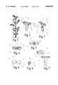
- FIG. 1is a front view of a first presently preferred embodiment of our stake system used to support a plant with a single stake.
- FIG. 2is a perspective view of a present preferred coupling used in our stake system.
- FIG. 3is a sectional view taken along the line III--III of FIG. 2.
- FIG. 4is a top plan view of the coupling shown in FIG. 2.
- FIG. 5is a top plan view similar to FIG. 4 showing a second present preferred embodiment of the coupling.
- FIG. 6is a top plan view similar to FIG. 5 showing a third present preferred embodiment of the coupling.
- FIG. 7is an exploded view of the coupling of FIG. 2 with a present preferred elbow.
- FIG. 8is a front view of a the elbow shown in FIG. 7.
- FIG. 9is a perspective view of a rod holder that can be used with the coupling.
- FIG. 10is a perspective view of our stake system configured to support a plant using three stakes.
- FIG. 11is a front view of our stake system with horizontal rods holding decorative lights.
- FIG. 12is a front view of a present preferred light holder attached to a portion of the rod used in the embodiment of FIG. 10.
- FIG. 13is a perspective view of the light holder shown in FIG. 12.
- FIG. 14is a front view of our stake system configured to create a star lawn ornament.
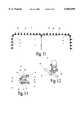
- FIG. 15is a front view of another embodiment of our stake system which includes bendable or preformed frame members assembled into a Santa Claus ornament.
- FIG. 16is a perspective view of a moveable plate type rod holder in an open position.
- FIG. 17is a top plan view of the moveable plate type rod holder shown in FIG. 16, but in a closed position.
- FIG. 18is a top plan view, similar to FIGS. 4-6, of the coupling having bridge portions as shown in FIG. 15.
- FIG. 19is a perspective view of a presently preferred embodiment of a rod having a non-circular cross section.
- FIG. 20is a perspective view similar to FIG. 19 showing another presently preferred embodiment of a rod having grooves.
- FIG. 21is a perspective view similar to FIG. 20 showing a further presently preferred embodiment of a rod having surface deformations.
- our stake system 1is comprised of a coupling shown in FIGS. 2 through 4 and a set of rods connected together with couplings.
- Two rods 3 connected to two couplings 2are shown in FIG. 1. The lowest rod has been driven into the ground next to plant 5.
- a cloth or wire tie 6runs from each coupling to encircle the stem of the plant and hold it in place.
- the rodspreferably are round fiberglass rods 0.25" (7 mm) in diameter.
- the couplinghas a tubular body 8 which is open at its upper end 7 and at its lower end 9.
- An interior wall or collar 12defines upper cavity 10 and lower cavity 11.
- the inner wall 13 of the lower cavity and the inner wall 14 of the upper cavityare tapered to allow easy insertion of a rod 3 and provide a friction fit.
- a collar 19 or other projectionmay be provided on the rod 3 which snaps into groove 25 on the inner surface of the cavity as shown in chain line in FIG. 3.
- the rod and cavitiesmay have a triangular, oval, square, octagonal or other non-circular cross-section to prevent rotation of the coupling relative to the rod.
- each arm 16has an opening 17 and slot 18.
- the slotallows a string, rope or cord 27 shown in chain line in FIG. 4 to pass through the openings 17.
- braces 20for the arms as shown most clearly in FIGS. 2 and 7.
- the couplingmay be alternatively configured so that the arms 16 form an S-shape as shown in FIG. 5 or are flexible as shown in FIG. 6.
- the arms 16have a ball 28 at the distal end which fits into mouth 29.
- the armsfunction as built-in fasteners.
- bridge portions 15may be provided between the arms 16 to give the upper end of the coupling a disc shape. Such a coupling is shown in FIGS. 15 and 18.
- elbows 22which have a split tubular portion 24 sized to fit within the upper cavity 10 of the coupling or the opening 17 defined by the arms 16.
- the elbow 22can also be tapered toward the opening 26 at the opposite end. Opening 26 is sized to receive rod 3.
- the elbow 22is shown to turn 90 degrees, we further prefer to provide 45 degree elbows and 60 degree elbows. It may also be appropriate to provide a flexible elbow which would allow the user to bend the elbow.
- the rod holderhas a U-shaped rod gripping member 72 which defines an opening or mouth 73 into which a rod is inserted.
- the rod gripping memberis flexible and contoured so that the arms 75 will spread apart to permit insertion of the rod.
- a split tubular portion 74is sized to fit within the upper cavity 10 of the coupling or the openings defined by the arms.
- the stake systemcan be configured to have three rods 3 with a coupling atop each rod.
- a string or cord 27runs between the three couplings 2 to surround the plant 5.
- the string 27can be tied to form a loop and then strung through the openings in the arms as shown by dotted lines 27 in FIG. 4.
- FIGS. 11, 12 and 13we provide couplings 2 on a set of rods 3 that have been driven into the ground.
- the horizontal rodscould be the same fiberglass rods as are used for the vertical rods 3, or they could be tubular, particularly vinyl tubing.
- Decorative lights 32are attached to the horizontal rods.
- the light holders 34can be placed anywhere along the length of the rod to accommodate spacing of lights on any chosen string of lights.
- the rodsmay have an oval, square or other out of round cross-section to prevent the lights from turning or twisting. Such a rod is shown in FIG. 19.
- Each light holder 34preferably has a flexible, S-shaped portion 36 which forms a large opening 38 and a small opening 40 that can grip a socket 42 of a decorative light string.
- the large opening 38is sized to hold the standard indoor C-4 size light bulb socket and the larger outdoor decorative light socket.
- the small opening 40is sized to hold a mini light socket.
- the light holder 34preferably has a pair of arms 43 and 44 which form a slot 45 into which the horizontal rod 30 can be inserted.
- the light holder 34may also have an L-shaped rear leg 48 which forms slot 49.
- Rod 30is inserted into the slot 49 and held in place by fin 50.
- the light holding portioncan terminate at dotted line 52 to form a C-shaped, flexible, gripping member that is able to retain all common size lights.
- the light holdercan be provided with nodules 54 which engage the light socket to more securely retain the decorative light.
- the rods 30are shown held only by stakes, one could secure the rods to other structures such as a house, fence or window frame using any type of fastener including the removable fastener disclosed in U.S. Pat. No. D376,756 for suction cups.
- Our stake systemcan be used to create a star shaped lawn ornament 56 shown in FIG. 14.
- the star shapeis formed by connecting five rods 30 together using elbows 58. Those elbows may be at a fixed angle or flexible.
- the staris held by three rods 3 and attached couplings 2 each connected to a rod 30.
- the rodsmay pass through an opening 17 defined by the arms 16 or be held in a rod holder 70.
- Decorative lights(not shown) are then attached to the star shape.
- bendable wire or plastic rods 62that can be connected using sleeve type couplings.
- This materialcan be bent into an infinite variety of shapes to form lawn ornaments.
- bendable wire 62has been shaped to form the outline of a Santa Claus head 60. This form is supported by several rods 3 and 30, elbows 22 and couplings 2. Strings of decorative lights indicated by the dash and dot lines are attached to the frame.
- This holder 80has a base plate 81 with a post 83 extending from its center.
- a top plate 82fits over the base plate 81 with the post 83 passing through a hole 85 in the center of the top plate 82.
- a slotis provided in the top of post 83 for receipt of cam lever 84.
- the lever 84is attached to the post by pivot pin 86. When the handle 87 is moved downward about the pivot pin 86, cam 88 will push the top plate 82 toward the bottom plate 81. This pressure will enable the holder to grip rods 30 between the plates. As can be seen in FIG.
- the rodscan be positioned at any desired angle. If desired, the mating surfaces 89 of the plates may be roughened or have grooves or have a flexible surface such as a foam or soft rubber to increase the surface contact with the rods.
- a mounting post 79extends from the bottom of the base plate and is sized to fit into the openings of the arms or the upper cavity.
- the couplings and elbows and rod holders used in our stake systemcould be made of any metal, wood or plastic which will not break, melt or otherwise deteriorate when used outdoors.
Landscapes
- Engineering & Computer Science (AREA)
- General Engineering & Computer Science (AREA)
- Life Sciences & Earth Sciences (AREA)
- Environmental Sciences (AREA)
- Mutual Connection Of Rods And Tubes (AREA)
Abstract
Description
This invention relates to stakes that can be driven into the ground and used with connectors to support strings of decorative lights or tall garden plants such as tomato plants.
The use of lights for decorating the exterior of a house is well known. Decorative lights typically consist of a large number of light sockets being wired together with light bulbs positioned in the light sockets. The "string" of decorative lights is then attached to the face of a building, to a fence or other structure. U.S. Pat. No. 5,667,174 discloses a plastic stake having an S-shaped light holder. A set of these stakes can hold a string of decorative lights by each S-shaped light holder gripping a light socket. Although this light stake allows the user to display decorative lights in a variety of places, the light string is held along generally straight lines at the same or nearly the same height from the ground. This stake can also be used to support growing plants by positioning the stem in the S-shaped holder or tying the stem to the stake. This use is limited by the height of the stake.
There are presently available a variety of decorations in which a wire or plastic frame is shaped like a recognizable object and decorative lights are attached to the frame. This type of lawn ornament can often be seen during the Christmas season in the form of reindeer, snowmen, Santa Claus and other seasonal shapes. Although many of these decorations are very attractive most of them are large and cannot be easily disassembled for storage. These decorations have pre-formed shapes that cannot be changed by the buyer.
Many people enjoy making Christmas decorations but do not have the time, talent or tools to construct lighted lawn ornaments. Hence, they either purchase pre-formed lawn ornaments, string lights on stakes like the one of U.S. Pat. No. 5,667,174, or do not have any lighted lawn ornaments. Thus, there is a need for a kit containing stakes and other components that would enable a consumer to construct lighted lawn ornaments easily and at a reasonable cost. The ornaments must not be adversely affected by cold temperatures and should be able to hold the lights during high winds which commonly accompany winter storms. The finished ornament should be easy to disassemble for storage after the holidays.
We provide a stake system for decorative lights that allows a person of average mechanical ability to create lighted lawn ornaments in an almost infinite variety of shapes and sizes. The stake system has a set of couplings and fiberglass rods and can be expanded to include bendable wire and light holders which fit onto the rods. The connector has a tubular body open at opposite ends and a transverse inner wall or collar between the opposite ends which with the inner wall of the body defines an open upper cavity and an open lower cavity. Each cavity is sized to receive one end of a rod. A pair of arms extend outwardly from opposite edges of one end of the tubular housing. Each arm has a slotted opening of sufficient diameter to permit a cord of a decorative light string to be inserted into and pass through the opening. Preferably the openings are of the same diameter as the cavities in the body of the coupling. Elbows, U-shaped rod holders, and moveable plate type rod holders are provided which have one end or post that fits into the coupling upper cavity. The elbows and U-shaped rod holders have a cavity or mouth sized to receive one end of a rod. A set of rods, elbows or rod holders and couplings can be connected together along a line or assembled to form a star or other shapes.
We also prefer to provide light holders which snap onto the rods. Each light holder preferably has an S-shaped portion that can grip a socket of a decorative light string. Alternatively, the light holder can be a C-shaped, flexible, gripping member that is able to retain all common size lights. The light holder can be provided with nodules which engage the light to more securely retain the light.
We may also provide bendable plastic or wire forms that are sized to fit into the elbows, upper cavity or opening in the coupling. The user can form a variety of shapes, attach lights to the formed shape and support the shape with the stake system.
Additional details, object and advantages of the invention will become more readily apparent as the following description of certain present preferred embodiments shown in the drawings proceeds.
The drawings show presently preferred embodiments of our stake system in which:
FIG. 1 is a front view of a first presently preferred embodiment of our stake system used to support a plant with a single stake.
FIG. 2 is a perspective view of a present preferred coupling used in our stake system.
FIG. 3 is a sectional view taken along the line III--III of FIG. 2.
FIG. 4 is a top plan view of the coupling shown in FIG. 2.
FIG. 5 is a top plan view similar to FIG. 4 showing a second present preferred embodiment of the coupling.
FIG. 6 is a top plan view similar to FIG. 5 showing a third present preferred embodiment of the coupling.
FIG. 7 is an exploded view of the coupling of FIG. 2 with a present preferred elbow.
FIG. 8 is a front view of a the elbow shown in FIG. 7.
FIG. 9 is a perspective view of a rod holder that can be used with the coupling.
FIG. 10 is a perspective view of our stake system configured to support a plant using three stakes.
FIG. 11 is a front view of our stake system with horizontal rods holding decorative lights.
FIG. 12 is a front view of a present preferred light holder attached to a portion of the rod used in the embodiment of FIG. 10.
FIG. 13 is a perspective view of the light holder shown in FIG. 12.
FIG. 14 is a front view of our stake system configured to create a star lawn ornament.
FIG. 15 is a front view of another embodiment of our stake system which includes bendable or preformed frame members assembled into a Santa Claus ornament.
FIG. 16 is a perspective view of a moveable plate type rod holder in an open position.
FIG. 17 is a top plan view of the moveable plate type rod holder shown in FIG. 16, but in a closed position.
FIG. 18 is a top plan view, similar to FIGS. 4-6, of the coupling having bridge portions as shown in FIG. 15.
FIG. 19 is a perspective view of a presently preferred embodiment of a rod having a non-circular cross section.
FIG. 20 is a perspective view similar to FIG. 19 showing another presently preferred embodiment of a rod having grooves.
FIG. 21 is a perspective view similar to FIG. 20 showing a further presently preferred embodiment of a rod having surface deformations.
Similar reference numerals are used to indicate similar parts in all figures of the drawings.
Referring to FIGS. 1 through 4 ourstake system 1 is comprised of a coupling shown in FIGS. 2 through 4 and a set of rods connected together with couplings. Tworods 3 connected to twocouplings 2 are shown in FIG. 1. The lowest rod has been driven into the ground next toplant 5. A cloth orwire tie 6 runs from each coupling to encircle the stem of the plant and hold it in place. The rods preferably are round fiberglass rods 0.25" (7 mm) in diameter.
As shown in FIGS. 2, 3 and 4, the coupling has atubular body 8 which is open at itsupper end 7 and at itslower end 9. An interior wall orcollar 12 definesupper cavity 10 andlower cavity 11. Theinner wall 13 of the lower cavity and theinner wall 14 of the upper cavity are tapered to allow easy insertion of arod 3 and provide a friction fit. Alternatively, acollar 19 or other projection may be provided on therod 3 which snaps intogroove 25 on the inner surface of the cavity as shown in chain line in FIG. 3. If desired, the rod and cavities may have a triangular, oval, square, octagonal or other non-circular cross-section to prevent rotation of the coupling relative to the rod. At theupper end 7 of the coupling we prefer to provide twoarms 16 which extend outwardly opposite one another. Each arm has anopening 17 andslot 18. The slot allows a string, rope orcord 27 shown in chain line in FIG. 4 to pass through theopenings 17. We further prefer to providebraces 20 for the arms as shown most clearly in FIGS. 2 and 7.
The coupling may be alternatively configured so that thearms 16 form an S-shape as shown in FIG. 5 or are flexible as shown in FIG. 6. In the embodiment of FIG. 6 thearms 16 have aball 28 at the distal end which fits intomouth 29. In this configuration the arms function as built-in fasteners. If desired,bridge portions 15 may be provided between thearms 16 to give the upper end of the coupling a disc shape. Such a coupling is shown in FIGS. 15 and 18.
We further prefer to provideelbows 22 which have a splittubular portion 24 sized to fit within theupper cavity 10 of the coupling or theopening 17 defined by thearms 16. We further prefer to make the elbow to have a 90 degree turn with anopening 26 at its opposite end. Theelbow 22 can also be tapered toward theopening 26 at the opposite end.Opening 26 is sized to receiverod 3. Although theelbow 22 is shown to turn 90 degrees, we further prefer to provide 45 degree elbows and 60 degree elbows. It may also be appropriate to provide a flexible elbow which would allow the user to bend the elbow.
We also prefer to provideU-shaped rod holders 70 like that shown in FIG. 9. The rod holder has a U-shapedrod gripping member 72 which defines an opening ormouth 73 into which a rod is inserted. The rod gripping member is flexible and contoured so that thearms 75 will spread apart to permit insertion of the rod. Asplit tubular portion 74 is sized to fit within theupper cavity 10 of the coupling or the openings defined by the arms.
As can be seen in FIG. 10, the stake system can be configured to have threerods 3 with a coupling atop each rod. A string orcord 27 runs between the threecouplings 2 to surround theplant 5. Thestring 27 can be tied to form a loop and then strung through the openings in the arms as shown by dottedlines 27 in FIG. 4.
Referring to the embodiment of FIGS. 11, 12 and 13 we providecouplings 2 on a set ofrods 3 that have been driven into the ground. We connect ahorizontal rod 30 between each pair of adjacent couplings. The horizontal rods could be the same fiberglass rods as are used for thevertical rods 3, or they could be tubular, particularly vinyl tubing.Decorative lights 32 are attached to the horizontal rods. We also prefer to providelight holders 34 which snap onto therods 30. The light holders can be placed anywhere along the length of the rod to accommodate spacing of lights on any chosen string of lights. The rods may have an oval, square or other out of round cross-section to prevent the lights from turning or twisting. Such a rod is shown in FIG. 19. The rods also could be threaded or have ridges 35grooves 95, orother surface irregularities 97 to prevent or retard the light holders from sliding along the rod. Such rods are shown in FIG. 13, 20 and 21. Eachlight holder 34 preferably has a flexible, S-shapedportion 36 which forms alarge opening 38 and asmall opening 40 that can grip asocket 42 of a decorative light string. Thelarge opening 38 is sized to hold the standard indoor C-4 size light bulb socket and the larger outdoor decorative light socket. Thesmall opening 40 is sized to hold a mini light socket. Thelight holder 34 preferably has a pair ofarms slot 45 into which thehorizontal rod 30 can be inserted. Thelight holder 34 may also have an L-shapedrear leg 48 which formsslot 49.Rod 30 is inserted into theslot 49 and held in place byfin 50. Alternatively, the light holding portion can terminate atdotted line 52 to form a C-shaped, flexible, gripping member that is able to retain all common size lights. The light holder can be provided withnodules 54 which engage the light socket to more securely retain the decorative light. Although therods 30 are shown held only by stakes, one could secure the rods to other structures such as a house, fence or window frame using any type of fastener including the removable fastener disclosed in U.S. Pat. No. D376,756 for suction cups.
Our stake system can be used to create a star shapedlawn ornament 56 shown in FIG. 14. The star shape is formed by connecting fiverods 30 together usingelbows 58. Those elbows may be at a fixed angle or flexible. The star is held by threerods 3 and attachedcouplings 2 each connected to arod 30. The rods may pass through anopening 17 defined by thearms 16 or be held in arod holder 70. We also prefer to tierods 30 together where they overlap using wire ties 59. Decorative lights (not shown) are then attached to the star shape.
We prefer to provide a supply of bendable wire orplastic rods 62 that can be connected using sleeve type couplings. This material can be bent into an infinite variety of shapes to form lawn ornaments. In the embodiment of FIG. 15bendable wire 62 has been shaped to form the outline of aSanta Claus head 60. This form is supported byseveral rods elbows 22 andcouplings 2. Strings of decorative lights indicated by the dash and dot lines are attached to the frame.
For some decorative shapes it may be necessary to have several rods radiating from a central point like the spokes on a wheel. This can be done using the rod holder shown in FIGS. 16 and 17. Thisholder 80 has abase plate 81 with apost 83 extending from its center. Atop plate 82 fits over thebase plate 81 with thepost 83 passing through ahole 85 in the center of thetop plate 82. A slot is provided in the top ofpost 83 for receipt ofcam lever 84. Thelever 84 is attached to the post bypivot pin 86. When thehandle 87 is moved downward about thepivot pin 86, cam 88 will push thetop plate 82 toward thebottom plate 81. This pressure will enable the holder to griprods 30 between the plates. As can be seen in FIG. 17 the rods can be positioned at any desired angle. If desired, the mating surfaces 89 of the plates may be roughened or have grooves or have a flexible surface such as a foam or soft rubber to increase the surface contact with the rods. A mountingpost 79 extends from the bottom of the base plate and is sized to fit into the openings of the arms or the upper cavity.
The couplings and elbows and rod holders used in our stake system could be made of any metal, wood or plastic which will not break, melt or otherwise deteriorate when used outdoors. We prefer to use polypropylene or Lexan brand plastic. These plastics are easy to mold and can provide a clear or frosted appearance.
Although we have shown certain present preferred embodiments of our stake system it should be distinctly understood that our invention is not limited thereto but may be variously embodied within the scope of the following claims.
Claims (17)
1. A connector comprised of:
a. a tubular body open at opposite ends and having a transverse inner wall between the opposite ends so that the tubular body and the inner wall define an open upper cavity and an open lower cavity each cavity sized to releasably receive one end of a rod;
b. a pair of arms extending outwardly from opposite edges of one end of the tubular body, each arm having a slotted opening of sufficient diameter to permit a cord of a decorative light string to be inserted into and pass through the opening; and
c. an elbow having a tubular portion at one end and an open cavity at an opposite end thereof sized to releasably receive one end of a rod, said tubular portion inserted into one of the openings in the arms and the upper cavity.
2. The connector of claim 1 wherein the elbow has an opening in an end opposite the inserted end which opening has a same diameter as the upper cavity.
3. The connector of claim 1 wherein the end of the elbow opposite the inserted end is tapered.
4. A stake system comprised of:
a. a plurality of connectors, each connector having a tubular body open at opposite ends and having a transverse inner wall between the opposite ends so that the tubular body and the inner wall define an open upper cavity and an open lower cavity, each cavity sized to receive one end of a rod, and a pair of arms extending outwardly from opposite edges of one end of the tubular body each arm having a slotted opening of sufficient diameter to permit a cord of a decorative light string to be inserted into and pass through the opening;
b. a plurality of rods each rod having one end inserted into the lower cavity of a respective one of said plurality of connectors;
c. a plurality of elbows each elbow having one end inserted into one of the openings in the arms and the upper cavity of a respective one of said plurality of connectors and having an opening in an opposite end; and
d. a plurality of transverse rods each transverse rod having one end inserted into an opening of a respective one of said plurality of elbows.
5. The stake system of claim 4 wherein the plurality of elbows and traverse rods form a recognizable decorative shape.
6. The stake system of claim 5 wherein the shape is a star.
7. A stake system comprised of
a. a plurality of connectors each connector having a tubular body open at opposite ends and having a transverse inner wall between the opposite ends so that the tubular body and the inner wall define an open upper cavity and an open lower cavity each cavity sized to receive one end of a rod and a pair of arms extending outwardly from opposite edges of one end of the tubular housing each arm having a slotted opening of sufficient diameter to permit a cord of a decorative light string to be inserted into and pass through the opening;
b. a plurality of rods each rod having one end inserted into the lower cavity of a respective one of said plurality of connectors;
c. a plurality of elbows each elbow having one end inserted into one of the openings in the arms and the upper cavity of a respective one of said plurality of connectors and having an opening in an opposite end;
d. a plurality of transverse rods each transverse rod having one end inserted into an opening of a respective one of said plurality of elbows; and
e. a plurality of decorative light holders, each light holder attached to one of said plurality of transverse rods.
8. The stake system of claim 7 also comprising at least one decorative light string held by the plurality of decorative light holders.
9. A stake system comprised of
a. a plurality of connectors, each connector having a tubular body open at opposite ends and having a transverse inner wall between the opposite ends so that the tubular body and the inner wall define an open upper cavity and an open lower cavity each cavity sized to receive one end of a rod and a pair of arms extending outwardly from opposite edges of one end of the tubular body each arm having a slotted opening of sufficient diameter to permit a cord of a decorative light string to be inserted into and pass through the opening;
b. a plurality of rods each rod having one end inserted into the lower cavity of a respective one of said plurality of connectors; and
c. at least one string of decorative lights having a cord which cord passes through the opening of at least one arm of at least one of said plurality of connectors.
10. A stake system comprised of:
a. a plurality of connectors, each connector having a tubular body open at opposite ends and having a transverse inner wall between the opposite ends so that the tubular body and the inner wall define an open upper cavity and an open lower cavity, each cavity sized to receive one end of a rod, and a pair of arms extending outwardly from opposite edges of one end of the tubular body each arm having a slotted opening of sufficient diameter to permit a cord of a decorative light string to be inserted into and pass through the opening;
b. a plurality of rods each rod having one end inserted into the lower cavity of a respective one of said plurality of connectors; and
c. a plurality of rod holders each rod holder having an end inserted into one of the openings in the arms and the upper cavity of a respective one of said plurality of connectors and having a rod gripping portion having an opening into which an end of one of said plurality of rods is inserted.
11. The stake system of claim 10 wherein the rod gripping portion is U-shaped.
12. A stake system comprised of
a. a plurality of connectors, each connector having a tubular body open at opposite ends and having a transverse inner wall between the opposite ends so that the tubular body and the inner wall define an open upper cavity and an open lower cavity each cavity sized to receive one end of a rod and a pair of arms extending outwardly from opposite edges of one end of the tubular body each arm having a slotted opening of sufficient diameter to permit a cord of a decorative light string to be inserted into and pass through the opening;
b. a plurality of rods each rod having one end inserted into the lower cavity of a respective one of said plurality of connectors;
c. a plurality of rod holders each rod holder having an end inserted into one of the openings in the arms and the upper cavity of one of said plurality of connectors and having a rod gripping portion having an opening into which an end of one of said plurality of rods is inserted; and
d. the rod gripping portion is a pair of moveable plates.
13. A system for displaying decorative lights comprised of:
a. a plurality of rods;
b. a plurality of decorative light holders each comprised of:
i. a pair of arms attached at one end and spaced apart at an opposite end to define an opening into which an end of a respective one of said plurality of rods is inserted; and
ii. a light holder attached to the arms and having a flexible S-shaped or C-shaped portion which defines an opening sized to receive and grip a socket of a decorative light string; and
c. a plurality of connectors attached to the plurality of rods, each connector sized and configured for attachment to a support structure, and each connector comprised of:
i. a tubular body open at opposite ends and having a transverse inner wall between the opposite ends so that the tubular body and the inner wall define an open upper cavity and an open lower cavity each cavity sized to releasably receive one end of a rod such that a pair of rods are joined end to end.
14. The system of claim 13 wherein the rods have a non-circular transverse cross-section.
15. The system of claim 13 wherein at least one of the plurality of rods has surface deformations.
16. The system of claim 15 wherein the deformations are threads or grooves.
17. The system of claim 13 wherein the support structure is a plurality of support rods.
Priority Applications (1)
| Application Number | Priority Date | Filing Date | Title |
|---|---|---|---|
| US08/957,947US6065899A (en) | 1997-10-27 | 1997-10-27 | Stake system |
Applications Claiming Priority (1)
| Application Number | Priority Date | Filing Date | Title |
|---|---|---|---|
| US08/957,947US6065899A (en) | 1997-10-27 | 1997-10-27 | Stake system |
Publications (1)
| Publication Number | Publication Date |
|---|---|
| US6065899Atrue US6065899A (en) | 2000-05-23 |
Family
ID=25500382
Family Applications (1)
| Application Number | Title | Priority Date | Filing Date |
|---|---|---|---|
| US08/957,947Expired - LifetimeUS6065899A (en) | 1997-10-27 | 1997-10-27 | Stake system |
Country Status (1)
| Country | Link |
|---|---|
| US (1) | US6065899A (en) |
Cited By (13)
| Publication number | Priority date | Publication date | Assignee | Title |
|---|---|---|---|---|
| US6430891B1 (en) | 2000-09-28 | 2002-08-13 | Adams Mfg. Corp. | Construction element and coupling device thereof |
| US20060042160A1 (en)* | 2004-08-30 | 2006-03-02 | Paul Lipkin | Tomato stake |
| US20100212223A1 (en)* | 2009-02-26 | 2010-08-26 | Lloyd William Gibbons | Plant support with securing ring |
| GB2485582A (en)* | 2010-11-19 | 2012-05-23 | Ian Hulf | A fitment for plant support system |
| US20120285740A1 (en)* | 2011-05-10 | 2012-11-15 | Tyco Electronics Corporation | Cable assembly |
| US20140277151A1 (en)* | 2013-03-15 | 2014-09-18 | DePuy Synthes Products, LLC | Fulcrum Cap for Spinal Constructs |
| US9060470B1 (en)* | 2010-06-30 | 2015-06-23 | Michael Tavis Donaldson | Plant support system |
| US20160353192A1 (en)* | 2015-05-29 | 2016-12-01 | Limitstyle Inc. | Earphone cord managing device |
| US20170172073A1 (en)* | 2015-12-18 | 2017-06-22 | Barend J. Van Den Heever | Supporting clamp apparatus and process |
| US10302110B2 (en) | 2016-03-08 | 2019-05-28 | Alan Lee Johnson | Spring clamp for construction of plant cages and trellises |
| US10912262B2 (en) | 2017-03-16 | 2021-02-09 | Mighty Crop, Llc | Plant support and training system and method of operation thereof |
| US11129340B1 (en)* | 2021-01-12 | 2021-09-28 | Gabriel Pena | Plant training device |
| USD1078536S1 (en)* | 2025-01-03 | 2025-06-10 | Menghua Li | Plant propagation station |
Citations (24)
| Publication number | Priority date | Publication date | Assignee | Title |
|---|---|---|---|---|
| US556194A (en)* | 1896-03-10 | meaher | ||
| US2128005A (en)* | 1937-06-25 | 1938-08-23 | Albert H Tinnerman | Hammer-driven supporting device |
| US2751174A (en)* | 1952-12-19 | 1956-06-19 | Floyd S Parker | Fishing pole holder |
| US3494072A (en)* | 1967-07-10 | 1970-02-10 | Famco Inc | Devices for supporting plants |
| US3541322A (en)* | 1967-05-31 | 1970-11-17 | Roy L Bennett | Supports for light arrangements and the like |
| US3704367A (en)* | 1971-11-12 | 1972-11-28 | Lawrence J Korb | Lighted christmas star display |
| US4048752A (en)* | 1975-11-24 | 1977-09-20 | Howard Anderson | Supports |
| US4194851A (en)* | 1977-11-10 | 1980-03-25 | Polyproducts Corp. | Universal hub for geodesic domes |
| US4677788A (en)* | 1985-10-28 | 1987-07-07 | Frank Mastandrea | Support for tomato plants and the like |
| US4942693A (en)* | 1989-03-24 | 1990-07-24 | Josie Sibold | Plant supporting umbrella |
| US4956757A (en)* | 1989-08-21 | 1990-09-11 | Wang Chern Jen | Lamp device |
| US4991344A (en)* | 1986-07-28 | 1991-02-12 | Carney Raymond M | Apparatus for holding plants, pots or the like |
| US5046882A (en)* | 1989-09-27 | 1991-09-10 | Bae Jin Corporation | Tent frame folding device |
| US5060961A (en)* | 1987-11-18 | 1991-10-29 | Keith Bontrager | Mechanically joined steering assembly |
| US5316245A (en)* | 1991-10-25 | 1994-05-31 | Trw United Carr Gmbh & Co., Kg | Plastic holding element |
| US5340065A (en)* | 1993-07-20 | 1994-08-23 | Thomas John E | Support post |
| US5341593A (en)* | 1993-02-17 | 1994-08-30 | Foreman Howard R | Plant support |
| US5437449A (en)* | 1994-07-29 | 1995-08-01 | Zink; Albert H. | Golf club holder and turf repair tool |
| US5584567A (en)* | 1995-06-07 | 1996-12-17 | Rumpel; Donald | Decorative light mount |
| USD376756S (en) | 1995-12-29 | 1996-12-24 | Adams Mfg. Corp. | Removable fastener |
| US5609415A (en)* | 1995-02-09 | 1997-03-11 | Santa's Best | Light clip for shingles or gutters |
| US5667174A (en)* | 1995-01-13 | 1997-09-16 | Adams Mfg. Corp. | Decorative light stake |
| US5765787A (en)* | 1995-08-28 | 1998-06-16 | Illinois Tool Works Inc. | Aperture held clip type fastener |
| US5876111A (en)* | 1996-09-04 | 1999-03-02 | Wu; Jeng-Shyong | Decorative lighting string with expandable, shrinkable and three-dimensional unit |
- 1997
- 1997-10-27USUS08/957,947patent/US6065899A/ennot_activeExpired - Lifetime
Patent Citations (24)
| Publication number | Priority date | Publication date | Assignee | Title |
|---|---|---|---|---|
| US556194A (en)* | 1896-03-10 | meaher | ||
| US2128005A (en)* | 1937-06-25 | 1938-08-23 | Albert H Tinnerman | Hammer-driven supporting device |
| US2751174A (en)* | 1952-12-19 | 1956-06-19 | Floyd S Parker | Fishing pole holder |
| US3541322A (en)* | 1967-05-31 | 1970-11-17 | Roy L Bennett | Supports for light arrangements and the like |
| US3494072A (en)* | 1967-07-10 | 1970-02-10 | Famco Inc | Devices for supporting plants |
| US3704367A (en)* | 1971-11-12 | 1972-11-28 | Lawrence J Korb | Lighted christmas star display |
| US4048752A (en)* | 1975-11-24 | 1977-09-20 | Howard Anderson | Supports |
| US4194851A (en)* | 1977-11-10 | 1980-03-25 | Polyproducts Corp. | Universal hub for geodesic domes |
| US4677788A (en)* | 1985-10-28 | 1987-07-07 | Frank Mastandrea | Support for tomato plants and the like |
| US4991344A (en)* | 1986-07-28 | 1991-02-12 | Carney Raymond M | Apparatus for holding plants, pots or the like |
| US5060961A (en)* | 1987-11-18 | 1991-10-29 | Keith Bontrager | Mechanically joined steering assembly |
| US4942693A (en)* | 1989-03-24 | 1990-07-24 | Josie Sibold | Plant supporting umbrella |
| US4956757A (en)* | 1989-08-21 | 1990-09-11 | Wang Chern Jen | Lamp device |
| US5046882A (en)* | 1989-09-27 | 1991-09-10 | Bae Jin Corporation | Tent frame folding device |
| US5316245A (en)* | 1991-10-25 | 1994-05-31 | Trw United Carr Gmbh & Co., Kg | Plastic holding element |
| US5341593A (en)* | 1993-02-17 | 1994-08-30 | Foreman Howard R | Plant support |
| US5340065A (en)* | 1993-07-20 | 1994-08-23 | Thomas John E | Support post |
| US5437449A (en)* | 1994-07-29 | 1995-08-01 | Zink; Albert H. | Golf club holder and turf repair tool |
| US5667174A (en)* | 1995-01-13 | 1997-09-16 | Adams Mfg. Corp. | Decorative light stake |
| US5609415A (en)* | 1995-02-09 | 1997-03-11 | Santa's Best | Light clip for shingles or gutters |
| US5584567A (en)* | 1995-06-07 | 1996-12-17 | Rumpel; Donald | Decorative light mount |
| US5765787A (en)* | 1995-08-28 | 1998-06-16 | Illinois Tool Works Inc. | Aperture held clip type fastener |
| USD376756S (en) | 1995-12-29 | 1996-12-24 | Adams Mfg. Corp. | Removable fastener |
| US5876111A (en)* | 1996-09-04 | 1999-03-02 | Wu; Jeng-Shyong | Decorative lighting string with expandable, shrinkable and three-dimensional unit |
Non-Patent Citations (2)
| Title |
|---|
| Adams Mfg. Product Sheet "Large Count Value Packs=Higher Retail Sales," Nov. 1994. |
| Adams Mfg. Product Sheet Large Count Value Packs Higher Retail Sales, Nov. 1994.* |
Cited By (17)
| Publication number | Priority date | Publication date | Assignee | Title |
|---|---|---|---|---|
| US20020178685A1 (en)* | 2000-09-28 | 2002-12-05 | Adams William E. | Construction element and coupling device therefor |
| US6857247B2 (en) | 2000-09-28 | 2005-02-22 | Adams Mfg. Corp. | Construction element and coupling device therefor |
| US6430891B1 (en) | 2000-09-28 | 2002-08-13 | Adams Mfg. Corp. | Construction element and coupling device thereof |
| US20060042160A1 (en)* | 2004-08-30 | 2006-03-02 | Paul Lipkin | Tomato stake |
| US20100212223A1 (en)* | 2009-02-26 | 2010-08-26 | Lloyd William Gibbons | Plant support with securing ring |
| US9060470B1 (en)* | 2010-06-30 | 2015-06-23 | Michael Tavis Donaldson | Plant support system |
| GB2485582A (en)* | 2010-11-19 | 2012-05-23 | Ian Hulf | A fitment for plant support system |
| GB2485582B (en)* | 2010-11-19 | 2014-01-08 | Ian Hulf | Plant support and fittings therefor |
| US20120285740A1 (en)* | 2011-05-10 | 2012-11-15 | Tyco Electronics Corporation | Cable assembly |
| US20140277151A1 (en)* | 2013-03-15 | 2014-09-18 | DePuy Synthes Products, LLC | Fulcrum Cap for Spinal Constructs |
| US9173687B2 (en)* | 2013-03-15 | 2015-11-03 | DePuy Synthes Products, Inc. | Fulcrum cap for spinal constructs |
| US20160353192A1 (en)* | 2015-05-29 | 2016-12-01 | Limitstyle Inc. | Earphone cord managing device |
| US20170172073A1 (en)* | 2015-12-18 | 2017-06-22 | Barend J. Van Den Heever | Supporting clamp apparatus and process |
| US10302110B2 (en) | 2016-03-08 | 2019-05-28 | Alan Lee Johnson | Spring clamp for construction of plant cages and trellises |
| US10912262B2 (en) | 2017-03-16 | 2021-02-09 | Mighty Crop, Llc | Plant support and training system and method of operation thereof |
| US11129340B1 (en)* | 2021-01-12 | 2021-09-28 | Gabriel Pena | Plant training device |
| USD1078536S1 (en)* | 2025-01-03 | 2025-06-10 | Menghua Li | Plant propagation station |
Similar Documents
| Publication | Publication Date | Title |
|---|---|---|
| US5667174A (en) | Decorative light stake | |
| US6065899A (en) | Stake system | |
| US5560975A (en) | Decorating system | |
| US7488018B2 (en) | Method and apparatus for remotely affixing and removing decorative lighting from building gutters | |
| US6027228A (en) | Christmas tree lawn ornament | |
| US8888337B2 (en) | Decorative light clip | |
| US8006947B1 (en) | Spiral/coil wrap stand | |
| US5553905A (en) | Ornament handling apparatus | |
| US10247391B2 (en) | Stake for holding a decorative light | |
| US6615543B1 (en) | Planter | |
| US5848493A (en) | Apparatus for attaching a flower to Christmas tree | |
| US5685635A (en) | Decorative lighting system for indoor and outdoor use | |
| US6439744B1 (en) | Decorative ground lighting stake assembly and system | |
| US5536538A (en) | Artificial christmas tree | |
| US6461018B1 (en) | Decorative ground lighting stake assembly and system | |
| US6203171B1 (en) | Apparatus for creating an ornamental lighting display | |
| US20050072881A1 (en) | Device for hanging decorative fixtures | |
| USD457399S1 (en) | Flexible Christmas tree and indoor plant watering funnel | |
| US20070031635A1 (en) | Decorative ornament | |
| US7320816B2 (en) | Collapsible decorative structure | |
| US6394752B1 (en) | Link structure for rods | |
| US6280803B1 (en) | Simulated Christmas tree light display | |
| US6565057B1 (en) | Gazing globe holder | |
| CN211354827U (en) | Decorative flower stand | |
| US7592053B2 (en) | Ornamental figure construction kit |
Legal Events
| Date | Code | Title | Description |
|---|---|---|---|
| AS | Assignment | Owner name:ADAMS MFG. CORP., PENNSYLVANIA Free format text:ASSIGNMENT OF ASSIGNORS INTEREST;ASSIGNORS:ADAMS, WILLIAM E.;ADAMS, WILLIAM E., IV;REEL/FRAME:008945/0629 Effective date:19971024 | |
| STCF | Information on status: patent grant | Free format text:PATENTED CASE | |
| FPAY | Fee payment | Year of fee payment:4 | |
| FPAY | Fee payment | Year of fee payment:8 | |
| FPAY | Fee payment | Year of fee payment:12 | |
| AS | Assignment | Owner name:UBS AG, LONDON BRANCH, AS AGENT, GREAT BRITAIN Free format text:SECURITY INTEREST;ASSIGNOR:ADAMS MFG. CORP.;REEL/FRAME:047975/0860 Effective date:20181221 | |
| AS | Assignment | Owner name:ADAMS MFG. CORP., PENNSYLVANIA Free format text:RELEASE BY SECURED PARTY;ASSIGNOR:UBS AG, LONDON BRANCH, IN ITS CAPACITY AS SECURITY AGENT FOR THE SECURED PARTIES;REEL/FRAME:071236/0860 Effective date:20250403 |