US6065645A - Double-barreled syringe with detachable locking mixing tip - Google Patents
Double-barreled syringe with detachable locking mixing tipDownload PDFInfo
- Publication number
- US6065645A US6065645AUS09/170,146US17014698AUS6065645AUS 6065645 AUS6065645 AUS 6065645AUS 17014698 AUS17014698 AUS 17014698AUS 6065645 AUS6065645 AUS 6065645A
- Authority
- US
- United States
- Prior art keywords
- neck
- syringe
- locking
- bore
- mating
- Prior art date
- Legal status (The legal status is an assumption and is not a legal conclusion. Google has not performed a legal analysis and makes no representation as to the accuracy of the status listed.)
- Expired - Lifetime
Links
- 230000013011matingEffects0.000claimsdescription118
- 230000000712assemblyEffects0.000claimsdescription68
- 238000000429assemblyMethods0.000claimsdescription68
- 239000011345viscous materialSubstances0.000claimsdescription62
- 230000003068static effectEffects0.000claimsdescription38
- 238000010276constructionMethods0.000claimsdescription26
- 238000005192partitionMethods0.000claimsdescription19
- 239000012530fluidSubstances0.000claimsdescription16
- 238000004891communicationMethods0.000claimsdescription11
- 230000000694effectsEffects0.000claimsdescription10
- 239000000463materialSubstances0.000claimsdescription6
- 230000002708enhancing effectEffects0.000claimsdescription5
- 239000002861polymer materialSubstances0.000claims7
- 239000004743PolypropyleneSubstances0.000description8
- -1polypropylenePolymers0.000description8
- 229920001155polypropylenePolymers0.000description8
- 150000001336alkenesChemical class0.000description6
- 238000007789sealingMethods0.000description6
- 239000000203mixtureSubstances0.000description5
- 238000009472formulationMethods0.000description4
- 239000000499gelSubstances0.000description4
- 238000004519manufacturing processMethods0.000description4
- 238000012986modificationMethods0.000description4
- 230000004048modificationEffects0.000description4
- 238000007792additionMethods0.000description2
- 238000005452bendingMethods0.000description2
- 238000001746injection mouldingMethods0.000description2
- 238000000034methodMethods0.000description2
- 210000003813thumbAnatomy0.000description2
- 230000002087whitening effectEffects0.000description2
- QVGXLLKOCUKJST-UHFFFAOYSA-Natomic oxygenChemical compound[O]QVGXLLKOCUKJST-UHFFFAOYSA-N0.000description1
- 150000001875compoundsChemical class0.000description1
- 239000000470constituentSubstances0.000description1
- 230000000994depressogenic effectEffects0.000description1
- 229920001971elastomerPolymers0.000description1
- 239000000806elastomerSubstances0.000description1
- 210000003811fingerAnatomy0.000description1
- QOSATHPSBFQAML-UHFFFAOYSA-Nhydrogen peroxide;hydrateChemical compoundO.OOQOSATHPSBFQAML-UHFFFAOYSA-N0.000description1
- 238000003780insertionMethods0.000description1
- 230000037431insertionEffects0.000description1
- 239000001301oxygenSubstances0.000description1
- 229910052760oxygenInorganic materials0.000description1
- 239000004848polyfunctional curativeSubstances0.000description1
- 229920006124polyolefin elastomerPolymers0.000description1
- 239000012858resilient materialSubstances0.000description1
- 239000011347resinSubstances0.000description1
- 229920005989resinPolymers0.000description1
Images


Classifications
- B—PERFORMING OPERATIONS; TRANSPORTING
- B05—SPRAYING OR ATOMISING IN GENERAL; APPLYING FLUENT MATERIALS TO SURFACES, IN GENERAL
- B05C—APPARATUS FOR APPLYING FLUENT MATERIALS TO SURFACES, IN GENERAL
- B05C17/00—Hand tools or apparatus using hand held tools, for applying liquids or other fluent materials to, for spreading applied liquids or other fluent materials on, or for partially removing applied liquids or other fluent materials from, surfaces
- B05C17/005—Hand tools or apparatus using hand held tools, for applying liquids or other fluent materials to, for spreading applied liquids or other fluent materials on, or for partially removing applied liquids or other fluent materials from, surfaces for discharging material from a reservoir or container located in or on the hand tool through an outlet orifice by pressure without using surface contacting members like pads or brushes
- B05C17/0052—Accessories therefor
- B—PERFORMING OPERATIONS; TRANSPORTING
- B01—PHYSICAL OR CHEMICAL PROCESSES OR APPARATUS IN GENERAL
- B01F—MIXING, e.g. DISSOLVING, EMULSIFYING OR DISPERSING
- B01F25/00—Flow mixers; Mixers for falling materials, e.g. solid particles
- B01F25/40—Static mixers
- B01F25/42—Static mixers in which the mixing is affected by moving the components jointly in changing directions, e.g. in tubes provided with baffles or obstructions
- B01F25/43—Mixing tubes, e.g. wherein the material is moved in a radial or partly reversed direction
- B01F25/431—Straight mixing tubes with baffles or obstructions that do not cause substantial pressure drop; Baffles therefor
- B01F25/4314—Straight mixing tubes with baffles or obstructions that do not cause substantial pressure drop; Baffles therefor with helical baffles
- B01F25/43141—Straight mixing tubes with baffles or obstructions that do not cause substantial pressure drop; Baffles therefor with helical baffles composed of consecutive sections of helical formed elements
- B—PERFORMING OPERATIONS; TRANSPORTING
- B01—PHYSICAL OR CHEMICAL PROCESSES OR APPARATUS IN GENERAL
- B01F—MIXING, e.g. DISSOLVING, EMULSIFYING OR DISPERSING
- B01F33/00—Other mixers; Mixing plants; Combinations of mixers
- B01F33/50—Movable or transportable mixing devices or plants
- B01F33/501—Movable mixing devices, i.e. readily shifted or displaced from one place to another, e.g. portable during use
- B01F33/5011—Movable mixing devices, i.e. readily shifted or displaced from one place to another, e.g. portable during use portable during use, e.g. hand-held
- B—PERFORMING OPERATIONS; TRANSPORTING
- B05—SPRAYING OR ATOMISING IN GENERAL; APPLYING FLUENT MATERIALS TO SURFACES, IN GENERAL
- B05C—APPARATUS FOR APPLYING FLUENT MATERIALS TO SURFACES, IN GENERAL
- B05C17/00—Hand tools or apparatus using hand held tools, for applying liquids or other fluent materials to, for spreading applied liquids or other fluent materials on, or for partially removing applied liquids or other fluent materials from, surfaces
- B05C17/005—Hand tools or apparatus using hand held tools, for applying liquids or other fluent materials to, for spreading applied liquids or other fluent materials on, or for partially removing applied liquids or other fluent materials from, surfaces for discharging material from a reservoir or container located in or on the hand tool through an outlet orifice by pressure without using surface contacting members like pads or brushes
- B05C17/00503—Details of the outlet element
- B05C17/00506—Means for connecting the outlet element to, or for disconnecting it from, the hand tool or its container
- B—PERFORMING OPERATIONS; TRANSPORTING
- B05—SPRAYING OR ATOMISING IN GENERAL; APPLYING FLUENT MATERIALS TO SURFACES, IN GENERAL
- B05C—APPARATUS FOR APPLYING FLUENT MATERIALS TO SURFACES, IN GENERAL
- B05C17/00—Hand tools or apparatus using hand held tools, for applying liquids or other fluent materials to, for spreading applied liquids or other fluent materials on, or for partially removing applied liquids or other fluent materials from, surfaces
- B05C17/005—Hand tools or apparatus using hand held tools, for applying liquids or other fluent materials to, for spreading applied liquids or other fluent materials on, or for partially removing applied liquids or other fluent materials from, surfaces for discharging material from a reservoir or container located in or on the hand tool through an outlet orifice by pressure without using surface contacting members like pads or brushes
- B05C17/00503—Details of the outlet element
- B05C17/00516—Shape or geometry of the outlet orifice or the outlet element
- B—PERFORMING OPERATIONS; TRANSPORTING
- B05—SPRAYING OR ATOMISING IN GENERAL; APPLYING FLUENT MATERIALS TO SURFACES, IN GENERAL
- B05C—APPARATUS FOR APPLYING FLUENT MATERIALS TO SURFACES, IN GENERAL
- B05C17/00—Hand tools or apparatus using hand held tools, for applying liquids or other fluent materials to, for spreading applied liquids or other fluent materials on, or for partially removing applied liquids or other fluent materials from, surfaces
- B05C17/005—Hand tools or apparatus using hand held tools, for applying liquids or other fluent materials to, for spreading applied liquids or other fluent materials on, or for partially removing applied liquids or other fluent materials from, surfaces for discharging material from a reservoir or container located in or on the hand tool through an outlet orifice by pressure without using surface contacting members like pads or brushes
- B05C17/00553—Hand tools or apparatus using hand held tools, for applying liquids or other fluent materials to, for spreading applied liquids or other fluent materials on, or for partially removing applied liquids or other fluent materials from, surfaces for discharging material from a reservoir or container located in or on the hand tool through an outlet orifice by pressure without using surface contacting members like pads or brushes with means allowing the stock of material to consist of at least two different components
- B—PERFORMING OPERATIONS; TRANSPORTING
- B05—SPRAYING OR ATOMISING IN GENERAL; APPLYING FLUENT MATERIALS TO SURFACES, IN GENERAL
- B05C—APPARATUS FOR APPLYING FLUENT MATERIALS TO SURFACES, IN GENERAL
- B05C17/00—Hand tools or apparatus using hand held tools, for applying liquids or other fluent materials to, for spreading applied liquids or other fluent materials on, or for partially removing applied liquids or other fluent materials from, surfaces
- B05C17/005—Hand tools or apparatus using hand held tools, for applying liquids or other fluent materials to, for spreading applied liquids or other fluent materials on, or for partially removing applied liquids or other fluent materials from, surfaces for discharging material from a reservoir or container located in or on the hand tool through an outlet orifice by pressure without using surface contacting members like pads or brushes
- B05C17/01—Hand tools or apparatus using hand held tools, for applying liquids or other fluent materials to, for spreading applied liquids or other fluent materials on, or for partially removing applied liquids or other fluent materials from, surfaces for discharging material from a reservoir or container located in or on the hand tool through an outlet orifice by pressure without using surface contacting members like pads or brushes with manually mechanically or electrically actuated piston or the like
- B—PERFORMING OPERATIONS; TRANSPORTING
- B65—CONVEYING; PACKING; STORING; HANDLING THIN OR FILAMENTARY MATERIAL
- B65D—CONTAINERS FOR STORAGE OR TRANSPORT OF ARTICLES OR MATERIALS, e.g. BAGS, BARRELS, BOTTLES, BOXES, CANS, CARTONS, CRATES, DRUMS, JARS, TANKS, HOPPERS, FORWARDING CONTAINERS; ACCESSORIES, CLOSURES, OR FITTINGS THEREFOR; PACKAGING ELEMENTS; PACKAGES
- B65D81/00—Containers, packaging elements, or packages, for contents presenting particular transport or storage problems, or adapted to be used for non-packaging purposes after removal of contents
- B65D81/32—Containers, packaging elements, or packages, for contents presenting particular transport or storage problems, or adapted to be used for non-packaging purposes after removal of contents for packaging two or more different materials which must be maintained separate prior to use in admixture
- B65D81/325—Containers having parallel or coaxial compartments, provided with a piston or a movable bottom for discharging contents
- B—PERFORMING OPERATIONS; TRANSPORTING
- B01—PHYSICAL OR CHEMICAL PROCESSES OR APPARATUS IN GENERAL
- B01F—MIXING, e.g. DISSOLVING, EMULSIFYING OR DISPERSING
- B01F2101/00—Mixing characterised by the nature of the mixed materials or by the application field
- B01F2101/2305—Mixers of the two-component package type, i.e. where at least two components are separately stored, and are mixed in the moment of application
- B—PERFORMING OPERATIONS; TRANSPORTING
- B01—PHYSICAL OR CHEMICAL PROCESSES OR APPARATUS IN GENERAL
- B01F—MIXING, e.g. DISSOLVING, EMULSIFYING OR DISPERSING
- B01F23/00—Mixing according to the phases to be mixed, e.g. dispersing or emulsifying
- B01F23/40—Mixing liquids with liquids; Emulsifying
- B01F23/47—Mixing liquids with liquids; Emulsifying involving high-viscosity liquids, e.g. asphalt
- B—PERFORMING OPERATIONS; TRANSPORTING
- B01—PHYSICAL OR CHEMICAL PROCESSES OR APPARATUS IN GENERAL
- B01F—MIXING, e.g. DISSOLVING, EMULSIFYING OR DISPERSING
- B01F25/00—Flow mixers; Mixers for falling materials, e.g. solid particles
- B01F25/40—Static mixers
- B01F25/42—Static mixers in which the mixing is affected by moving the components jointly in changing directions, e.g. in tubes provided with baffles or obstructions
- B01F25/43—Mixing tubes, e.g. wherein the material is moved in a radial or partly reversed direction
- B01F25/431—Straight mixing tubes with baffles or obstructions that do not cause substantial pressure drop; Baffles therefor
- B01F25/43197—Straight mixing tubes with baffles or obstructions that do not cause substantial pressure drop; Baffles therefor characterised by the mounting of the baffles or obstructions
- B01F25/431972—Mounted on an axial support member, e.g. a rod or bar
Definitions
- the present inventionrelates to multiple-barreled devices for mixing together and dispensing viscous substances. More particularly, the invention relates to a double-barreled syringe having a double-barreled plunger of unitary construction for dispensing an admixture formed when two gels stored in the barrels are simultaneously discharged into a mixing tip having a five section static mixing element.
- the tipwhich interlocks with the syringe body, is detachable and may be replaced by a locking closure cap to prevent leakage when the syringe is not in use.
- the locking closure cappreferably has a liner which mitigates undesirable leakage during transport and storage.
- U.S. Pat. No. 4,538,920 to G. E. Drakediscloses a double-barreled syringe for mixing and dispensing a two-component material such as a resin and its hardener. Both a mixing tip and a static mixing element located within the tip bore are flexibly rotationally aligned with the syringe body so that the first blade of the mixing element is generally perpendicular to the plane of contiguity between the two component streams exiting a syringe body outlet.
- the mixing tipis connected to the body by centering the tip inlet over the body outlet while aligning the tip so that it can be pushed between opposed bayonet locking tabs, each having a prong and a stop surface, and then rotating the tip so that opposed ramps on the tip inlet end are wedged between the prongs, and a stop surface proximate to each ramp engages a tab stop surface.
- Another object of the inventionis to provide a device which can be repetitively used to dispense desired amounts of an admixture.
- a further object of the inventionis to provide a device having a storage portion and a mixing-dispensing portion which repetitively can be easily connected and then detached, wherein the storage portion does not leak during storage and transport thereof.
- a still further object of the inventionis to provide a device that is inexpensive to manufacture.
- the present inventionprovides a double-barreled syringe wherein one barrel contains a hydrogen peroxide water-based gel formulation used for teeth whitening, and the other contains a gel formulation including compounds that will accelerate the release of oxygen from the first formulation and consequently increase the reaction rate of the teeth whitening process.
- the syringedispenses an admixture formed when the two formulations are simultaneously discharged into a mixing tip having a static mixing element.
- the tipwhich is in locking connection with the syringe body, is replaced by a locking closure cap to prevent leakage when the syringe is not in use.
- the syringe bodyincludes a double-barrel assembly having juxtaposed first and second barrels having a common length and a generally cylindrical bore of a common diameter. Each barrel is bounded at a discharge end by first and second shoulders, respectively, with each shoulder having a generally planar surface. The surfaces are coplanar and contiguous.
- a generally cylindrical neckextends from and is symmetrically disposed between the shoulders. The neck includes first and second outlet passages. Each barrel at its opposite (plunger) end closely receives a piston within its bore. An arcuately-shaped finger-grip circumscribes the contiguous plunger ends of the barrels.
- the syringe bodyfurther includes a double-plunger assembly having juxtaposed first and second plungers of a common length.
- Each plungerextends at a proximal end in an end-piece rigidly attached to one of the pistons, and is rigidly attached at a distal end to a thumb-rest common to the plungers.
- each plungerhas a seal formed integrally therewith at a distal end thereof.
- the sealpreferably comprises a flare having a wall thickness which is sufficiently thin as to flexibly conform to the bore within which it is contained and thus seal the plunger upon which it is formed with respect to the bore.
- an alignment ringis formed proximate the distal end of each plunger.
- the alignment ringis formed proximal of the seal.
- the alignment ringenhances alignment of the seal with respect to the barrel within which the seal is disposed.
- the alignment ringis coupled comparatively flexibly to the shaft of the plunger and the alignment ring is coupled comparatively rigidly to the seal, so as to allow the combination of the alignment ring and the seal to move together as a unit with respect to the shaft while also causing the alignment ring and the seal to remain comparatively fixed in position with respect to one another. In this manner, the alignment ring and the seal remain aligned with respect to the bore within which they are disposed regardless of bending of the shaft of the plunger which may occur during use.
- the alignment ringis attached to the shaft by a first neck and the seal is attached to the alignment ring by a second neck.
- the first neckhas a smaller diameter than the second neck so as to facilitate movement of the combination of the alignment ring and the seal relative to the shaft, while maintaining desired relative alignment of the alignment ring with respect to the seal.
- the combination of the alignment ring and the sealtends to move as a unit with respect to the shaft (which may bend independently of the alignment ring and the seal).
- the syringe bodyfurther includes a first mating assembly having diametrically opposed first and second detents extending outwardly from the neck, and opposed first and second locking ribs symmetrically disposed with respect to the neck and rigidly attached, respectively, to the first and second shoulders.
- Each ribhas a plurality of generally planar locking faces generally parallel to and at a common predetermined distance from the neighboring shoulder surface.
- the syringefurther includes a generally conical mixing tip having an inlet end and a discharge end and a bore therethrough.
- the borehas a generally cylindrical portion at the inlet end and extends in a conically tapered portion toward the discharge end.
- the cylindrical bore portionis determined by a circumferential surface adapted to closely receive the body neck.
- a four section static mixing elementis closely received and wedged within the bore tapered portion.
- the mixing tiphas at the inlet end a second mating assembly having opposed generally planar, arcuate first and second locking tabs of a common predetermined thickness slightly less than the distance between the rib locking faces of the first mating assembly and the neighboring shoulder. Each tab has at least one edge beveled at a common predetermined angle.
- the tabsare symmetrically disposed with respect to the cylindrical bore portion.
- the bore circumferential surfaceincludes diametrically opposed first and second detent recesses and first and second ramps which are contiguous at a proximal end, respectively, to the recesses.
- a five section static mixing elementis received and wedged within the bore tapered portion. It is believed that the use of a five section static mixing element will provide approximately 50% better mixing than the four section static mixing element. Those skilled in the art will appreciate that additional sections of the static mixing element will provide further enhanced mixing and may therefore be desirable.
- each section of the static mixing elementcomprises a single turn screw.
- Each screwis clocked, i.e., configured so as to be right or left handed, opposite that of each adjacent screw and is oriented, with respect to the leading and trailing edges thereof, at 90% with respect to each adjacent screw.
- the screwsare disposed upon a common shaft. The screws taper in size such that the viscous materials flow through successively smaller screws as the viscous materials are dispensed.
- the first and second mating assembliesare conjoined when the neck is inserted into the cylindrical bore portion in a relative orientation such that each detent contacts a ramp distal end, thereby determining an engaged configuration.
- the assembliesinterlock when the mixing tip is rotated in a first direction until each detent, traversing the ramp and reaching the ramp proximal end, is received within a recess. Concurrently, each tab is closely received between one of the pluralities of rib locking faces and a shoulder.
- the mating assembliesare detachable when the mixing tip is rotated in the opposite direction until the neck and cylindrical bore portion are in the engaged configuration.
- a locking closure capis utilized in place of the mixing tip so as to better mitigate leakage during shipping.
- the locking closure capattaches to the body in the same manner as the mixing tip.
- the locking closure capcomprises a locking closure cap liner formed of a comparatively resilient material which provides an enhanced seal between the locking closure cap and the body.
- the locking closure cap linerpreferably comprises a groove formed therein and configured so as to receive a partition formed within the neck of the body.
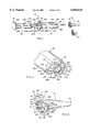
- FIG. 1is an exploded perspective view of a double-barreled syringe according to the invention, including a double-plunger assembly, two pistons, a double-barrel assembly, a static mixing element, a detachable locking mixing tip, and alternatively, a detachable locking cap;
- FIG. 2is a discharge end perspective view of the FIG. 1 double-barrel assembly, including two shoulders, a neck with two outlet passages, and a mating assembly with two diametrically opposed detents and two symmetrically disposed locking ribs for engaging and interlocking with the mixing tip or cap;
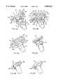
- FIG. 3is an inlet end perspective view of the FIG. 1 mixing tip, including a mating assembly, having two locking tabs, which engages and interlocks with the FIG. 2 mating assembly;
- FIG. 4Ais a combined exploded perspective and partial sectional view of the FIGS. 2 and 3 mating assemblies before engagement;
- FIG. 4Bis a combined perspective and partial sectional view of the FIGS. 2 and 3 mating assemblies after engagement;
- FIG. 4Cis a combined perspective and partial sectional view of the FIGS. 2 and 3 mating assemblies after interlocking;
- FIG. 5Ais a perspective view of the FIGS. 2 and 3 mating assemblies before engagement;
- FIG. 5Bis a perspective view of the FIGS. 2 and 3 mating assemblies after engagement;
- FIG. 5Cis a perspective view of the FIGS. 2 and 3 mating assemblies after interlocking;
- FIG. 6Ais a transverse sectional view of the FIGS. 2 and 3 mating assemblies after engagement;
- FIG. 6Bis a transverse sectional view of the FIGS. 2 and 3 mating assemblies after interlocking;
- FIG. 6Cis a cross-sectional view of the FIG. 6B mating assemblies taken along offset line 6C--6C, showing each locking tab disposed within a recess determined by a FIG. 2 shoulder and locking rib;
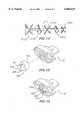
- FIG. 7is a horizontal cross-sectional view of the FIG. 2 discharge end and FIG. 3 inlet end when the mixing tip is locked to the double-barrel assembly;
- FIG. 8is a cross-sectional view orthogonal to FIG. 7;
- FIG. 9is a perspective view of a unitary double-barreled plunger having integrally formed seals at the distal ends thereof;
- FIG. 10is an enlarged side view of one of the distal ends of the double-barreled plunger of FIG. 9, showing the seal;
- FIG. 11is a cross sectional perspective view of the distal end of the plunger of FIG. 10;
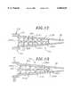
- FIG. 12is a horizontal cross-sectional view of an alternative configuration of the mixing tip, wherein a five element mixer is used instead of the four element mixer of FIGS. 7 and 8;
- FIG. 13is a cross-sectional view orthogonal to FIG. 12;
- FIG. 14is an enlarged side view of the five section mixing element of FIGS. 12 and 13;
- FIG. 15is a perspective view of a locking closure cap showing the locking closure cap liner thereof exploded therefrom;
- FIG. 16is an enlarged perspective view of the locking closure cap of FIG. 15, showing the locking closure cap liner installed therein;
- FIG. 17is a discharge end perspective view of the double-barrel assembly, including two shoulders, a neck with two outlet passages separated by a straight partition, and a mating assembly with two diametrically opposed detents and two symmetrically disposed locking ribs for engaging and interlocking with the mixing tip or cap.
- the inventionrelates to an article of manufacture which is primarily intended for storing and dispensing gels which are components of an admixture and which need to be kept separate until the admixture is formed.
- the inventionis not limited to particular types of material to be stored and dispensed, and can be used for storing and dispensing any material that can be placed within a syringe barrel and effectively admixed by a static mixing tip.
- the word “attached”means that the two parts referred to (e.g., a locking rib and a shoulder or a plunger end-piece and a piston) are either molded in a single piece, or are glued or force-fitted together. However, other forms of attachment may be suitable, consistent with simplicity of manufacture and reliability of operation.
- the word “connected”means that the two parts referred to (viz., the two mating assemblies) can be easily separated after being joined together in an interlocking combination.
- a syringe body 10includes a double-barrel assembly 12 having juxtaposed first and second generally cylindrical barrels 14L, 14R having a common length and a generally cylindrical bore 16L, 16R, respectively, of a common diameter determining storage compartments 15L (not shown), 15R (not shown).
- Barrels 14L, 14Rare bounded at a first (discharge) end 18L, 18R, respectively, by first and second shoulders 20L, 20R, respectively.
- the shouldershave generally planar surfaces 21L, 21R, respectively, which are coplanar and contiguous.
- a generally cylindrical neck 22extends from and is symmetrically disposed between the shoulders. As shown in FIG.
- neck 22includes first and second outlet passages 24L, 24R, divided by a partition 26. As best shown in FIG. 7, passages 24L, 24R are in fluid communication, respectively, with barrels 14L, 14R. Barrels 14L, 14R are open at an opposite (plunger) end 28L, 28R, respectively, which closely receives a piston 30L, 30R, respectively. Barrel ends 28L, 28R are circumscribed by and rigidly attached to an arcuately-shaped finger-grip 32.
- the syringe body 10further includes a double-plunger assembly 36 having juxtaposed generally cylindrical first and second plungers 38L, 38R of a common length.
- Each plungerextends at an end 40L, 40R proximal to a piston in an end-piece 42L, 42R rigidly attached to the piston 30L, 30R, respectively.
- the plungersare attached at their distal end 44L, 44R to a disc-shaped thumb-rest 46 so that when the thumb-rest is depressed the plungers move forward in tandem, and the attached pistons move in tandem within the barrels.
- syringe body 10further includes a first mating assembly 50 having diametrically opposed first and second detents 52, 54 extending outwardly from neck 22, and opposed first and second locking ribs 56L, 56R symmetrically disposed with respect to neck 22.
- Ribs 56L, 56Reach have a first (stand-off) portion 57L, 57R, respectively, generally parallel to the shoulders 20L, 20R, respectively, and generally orthogonal to a second (bracket) portion 58L, 58R (not shown), respectively, rigidly attached, respectively, to shoulders 20L, 20R.
- Rib stand-off portions 57L, 57Reach have two generally planar locking faces 59L, 60L, and 59R (not shown), 60R (not shown), respectively, which are generally parallel to and at a common distance from the neighboring shoulder surface 21L, 21R, respectively, thus determining symmetrical recesses 62L, 62R (not shown), respectively.
- double-barrel assembly 12, including neck 22, and mating assembly 50are fabricated as a unit from a polymerized alkene such as polypropylene by means of an injection molding process.
- a generally conical mixing tip 70includes an inlet end 72 and a discharge end 74 and a bore 76 therethrough.
- bore 76has a generally cylindrical portion 78 proximate to inlet end 72 and extends in a conically tapered portion 80 (not shown) toward the discharge end 74.
- Cylindrical bore portion 78is determined by a circumferential surface 78S adapted to closely receive the neck 22.
- a static mixing element 82is closely received and wedged within the tapered bore portion 80.
- the static mixing element 82comprises a four section static mixing element. That is, the mixing element 82 is comprised of four separate single turn screws.
- Mixing element 82is inserted in a random azimuthal orientation within bore portion 80 and so is not disposed in a predetermined orientation with respect to partition 26 and outlet passages 24L, 24R when mixing tip 70 is attached to double-barrel assembly 12. As further shown in FIGS. 7 and 8, when tip 70 and assembly 12 are attached, proximate end 82P of mixing element 82 and neck 22 are separated by a gap 83.
- Mixing tip 70further includes an indented surface portion 84 to facilitate a person holding the tip between the thumb and fingers to rotate the tip.
- the inlet end 72 of mixing tip 70includes a second mating assembly 90 having opposed generally planar arcuately-shaped first and second locking tabs 92, 94 of a common predetermined thickness slightly less than the common width of recesses 62L, 62R.
- Tabs 92, 94are symmetrically disposed with respect to cylindrical bore portion 78 and have edges 93A (not shown), 93B (not shown) and 95A, 95B, respectively, which are each beveled at an angle of about 8 degrees.
- Tabs 92, 94are rigidly attached, respectively, to structural ribs 98, 100 disposed symmetrically with respect to bore portion 78, and extending in generally oval-shaped collar portions 102, 104, respectively.
- the two collar portionspartially circumscribe inlet end 72 and extend so that tab 92 is rigidly attached at an interior edge 92E (not shown) to collar portion 104, and tab 94 is rigidly attached at an interior edge 94E to collar portion 102.
- Surface 78Sincludes diametrically opposed first and second detent recesses 110, 112 and a plurality of corrugations 114. As shown in FIGS. 4A, 4B, 6A and 6B, recesses 110, 112 are each contiguous to first and second ramps 116, 118, respectively, which are generally planar sloping portions of the surface 78S. As shown in FIGS.
- each detent 52, 54contacts a ramp 116, 118, respectively, at a ramp end 120, 122, respectively, distal to recess 110, 112, respectively.
- mixing tip 70 and associated mating assembly 90are fabricated as a unit from a polymerized alkene such as polypropylene by means of an injection molding process.
- mixing tip 70may be replaced by a closure cap 130 having a mating assembly identical to mating assembly 90 so that cap 130 is interchangeable with mixing tip 70.
- FIGS. 4A and 5Ashow the proper relative orientation between mating assemblies 50 and 90 so that neck 22 can be inserted into bore portion 78.
- FIGS. 4B and 6Ashow the mating assemblies engaged but not yet interlocked.
- FIG. 5Bshows the disposition in the engaged position of collar portion 102 with respect to locking ribs 56L, 56R of mating assembly 50.
- arrows 120, 121show the (counterclockwise) rotational direction for interlocking.
- FIGS. 4A and 4Bshow rib stand-off portions 57L and 57R with respective locking faces 59L, 60L and 59R, 60R.
- FIGS. 4B and 6Afurther show the respective disposition of locking tabs 92, 94 of mating assembly 90 and rib stand-off portions 57L, 57R of mating assembly 50 before interlocking.
- FIGS. 4C and 6Bshow the respective disposition of locking tabs 92, 94 and rib stand-off portions 57L, 57R after interlocking when tabs 92, 94 have been closely received within recesses 62L, 62R, respectively, and detents 52, 54 received within recesses 110, 112, respectively.
- Tab insertion and removalare facilitate by beveled edges 93A, 93B of tab 92 and beveled edges 95A, 95B of tab 94.
- FIG. 5Cshows the disposition in the interlocked position of collar portion 102 with respect to locking ribs 56L, 56R.
- FIGS. 6 and 7show locking tabs 92, 94 received within recesses 62L 62R, respectively, determined, respectively, by shoulders 20L, 20R and rib stand-off portions 57L, 57R with locking faces 59L, 60L and 59R, 60R.
- locking tabs 92, 94when received within recesses 62L, 62R, contact locking faces 59L, 60L and 59R, 60R, respectively.
- FIG. 8shows detents 52, 54 in relation, respectively, to recesses 110, 112 and to collar portions 102, 104.
- a userAfter dispensing a desired amount of admixture, a user typically would detach the mixing tip 70 from the double-barrel assembly 12 by rotating the tip clockwise until detents 52, 54 reach ramp distal ends 120, 122, at which position locking tabs 92, 94 are disengaged from recesses 62L, 62R, and then pulling apart the mixing tip and double-barrel assembly.
- the corrugation in surface 78S contiguous to each ramp distal endacts as a stop for the detent, thus preventing over-rotation and ensuring that mating assemblies 50 and 90 return to the engaged position.
- the closure cap 130may then be connected to the syringe body 10 by using the same engagement and locking procedure as used for the tip.
- the double-barrel assembly 12 and attached mating assembly 50, double-plunger assembly 36, mixing tip 70 and attached mating assembly 90, and closure cap 130are fabricated from a polymerized alkene such as polypropylene.
- the length between thumb-rest 46 and discharge end 74 of mixing tip 70is about 6.75 inches when plungers 38L, 38R are fully retracted.
- the combined width of juxtaposed barrels 14L, 14Ris about 0.65 inch.
- the plungeralternatively comprises a unitary construction double-barreled plunger 336 having sealing tips 200L and 200R formed integrally with shafts 210L and 210R of the plungers 338L and 338R thereof.
- the need for separate sealing tipssuch as those of pistons 30L and 30R of FIG. 1, is eliminated.
- both the materials and assembly costs associated with the plunger assembly 336are reduced.
- the right sealing tip 200Rcomprises a shaft 210R having a first neck 212 attaching the shaft to 210R to an alignment ring 204 and a second neck 208 attaching the alignment ring 204 to a seal 202R.
- a first neck 212attaching the shaft to 210R to an alignment ring 204
- a second neck 208attaching the alignment ring 204 to a seal 202R.
- the shaft 210Rhas a diameter, Dimension A, which is substantially greater than a diameter, Dimension B, of the first neck 212.
- the diameter of the shaft 210R, Dimension Ais somewhat less than the diameter of the cylindrical bore 16R (FIG. 1) within which the shaft 210R is disposed, so as to facilitate easy movement of the shaft 210R within the cylindrical bore 16R.
- the alignment ring 204comprises a first portion 214 having a diameter, Dimension C, which is approximately equal to the diameter, Dimension A, of the shaft 210R.
- the alignment ring 204also has a second portion 216 which has a diameter, Dimension D, which is greater than the diameter, Dimension C, of the first portion 204 thereof.
- the diameter, Dimension D, of the second portion 216 of the alignment ring 204is approximately equal to the diameter of the cylindrical bore 16R within which the plunger 338R is slidably disposed, so as to provide a close fit therewith.
- the second portion 216preferably defines a radiused or rounded surface where it contacts the cylindrical bore 16R.
- Second neck 208has a diameter, Dimension E, which is less than the diameter, Dimension C, of the first portion 214 of the alignment ring 204 and which is greater than the diameter, Dimension B, of the first neck 212.
- the seal 202Rhas a first portion 220 which has a diameter, Dimension F, which is approximately equal to the diameter, Dimension D, of the second portion 216 of the alignment ring 204 (and which is thus approximately equal to the diameter of the cylindrical bore 16R).
- the seal 202Ralso has a second portion 206 which has a diameter, Dimension G, which is substantially greater than the diameter, Dimension F, of the first section 220 of the seal 202R.
- the second section 206 of the seal 202Ris defined by a flare which is comprised of a relatively thin, and consequently comparatively flexible, portion of the seal 202R, and which therefore conforms generally in diameter to the cylindrical bore 16R. In this manner, the second portion 206 of the seal 202R provides a seal between the plunger 38Y and the first bore 16R within which the plunger 338R is disposed.
- the alignment ring 204functions so as to maintain desired alignment of the seal 202R with respect to the cylindrical bore 16R, particularly during use, e.g., dispensing of fluid, of the syringe.
- the shaft 210Rtends to flex or bow as the thumb rest 46 is pushed so as to force viscous material from the cylindrical bore 16R.
- the alignment ring 204mitigates misalignment of the seal 202R and consequent undesirable leakage of viscous material thereby.
- the alignment ring 204in combination with the neck 208 and the seal 202R, define a spool-like member which is substantially more resistant to misalignment within the cylindrical bore 16L than is the seal 202R alone.
- the first neck 212which has a substantially smaller diameter, Dimension B, than the diameter, Dimension E, of the second neck 208, permits some desired movement of the shaft 210R of the plunger 338R, with respect to the combination of the alignment ring 204 and the seal 202R (which are rigidly attached to one another) such that bending of the shaft 210R does not effect substantial misalignment of the seal 202R.
- the diameter, Dimension C, of the first section 214 of the alignment ring 204is substantially less than the diameter of the cylindrical bore 16R, and the second section 216 of the alignment ring 204 has a diameter, Dimension D, approximately equal to that of the diameter of the cylindrical bore 16R, so as to provide a desired amount of friction between the alignment ring 204 and the cylindrical bore 16R.
- the radiused or rounded contact surface of the second section 216also contributes to providing the desired amount of friction between the alignment ring 204 and the cylindrical bore 16R.
- Dimension Ais approximately 0.241 inch
- Dimension Bis approximately 0.129 inch
- Dimension Cis approximately 0.238 inch
- Dimension Dis approximately 0.250 inch
- Dimension Eis approximately 0.165
- Dimension Fis approximately 0.250 inch
- Dimension G.is approximately 0.260 inch.
- the unitary construction double-barreled plunger 336is preferably fabricated from a polymerized alkene such as polypropylene.
- the mixing tip 70Aalternatively comprises a five section static mixing element 82A.
- the five section static mixing element 82Acomprises first 240A, second 240B, third 240C, fourth 240D and fifth 240E sections.
- Each section 240A-240E of the static mixing element 82Apreferably comprises a single turn screw formed upon a common shaft 242 (best shown in FIG. 14) such that each section has a different clock sense, i.e., rotates in a different direction, from each adjacent section. That is, if the screw of a given section 240A-240E is clockwise, then any immediately adjacent section(s) will have a counter clockwise sense.
- each screwis oriented at approximately 90 degrees with respect to the trailing edge of each preceding screw, such that as fluid flows from one screw to another, the fluid is cut approximately in half, so as to effect desired mixing thereof.
- the five section static mixing element 82Ais preferably fabricated from a polymerized alkene such as polypropylene.
- a locking closure cap 130preferably comprises a locking closure cap liner 260 for enhancing the seal between the locking closure cap 130 and the neck 22 so as to prevent undesirable leakage of fluids from the first 14L and second 14R cylindrical barrels.
- the locking closure cap liner 260comprises a base 262 and two outwardly extending protrusions 264 and 266 which define a groove 268 therebetween.
- the groove 268is configured so as to receive a generally planar partition 26A of the neck 22, as shown in FIG. 17.
- the two protrusionsfit tightly within the two outlet passages 24L and 24R so as to effect desired sealing thereof.
- the base 262provides further sealing as it is compressed against the neck 22 by the locking closure cap 130.
- the base 262 of the locking closure cap 130is preferably compressed by approximately 0.008 inch when the locking closure cap 130 is attached to the syringe body 10.
- the locking closure lineris preferably fabricated from polyolefin elastomer, preferably ENGAGE 8401 (ENGAGE is a federally registered trademark of Dupont Dow Elastomers).
- the locking closure capis preferably fabricated form a polymerized alkene, such as polypropylene.
- the locking closure cap liner 260is preferably installed within the locking closure cap by inserting the two outwardly extending protrusions 264 and 266 into the neck 22 such that the partition 26A is received within the locking closure cap liner 260. Then, the locking closure cap 130 is attached to the syringe body 10 in the same manner that the mixing tip 70 is attached thereto. The partition 26A prevents rotation of the locking closure cap liner 260 as the locking closure cap 130 is rotated into the individual position thereof.
- All of the polypropylene components of the present inventionare preferably comprised of Polymerland 3320 AP polypropylene.
- the exemplary double-barreled syringe described herein and shown in the drawingsrepresents only a presently preferred embodiment of the invention. Indeed, various modifications and additions may be made to such embodiment without departing from the spirit and scope of the invention.
- the unitary construction plungermay alternatively comprise a plurality of alignment rings.
- various different configurations of the locking closure cap linerare contemplated.
- various numbers and configurations of the individual sections of the static mixing elementare contemplated.
Landscapes
- Engineering & Computer Science (AREA)
- Mechanical Engineering (AREA)
- Chemical & Material Sciences (AREA)
- Chemical Kinetics & Catalysis (AREA)
- Dispersion Chemistry (AREA)
- Physics & Mathematics (AREA)
- Geometry (AREA)
- Package Specialized In Special Use (AREA)
- Coating Apparatus (AREA)
- Dental Tools And Instruments Or Auxiliary Dental Instruments (AREA)
- Infusion, Injection, And Reservoir Apparatuses (AREA)
Abstract
Description
Claims (65)
Priority Applications (6)
| Application Number | Priority Date | Filing Date | Title |
|---|---|---|---|
| US09/170,146US6065645A (en) | 1997-04-01 | 1998-10-12 | Double-barreled syringe with detachable locking mixing tip |
| CA002311815ACA2311815C (en) | 1998-10-12 | 1999-10-12 | Double-barreled syringe with detachable locking mixing tip |
| AU13125/00AAU1312500A (en) | 1998-10-12 | 1999-10-12 | Double-barreled syringe with detachable locking mixing tip |
| EP99956529AEP1554181A4 (en) | 1998-10-12 | 1999-10-12 | Double-barreled syringe with detachable locking mixing tip |
| PCT/US1999/023604WO2000021842A2 (en) | 1998-10-12 | 1999-10-12 | Double-barreled syringe with detachable locking mixing tip |
| JP2000575762AJP4405678B2 (en) | 1998-10-12 | 1999-10-12 | A twin-barreled syringe with a separable fixed mixing tip |
Applications Claiming Priority (2)
| Application Number | Priority Date | Filing Date | Title |
|---|---|---|---|
| US08/829,944US5819988A (en) | 1997-04-01 | 1997-04-01 | Double-barreled syringe with detachable locking mixing tip |
| US09/170,146US6065645A (en) | 1997-04-01 | 1998-10-12 | Double-barreled syringe with detachable locking mixing tip |
Related Parent Applications (1)
| Application Number | Title | Priority Date | Filing Date |
|---|---|---|---|
| US08/829,944Continuation-In-PartUS5819988A (en) | 1997-04-01 | 1997-04-01 | Double-barreled syringe with detachable locking mixing tip |
Publications (1)
| Publication Number | Publication Date |
|---|---|
| US6065645Atrue US6065645A (en) | 2000-05-23 |
Family
ID=22618742
Family Applications (1)
| Application Number | Title | Priority Date | Filing Date |
|---|---|---|---|
| US09/170,146Expired - LifetimeUS6065645A (en) | 1997-04-01 | 1998-10-12 | Double-barreled syringe with detachable locking mixing tip |
Country Status (6)
| Country | Link |
|---|---|
| US (1) | US6065645A (en) |
| EP (1) | EP1554181A4 (en) |
| JP (1) | JP4405678B2 (en) |
| AU (1) | AU1312500A (en) |
| CA (1) | CA2311815C (en) |
| WO (1) | WO2000021842A2 (en) |
Cited By (57)
| Publication number | Priority date | Publication date | Assignee | Title |
|---|---|---|---|---|
| US6311871B1 (en)* | 1998-11-04 | 2001-11-06 | Kress-Elektrik Gmbh & Co. | Device for pressing out and dispensing dosed quantities of flowable multiple-component compounds |
| US6328182B1 (en)* | 1999-07-23 | 2001-12-11 | Sulzer Chemtech Ag | Two-component cartridge |
| US6394314B1 (en)* | 1999-10-12 | 2002-05-28 | Discus Dental Impressions, Inc. | Double-barreled syringe with detachable locking mixing tip |
| US6503485B1 (en)* | 2001-08-06 | 2003-01-07 | Ultradent Products, Inc. | Two-part dental bleaching systems having improved gel stability and methods for bleaching teeth using such systems |
| US20030069537A1 (en)* | 2001-10-05 | 2003-04-10 | Richard Spero | Laparoscopic spray device and method of use |
| WO2003041605A1 (en)* | 2001-11-16 | 2003-05-22 | 3M Espe Ag | Device for storing, mixing and dispensing a free-flowing material |
| US20030108511A1 (en)* | 1998-08-14 | 2003-06-12 | Sawhney Amarpreet S. | Adhesion barriers applicable by minimally invasive surgery and methods of use thereof |
| US6612465B2 (en) | 2000-10-13 | 2003-09-02 | Dentsply Research & Development Corp. | Multi-component mixing storage and dispensing device |
| US6629774B1 (en)* | 1999-08-11 | 2003-10-07 | Tah Industries, Inc. | Static mixer nozzle and attachment accessory configuration |
| US6632199B1 (en)* | 2000-05-23 | 2003-10-14 | Becton Dickinson And Company | Syringe assembly including plastic tip cap |
| US6689148B2 (en) | 1998-08-14 | 2004-02-10 | Incept Llc | Methods and apparatus for intraluminal deposition of hydrogels |
| US20040144801A1 (en)* | 2000-09-21 | 2004-07-29 | Pierson Paul Richard | Mixing tip for dental materials |
| US6884232B1 (en) | 2003-10-31 | 2005-04-26 | Baxter International Inc. | Laparoscopic spray device and method of use |
| US20050228396A1 (en)* | 2002-06-03 | 2005-10-13 | Soren Jonsson | Feeding device for a monomer |
| US20050226819A1 (en)* | 2002-09-27 | 2005-10-13 | Pierson Paul R | Packaged dental composition |
| US20050255425A1 (en)* | 2000-09-21 | 2005-11-17 | Pierson Paul R | Mixing tip for dental materials |
| US6986883B2 (en)* | 1999-09-09 | 2006-01-17 | Discus Dental, Inc. | Increased peroxide content tooth bleaching gel |
| US20060099156A1 (en)* | 2004-11-09 | 2006-05-11 | Discus Dental Impressions, Inc | Dental whitening compositions |
| US20060189944A1 (en)* | 2005-02-08 | 2006-08-24 | Campbell Patrick K | Spray for fluent materials |
| US20060224175A1 (en)* | 2005-03-29 | 2006-10-05 | Vrba Anthony C | Methods and apparatuses for disposition of a medical device onto an elongate medical device |
| US20060272108A1 (en)* | 2005-06-06 | 2006-12-07 | Ruth Stern | Method to apply a hair care preparation and kit for same |
| US20070086963A1 (en)* | 2005-06-06 | 2007-04-19 | Colour Revolution Inc. | Apparatus to apply a hair care preparation |
| US20070100349A1 (en)* | 2005-10-27 | 2007-05-03 | O'neil Michael | Nucleus augmentation delivery device and technique |
| US20070248567A1 (en)* | 2006-04-24 | 2007-10-25 | Pathak Chandrashekhar P | Protein crosslinkers, crosslinking methods and applications thereof |
| US20070284400A1 (en)* | 2006-06-09 | 2007-12-13 | Paul Richard Pierson | Package for a dental material |
| US20080050408A1 (en)* | 2004-11-26 | 2008-02-28 | Discus Dental, Llc | Dental Whitening Compositions |
| US20080057470A1 (en)* | 2002-12-12 | 2008-03-06 | Discus Dental, Llc | Dental tool having a hand grip |
| US20080114092A1 (en)* | 1998-12-04 | 2008-05-15 | Incept Llc | Adhesion barriers applicable by minimally invasive surgery and methods of use thereof |
| US20080114723A1 (en)* | 1997-07-15 | 2008-05-15 | At&T Corp. | Interaction modalities for multimedia delivery and presentation |
| WO2008154092A1 (en)* | 2007-06-08 | 2008-12-18 | Affinergy, Inc. | Devices for mixing and applying a fluid composition |
| US20090152300A1 (en)* | 2007-12-14 | 2009-06-18 | Discus Dental, Llc | Multi-Compartment Devices Having Dispensing Tips |
| US20090266918A1 (en)* | 2008-04-25 | 2009-10-29 | Jason Fortier | Silicone spray tip |
| US20100065660A1 (en)* | 2008-09-12 | 2010-03-18 | Les Hull | Spray applicator |
| US20100288297A1 (en)* | 2009-05-14 | 2010-11-18 | Ruth Stern | Applicator |
| US7858880B2 (en) | 2006-10-30 | 2010-12-28 | Omron Corporation | Conductive terminal welding method and conductive terminal structure |
| US20110056985A1 (en)* | 2007-09-19 | 2011-03-10 | Kettenbach Gmbh & Co. Kg | Container |
| US20110139821A1 (en)* | 2008-09-22 | 2011-06-16 | Medmix Systems Ag | Connector having mixing element for discharge arrangement |
| US7998106B2 (en) | 2004-05-03 | 2011-08-16 | Thorne Jr Gale H | Safety dispensing system for hazardous substances |
| US20120016319A1 (en)* | 2010-07-16 | 2012-01-19 | Christian Javier Zino Gutierrez | Substance dispenser, especially for medical or cosmetic treatment |
| US8408480B2 (en) | 2008-04-25 | 2013-04-02 | Confluent Surgical, Inc. | Self-cleaning spray tip |
| US20130265846A1 (en)* | 2010-10-26 | 2013-10-10 | Alexander Bublewitz | Double Cartridge, Mixer Therefor and Combination of Double Cartridge and Mixer |
| US20130277393A1 (en)* | 2010-12-24 | 2013-10-24 | Sika Technology Ag | Application device for multi-component substances, a cartridge set and a packaging unit |
| US20140117046A1 (en)* | 2011-10-17 | 2014-05-01 | Sulzer Mixpac Ag | Cartridge, method of manufacturing same and multicomponent cartridge |
| KR101477332B1 (en)* | 2011-08-10 | 2014-12-29 | 필립 풍-아이 호 | Device for mixing and discharging plural materials |
| EP2824111A2 (en) | 2010-04-30 | 2015-01-14 | Alexion Pharmaceuticals, Inc. | Anti-C5A Antibodies and Methods for Using the Antibodies |
| WO2015038818A2 (en) | 2013-09-11 | 2015-03-19 | Arsia Therapeutics, Inc. | Liquid protein formulations containing viscosity-lowering agents |
| WO2015167857A1 (en)* | 2014-04-28 | 2015-11-05 | The Smart Block, L.L.C. | Bovine hoofblock with improved glue application, adhesion, and design |
| US9289922B2 (en) | 2006-11-14 | 2016-03-22 | Atomic Energy Of Canada Limited/Energie | Device and method for surface replication |
| WO2016054259A1 (en) | 2014-10-01 | 2016-04-07 | Arsia Therapeutics, Inc. | Polysaccharide and nucleic acid formulations containing viscosity-lowering agents |
| USD757509S1 (en)* | 2014-09-23 | 2016-05-31 | Sika Technology Ag | Adapter |
| US20180153645A1 (en)* | 2015-06-17 | 2018-06-07 | 3M Innovative Properties Company | A system comprising a static mixer and a dispensing device for dental materials |
| US10309430B2 (en) | 2012-08-10 | 2019-06-04 | Confluent Surgical, Inc. | Pneumatic actuation assembly |
| CN110773379A (en)* | 2018-07-26 | 2020-02-11 | 诺信公司 | Dispensing Tubes for Dispensing Liquid Materials |
| US10562064B2 (en)* | 2014-09-23 | 2020-02-18 | Sika Technology Ag | Head plate device, storage container device, cartridge arrangement, dispensing apparatus, and their usage |
| US10952709B2 (en) | 2014-04-04 | 2021-03-23 | Hyperbranch Medical Technology, Inc. | Extended tip spray applicator for two-component surgical sealant, and methods of use thereof |
| US11395643B2 (en)* | 2016-05-05 | 2022-07-26 | Advanced Medical Solutions Limited | Liquid applicator |
| US20220401897A1 (en)* | 2019-11-08 | 2022-12-22 | Freezio Ag | Method and Device for Producing a Carbonated Beverage |
Families Citing this family (10)
| Publication number | Priority date | Publication date | Assignee | Title |
|---|---|---|---|---|
| EP2075014B9 (en) | 2002-05-24 | 2012-02-01 | Angiotech International Ag | Compositions and methods for coating medical implants |
| CA2643436A1 (en)* | 2006-02-24 | 2007-08-30 | Sulzer Mixpac Ag | Dispensing appliance for a double syringe |
| KR100954836B1 (en)* | 2009-12-18 | 2010-04-28 | (주)세일글로발 | Structure for connecting a mixing tip to an impression cartridge |
| US20140042741A1 (en)* | 2011-04-28 | 2014-02-13 | Ilona Eggert | Dispense interface with lockout element |
| CN105413547A (en)* | 2015-12-19 | 2016-03-23 | 杭州培瑞科技有限公司 | Mixed syringe |
| LT3411047T (en) | 2016-02-04 | 2021-07-26 | Czap Research And Development, Llc | CONTROLLED RELEASE AND STRATIFIED TRANSFER OF CYCLODEXTRIN INCLUSION COMPLEX |
| EP3254723A1 (en)* | 2016-06-10 | 2017-12-13 | Celyad S.A. | Catheter for delivering a therapeutic agent into a substrate |
| KR102505945B1 (en)* | 2017-11-02 | 2023-03-06 | (주)디엑스엠 | Mixing tip |
| WO2019204482A1 (en)* | 2018-04-17 | 2019-10-24 | Invisidex, Inc. | Composition of variegated witness mark |
| CN115335040B (en) | 2020-03-23 | 2025-01-21 | 西泽普研究与发展有限责任公司 | Oral terpene cyclodextrin inclusion complex vehicle |
Citations (7)
| Publication number | Priority date | Publication date | Assignee | Title |
|---|---|---|---|---|
| US3166221A (en)* | 1961-04-27 | 1965-01-19 | Leo Pharm Prod Ltd | Double-tube dispensing container |
| US3330444A (en)* | 1966-04-07 | 1967-07-11 | Demco North Manchester Ind | Plunger type dispensing device |
| US4538920A (en)* | 1983-03-03 | 1985-09-03 | Minnesota Mining And Manufacturing Company | Static mixing device |
| US4974756A (en)* | 1989-07-14 | 1990-12-04 | Minnesota Mining And Manufacturing Company | Double barrel dispensing container and cap therefor |
| US5413253A (en)* | 1993-12-06 | 1995-05-09 | Coltene/Whaledent, Inc. | Static mixer |
| US5609271A (en)* | 1995-01-25 | 1997-03-11 | Wilhelm A. Keller | Mixer and multiple component dispensing device assembly and method for the aligned connection of the mixer to the multiple component dispensing device |
| US5819988A (en)* | 1997-04-01 | 1998-10-13 | Sawhney; Ravi K. | Double-barreled syringe with detachable locking mixing tip |
Family Cites Families (7)
| Publication number | Priority date | Publication date | Assignee | Title |
|---|---|---|---|---|
| US4121739A (en)* | 1977-04-20 | 1978-10-24 | Illinois Tool Works Inc. | Dispenser with unitary plunger and seal construction |
| JPS59127774U (en)* | 1983-02-17 | 1984-08-28 | 電気化学工業株式会社 | Hand gun for adhesive application |
| US5033650A (en)* | 1987-03-09 | 1991-07-23 | Laurence Colin | Multiple barrel dispensing device |
| EP0313519B1 (en)* | 1987-10-23 | 1991-07-24 | Gurit-Essex AG | Device for dispensing and mixing at least two reactive components |
| JP3396762B2 (en)* | 1992-01-30 | 2003-04-14 | 日本ドライブイット株式会社 | Anchor glue injector |
| JP2813534B2 (en)* | 1993-09-21 | 1998-10-22 | 株式会社パイロット | Liquid mixing and discharging device |
| JPH09131558A (en)* | 1995-11-10 | 1997-05-20 | Asahi Chem Ind Co Ltd | Mixing and discharging device for two-pack type adhesive |
- 1998
- 1998-10-12USUS09/170,146patent/US6065645A/ennot_activeExpired - Lifetime
- 1999
- 1999-10-12AUAU13125/00Apatent/AU1312500A/ennot_activeAbandoned
- 1999-10-12EPEP99956529Apatent/EP1554181A4/ennot_activeWithdrawn
- 1999-10-12CACA002311815Apatent/CA2311815C/ennot_activeExpired - Fee Related
- 1999-10-12JPJP2000575762Apatent/JP4405678B2/ennot_activeExpired - Fee Related
- 1999-10-12WOPCT/US1999/023604patent/WO2000021842A2/enactiveApplication Filing
Patent Citations (7)
| Publication number | Priority date | Publication date | Assignee | Title |
|---|---|---|---|---|
| US3166221A (en)* | 1961-04-27 | 1965-01-19 | Leo Pharm Prod Ltd | Double-tube dispensing container |
| US3330444A (en)* | 1966-04-07 | 1967-07-11 | Demco North Manchester Ind | Plunger type dispensing device |
| US4538920A (en)* | 1983-03-03 | 1985-09-03 | Minnesota Mining And Manufacturing Company | Static mixing device |
| US4974756A (en)* | 1989-07-14 | 1990-12-04 | Minnesota Mining And Manufacturing Company | Double barrel dispensing container and cap therefor |
| US5413253A (en)* | 1993-12-06 | 1995-05-09 | Coltene/Whaledent, Inc. | Static mixer |
| US5609271A (en)* | 1995-01-25 | 1997-03-11 | Wilhelm A. Keller | Mixer and multiple component dispensing device assembly and method for the aligned connection of the mixer to the multiple component dispensing device |
| US5819988A (en)* | 1997-04-01 | 1998-10-13 | Sawhney; Ravi K. | Double-barreled syringe with detachable locking mixing tip |
Cited By (140)
| Publication number | Priority date | Publication date | Assignee | Title |
|---|---|---|---|---|
| US20080114723A1 (en)* | 1997-07-15 | 2008-05-15 | At&T Corp. | Interaction modalities for multimedia delivery and presentation |
| US20030108511A1 (en)* | 1998-08-14 | 2003-06-12 | Sawhney Amarpreet S. | Adhesion barriers applicable by minimally invasive surgery and methods of use thereof |
| US20050080445A1 (en)* | 1998-08-14 | 2005-04-14 | Incept Llc | Methods and apparatus for intraluminal deposition of hydrogels |
| US20070288052A1 (en)* | 1998-08-14 | 2007-12-13 | Incept Llc | In situ materials formation |
| US6689148B2 (en) | 1998-08-14 | 2004-02-10 | Incept Llc | Methods and apparatus for intraluminal deposition of hydrogels |
| US7914541B2 (en) | 1998-08-14 | 2011-03-29 | Incept, Llc | In situ materials formation |
| US7776063B2 (en) | 1998-08-14 | 2010-08-17 | Incept Llc | In situ materials formation |
| US7220270B2 (en) | 1998-08-14 | 2007-05-22 | Incept Llc | Methods and apparatus for intraluminal deposition of hydrogels |
| US7347850B2 (en) | 1998-08-14 | 2008-03-25 | Incept Llc | Adhesion barriers applicable by minimally invasive surgery and methods of use thereof |
| US20080132936A1 (en)* | 1998-08-14 | 2008-06-05 | Incept Llc | In situ materials formation |
| US6311871B1 (en)* | 1998-11-04 | 2001-11-06 | Kress-Elektrik Gmbh & Co. | Device for pressing out and dispensing dosed quantities of flowable multiple-component compounds |
| US20080114092A1 (en)* | 1998-12-04 | 2008-05-15 | Incept Llc | Adhesion barriers applicable by minimally invasive surgery and methods of use thereof |
| US6328182B1 (en)* | 1999-07-23 | 2001-12-11 | Sulzer Chemtech Ag | Two-component cartridge |
| US6629774B1 (en)* | 1999-08-11 | 2003-10-07 | Tah Industries, Inc. | Static mixer nozzle and attachment accessory configuration |
| US6986883B2 (en)* | 1999-09-09 | 2006-01-17 | Discus Dental, Inc. | Increased peroxide content tooth bleaching gel |
| US6394314B1 (en)* | 1999-10-12 | 2002-05-28 | Discus Dental Impressions, Inc. | Double-barreled syringe with detachable locking mixing tip |
| US6632199B1 (en)* | 2000-05-23 | 2003-10-14 | Becton Dickinson And Company | Syringe assembly including plastic tip cap |
| US6698622B2 (en)* | 2000-06-09 | 2004-03-02 | Discuss Dental Impressions, Inc. | Double-barreled syringe with detachable locking mixing tip |
| US20030197024A1 (en)* | 2000-06-09 | 2003-10-23 | Sawhney Ravi K. | Double-barreled syringe with detachable locking mixing tip |
| US6564972B2 (en)* | 2000-06-09 | 2003-05-20 | Dixcus Dental Impressions, Inc. | Double-barreled syringe with detachable locking mixing tip |
| US20050255425A1 (en)* | 2000-09-21 | 2005-11-17 | Pierson Paul R | Mixing tip for dental materials |
| US20040144801A1 (en)* | 2000-09-21 | 2004-07-29 | Pierson Paul Richard | Mixing tip for dental materials |
| US6612465B2 (en) | 2000-10-13 | 2003-09-02 | Dentsply Research & Development Corp. | Multi-component mixing storage and dispensing device |
| US6746664B2 (en) | 2001-08-06 | 2004-06-08 | Ultradent Products, Inc. | Multi-part dental bleaching systems and methods for bleaching teeth using such systems |
| US6503485B1 (en)* | 2001-08-06 | 2003-01-07 | Ultradent Products, Inc. | Two-part dental bleaching systems having improved gel stability and methods for bleaching teeth using such systems |
| US6921381B2 (en) | 2001-10-05 | 2005-07-26 | Baxter International Inc. | Laparoscopic spray device and method of use |
| EP1434524A2 (en)* | 2001-10-05 | 2004-07-07 | Baxter International Inc. | Laparoscopic spray device and method of use |
| US20030069537A1 (en)* | 2001-10-05 | 2003-04-10 | Richard Spero | Laparoscopic spray device and method of use |
| US20080099507A9 (en)* | 2001-11-16 | 2008-05-01 | Helmut Pauser | Device for storing, mixing and dispensing a free-flowing material |
| WO2003041605A1 (en)* | 2001-11-16 | 2003-05-22 | 3M Espe Ag | Device for storing, mixing and dispensing a free-flowing material |
| US20040262332A1 (en)* | 2001-11-16 | 2004-12-30 | Helmut Pauser | Device for storing mixing and dispensing a free-flowing material |
| AU2002356671B2 (en)* | 2001-11-16 | 2005-05-26 | 3M Espe Ag | Device for storing, mixing and dispensing a free-flowing material |
| US7806297B2 (en) | 2001-11-16 | 2010-10-05 | 3M Innovative Properties Company | Device for storing, mixing and dispensing a free-flowing material |
| US20050228396A1 (en)* | 2002-06-03 | 2005-10-13 | Soren Jonsson | Feeding device for a monomer |
| US8246629B2 (en)* | 2002-06-03 | 2012-08-21 | Cemvac System Ab | Feeding device for a monomer |
| US7959370B2 (en) | 2002-09-27 | 2011-06-14 | Dentsply International, Inc. | Packaged dental composition |
| US20090020440A1 (en)* | 2002-09-27 | 2009-01-22 | Pierson Paul R | Packaged dental composition |
| US20070041776A1 (en)* | 2002-09-27 | 2007-02-22 | Pierson Paul R | Packaged dental composition |
| US20050226819A1 (en)* | 2002-09-27 | 2005-10-13 | Pierson Paul R | Packaged dental composition |
| US20080057470A1 (en)* | 2002-12-12 | 2008-03-06 | Discus Dental, Llc | Dental tool having a hand grip |
| US6884232B1 (en) | 2003-10-31 | 2005-04-26 | Baxter International Inc. | Laparoscopic spray device and method of use |
| US20050096588A1 (en)* | 2003-10-31 | 2005-05-05 | Adam Hagmann | Laparoscopic spray device and method of use |
| US7998106B2 (en) | 2004-05-03 | 2011-08-16 | Thorne Jr Gale H | Safety dispensing system for hazardous substances |
| US20060099155A1 (en)* | 2004-11-09 | 2006-05-11 | Discus Dental Impressions, Inc. | Dental whitening systems |
| WO2006073559A1 (en)* | 2004-11-09 | 2006-07-13 | Discus Dental Impressions Inc | Two-component dental whitening compositions |
| US20060099156A1 (en)* | 2004-11-09 | 2006-05-11 | Discus Dental Impressions, Inc | Dental whitening compositions |
| US20110059030A1 (en)* | 2004-11-09 | 2011-03-10 | Discus Dental, Llc | Dental Whitening Compositions |
| WO2006053207A3 (en)* | 2004-11-09 | 2006-09-08 | Discus Dental Impressions Inc | Dental whitening systems comprising transition metal salt activator |
| US9138386B2 (en) | 2004-11-09 | 2015-09-22 | Discus Dental, Llc | Dental whitening compositions |
| US20080063612A1 (en)* | 2004-11-09 | 2008-03-13 | Discus Dental, Llc | Dental Whitening Compositions |
| US20080050408A1 (en)* | 2004-11-26 | 2008-02-28 | Discus Dental, Llc | Dental Whitening Compositions |
| US8152777B2 (en) | 2005-02-08 | 2012-04-10 | Confluent Surgical, Inc. | Spray for fluent materials |
| US7611494B2 (en) | 2005-02-08 | 2009-11-03 | Confluent Surgical, Inc. | Spray for fluent materials |
| US20100057122A1 (en)* | 2005-02-08 | 2010-03-04 | Confluent Surgical, Inc | Spray for fluent materials |
| US8888749B2 (en) | 2005-02-08 | 2014-11-18 | Confluent Surgical, Inc. | Spray for fluent materials |
| US20060189944A1 (en)* | 2005-02-08 | 2006-08-24 | Campbell Patrick K | Spray for fluent materials |
| US20060224175A1 (en)* | 2005-03-29 | 2006-10-05 | Vrba Anthony C | Methods and apparatuses for disposition of a medical device onto an elongate medical device |
| US20060272108A1 (en)* | 2005-06-06 | 2006-12-07 | Ruth Stern | Method to apply a hair care preparation and kit for same |
| US20060272109A1 (en)* | 2005-06-06 | 2006-12-07 | Ruth Stern | Method to apply a hair care preparation and kit for same |
| US20070086963A1 (en)* | 2005-06-06 | 2007-04-19 | Colour Revolution Inc. | Apparatus to apply a hair care preparation |
| US20070100349A1 (en)* | 2005-10-27 | 2007-05-03 | O'neil Michael | Nucleus augmentation delivery device and technique |
| US8197545B2 (en) | 2005-10-27 | 2012-06-12 | Depuy Spine, Inc. | Nucleus augmentation delivery device and technique |
| US9162041B2 (en) | 2005-10-27 | 2015-10-20 | DePuy Synthes Products, Inc. | Nucleus augmentation delivery device and technique |
| US8357199B2 (en) | 2005-10-27 | 2013-01-22 | Depuy Spine, Inc. | Nucleus augmentation delivery device and technique |
| US20090311338A1 (en)* | 2006-04-24 | 2009-12-17 | Incept Llc | Crosslinking methods and applications thereof |
| US9498557B2 (en) | 2006-04-24 | 2016-11-22 | Incept, Llc | Crosslinking methods and applications thereof |
| US7597882B2 (en) | 2006-04-24 | 2009-10-06 | Incept Llc | Protein crosslinkers, crosslinking methods and applications thereof |
| US20070248567A1 (en)* | 2006-04-24 | 2007-10-25 | Pathak Chandrashekhar P | Protein crosslinkers, crosslinking methods and applications thereof |
| US20070284400A1 (en)* | 2006-06-09 | 2007-12-13 | Paul Richard Pierson | Package for a dental material |
| US7858880B2 (en) | 2006-10-30 | 2010-12-28 | Omron Corporation | Conductive terminal welding method and conductive terminal structure |
| US9289922B2 (en) | 2006-11-14 | 2016-03-22 | Atomic Energy Of Canada Limited/Energie | Device and method for surface replication |
| WO2008154092A1 (en)* | 2007-06-08 | 2008-12-18 | Affinergy, Inc. | Devices for mixing and applying a fluid composition |
| US20110056985A1 (en)* | 2007-09-19 | 2011-03-10 | Kettenbach Gmbh & Co. Kg | Container |
| US8978930B2 (en)* | 2007-09-19 | 2015-03-17 | Kettenbach Gmbh & Co. Kg | Container |
| US9016522B2 (en) | 2007-12-14 | 2015-04-28 | Discus Dental, Llc | Multi-compartment devices having dispensing tips |
| US20090152300A1 (en)* | 2007-12-14 | 2009-06-18 | Discus Dental, Llc | Multi-Compartment Devices Having Dispensing Tips |
| US8033483B2 (en) | 2008-04-25 | 2011-10-11 | Confluent Surgical Inc. | Silicone spray tip |
| US8387899B2 (en) | 2008-04-25 | 2013-03-05 | Confluent Surgical, Inc. | Silicone spray tip |
| US8408480B2 (en) | 2008-04-25 | 2013-04-02 | Confluent Surgical, Inc. | Self-cleaning spray tip |
| US20090266918A1 (en)* | 2008-04-25 | 2009-10-29 | Jason Fortier | Silicone spray tip |
| US8876021B2 (en) | 2008-04-25 | 2014-11-04 | Confluent Surgical, Inc. | Silicone spray tip |
| US9517478B2 (en) | 2008-09-12 | 2016-12-13 | Confluent Surgical, Inc. | Spray applicator |
| US8616468B2 (en) | 2008-09-12 | 2013-12-31 | Covidien Lp | Spray applicator |
| US9700290B2 (en) | 2008-09-12 | 2017-07-11 | Confluent Surgical, Inc. | Spray applicator |
| US10092280B2 (en) | 2008-09-12 | 2018-10-09 | Confluent Surgical, Inc. | Spray applicator |
| US20100065660A1 (en)* | 2008-09-12 | 2010-03-18 | Les Hull | Spray applicator |
| US8210453B2 (en) | 2008-09-12 | 2012-07-03 | Confluent Surgical, Inc. | Spray applicator |
| US9101946B2 (en) | 2008-09-12 | 2015-08-11 | Confluent Surgical, Inc. | Spray applicator |
| US20110139821A1 (en)* | 2008-09-22 | 2011-06-16 | Medmix Systems Ag | Connector having mixing element for discharge arrangement |
| US8418882B2 (en) | 2009-05-14 | 2013-04-16 | Colour Revoluntion Inc. | Applicator |
| US20100288297A1 (en)* | 2009-05-14 | 2010-11-18 | Ruth Stern | Applicator |
| US9011852B2 (en) | 2010-04-30 | 2015-04-21 | Alexion Pharmaceuticals, Inc. | Anti-C5a antibodies |
| US9371378B1 (en) | 2010-04-30 | 2016-06-21 | Alexion Pharmaceuticals, Inc. | Anti-C5a antibodies |
| US11407821B2 (en) | 2010-04-30 | 2022-08-09 | Alexion Pharmaceuticals, Inc. | Anti-C5A antibodies |
| US10450370B2 (en) | 2010-04-30 | 2019-10-22 | Alexion Pharmaceuticals, Inc. | Anti-C5a antibodies |
| EP2824111A2 (en) | 2010-04-30 | 2015-01-14 | Alexion Pharmaceuticals, Inc. | Anti-C5A Antibodies and Methods for Using the Antibodies |
| US9963503B2 (en) | 2010-04-30 | 2018-05-08 | Alexion Pharmaceuticals, Inc. | Methods of producing anti-C5a antibodies |
| US9221901B2 (en) | 2010-04-30 | 2015-12-29 | Alexion Pharmaceuticals, Inc. | Methods of treating complement-associated disorders with anti-C5a antibodies |
| US9469690B2 (en) | 2010-04-30 | 2016-10-18 | Alexion Pharmaceuticals, Inc. | Methods of treating complement-associated disorders with anti-C5a antibodies |
| US9309310B2 (en) | 2010-04-30 | 2016-04-12 | Alexion Pharmaceuticals, Inc. | Nucleic acids encoding anti-C5a antibodies |
| US9434784B1 (en) | 2010-04-30 | 2016-09-06 | Alexion Pharmaceuticals, Inc. | Nucleic acids encodng anti-C5A antibodies |
| US20120016319A1 (en)* | 2010-07-16 | 2012-01-19 | Christian Javier Zino Gutierrez | Substance dispenser, especially for medical or cosmetic treatment |
| US8337473B2 (en)* | 2010-07-16 | 2012-12-25 | Christian Javier Zino Gutierrez | Substance dispenser, especially for medical or cosmetic treatment |
| US20130265846A1 (en)* | 2010-10-26 | 2013-10-10 | Alexander Bublewitz | Double Cartridge, Mixer Therefor and Combination of Double Cartridge and Mixer |
| US9522368B2 (en)* | 2010-10-26 | 2016-12-20 | Kettenbach Gmbh & Co. | Double cartridge, mixer therefor and combination of double cartridge and mixer |
| US9205970B2 (en)* | 2010-12-24 | 2015-12-08 | Sika Technology Ag | Application device for multi-component substances, a cartridge set and a packaging unit |
| US20130277393A1 (en)* | 2010-12-24 | 2013-10-24 | Sika Technology Ag | Application device for multi-component substances, a cartridge set and a packaging unit |
| KR101477332B1 (en)* | 2011-08-10 | 2014-12-29 | 필립 풍-아이 호 | Device for mixing and discharging plural materials |
| US20140117046A1 (en)* | 2011-10-17 | 2014-05-01 | Sulzer Mixpac Ag | Cartridge, method of manufacturing same and multicomponent cartridge |
| US10105731B2 (en)* | 2011-10-17 | 2018-10-23 | Sulzer Mixpac Ag | Cartridge, method of manufacturing same and multicomponent cartridge |
| US10309430B2 (en) | 2012-08-10 | 2019-06-04 | Confluent Surgical, Inc. | Pneumatic actuation assembly |
| WO2015038782A1 (en) | 2013-09-11 | 2015-03-19 | Arsia Therapeutics, Inc. | Liquid protein formulations containing organophosphates |
| EP3808338A1 (en) | 2013-09-11 | 2021-04-21 | Eagle Biologics, Inc. | Liquid protein formulations containing ionic liquids |
| US9925263B2 (en) | 2013-09-11 | 2018-03-27 | Eagle Biologics, Inc. | Liquid pharmaceutical formulations for injection comprising procaine and uses thereof |
| US9833513B2 (en) | 2013-09-11 | 2017-12-05 | Eagle Biologics, Inc. | Liquid protein formulations for injection comprising 1-butyl-3-methylimidazolium methanesulfonate and uses thereof |
| US11819550B2 (en) | 2013-09-11 | 2023-11-21 | Eagle Biologics, Inc. | Liquid protein formulations containing cyclic adenosine monophosphate (cAMP) or adenosine triphosphate (ATP) |
| EP3791862A1 (en) | 2013-09-11 | 2021-03-17 | Eagle Biologics, Inc. | Liquid protein formulations containing viscosity-lowering agents |
| US11986526B2 (en) | 2013-09-11 | 2024-05-21 | Eagle Biologics, Inc. | Liquid protein formulations containing 4-ethyl-4-methylmorpholinium methylcarbonate (EMMC) |
| US10179172B2 (en) | 2013-09-11 | 2019-01-15 | Eagle Biologics, Inc. | Liquid pharmaceutical formulations for injection comprising yellow 5 or orange G and uses thereof |
| EP4403187A2 (en) | 2013-09-11 | 2024-07-24 | Eagle Biologics, Inc. | Liquid protein formulations containing viscosity-lowering agents |
| WO2015038818A2 (en) | 2013-09-11 | 2015-03-19 | Arsia Therapeutics, Inc. | Liquid protein formulations containing viscosity-lowering agents |
| EP4272763A2 (en) | 2013-09-11 | 2023-11-08 | Eagle Biologics, Inc. | Liquid protein formulations containing organophosphates |
| US10849977B2 (en) | 2013-09-11 | 2020-12-01 | Eagle Biologics, Inc. | Liquid Protein Formulations Containing Thiamine |
| US10646571B2 (en) | 2013-09-11 | 2020-05-12 | Eagle Biologics, Inc. | Liquid protein formulations containing cimetidine |
| US9913905B2 (en) | 2013-09-11 | 2018-03-13 | Eagle Biologics, Inc. | Liquid pharmaceutical formulations for injection comprising thiamine pyrophosphate 1-(3-aminopropyl)-2-methyl-1H-imidazole and uses thereof |
| US10821183B2 (en) | 2013-09-11 | 2020-11-03 | Eagle Biologics, Inc. | Liquid protein formulations containing 4-(3-butyl-1-imidazolio)-1-butane sulfonate (BIM) |
| US10821184B2 (en) | 2013-09-11 | 2020-11-03 | Eagle Biologics, Inc. | Liquid protein formulations containing thiamine pyrophosphate (TPP) |
| US10952709B2 (en) | 2014-04-04 | 2021-03-23 | Hyperbranch Medical Technology, Inc. | Extended tip spray applicator for two-component surgical sealant, and methods of use thereof |
| WO2015167857A1 (en)* | 2014-04-28 | 2015-11-05 | The Smart Block, L.L.C. | Bovine hoofblock with improved glue application, adhesion, and design |
| US10562064B2 (en)* | 2014-09-23 | 2020-02-18 | Sika Technology Ag | Head plate device, storage container device, cartridge arrangement, dispensing apparatus, and their usage |
| USD757509S1 (en)* | 2014-09-23 | 2016-05-31 | Sika Technology Ag | Adapter |
| USD782259S1 (en)* | 2014-09-23 | 2017-03-28 | Sika Technology Ag | Cartridge assembly |
| US11471479B2 (en) | 2014-10-01 | 2022-10-18 | Eagle Biologics, Inc. | Polysaccharide and nucleic acid formulations containing viscosity-lowering agents |
| WO2016054259A1 (en) | 2014-10-01 | 2016-04-07 | Arsia Therapeutics, Inc. | Polysaccharide and nucleic acid formulations containing viscosity-lowering agents |
| US10786333B2 (en)* | 2015-06-17 | 2020-09-29 | 3M Innovative Properties Company | System comprising a static mixer and a dispensing device for dental materials |
| US20180153645A1 (en)* | 2015-06-17 | 2018-06-07 | 3M Innovative Properties Company | A system comprising a static mixer and a dispensing device for dental materials |
| US11395643B2 (en)* | 2016-05-05 | 2022-07-26 | Advanced Medical Solutions Limited | Liquid applicator |
| CN110773379B (en)* | 2018-07-26 | 2023-09-08 | 诺信公司 | Dispensing tube for dispensing liquid material |
| CN110773379A (en)* | 2018-07-26 | 2020-02-11 | 诺信公司 | Dispensing Tubes for Dispensing Liquid Materials |
| US20220401897A1 (en)* | 2019-11-08 | 2022-12-22 | Freezio Ag | Method and Device for Producing a Carbonated Beverage |
Also Published As
| Publication number | Publication date |
|---|---|
| WO2000021842A2 (en) | 2000-04-20 |
| JP4405678B2 (en) | 2010-01-27 |
| EP1554181A2 (en) | 2005-07-20 |
| CA2311815A1 (en) | 2000-04-20 |
| EP1554181A4 (en) | 2006-10-11 |
| WO2000021842A3 (en) | 2005-05-19 |
| CA2311815C (en) | 2007-07-24 |
| AU1312500A (en) | 2000-05-01 |
| JP2003527946A (en) | 2003-09-24 |
Similar Documents
| Publication | Publication Date | Title |
|---|---|---|
| US6065645A (en) | Double-barreled syringe with detachable locking mixing tip | |
| US6698622B2 (en) | Double-barreled syringe with detachable locking mixing tip | |
| US5819988A (en) | Double-barreled syringe with detachable locking mixing tip | |
| US6398761B1 (en) | Double syringe barrels with ported delivery ends | |
| US4767026A (en) | Dispensing and mixing apparatus | |
| US9016522B2 (en) | Multi-compartment devices having dispensing tips | |
| US5033650A (en) | Multiple barrel dispensing device | |
| JP3655003B2 (en) | Plug-in locking device for correctly attaching accessories to multi-component cartridges or dispensing devices | |
| US6352177B1 (en) | Device for discharging a pasty two-component mixture | |
| EP0733022B1 (en) | Sealing attachment for connecting a dual chambered cartridge and a static mixer | |
| US6186363B1 (en) | Bayonet fastening device for the attachment of an accessory to a multiple component cartridge or dispensing device | |
| US6769574B1 (en) | Dispensing assembly having coded attachment of an accessory to a multiple component cartridge or dispensing device using differently sized inlets and outlets | |
| US11168821B2 (en) | Adapters for connecting a separated-outlet fluid cartridge to a single-inlet mixer, and related methods | |
| US9010578B2 (en) | Discharge arrangement having a connecting device between a multi-component cartridge and an accessory part | |
| US8899446B2 (en) | Apparatus for mixing and dispensing multiple flowable components | |
| EP0121342B1 (en) | Static mixing device | |
| US3828980A (en) | Dispenser for precisely metered dispensing of viscous fluids | |
| USRE36235E (en) | Dispensing and mixing apparatus | |
| CN103002992B (en) | There is the cartridge dispenser in rotation lock portion | |
| US20100240004A1 (en) | Capsule for mixing together two flowable materials, and kits including such capsules, particularly useful in dentistry | |
| EP0723807B1 (en) | Mixer and multiple component dispensing device assembly and method for the aligned connection of the mixer to the multiple component dispensing device | |
| JP6571351B2 (en) | Discharge device and associated method for use with side-by-side fluid cartridges | |
| CA1277641C (en) | Dispensing and mixing apparatus |
Legal Events
| Date | Code | Title | Description |
|---|---|---|---|
| AS | Assignment | Owner name:DISCUS DENTAL IMPRESSIONS, INC., CALIFORNIA Free format text:ASSIGNMENT OF ASSIGNORS INTEREST;ASSIGNORS:SAWHNEY, RAVI K.;HUSSEY, LANCE;HAYMAN, ROBERT G.;REEL/FRAME:009744/0350;SIGNING DATES FROM 19981215 TO 19981222 | |
| STCF | Information on status: patent grant | Free format text:PATENTED CASE | |
| CC | Certificate of correction | ||
| FEPP | Fee payment procedure | Free format text:PAT HOLDER NO LONGER CLAIMS SMALL ENTITY STATUS, ENTITY STATUS SET TO UNDISCOUNTED (ORIGINAL EVENT CODE: STOL); ENTITY STATUS OF PATENT OWNER: LARGE ENTITY | |
| REFU | Refund | Free format text:REFUND - SURCHARGE, PETITION TO ACCEPT PYMT AFTER EXP, UNINTENTIONAL (ORIGINAL EVENT CODE: R2551); ENTITY STATUS OF PATENT OWNER: LARGE ENTITY | |
| FPAY | Fee payment | Year of fee payment:4 | |
| AS | Assignment | Owner name:BANK OF AMERICA, N.A., AS ADMINISTRATIVE AGENT, WA Free format text:NOTICE OF GRANT OF SECURITY INTEREST;ASSIGNOR:DISCUS DENTAL IMPRESSIONS, INC.;REEL/FRAME:017492/0740 Effective date:20060313 | |
| DC | Disclaimer filed | Effective date:20050225 | |
| FPAY | Fee payment | Year of fee payment:8 | |
| AS | Assignment | Owner name:DISCUS DENTAL, LLC, CALIFORNIA Free format text:ASSIGNMENT OF ASSIGNORS INTEREST;ASSIGNOR:DISCUS DENTAL IMPRESSIONS, INC.;REEL/FRAME:020080/0146 Effective date:20071023 | |
| FEPP | Fee payment procedure | Free format text:PAYOR NUMBER ASSIGNED (ORIGINAL EVENT CODE: ASPN); ENTITY STATUS OF PATENT OWNER: LARGE ENTITY | |
| FPAY | Fee payment | Year of fee payment:12 |