US6065594A - Storage container for recorded media - Google Patents
Storage container for recorded mediaDownload PDFInfo
- Publication number
- US6065594A US6065594AUS09/245,944US24594499AUS6065594AUS 6065594 AUS6065594 AUS 6065594AUS 24594499 AUS24594499 AUS 24594499AUS 6065594 AUS6065594 AUS 6065594A
- Authority
- US
- United States
- Prior art keywords
- item
- wall
- storage container
- hub
- recorded media
- Prior art date
- Legal status (The legal status is an assumption and is not a legal conclusion. Google has not performed a legal analysis and makes no representation as to the accuracy of the status listed.)
- Expired - Fee Related
Links
Images


Classifications
- G—PHYSICS
- G11—INFORMATION STORAGE
- G11B—INFORMATION STORAGE BASED ON RELATIVE MOVEMENT BETWEEN RECORD CARRIER AND TRANSDUCER
- G11B33/00—Constructional parts, details or accessories not provided for in the other groups of this subclass
- G11B33/02—Cabinets; Cases; Stands; Disposition of apparatus therein or thereon
- G11B33/04—Cabinets; Cases; Stands; Disposition of apparatus therein or thereon modified to store record carriers
- G11B33/0405—Cabinets; Cases; Stands; Disposition of apparatus therein or thereon modified to store record carriers for storing discs
- G11B33/0411—Single disc boxes
- G11B33/0422—Single disc boxes for discs without cartridge
- G11B33/0427—Single disc boxes for discs without cartridge comprising centre hole locking means
Definitions
- This inventionrelates generally to storage containers for recorded media and, more particularly, to a storage container having a centrally disposed hub that engages and selectively retains an item of recorded media.
- the present inventionis directed to a storage container for recorded media employing a hub that releasably secures an item of recorded media such as a compact disc or DVD while substantially preventing the compact disc or DVD from experiencing bending stresses while the item of recorded media is stored in the storage container.
- DVDsDigital versatile discs
- DVDshave recently been developed and are expected to grow as more consumers are exposed to the benefits of a digital video picture combined with a digital audio track on a single DVD.
- DVDsalso have a larger storage capacity than a compact disc and may be used to hold feature length films as well as multiple music recordings. It is likely that DVDs may also be used to hold data in computer readable forms.
- One problem with DVDsis that they currently trade durability for their increased storage capacity. It is believed that a DVD may be damaged over time by the forces that are commonly created in a compact disc storage container. These forces are the outwardly directed forces created by the hub that typically radially engages the interior wall that forms the center hole in a disc.
- Compact discsare durable enough to be insensitive to this force but it is believed that a DVD will eventually warp as a result of these constant radial forces. Such warping can prevent the data on a DVD from being correctly read by a DVD player.
- Another objective of the present inventionis to provide a storage container for an item of recorded media that is particularly suited to storing a DVD.
- Yet another objective of the present inventionis to provide a storage container for an item of recorded media that securely retains the item of recorded media while not subjecting the item to constant bending stresses during storage.
- Still another objective of the present inventionis to provide a storage container for an item of recorded media that allows the item of recorded media to be easily removed from the storage container without subjecting the item to substantial bending forces.
- a further objective of the present inventionis to provide a storage container for an item of recorded media that prevents the improper removal of the item of recorded media from the storage container.
- Yet a further objective of the present inventionis to provide a storage container for an item of recorded media that allows the item of recorded media to freely rotate within the storage container while being stored in the storage container.
- Still a further objective of the present inventionis to provide a storage container for an item of recorded media that allows an item of recorded media to be removed from the storage container without damaging the media when a user grasps the edge of the media and pulls upwardly.
- Yet a further objective of the present inventionis to provide a storage container for an item of recorded media that supports the item of recorded media at its center and periphery to prevent it from experiencing stresses when it is stored.
- An additional objective of the present inventionis to provide a storage container for an item of recorded media that securely stores the media on a centrally-disposed hub that prevent the media from falling off of the hub during the standard industry drop test.
- Still an additional objective of the present inventionis to provide a storage container for an item of recorded media having at least a centrally-disposed storage hub that may be formed as an integral one-piece part.
- Still an additional objective of the present inventionis to provide a storage container for an item of recorded media that allows the item of recorded media to be removed from the storage container with a one-handed operation.
- Another objective of the present inventionis to provide a storage container for an item of recorded media having inner and outer supports that do not engage the information-containing area of the item of recorded media.
- Another objective of the present inventionis to provide a storage container for an item of recorded media having a plurality of raised bumps that solely support the item of recorded media from below to reduce friction between the storage container and the item of recorded media allowing the item of recorded media to rotate or spin with essentially no friction while in the storage position.
- Another objective of the present inventionis to provide a storage container for an item of recorded media that includes a hub that has a portion that may be manually moved out of engagement with the item of recorded media while the item of recorded media is being removed from the storage container.
- Another objective of the present inventionis to provide a storage container for an item of recorded media that includes a rib projecting from the back wall of the storage container that helps retain the item of recorded media in the storage container when the storage container is closed and separates a literature held in the storage container from the item of recorded media.
- a further objective of the present inventionis to provide a storage container for recorded media that includes only a single finger access hole that is aligned with the resilient arms of the hub such that the item of recorded media may not be improperly removed from the hub.
- Another objective of the present inventionis to provide a storage container for an item of recorded media that is of a simple construction, that achieves the stated objectives in a simple, effective, and inexpensive manner, and that solves the problems and that satisfies the needs existing in the art.
- the storage container for an item of recorded media of the present inventionincluding a base having an upper surface; a hub projecting upward from the upper surface of the base; the hub including a pair of resilient arms, one of the resilient arms being substantially fixed and the other of the resilient arms being cantilever over an opening in the base and being adapted to be depressed through the opening; an outer wall surrounding the hub; the outer wall having a finger access hole; and the finger access hole being aligned with the resilient arms.
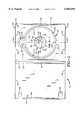
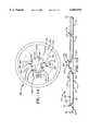
- FIG. 1is a top plan view of a storage container for an item of recorded media depicted in an open position
- FIG. 2is an enlarged top plan view of the hub encircled by the line labeled FIG. 2 in FIG. 1;
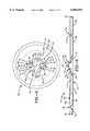
- FIG. 3is an enlarged sectional view taken along line 3--3 of FIG. 1;
- FIG. 4is an enlarged side view of the hub taken along line 4--4 of FIG. 1;
- FIG. 5is a fragmentary sectional view of the storage container with an item of recorded media disposed above the hub prior to engaging the hub, the hub being in a resting position;
- FIG. 6is a view similar to FIG. 5 with the item of recorded media initially engaging the hub;
- FIG. 7is a view similar to FIG. 5 depicting the item of recorded media fully engaging the hub while it is being installed on the hub;
- FIG. 8is a view similar to FIG. 5 with the item of recorded media in the storage position on the hub;
- FIG. 9is a view similar to FIG. 5 depicting the item of recorded media being removed from the hub;
- FIG. 10is a view similar to FIG. 5 depicting the item of recorded media having been fully removed from the hub;
- FIG. 11is a view similar to FIG. 2 showing an enlarged top plan view of a first alternative embodiment of the hub of the present invention
- FIG. 12is a view similar to FIG. 11 showing a second alternative embodiment of the hub of the present invention.
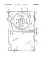
- FIG. 13is a top plan view of a storage container for an item of recorded media depicted an open position having a third alternative embodiment of the hub of the present invention
- FIG. 14is an enlarged top plan view of the third alternative embodiment of the hub that is encircled by the line labeled FIG. 14 in FIG. 13;
- FIG. 15is a sectional view taken along line 15--15 of FIG. 13;
- FIG. 16is a fragmentary sectional view of the storage container with an item of recorded media disposed on the hub in the storage position;
- FIG. 17is a view similar to FIG. 16 depicting the item of recorded media being removed from the hub;
- FIG. 18is a view similar to FIG. 16 depicting the item of recorded media being released from the hub;
- FIG. 19is a view similar to FIG. 16 depicting the item of recorded media fully removed from the hub.
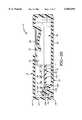
- FIG. 20is a sectional view taken through two different parts of the storage container of the present invention when the storage container is closed showing the relationship between the item of recorded media, the rib projecting from the back wall, and the literature held by the storage container.
- Storage container 10includes a base, indicated generally by the numeral 12, that is hingedly attached to a lid 14.
- the hinged connection between base 12 and lid 14is formed by a back wall 16 and a pair of continuous living hinges 18.
- a rib 19projects outwardly from back wall 16 and is substantially perpendicular to back wall 16.
- Rib 19is configured to extend over the item of recorded media to help retain the item when storage container 10 is closed.
- Base 12includes a sidewall 20 that extends about three sides of base 12 attached to living hinge 18.
- Sidewall 20includes a plurality of reinforcing ribs 22.
- Lid 14may also have a sidewall 24 that extends about the three sides of lid 14 not connected to living hinge 18. Sidewall 24 may have latches that keep container 10 closed. Lid 14 may also include a pair of clips 26 that may be used to hold printed material 27 (see FIG. 20) that describes the material on the item of recorded media stored in storage container 10. Printed material 27 is carried by clips 26 and rib 19 as shown in FIG. 20. Storage container 10 may be fabricated from any of a wide variety of materials but it is preferred that it be fabricated from a plastic strong enough to resist breaking when dropped during a drop test.
- storage container 10includes a hub 30 that is configured and adapted to selectively receive an item of recorded media 32 in a secure manner while allowing item 32 to rotate freely on hub 30 within storage container 10.
- Hub 30also allows item 32 to be quickly and easily removed from hub 30 while not creating excessive bending stresses in item 32.
- Storage container 10also includes an outer wall 34 that is spaced from hub 30 but fully surrounds hub 30.
- Outer wall 34is configured and adapted to prevent a user from improperly removing item 32 of recorded media from storage container 10.
- Outer wall 34also cooperates with hub 30 to prevent item 32 from experiencing excessive bending stresses when item 32 is placed into storage container 10.
- Outer wall 34further cooperates with hub 30 to allow item 32 to freely rotate while in the stored position while experiencing minimal friction.
- Outer wall 34also functions to allow item 32 to be easily removed from storage container 10.
- Outer wall 34further protects item 32.
- Item of recorded media 32is in the form of a disc in the preferred embodiment of the present invention.
- Item 32may be a typical compact disc or DVD which each have an outer diameter defined by the substantially circular outer edge or wall 36 of item 32.
- Item 32also includes an upper surface 38 and a lower surface 40 that are both substantially planar. The distance between upper surface 38 and lower surface 40 of item 32 defines the thickness of item 32.
- Item 32further includes an inner wall 42 that is substantially circular and defines an inner hole 44 that has a hole diameter.
- the machine-readable information stored on item of recorded media 32extends from a location adjacent to but spaced from outer edge 36 of item 32 across a middle area 45 to an area adjacent to but spaced from inner wall 42 of item 32 (see FIG. 5). The information is typically spaced farther from inner wall 42 than outer edge 36 such that an inner area 46 surrounding inner wall 42 does not contain machine-readable information whereby that area may be used to hold item of recorded media 32 while it is being played in an appropriate machine.
- Base 12 of storage container 10includes a bottom wall 50 that is substantially planar and includes an upper surface 52.
- Hub 30extends up from bottom wall 50.
- Hub 30includes a first support platform 54 that is carried above bottom wall 50 of base 12 by an annular spacing wall 56.
- annular spacing wall 56is sloped between first support platform 54 and bottom wall 50.
- annular spacing wall 56may be perpendicular to both bottom wall 50 and first support platform 54.
- annular spacing wall 56may not be continuous about the entire periphery of first support platform 54.
- first support platform 54is spaced above upper surface 52 of bottom wall 50 so as to provide a space or gap under lower surface 40 of item 32 when item 32 is in the stored position in storage container 10 as depicted in FIG. 8. This gap prevents item 32 from experiencing any friction in the area of item 32 that is disposed above upper surface 52 when item 32 is in the storage position.
- Annular spacing wall 56is also configured to place item 32 at a level with respect to bottom wall 50 such that a user can fit at least a portion of a finger or thumb below lower surface 40 of item 32 and upper surface 52 of bottom wall 50 to remove item 32 from storage container 10.
- Annular spacing wall 56further provides strength to base 12 by providing a protuberance in the middle portion of base 12 that adds rigidity to storage container 10.
- First support platform 54is substantially circular and provides a lower support to item 32 when item 32 is in the storage position as depicted in FIG. 8.
- a plurality of bumps 60extend upward from upper surface 58 of first support platform 54 to provide essentially frictionless support to item 32.
- three bumps 60are disposed equally about first support platform 54 such that their support is evenly distributed to item 32.
- Other numbers of bumps 60may be used in other embodiments of the present invention.
- Each bump 60is preferably rounded such that minimal contact between bumps 60 and item 32 is provided. The minimal contact creates essentially no friction between bumps 60 and item 32 when item 32 is in the storage position. The reduced friction is important because item 32 is permitted to freely rotate on hub 30 while in the storage position.
- bumps 60may be formed in other shapes that perform the same functions as rounded bumps 60. Bumps 60 are disposed sufficiently inwardly on first support platform 54 so as not to contact the areas of recorded information on item of recorded media 32.
- Hub 30further includes a substantially stable, nonmovable body 62 that extends up from first support platform 54 and a pair of resilient arms 64 that are each cantilevered from first support platform 54.
- Body 62includes a sidewall 66 that is substantially annular about its circumference with the exception of being broken by a pair of inset curves 68 that define areas that are configured to at least partially receive resilient arms 64 as shown in FIG. 2.
- Body 62further includes an upper wall 70 that vaults sidewall 66.
- body 62is adapted and configured to prevent the user from manipulating or damaging resilient arms 64 when the user pushes down on hub 30. Such protection is accomplished by configuring body 62 to be substantially taller than each resilient arm 64. As such, upper wall 70 of body 62 is disposed at a height that is larger than the tallest height of each resilient arm 64. The relative heights may be seen in FIG. 5. In the embodiment of the invention depicted in the drawings, each arm 64 is short enough to flex inward and fit under upper wall 70 of body 62. This characteristic prevents a user's finger or thumb from contacting resilient arms 64 when the user presses the center of body 62 with the finger or thumb.
- Hub 30 of storage container 10functions by preventing any action from occurring when the center (upper wall 70 of body 62) of hub 30 is pushed on by the user. Such force is transmitted from upper wall 70 through sidewall 66 to first support platform 54 into annular spacing wall 56 to bottom wall 50 of base 12. The force applied by a user is thus not transmitted into resilient arms 64 causing them to release item 32.
- Each resilient arm 64is separated from body 62 by a slot 72 that extends from first support platform 54 up next to sidewall 66, adjacent upper wall 70, back down next to sidewall 66, and then out into first support platform 54.
- slots 72do not extend radially from body 62.
- the portion of each slot 72 that is formed in first support platform 54forms an angle with a reference line that passes through a diameter of body 62. The configuration of slots 72 thus allows each resilient arm 64 to be easily deflected by reducing the amount of material supporting each arm 64.
- Each resilient arm 64includes a pair of substantially horizontal support beams 74 that extend between slot 72 and an opening 76 that is formed in first support platform 54 adjacent each resilient arm 64.
- the sizing and configuration of opening 76 and slot 72causes each horizontal support beam 74 to be thin such that resilient arm 64 may be easily deflected inward toward the center of hub 30 upon application of a small force.
- Such easy deflectionis important when an item of recorded media such as a DVD is stored in storage container 10 because it is desirable to minimize the bending forces experienced by the recorded media when it is inserted into and removed from storage container 10.
- Each horizontal support beam 74is tapered such that it's thin end connects with a vertical leg 78 of resilient arms 64.
- the thin ends of each support beam 74function as bending structural members that allow vertical leg 78 to flex inwardly easily.
- the thicker end of horizontal support beam 74merges with first support platform 54 and provides the cantilevered support for each resilient arm 64.
- vertical leg 78 of resilient arm 64extends up from the inner end of horizontal support beam 74 to a location that is below the upper surface of sidewall 66 of body 62.
- An upper arm wall 80extends radially inward from the upper end of vertical leg 78 such that slot 72 has a relatively constant dimension throughout its length.
- upper arm wall 80has a curved inner surface that is complementary to inset curves 68 of body 66.
- Upper arm wall 80is also disposed below upper wall 70 of body 62. As discussed above, this configuration prevents the user from readily contacting upper arm wall 80 of resilient arm 64 when the user exerts force on body 62.
- each vertical leg 78form a diameter, indicated by the dimension line labeled with the numeral 82, that is larger than the outer diameter of sidewalls 66 that is indicated by the dimension line labeled with the numeral 84.
- Each diameter 82 and 84is, however, smaller than the hole diameter of item 32 such that inner wall 42 of item 32 may not contact both sides of sidewall 66 or both vertical legs 78 when item 32 is in the storage position.
- the configurationensures that inner wall 42 will only contact one vertical leg 78 at a time.
- These dimensionsallow item 32 to freely rotate on hub 30 when item 32 is securely retained on hub 30 by body 62 and resilient arms 64.
- the larger diameter 82 of vertical legs 78ensures that item 32 will initially contact arms 64 when removed from container 10 instead of contacting fixed body 62.
- detents 86 and 87project from vertical legs 78 of resilient arms 64.
- Detents 86 and 87are configured to cooperate to have a diameter, indicated by the dimension line labeled by the numeral 88 in FIG. 8, that is larger than the hole diameter of item 32.
- Each detent 86 and 87is disposed above item 32 when item 32 is in the storage position. Detents 86 and 87 thus cooperate to retain item 32 on hub 30 when item 32 is in the storage position as depicted in FIG. 8.
- Detents 86 and 87are shaped differently as may be seen in FIG. 5. Each detent 86 and 87 includes an upper taper 90 that is sized and configured to engage the lower edge of inner wall 42 of item 32 when item 32 is placed over hub 30 as shown in FIG. 6. Upper taper 90 thus extends down from the top surface of upper arm wall 80. Detents 86 and 87 are otherwise differently configured so as to function to hold item 32 in storage container 10 and to allow item 32 to be removed from storage container 10 without experiencing damaging bending forces.
- detents 87is a locking detent that is designed to hold item 32 in its storage position and to not interfere with the removal of item 32 from hub 30.
- Locking detent 87is disposed on the arm 64 that is opposite the finger access hole 96 (discussed in more detail below) that is disposed in outer wall 34.
- Locking detent 87includes a substantially vertical outer face 91 and an undercut wall 92 that is substantially parallel to upper surface 58 of first support platform 54.
- undercut wall 92need not be horizontal and may form a smooth curve between the bottom of outer face 91 and the top of vertical leg 78. Undercut wall may also be angled with respect to horizontal.
- Undercut wall 92are sized and configured to be disposed above a portion of item 32 when item 32 is in the storage position. Undercut wall 92 provides a strong retaining force to item 32 due to its angle with respect to item 32 when an outside force results in item 32 be forced up away from first support platform 54. Such forces occur when storage container 10 is turned upside down or when storage container 10 is dropped during a drop test or by accident.
- Unlocking detent 86is a dual-tapered detent that has a lower taper 93. Lower taper 93 may connect directly to upper taper 90 or may be connected by a smooth curve 94 as depicted in the drawings. Unlocking detent 86 is configured to allow item 32 to contact lower taper 93 and force unlocking detent 86 and its resilient arm 64 inwardly when item 32 is being removed from container 10 by a user.
- lower taper 93provides a retaining force to item 32 because it is disposed above item 32
- lower taper 32is angled more steeply with respect to item 32 than undercut wall 92 is angled with respect to item 32 such that item 32 may slide over lower taper 93 more easily than undercut wall 92.
- storage container 10includes outer wall 34 in addition to hub 30.
- outer wall 34only allows the user to access item of recorded media 32 in a single, predetermined location that is specifically designed to transfer force from item 32 to resilient arms 64.
- Outer wall 34thus ensures that the user of storage container 10 will remove item of recorded media 32 in the proper manner whereby any harmful bending stresses in item of recorded media 32 are minimized.
- Outer wall 34achieves this limitation by blocking access to item of recorded media 32 by the user about all of the perimeter of item of recorded media 32 but for a single finger access hole 96.
- finger access hole 96has a lower surface 98 that is disposed below upper surface 52 of bottom wall 50.
- the location of lower surface 98provides extra room for the user to grasp item 32 when item 32 is in the storage position depicted in FIG. 8.
- the sidewall 100 of finger access hole 96is dished so as to provide a smooth transition and entrance for the finger or thumb of the user.
- Finger access hole 96is aligned with resilient arms 64 such that a reference line 101 that bisects each resilient arm 64 also bisects finger access hole 96. This arrangement causes the user to exert force on item 32 in a direction that causes the force to be directly transferred to resilient arms 64 such that at least one arm 64 will immediately deflect and start to release item 32.
- the thinness of support beams 74also assists in the immediate reaction in arms 64.
- the provision of only a single finger access hole 96also forces the user to properly remove item 30 from container 10.
- Some prior art storage containersallow the user to grasp the disc on either side of a hub thus squeezing and bending the disc.
- the provision of a pair of finger access holesalso allows the user to choose which side of the disc to initially pick up. The present invention eliminates such choice by only providing the single finger access hole 96.
- outer wall 34extends entirely about the outer periphery of item 32 to prevent the user from grasping outer edge 36 of item 32 when item 32 is in the storage position.
- outer wall 34includes a blocking wall 102 that extends upwardly from bottom wall 50 of storage container 10.
- Blocking wall 102is substantially perpendicular to bottom wall 50 and extends to a height that is above upper surface 38 of item 32 when item 32 is in the storage position.
- Blocking wall 102has an inner surface 104 that has an inner diameter that is greater than the outer diameter of item 32 such that item 32 does not contact any portion of blocking wall 102 when item 32 is in the storage position.
- Such a configurationalso provides no friction between blocking wall 102 and item 32 when item 32 is free to rotate on hub 30. Blocking wall 102 further protects outer wall 36 of item 32.
- Outer wall 34further includes a second support platform 106 that extends entirely about outer wall 34 except for the area where finger access hole 96 interrupts outer wall 34.
- Second support platform 106has an upper surface 108 that is at substantially the same height and substantially planar with upper surface 58 of first support platform 54.
- Outer wall 34further includes a plurality of bumps 110 that project upwardly from second support platform 106.
- Each bump 110is substantially similar to bumps 60 disposed on first support platform 54 such that bumps 110 and bumps 60 are substantially at the same height.
- Bumps 110are also preferably rounded to provide minimal friction between item 32 and bumps 110. In the preferred embodiment of the present invention, three bumps 110 are equally dispersed about outer wall 34. Bumps 110 are oppositely disposed with respect to bumps 60. Bumps 110 and 60 thus cooperate to support item of recorded media 32 in a substantially frictionless manner such that item 32 may rotate freely on hub 30 while in the storage position. A different number of bumps may be used in other embodiments of the present invention.
- FIGS. 5-10The operation of storage container 10 is depicted in FIGS. 5-10.
- item of recorded media 32is completely removed from storage container 10.
- Item of recorded media 32is placed on storage container 10 by first positioning item of recorded media 32 above hub 30 such that inner hole 44 of item 32 is substantially aligned with body 62 and resilient arms 64.
- the userthen places item 32 into contact with detents 86 and 87 on resilient arms 64. This position is depicted in FIG. 6.
- the userapplies substantially even force as indicated by the arrows labeled with numeral 112.
- Force 112is transmitted by item 32 to detents 86 and 87 and particularly upper taper 90 of detents 86 and 87.
- the force on upper tapers 90causes each resilient arm 64 to flex inwardly as depicted in FIG. 7.
- each resilient armis indicated by the arrow labeled with the numeral 114.
- the usermaintains force 112 until item 32 gently snaps over detents 86 and 87 to the storage position as depicted in FIG. 8.
- the force that is required to deflect each arm 64 inwardlyis small and not large enough to cause damage to a recorded media. Arms 64 deflect inwardly easily due to the dimensions of support beams 74.
- resilient arms 64flex back outwardly to their resting position. As described above, the outer surface of each resilient arm 64 does not contact inner wall 42 of item 32 in tandem. In this position, item 32 is supported from below by bumps 60 and 110 while being supported from above by lower taper 93 and undercut wall 92. Undercut wall 92 and lower taper 93 are sized to be large enough to prevent item 32 from falling off hub 30 during the industry drop test that is performed on storage container 10.
- Item 32does not contact any portion of blocking wall 102. Item 32 is thus free to rotate and is only loosely held by storage container 10. Item 32 thus is free from damaging bending stresses that can harm item 32 when it is stored for an extended period of time in a storage container. The supporting forces provided by bumps 60 and 110 prevent item 32 from experiencing damaging bending stresses if the user applies additional downward force on item once it is in the storage position. Item 32 is thus supported at its inner portion and at its outer portion when it is in the storage position. Furthermore, if the user attempts to push the center of hub 30 to release item 32 from its storage position, upper wall 70 of body 62 remains stable and prevents the user from accidentally manipulating or damaging resilient arms 64.
- storage container 10When item 32 is in the storage position on hub 30, storage container 10 may be closed by bending lid 14 over base 12 at hinges 18 to move back wall 16 in an orientation where it is substantially perpendicular to lid 14 in base 12. In this position, rib 19 is substantially parallel to lid 14 in base 12 and extends over at least a portion of item 32 as depicted in FIG. 20. Rib 19 thus helps retain item 32 in its storage position. It has been found that rib 19 is especially useful when storage container 10 is dropped and experiences an impact force that can jar item 32 from hub 30.
- Item of recorded media 32is removed from storage container 10 by the user when the user places a finger or a thumb in finger access hole 96 and contacts the edge of item 32 that is disposed in finger access hole 96.
- the contact between the user's finger or thumb and outer edge 36 of item 32forces item 32 away from finger access hole 96 such that inner wall 42 is forced against the radial outer surface of leg 78 that is adjacent finger access hole 96.
- inner wall 42is pushed away from leg 78 of resilient arm 64 that is opposite finger access hole 96 thus moving item 32 as far out as possible from under undercut wall 92.
- the location of the single finger access hole 96causes inner wall 42 of item 30 to be forced back into unlocking detent 86 and moved substantially free of locking detent 87 when the user inserts a finger or thumb into finger access hole 96. If the user could grasp both sides of item 30, inner wall 42 would likely be lifted upwardly into both detents 86 and 87 simultaneously preventing item 32 from being easily removed from container 10.
- a first alternative embodiment of the hub for storage container 10is depicted in FIG. 11 and is indicated by the numeral 200.
- Hub 200includes substantially the same elements as hub 30 described above except that resilient arms 64 are disposed 90 degrees from each other instead of 180 degrees from each other.
- a second alternative embodiment of the hub for storage container 10is depicted in FIG. 12 and is indicated by the numeral 250.
- Hub 250includes a third arm 64 with arms 64 equally dispersed about body 62.
- Each hub 200 and 250functions to retain item 32 in storage container 10 in substantially the same manner as described above in respect to hub 30.
- FIGS. 13-19A third alternative embodiment of the hub for storage container 10 of the present invention is depicted in FIGS. 13-19 and is indicated by the numeral 300.
- Hub 300is formed in base 12 and has substantially the same relation to base 12, lid 14, back wall 16, and outer wall 34 as hub 30 described above. In view of the similarities, only the specific structure of hub 300 will now be described with it being understood that the structure of outer wall 34, base 12, lid 14, and back wall 16 are substantially as described above.
- Base 12 of storage container 10contains bottom wall 50 that is substantially planar and includes upper surface 52 as described above.
- Hub 300extends up from bottom wall 50.
- Hub 300includes a first support platform 354 that is carried above bottom wall 50 of base 12 by an annular spacing wall 356.
- Annular spacing wall 356may be sloped between first support platform 354 and bottom wall 50.
- the upper surface 358 of first support platform 354is spaced above upper surface 52 of bottom wall 50 so as to provide a gap under lower surface 40 of item 32 when item 32 is in the storage position in storage container 10 as depicted in FIG. 16. This gap prevents item 32 from experiencing any friction in the area of item 32 that is disposed above upper surface 52 when item 32 is in the storage position.
- Annular spacing wall 356is also configured to place item 32 at a level with respect to bottom wall 50 such that a user can fit at least a portion of a finger or thumb below lower surface 40 of item 32 and upper surface 52 of bottom wall 50 to remove item 32 from storage container 10. Annular spacing wall 356 further provides strength to base 12 by providing a protuberance in the middle portion of base 12 that adds rigidity to storage container 10.
- First support platform 354is substantially circular and provides a lower support to item 32 when item 32 is in the storage position as depicted in FIG. 16.
- a plurality of bumps 360extend up from upper surface 358 of first support platform 354 to provide essentially frictionless support to item 32.
- three bumps 360are disposed equally about first support platform 354 such that their support is evenly distributed to item 32.
- Other numbers of bumps 360may be used in other embodiments of the present invention.
- Each bump 360is preferably rounded to provide minimal contact between bumps 360 and item 32. The minimal contact creates essentially no friction between bumps 360 and item 32 when item 32 is in the storage position. The reduced friction is important because item 32 is permitted to freely rotate on hub 300 while in the storage position.
- bumps 360may be formed in other shapes that perform the same functions as rounded bumps 360. Bumps 360 are disposed sufficiently inward on first support platform 354 so as not to contact the areas of recorded information on item 32.
- Hub 300further includes a first resilient arm 362 and a second resilient arm 364 that are each cantilevered from first support platform 354.
- First resilient arm 362includes a side wall 366 that is substantially annular about its circumference with the exception of being broken by an inset curve 368 that defines an area that at least partially receives resilient arm 364 as shown in FIG. 14.
- Arm 362further includes an upper wall 370 that vaults side wall 366.
- first resilient arm 362is adapted and configured to allow the user to depress arm 362 when the user pushes down on top wall 370.
- Such actionallows the user to easily remove item 32 of recorded media from hub 300 with essentially no contact occurring between item 32 and hub 300 that could cause a damaging bending stress from occurring in item 32.
- upper wall 370 of arm 362is disposed at a height that is taller than the tallest position of resilient arm 364. The relative heights may be seen in FIG. 16.
- Each arm 362 and 364is cantilevered from first support platform 354 by a substantially horizontal support beam 374 that is defined by a slot 372 that extends around side wall 366 and extends outwardly into first support platform 354.
- slot 372extends farther into platform 354 when defining horizontal support beam 74 that supports first resilient arm 362 than it does when defining beam 74 that supports second resilient arm 364.
- FIG. 14shows that slot 372 extends through about a quarter to half of the width of support platform 354 when defining beam 74 that supports arm 364.
- Slot 372extends over half of the width of support platform 354 when defining beam 74 that supports arm 362. This configuration allows first resilient arm 362 to be more flexible than second resilient arm 364 and allows arm 362 to be depressed as depicted in FIGS. 17 and 18.
- each resilient arm 362 and 364includes a vertical leg 378 that extends up from the inner ends of horizontal support beams 374.
- the upper end of vertical leg 378 of resilient arm 362connects with top wall 370.
- the upper end of vertical leg 378 of resilient arm 364connects with an upper arm wall 380 that extends radially inward toward inset curve 368.
- Upper arm wall 380has a curved inner surface that is complimentary to inset curve 368.
- Upper arm wall 380is also disposed below top wall 370 of arm 362. This configuration allows the user of storage container 10 having hub 300 to easily contact top surface 370 and depress resilient arm 362.
- each vertical leg 378form a distance, indicated by the dimension line labeled with the numeral 382, that is larger than the outer diameter of side wall 366 that is indicated by the dimension line labeled 384.
- Each distance 382 and 384is, however, smaller than the hole diameter of item 32 such that inner wall 42 of item 32 is not permitted to contact both sides of side wall 366 or both vertical legs when item 32 is in the storage position.
- the configurationensures that inner wall 42 will only contact one surface at a time.
- detents 386 and 387project from vertical legs 378 of resilient arms 362 and 364.
- Detents 386 and 387are configured to cooperate to have a diameter, indicated by the dimension line labeled by the numeral 388 in FIG. 16, that is larger than the hole diameter of item 32.
- Each detent 386 and 387is disposed above item 32 when item 32 is in the storage position. Detents 386 and 387 thus cooperate to retain item 32 on hub 300 when item 32 is in the storage position as depicted in FIG. 16.
- Detents 386 and 387may be shaped differently as described above with respect to hub 30 and detents 86 and 87. However, in hub 300, detents 386 and 387 may be substantially the same shape as depicted in FIGS. 16-19. Each detent 386 and 387 is a dual-taped detent having an upper taper 390 and a lower taper 393. Lower taper 393 connects directly with upper taper 390 in a smooth curve as depicted in the drawings.
- storage container 10includes outer wall 34 in addition to hub 300.
- outer wall 34only allows the user to access item of recorded media 32 in a single, predetermined location that is specifically designed to force the user of storage container 10 to remove item 32 in the proper manner thereby minimizing any harmful bending stresses in item 32 during the removal procedure.
- Outer wall 34creates this limitation by blocking access to item 32 by the user about all of the perimeter of item 32 but for a single finger access hole 96. The structure of finger access hole 96 and outer wall 34 are described above.
- FIGS. 16-19The operation of storage container 10 and hub 300 is depicted in FIGS. 16-19.
- Item 32 of recorded mediais placed on hub 300 in substantially the same manner as described above with respect to hub 30 and as depicted in FIGS. 5-7. Once item 32 has been forced over detents 386 and 387, it rests in the storage position depicted in FIG. 16. The steps of removing item 32 from hub 300 are depicted in FIGS. 16-19.
- Item of recorded media 32may be removed from hub 300 and storage container 10 by the user in two different ways. First, item 32 may be removed as described above with respect to hub 30 by simply placing a finger or thumb in finger access hole 96 and lifting the edge of item 32 away from storage container 10.
- the other way of removing item 32allows item 32 to be removed from hub 300 with essentially no contact between item 32 and hub 300.
- the userfirst depresses resilient arm 362 by depressing top wall 370 as indicated by the arrow labeled by numeral 400.
- the act of depressing resilient arm 362causes detent 386 to move radially inward allowing the user to lift the edge of item 32 as indicated by the arrow labeled with numeral 402.
- the usermay lift item 32 over detent 386 with essentially no contact, if any, when resilient arm 362 is in the depressed position depicted in FIGS. 17-18.
- the improved storage container for recorded mediais simplified, provides an effective, safe, inexpensive, and efficient device which achieves all the enumerated objectives, provides for eliminating difficulties encountered with prior devices, and solves problems and obtains new results in the art.
Landscapes
- Packaging For Recording Disks (AREA)
Abstract
Description
Claims (28)
Priority Applications (7)
| Application Number | Priority Date | Filing Date | Title |
|---|---|---|---|
| US09/245,944US6065594A (en) | 1998-04-01 | 1999-02-05 | Storage container for recorded media |
| PCT/US1999/030225WO2000046127A1 (en) | 1999-02-05 | 1999-12-17 | Storage container for recorded media |
| DE69933584TDE69933584T2 (en) | 1999-02-05 | 1999-12-17 | MEMORY DEVICE FOR RECORDING CARRIER |
| EP99967419AEP1156972B1 (en) | 1999-02-05 | 1999-12-17 | Storage container for recorded media |
| AU23700/00AAU2370000A (en) | 1999-02-05 | 1999-12-17 | Storage container for recorded media |
| US09/544,647US6354435B1 (en) | 1998-04-01 | 2000-04-05 | Storage container for recorded media |
| US10/095,671US6789667B2 (en) | 1998-04-01 | 2002-03-11 | Storage container for recorded media |
Applications Claiming Priority (3)
| Application Number | Priority Date | Filing Date | Title |
|---|---|---|---|
| US8036398P | 1998-04-01 | 1998-04-01 | |
| US09/108,635US5996788A (en) | 1998-04-01 | 1998-07-01 | Storage container for recorded media |
| US09/245,944US6065594A (en) | 1998-04-01 | 1999-02-05 | Storage container for recorded media |
Related Parent Applications (1)
| Application Number | Title | Priority Date | Filing Date |
|---|---|---|---|
| US09/108,635Continuation-In-PartUS5996788A (en) | 1998-04-01 | 1998-07-01 | Storage container for recorded media |
Related Child Applications (3)
| Application Number | Title | Priority Date | Filing Date |
|---|---|---|---|
| US29/101,486Continuation-In-PartUSD439435S1 (en) | 1998-07-01 | 1999-03-05 | Hub for holding recorded media |
| US29/101,485Continuation-In-PartUSD430424S (en) | 1999-03-05 | 1999-03-05 | Tray for holding recorded media |
| US09/544,647Continuation-In-PartUS6354435B1 (en) | 1998-04-01 | 2000-04-05 | Storage container for recorded media |
Publications (1)
| Publication Number | Publication Date |
|---|---|
| US6065594Atrue US6065594A (en) | 2000-05-23 |
Family
ID=22928735
Family Applications (1)
| Application Number | Title | Priority Date | Filing Date |
|---|---|---|---|
| US09/245,944Expired - Fee RelatedUS6065594A (en) | 1998-04-01 | 1999-02-05 | Storage container for recorded media |
Country Status (5)
| Country | Link |
|---|---|
| US (1) | US6065594A (en) |
| EP (1) | EP1156972B1 (en) |
| AU (1) | AU2370000A (en) |
| DE (1) | DE69933584T2 (en) |
| WO (1) | WO2000046127A1 (en) |
Cited By (39)
| Publication number | Priority date | Publication date | Assignee | Title |
|---|---|---|---|---|
| USD437505S1 (en) | 1999-06-24 | 2001-02-13 | Dubois Limited | Portion of a disk holder |
| US6227362B1 (en)* | 2000-02-02 | 2001-05-08 | Forward Electronics Manufacturing Company Limited | Audio-visual box |
| US6237763B1 (en)* | 2000-05-11 | 2001-05-29 | Kwok Din Lau | Disk protection enclosure |
| US6298986B1 (en)* | 2000-06-19 | 2001-10-09 | Kun-Fa Chang | Compact disk receiving device |
| US6354435B1 (en)* | 1998-04-01 | 2002-03-12 | Nexpak Corporation | Storage container for recorded media |
| US6364108B1 (en)* | 2000-06-19 | 2002-04-02 | Cmc Magnetics Corporation | Box for packaging or storing DVDs CDs and/or VCDs |
| US6412631B2 (en)* | 1998-04-01 | 2002-07-02 | Nexpak Corporation | Storage container for recorded media |
| US6415918B1 (en)* | 1999-02-24 | 2002-07-09 | Concord Continental Ltd. | Optical disc holder |
| WO2002066342A1 (en)* | 2001-02-20 | 2002-08-29 | Nexpak Corporation | Storage container for recorded media |
| US6464073B1 (en)* | 2000-11-13 | 2002-10-15 | Triple Keen Industrial Ltd. | Compact disc holder |
| USD464974S1 (en) | 2000-08-03 | 2002-10-29 | Alan L. Abeyta | Compact disc securing device |
| USD466718S1 (en) | 2000-08-03 | 2002-12-10 | Edward L. Abeyta, Jr. | Compact disc securing device |
| EP1160792A3 (en)* | 2000-05-30 | 2003-01-08 | Victor Company Of Japan, Limited | Container for disk |
| US6561347B1 (en) | 1999-11-02 | 2003-05-13 | Autronic Plastics, Inc. | Case and lock with improved disc protection |
| US20030150755A1 (en)* | 2002-02-11 | 2003-08-14 | Chen Kun Chang | Compact disk case |
| US6648135B2 (en)* | 2000-07-05 | 2003-11-18 | Wing Shing Optical Disc Co., Ltd. | Disk storage holder |
| US6729469B1 (en)* | 2002-10-28 | 2004-05-04 | Technicolor Videocassette, Inc. | Storage holder for a compact disc |
| US20050077196A1 (en)* | 2003-10-10 | 2005-04-14 | Enxnet, Inc. | Optical disk storage case |
| US20050167302A1 (en)* | 2003-09-08 | 2005-08-04 | Jan Bjerregaard | Metal packaging |
| USD508813S1 (en) | 2002-05-31 | 2005-08-30 | Nexpak Corporation | Low profile disc storage container |
| US6951278B2 (en) | 2000-10-05 | 2005-10-04 | Nexpak Corporation | Disc holding apparatus |
| US7028835B1 (en) | 2002-11-07 | 2006-04-18 | Rock-Tenn Shared Services, Llc | Disk packaging |
| US7140489B2 (en) | 2003-03-26 | 2006-11-28 | Autronic Plastics, Inc. | Denial system for securing an asset within a container and methods of use |
| USD543067S1 (en)* | 2004-01-13 | 2007-05-22 | Tat Tsuen Industrial Ltd. | DVD holder |
| USD543068S1 (en)* | 2004-01-13 | 2007-05-22 | Tat Tsuen Industrial Ltd. | DVD holder |
| USD544743S1 (en) | 2005-09-26 | 2007-06-19 | Autronic Plastics, Inc. | Media storage case |
| USD545107S1 (en)* | 2003-08-27 | 2007-06-26 | Tenma Corporation | Recording medium container |
| US7257971B2 (en) | 2000-07-31 | 2007-08-21 | Autronics Plastics Inc. | Case with internal lock |
| USD558191S1 (en) | 2004-06-09 | 2007-12-25 | Enxnet, Inc. | Antenna for a storage disc |
| USD557928S1 (en) | 2006-05-26 | 2007-12-25 | Finest Products Limited | Hub |
| US20080006546A1 (en)* | 2006-07-10 | 2008-01-10 | Finest Products Limited | Disk Protective Enclosure |
| US20080041742A1 (en)* | 2006-08-18 | 2008-02-21 | Finest Products Limited | Security Disk Protective Enclosure |
| US20080041743A1 (en)* | 2006-08-18 | 2008-02-21 | Finest Products Limited | Disk Protective Enclosure |
| US20080190793A1 (en)* | 2007-02-14 | 2008-08-14 | Pozzoli S.P.A | Container for a disc and the like, with means for disengageable retention of the disc |
| USD580190S1 (en)* | 2002-02-20 | 2008-11-11 | Nexpak Corporation | Media storage container |
| USD605887S1 (en) | 2009-04-30 | 2009-12-15 | Finest Products Limited | DVD case |
| USD615796S1 (en) | 2009-04-30 | 2010-05-18 | Finest Products Limited | DVD case |
| US8054194B2 (en) | 2003-02-10 | 2011-11-08 | Autronic Plastics, Inc. | System and method for verifying a security status of a lockable container |
| US9305598B2 (en) | 2013-04-08 | 2016-04-05 | Disc Graphics Inc. | Package and container assembly and method of manufacturing same |
Families Citing this family (1)
| Publication number | Priority date | Publication date | Assignee | Title |
|---|---|---|---|---|
| NL1026482C2 (en)* | 2004-06-01 | 2005-12-05 | Fountain Tech Bv | Packaging for information carriers. |
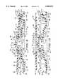
Citations (60)
| Publication number | Priority date | Publication date | Assignee | Title |
|---|---|---|---|---|
| US2600023A (en)* | 1950-12-18 | 1952-06-10 | Frederick H Rice | Record album |
| US3949872A (en)* | 1973-07-19 | 1976-04-13 | Francis Paudras | Individual case for phonograph records |
| US4049120A (en)* | 1976-03-29 | 1977-09-20 | Owens-Illinois, Inc. | Tape reel shipping folder |
| US4120398A (en)* | 1977-09-29 | 1978-10-17 | Mobil Oil Corporation | Packaging support structure |
| US4327831A (en)* | 1979-07-07 | 1982-05-04 | Victor Company Of Japan, Limited | Disk record container |
| US4499994A (en)* | 1983-05-05 | 1985-02-19 | Rentch Bruce W | Phonograph record and album frame |
| US4520470A (en)* | 1982-11-29 | 1985-05-28 | Staar S. A. | Cleaning device for discs |
| US4535888A (en)* | 1983-01-19 | 1985-08-20 | Polygram Gmbh | Storage cassette for two or more disk-shaped high memory density information carriers |
| US4614269A (en)* | 1984-04-27 | 1986-09-30 | Basf Aktiengesellschaft | Packaging container for a tape reel device e.g. a tape cassette |
| US4702369A (en)* | 1986-01-31 | 1987-10-27 | Cinram Ltd./Ltee. | Storage container for records or the like |
| US4709812A (en)* | 1986-07-11 | 1987-12-01 | Agi Incorporated | Compact disc package and a method of making same |
| US4709813A (en)* | 1986-04-10 | 1987-12-01 | Minnesota Mining And Manufacturing Company | Anti-theft device for compact discs |
| US4746013A (en)* | 1986-09-16 | 1988-05-24 | Sony Corporation | Disc cartridge with releasable locking means |
| US4750618A (en)* | 1984-09-24 | 1988-06-14 | Lift Verkaufsgerate-Gesellschaft M.B.H. | Arrangement for securing of recording disk, in particular compact disk plate, against unauthorized taking |
| US4793479A (en)* | 1987-04-02 | 1988-12-27 | Shin-Estu Polymer Co., Ltd. | Holder tray of a compact disc |
| US4805770A (en)* | 1985-01-07 | 1989-02-21 | Polygram International Holding B.V. | Cassette with tray ejection means |
| US4819799A (en)* | 1987-12-18 | 1989-04-11 | Laservideo, Inc. | Optical disc package |
| US4874085A (en)* | 1982-02-16 | 1989-10-17 | Polygram Gmbh | Storage cassette for high storage density, disc-shaped information carriers |
| US4895252A (en)* | 1987-12-18 | 1990-01-23 | Laservideo, Inc. | Optical disc package |
| US4903829A (en)* | 1988-10-07 | 1990-02-27 | Clemens Philip M | Container for compact disc |
| US5101971A (en)* | 1989-08-19 | 1992-04-07 | Philips And Dupont Optical Company | Storage cassette for a disc having a center hole |
| US5168991A (en)* | 1991-10-08 | 1992-12-08 | Himont Incorporated | Compact disc package with moveable carrier |
| US5238107A (en)* | 1992-01-07 | 1993-08-24 | Kownacki Charles D | Disc storage container having a securing means central aperture |
| US5244085A (en)* | 1991-05-23 | 1993-09-14 | Cartonneries De Thulin | Casing for at least one high density data disk |
| US5249677A (en)* | 1992-07-30 | 1993-10-05 | Lim Jin Kyu | Compact disc case |
| US5251750A (en)* | 1992-04-22 | 1993-10-12 | Paul J. Gelardi | Molded CD tray and pop up rosette therefor |
| US5299186A (en)* | 1984-09-29 | 1994-03-29 | Sony Corporation | Disc protecting cover |
| US5310054A (en)* | 1992-04-16 | 1994-05-10 | Sony Corporation | Storage container for disk-shaped object |
| US5322162A (en)* | 1993-06-22 | 1994-06-21 | Outer Circle Products, Ltd. | Compact CD case |
| US5377825A (en)* | 1993-01-04 | 1995-01-03 | Sykes; Philip K. | Compact disc storage case |
| US5400902A (en)* | 1994-01-21 | 1995-03-28 | Kaminski; Andrew | Universal compact disc storage unit |
| US5402882A (en)* | 1993-02-22 | 1995-04-04 | Bandy; Gregory S. | Compact disk holder including disk extractor |
| US5417324A (en)* | 1994-04-08 | 1995-05-23 | Joyce Development Corporation | Clear molded thermoplastic compact disc supporting tray |
| US5450953A (en)* | 1993-04-15 | 1995-09-19 | Reisman; James | Compact disc package with slide tab |
| US5477960A (en)* | 1995-02-09 | 1995-12-26 | Chen; Hsien-Ta | Compact disk case |
| US5494156A (en)* | 1994-07-21 | 1996-02-27 | Optima Precision Inc. | Disc retainer for disc storage device |
| US5515968A (en)* | 1994-06-13 | 1996-05-14 | Taniyama; Yoshihiko | Storage container having an improved hub for gripping an optical disk |
| US5529182A (en)* | 1993-11-12 | 1996-06-25 | Minnesota Mining And Manufacturing Company | Dual disc adapter with downward sloping outside corner wedges |
| US5533612A (en)* | 1993-12-16 | 1996-07-09 | Focke & Co. (Gmbh & Co.) | Hinge-lid pack for cigarettes |
| US5533617A (en)* | 1994-10-31 | 1996-07-09 | Von Flatern; Valerie R. | Paint roller sleeve storage container |
| GB2291640B (en)* | 1994-11-03 | 1996-07-24 | Dubois Plc | Apparatus for holding a compact disk |
| US5558220A (en)* | 1995-06-21 | 1996-09-24 | Owen J. Meegan | Case and tray for holding high density discs |
| US5575388A (en)* | 1996-01-18 | 1996-11-19 | Lakewood Industries, Inc. | Insertable tray for providing a multiple compact disc container |
| US5586651A (en)* | 1994-07-14 | 1996-12-24 | Apparate-Und Werkzeugbau Ag | Disk holder in a CD box |
| US5593030A (en)* | 1995-05-19 | 1997-01-14 | Tell; Richard B. | Compact disc holder |
| US5609249A (en)* | 1995-06-07 | 1997-03-11 | Cheng; Billy | Compact disc holder assembly |
| US5626225A (en)* | 1995-10-23 | 1997-05-06 | Joyce Development Corporation | Multiple compact disc supporting tray |
| US5651458A (en)* | 1996-01-04 | 1997-07-29 | Brosmith; Sean B. | Compact disc storage device |
| US5660274A (en)* | 1996-02-26 | 1997-08-26 | Ponica Industrial Co., Ltd. | Compact disc tray |
| US5682990A (en)* | 1996-11-08 | 1997-11-04 | Schluger; Allen | CD holder for CD jewel box |
| US5682988A (en)* | 1996-03-21 | 1997-11-04 | Salisbury; Philip S. | Disc storage case |
| GB2312665A (en)* | 1996-04-30 | 1997-11-05 | Dubois Plc | Holder for a compact disk |
| US5685425A (en)* | 1995-02-16 | 1997-11-11 | Viva Magnetics Limited | CD box with T-shape clamping elements |
| US5685427A (en)* | 1996-05-03 | 1997-11-11 | Ultrapac, Inc. | Holder for removably supporting a compact disk |
| US5727680A (en)* | 1995-09-11 | 1998-03-17 | Liu; Tak Lun | Impact resistant compact disc tray structure |
| US5775491A (en)* | 1996-05-15 | 1998-07-07 | Atlanta Precision Molding Company | Compact disk tray and cover therefor |
| US5785172A (en)* | 1995-12-28 | 1998-07-28 | Lakewood Industries, Inc. | Double rosette for compact disc container |
| US5799782A (en)* | 1995-04-10 | 1998-09-01 | Gelardi; John A. | Compact disc case |
| US5887713A (en)* | 1995-10-26 | 1999-03-30 | Ultrapac, Inc. | Holder for compact discs |
| US5938020A (en)* | 1997-01-25 | 1999-08-17 | Luckow; Hans-Juergen | CD-cassette with holder |
Family Cites Families (5)
| Publication number | Priority date | Publication date | Assignee | Title |
|---|---|---|---|---|
| DE4332183A1 (en)* | 1993-09-22 | 1995-03-23 | Roland Heckmann | Support part for CDs |
| AUPN239695A0 (en)* | 1995-04-13 | 1995-05-11 | Mcewan, Sturt | Compact disc cassette case |
| US5819928A (en)* | 1996-04-22 | 1998-10-13 | Wynalda Litho, Inc. | Packaging container for recordings and the like |
| US5816394A (en)* | 1997-07-23 | 1998-10-06 | Ivy Hill Corporation | Ecologically acceptable package for a recording medium |
| DE29816281U1 (en)* | 1998-09-10 | 1998-12-17 | topac MultimediaPrint GmbH, 33332 Gütersloh | Packaging for disk-shaped storage medium |
- 1999
- 1999-02-05USUS09/245,944patent/US6065594A/ennot_activeExpired - Fee Related
- 1999-12-17AUAU23700/00Apatent/AU2370000A/ennot_activeAbandoned
- 1999-12-17DEDE69933584Tpatent/DE69933584T2/ennot_activeExpired - Fee Related
- 1999-12-17WOPCT/US1999/030225patent/WO2000046127A1/enactiveIP Right Grant
- 1999-12-17EPEP99967419Apatent/EP1156972B1/ennot_activeExpired - Lifetime
Patent Citations (61)
| Publication number | Priority date | Publication date | Assignee | Title |
|---|---|---|---|---|
| US2600023A (en)* | 1950-12-18 | 1952-06-10 | Frederick H Rice | Record album |
| US3949872A (en)* | 1973-07-19 | 1976-04-13 | Francis Paudras | Individual case for phonograph records |
| US4049120A (en)* | 1976-03-29 | 1977-09-20 | Owens-Illinois, Inc. | Tape reel shipping folder |
| US4120398A (en)* | 1977-09-29 | 1978-10-17 | Mobil Oil Corporation | Packaging support structure |
| US4327831A (en)* | 1979-07-07 | 1982-05-04 | Victor Company Of Japan, Limited | Disk record container |
| US4874085A (en)* | 1982-02-16 | 1989-10-17 | Polygram Gmbh | Storage cassette for high storage density, disc-shaped information carriers |
| US4520470A (en)* | 1982-11-29 | 1985-05-28 | Staar S. A. | Cleaning device for discs |
| US4535888A (en)* | 1983-01-19 | 1985-08-20 | Polygram Gmbh | Storage cassette for two or more disk-shaped high memory density information carriers |
| US4499994A (en)* | 1983-05-05 | 1985-02-19 | Rentch Bruce W | Phonograph record and album frame |
| US4614269A (en)* | 1984-04-27 | 1986-09-30 | Basf Aktiengesellschaft | Packaging container for a tape reel device e.g. a tape cassette |
| US4750618A (en)* | 1984-09-24 | 1988-06-14 | Lift Verkaufsgerate-Gesellschaft M.B.H. | Arrangement for securing of recording disk, in particular compact disk plate, against unauthorized taking |
| US5299186A (en)* | 1984-09-29 | 1994-03-29 | Sony Corporation | Disc protecting cover |
| US4805770A (en)* | 1985-01-07 | 1989-02-21 | Polygram International Holding B.V. | Cassette with tray ejection means |
| US4702369A (en)* | 1986-01-31 | 1987-10-27 | Cinram Ltd./Ltee. | Storage container for records or the like |
| US4709813A (en)* | 1986-04-10 | 1987-12-01 | Minnesota Mining And Manufacturing Company | Anti-theft device for compact discs |
| US4709812A (en)* | 1986-07-11 | 1987-12-01 | Agi Incorporated | Compact disc package and a method of making same |
| US4746013A (en)* | 1986-09-16 | 1988-05-24 | Sony Corporation | Disc cartridge with releasable locking means |
| US4793479A (en)* | 1987-04-02 | 1988-12-27 | Shin-Estu Polymer Co., Ltd. | Holder tray of a compact disc |
| US4895252A (en)* | 1987-12-18 | 1990-01-23 | Laservideo, Inc. | Optical disc package |
| US4819799A (en)* | 1987-12-18 | 1989-04-11 | Laservideo, Inc. | Optical disc package |
| US4903829A (en)* | 1988-10-07 | 1990-02-27 | Clemens Philip M | Container for compact disc |
| US5101971A (en)* | 1989-08-19 | 1992-04-07 | Philips And Dupont Optical Company | Storage cassette for a disc having a center hole |
| US5244085A (en)* | 1991-05-23 | 1993-09-14 | Cartonneries De Thulin | Casing for at least one high density data disk |
| US5168991A (en)* | 1991-10-08 | 1992-12-08 | Himont Incorporated | Compact disc package with moveable carrier |
| US5238107A (en)* | 1992-01-07 | 1993-08-24 | Kownacki Charles D | Disc storage container having a securing means central aperture |
| US5310054A (en)* | 1992-04-16 | 1994-05-10 | Sony Corporation | Storage container for disk-shaped object |
| US5251750A (en)* | 1992-04-22 | 1993-10-12 | Paul J. Gelardi | Molded CD tray and pop up rosette therefor |
| US5249677A (en)* | 1992-07-30 | 1993-10-05 | Lim Jin Kyu | Compact disc case |
| US5377825A (en)* | 1993-01-04 | 1995-01-03 | Sykes; Philip K. | Compact disc storage case |
| US5402882A (en)* | 1993-02-22 | 1995-04-04 | Bandy; Gregory S. | Compact disk holder including disk extractor |
| US5450953A (en)* | 1993-04-15 | 1995-09-19 | Reisman; James | Compact disc package with slide tab |
| US5322162A (en)* | 1993-06-22 | 1994-06-21 | Outer Circle Products, Ltd. | Compact CD case |
| US5529182A (en)* | 1993-11-12 | 1996-06-25 | Minnesota Mining And Manufacturing Company | Dual disc adapter with downward sloping outside corner wedges |
| US5533612A (en)* | 1993-12-16 | 1996-07-09 | Focke & Co. (Gmbh & Co.) | Hinge-lid pack for cigarettes |
| US5400902A (en)* | 1994-01-21 | 1995-03-28 | Kaminski; Andrew | Universal compact disc storage unit |
| US5417324A (en)* | 1994-04-08 | 1995-05-23 | Joyce Development Corporation | Clear molded thermoplastic compact disc supporting tray |
| US5515968A (en)* | 1994-06-13 | 1996-05-14 | Taniyama; Yoshihiko | Storage container having an improved hub for gripping an optical disk |
| US5586651A (en)* | 1994-07-14 | 1996-12-24 | Apparate-Und Werkzeugbau Ag | Disk holder in a CD box |
| US5494156A (en)* | 1994-07-21 | 1996-02-27 | Optima Precision Inc. | Disc retainer for disc storage device |
| US5533617A (en)* | 1994-10-31 | 1996-07-09 | Von Flatern; Valerie R. | Paint roller sleeve storage container |
| GB2291640B (en)* | 1994-11-03 | 1996-07-24 | Dubois Plc | Apparatus for holding a compact disk |
| US5788068A (en)* | 1994-11-03 | 1998-08-04 | Dubois Limited | Apparatus for holding a compact disk |
| US5477960A (en)* | 1995-02-09 | 1995-12-26 | Chen; Hsien-Ta | Compact disk case |
| US5685425A (en)* | 1995-02-16 | 1997-11-11 | Viva Magnetics Limited | CD box with T-shape clamping elements |
| US5799782A (en)* | 1995-04-10 | 1998-09-01 | Gelardi; John A. | Compact disc case |
| US5593030A (en)* | 1995-05-19 | 1997-01-14 | Tell; Richard B. | Compact disc holder |
| US5609249A (en)* | 1995-06-07 | 1997-03-11 | Cheng; Billy | Compact disc holder assembly |
| US5558220A (en)* | 1995-06-21 | 1996-09-24 | Owen J. Meegan | Case and tray for holding high density discs |
| US5727680A (en)* | 1995-09-11 | 1998-03-17 | Liu; Tak Lun | Impact resistant compact disc tray structure |
| US5626225A (en)* | 1995-10-23 | 1997-05-06 | Joyce Development Corporation | Multiple compact disc supporting tray |
| US5887713A (en)* | 1995-10-26 | 1999-03-30 | Ultrapac, Inc. | Holder for compact discs |
| US5785172A (en)* | 1995-12-28 | 1998-07-28 | Lakewood Industries, Inc. | Double rosette for compact disc container |
| US5651458A (en)* | 1996-01-04 | 1997-07-29 | Brosmith; Sean B. | Compact disc storage device |
| US5575388A (en)* | 1996-01-18 | 1996-11-19 | Lakewood Industries, Inc. | Insertable tray for providing a multiple compact disc container |
| US5660274A (en)* | 1996-02-26 | 1997-08-26 | Ponica Industrial Co., Ltd. | Compact disc tray |
| US5682988A (en)* | 1996-03-21 | 1997-11-04 | Salisbury; Philip S. | Disc storage case |
| GB2312665A (en)* | 1996-04-30 | 1997-11-05 | Dubois Plc | Holder for a compact disk |
| US5685427A (en)* | 1996-05-03 | 1997-11-11 | Ultrapac, Inc. | Holder for removably supporting a compact disk |
| US5775491A (en)* | 1996-05-15 | 1998-07-07 | Atlanta Precision Molding Company | Compact disk tray and cover therefor |
| US5682990A (en)* | 1996-11-08 | 1997-11-04 | Schluger; Allen | CD holder for CD jewel box |
| US5938020A (en)* | 1997-01-25 | 1999-08-17 | Luckow; Hans-Juergen | CD-cassette with holder |
Cited By (56)
| Publication number | Priority date | Publication date | Assignee | Title |
|---|---|---|---|---|
| US6354435B1 (en)* | 1998-04-01 | 2002-03-12 | Nexpak Corporation | Storage container for recorded media |
| US6412631B2 (en)* | 1998-04-01 | 2002-07-02 | Nexpak Corporation | Storage container for recorded media |
| US6415918B1 (en)* | 1999-02-24 | 2002-07-09 | Concord Continental Ltd. | Optical disc holder |
| USD437505S1 (en) | 1999-06-24 | 2001-02-13 | Dubois Limited | Portion of a disk holder |
| US20050098453A1 (en)* | 1999-11-02 | 2005-05-12 | Autronic Plastics, Inc. | Case and lock with improved disc protection |
| US6561347B1 (en) | 1999-11-02 | 2003-05-13 | Autronic Plastics, Inc. | Case and lock with improved disc protection |
| US6227362B1 (en)* | 2000-02-02 | 2001-05-08 | Forward Electronics Manufacturing Company Limited | Audio-visual box |
| US6237763B1 (en)* | 2000-05-11 | 2001-05-29 | Kwok Din Lau | Disk protection enclosure |
| EP1160792A3 (en)* | 2000-05-30 | 2003-01-08 | Victor Company Of Japan, Limited | Container for disk |
| US6364108B1 (en)* | 2000-06-19 | 2002-04-02 | Cmc Magnetics Corporation | Box for packaging or storing DVDs CDs and/or VCDs |
| US6298986B1 (en)* | 2000-06-19 | 2001-10-09 | Kun-Fa Chang | Compact disk receiving device |
| US6648135B2 (en)* | 2000-07-05 | 2003-11-18 | Wing Shing Optical Disc Co., Ltd. | Disk storage holder |
| US7257971B2 (en) | 2000-07-31 | 2007-08-21 | Autronics Plastics Inc. | Case with internal lock |
| US7260962B2 (en) | 2000-07-31 | 2007-08-28 | Autronics Plastics Inc. | Case with internal lock |
| USD464974S1 (en) | 2000-08-03 | 2002-10-29 | Alan L. Abeyta | Compact disc securing device |
| USD466718S1 (en) | 2000-08-03 | 2002-12-10 | Edward L. Abeyta, Jr. | Compact disc securing device |
| US6951278B2 (en) | 2000-10-05 | 2005-10-04 | Nexpak Corporation | Disc holding apparatus |
| US6464073B1 (en)* | 2000-11-13 | 2002-10-15 | Triple Keen Industrial Ltd. | Compact disc holder |
| US20050173273A1 (en)* | 2001-02-20 | 2005-08-11 | Marsilio Ronald M. | Storage container for recorded media |
| US6799677B2 (en) | 2001-02-20 | 2004-10-05 | Nexpak Corporation | Storage container for recorded media |
| WO2002066342A1 (en)* | 2001-02-20 | 2002-08-29 | Nexpak Corporation | Storage container for recorded media |
| US20030150755A1 (en)* | 2002-02-11 | 2003-08-14 | Chen Kun Chang | Compact disk case |
| USD580190S1 (en)* | 2002-02-20 | 2008-11-11 | Nexpak Corporation | Media storage container |
| USD586602S1 (en)* | 2002-05-31 | 2009-02-17 | Nexpak Corporation | Low profile disc storage container |
| USD508813S1 (en) | 2002-05-31 | 2005-08-30 | Nexpak Corporation | Low profile disc storage container |
| USD567564S1 (en)* | 2002-05-31 | 2008-04-29 | Nexpak Corporation | Low profile disc storage container |
| US6729469B1 (en)* | 2002-10-28 | 2004-05-04 | Technicolor Videocassette, Inc. | Storage holder for a compact disc |
| US7028835B1 (en) | 2002-11-07 | 2006-04-18 | Rock-Tenn Shared Services, Llc | Disk packaging |
| US8054194B2 (en) | 2003-02-10 | 2011-11-08 | Autronic Plastics, Inc. | System and method for verifying a security status of a lockable container |
| US7140489B2 (en) | 2003-03-26 | 2006-11-28 | Autronic Plastics, Inc. | Denial system for securing an asset within a container and methods of use |
| USD545107S1 (en)* | 2003-08-27 | 2007-06-26 | Tenma Corporation | Recording medium container |
| US7051872B2 (en) | 2003-09-08 | 2006-05-30 | Glud & Marstrand A/S | Metal packaging |
| US20050279657A1 (en)* | 2003-09-08 | 2005-12-22 | Glud & Marstrand A/S | Metal packaging |
| US7232032B2 (en) | 2003-09-08 | 2007-06-19 | Glud & Marstrand A/S | Metal packaging |
| US20050167302A1 (en)* | 2003-09-08 | 2005-08-04 | Jan Bjerregaard | Metal packaging |
| US7350642B2 (en)* | 2003-09-08 | 2008-04-01 | Glud & Marstrand A/S | Metal packaging |
| US20060021899A1 (en)* | 2003-09-08 | 2006-02-02 | Glud & Marstrand A/S | Metal packaging |
| US7108129B2 (en) | 2003-10-10 | 2006-09-19 | Enxnet, Inc. | Optical disk storage case with blocking tongue |
| US20050077196A1 (en)* | 2003-10-10 | 2005-04-14 | Enxnet, Inc. | Optical disk storage case |
| USD543068S1 (en)* | 2004-01-13 | 2007-05-22 | Tat Tsuen Industrial Ltd. | DVD holder |
| USD543067S1 (en)* | 2004-01-13 | 2007-05-22 | Tat Tsuen Industrial Ltd. | DVD holder |
| USD558191S1 (en) | 2004-06-09 | 2007-12-25 | Enxnet, Inc. | Antenna for a storage disc |
| USD544743S1 (en) | 2005-09-26 | 2007-06-19 | Autronic Plastics, Inc. | Media storage case |
| USD557928S1 (en) | 2006-05-26 | 2007-12-25 | Finest Products Limited | Hub |
| US7721883B2 (en) | 2006-07-10 | 2010-05-25 | Finest Products Limited | Disk protective enclosure |
| US20080006546A1 (en)* | 2006-07-10 | 2008-01-10 | Finest Products Limited | Disk Protective Enclosure |
| US20080041743A1 (en)* | 2006-08-18 | 2008-02-21 | Finest Products Limited | Disk Protective Enclosure |
| US7721882B2 (en) | 2006-08-18 | 2010-05-25 | Finest Products Limited | Disk protective enclosure |
| US20080041742A1 (en)* | 2006-08-18 | 2008-02-21 | Finest Products Limited | Security Disk Protective Enclosure |
| US20110139641A1 (en)* | 2006-08-18 | 2011-06-16 | Finest Products Limited | Security disk protective enclosure |
| US8141702B2 (en) | 2006-08-18 | 2012-03-27 | Finest Products Limited | Security disk protective enclosure |
| US20080190793A1 (en)* | 2007-02-14 | 2008-08-14 | Pozzoli S.P.A | Container for a disc and the like, with means for disengageable retention of the disc |
| USD605887S1 (en) | 2009-04-30 | 2009-12-15 | Finest Products Limited | DVD case |
| USD615796S1 (en) | 2009-04-30 | 2010-05-18 | Finest Products Limited | DVD case |
| US9305598B2 (en) | 2013-04-08 | 2016-04-05 | Disc Graphics Inc. | Package and container assembly and method of manufacturing same |
| US9666230B2 (en) | 2013-04-08 | 2017-05-30 | Disc Graphics Inc. | Package and container assembly and method of manufacturing same |
Also Published As
| Publication number | Publication date |
|---|---|
| EP1156972A1 (en) | 2001-11-28 |
| DE69933584D1 (en) | 2006-11-23 |
| EP1156972A4 (en) | 2004-03-17 |
| AU2370000A (en) | 2000-08-25 |
| DE69933584T2 (en) | 2007-06-06 |
| WO2000046127A1 (en) | 2000-08-10 |
| EP1156972B1 (en) | 2006-10-11 |
Similar Documents
| Publication | Publication Date | Title |
|---|---|---|
| US6065594A (en) | Storage container for recorded media | |
| US6354435B1 (en) | Storage container for recorded media | |
| US5996788A (en) | Storage container for recorded media | |
| US6412631B2 (en) | Storage container for recorded media | |
| US6799677B2 (en) | Storage container for recorded media | |
| CA2350042C (en) | Disc rosette with release tab | |
| US6425481B1 (en) | Storage case for information carrying disks | |
| US6805238B2 (en) | Apparatus for holding a media storage disk | |
| US6276524B1 (en) | Case for disc-shaped optical recording medium such as CD, DVD or the like | |
| WO2001039193A1 (en) | Compact disc container | |
| US6464073B1 (en) | Compact disc holder | |
| KR20040028764A (en) | Thin compact disk holder | |
| US6779659B2 (en) | Hub for holding disc-shaped item of recorded media | |
| US20040011684A1 (en) | Compact disc container |
Legal Events
| Date | Code | Title | Description |
|---|---|---|---|
| AS | Assignment | Owner name:ALPHA ENTERPRISES, INC., OHIO Free format text:ASSIGNMENT OF ASSIGNORS INTEREST;ASSIGNORS:SANKEY, JAMES K.;BELDEN, JR., DENNIS D.;REEL/FRAME:009766/0947 Effective date:19990201 | |
| AS | Assignment | Owner name:AEI ACQUISITION LLC, NEW YORK Free format text:ASSIGNMENT OF ASSIGNORS INTEREST;ASSIGNOR:ALPHA ENTERPRISES, INC.;REEL/FRAME:010231/0249 Effective date:19990802 | |
| AS | Assignment | Owner name:NEXPAK CORPORATION, OHIO Free format text:ASSIGNMENT OF ASSIGNORS INTEREST;ASSIGNOR:AEI ACQUISITION LLC;REEL/FRAME:011770/0660 Effective date:20010426 | |
| AS | Assignment | Owner name:FLEET NATIONAL BANK, AS ADMINISTRATIVE AGENT, MASS Free format text:PATENT COLLATERAL ASSIGNMENT AND SECURITY AGREEMENT;ASSIGNOR:NEXPAK CORPORATION;REEL/FRAME:012506/0861 Effective date:20011031 | |
| FPAY | Fee payment | Year of fee payment:4 | |
| FEPP | Fee payment procedure | Free format text:PAYOR NUMBER ASSIGNED (ORIGINAL EVENT CODE: ASPN); ENTITY STATUS OF PATENT OWNER: LARGE ENTITY | |
| AS | Assignment | Owner name:HERITAGE BANK, SSB, TEXAS Free format text:SECURITY AGREEMENT;ASSIGNOR:NEXPAK CORPORATION;REEL/FRAME:015562/0093 Effective date:20041231 | |
| AS | Assignment | Owner name:NEXPAK CORPORATION, OHIO Free format text:CONFIRMAITON ORDER EFFECTING RELEASE OF PATENT COLLATERAL ASSIGNMENT AND SECURITY AGREEMENT;ASSIGNOR:FLEET NATIONAL BANK, AS ADMINISTRATIVE AGENT, PER CONFIRMATION ORDER OF U.S. BANKRUPTCY COURT NORTHERN DISTRICT OF OHIO EASTERN DIVISION;REEL/FRAME:015703/0366 Effective date:20041220 | |
| FPAY | Fee payment | Year of fee payment:8 | |
| AS | Assignment | Owner name:AUTRONIC PLASTICS, INC., NEW YORK Free format text:ASSIGNMENT OF ASSIGNORS INTEREST;ASSIGNORS:NEXPAK CORPORATION;NEXPAK HOLDINGS LLC;AEI ACQUISITION LLC;AND OTHERS;REEL/FRAME:023163/0881 Effective date:20090729 | |
| REMI | Maintenance fee reminder mailed | ||
| LAPS | Lapse for failure to pay maintenance fees | ||
| STCH | Information on status: patent discontinuation | Free format text:PATENT EXPIRED DUE TO NONPAYMENT OF MAINTENANCE FEES UNDER 37 CFR 1.362 | |
| FP | Lapsed due to failure to pay maintenance fee | Effective date:20120523 |