US6065049A - Method and system for resolving addresses for network host interfaces from a cable modem - Google Patents
Method and system for resolving addresses for network host interfaces from a cable modemDownload PDFInfo
- Publication number
- US6065049A US6065049AUS09/018,814US1881498AUS6065049AUS 6065049 AUS6065049 AUS 6065049AUS 1881498 AUS1881498 AUS 1881498AUS 6065049 AUS6065049 AUS 6065049A
- Authority
- US
- United States
- Prior art keywords
- network
- message
- connection
- data
- cable
- Prior art date
- Legal status (The legal status is an assumption and is not a legal conclusion. Google has not performed a legal analysis and makes no representation as to the accuracy of the status listed.)
- Expired - Lifetime
Links
Images


Classifications
- H—ELECTRICITY
- H04—ELECTRIC COMMUNICATION TECHNIQUE
- H04L—TRANSMISSION OF DIGITAL INFORMATION, e.g. TELEGRAPHIC COMMUNICATION
- H04L12/00—Data switching networks
- H04L12/28—Data switching networks characterised by path configuration, e.g. LAN [Local Area Networks] or WAN [Wide Area Networks]
- H04L12/46—Interconnection of networks
- H04L12/4604—LAN interconnection over a backbone network, e.g. Internet, Frame Relay
- H04L12/4612—LAN interconnection over narrowband networks, e.g. N-ISDN, PSTN, X.25
- H—ELECTRICITY
- H04—ELECTRIC COMMUNICATION TECHNIQUE
- H04L—TRANSMISSION OF DIGITAL INFORMATION, e.g. TELEGRAPHIC COMMUNICATION
- H04L61/00—Network arrangements, protocols or services for addressing or naming
- H04L61/50—Address allocation
- H04L61/5007—Internet protocol [IP] addresses
- H04L61/5014—Internet protocol [IP] addresses using dynamic host configuration protocol [DHCP] or bootstrap protocol [BOOTP]
- H—ELECTRICITY
- H04—ELECTRIC COMMUNICATION TECHNIQUE
- H04N—PICTORIAL COMMUNICATION, e.g. TELEVISION
- H04N7/00—Television systems
- H04N7/10—Adaptations for transmission by electrical cable
Definitions
- the present inventionrelates to communications in computer networks. More specifically, it relates to a method and system for resolving addresses network host interfaces from a cable modem.
- Cable television networkssuch as those provided by Comcast Cable Communications, Inc., of Philadelphia, Pa., Cox Communications of Atlanta Ga., Tele-Communications, Inc., of Englewood Colo., Time-Warner Cable, of Marietta Ga., Continental Cablevision, Inc., of Boston Mass., and others provide cable television services to a large number of subscribers over a large geographical area.
- the cable television networkstypically are interconnected by cables such as coaxial cables or a Hybrid Fiber/Coaxial (“HFC”) cable system which have data rates of about 10 Mega-bits-per-second ("Mbps") to 30+ Mbps.
- HFCHybrid Fiber/Coaxial
- the Interneta world-wide-network of interconnected computers, provides multi-media content including audio, video, graphics and text that requires a large bandwidth for downloading and viewing.
- Most Internet Service Providers (“ISPs”)allow customers to connect to the Internet via a serial telephone line from a Public Switched Telephone Network (“PSTN”) at data rates including 14,400 bps, 28,800 bps, 33,600 bps, 56,000 bps and others that are much slower than the about 10 Mbps to 30+ Mbps available on a coxial cable or HFC cable system on a cable television network.
- PSTNPublic Switched Telephone Network
- Cable modemssuch as those provided by 3Com Corporation of Santa Clara, Calif., U.S. Robotics Corporation of Skokie, Ill., and others offer customers higher-speed connectivity to the Internet, an intranet, Local Area Networks ("LANs") and other computer networks via cable television networks.
- LANsLocal Area Networks
- These cable modemscurrently support a data connection to the Internet and other computer networks via a cable television network with a "downstream" data rate of 30+ Mbps, which is a much larger data rate than can be supported by serial telephone line used over a modem.
- a downstream data pathis the flow of data from a cable system "headend" to a customer.
- a cable system headendis a central location in the cable television network that is responsible for sending cable signals in the downstream direction.
- a return data path via a telephone networksuch as a Public Switched Telephone Network provided by AT&T and others, (i.e., "telephony return") is typically used for an "upstream" data path.
- An upstream data pathis the flow of data from the customer back to the cable system headend.
- a cable television system with an upstream connection to a telephony networkis called a "data-over-cable system with telephony return.”
- An exemplary data-over-cable system with telephony returnincludes a cable modem termination system, a cable television network, a public switched telephone network, a telephony remote access concentrator, a cable modem, customer premise equipment (e.g., a customer computer) and a data network (e.g., the Internet).
- the cable modem termination system and the telephony remote access concentrator togetherare called a "telephony return termination system.”
- the cable modem termination systemreceives data packets from the data network and transmits them downstream via the cable television network to a cable modem attached to the customer premise equipment.
- the customer premise equipmentsends responses data packets to the cable modem, which sends response data packets upstream via the public switched telephone network to the telephony remote access concentrator, which sends the response data packets back to the appropriate host on the data network.
- the data-over-cable system with telephony returnprovides transparent Internet Protocol ("IP”) data traffic between customer premise equipment, a cable modem and the data network (e.g., the Internet or an intranet).
- IPInternet Protocol
- IPis a routing protocol designed to route traffic within a network or between networks.
- a cable modem used in the data-over-cable system with telephony returnWhen a cable modem used in the data-over-cable system with telephony return is initialized, it will make a connection to both the cable modem termination system via the cable network and to the telephony remote access concentrator via the public switched telephone network. If the cable modem is using telephony return, it will acquire telephony connection parameters on a downstream connection from the cable modem termination system and establish a Point-to-Point Protocol ("PPP") connection to connect an upstream channel to the telephony remote access concentrator.
- PPPPoint-to-Point Protocol
- the cable modemnegotiates a telephony IP address with the telephony remote access concentrator. The telephony IP address allows the customer premise equipment to send IP data packets upstream to the telephony remote access concentrator via the public switched telephone network to the data network.
- the cable modemalso needs to make an IP connection to the cable modem termination system so that IP data received on the cable modem termination system from the data network can be forwarded downstream to the customer premise equipment via the cable network and the cable modem.
- the cable modemestablishes an IP address with the cable modem termination system through the telephony remote access concentrator using a Dynamic Host Configuration Protocol ("DHCP").
- DHCPprovides configuration parameters for network host interfaces (e.g., IP interfaces) to network hosts.
- DHCPhas several problems with using DHCP to configure network host interfaces such as IP interfaces available on the cable modem termination system.
- DHCPwas not originally intended for use in configuring a system like the data-over-cable system with telephony return.
- a cable modemdesires to establish an IP connection with the data network with an IP interface available on the cable modem termination system.
- the cable modemonly has a downstream connection from the cable modem termination system.
- the cable modemhas an upstream connection to the telephony remote access concentrator via the public switched telephone network.
- the telephony remote access concentratordoes not have any DHCP servers for receiving DHCP requests.
- the cable modem termination systemhas DHCP servers for receiving DHCP requests for network host interfaces, but it cannot be accessed directly by a cable modem in a data-over-cable system with telephony return.
- the cable modemdesires to create a DHCP-discover message, send it to the telephony remote access concentrator via the public switched telephone network and have the telephony remote access concentrator forward the message to a DHCP server associated with network host interfaces available on the cable modem termination system.
- a DHCP serverassociated with network host interfaces available on the cable modem termination system.
- the DHCP serversare not directly addressable by a cable modem since the cable modem has only a downstream connection from the cable modem termination system via the cable network.
- the cable modemcannot create a transparent IP data path using DHCP to receive IP data packets from the data network on a downstream data channel on the cable network from a network host interface available on the cable modem termination system and send IP data packet responses back to the data network upstream though the telephony remote access concentrator via the public switched telephone system.
- the Motorola Corporation of Schaumburg, Ill., and othershave proposed extensions to the DHCP protocol to solve the problems associated with using DHCP to configure data-over-cable systems with telephony return.
- the proposed extensions to DHCPrequire changes to the DHCP protocol specifically for the special case of a data-over-cable system with telephony return. This may not be desirable for the DHCP protocol, which was originally designed for other purposes.
- DHCP protocol extensionswould require upgrading all existing DHCP servers on a large number of third party platforms. This would take a considerable amount of time and be very expensive to existing network owners. It is desirable to use the existing DHCP protocol to allow a transparent IP connection for a cable modem to/from a data network using a data-over-cable system with telephony return.
- a method and system for resolving addresses for network interface hosts from a cable modem in a data-over-cable system with telephony returnis provided.
- a network host interface addressis selected with the method and system described in co-pending application Ser. No. 09/018,784 assigned to the same assignee of the present application.
- the present inventionresolves addresses for the selected network host interfaces.
- the method and systeminclude a first network device that is connected to a first network with a downstream connection of a first connection type, and connected to a second network with an upstream connection of a second connection type.
- the first and second networksare connected to a third network with a third connection type.
- the first network deviceis a cable modem
- the first networkis a cable television network
- the second networkis a public switched telephone network
- the third networkis a data network (e.g., the Internet).
- the downstream connectionis a cable television connection
- the upstream connectionis a serial line connection
- the third connectionis an IP connection.
- the methodincludes receiving one or more first messages with a first message type on the first network device from the first network on the downstream connection.
- the one or more first messagesare offers from one or more network host interfaces available on the first network to provide the first network device a connection to the third network.
- the first network deviceselects one of the network host interfaces using message fields in one of the one or more first messages.
- the first network devicecreates a second message with a second message type to accept the offered services from the selected network host interface.
- the second messageincludes a connection address for the first network in a first message field and an identifier to identify the selected network host interface in a second message field.
- the first network devicesends the second message over the upstream connection to the second network.
- the second networkuses the second message field in the second message to forward the second message to the one or more network host interfaces available on first network.
- a network host interface available on the first network identified in second message field in the second message from the first network devicerecognizes its identifier in the second message field.
- the selected network host interfacesends a third message with a third message type to the first network.
- the third messageis an acknowledgment for the cable modem that the selected network host interface received the second message from the first network device.
- the first networkstores a connection address for the selected network interface in one or more routing tables on the first network.
- the first networkforwards the third message to the first network device.
- the first network and the first network devicehave the necessary addresses for a virtual connection that allows data to be sent from the third network to a network host interface on the first network, and from the first network over the downstream connection to the first network device.
- the first, second and third messages and the first and second message fieldsare existing DHCP messages and DHCP message fields.
- the methodaccomplishes resolving network interface hosts addresses from a cable modem in a data-over-cable with telephony return without extensions to the existing DHCP protocol.
- the method and system of the present inventionare used in a data-over-cable system with telephony return.
- the present inventionis not limited to a data-over-cable system with telephony return and can be used with a data-over-cable system without telephony return.
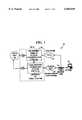
- FIG. 1is a block diagram illustrating a cable modem system with telephony return
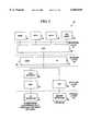
- FIG. 2is a block diagram illustrating a protocol stack for a cable modem
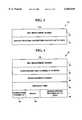
- FIG. 3is a block diagram illustrating a Telephony Channel Descriptor message structure
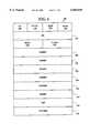
- FIG. 4is a block diagram illustrating a Termination System Information message structure
- FIG. 5is a flow diagram illustrating a method for addressing hosts in a cable modem system
- FIG. 6is a block diagram illustrating a Dynamic Host Configuration Protocol message structure
- FIGS. 7A and 7Bare a flow diagram illustrating a method for discovering hosts in a cable modem system
- FIG. 8is a block diagram illustrating a data-over-cable system for the method illustrated in FIGS. 7A and 7B;
- FIG. 9is a block diagram illustrating the message flow of the method illustrated in FIGS. 7A and 7B;
- FIGS. 10A and 10Bare a flow diagram illustrating a method for resolving host addresses in a data-over-cable system
- FIG. 11is a flow diagram illustrating a method for resolving discovered host addresses.
- FIG. 12is a block diagram illustrating the message flow of the method illustrated in FIG. 10;
- FIGS. 13A and 13Bare a flow diagram illustrating a method for obtaining addresses for customer premise equipment
- FIGS. 14A and 14Bare a flow diagram illustrating a method for resolving addresses for customer premise equipment
- FIGS. 15A and 15Bare a flow diagram illustrating a method for addressing network host interfaces from customer premise equipment
- FIGS. 16A and 16Bare a flow diagram illustrating a method for resolving network host interfaces from customer premise equipment.
- FIG. 17is a block diagram illustrating a message flow for the methods in FIGS. 15A, 15B, and 16A and 16B.
- FIG. 1is a block diagram illustrating a data-over-cable system with telephony return 10, hereinafter data-over-cable system 10.
- data-over-cable system 10Most cable providers known in the art predominately provide uni-directional cable systems, supporting only a "downstream" data path.
- a downstream data pathis the flow of data from a cable television network "headend" to customer premise equipment (e.g., a customer's personal computer).
- customer premise equipmente.g., a customer's personal computer
- a cable television network headendis a central location that is responsible for sending cable signals in a downstream direction.
- a return path via a telephony network (“telephony return”)is typically used for an "upstream" data path in uni-directional cable systems.
- An upstream data pathis the flow of data from customer premise equipment back to the cable television network headend.
- data-over-cable system 10 of the present inventionmay also provide a bi-directional data path (i.e., both downstream and upstream) without telephony return as is also illustrated in FIG. 1 and the present invention is not limited to a data-over-cable system with telephony return.
- customer premise equipment or cable modemhas an upstream connection to the cable modem termination system via a cable television connection, a wireless connection, a satellite connection, or a connection via other technologies to send data upstream to the cable modem termination system.
- Data-over-cable system 10includes a Cable Modem Termination System ("CMTS") 12 connected to a cable television network 14, hereinafter cable network 14.
- Cable network 14includes cable television networks such as those provided by Comcast Cable Communications, Inc., of Philadelphia, Pa., Cox Communications, or Atlanta, Ga., Tele-Communications, Inc., of Englewood Colo., Time-Warner Cable, of Marietta, Ga., Continental Cablevision, Inc., of Boston, Mass., and others. Cable network 14 is connected to a Cable Modem (“CM”) 16 with a downstream cable connection.
- CMCable Modem
- CM 16is connected to Customer Premise Equipment (“CPE”) 18 such as a personal computer system via a Cable Modem-to-CPE Interface (“CMCI”) 20.
- CPECustomer Premise Equipment
- CMCICable Modem-to-CPE Interface
- PSTN 22includes those public switched telephone networks provided by AT&T, Regional Bell Operating Companies (e.g., Ameritch, U.S. West, Bell Atlantic, Southern Bell Communications, Bell South, NYNEX, and Pacific Telesis Group), GTE, and others.
- the upstream telephony connectionis any of a standard telephone line connection, Integrated Services Digital Network (“ISDN”) connection, Asymmetric Digital Subscriber Line (“ADSL”) connection, or other telephony connection.
- ISDNIntegrated Services Digital Network
- ADSLAsymmetric Digital Subscriber Line
- PSTN 22is connected to a Telephony Remote Access Concentrator ("TRAC") 24.
- CM 16has an upstream connection to CMTS 12 via a cable television connection, a wireless connection, a satellite connection, or a connection via other technologies to send data upstream outside of the telephony return path.
- An upstream cable television connection via cable network 14is illustrated in FIG. 1.
- FIG. 1illustrates a telephony modem integral to CM 16.
- the telephony modemis a separate modem unit external to CM 16 used specifically for connecting with PSTN 22.
- a separate telephony modemincludes a connection to CM 16 for exchanging data.
- CM 16includes cable modems provided by the 3Com Corporation of Santa Clara, Calif., U.S. Robotics Corporation of Skokie, Ill., and others.
- CM 16includes functionality to connect only to cable network 14 and receives downstream signals from cable network 14 and sends upstream signals to cable network 14 without telephony return.
- the present inventionis not limited to cable modems used with telephony return.
- CMTS 12 and TRAC 24may be at a "headend" of cable system 10, or TRAC 24 may be located elsewhere and have routing associations to CMTS 12. CMTS 12 and TRAC 24 together are called a "Telephony Return Termination System" ("TRTS") 26.
- TRTS 26is illustrated by a dashed box in FIG. 1. CMTS 12 and TRAC 24 make up TRTS 26 whether or not they are located at the headend of cable network 14, and TRAC 24 may in located in a different geographic location from CMTS 12. Content severs, operations servers, administrative servers and maintenance servers used in data-over-cable system 10 (not shown in FIG. 1) may also be in different locations.
- Access points to data-over-cable system 10are connected to one or more CMTS's 12 or cable headend access points.
- Such configurationsmay be "one-to-one”, “one-to-many,” or “many-to-many,” and may be interconnected to other Local Area Networks ("LANs”) or Wide Area Networks (“WANs").
- LANsLocal Area Networks
- WANsWide Area Networks
- TRAC 24is connected to a data network 28 (e.g., the Internet or an intranet) by a TRAC-Network System Interface 30 ("TRAC-NSI").
- CMTS 12is connected to data network 28 by a CMTS-Network System Interface (“CMTS-NSI”) 32.
- CMTS-NSICMTS-Network System Interface
- the present inventionis not limited to data-over-cable system 10 illustrated in FIG. 1, and more or fewer components, connections and interfaces could also be used.
- FIG. 2is a block diagram illustrating a protocol stack 36 for CM 16.
- FIG. 2illustrates the downstream and upstream protocols used in CM 16.
- OSIOpen System Interconnection
- the OSI modelconsists of seven layers including from lowest-to-highest, a physical, data-link, network, transport, session, application and presentation layer.
- the physical layertransmits bits over a communication link.
- the data link layertransmits error free frames of data.
- the network layertransmits and routes data packets.
- CM 16is connected to cable network 14 in a physical layer 38 via a Radio Frequency (“RF") Interface 40.
- RF Interface 40has an operation frequency range of 50 Mega-Hertz ("MHz") to 1 Giga-Hertz (“GHz”) and a channel bandwidth of 6 MHz.
- MHzMega-Hertz
- GHzGiga-Hertz
- RF interface 40uses a signal modulation method of Quadrature Amplitude Modulation ("QAM").
- QAMQuadrature Amplitude Modulation
- QAMis used as a means of encoding digital information over radio, wire, or fiber optic transmission links.
- QAMis a combination of amplitude and phase modulation and is an extension of multiphase phase-shift-keying.
- QAMcan have any number of discrete digital levels typically including 4, 16, 64 or 256 levels. In one embodiment of the present invention, QAM-64 is used in RF interface 40. However, other operating frequencies modulation methods could also be used.
- IEEEInstitute of Electrical and Electronic Engineers
- IEEE standardscan be found on the World Wide Web at the Universal Resource Locator ("URL") "www.ieee.org.”
- URLUniversal Resource Locator
- MCNSMultimedia Cable Network Systems
- MAC layer 44controls access to a transmission medium via physical layer 38.
- MAC layer protocol 44see IEEE 802.14 for cable modems.
- other MAC layer protocols 44could also be used and the present invention is not limited to IEEE 802.14 MAC layer protocols (e.g., MCNS MAC layer protocols and others could also be used).
- Link security protocol stack 46prevents authorized users from making a data connection from cable network 14.
- RF interface 40 and MAC layer 44can also be used for an upstream connection if data-over-cable system 10 is used without telephony return.
- CM 16For upstream data transmission with telephony return, CM 16 is connected to PSTN 22 in physical layer 38 via modem interface 48.
- the International Telecommunications Union-Telecommunication Standardization Sector(“ITU-T”, formerly known as the CCITT) defines standards for communication devices identified by "V.xx” series where "xx” is an identifying number. ITU-T standards can be found on the World Wide Web at the URL "www.itu.ch.”
- ITU-T V.34is used as modem interface 48.
- ITU-T V.34is commonly used in the data link layer for modem communications and currently allows data rates as high as 33,600 bits-per-second ("bps"). For more information see the ITU-T V.34 standard. However, other modem interfaces or other telephony interfaces could also be used.
- PPPPoint-to-Point Protocol
- IETFInternet Engineering Task Force
- RFC-1661RFC-1662
- RFC-1663incorporated herein by reference.
- Information for IETF RFCscan be found on the World Wide Web at URLs "ds.internic.net” or "www.ietf.org.”
- IP layer 54Above both the downstream and upstream protocol layers in a network layer 52 is an Internet Protocol ("IP”) layer 54.
- IP layer 54hereinafter IP 54, roughly corresponds to OSI layer 3, the network layer, but is typically not defined as part of the OSI model.
- IP 54is a routing protocol designed to route traffic within a network or between networks. For more information on IP 54 see RFC-791 incorporated herein by reference.
- ICMP layer 56is used for network management.
- UDP layer 60Above IP 54 and ICMP 56 is a transport layer 58 with User Datagram Protocol layer 60 ("UDP").
- UDP layer 60hereinafter UDP 60, roughly corresponds to OSI layer 4, the transport layer, but is typically not defined as part of the OSI model. As is known in the art, UDP 60 provides a connectionless mode of communications with datagrams. For more information on UDP 60 see RFC-768 incorporated herein by reference.
- SNMP layer 62is used to support network management functions. For more information on SNMP layer 62 see RFC-1157 incorporated herein by reference.
- TFTP layer 64is a file transfer protocol used to download files and configuration information.
- DHCP layer 66is a protocol for passing configuration information to hosts on an IP 54 network. For more information on DHCP layer 66 see RFC-1541 incorporated herein by reference.
- UDP manager 68distinguishes and routes packets to an appropriate service (e.g., a virtual tunnel). More or few protocol layers could also be used with data-over-cable system 10.
- CM 16supports transmission and reception of IP 54 datagrams as specified by RFC-791.
- CMTS 12 and TRAC 24may perform filtering of IP 54 datagrams.
- CM 16is configurable for IP 54 datagram filtering to restrict CM 16 and CPE 18 to the use of only their assigned IP 54 addresses.
- CM 16is configurable for IP 54 datagram UDP 60 port filtering (i.e., deep filtering).
- CM 16forwards IP 54 datagrams destined to an IP 54 unicast address across cable network 14 or PSTN 22.
- Some routershave security features intended to filter out invalid users who alter or masquerade packets as if sent from a valid user. Since routing policy is under the control of network operators, such filtering is a vendor specific implementation. For example, dedicated interfaces (i.e., Frame Relay) may exist between TRAC 24 and CMTS 12 which preclude filtering, or various forms of virtual tunneling and reverse virtual tunneling could be used to virtually source upstream packets from CM 16.
- L2TPLevel 2 Tunneling Protocol
- PPTPPoint-to-Point Tunneling Protocol
- CM 16also forwards IP 54 datagrams destined to an IP 54 multicast address across cable network 14 or PSTN 22.
- CM 16is configurable to keep IP 54 multicast routing tables and to use group membership protocols.
- CM 16is also capable of IP 54 tunneling upstream through the telephony path.
- a CM 16 that wants to send a multicast packet across a virtual tunnelwill prepend another IP 54 header, set the destination address in the new header to be the unicast address of CMTS 12 at the other end of the tunnel, and set the IP 54 protocol field to be four, which means the next protocol is IP 54.
- CMTS 12 at the other end of the virtual tunnelreceives the packet, strips off the encapsulating IP 54 header, and forwards the packet as appropriate.
- a broadcast IP 54 capabilityis dependent upon the configuration of the direct linkage, if any, between TRAC 24 and CMTS 12.
- CMTS 12, CM 16, and TRAC 24are capable of routing IP 54 datagrams destined to an IP 54 broadcast address which is across cable network 14 or PSTN 22 if so configured.
- CM 16is configurable for IP 54 broadcast datagram filtering.
- An operating environment for CM 16 of the present inventionincludes a processing system with at least one high speed Central Processing Unit (“CPU”) and a memory system.
- CPUCentral Processing Unit
- CM 16includes a processing system with at least one high speed Central Processing Unit (“CPU") and a memory system.
- CPUCentral Processing Unit
- FIG. 16An operating environment for CM 16 of the present invention includes a processing system with at least one high speed Central Processing Unit (“CPU”) and a memory system.
- CPUCentral Processing Unit
- memory systemIn accordance with the practices of persons skilled in the art of computer programming, the present invention is described below with reference to acts and symbolic representations of operations that are performed by the processing system, unless indicated otherwise. Such acts and operations are sometimes referred to as being “computer-executed", or "CPU executed.”
- the acts and symbolically represented operationsinclude the manipulation of electrical signals by the CPU.
- the electrical systemrepresent data bits which cause a resulting transformation or reduction of the electrical signal representation, and the maintenance of data bits at memory locations in the memory system to thereby reconfigure or otherwise alter the CPU's operation, as well as other processing of signals.
- the memory locations where data bits are maintainedare physical locations that have particular electrical, magnetic, optical, or organic properties corresponding to the data bits.
- the data bitsmay also be maintained on a computer readable medium including magnetic disks, optical disks, organic disks, and any other volatile or non-volatile mass storage system readable by the CPU.
- the computer readable mediumincludes cooperating or interconnected computer readable media, which exist exclusively on the processing system or is distributed among multiple interconnected processing systems that may be local or remote to the processing system.
- CM 16When CM 16 is initially powered on, if telephony return is being used, CM 16 will receive a Telephony Channel Descriptor ("TCD") from CMTS 12 that is used to provide dialing and access instructions on downstream channels via cable network 14. Information in the TCD is used by CM 16 to connect to TRAC 24.
- TCDTelephony Channel Descriptor
- the TCDis transmitted as a MAC management message with a management type value of TRI -- TCD at a periodic interval (e.g., every 2 seconds).
- the TCD message parametersare encoded in a Type/Length/Value ("TLV”) form.
- TLVType/Length/Value
- SPDs 74are compound TLV encodings that define telephony physical-layer characteristics that are used by CM 16 to initiate a telephone call.
- SPD 74is a TLV-encoded data structure that contains sets of dialing and access parameters for CM 16 with telephony return.
- SPD 74is contained within TCD message 70. There may be multiple SPD 74 encodings within a single TCD message 70. There is at least one SPD 74 in TCD message 70.
- SPD 74 parametersare encoded as SPD-TLV tuples. SPD 74 contains the parameters shown in Table 1 and may contain optional vendor specific parameters. However, more or fewer parameters could also be used in SPD 74.
- a Termination System Information (“TSI”) messageis transmitted by CMTS 12 at periodic intervals (e.g., every 2 seconds) to report CMTS 12 information to CM 16 whether or not telephony return is used.
- the TSI messageis transmitted as a MAC 44 management message.
- the TSIprovides a CMTS 12 boot record in a downstream channel to CM 16 via cable network 14. Information in the TSI is used by CM 16 to obtain information about the status of CMTS 12.
- the TSI messagehas a MAC 44 management type value of TRI -- TSI.
- FIG. 4is a block diagram of a TSI message structure 76.
- TSI message structure 76includes a MAC 44 management header 78, a downstream channel IP address 80, a registration IP address 82, a CMTS 12 boot time 84, a downstream channel identifier 86, an epoch time 88 and vendor specific TLV encoded data 90.
- TSI message 76A description of the fields of TSI message 76 are shown in Table 2. However, more or fewer fields could also be used in TSI message 76.
- CM 16After receiving TCD 70 message and TSI message 76, CM 16 continues to establish access to data network 28 (and resources on the network) by first dialing into TRAC 24 and establishing a telephony PPP 50 session. Upon the completion of a successful PPP 50 connection, CM 16 performs PPP Link Control Protocol ("LCP") negotiation with TRAC 24. Once LCP negotiation is complete, CM 16 requests Internet Protocol Control Protocol ("IPCP”) address negotiation. For more information on IPCP see RFC-1332 incorporated herein by reference. During IPCP negotiation, CM 16 negotiates an IP 54 address with TRAC 24 for sending IP 54 data packet responses back to data network 28 via TRAC 24.
- LCPPPP Link Control Protocol
- IPCPInternet Protocol Control Protocol
- CM 16When CM 16 has established an IP 54 link to TRAC 24, it begins "upstream" communications to CMTS 12 via DHCP layer 66 to complete a virtual data connection by attempting to discover network host interfaces available on CMTS 12 (e.g., IP 54 host interfaces for a virtual IP 54 connection).
- the virtual data connectionallows CM 16 to receive data from data network 28 via CMTS 12 and cable network 14, and send return data to data network 28 via TRAC 24 and PSTN 22.
- CM 16must first determine an address of a host interface (e.g., an IP 54 interface) available on CMTS 12 that can be used by data network 28 to send data to CM 16.
- CM 16has only a downstream connection from CMTS 12 and has to obtain a connection address to data network 28 using an upstream connection to TRAC 24.
- FIG. 5is a flow diagram illustrating a method 92 for addressing network host interfaces in a data-over-cable system with telephony return via a cable modem.
- Method 92allows a cable modem to establish a virtual data connection to a data network.
- multiple network devicesare connected to a first network with a downstream connection of a first connection type, and connected to a second network with an upstream connection of a second connection type.
- the first and second networksare connected to a third network with a third connection type.
- a selection inputis received on a first network device from the first network over the downstream connection.
- the selection inputincludes a first connection address allowing the first network device to communicate with the first network via upstream connection to the second network.
- a first message of a first type for a first protocolis created on the first network device having the first connection address from the selection input in a first message field.
- the first messageis used to request a network host interface address on the first network.
- the first connection addressallows the first network device to have the first message with the first message type forwarded to network host interfaces available on the first network via the upstream connection to the second network.
- the first network devicesends the first message over the upstream connection to the second network.
- the second networkuses the first address field in the first message to forward the first message to one or more network host interfaces available on first network at step 100.
- Network host interfaces available on the first networkthat can provide the services requested in first message send a second message with a second message type with a second connection address in a second message field to the first network at step 102.
- the second connection addressallows the first network device to receive data packets from the third network via a network host interface available on the first network.
- the first networkforwards one or more second messages on the downstream connection to the first network device at step 104.
- the first network deviceselects a second connection address from one of the second messages from one of the one or more network host interfaces available on the first network at step 106 and establishes a virtual connection from the third network to the first network device using the second connection address for the selected network host interface.
- the virtual connectionincludes receiving data on the first network host interface on the first network from the third network and sending the data over the downstream connection to the first network device.
- the first network devicesends data responses back to the third network over the upstream connection to the second network, which forwards the data to the appropriate destination on the third network.
- the data-over-cable systemis data-over-cable system 10
- the first network deviceis CM 16
- the first networkis cable television network 14
- the downstream connectionis a cable television connection.
- the second networkis PSTN 22
- the upstream connectionis a telephony connection
- the third networkis data network 28 (e.g., the Internet or an intranet)
- the third type of connectionis an IP 54 connection.
- the first and second connection addressesare IP 54 addresses.
- Method 92allows CM 16 to determine an IP 54 network host interface address available on CMTS 12 to receive IP 54 data packets from data network 28, thereby establishing a virtual IP 54 connection with data network 28.
- CM 16may send data upstream back through cable network 14 (e.g., CM 16 to cable network 14 to CMTS 12) and not use PSTN 22 and the telephony return upstream path.
- CM 16includes a Dynamic Host Configuration Protocol ("DHCP") layer 66, hereinafter DHCP 66.
- DHCP 66is used to provide configuration parameters to hosts on a network (e.g., an IP 54 network).
- DHCP 66consists of two components: a protocol for delivering host-specific configuration parameters from a DHCP 66 server to a host and a mechanism for allocation of network host addresses to hosts.
- DHCP 66is built on a client-server model, where designated DHCP 66 servers allocate network host addresses and deliver configuration parameters to dynamically configured network host clients.
- FIG. 6is a block diagram illustrating a DHCP 66 message structure 108.
- the format of DHCP 66 messagesis based on the format of BOOTstrap Protocol ("BOOTP") messages described in RFC-951 and RFC-1542 incorporated herein by reference.
- BOOTPBOOTstrap Protocol
- DHCP 66is an extension of the BOOTP mechanism. This behavior allows existing BOOTP clients to interoperate with DHCP 66 servers without requiring any change to network host the clients' BOOTP initialization software.
- DHCP 66provides persistent storage of network parameters for network host clients.
- DHCP 66uses a BOOTP message format. Using BOOTP relaying agents eliminates the necessity of having a DHCP 66 server on each physical network segment.
- DHCP 66 message structure 108includes an operation code field 110 ("op"), a hardware address type field 112 ("htype"), a hardware address length field 114 ("hlen”), a number of hops field 116 (“hops”), a transaction identifier field 118 ("xid”), a seconds elapsed time field 120 (“secs”), a flags field 122 ("flags”), a client IP address field 124 (“ciaddr"), a your IP address field 126 (“yiaddr”), a server IP address field 128 (“siaddr”), a gateway/relay agent IP address field 130 (“giaddr”), a client hardware address field 132 (“chaddr”), an optional server name field 134 ("sname”), a boot file name 136 (“file”) and an optional parameters field 138 (“options”). Descriptions for DHCP 66 message 108 fields are shown in Table 4.
- the DHCP 66 message structure shown in FIG. 6is used to discover IP 54 and other network host interfaces in data-over-cable system 10.
- a network host cliente.g., CM 16
- Table 5illustrates a typical use of the DHCP 66 protocol to discover a network host interface from a network host client.
- CM 16has only a downstream connection from CMTS 12, which includes DHCP 66 servers, associated with network host interfaces available on CMTS 12.
- CM 16discovers network host interfaces via TRAC 24 and PSTN 22 on an upstream connection.
- CMTS 12has DHCP 66 servers associated with network host interfaces (e.g., IP interfaces), but CM 16 only has as downstream connection from CMTS 12.
- CM 16has an upstream connection to TRAC 24, which has a DHCP 66 layer.
- TRAC 24does not have DHCP 66 servers, or direct access to network host interfaces on CMTS 12.
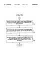
- FIGS. 7A and 7Bare a flow diagram illustrating a method 140 for discovering network host interfaces in data-over-cable system 10.
- CM 16When CM 16 has established an IP 54 link to TRAC 24, it begins communications with CMTS 12 via DHCP 66 to complete a virtual IP 54 connection with data network 28.
- CM 16has to communicate with CMTS 12 via PSTN 22 and TRAC 24 since CM 16 only has a "downstream" cable channel from CMTS 12.
- CM 16After receiving a TSI message 76 from CMTS 12 on a downstream connection, CM 16 generates a DHCP discover ("DHCPDISCOVER") message and sends it upstream via PSTN 22 to TRAC 22 to discover what IP 54 interfaces are available on CMTS 12.
- DHCPDISCOVERa DHCP discover
- the fields of the DHCP discover messageare set as illustrated in Table 6. However, other field settings may also be used.
- DHCP 66 giaddr-field 130(FIG. 6) includes the downstream channel IP address 80 of CMTS 12 obtained in TSI message 76 (e.g., the first message field from step 96 of method 92). Using the downstream channel IP address 80 of CMTS 12 obtained in TSI message 76 allows the DHCPDISCOVER message to be forwarded by TRAC 24 to DHCP 66 servers (i.e., protocol servers) associated with network host interfaces available on CMTS 12. If DHCP 66 giaddr-field 130 (FIG.
- the DHCP 66 serversends any return messages to a DHCP 66 server port on a DHCP 66 relaying agent (e.g., CMTS 12) whose address appears in DHCP 66 giaddr-field 130.
- a DHCP 66 relaying agente.g., CMTS 12
- the DHCP 66 giaddr-field 130is set to zero. If DHCP 66 giaddr-field 130 is zero, the DHCP 66 client is on the same subnet as the DHCP 66 server, and the DHCP 66 server sends any return messages to either the DHCP 66 client's network address, if that address was supplied in DHCP 66 ciaddr-field 124 (FIG. 6), or to a client's hardware address specified in DHCP 66 chaddr-field 132 (FIG. 6) or to a local subnet broadcast address (e.g., 255.255.255.255).
- a DHCP 66 layer on TRAC 24broadcasts the DHCPDISCOVER message on its local network leaving DHCP 66 giaddr-field 130 intact since it already contains a non-zero value.
- TRAC's 24 local networkincludes connections to one or more DHCP 66 proxies (i.e., network host interface proxies).
- the DHCP 66 proxiesaccept DHCP 66 messages originally from CM 16 destined for DHCP 66 servers connected to network host interfaces available on CMTS 12 since TRAC 24 has no direct access to DCHP 66 servers associated with network host interfaces available on CMTS 12.
- DHCP 66 proxiesare not used in a typical DHCP 66 discovery process.
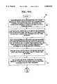
- One or more DHCP 66 proxies on TRAC's 24 local networkrecognizes the DHCPDISCOVER message and forwards it to one or more DHCP 66 servers associated with network host interfaces (e.g., IP 54 interfaces) available on CMTS 12 at step 146. Since DHCP 66 giaddr-field 130 (FIG. 6) in the DHCPDISCOVER message sent by CM 16 is already non-zero (i.e., contains the downstream IP address of CMTS 12), the DHCP 66 proxies also leave DHCP 66 giaddr-field 130 intact.
- network host interfacese.g., IP 54 interfaces
- One or more DHCP 66 servers for network host interfaces(e.g., IP 54 interfaces) available on CMTS 12 receive the DHCPDISCOVER message and generate a DHCP 66 offer message ("DHCPOFFER") at step 148.
- the DHCP 66 offer messageis an offer of configuration parameters sent from network host interfaces to DHCP 66 servers and back to a network host client (e.g., CM 16) in response to a DHCPDISCOVER message.
- the DHCP 66 offer messageis sent with the message fields set as illustrated in Table 7. However, other field settings can also be used.
- DHCP 66 yiaddr-field 126(e.g., second message field from step 102 of method 92) contains an IP 54 address for a network host interface available on CMTS 12 and used for receiving data packets from data network 28.
- DHCP 66 serverssend the DHCPOFFER message to the address specified in 66 giaddr-field 130 (i.e., CMTS 12) from the DHCPDISCOVER message if associated network host interfaces (e.g., IP 54 interfaces) can offer the requested service (e.g., IP 54 service) to CM 16.
- the DHCPDISOVER message DHCP 66 giaddr-field 130contains a downstream channel IP address 80 of CMTS 12 that was received by CM 16 in TSI message 76. This allows CMTS 12 to receive the DHCPOFFER messages from the DHCP 66 servers and send them to CM 16 via a downstream channel on cable network 14.
- CMTS 12receives one or more DHCPOFFER messages from one or more DHCP 66 servers associated with the network host interfaces (e.g., IP 54 interfaces).
- CMTS 12examines DHCP 66 yiaddr-field 126 and DHCP 66 chaddr-field 132 in the DHCPOFFER messages and sends the DHCPOFFER messages to CM 16 via cable network 14.
- DHCP 66 yiaddr-field 126contains an IP 54 address for a network host IP 54 interface available on CMTS 12 and used for receiving IP 54 data packets from data network 28.
- DHCP 66 chaddr-field 132contains the MAC 44 layer address for CM 16 on a downstream cable channel from CMTS 12 via cable network 14.
- CMTS 12knows the location of CM 16 since it sent CM 16 a MAC 44 layer address in one or more initialization messages (e.g., TSI message 76).
- CMTS 12sends the DHCPOFFER messages to a broadcast IP 54 address (e.g., 255.255.255.255) instead of the address specified in DHCP 66 yiaddr-field 126.
- DHCP 66 chaddr-field 132is still used to determine that MAC 44 layer address. If the BROADCAST bit in DHCP 66 flags field 122 is set, CMTS 12 does not update internal address or routing tables based upon DHCP 66 yiaddr-field 126 and DHCP 66 chaddr-field 132 pair when a broadcast message is sent.
- CM 16receives one or more DHCPOFFER messages from CMTS 12 via cable network 14 on a downstream connection.
- CM 16selects an offer for IP 54 service from one of the network host interfaces (e.g., an IP interfaces 54) available on CMTS 12 that responded to the DHCPDISOVER message sent at step 142 in FIG. 7A and establishes a virtual IP 54 connection.
- the selected DHCPOFFER messagecontains a network host interface address (e.g., IP 54 address) in DHCP 66 yiaddr-field 126 (FIG. 6).
- a cable modemacknowledges the selected network host interface with DHCP 66 message sequence explained below.
- CM 16After selecting and acknowledging a network host interface, CM 16 has discovered an IP 54 interface address available on CMTS 12 for completing a virtual IP 54 connection with data network 28. Acknowledging a network host interface is explained below.
- the virtual IP 54 connectionallows IP 54 data from data network 28 to be sent to CMTS 12 which forwards the IP 54 packets to CM 16 on a downstream channel via cable network 14.
- CM 16sends response IP 54 packets back to data network 28 via PSTN 22 and TRAC 24.
- FIG. 8is a block diagram illustrating a data-over-cable system 156 for the method illustrated in FIGS. 7A and 7B.
- Data-over-cable system 156includes DHCP 66 proxies 158, DHCP 66 servers 160 and associated Network Host Interfaces 162 available on CMTS 12. Multiple DHCP 66 proxies 158, DHCP 66 servers 160 and network host interfaces 162 are illustrated as single boxes in FIG. 8.
- FIG. 8also illustrates DHCP 66 proxies 158 separate from TRAC 24.
- TRAC 24includes DHCP 66 proxy functionality and no separate DHCP 66 proxies 158 are used. In such an embodiment, TRAC 24 forwards DHCP 66 messages using DHCP 66 giaddr-field 130 to DHCP 66 servers 160 available on CMTS 12.
- FIG. 9is a block diagram illustrating a message flow 162 of method 140 (FIGS. 7A and 7B).
- Message flow 162includes DHCP proxies 158 and DHCP servers 160 illustrated in FIG. 8 Steps 142, 144, 146, 148, 150 and 154 of method 140 (FIGS. 7A and 7B) are illustrated in FIG. 9.
- DHCP proxies 158are not separate entities, but are included in TRAC 24. In such an embodiment, DHCP proxy services are provided directly by TRAC 24.
- FIGS. 10A and 10Bare a flow diagram illustrating a method 166 for resolving and acknowledging host addresses in a data-over-cable system.
- Method 166includes a first network device that is connected to a first network with a downstream connection of a first connection type, and connected to a second network with an upstream connection of a second connection type. The first and second networks are connected to a third network with a third connection type.
- the first network deviceis CM 16
- the first networkis cable network 14
- the second networkis PSTN 22
- the third networkis data network 28 (e.g., the Internet).
- the downstream connectionis a cable television connection
- the upstream connectionis a telephony connection
- the third connectionis an IP connection.
- one or more first messagesare received on the first network device from the first network on the downstream connection at step 168.
- the one or more first messagesarc offers from one or more network host interfaces available on the first network to provide the first network device a connection to the third network.
- the first network deviceselects one of the network host interfaces using message fields in one of the one or more first messages at step 170.
- the first network devicecreates a second message with a second message type to accept the offered services from a selected network host interface at step 172.
- the second messageincludes a connection address for the first network in a first message field and an identifier to identify the selected network host interface in a second message field.
- the first network devicesends the second message over the upstream connection to the second network at step 174.
- the second networkuses the first message field in the second message to forward the second message to the one or more network host interfaces available on first network at step 176.
- a network host interface available on the first network identified in second message field in the second message from the first network devicerecognizes an identifier for the network host interface at 178 in FIG. 10B.
- the selected network host interfacesends a third message with a third message type to the first network at step 180.
- the third messageis an acknowledgment for the first network device that the selected network host interface received the second message from the first network device.
- the first networkstores a connection address for the selected network interface in one or more tables on the first network at step 182.
- the first networkwill forward data from the third network to the first network device when it is received on the selected network host interface using the connection address in the one or more routing tables.
- the first networkforwards the third message to the first network device on the downstream connection at step 184.
- the first network devicereceives the third message at step 186.
- the first network and the first network devicehave the necessary addresses for a virtual connection that allows data to be sent from the third network to a network host interface on the first network, and from the first network over the downstream connection to the first network device.
- Method 166accomplishes resolving network interface hosts addresses from a cable modem in a data-over-cable with telephony return.
- Method 166 of the present inventionis used in data-over-cable system 10 with telephony return.
- the present inventionis not limited to data-over-cable system 10 with telephony return and can be used in data-over-cable system 10 without telephony return by using an upstream cable channel instead of an upstream telephony channel.
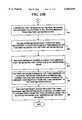
- FIGS. 11A and 11Bare a flow diagram illustrating a method 188 for resolving 20 discovered host addresses in data-over-cable system 10 with telephony return.
- CM 16receives one or more DHCPOFFER messages from one or more DHCP 66 servers associated with one or more network host interfaces (e.g., at step 168 in method 166).
- the one or more DHCPOFFER messagesinclude DHCP 66 fields set as illustrated in Table 7 above. However, other field settings could also be used.
- CM 16selects one of the DHCPOFFER messages (see also, step 170 in method 166).
- CM 16creates a DHCP 66 request message ("DHCPREQUEST") message to request the services offered by a network host interface selected at step 192.
- DHCPREQUESTa DHCP 66 request message
- the fields of the DHCP request messageare set as illustrated in Table 8. However, other field settings may also be used.
- the DHCPREQUEST messageis used to "request" services from the selected IP 54 host interface available on CMTS 12 using a DHCP 66 server associated with the selected network host interface.
- DHCP 66 giaddr-field 130(FIG. 6) includes the downstream channel IP address 80 for CMTS 12 obtained in TSI message 76 (e.g., the first message-field from step 172 of method 166). Putting the downstream channel IP address 80 obtained in TSI message 76 allows the DHCPREQUEST message to be forwarded by TRAC 24 to DCHP 66 servers associated with network host interfaces available on CMTS 12.
- DHCP 66 giaddr-field 126contains an identifier (second message field, step 172 in method 166)
- DHCP 66 sname-field 134contains a DHCP 66 server identifier associated with the selected network host interface.
- a DHCP 66 serversends any return messages to a DHCP 66 server port on a DHCP 66 relaying agent (e.g., CMTS 12) whose address appears in DHCP 66 giaddr-field 130.
- a DHCP 66 relaying agente.g., CMTS 12
- DHCP 66 giaddr-field 130If DHCP 66 giaddr-field 130 is zero, the DHCP 66 client is on the same subnet as the DHCP 66 server, and the DHCP 66 server sends any return messages to either the DHCP 66 client's network address, if that address was supplied in DHCP 66 ciaddr-field 124, or to the client's hardware address specified in DHCP 66 chaddr-field 132 or to the local subnet broadcast address.
- CM 16sends the DHCPREQUEST message on the upstream connection to TRAC 24 via PSTN 22.
- a DHCP 66 layer on TRAC 24broadcasts the DHCPREQUEST message on its local network leaving DHCP 66 giaddr-field 130 intact since it already contains a non-zero value.
- TRAC's 24 local networkincludes connections to one or more DHCP 66 proxies.
- the DHCP 66 proxiesaccept DHCP 66 messages originally from CM 16 destined for DHCP 66 servers associated with network host interfaces available on CMTS 12.
- TRAC 24provides the DHCP 66 proxy functionality, and no separate DHCP 66 proxies are used.
- the one or more DHCP 66 proxies on TRAC's 24 local network messageforwards the DHCPOFFER to one or more of the DHCP 66 servers associated with network host interfaces (e.g., IP 54 interfaces) available on CMTS 12 at step 200 in FIG. 11B. Since DHCP 66 giaddr-field 130 in the DHCPDISCOVER message sent by CM 16 is already non-zero (i.e., contains the downstream IP address of CMTS 12), the DHCP 66 proxies leave DHCP 66 giaddr-field 130 intact.
- network host interfacese.g., IP 54 interfaces
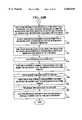
- One or more DHCP 66 servers for the selected network host interfaces (e.g., IP 54 interface) available on CMTS 12receives the DHCPOFFER message at step 202.
- a selected DHCP 66 serverrecognizes a DHCP 66 server identifier in DHCP 66 sname-field 134 or the IP 54 address that was sent in the DCHPOFFER message in the DHCP 66 yiaddr-field 126 from the DHCPREQUST message as being for the selected DHCP 66 server.
- the selected DHCP 66 server associated with network host interface selected by CM 16 in the DHCPREQUEST messagecreates and sends a DCHP 66 acknowledgment message ("DHCPACK") to CMTS 12 at step 204.
- DHCPACKDCHP 66 acknowledgment message
- the DHCPACK messageis sent with the message fields set as illustrated in Table 9. However, other field settings can also be used.
- DHCP 66 yiaddr-fieldagain contains the IP 54 address for the selected network host interface available on CMTS 12 for receiving data packets from data network 28.
- the selected DHCP 66 serversends the DHCACK message to the address specified in DHCP 66 giaddr-field 130 from the DHCPREQUEST message to CM 16 to verify the selected network host interface (e.g., IP 54 interface) will offer the requested service (e.g., IP 54 service).
- the selected network host interfacee.g., IP 54 interface
- CMTS 12receives the DHCPACK message from the selected DHCP 66 server associated with the selected network host interface IP 54 address(e.g., IP 54 interface).
- CMTS 12examines DHCP 66 yiaddr-field 126 and DHCP 66 chaddr-field 132 in the DHCPOFFER messages.
- DHCP 66 yiaddr-field 126contains an IP 54 address for a network host IP 54 interface available on CMTS 12 and used for receiving IP 54 data packets from data network 28 for CM 16.
- DHCP 66 chaddr-field 132contains the MAC 44 layer address for CM 16 on a downstream cable channel from CMTS 12 via cable network 14.
- CMTS 12updates an Address Resolution Protocol ("ARP") table and other routing tables on CMTS 12 to reflect the addresses in DHCP 66 yiaddr-field 126 and DHCP 66 chaddr-field 132 at step 208.
- ARPAddress Resolution Protocol
- CMTS 12updates an Address Resolution Protocol (“ARP") table and other routing tables on CMTS 12 to reflect the addresses in DHCP 66 yiaddr-field 126 and DHCP 66 chaddr-field 132 at step 208.
- ARPallows a gateway such as CMTS 12 to forward any datagrams from a data network such as data network 28 it receives for hosts such as CM 16.
- ARPis defined in RFC-826, incorporated herein by reference.
- CMTS 12stores a pair of network address values in the ARP table, the IP 54 address of the selected network host interface from DHCP 66 yiaddr-field 126 and a Network Point of Attachment ("NPA") address.
- NPANetwork Point of Attachment
- the NPA addressis a MAC 44 layer address for CM 16 via a downstream cable channel.
- the IP/NPA address pairare stored in local routing tables with the IP/NPA addresses of hosts (e.g., CMs 16) that are attached to cable network 14.
- CMTS 12sends the DHCPACK message to CM 16 via cable network 14.
- CM 16receives the DHCPACK message, and along with CMTS 12 has addresses for a virtual connection between data network 28 and CM 16.
- a NPAi.e., MAC 44 address
- CMTS 12sends the DHCPACK messages to a broadcast IP 54 address (e.g., 255.255.255.255).
- DHCP 66 chaddr-field 132is still used to determine that MAC layer address. If the BROADCAST bit in flags field 122 is set, CMTS 12 does not update the ARP table or offer routing tables based upon DHCP 66 yiaddr-field 126 and DHCP 66 chaddr-field 132 pair when a broadcast message is sent.
- FIG. 12is a block diagram illustrating the message flow 214 of the method 188 illustrated in FIGS. 11A and 11B.
- Message flow 214includes DHCP proxies 158 and DHCP servers 160 illustrated in FIG. 8.
- Method steps 194, 196, 198, 204, 208, 210 and 212 of method 188are illustrated in FIG. 12.
- DHCP proxies 158are not separate entities, but are included in TRAC 24. In such an embodiment, DHCP proxy services are provided directly by TRAC 24.
- CMTS 12has a valid IP/MAC address pair in one or more address routing tables including an ARP table to forward IP 54 data packets from data network 28 to CM 16, thereby creating a virtual IP 54 data path to/from CM 16 as was illustrated in method 92 (FIG. 5) and Table 3.
- CM 16has necessary parameters to proceed to the next phase of initialization, a download of a configuration file via TFTP 64. Once CM 16 has received the configuration file and has been initialized, it registers with CMTS 12 and is ready to receive data from data network 14.
- CM 16may generate a DHCP 66 decline message ("DHCPDECLINE") and transmit it to TRAC 24 via PSTN 22.
- DHCPDECLINEDHCP 66 decline message
- a DHCP 66 layer in TRAC 24forwards the DHCPDECLINE message to CMTS 12.
- CMTS 12flushes its ARP tables and routing tables to remove the now invalid IP/MAC pairing.
- CM 16uses the IP 54 address it receives in the DHCPACK message as the IP 54 address of the selected network host interface for receiving data from data network 28.
- Method 188can also be used with a cable modem that has a two-way connection (i.e., upstream and downstream) to cable network 14 and CMTS 12.
- CM 16would broadcast the DHCPREQUEST message to one or more DHCP 66 servers associated with one or more network host interfaces available on CMTS 12 using an upstream connection on data network 14 including the IP 54 address of CMTS 12 in DHCP 66 giaddr-field 130.
- Method 188accomplishes resolving addresses for network interface hosts from a cable modem in a data-over-cable with or without telephony return, and without extensions to the existing DHCP protocol.
- CPE 18also uses DHCP 66 to generate requests to obtain IP 54 addresses to allow CPE 18 to also receive data from data network 28 via CM 16.
- CM 16functions as a standard BOOTP relay agent/DHCP Proxy 158 to facilitate CPE's 18 access to DHCP 66 server 160.
- FIGS. 13A and 13Bare a flow diagram illustrating a method 216 for obtaining addresses for customer premise equipment.
- CM 16 and CMTS 12use information from method 214 to construct IP 54 routing and ARP table entries for network host interfaces 162 providing data to CMCI 20 and to CPE 18.
- Method 216 in FIGS. 13A and 13Bincludes a data-over-cable system with telephony return and first network device with a second network device for connecting the first network device to a first network with a downstream connection of a first connection type, and for connecting to a second network with an upstream connection of a second connection type.
- the first and second networksare connected to a third network with a third connection type.
- data-over-cable system with telephony returnis data-over-cable system 10 with the first network device CPE 18 and the second network device CM 16.
- the first networkis cable television network 14, the downstream connection is a cable television connection, the second network is PSTN 22, the upstream connection is a telephony connection, the third network is data network 28 (e.g., the Internet or an intranet) and the third type of connection is an IP 54 connection.
- the present inventionis not limited to the network components described and other network components may also be used.
- Method 216allows CPE 18 to determine an IP 54 network host interface address available on CMTS 12 to receive IP 54 data packets from data network 54, thereby establishing a virtual IP 54 connection with data network 28 via CM 16.
- a first message of a first type(e.g., a DHCP 66 discover message) with a first message field for a first connection is created on the first network device.
- the first messageis used to discover a network host interface address on the first network to allow a virtual connection to the third network.
- the first network devicesends the first message to the second network device.
- the second network devicechecks the first message field at step 222. If the first message field is zero, the second network device puts its own connection address into the first message field at step 224.
- the second network device connection addressallows the messages from network host interfaces on the first network to return messages to the second network device attached to the first network device. If the first message field is non-zero, the second network device does not alter the first message field since there could be a relay agent attached to the first network device that may set the first connection address field.
- the second network deviceforwards the first message to a connection address over the upstream connection to the second network.
- the connection addressis an IP broadcast address (e.g., 255.255.255.255).
- IP broadcast addresse.g., 255.255.255.255.255.
- the second networkuses the first connection address in the first message field in the first message to forward the first message to one or more network host interfaces (e.g., IP 54 network host interfaces) available on first network at step 228.
- network host interfacese.g., IP 54 network host interfaces
- One or more network host interfaces available on the first network that can provide the services requested in first messagesend a second message with a second message type with a second connection address in a second message field to the first network at step 230 in FIG. 13B.
- the second connection addressallows the first network device to receive data packets from the third network via a network host interface on the first network.
- the first networkforwards the one or more second messages on the downstream connection to the second network device at step 232.
- the second network deviceforwards the one or more second messages to the first network device at step 234.
- the first network deviceselects one of the one or more network host interfaces on the first network using the one or more second messages at step 236. This allows a virtual connection to be established between the third network and the first network device via the selected network host interface on the first network and the second network device.
- FIGS. 14A and 14Bare a flow diagram illustrating a method 240 for resolving addresses for the network host interface selected by a first network device to create a virtual connection to the third network.
- one or more second messagesare received with a second message type on the first network device from the second network device from the first network on a downstream connection at step 242.
- the one or more second messagesare offers from one or more protocol servers associated with one or more network host interfaces available on the first network to provide the first network device a connection to the third network.
- the first network deviceselects one of the network host interfaces using one of the one or more second messages at step 244.
- the first network devicecreates a third message with a third message type to accept the offered services from the selected network host interface at step 246.
- the third messageincludes a connection address for the first network in a first message field and an identifier to identify the selected network host interface in a second message field.
- first network device equipmentsends the third message to the second network device.
- the second network devicesends the third message over the upstream connection to the second network at step 250.
- the second networkuses the first message field in the third message to forward the third message to the one or more network host interfaces available on first network at step 252.
- a network host interface available on the first network identified in second message field in the third message from the first network devicerecognizes an identifier for the selected network host interface at step 254 in FIG. 14B.
- the selected network host interfacesends a fourth message with a fourth message type to the first network at step 256.
- the fourth messageis an acknowledgment for the first network device that the selected network host interface received the third message.
- the fourth messageincludes a second connection address in a third message field.
- the second connection addressis a connection address for the selected network host interface.
- the first networkstores the connection address for the selected network interface from the third message in one or more routing tables (e.g., an ARP table) on the first network at step 258.
- the first networkwill forward data from the third network to the first network device via the second network device when it is received on the selected network host interface using the connection address from the third message field.
- the first networkforwards the fourth message to the second network device on the downstream connection at step 260.
- the second network devicereceives the fourth message and stores the connection address from the third message field for the selected network interface in one or more routing tables on the second network device at step 262.
- the connection address for the selected network interfaceallows the second network device to forward data from the third network sent by the selected network interface to the customer premise equipment.
- the second network deviceforward the fourth message to the first network device.
- the first network deviceestablishes a virtual connection between the third network and the first network device.
- the first network, the second network device and the first network devicehave the necessary connection addresses for a virtual connection that allows data to be sent from the third network to a network host interface on the first network, and from the first network over the downstream connection to the second network and then to the first network device.
- method 240accomplishes resolving network interface hosts addresses from customer premise equipment with a cable modem in a data-over-cable with telephony return without extensions to the existing DHCP protocol.
- Methods 216 and 240 of the present inventionare used in data-over-cable system 10 with telephony return with CM 16 and CPE 18.
- the present inventionis not limited to data-over-cable system 10 with telephony return and can be used in data-over-cable system 10 without telephony return by using an upstream cable channel instead of an upstream telephony channel.
- FIGS. 15A and 15Bare a flow diagram illustrating a method 268 for addressing network host interfaces from CPE 18.
- CPE 18generates a DHCPDISCOVER message broadcasts the DHCPDISCOVER message on its local network with the fields set as illustrated in Table 6 above with addresses for CPE 18 instead of CM 16. However, more or fewer field could also be set.
- CM 16receives the DHCPDISCOVER as a standard BOOTP relay agent at step 272.
- the DHCP DISCOVER messagehas a MAC 44 layer address for CPE 18 in DHCP 66 chaddr-field 132, which CM 16 stores in one or more routing tables.
- the CM 16checks the DHCP 66 giaddr-field 130 (FIG. 6) at step 274. If DHCP 66 giaddr-field 130 is set to zero, CM 16 put its IP 54 address into DHCP 66 giaddr-field 130 at step 276.
- CM 16does not alter DHCP 66 giaddr-field 130 since there could be another BOOTP relay agent attached to CPE 18 which may have already set DHCP 66 giaddr-field 130. Any BOOTP relay agent attached to CPE 18 would have also have acquired its IP 54 address from using a DCHP 66 discovery process (e.g., FIG. 12).
- CM 16broadcasts the DHCPDISCOVER message to a broadcast address via PSTN 22 to TRAC 24.
- the broadcast addressis an IP 54 broadcast address (e.g., 255.255.255.255).
- one or more DHCP 66 proxies 158 associated with TRAC 24recognize the DHCPDISOVER message, and forward it to one or more DHCP 66 servers 160 associated with one or more network host interfaces 162 available on CMTS 12. Since DHCP 66 giaddr-field 130 is already non-zero, the DHCP proxies leave DHCP 66 giaddr-field 130 intact.
- TRAC 24includes DCHP 66 proxy 158 functionality and no separate DHCP 66 proxies 158 are used.
- the one or more DHCP servers 160receive the DHCPDISCOVER message from one or more DHCP proxies, and generate one or more DHCPOFFER messages to offer connection services for one or more network host interfaces 162 available on CMTS 12 with the fields set as illustrated in Table 7.
- the one or more DHCP servers 160send the one or more DHCPOFFER messages to the address specified in DHCP 66 giaddr-field 130 (e.g., CM 16 or a BOOTP relay agent on CPE 18), which is an IP 54 address already contained in an ARP or other routing table in CMTS 12. Since CMTS 12 also functions as a relay agent for the one or more DHCP servers 160, the one or more DHCPOFFER messages are received on CMTS 12 at step 284.
- CMTS 12examines DHCP 66 yiaddr-field 126 and DHCP 66 giaddr-field 130 in the DHCPOFFER messages, and sends the DHCPOFFER messages down cable network 14 to IP 54 address specified in the giaddr-field 130.
- the MAC 44 address for CM 16is obtained through a look-up of the hardware address associated with DHCP 66 chaddr-field 130.
- CMTS 12sends the DHCPOFFER message to a broadcast IP 54 address (e.g., 255.255.255.255), instead of the address specified in DHCP 66 yiaddr-field 126 CMTS 12 does not update its ARP or other routing tables based upon the broadcast DCHP 66 yiaddr-field 126 DHCP 66 chaddr-field 132 address pair.
- a broadcast IP 54 addresse.g., 255.255.255.255
- CM 16receives the one or more DHCPOFFER messages and forwards them to CPE 18 at step 286.
- CM 16uses the MAC 44 address specified determined by DHCP 66 chaddr-field 132 look-up in its routing tables to find the address of CPE 18 even if the BROADCAST bit in DHCP 66 flags-field 122 is set.
- CPE 18receives the one or more DHCPOFFER messages from CM 16.
- CPE 18selects one of the DHCPOFFER messages to allow a virtual connection to be established between data network 28 and CPE 18.
- Method 266accomplishes addressing network interface hosts from CPE 18 in data-over-cable system 10 without extensions to the existing DHCP protocol.
- FIGS. 16A and 16Bare a flow diagram illustrating a method 294 for resolving network host interfaces from CPE 18.
- CPE 18receives the one or more DHCPOFFER messages from one or more DHCP 66 servers associated with one or more network host interface available on CMTS 12.
- CPE 18chooses one offer of services from a selected network host interface.
- CPE 18generates a DHCPREQUEST message with the fields set as illustrated in Table 8 above with addresses for CPE 18 instead of CM 16. However, more or fewer fields could also be set.
- CPE 18sends the DHCPREQUEST message to CM 16.
- CM 16forwards the message to TRAC 24 via PSTN 22.
- a DHCP 66 layer on TRAC 24broadcasts the DHCPREQUEST message on its local network leaving DHCP 66 giaddr-field 130 intact since it already contains a non-zero value.
- TRAC's 24 local networkincludes connections to one or more DHCP 66 proxies.
- the DHCP 66 proxiesaccept DHCP 66 messages originally from CPE 18 destined for DHCP 66 servers associated with network host interfaces available on CMTS 12.
- TRAC 24provides the DHCP 66 proxy functionality, and no separate DHCP 66 proxies are used.
- One or more DHCP 66 proxies on TRAC's 24 local networkrecognize the DHCPOFFER message and forward it to one or more of the DHCP 66 servers associated with network host interfaces (e.g., IP 54 interfaces) available on CMTS 12 at step 308 in FIG. 16B. Since DHCP 66 giaddr-field 130 in the DHCPDISCOVER message sent by CPE 18 is already non-zero, the DHCP 66 proxies leave DHCP 66 giaddr-field 130 intact.
- network host interfacese.g., IP 54 interfaces
- One or more DHCP 66 servers for the selected network host interfaces (e.g., IP 54 interface) available on CMTS 12receive the DHCPOFFER message at step 310.
- a selected DHCP 66 serverrecognizes a DHCP 66 server identifier in DHCP 66 sname-field 134 or the IP 54 address that was sent in the DCHPOFFER message in the DHCP 66 yiaddr-field 126 from the DHCPREQUST message for the selected DHCP 66 server.
- the selected DHCP 66 server associated with network host interface selected by CPE 18 in the DHCPREQUEST messagecreates and sends a DCHP acknowledgment message ("DHCPACK") to CMTS 12 at step 312 using the DHCP 66 giaddr-field 130.
- the DHCPACK messageis sent with the message fields set as illustrated in Table 9. However, other field settings can also be used.
- DHCP 66 yiaddr-fieldcontains the IP 54 address for the selected network host interface available on CMTS 12 for receiving data packets from data network 28 for CPE 18.
- CMTS 12receives the DHCPACK message.
- CMTS 12examines the DHCP 66 giaddr-field 130 and looks up that IP address in its ARP table for an associated MAC 44 address. This is a MAC 44 address for CM 16, which sent the DHCPREQUEST message from CPE 18.
- CMTS 12uses the MAC 44 address associated with the DHCP 66 giaddr-field 130 and the DHCP 66 yiaddr-field 126 to update its routing and ARP tables reflecting this address pairing at step 316.
- CMTS 12sends the DHCPACK message on a downstream channel on cable network 14 to the IP 54 and MAC 44 addresses, respectively (i.e., to CM 16).
- CMTS 12sends the DHCPACK message to a broadcast IP 54 address (e.g., 255.255.255.255), instead of the address specified in the DHCP 66 yiaddr-field 126 CMTS 12 uses the MAC 44 address associated with the DHCP 66 chaddr-field 130 even if the BROADCAST bit is set.
- a broadcast IP 54 addresse.g., 255.255.255.255
- CM 16receives the DHCPACK message. It examines the DHCP 66 yiaddr-field 126 and chaddr-field 132, and updates its routing table and an ARP routing table to reflect the address pairing at step 320. At step 322, CM 16 sends the DHCPACK message to CPE 18 via CMCI 20 at IP 54 and MAC 44 addresses respectively from its routing tables. If the BROADCAST bit in the DHCP 66 flags-field 122 is set to one, CM 16 sends the downstream packet to a broadcast IP 54 address (e.g., 255.255.255.255), instead of the address specified in DHCP 66 yiaddr-field 126.
- a broadcast IP 54 addresse.g., 255.255.255.255
- CM 16uses the MAC 44 address specified in DHCP 66 chaddr-field 132 even if the BROADCAST bit is set to located CPE 18.
- CPE 18receives the DHCPACK from CM 16 and has established a virtual connection to data network 28.
- CPE 18may generate a DHCP 66 decline (“DHCPDECLINE") message and send it to CM 16.
- CM 16will transmit the DHCPDECLINE message up the PPP 50 link via PSTN 22 to TRAC 24.
- TRAC 24sends a unicast copy of the message to CMTS 12.
- CM 16 and CMTS 12examine the DHCP 66 yiaddr-field 126 and giaddr-field 130, and update their routing and ARP tables to flush any invalid pairings.
- CM 16 CMTS 12Upon completion of methods 266 and 292, CM 16 CMTS 12 have valid IP/MAC address pairings in their routing and ARP tables. These tables store the same set of IP 54 addresses, but does not associate them with the same MAC 44 addresses. This is because CMTS 12 resolves all CPE 18 IP 54 addresses to the MAC 44 address of a corresponding CM 16. The CMs 16, on other hand, are able to address the respective MAC 44 addresses of their CPEs 18. This also allows DHCP 66 clients associated with CPE 18 to function normally since the addressing that is done in CM 16 and CMTS 12 is transparent to CPE 18 hosts.
- FIG. 17is a block diagram illustrating a message flow 326 for methods 268 and 294 in FIGS. 15A, 15B, and 16A and 16B.
- Message flow 326illustrates a message flow for methods 268 and 294, for a data-over-cable system with and without telephony return.
- CM 16forwards requests from CPE 18 via an upstream connection on cable network 14 to DHCP servers 160 associated with one or more network host interfaces available on CMTS 12.
- Method 268 and 294accomplishes resolving addresses for network interface hosts from customer premise equipment in a data-over-cable with or without telephony return without extensions to the existing DHCP protocol.
- Methods 268 and 294 of the present inventionare used in data-over-cable system 10 with telephony return.
- the present inventionis not limited to data-over-cable system 10 with telephony return and can be used in data-over-cable system 10 without telephony return by using an upstream cable channel instead of an upstream telephony channel.
Landscapes
- Engineering & Computer Science (AREA)
- Signal Processing (AREA)
- Computer Networks & Wireless Communication (AREA)
- Multimedia (AREA)
- Data Exchanges In Wide-Area Networks (AREA)
Abstract
Description
TABLE 1 ______________________________________SPD 74 Parameter Description ______________________________________ Factory Default Flag Boolean value, if TRUE(1), indicates a SPD which should be used byCM 16. Service Provider Name This parameter includes the name of a service provider. Format is standard ASCII string composed of numbers and letters. Telephone Numbers These parameters contain telephone numbers thatCM 16 uses to initiate a telephony modem link during a login process. Connections are attempted in ascending numeric order (i.e., Phone Number 1, Phone Number 2...). The SPD contains a valid telephony dial string as the primary dial string (Phone Number 1), secondary dial-strings are optional. Format is ASCII string(s) composed of: any sequence of numbers, pound "#" and star "*" keys and comma character "," used to indicate a two second pause in dialing. Connection Threshold The number of sequential connection failures before indicating connection failure. A dial attempt that does not result in an answer and connection after no more than ten rings is considered a failure. The default value is one. Login User Name This contains auser name CM 16 will use an authentication protocol over the telephone link during the initialization procedure. Format is a monolithic sequence of alphanumeric characters in an ASCII string composed of numbers and letters. Login Password This contains a password thatCM 16 will use during authentication over a telephone link during the initialization procedure. Format is a monolithic sequence of alphanumeric characters in an ASCII string composed of numbers and letters. DHCP Authenticate Boolean value, reserved to indicate thatCM 16 uses a specific indicatedDHCP 66 Server (see next parameter) for aDHCP 66 Client and BOOTP Relay Process when TRUE (one). The default is FALSE (zero) which allows anyDHCP 66 Server.DHCP Server IP 54 address value of aDHCP 66Server CM 16 uses forDHCP 66 Client and BOOTP Relay Process. If this attribute is present andDHCP 66 Authenticate attribute is TRUE(1). The default value is integer zero. RADIUS Realm The realm name is a string that defines a RADIUS server domain. Format is a monolithic sequence of alphanumeric characters in an ACSII string composed of numbers and letters. PPP Authentication This parameter instructs the telephone modem which authentication procedure to perform over the telephone link. Demand Dial Timer This parameter indicates time (in seconds) of inactive networking time that will be allowed to elapse before hanging up a telephone connection atCM 16. If this optional parameter is not present, or set to zero, then the demand dial feature is not activated. The default value is zero. Vendor Specific Extensions Optional vendor specific extensions. ______________________________________
TABLE 2 ______________________________________TSI 76 Parameter Description ______________________________________ Downstream Channel This field contains anIP 54 address ofIP Address 80CMTS 12 available on the downstream channel this message arrived on.Registration IP Address 82 This field contains anIP 54address CM 16 sends its registration request messages to. This address MAY be the same as theDownstream Channel IP 54 address.CMTS Boot Time 84 Specifies an absolute-time of aCMTS 12 recorded epoch. The clock setting for this epoch uses the current clock time with an unspecified accuracy. Time is represented as a 32 bit binary number. Downstream Channel ID 86 A downstream channel on which this message has been transmitted. This identifier is arbitrarily chosen byCMTS 12 and is unique within theMAC 44 layer.Epoch 88 An integer value that is incremented eachtime CMTS 12 is either re- initialized or performs address or routing table flush. VendorSpecific Extensions 90 Optional vendor extensions may be added as TLV encoded data. ______________________________________
TABLE 3 ______________________________________ 1. AnIP 54 datagram fromdata network 28 destined forCM 16 arrives on CMTS-NSI 32 and entersCMTS 12. 2.CMTS 12 encodes theIP 54 datagram in a cable data frame, passes it toMAC 44 and transmits it "downstream" toRF interface 40 onCM 16 viacable network 14. 3.CM 16 recognizes the encodedIP 54 datagram inMAC layer 44 received viaRF interface 40. 4.CM 16 responds to the cable data frame and encapsulates aresponse IP 54 datagram in aPPP 50 frame and transmits it "upstream" withmodem interface 48 viaPSTN 22 toTRAC 24. 5.TRAC 24 decodes theIP 54 datagram and forwards it via TRAC-NSI 30 to a destination ondata network 28. ______________________________________
TABLE 4 ______________________________________DCHP 66 ParameterDescription ______________________________________ OP 110 Message op code / message type. 1 BOOTREQUEST, 2 = BOOTREPLY.HTYPE 112 Hardware address type (e.g., `1` = 10 Mps Ethernet).HLEN 114 Hardware address length (e.g. `6` for 10 Mbps Ethernet).HOPS 116 Client sets to zero, optionally used by relay-agents when booting via a relay- agent.XID 118 Transaction ID, a random number chosen by the client, used by the client and server to associate messages and responses between a client and a server.SECS 120 Filled in by client, seconds elapsed since client started trying to boot.FLAGS 122 Flags including a BROADCAST bit.CIADDR 124 Client IP address; filled in by client in DHCPREQUEST if verifying previously allocated configuration parameters.YIADDR 126 `Your` (client) IP address.SIADDR 128IP 54 address of next server to use in bootstrap; returned in DHCPOFFER, DHCPACK and DHCPNAK by server.GIADDR 130 Gatewayrelay agent IP 54 address, used in booting via a relay-agent. CHADDR Client hardware address (e.g.,MAC 132layer 44 address).SNAME 134 Optional server host name, null terminated string.FILE 136 Boot file name, terminated by a null string. OPTIONS Optional parameters. 138 ______________________________________
TABLE 5 ______________________________________ 1. A network host client broadcasts aDHCP 66 discover message on its local physical subnet. TheDHCP 66 discover message may include options that suggest values for a network host interface address. BOOTP relay agents may pass the message on toDHCP 66 servers not on the same physical subnet. 2. DHCP servers may respond with a DHCPOFFER message that includes an available network address in the `yiaddr` field (and other configuration parameters inDHCP 66 options) from a network host interface.DHCP 66 servers unicasts the DHCPOFFER message to the network host client (using the DHCP/BOOTP relay agent if necessary) if possible, or may broadcast the message to a broadcast address (preferably 255.255.255.255) on the client's subnet. 3. The network host client receives one or more DHCPOFFER messages from one ormore DHCP 66 servers. The network host client may choose to wait for multiple responses. 4. The network host client chooses oneDHCP 66 server with an associated network host interface from which to request configuration parameters, based on the configuration parameters offered in the DHCPOFFER messages. ______________________________________
TABLE 6 ______________________________________DHCP 66 ParameterDescription ______________________________________ OP 110 Set to BOOTREQUEST.HTYPE 112 Set to network type (e.g., one for 10 Mbps Ethernet).HLEN 114 Set to network length (e.g., six for 10 Mbps Ethernet) HOPS 116 Set to zero.FLAGS 118 Set BROADCAST bit to zero.CIADDR 124If CM 16 has previously been assigned anIP 54 address, theIP 54 address is placed in this field. IfCM 16 has previously been assigned anIP 54 address byDHCP 66, and also has been assigned an address via IPCP,CM 16 places theDHCP 66IP 54 address in this field.GIADDR 130CM 16 places theDownstream Channel IP 54address 80 ofCMTS 12 obtained inTSI message 76 on a cable downstream channel in this field.CHADDR 132CM 16 places its 48-bit MAC 44 LAN address in this field. ______________________________________
TABLE 7 ______________________________________DHCP 66 Parameter Description ______________________________________ FLAGS 122 BROADCAST bit set to zero.YIADDR 126IP 54 address from a network host interface to allowCM 16 to receive data fromdata network 28 via a network host interface available onCMTS 12.SIADDR 128 AnIP 54 address for aTFTP 64 server to download configuration information for an interface host.CHADDR 132MAC 44 address ofCM 16.SNAME 134Optional DHCP 66 server identifier with an interface host. FILE 136 ATFTP 64 configuration file name forCM 16. ______________________________________
TABLE 8 ______________________________________DHCP 66 ParameterDescription ______________________________________ OP 110 Set to BOOTREQUEST.HTYPE 112 Set to network type (e.g., one for 10Mbps Ethernet).HLEN 114 Set to network length (e.g., six for 10Mbps Ethernet) HOPS 116 Set to zero.FLAGS 118 Set BROADCAST bit to zero.CIADDR 124If CM 16 has previously been assigned an IP address, the IP address is placed in this field. IfCM 16 has previously been assigned an IP address byDHCP 66, and also has been assigned an address via IPCP,CM 16 places theDHCP 66IP 54 address in this field.YIADDR 126IP 54 address sent from the selected network interface host inDCHPOFFER message GIADDR 130CM 16 places theDownstream Channel IP 54address 80CMTS 12 obtained inTSI message 76 on a cable downstream channel in this field.CHADDR 132CM 16 places its 48-bit MAC 44 LAN address in this field.SNAME 134DHCP 66 server identifier for the selected network interface host ______________________________________
TABLE 9 ______________________________________DHCP 66 Parameter Description ______________________________________ FLAGS 122 Set a BROADCAST bit to zero.YIADDR 126IP 54 address for the selected network host interface to allowCM 16 to receive data fromdata network 28.SIADDR 128 AnIP 54 address for aTFTP 64 server to download configuration information for an interface host.CHADDR 132MAC 44 address ofCM 16.SNAME 134DHCP 66 server identifier associated with the selected network host interface. FILE 136 A configuration file name for an network interface host. ______________________________________
Claims (27)
Priority Applications (1)
| Application Number | Priority Date | Filing Date | Title |
|---|---|---|---|
| US09/018,814US6065049A (en) | 1998-02-04 | 1998-02-04 | Method and system for resolving addresses for network host interfaces from a cable modem |
Applications Claiming Priority (1)
| Application Number | Priority Date | Filing Date | Title |
|---|---|---|---|
| US09/018,814US6065049A (en) | 1998-02-04 | 1998-02-04 | Method and system for resolving addresses for network host interfaces from a cable modem |
Publications (1)
| Publication Number | Publication Date |
|---|---|
| US6065049Atrue US6065049A (en) | 2000-05-16 |
Family
ID=21789902
Family Applications (1)
| Application Number | Title | Priority Date | Filing Date |
|---|---|---|---|
| US09/018,814Expired - LifetimeUS6065049A (en) | 1998-02-04 | 1998-02-04 | Method and system for resolving addresses for network host interfaces from a cable modem |
Country Status (1)
| Country | Link |
|---|---|
| US (1) | US6065049A (en) |
Cited By (69)
| Publication number | Priority date | Publication date | Assignee | Title |
|---|---|---|---|---|
| US6178455B1 (en) | 1997-01-17 | 2001-01-23 | Scientific-Atlanta, Inc. | Router which dynamically requests a set of logical network addresses and assigns addresses in the set to hosts connected to the router |
| US6230203B1 (en) | 1995-10-20 | 2001-05-08 | Scientific-Atlanta, Inc. | System and method for providing statistics for flexible billing in a cable environment |
| US6272150B1 (en) | 1997-01-17 | 2001-08-07 | Scientific-Atlanta, Inc. | Cable modem map display for network management of a cable data delivery system |
| US6275853B1 (en) | 1998-05-27 | 2001-08-14 | 3Com Corporation | System and method for extending communications features using generic management information base objects |
| US6286058B1 (en) | 1997-04-14 | 2001-09-04 | Scientific-Atlanta, Inc. | Apparatus and methods for automatically rerouting packets in the event of a link failure |
| US20010036199A1 (en)* | 2000-03-30 | 2001-11-01 | Terry John B. | Architecture and method for automatic distributed gain control for modem communications over passive multipoint networks |
| US6331987B1 (en) | 1998-05-27 | 2001-12-18 | 3Com Corporation | Method and system for bundling data in a data-over-cable system |
| US20020021711A1 (en)* | 1999-10-27 | 2002-02-21 | Gummalla Ajay Chandra V. | System and method for suppressing silence in voice traffic over an asynchronous communication medium |
| US6351773B1 (en) | 1998-12-21 | 2002-02-26 | 3Com Corporation | Methods for restricting access of network devices to subscription services in a data-over-cable system |
| US6370147B1 (en) | 1998-04-23 | 2002-04-09 | 3Com Corporation | Method for addressing of passive network hosts in a data-over-cable system |
| US20020059634A1 (en)* | 1999-01-13 | 2002-05-16 | Coaxmedia,Inc | Capacity scaling and functional element redistribution within an in-building coax cable internet Access system |
| US6404861B1 (en) | 1999-10-25 | 2002-06-11 | E-Cell Technologies | DSL modem with management capability |
| US20020078445A1 (en)* | 2000-07-11 | 2002-06-20 | Imran Sharif | Internet appliance for interactive audio/video display using a remote control unit for user input |
| US20020101620A1 (en)* | 2000-07-11 | 2002-08-01 | Imran Sharif | Fax-compatible Internet appliance |
| US20020101883A1 (en)* | 2000-11-30 | 2002-08-01 | Ruszczyk Chester A. | Method for reducing interference from initializing network devices in a data-over-cable system |
| US20020112051A1 (en)* | 2000-12-15 | 2002-08-15 | International Business Machines Corporation | Method and system for network management with redundant monitoring and categorization of endpoints |
| US20020116720A1 (en)* | 1999-01-13 | 2002-08-22 | Coaxmedia, Inc. | Multi-band coax extender for in-building digital communication systems |
| US6442158B1 (en) | 1998-05-27 | 2002-08-27 | 3Com Corporation | Method and system for quality-of-service based data forwarding in a data-over-cable system |
| US6467091B1 (en) | 1995-10-20 | 2002-10-15 | Scientific-Atlanta, Inc. | Constant bit rate transport in a contention based medium access control |
| US6484317B1 (en) | 1996-04-26 | 2002-11-19 | Broadband Royalty Corporation | Method for routing data messages through a cable transmission system |
| US6490289B1 (en)* | 1998-11-03 | 2002-12-03 | Cisco Technology, Inc. | Multiple network connections from a single PPP link with network address translation |
| US6490290B1 (en) | 1998-12-30 | 2002-12-03 | Cisco Technology, Inc. | Default internet traffic and transparent passthrough |
| US20030009528A1 (en)* | 2001-07-08 | 2003-01-09 | Imran Sharif | System and method for using an internet appliance to send/receive digital content files as E-mail attachments |
| US6510162B1 (en) | 1998-05-27 | 2003-01-21 | 3Com Corporation | System and method for managing channel usage in a data over cable system |
| US6560203B1 (en) | 1998-05-27 | 2003-05-06 | 3Com Corporation | Method for changing type-of-service in a data-over-cable system |
| US20030103615A1 (en)* | 2001-12-04 | 2003-06-05 | Wolfgang Baltes | Method to eliminate user setup for installation of broadband modems, routers, and integrated modem-routers |
| US6577642B1 (en) | 1999-01-15 | 2003-06-10 | 3Com Corporation | Method and system for virtual network administration with a data-over cable system |
| US20030115167A1 (en)* | 2000-07-11 | 2003-06-19 | Imran Sharif | Web browser implemented in an Internet appliance |
| US6621859B1 (en)* | 1998-02-11 | 2003-09-16 | Globespanvirata, Inc. | Combined cable/DSL modem and method for high speed data communication |
| US20030191845A1 (en)* | 2002-04-03 | 2003-10-09 | Hinds John Sherman | Method, apparatus and system for establishing communications between communications devices |
| US6636485B1 (en) | 1998-05-14 | 2003-10-21 | 3Com Corporation | Method and system for providing quality-of-service in a data-over-cable system |
| US6654387B1 (en) | 1999-05-21 | 2003-11-25 | 3Com Corporation | Method for network address table maintenance in a data-over-cable system using a network device registration procedure |
| US6657991B1 (en) | 1998-12-21 | 2003-12-02 | 3Com Corporation | Method and system for provisioning network addresses in a data-over-cable system |
| US6662135B1 (en) | 1998-12-09 | 2003-12-09 | 3Com Corporation | Method and apparatus for reflective mixer testing of a cable modem |
| US6697862B1 (en) | 1999-05-21 | 2004-02-24 | 3Com Corporation | System and method for network address maintenance using dynamic host configuration protocol messages in a data-over-cable system |
| US6711132B2 (en) | 2000-12-15 | 2004-03-23 | General Instrument Corporation | Method and apparatus for reducing end-to-end delay when providing internet telephony over a CATV cable network |
| US20040107284A1 (en)* | 1996-04-03 | 2004-06-03 | Francis Koperda | System and method for providing statistics for flexible billing in a cable environment |
| US6754622B1 (en) | 1999-05-24 | 2004-06-22 | 3Com Corporation | Method for network address table maintenance in a data-over-cable system using destination reachibility |
| US6771614B1 (en)* | 1999-07-06 | 2004-08-03 | Cisco Technology, Inc. | Wireless power control in conjunction with a wireline MAC protocol |
| US6775276B1 (en) | 1998-05-27 | 2004-08-10 | 3Com Corporation | Method and system for seamless address allocation in a data-over-cable system |
| US6785292B1 (en) | 1999-05-28 | 2004-08-31 | 3Com Corporation | Method for detecting radio frequency impairments in a data-over-cable system |
| US6804262B1 (en) | 2000-04-28 | 2004-10-12 | 3Com Corporation | Method and apparatus for channel determination through power measurements |
| US6816500B1 (en) | 2000-07-10 | 2004-11-09 | 3Com Corporation | Apparatus, method and system for multimedia access network channel management |
| US6944881B1 (en) | 2000-06-19 | 2005-09-13 | 3Com Corporation | Method for using an initial maintenance opportunity for non-contention ranging |
| US6948184B1 (en) | 2000-11-30 | 2005-09-20 | 3Com Corporation | System and method for calibrating power level during initial ranging of a network client device |
| US6952428B1 (en) | 2001-01-26 | 2005-10-04 | 3Com Corporation | System and method for a specialized dynamic host configuration protocol proxy in a data-over-cable network |
| US6985437B1 (en) | 1999-05-25 | 2006-01-10 | 3Com Corporation | Method for dynamic performance optimization in a data-over-cable system |
| US6986157B1 (en) | 1998-12-21 | 2006-01-10 | 3Com Corporation | Method and system for dynamic service registration in a data-over-cable system |
| US7068597B1 (en) | 2000-11-27 | 2006-06-27 | 3Com Corporation | System and method for automatic load balancing in a data-over-cable network |
| US7072337B1 (en) | 2002-01-25 | 2006-07-04 | 3Com Corporation | System and method for resolving network addresses for network devices on distributed network subnets |
| US7073055B1 (en) | 2001-02-22 | 2006-07-04 | 3Com Corporation | System and method for providing distributed and dynamic network services for remote access server users |
| US7085306B1 (en) | 2001-10-30 | 2006-08-01 | 3Com Corporation | System and method for a multi-frequency upstream channel in a computer network |
| US7089580B1 (en) | 2000-03-29 | 2006-08-08 | 3Com Corporation | Method for improved cable modem ranging in a data-over-cable system |
| US7088678B1 (en) | 2001-08-27 | 2006-08-08 | 3Com Corporation | System and method for traffic shaping based on generalized congestion and flow control |
| US7099338B1 (en) | 1999-02-27 | 2006-08-29 | 3Com Corporation | System and method for insuring dynamic host configuration protocol operation by a host connected to a data network |
| US7107326B1 (en) | 2000-10-13 | 2006-09-12 | 3Com Corporation | Method and system for integrating IP address reservations with policy provisioning |
| US20060203786A1 (en)* | 2004-06-17 | 2006-09-14 | Srinivas Kola | Cable-TV-based wireless network |
| US20060248464A1 (en)* | 2005-04-27 | 2006-11-02 | Comcast Cable Holdings, Llc | Method and system of transporting media signals and allocating assets |
| US7203954B1 (en) | 2000-10-11 | 2007-04-10 | Sony Corporation | IP address discovery for cable modem in set-top box |
| US7222255B1 (en) | 2001-02-28 | 2007-05-22 | 3Com Corporation | System and method for network performance testing |
| US7245291B2 (en) | 2000-07-11 | 2007-07-17 | Imran Sharif | System and method for internet appliance data entry and navigation |
| CN100380902C (en)* | 2000-09-29 | 2008-04-09 | 西门子公司 | Method for connection of data terminal devices to data network |
| US7443865B1 (en) | 2002-04-04 | 2008-10-28 | Cisco Technology, Inc. | Multiple network connections from a single PPP link with network address translation |
| US7792092B1 (en)* | 1998-12-29 | 2010-09-07 | Nokia Corporation | Data transmission method and a network element |
| US8843643B2 (en) | 1998-10-30 | 2014-09-23 | Virnetx, Inc. | System and method employing an agile network protocol for secure communications using secure domain names |
| US8874771B2 (en) | 1998-10-30 | 2014-10-28 | Virnetx, Inc. | Agile network protocol for secure communications with assured system availability |
| US8943201B2 (en) | 1998-10-30 | 2015-01-27 | Virnetx, Inc. | Method for establishing encrypted channel |
| US9860283B2 (en) | 1998-10-30 | 2018-01-02 | Virnetx, Inc. | Agile network protocol for secure video communications with assured system availability |
| US10511573B2 (en) | 1998-10-30 | 2019-12-17 | Virnetx, Inc. | Agile network protocol for secure communications using secure domain names |
Citations (26)
| Publication number | Priority date | Publication date | Assignee | Title |
|---|---|---|---|---|
| US5014234A (en)* | 1986-08-25 | 1991-05-07 | Ncr Corporation | System with software usage timer and counter for allowing limited use but preventing continued unauthorized use of protected software |
| US5138712A (en)* | 1989-10-02 | 1992-08-11 | Sun Microsystems, Inc. | Apparatus and method for licensing software on a network of computers |
| US5347304A (en)* | 1991-09-10 | 1994-09-13 | Hybrid Networks, Inc. | Remote link adapter for use in TV broadcast data transmission system |
| US5442749A (en)* | 1991-08-22 | 1995-08-15 | Sun Microsystems, Inc. | Network video server system receiving requests from clients for specific formatted data through a default channel and establishing communication through separate control and data channels |
| US5488412A (en)* | 1994-03-31 | 1996-01-30 | At&T Corp. | Customer premises equipment receives high-speed downstream data over a cable television system and transmits lower speed upstream signaling on a separate channel |
| US5489897A (en)* | 1992-04-15 | 1996-02-06 | Fujitsu Limited | Power control monitoring system for underwater cable communications systems |
| US5586121A (en)* | 1995-04-21 | 1996-12-17 | Hybrid Networks, Inc. | Asymmetric hybrid access system and method |
| US5608446A (en)* | 1994-03-31 | 1997-03-04 | Lucent Technologies Inc. | Apparatus and method for combining high bandwidth and low bandwidth data transfer |
| US5623601A (en)* | 1994-11-18 | 1997-04-22 | Milkway Networks Corporation | Apparatus and method for providing a secure gateway for communication and data exchanges between networks |
| US5675732A (en)* | 1995-05-08 | 1997-10-07 | Lucent Technologies Inc. | Dynamic channel assignment for TCP/IP data transmitted via cable television channels by managing the channels as a single sub network |
| US5710885A (en)* | 1995-11-28 | 1998-01-20 | Ncr Corporation | Network management system with improved node discovery and monitoring |
| US5761602A (en)* | 1995-09-13 | 1998-06-02 | Wagner Dsp Technologies | Hybrid multichannel data transmission system utilizing a broadcast medium |
| US5778181A (en)* | 1996-03-08 | 1998-07-07 | Actv, Inc. | Enhanced video programming system and method for incorporating and displaying retrieved integrated internet information segments |
| US5790548A (en)* | 1996-04-18 | 1998-08-04 | Bell Atlantic Network Services, Inc. | Universal access multimedia data network |
| US5790677A (en)* | 1995-06-29 | 1998-08-04 | Microsoft Corporation | System and method for secure electronic commerce transactions |
| US5790198A (en)* | 1990-09-10 | 1998-08-04 | Starsight Telecast, Inc. | Television schedule information transmission and utilization system and process |
| US5799086A (en)* | 1994-01-13 | 1998-08-25 | Certco Llc | Enhanced cryptographic system and method with key escrow feature |
| US5805804A (en)* | 1994-11-21 | 1998-09-08 | Oracle Corporation | Method and apparatus for scalable, high bandwidth storage retrieval and transportation of multimedia data on a network |
| US5819042A (en)* | 1996-02-20 | 1998-10-06 | Compaq Computer Corporation | Method and apparatus for guided configuration of unconfigured network and internetwork devices |
| US5854901A (en)* | 1996-07-23 | 1998-12-29 | Cisco Systems, Inc. | Method and apparatus for serverless internet protocol address discovery using source address of broadcast or unicast packet |
| US5864679A (en)* | 1993-09-06 | 1999-01-26 | Kabushiki Kaisha Toshiba | Transaction routing in a multiple processor system using an extracted transaction feature parameter and transaction historical data |
| US5870134A (en)* | 1997-03-04 | 1999-02-09 | Com21, Inc. | CATV network and cable modem system having a wireless return path |
| US5872523A (en)* | 1996-03-12 | 1999-02-16 | Motorola, Inc. | Target device and method for establishing a communication path in a networked communications system |
| US5923659A (en)* | 1996-09-20 | 1999-07-13 | Bell Atlantic Network Services, Inc. | Telecommunications network |
| US5922049A (en)* | 1996-12-09 | 1999-07-13 | Sun Microsystems, Inc. | Method for using DHCP and marking to override learned IP addesseses in a network |
| US5958007A (en)* | 1997-05-13 | 1999-09-28 | Phase Three Logic, Inc. | Automatic and secure system for remote access to electronic mail and the internet |
- 1998
- 1998-02-04USUS09/018,814patent/US6065049A/ennot_activeExpired - Lifetime
Patent Citations (29)
| Publication number | Priority date | Publication date | Assignee | Title |
|---|---|---|---|---|
| US5014234A (en)* | 1986-08-25 | 1991-05-07 | Ncr Corporation | System with software usage timer and counter for allowing limited use but preventing continued unauthorized use of protected software |
| US5138712A (en)* | 1989-10-02 | 1992-08-11 | Sun Microsystems, Inc. | Apparatus and method for licensing software on a network of computers |
| US5790198A (en)* | 1990-09-10 | 1998-08-04 | Starsight Telecast, Inc. | Television schedule information transmission and utilization system and process |
| US5442749A (en)* | 1991-08-22 | 1995-08-15 | Sun Microsystems, Inc. | Network video server system receiving requests from clients for specific formatted data through a default channel and establishing communication through separate control and data channels |
| US5347304A (en)* | 1991-09-10 | 1994-09-13 | Hybrid Networks, Inc. | Remote link adapter for use in TV broadcast data transmission system |
| US5489897A (en)* | 1992-04-15 | 1996-02-06 | Fujitsu Limited | Power control monitoring system for underwater cable communications systems |
| US5864679A (en)* | 1993-09-06 | 1999-01-26 | Kabushiki Kaisha Toshiba | Transaction routing in a multiple processor system using an extracted transaction feature parameter and transaction historical data |
| US5799086A (en)* | 1994-01-13 | 1998-08-25 | Certco Llc | Enhanced cryptographic system and method with key escrow feature |
| US5488412A (en)* | 1994-03-31 | 1996-01-30 | At&T Corp. | Customer premises equipment receives high-speed downstream data over a cable television system and transmits lower speed upstream signaling on a separate channel |
| US5608446A (en)* | 1994-03-31 | 1997-03-04 | Lucent Technologies Inc. | Apparatus and method for combining high bandwidth and low bandwidth data transfer |
| US5623601A (en)* | 1994-11-18 | 1997-04-22 | Milkway Networks Corporation | Apparatus and method for providing a secure gateway for communication and data exchanges between networks |
| US5805804A (en)* | 1994-11-21 | 1998-09-08 | Oracle Corporation | Method and apparatus for scalable, high bandwidth storage retrieval and transportation of multimedia data on a network |
| US5859852A (en)* | 1995-04-21 | 1999-01-12 | Hybrid Networks, Inc. | Hybrid access system with automated client-side configuration |
| US5828655A (en)* | 1995-04-21 | 1998-10-27 | Hybrid Networks, Inc. | Hybrid access system with quality-based channel switching |
| US5818845A (en)* | 1995-04-21 | 1998-10-06 | Hybrid Networks, Inc. | Hybrid access system having channel allocation and prioritized polling schemes |
| US5586121A (en)* | 1995-04-21 | 1996-12-17 | Hybrid Networks, Inc. | Asymmetric hybrid access system and method |
| US5675732A (en)* | 1995-05-08 | 1997-10-07 | Lucent Technologies Inc. | Dynamic channel assignment for TCP/IP data transmitted via cable television channels by managing the channels as a single sub network |
| US5790677A (en)* | 1995-06-29 | 1998-08-04 | Microsoft Corporation | System and method for secure electronic commerce transactions |
| US5761602A (en)* | 1995-09-13 | 1998-06-02 | Wagner Dsp Technologies | Hybrid multichannel data transmission system utilizing a broadcast medium |
| US5710885A (en)* | 1995-11-28 | 1998-01-20 | Ncr Corporation | Network management system with improved node discovery and monitoring |
| US5819042A (en)* | 1996-02-20 | 1998-10-06 | Compaq Computer Corporation | Method and apparatus for guided configuration of unconfigured network and internetwork devices |
| US5778181A (en)* | 1996-03-08 | 1998-07-07 | Actv, Inc. | Enhanced video programming system and method for incorporating and displaying retrieved integrated internet information segments |
| US5872523A (en)* | 1996-03-12 | 1999-02-16 | Motorola, Inc. | Target device and method for establishing a communication path in a networked communications system |
| US5790548A (en)* | 1996-04-18 | 1998-08-04 | Bell Atlantic Network Services, Inc. | Universal access multimedia data network |
| US5854901A (en)* | 1996-07-23 | 1998-12-29 | Cisco Systems, Inc. | Method and apparatus for serverless internet protocol address discovery using source address of broadcast or unicast packet |
| US5923659A (en)* | 1996-09-20 | 1999-07-13 | Bell Atlantic Network Services, Inc. | Telecommunications network |
| US5922049A (en)* | 1996-12-09 | 1999-07-13 | Sun Microsystems, Inc. | Method for using DHCP and marking to override learned IP addesseses in a network |
| US5870134A (en)* | 1997-03-04 | 1999-02-09 | Com21, Inc. | CATV network and cable modem system having a wireless return path |
| US5958007A (en)* | 1997-05-13 | 1999-09-28 | Phase Three Logic, Inc. | Automatic and secure system for remote access to electronic mail and the internet |
Non-Patent Citations (2)
| Title |
|---|
| S. Adiraju, J. Fijolek, IPCDN Telephony Return MIB, Internet Engineering Task Force, "IETF," Internet Draft, "<draft-ietf-ipcdn-tri-mib-00.1.txt>," Mar. 23, 1998, pp. 1 to 26. |
| S. Adiraju, J. Fijolek, IPCDN Telephony Return MIB, Internet Engineering Task Force, IETF, Internet Draft, draft ietf ipcdn tri mib 00.1.txt , Mar. 23, 1998, pp. 1 to 26.* |
Cited By (121)
| Publication number | Priority date | Publication date | Assignee | Title |
|---|---|---|---|---|
| USRE44211E1 (en) | 1995-10-20 | 2013-05-07 | Scientific-Atlanta, Llc | Constant bit rate transport in a contention based medium access control |
| US6230203B1 (en) | 1995-10-20 | 2001-05-08 | Scientific-Atlanta, Inc. | System and method for providing statistics for flexible billing in a cable environment |
| US6467091B1 (en) | 1995-10-20 | 2002-10-15 | Scientific-Atlanta, Inc. | Constant bit rate transport in a contention based medium access control |
| US20040107284A1 (en)* | 1996-04-03 | 2004-06-03 | Francis Koperda | System and method for providing statistics for flexible billing in a cable environment |
| US6983327B2 (en) | 1996-04-03 | 2006-01-03 | Scientific-Atlanta, Inc. | System and method for providing statistics for flexible billing in a cable environment |
| US7028088B1 (en) | 1996-04-03 | 2006-04-11 | Scientific-Atlanta, Inc. | System and method for providing statistics for flexible billing in a cable environment |
| US6484317B1 (en) | 1996-04-26 | 2002-11-19 | Broadband Royalty Corporation | Method for routing data messages through a cable transmission system |
| US6996836B2 (en) | 1996-04-26 | 2006-02-07 | Broadband Royalty Corporation | System and method for routing data messages through a cable transmission system |
| US20030126618A1 (en)* | 1996-04-26 | 2003-07-03 | Broadband Royalty Corporation | System and method for routing data messages through a cable transmission system |
| US8522265B2 (en) | 1997-01-17 | 2013-08-27 | Scott E. Hrastar | Modem apparatus for a cable data delivery system |
| US6178455B1 (en) | 1997-01-17 | 2001-01-23 | Scientific-Atlanta, Inc. | Router which dynamically requests a set of logical network addresses and assigns addresses in the set to hosts connected to the router |
| US20010050979A1 (en)* | 1997-01-17 | 2001-12-13 | Hrastar Scott E. | Two-tiered authorization and authentication for a cable data delivery system |
| US6529517B2 (en) | 1997-01-17 | 2003-03-04 | Scientific-Atlanta, Inc. | Router for which a logical network address which is not unique to the router is the gateway address in default routing table entries |
| US7099308B2 (en) | 1997-01-17 | 2006-08-29 | Scientific-Atlantic, Inc. | Router for use with a link that has a set of concurrent channels |
| US6301223B1 (en) | 1997-01-17 | 2001-10-09 | Scientific-Atlanta, Inc. | Method of using routing protocols to reroute packets during a link failure |
| US6519224B2 (en) | 1997-01-17 | 2003-02-11 | Scientific-Atlanta, Inc. | Method of using routing protocols to reroute packets during a link failure |
| US6208656B1 (en) | 1997-01-17 | 2001-03-27 | Scientific-Atlanta, Inc. | Methods for dynamically assigning link addresses and logical network addresses |
| US6405253B1 (en) | 1997-01-17 | 2002-06-11 | Scientific-Atlanta, Inc. | Dynamic allocation of a set of addresses to router RF modem for individual assignment to hosts |
| US6282208B1 (en) | 1997-01-17 | 2001-08-28 | Scientific-Atlanta, Inc. | Data traffic control in a data modem system |
| US6249523B1 (en) | 1997-01-17 | 2001-06-19 | Scientific-Atlanta, Inc. | Router for which a logical network address which is not unique to the gateway address in default routing table entries |
| US6618353B2 (en) | 1997-01-17 | 2003-09-09 | Scientific-Atlanta, Inc. | Router for use with a link that has a set of concurrent channels |
| US6922412B2 (en) | 1997-01-17 | 2005-07-26 | Scientific-Atlanta, Inc. | Methods for dynamically assigning link addresses and logical network addresses |
| US6324267B1 (en) | 1997-01-17 | 2001-11-27 | Scientific-Atlanta, Inc. | Two-tiered authorization and authentication for a cable data delivery system |
| US6272150B1 (en) | 1997-01-17 | 2001-08-07 | Scientific-Atlanta, Inc. | Cable modem map display for network management of a cable data delivery system |
| US6286058B1 (en) | 1997-04-14 | 2001-09-04 | Scientific-Atlanta, Inc. | Apparatus and methods for automatically rerouting packets in the event of a link failure |
| US6621859B1 (en)* | 1998-02-11 | 2003-09-16 | Globespanvirata, Inc. | Combined cable/DSL modem and method for high speed data communication |
| US6370147B1 (en) | 1998-04-23 | 2002-04-09 | 3Com Corporation | Method for addressing of passive network hosts in a data-over-cable system |
| US6636485B1 (en) | 1998-05-14 | 2003-10-21 | 3Com Corporation | Method and system for providing quality-of-service in a data-over-cable system |
| US6442158B1 (en) | 1998-05-27 | 2002-08-27 | 3Com Corporation | Method and system for quality-of-service based data forwarding in a data-over-cable system |
| US6775276B1 (en) | 1998-05-27 | 2004-08-10 | 3Com Corporation | Method and system for seamless address allocation in a data-over-cable system |
| US6275853B1 (en) | 1998-05-27 | 2001-08-14 | 3Com Corporation | System and method for extending communications features using generic management information base objects |
| US6510162B1 (en) | 1998-05-27 | 2003-01-21 | 3Com Corporation | System and method for managing channel usage in a data over cable system |
| US6331987B1 (en) | 1998-05-27 | 2001-12-18 | 3Com Corporation | Method and system for bundling data in a data-over-cable system |
| US6560203B1 (en) | 1998-05-27 | 2003-05-06 | 3Com Corporation | Method for changing type-of-service in a data-over-cable system |
| US9100375B2 (en) | 1998-10-30 | 2015-08-04 | Virnetx, Inc. | System and method employing an agile network protocol for secure communications using secure domain names |
| US9819649B2 (en) | 1998-10-30 | 2017-11-14 | Virnetx, Inc. | System and method employing an agile network protocol for secure communications using secure domain names |
| US10511573B2 (en) | 1998-10-30 | 2019-12-17 | Virnetx, Inc. | Agile network protocol for secure communications using secure domain names |
| US9374346B2 (en) | 1998-10-30 | 2016-06-21 | Virnetx, Inc. | Agile network protocol for secure communications using secure domain names |
| US9386000B2 (en) | 1998-10-30 | 2016-07-05 | Virnetx, Inc. | System and method for establishing a communication link |
| US10187387B2 (en) | 1998-10-30 | 2019-01-22 | Virnetx, Inc. | Method for establishing connection between devices |
| US9094399B2 (en) | 1998-10-30 | 2015-07-28 | Virnetx, Inc. | Method for establishing secure communication link between computers of virtual private network |
| US8904516B2 (en) | 1998-10-30 | 2014-12-02 | Virnetx, Inc. | System and method employing an agile network protocol for secure communications using secure domain names |
| US9967240B2 (en) | 1998-10-30 | 2018-05-08 | Virnetx, Inc. | Agile network protocol for secure communications using secure domain names |
| US8843643B2 (en) | 1998-10-30 | 2014-09-23 | Virnetx, Inc. | System and method employing an agile network protocol for secure communications using secure domain names |
| US9860283B2 (en) | 1998-10-30 | 2018-01-02 | Virnetx, Inc. | Agile network protocol for secure video communications with assured system availability |
| US8874771B2 (en) | 1998-10-30 | 2014-10-28 | Virnetx, Inc. | Agile network protocol for secure communications with assured system availability |
| US9077694B2 (en) | 1998-10-30 | 2015-07-07 | Virnetx, Inc. | Agile network protocol for secure communications using secure domain names |
| US8850009B2 (en) | 1998-10-30 | 2014-09-30 | Virnetx, Inc. | System and method employing an agile network protocol for secure communications using secure domain names |
| US8868705B2 (en) | 1998-10-30 | 2014-10-21 | Virnetx, Inc. | Agile network protocol for secure communications using secure domain names |
| US9077695B2 (en) | 1998-10-30 | 2015-07-07 | Virnetx, Inc. | System and method for establishing an encrypted communication link based on IP address lookup requests |
| US9413766B2 (en) | 1998-10-30 | 2016-08-09 | Virnetx, Inc. | Method for establishing connection between devices |
| US9037713B2 (en) | 1998-10-30 | 2015-05-19 | Virnetx, Inc. | Agile network protocol for secure communications using secure domain names |
| US9038163B2 (en) | 1998-10-30 | 2015-05-19 | Virnetx, Inc. | Systems and methods for connecting network devices over communication network |
| US9027115B2 (en) | 1998-10-30 | 2015-05-05 | Virnetx, Inc. | System and method for using a registered name to connect network devices with a link that uses encryption |
| US9479426B2 (en) | 1998-10-30 | 2016-10-25 | Virnetz, Inc. | Agile network protocol for secure communications with assured system availability |
| US8943201B2 (en) | 1998-10-30 | 2015-01-27 | Virnetx, Inc. | Method for establishing encrypted channel |
| US6490289B1 (en)* | 1998-11-03 | 2002-12-03 | Cisco Technology, Inc. | Multiple network connections from a single PPP link with network address translation |
| US6662135B1 (en) | 1998-12-09 | 2003-12-09 | 3Com Corporation | Method and apparatus for reflective mixer testing of a cable modem |
| US6351773B1 (en) | 1998-12-21 | 2002-02-26 | 3Com Corporation | Methods for restricting access of network devices to subscription services in a data-over-cable system |
| US6986157B1 (en) | 1998-12-21 | 2006-01-10 | 3Com Corporation | Method and system for dynamic service registration in a data-over-cable system |
| US6657991B1 (en) | 1998-12-21 | 2003-12-02 | 3Com Corporation | Method and system for provisioning network addresses in a data-over-cable system |
| US7792092B1 (en)* | 1998-12-29 | 2010-09-07 | Nokia Corporation | Data transmission method and a network element |
| US6490290B1 (en) | 1998-12-30 | 2002-12-03 | Cisco Technology, Inc. | Default internet traffic and transparent passthrough |
| US8077738B2 (en) | 1998-12-30 | 2011-12-13 | Cisco Technology, Inc. | Default internet traffic and transparent passthrough |
| US20080256620A1 (en)* | 1998-12-30 | 2008-10-16 | Cisco Technology, Inc. | Default Internet Traffic and Transparent Passthrough |
| US7420932B1 (en) | 1998-12-30 | 2008-09-02 | Cisco Technology, Inc. | Default internet traffic and transparent passthrough |
| US20020116720A1 (en)* | 1999-01-13 | 2002-08-22 | Coaxmedia, Inc. | Multi-band coax extender for in-building digital communication systems |
| US7036140B2 (en) | 1999-01-13 | 2006-04-25 | Arris International, Inc. | Capacity scaling and functional element redistribution within an in-building coax cable internet access system |
| US20020059634A1 (en)* | 1999-01-13 | 2002-05-16 | Coaxmedia,Inc | Capacity scaling and functional element redistribution within an in-building coax cable internet Access system |
| US6577642B1 (en) | 1999-01-15 | 2003-06-10 | 3Com Corporation | Method and system for virtual network administration with a data-over cable system |
| US7099338B1 (en) | 1999-02-27 | 2006-08-29 | 3Com Corporation | System and method for insuring dynamic host configuration protocol operation by a host connected to a data network |
| US6654387B1 (en) | 1999-05-21 | 2003-11-25 | 3Com Corporation | Method for network address table maintenance in a data-over-cable system using a network device registration procedure |
| US6697862B1 (en) | 1999-05-21 | 2004-02-24 | 3Com Corporation | System and method for network address maintenance using dynamic host configuration protocol messages in a data-over-cable system |
| US6754622B1 (en) | 1999-05-24 | 2004-06-22 | 3Com Corporation | Method for network address table maintenance in a data-over-cable system using destination reachibility |
| US6985437B1 (en) | 1999-05-25 | 2006-01-10 | 3Com Corporation | Method for dynamic performance optimization in a data-over-cable system |
| US6785292B1 (en) | 1999-05-28 | 2004-08-31 | 3Com Corporation | Method for detecting radio frequency impairments in a data-over-cable system |
| US6771614B1 (en)* | 1999-07-06 | 2004-08-03 | Cisco Technology, Inc. | Wireless power control in conjunction with a wireline MAC protocol |
| US6404861B1 (en) | 1999-10-25 | 2002-06-11 | E-Cell Technologies | DSL modem with management capability |
| US6993007B2 (en)* | 1999-10-27 | 2006-01-31 | Broadcom Corporation | System and method for suppressing silence in voice traffic over an asynchronous communication medium |
| US7616620B2 (en)* | 1999-10-27 | 2009-11-10 | Broadcom Corporation | Method for suppressing silence in voice traffic over a wireless communication medium |
| US20060067253A1 (en)* | 1999-10-27 | 2006-03-30 | Broadcom Corporation | System and method for suppressing silence in voice traffic over an asynchronous communication medium |
| US7953063B2 (en)* | 1999-10-27 | 2011-05-31 | Broadcom Corporation | System and method for suppressing silence in voice traffic over a wireless communication medium |
| US20070076856A1 (en)* | 1999-10-27 | 2007-04-05 | Broadcom Corporation | System and method for suppressing silence in voice traffic over a wireless communication medium |
| US20020021711A1 (en)* | 1999-10-27 | 2002-02-21 | Gummalla Ajay Chandra V. | System and method for suppressing silence in voice traffic over an asynchronous communication medium |
| US20100023988A1 (en)* | 1999-10-27 | 2010-01-28 | Broadcom Corporation | System And Method For Suppressing Silence In Voice Traffic Over A Wireless Communication Medium |
| US7613161B2 (en)* | 1999-10-27 | 2009-11-03 | Broadcom Corporation | System for suppressing silence in voice traffic over a wireless communication medium |
| US7089580B1 (en) | 2000-03-29 | 2006-08-08 | 3Com Corporation | Method for improved cable modem ranging in a data-over-cable system |
| US20010036199A1 (en)* | 2000-03-30 | 2001-11-01 | Terry John B. | Architecture and method for automatic distributed gain control for modem communications over passive multipoint networks |
| US6804262B1 (en) | 2000-04-28 | 2004-10-12 | 3Com Corporation | Method and apparatus for channel determination through power measurements |
| US6944881B1 (en) | 2000-06-19 | 2005-09-13 | 3Com Corporation | Method for using an initial maintenance opportunity for non-contention ranging |
| US6816500B1 (en) | 2000-07-10 | 2004-11-09 | 3Com Corporation | Apparatus, method and system for multimedia access network channel management |
| US20020101620A1 (en)* | 2000-07-11 | 2002-08-01 | Imran Sharif | Fax-compatible Internet appliance |
| US7245291B2 (en) | 2000-07-11 | 2007-07-17 | Imran Sharif | System and method for internet appliance data entry and navigation |
| US6980313B2 (en) | 2000-07-11 | 2005-12-27 | Imran Sharif | Fax-compatible internet appliance |
| US20030115167A1 (en)* | 2000-07-11 | 2003-06-19 | Imran Sharif | Web browser implemented in an Internet appliance |
| US20020078445A1 (en)* | 2000-07-11 | 2002-06-20 | Imran Sharif | Internet appliance for interactive audio/video display using a remote control unit for user input |
| CN100380902C (en)* | 2000-09-29 | 2008-04-09 | 西门子公司 | Method for connection of data terminal devices to data network |
| US7203954B1 (en) | 2000-10-11 | 2007-04-10 | Sony Corporation | IP address discovery for cable modem in set-top box |
| US7107326B1 (en) | 2000-10-13 | 2006-09-12 | 3Com Corporation | Method and system for integrating IP address reservations with policy provisioning |
| US7068597B1 (en) | 2000-11-27 | 2006-06-27 | 3Com Corporation | System and method for automatic load balancing in a data-over-cable network |
| US6940874B2 (en) | 2000-11-30 | 2005-09-06 | 3Com Corporation | Method for reducing interference from initializing network devices in a data-over-cable system |
| US20020101883A1 (en)* | 2000-11-30 | 2002-08-01 | Ruszczyk Chester A. | Method for reducing interference from initializing network devices in a data-over-cable system |
| US6948184B1 (en) | 2000-11-30 | 2005-09-20 | 3Com Corporation | System and method for calibrating power level during initial ranging of a network client device |
| US6711132B2 (en) | 2000-12-15 | 2004-03-23 | General Instrument Corporation | Method and apparatus for reducing end-to-end delay when providing internet telephony over a CATV cable network |
| US20020112051A1 (en)* | 2000-12-15 | 2002-08-15 | International Business Machines Corporation | Method and system for network management with redundant monitoring and categorization of endpoints |
| US6952428B1 (en) | 2001-01-26 | 2005-10-04 | 3Com Corporation | System and method for a specialized dynamic host configuration protocol proxy in a data-over-cable network |
| US7114070B1 (en) | 2001-01-26 | 2006-09-26 | 3Com Corporation | System and method for automatic digital certificate installation on a network device in a data-over-cable system |
| US7073055B1 (en) | 2001-02-22 | 2006-07-04 | 3Com Corporation | System and method for providing distributed and dynamic network services for remote access server users |
| US7222255B1 (en) | 2001-02-28 | 2007-05-22 | 3Com Corporation | System and method for network performance testing |
| US20030009528A1 (en)* | 2001-07-08 | 2003-01-09 | Imran Sharif | System and method for using an internet appliance to send/receive digital content files as E-mail attachments |
| US7194513B2 (en) | 2001-07-08 | 2007-03-20 | Imran Sharif | System and method for using an internet appliance to send/receive digital content files as E-mail attachments |
| US7088678B1 (en) | 2001-08-27 | 2006-08-08 | 3Com Corporation | System and method for traffic shaping based on generalized congestion and flow control |
| US7085306B1 (en) | 2001-10-30 | 2006-08-01 | 3Com Corporation | System and method for a multi-frequency upstream channel in a computer network |
| US20030103615A1 (en)* | 2001-12-04 | 2003-06-05 | Wolfgang Baltes | Method to eliminate user setup for installation of broadband modems, routers, and integrated modem-routers |
| US7173926B2 (en)* | 2001-12-04 | 2007-02-06 | Hewlett-Packard Development Company, L.P. | Method to eliminate user setup for installation of broadband modems, routers, and integrated modem-routers |
| US7072337B1 (en) | 2002-01-25 | 2006-07-04 | 3Com Corporation | System and method for resolving network addresses for network devices on distributed network subnets |
| US20030191845A1 (en)* | 2002-04-03 | 2003-10-09 | Hinds John Sherman | Method, apparatus and system for establishing communications between communications devices |
| US7443865B1 (en) | 2002-04-04 | 2008-10-28 | Cisco Technology, Inc. | Multiple network connections from a single PPP link with network address translation |
| US20060203786A1 (en)* | 2004-06-17 | 2006-09-14 | Srinivas Kola | Cable-TV-based wireless network |
| US20060248464A1 (en)* | 2005-04-27 | 2006-11-02 | Comcast Cable Holdings, Llc | Method and system of transporting media signals and allocating assets |
| US8214465B2 (en)* | 2005-04-27 | 2012-07-03 | Comcast Cable Holdings, Llc | Method and system of transporting media signals and allocating assets |
Similar Documents
| Publication | Publication Date | Title |
|---|---|---|
| US6065049A (en) | Method and system for resolving addresses for network host interfaces from a cable modem | |
| US6058421A (en) | Method and system for addressing network host interfaces from a cable modem using DHCP | |
| US6018767A (en) | Method and system for managing subscription services with a cable modem | |
| US6185624B1 (en) | Method and system for cable modem management of a data-over-cable system | |
| US6370147B1 (en) | Method for addressing of passive network hosts in a data-over-cable system | |
| US6775276B1 (en) | Method and system for seamless address allocation in a data-over-cable system | |
| US6049826A (en) | Method and system for cable modem initialization using dynamic servers | |
| US6657991B1 (en) | Method and system for provisioning network addresses in a data-over-cable system | |
| US6189102B1 (en) | Method for authentication of network devices in a data-over cable system | |
| US6240464B1 (en) | Method and system for managing addresses for network host interfaces in a data-over-cable system | |
| US6986157B1 (en) | Method and system for dynamic service registration in a data-over-cable system | |
| US6070246A (en) | Method and system for secure cable modem initialization | |
| US6351773B1 (en) | Methods for restricting access of network devices to subscription services in a data-over-cable system | |
| US6170061B1 (en) | Method and system for secure cable modem registration | |
| US6560203B1 (en) | Method for changing type-of-service in a data-over-cable system | |
| US6754622B1 (en) | Method for network address table maintenance in a data-over-cable system using destination reachibility | |
| US6697862B1 (en) | System and method for network address maintenance using dynamic host configuration protocol messages in a data-over-cable system | |
| US6223222B1 (en) | Method and system for providing quality-of-service in a data-over-cable system using configuration protocol messaging | |
| US6636485B1 (en) | Method and system for providing quality-of-service in a data-over-cable system | |
| US6577642B1 (en) | Method and system for virtual network administration with a data-over cable system | |
| US6654387B1 (en) | Method for network address table maintenance in a data-over-cable system using a network device registration procedure | |
| US6611868B1 (en) | Method and system for automatic link hang up | |
| US6212563B1 (en) | Method and system for setting and managing externally provided internet protocol addresses using the dynamic host configuration protocol | |
| US7072337B1 (en) | System and method for resolving network addresses for network devices on distributed network subnets | |
| US6442158B1 (en) | Method and system for quality-of-service based data forwarding in a data-over-cable system |
Legal Events
| Date | Code | Title | Description |
|---|---|---|---|
| AS | Assignment | Owner name:3COM CORPORATION, CALIFORNIA Free format text:ASSIGNMENT OF ASSIGNORS INTEREST;ASSIGNORS:BESER. NURETTIN B.;FIJOLEK, JOHN G.;ROBINSON, PHILIP T.;REEL/FRAME:009140/0524 Effective date:19980126 | |
| STCF | Information on status: patent grant | Free format text:PATENTED CASE | |
| CC | Certificate of correction | ||
| FPAY | Fee payment | Year of fee payment:4 | |
| FPAY | Fee payment | Year of fee payment:8 | |
| REMI | Maintenance fee reminder mailed | ||
| FEPP | Fee payment procedure | Free format text:PAYOR NUMBER ASSIGNED (ORIGINAL EVENT CODE: ASPN); ENTITY STATUS OF PATENT OWNER: LARGE ENTITY Free format text:PAYER NUMBER DE-ASSIGNED (ORIGINAL EVENT CODE: RMPN); ENTITY STATUS OF PATENT OWNER: LARGE ENTITY | |
| AS | Assignment | Owner name:HEWLETT-PACKARD COMPANY, CALIFORNIA Free format text:MERGER;ASSIGNOR:3COM CORPORATION;REEL/FRAME:024630/0820 Effective date:20100428 | |
| AS | Assignment | Owner name:HEWLETT-PACKARD COMPANY, CALIFORNIA Free format text:CORRECTIVE ASSIGNMENT TO CORRECT THE SEE ATTACHED;ASSIGNOR:3COM CORPORATION;REEL/FRAME:025039/0844 Effective date:20100428 | |
| FPAY | Fee payment | Year of fee payment:12 | |
| AS | Assignment | Owner name:HEWLETT-PACKARD DEVELOPMENT COMPANY, L.P., TEXAS Free format text:ASSIGNMENT OF ASSIGNORS INTEREST;ASSIGNOR:HEWLETT-PACKARD COMPANY;REEL/FRAME:027329/0044 Effective date:20030131 | |
| AS | Assignment | Owner name:HEWLETT-PACKARD DEVELOPMENT COMPANY, L.P., TEXAS Free format text:CORRECTIVE ASSIGNMENT PREVIUOSLY RECORDED ON REEL 027329 FRAME 0001 AND 0044;ASSIGNOR:HEWLETT-PACKARD COMPANY;REEL/FRAME:028911/0846 Effective date:20111010 | |
| AS | Assignment | Owner name:HEWLETT PACKARD ENTERPRISE DEVELOPMENT LP, TEXAS Free format text:ASSIGNMENT OF ASSIGNORS INTEREST;ASSIGNOR:HEWLETT-PACKARD DEVELOPMENT COMPANY, L.P.;REEL/FRAME:037079/0001 Effective date:20151027 |