US6064659A - Method and system for allocating transmit power to subscriber units in a wireless communications system - Google Patents
Method and system for allocating transmit power to subscriber units in a wireless communications systemDownload PDFInfo
- Publication number
- US6064659A US6064659AUS09/113,391US11339198AUS6064659AUS 6064659 AUS6064659 AUS 6064659AUS 11339198 AUS11339198 AUS 11339198AUS 6064659 AUS6064659 AUS 6064659A
- Authority
- US
- United States
- Prior art keywords
- power
- transmit power
- transceiver
- subscriber unit
- requested
- Prior art date
- Legal status (The legal status is an assumption and is not a legal conclusion. Google has not performed a legal analysis and makes no representation as to the accuracy of the status listed.)
- Expired - Lifetime
Links
- 238000004891communicationMethods0.000titleclaimsabstractdescription20
- 238000000034methodMethods0.000titleclaimsdescription37
- 238000013461designMethods0.000description4
- 238000012986modificationMethods0.000description3
- 230000004048modificationEffects0.000description3
- 230000002411adverseEffects0.000description2
- 239000000969carrierSubstances0.000description2
- 239000002131composite materialSubstances0.000description2
- 238000012546transferMethods0.000description2
- 230000005540biological transmissionEffects0.000description1
- 230000003111delayed effectEffects0.000description1
- 230000000737periodic effectEffects0.000description1
Images


Classifications
- H—ELECTRICITY
- H04—ELECTRIC COMMUNICATION TECHNIQUE
- H04W—WIRELESS COMMUNICATION NETWORKS
- H04W52/00—Power management, e.g. Transmission Power Control [TPC] or power classes
- H04W52/04—Transmission power control [TPC]
- H04W52/18—TPC being performed according to specific parameters
- H04W52/28—TPC being performed according to specific parameters using user profile, e.g. mobile speed, priority or network state, e.g. standby, idle or non-transmission
- H04W52/283—Power depending on the position of the mobile
- H—ELECTRICITY
- H04—ELECTRIC COMMUNICATION TECHNIQUE
- H04B—TRANSMISSION
- H04B7/00—Radio transmission systems, i.e. using radiation field
- H04B7/005—Control of transmission; Equalising
- H—ELECTRICITY
- H04—ELECTRIC COMMUNICATION TECHNIQUE
- H04B—TRANSMISSION
- H04B7/00—Radio transmission systems, i.e. using radiation field
- H04B7/24—Radio transmission systems, i.e. using radiation field for communication between two or more posts
- H04B7/26—Radio transmission systems, i.e. using radiation field for communication between two or more posts at least one of which is mobile
- H—ELECTRICITY
- H04—ELECTRIC COMMUNICATION TECHNIQUE
- H04W—WIRELESS COMMUNICATION NETWORKS
- H04W52/00—Power management, e.g. Transmission Power Control [TPC] or power classes
- H04W52/04—Transmission power control [TPC]
- H04W52/18—TPC being performed according to specific parameters
- H04W52/28—TPC being performed according to specific parameters using user profile, e.g. mobile speed, priority or network state, e.g. standby, idle or non-transmission
- H04W52/281—TPC being performed according to specific parameters using user profile, e.g. mobile speed, priority or network state, e.g. standby, idle or non-transmission taking into account user or data type priority
- H—ELECTRICITY
- H04—ELECTRIC COMMUNICATION TECHNIQUE
- H04W—WIRELESS COMMUNICATION NETWORKS
- H04W52/00—Power management, e.g. Transmission Power Control [TPC] or power classes
- H04W52/04—Transmission power control [TPC]
- H04W52/30—Transmission power control [TPC] using constraints in the total amount of available transmission power
- H04W52/34—TPC management, i.e. sharing limited amount of power among users or channels or data types, e.g. cell loading
- H04W52/343—TPC management, i.e. sharing limited amount of power among users or channels or data types, e.g. cell loading taking into account loading or congestion level
- H—ELECTRICITY
- H04—ELECTRIC COMMUNICATION TECHNIQUE
- H04W—WIRELESS COMMUNICATION NETWORKS
- H04W52/00—Power management, e.g. Transmission Power Control [TPC] or power classes
- H04W52/04—Transmission power control [TPC]
- H04W52/30—Transmission power control [TPC] using constraints in the total amount of available transmission power
- H04W52/34—TPC management, i.e. sharing limited amount of power among users or channels or data types, e.g. cell loading
- H04W52/346—TPC management, i.e. sharing limited amount of power among users or channels or data types, e.g. cell loading distributing total power among users or channels
Definitions
- the present inventionis related in general to wireless communications systems, and more particularly to an improved method and system for allocating and limiting transmit power in a transceiver for transmitting to subscriber units in a wireless communications system.
- a base transceiveris used to transmit and receive radio frequency communication signals to and from subscriber units located randomly over a wireless communications system coverage area.
- the transceivermay transmit a composite signal having a different amount of power individually selected for each subscriber unit.
- wireless communications system service area 50may include a base station or transceiver 52 that serves a plurality of subscriber units 54-62. Some of these subscriber units may be communicating voice data, or other real-time data, as illustrated by subscriber units 54, 56, and 60, while other subscriber units may be communicating non-real-time data, as illustrated by subscriber units 58 and 62.
- real-time datamay be defined as data that requires a guaranteed time of arrival, or data that may not be useful if it has been delayed by more than a predetermined amount of time.
- Real-time datamay include digitized voice, video data, data from sensors used to control operations in real-time, and other similar data.
- Non-real-time datamay include data from the internet that represents web pages or other files transferred during a file transfer protocol (FTP) session, audio or video data intended for play back once an entire file has been transferred, and other similar data.
- FTPfile transfer protocol
- subscribers 54-62may each require a different transmit power, where such power is allocated at transceiver 52.
- One of the factors that influences the power allocated to a subscriber unitis the distance from transceiver 52.
- the power allocated to subscriber unit 54would typically be less than the power allocated to subscriber unit 60, which is on the edge of wireless communications system service area 50.
- subscriber unit 62will be allocated more power than subscriber unit 58 because of the difference in distance to transceiver 52.
- Another factor that influences the amount of power allocated to a subscriber unitis the presence of an attenuating object in a propagation path between the subscriber unit and the transceiver.
- building 64lies between subscriber unit 56 and transceiver 52. Building 64 attenuates the signal such that transceiver 52 must allocate more power to subscriber 56 in order to insure reliable communication.
- a third factor that influences the power allocatedis the data rate of the communications link.
- subscriber units in a voice callrequire less power allocation than subscriber units receiving non-real-time data. This is because the non-real-time data is preferably transmitted at a much higher data rate, and therefore needs a higher power allocation to maintain the required energy per bit at the receiving subscriber unit.
- a typical bit rate for a voice callis 4 Kbps while a bit rate for a non-real-time data call may be 64 Kbps.
- a transceivermay in some instances be asked to transmit more power than it is capable of transmitting.
- each transceiverhas a maximum transceiver power, which should not be exceeded.
- transmitting above the maximum transceiver powerwas avoided by limiting the number of subscriber units simultaneously served by the transceiver. This limit on the number of users, coupled with the selection of a larger power amplifier, provided a design margin and a statistical expectation that the maximum transceiver power would not be exceeded. This solution is not optimal because the design margin is capacity that could be used to make money for the system operator without damaging the transceiver.
- FIG. 1depicts a wireless communications system service area with a transceiver serving multiple subscriber units
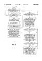
- FIG. 2is a high-level logical flowchart that illustrates the operation of the method and system of the present invention
- FIGS. 3 and 4further illustrate the operation of the method and system of the present invention in two different circumstances.
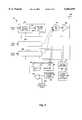
- FIG. 5is a transceiver according to the method and system of present invention.
- the processbegins at block 100 and thereafter passes to block 102 wherein the process determines for each subscriber unit a priority and a requested power.
- a subscriber unit's prioritymay be based upon one or more factors, such as whether or not the subscriber unit is set to receive real-time or non-real-time data, a level of service that the user has contracted for with the system operator, whether or not the subscriber unit is operating in an emergency situation, and other similar factors.
- a wireless communications systemmay be designed for two or more priority levels.
- a subscriber unit's requested powermay be determined by a direct request from the subscriber unit, or may be indirectly determined by examining metrics such as a frame erasure rate (FER).
- FERframe erasure rate
- the processdetermines whether or not the total requested power exceeds a maximum transceiver power, as illustrated at block 104.
- the total requested poweris the total of all power requested by each subscriber unit served by the transceiver.
- the maximum transceiver poweris the maximum power that the transceiver can safely transmit without damaging circuitry or causing other problems. If the total requested power does not exceed the maximum transceiver power, the process iteratively returns to block 102 to monitor for an overpower condition.
- the processdetermines an amount of power limiting that is needed to reduce the total transceiver transmit power below the maximum transceiver power, as depicted at block 106.
- the processgroups the subscriber units according to subscriber unit priority, as illustrated at block 108. Thereafter, the process sorts each priority group according to the amount of requested transmit power from each subscriber unit in the group, as depicted at block 110.
- the processcan select one or more subscriber units that will have their allocated power limited. As illustrated at block 112, the process first selects the subscriber in the lowest priority group who is requesting the largest amount of power. This subscriber is limited to the extent that the amount of power limiting needed is met, or until a minimum subscriber unit power is reached for that subscriber unit. If more than one subscriber unit must be limited to meet the amount of power limiting needed, the second largest power requesting subscriber unit in the group is limited until the total transceiver transmit power is below the maximum transceiver power, or until that subscriber unit is limited to a minimum subscriber unit power. This process of limiting continues in descending order of power requested until the amount of power limiting needed has been satisfied or until all the subscriber units in the lowest priority group have been limited to a minimum subscriber unit power.
- a minimum subscriber unit poweris preferably a power at which data is still being transferred at a minimum bit rate, which ensures that the call or data session continues without being dropped.
- a minimum bit ratemay be initiated as the result of reducing the power allocated to the subscriber unit. For example, as a subscriber unit's power begins to drop below a requested power, the subscriber unit may tolerate a higher error rate. As the error rate continues to increase, it may reach a point where the subscriber unit and the transceiver agree to communicate at a lower bit rate. This increases the reliability of the link because the bit time increases, thereby increasing the amount of energy per bit.
- the processdetermines whether or not the amount of power limiting needed has been met by limiting one or more subscriber units in the lowest priority group, as depicted at block 114. If the amount of power limiting has been met, the process returns to block 102 to determine whether or not additional power limiting is needed as a result of a subsequent power increase request. If the amount of power limiting needed is not met at block 114, the process begins limiting power to subscribers in the higher priority group in a manner similar to that discussed with respect to block 112.
- a minimum number of the largest power users in the higher priority groupare limited to a power not below a minimum subscriber unit power until a number of subscriber units has been limited to reduce a total transceiver transmit power below the maximum transceiver power.
- the processcontinues by sequentially placing subscriber units in the lowest priority group in a dormant state beginning with the subscriber requesting the largest amount of power until the amount of power limiting needed is met, as illustrated at blocks 118 and 120. If after placing the lowest priority subscribers in a dormant state the amount of power limiting is still not met, the process places the necessary number of high priority subscribers in a dormant state until the amount of power limiting needed is met, as depicted at blocks 122 and 124. Following block 124, the process returns to block 102.
- power allocated to subscriber unitsmay be increased so that eventually all subscriber units may be allocated an amount of power that they have requested.
- power limitingis eliminated because it is no longer needed.
- the process shown in the flowchart of FIG. 2is further illustrated.
- the processfirst determines for each subscriber unit an amount of requested power. This is shown graphically at reference numeral 200, wherein the amounts of power requested by subscriber units 54-62 (see FIG. 1) are shown with corresponding reference numerals 254-262.
- subscriber unit 54is requesting the least amount of power as shown at reference numeral 254 in FIG. 3, while subscriber unit 62 is requesting the largest amount of power, as indicated at reference numeral 262 in FIG. 3.
- a total power requestedmay be computed by summing all the requested power. This value is then compared to a maximum transceiver power 204, as shown graphically in FIG. 3. If this total requested amount of power exceeds the maximum transceiver power 204 the process sorts the subscriber units according to the amount of requested transmit power, as shown at reference numeral 206.
- allocated transmit power for a minimum number of selected subscriber unitsis limited by a level needed to reduce a total transceiver transmit power below the maximum transceiver power 204. This is illustrated at reference numeral 208, wherein the power requested by subscriber unit 62 has been limited to the allocated power shown at reference numeral 362.
- FIG. 4illustrates the situation in which two subscriber units are limited, as shown at reference numerals 362 and 360. Notice that in FIG. 4 maximum transceiver power 220 is so low that the amount of power limiting needed may not be met by limiting only the power to subscriber unit 62. In this example, the power allocated to subscriber unit 62 has been limited to a minimum subscriber unit power, which is enough power to keep the call to subscriber unit 62 active. The remaining amount of power limiting needed is taken from the power allocated to subscriber unit 60, as shown at reference numeral 360.
- the subscriber units requesting the largest amount of transceiver powerare limited first so as to limit a minimum number of subscriber units needed to reduce a total transceiver transmit power below the maximum transceiver power.
- the reason for thisis to adversely affect the fewest number of subscriber units while still limiting the amount of allocated power by the amount needed.
- Such adverse affects on the subscribersinclude delay in receiving data frames or degraded communications performance due to the lack of power requested.
- transceiver 46includes a plurality of channel processors 400 for receiving user data, and formatting and modulating such data for transmission to the subscriber units.
- channel processors 400are summed at summer 402. Following summer 402 the composite data, which includes data from all subscribers, is upconverted, modulated, and amplified in radio frequency transmitter 404. The output of radio frequency transmitter 404 is coupled to antenna 406.
- power control data receiver 408is used to receive data from subscriber units, wherein such data is used to allocate power in transceiver 46.
- datamay include a periodic stream of bits that direct transceiver 46 to increase or decrease power allocated to a particular subscriber unit by a preset amount.
- subscriber unitsmay request an absolute power setting, or may request an increase or decrease of a particular amount.
- the output of power control data receiver 408is coupled to power manager 410, which is used to keep track of and update the power requested by each subscriber unit.
- Outputs from power manager 410are coupled to channel power controls 412, which are located in each channel processor 400.
- channel power controls 412may be used to scale the user data in accordance with the power that has been allocated to the particular subscriber unit.
- Power manager 410is also coupled to requested power summer 414 and power limiter control 416. Data transferred to these two functions by power manager 410 includes data representing the requested power of each subscriber unit.
- the function of requested power summer 414is to add all requested power allocations and output a total requested power for all subscriber units served by transceiver 46. Such output is coupled to comparator 418 which computes the difference between the total requested power and maximum transceiver power 420.
- Maximum transceiver power 420may be a preset value, or may be computed based upon other critical values measured in transceiver 46. For example, maximum transceiver power 420 may be computed from temperatures measured in the amplifier in radio frequency transmitter 404.
- the output of comparator 418represents an amount of power that must be limited in order to protect components in radio frequency transmitter 404. This value is coupled to power limiter control 416, which is responsible for selecting subscriber units that will have their power limited in order to reduce the total transceiver transmit power below the maximum transceiver power.
- power limiter control 416includes sorter 422 and minimum allocated transmit power register 424.
- Sorter 422is used to sort the list of requested powers so that the subscriber units requesting the largest amounts of power may be quickly identified.
- Minimum allocated transmit power register 424may be used to store a variable representing a power level beyond which the subscriber unit will not be limited. This minimum allocated transmit power value is selected to maintain some data transfer between the transceiver and the subscriber unit, or, alternatively, to a level that avoids dropping the call. In some embodiments, however, the minimum allocated transmit power may be set to zero.
- Outputs of power limiter control 416are coupled to channel power limiters 426 in each channel processor 400.
- the purpose of channel power limiter 426is to reduce the power of the user data signal before the user data signal is sent to summer 402.
- the present inventionmay be used in a multi-carrier code division multiple access (CDMA) system.
- CDMAcode division multiple access
- the data transmitted to a subscriber unitis simultaneously transmitted on multiple carrier frequencies and the subscriber unit receives all of such frequencies in order to collect and demodulate the data. Therefore, in the multi-carrier system each of the transceivers used for the multiple carrier frequencies may be independently protected by the method and system of the invention. Thus, if some carrier frequencies include subscriber units that use only one carrier of the multiple carriers used by multi-carrier subscriber units, the limiting on that one carrier may be different than the limiting required on the other remaining carriers.
- the present inventionprotects sensitive circuitry in the transceiver while simultaneously increasing the capacity of the wireless communications system. This is effectively accomplished by substantially reducing the design margin used in the prior art to protect the transceiver and using the capacity contained in this design margin to serve additional users or to increase capacity.
Landscapes
- Engineering & Computer Science (AREA)
- Computer Networks & Wireless Communication (AREA)
- Signal Processing (AREA)
- Mobile Radio Communication Systems (AREA)
Abstract
Description
Claims (14)
Priority Applications (10)
| Application Number | Priority Date | Filing Date | Title |
|---|---|---|---|
| US09/113,391US6064659A (en) | 1998-07-10 | 1998-07-10 | Method and system for allocating transmit power to subscriber units in a wireless communications system |
| PCT/US1999/014004WO2000003487A1 (en) | 1998-07-10 | 1999-06-22 | Method and system for allocating transmit power to subscriber units in a wireless communications system |
| JP2000559645AJP4486752B2 (en) | 1998-07-10 | 1999-06-22 | Method and system for allocating transmit power to subscriber units in a wireless communication system |
| CA002336947ACA2336947C (en) | 1998-07-10 | 1999-06-22 | Method and system for allocating transmit power to subscriber units in a wireless communications system |
| KR10-2001-7000365AKR100405157B1 (en) | 1998-07-10 | 1999-06-22 | Method and system for allocating transmit power to subscriber units in a wireless communications system |
| EP99931851AEP1097518B1 (en) | 1998-07-10 | 1999-06-22 | Method and system for allocating transmit power to subscriber units in a wireless communications system |
| DE69940402TDE69940402D1 (en) | 1998-07-10 | 1999-06-22 | METHOD AND SYSTEM FOR ALLOCATING TRANSMISSION POWER TO DEVICES OF A WIRELESS MESSAGE SYSTEM |
| BRPI9911957-9ABR9911957B1 (en) | 1998-07-10 | 1999-06-22 | transceiver and method thereof for allocating transmission power to subscriber units in a wireless communications system. |
| IL14064499AIL140644A (en) | 1998-07-10 | 1999-06-22 | Method and system for allocating transmit power tosubscriber units in a wireless communications sys tem |
| CNB998096172ACN1153358C (en) | 1998-07-10 | 1999-06-22 | Method and system for allocating transmit power to subscriber units in a wireless communication system |
Applications Claiming Priority (1)
| Application Number | Priority Date | Filing Date | Title |
|---|---|---|---|
| US09/113,391US6064659A (en) | 1998-07-10 | 1998-07-10 | Method and system for allocating transmit power to subscriber units in a wireless communications system |
Publications (1)
| Publication Number | Publication Date |
|---|---|
| US6064659Atrue US6064659A (en) | 2000-05-16 |
Family
ID=22349128
Family Applications (1)
| Application Number | Title | Priority Date | Filing Date |
|---|---|---|---|
| US09/113,391Expired - LifetimeUS6064659A (en) | 1998-07-10 | 1998-07-10 | Method and system for allocating transmit power to subscriber units in a wireless communications system |
Country Status (10)
| Country | Link |
|---|---|
| US (1) | US6064659A (en) |
| EP (1) | EP1097518B1 (en) |
| JP (1) | JP4486752B2 (en) |
| KR (1) | KR100405157B1 (en) |
| CN (1) | CN1153358C (en) |
| BR (1) | BR9911957B1 (en) |
| CA (1) | CA2336947C (en) |
| DE (1) | DE69940402D1 (en) |
| IL (1) | IL140644A (en) |
| WO (1) | WO2000003487A1 (en) |
Cited By (22)
| Publication number | Priority date | Publication date | Assignee | Title |
|---|---|---|---|---|
| US20010027112A1 (en)* | 2000-02-29 | 2001-10-04 | Mitsubishi Denki Kabushiki Kaisha | System for controlling the transmission power of a base station with which a number of mobile stations are in communication |
| EP1160996A1 (en)* | 2001-02-02 | 2001-12-05 | Siemens Aktiengesellschaft | Method, apparatus and radio system for controlling the transmission characteristics of a first radio transmitter |
| US20020163923A1 (en)* | 2001-05-04 | 2002-11-07 | Cox Timothy F. | Power pooling in network downstream data transmission |
| US6580899B1 (en)* | 2000-09-07 | 2003-06-17 | Nortel Networks Limited | Adaptive forward power management algorithm for traffic hotspots |
| EP1331690A1 (en)* | 2002-01-23 | 2003-07-30 | Siemens Schweiz AG | Base station antenna arrangement with adjustable beam |
| EP1365520A1 (en)* | 2002-05-23 | 2003-11-26 | NTT DoCoMo, Inc. | Base station, and transmission power control method |
| US20040002341A1 (en)* | 2002-07-01 | 2004-01-01 | Tao Chen | Scheduling of data transmission for terminals with variable scheduling delays |
| EP1225710A3 (en)* | 2001-01-19 | 2004-01-28 | Motorola, Inc. | Method and apparatus for controlling channel gains and data rates to preserve voice quality in a CDMA system |
| US20040203986A1 (en)* | 2002-06-28 | 2004-10-14 | Marc Gagnon | Automatic transmit power control disabling |
| WO2004109951A1 (en)* | 2003-06-04 | 2004-12-16 | Siemens Aktiengesellschaft | Method for controlling transmitting power of at least two channels transmitting simultaneously from a transmitting station and transmitting station |
| WO2004112277A1 (en)* | 2003-06-13 | 2004-12-23 | Siemens Aktiengesellschaft | Power control for a mobile radio communication system |
| WO2005015768A1 (en)* | 2003-08-11 | 2005-02-17 | Koninklijke Philips Electronics N.V. | Power management in mobile terminals to allow transmission of ack/nack signals |
| US20050111391A1 (en)* | 2003-11-11 | 2005-05-26 | Sony Ericsson Mobile Communications Japan, Inc. | Mobile communication terminal and method of controlling transmission power |
| US20050282572A1 (en)* | 2002-11-08 | 2005-12-22 | Jeroen Wigard | Data transmission method, radio network controller and base station |
| US20060166690A1 (en)* | 2002-09-19 | 2006-07-27 | Matsushita Electric Industrial Co., Ltd. | Transmission power control method and base station device |
| US7167718B2 (en) | 2001-01-18 | 2007-01-23 | Ntt Docomo, Inc. | Transmission power control apparatus, transmission power control method, and mobile station |
| US7336629B1 (en)* | 1999-06-29 | 2008-02-26 | Nokia Corporation | Power control method and device |
| US20080306160A1 (en)* | 2005-08-29 | 2008-12-11 | Mamoru Kobayashi | Preventive or therapeutic agent for disease caused by decrease in lacrimal fluid |
| US7899484B2 (en) | 2003-12-17 | 2011-03-01 | Telefonaktiebolaget Lm Ericsson (Publ) | Power control method |
| EP1739858A4 (en)* | 2004-03-01 | 2014-12-24 | Nec Corp | WIRELESS BASE STATION UNIT AND TRANSMISSION CONTROL PROCEDURE |
| US20210127340A1 (en)* | 2015-05-01 | 2021-04-29 | Qualcomm Incorporated | Low latency uplink power control |
| US20250004535A1 (en)* | 2023-06-29 | 2025-01-02 | Red Hat, Inc. | Optimized power management for computer systems |
Families Citing this family (14)
| Publication number | Priority date | Publication date | Assignee | Title |
|---|---|---|---|---|
| EP1134911A1 (en) | 2000-03-17 | 2001-09-19 | Alcatel | Operating a cellular telecommunication system |
| CN1135745C (en)* | 2000-03-23 | 2004-01-21 | 华为技术有限公司 | CDMA Communication System Forward Power Saturation Protection Method and Power Control Device |
| US6862271B2 (en)* | 2002-02-26 | 2005-03-01 | Qualcomm Incorporated | Multiple-input, multiple-output (MIMO) systems with multiple transmission modes |
| US7660282B2 (en) | 2003-02-18 | 2010-02-09 | Qualcomm Incorporated | Congestion control in a wireless data network |
| EP1830480B1 (en)* | 2003-07-30 | 2009-04-15 | Interdigital Technology Corporation | Downlink power control with limit to dynamic range using detection of downlink transmit power |
| CN1833370B (en)* | 2003-07-30 | 2010-05-12 | 美商内数位科技公司 | Downlink power control with limit to dynamic range using detection of downlink transmit power |
| CN1868227B (en)* | 2003-10-17 | 2013-06-19 | 日本电气株式会社 | Signaling method, system, base station and mobile station |
| JP4837769B2 (en)* | 2003-11-11 | 2011-12-14 | ソニー・エリクソン・モバイルコミュニケーションズ株式会社 | Mobile communication terminal and transmission power control method |
| GB2411078B (en)* | 2004-02-10 | 2009-02-04 | Samsung Electronics Co Ltd | Mobile communications |
| US7698578B2 (en)* | 2006-06-29 | 2010-04-13 | Nokia Corporation | Temperature-dependent power adjustment of transmitter |
| EP2015492A1 (en)* | 2007-06-19 | 2009-01-14 | Nokia Siemens Networks Oy | Method for channel quality reporting, wireless communication device with channel quality reporting structures |
| CN101174860B (en)* | 2007-11-14 | 2011-05-11 | 中兴通讯股份有限公司 | Forward power overloads control method |
| DE102012219077A1 (en)* | 2012-10-08 | 2014-04-10 | Siemens Aktiengesellschaft | Method for distributing an electric power |
| EP3503635A1 (en)* | 2017-12-22 | 2019-06-26 | Fraunhofer-Gesellschaft zur Förderung der angewandten Forschung e.V. | Emergency notification (urllc) requesting spontaneous grant free transmission for v2x |
Citations (1)
| Publication number | Priority date | Publication date | Assignee | Title |
|---|---|---|---|---|
| US5794129A (en)* | 1995-07-14 | 1998-08-11 | Nec Corporation | Mobile communication system and base station for use therein |
Family Cites Families (8)
| Publication number | Priority date | Publication date | Assignee | Title |
|---|---|---|---|---|
| US5056109A (en)* | 1989-11-07 | 1991-10-08 | Qualcomm, Inc. | Method and apparatus for controlling transmission power in a cdma cellular mobile telephone system |
| US5345598A (en)* | 1992-04-10 | 1994-09-06 | Ericsson-Ge Mobile Communications Holding, Inc. | Duplex power control system in a communication network |
| KR100275118B1 (en)* | 1992-12-31 | 2000-12-15 | 김영환 | How to control recording speed |
| IT1261365B (en)* | 1993-12-02 | 1996-05-20 | Cselt Centro Studi Lab Telecom | PROCEDURE AND DEVICE FOR THE POWER CONTROL IN THE MOBILE BASE-HALF STATION ROUTE OF A RADIO-MOBILE SYSTEM WITH ACCESS TO CODE DIVISION |
| US5715526A (en)* | 1995-09-08 | 1998-02-03 | Qualcomm Incorporated | Apparatus and method for controlling transmission power in a cellular communications system |
| JP2959458B2 (en)* | 1996-01-19 | 1999-10-06 | 日本電気株式会社 | Transmission power control method |
| KR19990012755A (en)* | 1997-07-30 | 1999-02-25 | 윤종용 | Reverse power control device and method for reducing interference |
| JP3028802B2 (en)* | 1998-05-28 | 2000-04-04 | 日本電気株式会社 | Power control method during call capture in CDMA mobile communication system |
- 1998
- 1998-07-10USUS09/113,391patent/US6064659A/ennot_activeExpired - Lifetime
- 1999
- 1999-06-22JPJP2000559645Apatent/JP4486752B2/ennot_activeExpired - Fee Related
- 1999-06-22DEDE69940402Tpatent/DE69940402D1/ennot_activeExpired - Lifetime
- 1999-06-22CNCNB998096172Apatent/CN1153358C/ennot_activeExpired - Fee Related
- 1999-06-22ILIL14064499Apatent/IL140644A/ennot_activeIP Right Cessation
- 1999-06-22BRBRPI9911957-9Apatent/BR9911957B1/ennot_activeIP Right Cessation
- 1999-06-22EPEP99931851Apatent/EP1097518B1/ennot_activeExpired - Lifetime
- 1999-06-22CACA002336947Apatent/CA2336947C/ennot_activeExpired - Fee Related
- 1999-06-22WOPCT/US1999/014004patent/WO2000003487A1/ennot_activeApplication Discontinuation
- 1999-06-22KRKR10-2001-7000365Apatent/KR100405157B1/ennot_activeExpired - Fee Related
Patent Citations (1)
| Publication number | Priority date | Publication date | Assignee | Title |
|---|---|---|---|---|
| US5794129A (en)* | 1995-07-14 | 1998-08-11 | Nec Corporation | Mobile communication system and base station for use therein |
Cited By (42)
| Publication number | Priority date | Publication date | Assignee | Title |
|---|---|---|---|---|
| US7336629B1 (en)* | 1999-06-29 | 2008-02-26 | Nokia Corporation | Power control method and device |
| US20010027112A1 (en)* | 2000-02-29 | 2001-10-04 | Mitsubishi Denki Kabushiki Kaisha | System for controlling the transmission power of a base station with which a number of mobile stations are in communication |
| US6873856B2 (en)* | 2000-02-29 | 2005-03-29 | Mitsubishi Denki Kabushiki Kaisha | System for controlling the transmission power of a base station with which a number of mobile stations are in communication |
| US6580899B1 (en)* | 2000-09-07 | 2003-06-17 | Nortel Networks Limited | Adaptive forward power management algorithm for traffic hotspots |
| US7167718B2 (en) | 2001-01-18 | 2007-01-23 | Ntt Docomo, Inc. | Transmission power control apparatus, transmission power control method, and mobile station |
| EP1225710A3 (en)* | 2001-01-19 | 2004-01-28 | Motorola, Inc. | Method and apparatus for controlling channel gains and data rates to preserve voice quality in a CDMA system |
| US6775541B2 (en) | 2001-01-19 | 2004-08-10 | Motorola, Inc. | Method and apparatus for controlling data rates to preserve voice quality in a CDMA system |
| EP1160996A1 (en)* | 2001-02-02 | 2001-12-05 | Siemens Aktiengesellschaft | Method, apparatus and radio system for controlling the transmission characteristics of a first radio transmitter |
| US7016364B2 (en) | 2001-05-04 | 2006-03-21 | Alcatel Canada Inc. | Power pooling in network downstream data transmission |
| EP1255382A3 (en)* | 2001-05-04 | 2003-11-12 | Alcatel Canada Inc. | Method and apparatus of simultaneously transmitting data packets to multiple users using limited transmission power |
| US20020163923A1 (en)* | 2001-05-04 | 2002-11-07 | Cox Timothy F. | Power pooling in network downstream data transmission |
| EP1331690A1 (en)* | 2002-01-23 | 2003-07-30 | Siemens Schweiz AG | Base station antenna arrangement with adjustable beam |
| US20030171131A1 (en)* | 2002-01-23 | 2003-09-11 | Karl-Georg Kettering | Mobile radiotelephone antenna array with adjustable directional characteristic |
| US20030218993A1 (en)* | 2002-05-23 | 2003-11-27 | Ntt Docomo, Inc. | Base station, and transmission power control method |
| EP1365520A1 (en)* | 2002-05-23 | 2003-11-26 | NTT DoCoMo, Inc. | Base station, and transmission power control method |
| US20040203986A1 (en)* | 2002-06-28 | 2004-10-14 | Marc Gagnon | Automatic transmit power control disabling |
| US20070076723A1 (en)* | 2002-07-01 | 2007-04-05 | Qualcomm Incorporated | Scheduling of data transmission for terminals with variable scheduling delays |
| US7657264B2 (en) | 2002-07-01 | 2010-02-02 | Qualcomm Incorporated | Scheduling of data transmission for terminals with variable scheduling delays |
| US7164919B2 (en)* | 2002-07-01 | 2007-01-16 | Qualcomm Incorporated | Scheduling of data transmission for terminals with variable scheduling delays |
| US20040002341A1 (en)* | 2002-07-01 | 2004-01-01 | Tao Chen | Scheduling of data transmission for terminals with variable scheduling delays |
| US7561894B2 (en)* | 2002-09-19 | 2009-07-14 | Panasonic Corporation | Transmission power control method and base station device |
| US20060166690A1 (en)* | 2002-09-19 | 2006-07-27 | Matsushita Electric Industrial Co., Ltd. | Transmission power control method and base station device |
| US20050282572A1 (en)* | 2002-11-08 | 2005-12-22 | Jeroen Wigard | Data transmission method, radio network controller and base station |
| DE10325306A1 (en)* | 2003-06-04 | 2004-12-30 | Siemens Ag | Method for controlling transmission powers of at least two channels transmitted simultaneously by a transmitting station and transmitting station |
| WO2004109951A1 (en)* | 2003-06-04 | 2004-12-16 | Siemens Aktiengesellschaft | Method for controlling transmitting power of at least two channels transmitting simultaneously from a transmitting station and transmitting station |
| US7804814B2 (en) | 2003-06-13 | 2010-09-28 | Siemens Aktiengesellschaft | Power control for a mobile radio communication system |
| WO2004112277A1 (en)* | 2003-06-13 | 2004-12-23 | Siemens Aktiengesellschaft | Power control for a mobile radio communication system |
| US7831271B2 (en) | 2003-08-11 | 2010-11-09 | Koninklijke Philips Electronics N.V. | Communication system and method of operating the communicating system |
| US20080151840A1 (en)* | 2003-08-11 | 2008-06-26 | Koninklijke Philips Electronics N.V. | Communication System and Method of Operating the Communicating System |
| WO2005015768A1 (en)* | 2003-08-11 | 2005-02-17 | Koninklijke Philips Electronics N.V. | Power management in mobile terminals to allow transmission of ack/nack signals |
| US20050111391A1 (en)* | 2003-11-11 | 2005-05-26 | Sony Ericsson Mobile Communications Japan, Inc. | Mobile communication terminal and method of controlling transmission power |
| EP1531557A3 (en)* | 2003-11-11 | 2006-05-10 | Sony Ericsson Mobile Communications Japan, Inc. | Mobile communication terminal and method of controlling transmission power for a multiplex radio communication system |
| CN1619973B (en)* | 2003-11-11 | 2010-05-26 | 索尼爱立信移动通信日本株式会社 | Mobile communication terminal and method of controlling transmission power |
| US7403791B2 (en)* | 2003-11-11 | 2008-07-22 | Sony Ericsson Mobile Communications Japan, Inc. | Mobile communication terminal and method of controlling transmission power |
| US7899484B2 (en) | 2003-12-17 | 2011-03-01 | Telefonaktiebolaget Lm Ericsson (Publ) | Power control method |
| EP1698068B1 (en)* | 2003-12-17 | 2013-08-21 | TELEFONAKTIEBOLAGET LM ERICSSON (publ) | Power control method |
| EP1739858A4 (en)* | 2004-03-01 | 2014-12-24 | Nec Corp | WIRELESS BASE STATION UNIT AND TRANSMISSION CONTROL PROCEDURE |
| US20100197788A9 (en)* | 2005-08-29 | 2010-08-05 | Mamoru Kobayashi | Preventive or therapeutic agent for disease caused by decrease in lacrimal fluid |
| US20080306160A1 (en)* | 2005-08-29 | 2008-12-11 | Mamoru Kobayashi | Preventive or therapeutic agent for disease caused by decrease in lacrimal fluid |
| US20210127340A1 (en)* | 2015-05-01 | 2021-04-29 | Qualcomm Incorporated | Low latency uplink power control |
| US11722969B2 (en)* | 2015-05-01 | 2023-08-08 | Qualcomm Incorporated | Low latency uplink power control |
| US20250004535A1 (en)* | 2023-06-29 | 2025-01-02 | Red Hat, Inc. | Optimized power management for computer systems |
Also Published As
| Publication number | Publication date |
|---|---|
| BR9911957A (en) | 2001-03-27 |
| EP1097518A1 (en) | 2001-05-09 |
| JP2002520939A (en) | 2002-07-09 |
| BR9911957B1 (en) | 2012-06-12 |
| EP1097518B1 (en) | 2009-02-11 |
| WO2000003487A1 (en) | 2000-01-20 |
| CN1153358C (en) | 2004-06-09 |
| KR20010071811A (en) | 2001-07-31 |
| CA2336947A1 (en) | 2000-01-20 |
| IL140644A0 (en) | 2002-02-10 |
| DE69940402D1 (en) | 2009-03-26 |
| IL140644A (en) | 2005-12-18 |
| CA2336947C (en) | 2004-02-24 |
| CN1312975A (en) | 2001-09-12 |
| JP4486752B2 (en) | 2010-06-23 |
| KR100405157B1 (en) | 2003-11-12 |
| EP1097518A4 (en) | 2004-06-23 |
Similar Documents
| Publication | Publication Date | Title |
|---|---|---|
| US6064659A (en) | Method and system for allocating transmit power to subscriber units in a wireless communications system | |
| KR970003530B1 (en) | Transmission power control method in communication system | |
| US10531399B2 (en) | Radio resource management for a high-speed shared channel | |
| EP0720808B1 (en) | Method and apparatus for balancing the forward link handoff boundary to the reverse link handoff boundary in a cellular communication system | |
| EP0948869B1 (en) | Load monitoring and management in a cdma wireless communication system | |
| US6721568B1 (en) | Admission control in a mobile radio communications system | |
| US7016686B2 (en) | Congestion control in a CDMA-based mobile radio communications system | |
| JP3881027B2 (en) | Method and line device for selectively permitting communication in multi-user communication system | |
| US6233455B1 (en) | Method for utilizing negative T—COMP to improve handoff reliability | |
| EP1154667A2 (en) | Method and apparatus for multi-user resource management in wireless communication systems | |
| US20080261545A1 (en) | Communication terminal apparatus and base station apparatus | |
| US6775541B2 (en) | Method and apparatus for controlling data rates to preserve voice quality in a CDMA system | |
| CN100433596C (en) | Radio channel setting method, radio network controlling device and base station, and mobile communication system | |
| US20050025077A1 (en) | Reverse link rate control mechanism for QoS | |
| WO1997008909A1 (en) | A method of levelling a traffic load of a base station in a cellular radio system, and a cellular radio system | |
| JP3526243B2 (en) | Base station apparatus and line quality deterioration prevention method | |
| WO2001017311A1 (en) | Method and system for frequency spectrum resource allocation | |
| EP1282998A1 (en) | Improving the performance of a cdma system | |
| GB2347317A (en) | Determining a cost function from the actual resource impact of supporting a subscriber in a communications system | |
| US5802456A (en) | Method and apparatus to mitigate interference caused by an overlay communication system | |
| US20040085935A1 (en) | Performance of a CDMA system | |
| KR100330419B1 (en) | Admission Control Based on Cell Load in CDMA System | |
| JP2000050340A (en) | Method for controlling cell traffic load on base station in cdma cellular wireless communication system | |
| HK1023249B (en) | Load monitoring and management in a cdma wireless communication system | |
| HK1015218B (en) | Method and apparatus for balancing the forward link handoff boundary to the reverse link handoff boundary in a cellular communication system |
Legal Events
| Date | Code | Title | Description |
|---|---|---|---|
| AS | Assignment | Owner name:MOTOROLA, INC., ILLINOIS Free format text:ASSIGNMENT OF ASSIGNORS INTEREST;ASSIGNORS:ROHANI, KAMYAR;AHMED, MANSOOR;REEL/FRAME:009308/0158 Effective date:19980710 | |
| STCF | Information on status: patent grant | Free format text:PATENTED CASE | |
| FPAY | Fee payment | Year of fee payment:4 | |
| FPAY | Fee payment | Year of fee payment:8 | |
| AS | Assignment | Owner name:MOTOROLA MOBILITY, INC, ILLINOIS Free format text:ASSIGNMENT OF ASSIGNORS INTEREST;ASSIGNOR:MOTOROLA, INC;REEL/FRAME:025673/0558 Effective date:20100731 | |
| FPAY | Fee payment | Year of fee payment:12 | |
| AS | Assignment | Owner name:MOTOROLA MOBILITY LLC, ILLINOIS Free format text:CHANGE OF NAME;ASSIGNOR:MOTOROLA MOBILITY, INC.;REEL/FRAME:029216/0282 Effective date:20120622 | |
| AS | Assignment | Owner name:GOOGLE TECHNOLOGY HOLDINGS LLC, CALIFORNIA Free format text:ASSIGNMENT OF ASSIGNORS INTEREST;ASSIGNOR:MOTOROLA MOBILITY LLC;REEL/FRAME:034310/0001 Effective date:20141028 |