US6064372A - Touchscreen display system for a test instrument - Google Patents
Touchscreen display system for a test instrumentDownload PDFInfo
- Publication number
- US6064372A US6064372AUS08/758,036US75803696AUS6064372AUS 6064372 AUS6064372 AUS 6064372AUS 75803696 AUS75803696 AUS 75803696AUS 6064372 AUS6064372 AUS 6064372A
- Authority
- US
- United States
- Prior art keywords
- test instrument
- user interface
- softkey
- graphical user
- indicators
- Prior art date
- Legal status (The legal status is an assumption and is not a legal conclusion. Google has not performed a legal analysis and makes no representation as to the accuracy of the status listed.)
- Expired - Lifetime
Links
Images


Classifications
- G—PHYSICS
- G06—COMPUTING OR CALCULATING; COUNTING
- G06F—ELECTRIC DIGITAL DATA PROCESSING
- G06F3/00—Input arrangements for transferring data to be processed into a form capable of being handled by the computer; Output arrangements for transferring data from processing unit to output unit, e.g. interface arrangements
- G06F3/01—Input arrangements or combined input and output arrangements for interaction between user and computer
- G06F3/048—Interaction techniques based on graphical user interfaces [GUI]
- G06F3/0487—Interaction techniques based on graphical user interfaces [GUI] using specific features provided by the input device, e.g. functions controlled by the rotation of a mouse with dual sensing arrangements, or of the nature of the input device, e.g. tap gestures based on pressure sensed by a digitiser
- G06F3/0489—Interaction techniques based on graphical user interfaces [GUI] using specific features provided by the input device, e.g. functions controlled by the rotation of a mouse with dual sensing arrangements, or of the nature of the input device, e.g. tap gestures based on pressure sensed by a digitiser using dedicated keyboard keys or combinations thereof
- G—PHYSICS
- G06—COMPUTING OR CALCULATING; COUNTING
- G06F—ELECTRIC DIGITAL DATA PROCESSING
- G06F1/00—Details not covered by groups G06F3/00 - G06F13/00 and G06F21/00
- G06F1/16—Constructional details or arrangements
- G06F1/1601—Constructional details related to the housing of computer displays, e.g. of CRT monitors, of flat displays
- G—PHYSICS
- G06—COMPUTING OR CALCULATING; COUNTING
- G06F—ELECTRIC DIGITAL DATA PROCESSING
- G06F3/00—Input arrangements for transferring data to be processed into a form capable of being handled by the computer; Output arrangements for transferring data from processing unit to output unit, e.g. interface arrangements
- G06F3/01—Input arrangements or combined input and output arrangements for interaction between user and computer
- G06F3/048—Interaction techniques based on graphical user interfaces [GUI]
- G06F3/0487—Interaction techniques based on graphical user interfaces [GUI] using specific features provided by the input device, e.g. functions controlled by the rotation of a mouse with dual sensing arrangements, or of the nature of the input device, e.g. tap gestures based on pressure sensed by a digitiser
- G06F3/0488—Interaction techniques based on graphical user interfaces [GUI] using specific features provided by the input device, e.g. functions controlled by the rotation of a mouse with dual sensing arrangements, or of the nature of the input device, e.g. tap gestures based on pressure sensed by a digitiser using a touch-screen or digitiser, e.g. input of commands through traced gestures
- G06F3/04886—Interaction techniques based on graphical user interfaces [GUI] using specific features provided by the input device, e.g. functions controlled by the rotation of a mouse with dual sensing arrangements, or of the nature of the input device, e.g. tap gestures based on pressure sensed by a digitiser using a touch-screen or digitiser, e.g. input of commands through traced gestures by partitioning the display area of the touch-screen or the surface of the digitising tablet into independently controllable areas, e.g. virtual keyboards or menus
- G—PHYSICS
- G06—COMPUTING OR CALCULATING; COUNTING
- G06F—ELECTRIC DIGITAL DATA PROCESSING
- G06F2200/00—Indexing scheme relating to G06F1/04 - G06F1/32
- G06F2200/16—Indexing scheme relating to G06F1/16 - G06F1/18
- G06F2200/161—Indexing scheme relating to constructional details of the monitor
- G06F2200/1612—Flat panel monitor
Definitions
- This inventionrelates generally to graphical user interfaces and in particular to a touchscreen display system used in conjunction with associated indicators for controlling a handheld, electronic test instrument.
- Touchscreen technologyhas provided a more recent innovation in user interface technology by allowing the user to touch a designated area of the graphical interface to generate an output signal rather than pressing a softkey adjacent to the graphical interface.
- Graphical displays employing colorsare now available to further enhance instrument usability.
- Touchscreen display technologyhas largely been driven by the market demands of the computer industry for the personal digital assistant (PDA) which is designed as a portable, hand-held computer.
- PDApersonal digital assistant
- the touchscreen user interfacecan be implemented in a smaller physical space, with enhanced versatility and reduced cost.
- Handheld, portable test instrumentshave been developed that successfully employ graphical user interfaces in combination with softkeys, including portable digital storage oscilloscopes (DSOs) and local area network (LAN) test instruments.
- DSOsportable digital storage oscilloscopes
- LANlocal area network
- LCD display technologywhile extensively used in touchscreen user interfaces, often requires power consuming backlight circuits in order generate light in order to be seen in low ambient light conditions. The information on LCD displays is visible only from limited viewing angles which makes the operation of the portable test instrument more difficult.
- Indicator lights or indicatorshave been added to the front panels of some test instruments to augment graphical displays as the user interface.
- Indicatorsprovide for the visual indication of basic information about selected parameters.
- a selected parametermay include the status of a link pulse in the case of a LAN.
- Basic information about selected parametersmay include the presence or absence of a link pulse on a LAN being tested, the presence or absence of an error condition, or the detection of a collision.
- Indicatorsare often implemented using light emitting diodes (LEDs) which require relatively little power, are easy to see even in low ambient light, and allow for fast cognition of the basic information by the user of the test instrument.
- LEDslight emitting diodes
- Indicators in prior art instrumentsare typically located on the front panel adjacent to a permanent label and with no visual linkage to softkeys, thus limiting their ability to be used in multiple roles. Such indicators have not been visually associated with the operation of the graphical display and softkeys in prior art instrument designs. Without this visual association, an error indicator will show that further investigation is needed using detailed information but provides no visual prompt as to how to proceed in order to obtain the detailed information appropriate for that error indicator. Because the visual association between the indicator and user action is not readily apparent, the user is likely to be confused as to what action is required.
- a graphical user interface for a test instrumentemploying a set of softkeys with a set of indicators that are directly linked to the softkeys to provide a visual prompt for further actions. It would be further desirable that the indicators display basic information about selected parameters in parallel fashion using a selected set of colors for fast visual interpretation by the user.
- a graphical user interface with associated indicators for a test instrumentis provided.
- the graphical user interfaceis implemented with touchscreen technology in which the functions of graphical display and user entry are combined.
- a set of indicatorsis mounted around the periphery of the touchscreen display so that each indicator is associated with a softkey on the touchscreen.
- Each of the indicatorsis chosen to indicate basic information about a selected parameter that is necessary to communicate with the user of the test instrument in an unambiguous manner.
- An example of a selected parameteris the status of a link pulse in a LAN connected to the test instrument.
- Basic information about the link pulsecould include the presence or absence of the link pulse and whether there is a problem detected on the link pulse that is present.
- the present inventionis applied in a LAN test instrument which is coupled to a LAN to receive and analyze data traffic which appear as discrete frames. Each frame is received and processed to obtain network information.
- the network informationincludes a number of parameters such as the network utilization and the number of collisions on the LAN that may be displayed graphically as detailed information on the touchscreen display.
- the selected parametersare displayed as basic information using a set of indicators that operate in parallel for each of the selected parameters and that are associated with softkeys drawn on the touchscreen display.
- the set of indicatorsshow simultaneous basic information about a set of selected parameters which may be viewed in combination by the user.
- a selected parameter such as network utilizationmay be displayed on the indicator using the set of selected colors.
- the set of selected colorspreferably consist of high-contrast primary colors that are easily distinguished from each other. For example, green may be chosen to show low utilization, yellow to show medium utilization, and red to show high utilization.
- the use of actively-generated light in a selected color by the indicatorprovides for an easily interpreted indication of the selected parameter that may be viewed in any lighting condition, over a wide viewing angle, and without having to view and interpret the touchscreen display.
- each indicatoris coupled to softkeys drawn on the touchscreen display, an action of the test instrument is directly linked to a visual prompt created according to the selected color of an indicator.
- Each indicatormay be thus used to visually prompt an action using the associated softkey.
- a utilization indicatorthat is indicating the color red corresponding to a high utilization rate of the LAN is an unusual condition that will likely prompt the user to seek further detailed information from the test instrument.
- the softkey associated with the utilization indicator labeled "UTIL"may then be pressed and detailed information about the selected parameter of utilization may then be obtained from the touchscreen display.
- a set of selected parametersincludes the presence of the link pulse, the relative utilization rate, the occurrence of collisions, and the occurrence of errors.
- Each of the selected parametershas an associated indicator and softkey having an appropriate label.
- Each indicatorindicates basic information about a selected parameter and the softkey may be pressed to obtain detailed information responsive to the selected color of the indicator.
- the test instrumentBy providing the set of indicators for basic information of network parameters that operate independently and in parallel with each other, the test instrument provides a quick, unambiguous visual indication of the status of the LAN being measured in the form of basic information that can be interpreted visually in combination by the user. Detailed information may be readily obtained by pressing the labeled softkeys associated with each indicator which provides visual prompts. As the instrument status changes or the network information changes, the softkey labels may be readily changed, thereby changing the meaning of the associated indicators and the action of the softkeys. Furthermore, each of the softkey labels may be localized to the language of the test instrument user.
- One object of the present inventionis to provide a graphical user interface for a test instrument using softkeys and associated indicator for a test instrument.
- Another object of the present inventionis to provide a touchscreen user interface having softkeys with associated indicators for a test instrument.
- An additional object of the present inventionis to provide a touchscreen user interface associated with indicators for a test instrument to visually indicate basic information about selected parameters using a selected set of colors.
- a further object of the present inventionis to provide a touchscreen user interface for a LAN test instrument with indicators associated with softkeys to visually prompt an action by the user to obtain detailed information by pressing an appropriate softkey.
- FIG. 1is a simplified view (not to scale) of a test instrument with a touchscreen interface and associated indicators according to the present invention as applied to testing a local area network;
- FIG. 2is a top view of the test instrument of FIG. 1 showing the touchscreen interface for displaying detailed information and associated indicators for displaying basic information;
- FIG. 3is a simplified block diagram of the test instrument of FIG. 1 showing the operation of the touchscreen interface and associated indicators;
- FIG. 4is a simplified block diagram of an alternative embodiment of the test instrument of FIG. 1 showing the operation of a graphical user interface, separate softkeys, and associated indicators;
- FIG. 5is a table mapping the indicator color to basic information as a function of the selected parameters
- FIG. 6is an example of indicator status which visually prompts an action by a user of the test instrument to press a labeled softkey
- FIG. 7is another example of indicator status which visually prompts an action by a user of the test instrument to press a labeled softkey
- FIG. 8is a further example of indicator status which visually prompts an action by a user of the test instrument to press a labeled softkey
- FIG. 9is an example of detailed information about selected parameters that may be viewed on the touchscreen display of the test instrument after pressing a labeled softkey.
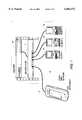
- FIG. 1is an illustration (not to scale) of a test instrument 10 with a touchscreen user interface and associated indicators according to the present invention as applied to testing a local area network (LAN) 12.
- the test instrument 10is designed to be handheld, portable, and battery-operated, requiring that the user interface be compact, draw relatively little power and be capable of displaying relatively complex information, particularly in situations such as shown in FIG. 1.
- highly complex network informationis acquired and displayed, both as basic information and as detailed information by the test instrument 10 which must then be interpreted by the user.
- the LAN 12is typical of what may be encountered in service, installation, and maintenance applications.
- a shared hub 14is coupled to devices 16, 18, and 20, labeled CLIENT 1, 2, and 3 respectively, as well as a router 22 to form a typical local area network (LAN).
- the LAN 12is typically implemented using the Ethernet protocol which provides for a base-band network in which the devices communicate with each other using data formatted as frames or packets.
- the test instrument 10must be capable of displaying the network information in a manner that may be quickly understood by the user, often in cramped physical environments such as telecommunications closets where ambient light is poor.
- Network information from the LAN 12 gathered by the test instrument 10may include the presence of the link pulse from the shared hub 14, the level of utilization of the LAN 12, the presence of collisions in the traffic between the devices 16, 18, and 20, and the presence of errors on the LAN 12. While displaying network information as detailed information on the touchscreen display is necessary and desirable, combining a set of indicators that are associated with labeled softkeys on the touchscreen display greatly enhances the usability of the test instrument 10 by providing a quick, unambiguous visual display of the all the selected parameters in combination as basic information using emitted light according to a set of selected colors. In this way, the test instrument 10 provides a "go-no go" type of test result which may be all that is needed for a particular situation. At the same time, the set of indicators provides links to obtain detailed information about a selected parameter by providing a visual prompt to press the associated softkey.
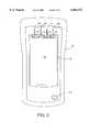
- FIG. 2is a top view of the test instrument 10 showing a touchscreen interface 50 mounted on an upper surface of the test instrument 10 for displaying detailed information.
- a row of softkeys 70, 72, 74, and 76are drawn near the top edge of the touchscreen interface 50.
- Indicators 60, 62, 64 and 66are mounted on the upper surface adjacent to the top edge of the touchscreen interface 50 and are positioned to physically correspond respectively with the softkeys 70, 72, 74, and 76.
- An area 52 of the touchscreen interface 50is used for displaying detailed information graphically or numerically, typically in response to a press of one of the softkeys 70, 72, 74, and 76.
- An on-off switch 40is mounted on the upper surface for turning the test instrument 10 on and off.
- the indicators 60, 62, 64, and 66may be arranged around the periphery of the touchscreen interface 50 and in greater or fewer numbers of indicators as needed. Each indicator is visually associated with a softkey on the touchscreen interface 50 typically by physical proximity. Softkeys 70, 72, 74, and 76 are shown drawn as rectangles on the touchscreen interface 50. The softkeys 70, 72, 74, and 76 contain the labels "Link”, “Util”, “Colsn”, and "Error” respectively, with each label corresponding to a selected parameter of the network information gathered from the LAN 12 being tested by the test instrument 10.
- the softkeys 70, 72, 74, and 76are associated with the indicators 60, 62, 64, and 66 respectively, by physical proximity and each association is enhanced by physical lines drawn on or etched into the top surface of the test instrument 10 between each of the softkeys 70, 72, 74, and 76 and the indicators 60, 62, 64, and 66 respectively.
- the indicators 60, 62, 64, and 66are preferably implemented using commercially available light emitting diodes (LEDs) which draw relatively little current while having the ability to generate light in accordance with to a selected set of colors.
- LEDsthat selectively produce red, yellow, and green colors from the same LED component are used for enhanced versatility.
- Multiple LED components for one indicatormay be readily combined to form one indicator.
- Other indicator colorsmay be readily substituted based on available technology and the requirements for the test instrument 10.
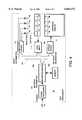
- FIG. 3is a simplified block diagram of the test instrument 10 showing the operation of the touchscreen interface 50 and the indicators 60 - 66.
- the test instrument 10is coupled to the LAN 12 to receive network traffic in the form of frames.
- the framesare received by a frame processor 100 which generates network information in terms of selected parameters including collisions, presence of errors and the link pulse, amount of utilization, along with other network information such as the types of devices on the LAN 12 based on the frames received.
- the frame processor 100may be implemented in hardware, software, or a combination thereof within the test instrument 10.
- the network information generated by the frame processing operation 100is received by a microprocessor 102 which executes an instrument control program contained in a memory 104.
- the network informationis typically stored as a database in the memory 104 and then further analyzed by the microprocessor 102.
- the network information gatheredmay be displayed to the user as selected parameters in terms of basic information and also in terms of detailed information.
- the network informationis communicated to the user of the test instrument 10 via the touchscreen interface 50 usually as detailed information that is shown in graphical or alphanumeric format in the area 52 (shown in FIG. 2) or as basic information that is shown on the indicators 60-66.
- the microprocessor 102places the detailed information on the touchscreen interface 50 via a data bus 106 to a screen driver 108 which handles the details of interface formatting and control.
- Each locationmust be matched to one of the softkeys 70, 72, 74 and 76 which are drawn as rectangles in order to constitute a valid key press for that softkey.
- Each of the softkeys 70, 72, 74 and 76has a label which defines its meaning and the meaning of the associated indicator in terms of the selected parameters. Each label may be readily redefined as desired according to the needs of the overall user interface design, either as new instrument configurations or to localize the user interface to relevant languages for world-wide markets.
- the microprocessor 102displays the basic information on the indicators 60-66 via an indicator driver 112.
- the indicator driver 112may be implemented in hardware, software, or a combination thereof in order to provide electrical signals to activate each of the indicators 60-66 with the desired colors.
- the indicators 60-66are preferably updated at a rate that is high enough so that the status of each indicator appears to resemble a "real time" viewing of the selected parameters as they occur on the LAN 12.
- the indicator driver 112allows the indicators 60-66 to operate essentially in parallel and independently of one another so that multiple selected parameters may be visually interpreted in combination by the user.
- FIG. 4shows an alternative embodiment of the present invention in which the touchscreen interface 50 is replaced by a graphical display 51.
- the softkeys 70, 72, 74, and 76 that were drawn on the touchscreen interface 50are replaced with softkeys 70', 72', 74', and 76' that are physical switches constructed in the conventional manner.
- the indicators 60, 62, 64, and 66are associated with the softkeys 70', 72', 74', and 76'.
- a set of softkey labels 90, 92, 94, and 96 drawn on the graphical display 51are associated with the softkeys 70', 72', 74', and 76'.
- the user input 110accepts the keypresses by each of the softkeys 70', 72', 74', and 76' and passes the keypresses on to the microprocessor 102.
- FIG. 5there is shown a table 200 mapping the set of selected colors for the indicators to the basic information as a function of the selected parameter.
- Each indicatormay be off or on by displaying one of a selected set of colors.
- the colorsinclude green, yellow, or red which are chosen based on the application requirements and the available technology.
- a set of four indicator states 80, 82, 84 and 86are shown which are mapped to the indicator colors red, yellow, green, and off respectively. Off is typically a dark indicator rather than a positive emission of visible light.
- the basic information about the selected parameters communicated by the indicators 60, 62, 64, and 66includes link pulse, utilization, collision, and error which are placed as labels in abbreviated form in the softkeys 70, 72, 74, and 76.
- the indicator 60 associated with the softkey 70has three indicator states defined according to the selected set of colors, including off for no link pulse, green for link pulse detected, and yellow for problems detected on the link pulse.
- the color yellowwould provide a visual prompt the user to press the softkey 70 to obtain detailed information on the nature of the problem detected on the link pulse.
- the indicator 62 associated with the softkey 72has four indicator states defined, including off for no utilization, red for high utilization, yellow for medium utilization, and green for low utilization.
- the definition of what constitutes low, medium, and high levels of utilizationmay be determined by a reasonable amount of experimentation or set according to commonly understood standards in the industry.
- the colors red and yellowtend to indicate a higher severity level which would visually prompt the user to press the softkey 72 to obtain detailed information on the nature of the utilization to determine if there is a problem. Because the level of utilization on a typical LAN varies in an unpredictable manner from one moment to the next, it is desirable that the state of the indicator 62 be updated rapidly to allow for better evaluation by the user of the test instrument 10.
- the indicator 64 associated with the softkey 74has two indicator states defined, including off for no collisions detected and yellow for collisions detected.
- the color yellowwould provide a visual prompt to the user to press the softkey 74 to obtain detailed information on the level of collisions to determine if there is a problem. Because collisions are transitory events which the Ethernet protocol, among others, is designed to handle, it is desirable that the state of the indicator 64 be updated rapidly to allow for better evaluation by the user by observing the level of collisions occurring moment by moment.
- the indicator 66 associated with the softkey 76has two states defined, including off for no errors detected and red for errors detected.
- the color redwould visually prompt the user to press the softkey 76 to obtained detailed information on the level of collisions to determine if there is a problem.
- the presence of errors on the networkare typically transitory events such as short frames, "jabbers", and bad frame check sequences, all of which are corrected for under the network protocols by automatically re-sending the information. It is desirable that the state of the indicator 66 be updated rapidly to allow for better evaluation by the user by observing the level of errors occurring moment by moment.
- FIG. 6, FIG. 7, and FIG. 8are examples of typical scenarios that may be encountered by the user in applying the test instrument 10 which has a touchscreen interface 50 with the indicators 60-66 according to the present invention.
- the indicators 60-66operate independently in displaying the basic information according to a selected set of parameters.
- the display of all the indicator states from the indicators 60-66 operating to view all the basic information in combinationis desirable because the user can view an overall "picture" of the selected parameters. Examples of typical situations that benefit from the parallel display of selected parameters is explained in further detail below.
- FIG. 6there are shown the indicators 60-66 as associated with the softkeys 70-76 drawn on the touchscreen interface 50.
- the indicator 60is shown having the color green according to the table 200 which is associated with the softkey 70 labeled "Link”.
- the indicator 62is shown having the color yellow according to the table 200 which is associated with the softkey 72 labeled "Util”.
- the indicators 64 and 66are off. This situation may occur when the test instrument 10 is coupled to the LAN 12 with a proper link pulse and a moderate amount of traffic. The absence of errors and collisions is indicated by the indicators 64 and 66 being off.
- the choice of colors from the set of selected colors of the indicators to indicate these conditionsis arbitrary.
- the colors green, yellow, and redwere chosen in the preferred embodiment to aid rapid cognition by the user because of their analogy to the meaning of the colors in traffic signals where red means stop, yellow means caution, and green means go.
- the indicator 62 having a color of yellow or red associated with moderate or high levels of utilizationwill provide a visual prompt to the user to press the softkey "Util" to obtain more detailed information about the utilization on the network.
- the detailed informationcould include a listing of the devices that are the sending most of the traffic as well as a more precise figure of utilization such as "40%".
- FIG. 7there are shown the indicators 60-66 as associated with the softkeys 70-76 drawn on the touchscreen interface 50 similar to FIG. 5.
- the indicator 60is shown having the color green according to the table 200 which is associated with the softkey 70 labeled "Link”.
- the indicator 62is also shown having the color green according to the table 200 which is associated with the softkey 72 labeled "Util”.
- the indicator 64is shown having the color yellow according to the table 200 which is associated with the softkey 72 labeled "Colsn”.
- the indicator 66is off. This situation may occur when the test instrument 10 is coupled to the LAN 12 with a proper link pulse and a low amount of traffic but with collisions being detected.
- the indicator 64 emitting yellow lightwill visually prompt the user to press the softkey "Colsn" to obtain more detailed information about the collisions occurring on the LAN to determine if there actually is a problem.
- FIG. 8there is shown the set of indicators 60-66 as associated with the softkeys 70-76 which are drawn on the touchscreen interface 50 similar to FIG. 5.
- the indicator 60is shown having the color green according to the table 200 which is associated with the softkey 70 labeled "Link”.
- the indicator 62is also shown having the color green according to the table 200 which is associated with the softkey 72 labeled "Util”.
- the indicator 64is off.
- the indicator 66is shown having the color red according to the table 200 which is associated with the softkey 76 labeled "Error”. This situation may occur when the test instrument 10 is coupled to the LAN 12 with a proper link pulse and a low amount of traffic but with an error condition on the LAN 12. Detected errors are definite problems requiring further analysis by the user.
- the indicator 66 emitting red lightwill visually prompt the user to press the softkey "Error" to obtain more detailed information about the nature of the error.
- FIG. 9is an example of a bit-mapped display image that could appear in the area 52 (shown in FIG. 2) that shows detailed information about a selected parameter. This detailed information could be accessed by pressing one of the softkeys 70, 72, 74, or 76 in response to a visual prompt provided by one of the indicators 60, 62, 64, or 66 that display the basic information about the selected parameters.
- the indicatorscan be implemented in any type of lighting technology that allows for at least one color of light to be emitted and provides the user with basic information that is easily interpreted and is visually associated with the appropriate softkey on the touchscreen display.
- indicatorsmay be chosen that have selectable flashing rates or selectable light intensities.
- the present inventionmay readily be adapted for conventional graphical displays which operate in conjunction with softkeys as long as the indicators are linked to the softkey so as to visually associate an action by the user.
- the present inventionmay be readily adapted to different types of test instruments that allow for basic information and detailed information to be displayed. Therefore, the scope of the present invention should be determined by the following claims.
Landscapes
- Engineering & Computer Science (AREA)
- General Engineering & Computer Science (AREA)
- Theoretical Computer Science (AREA)
- Human Computer Interaction (AREA)
- Physics & Mathematics (AREA)
- General Physics & Mathematics (AREA)
- Computer Hardware Design (AREA)
- User Interface Of Digital Computer (AREA)
Abstract
Description
This invention relates generally to graphical user interfaces and in particular to a touchscreen display system used in conjunction with associated indicators for controlling a handheld, electronic test instrument.
Electronic test instruments such as oscilloscopes have traditionally used graphical display in conjunction with softkeys to obtain an improved user interface. In the typical user interface, softkeys are placed around the periphery of the graphical display, either in the form of a cathode ray tube (CRT) or, more recently, liquid crystal displays (LCDs). Softkey labels are drawn on the graphical display adjacent to the softkey, so that the function and action associated with the softkey may be readily defined and re-defined according to the particular state of the user interface.
Touchscreen technology has provided a more recent innovation in user interface technology by allowing the user to touch a designated area of the graphical interface to generate an output signal rather than pressing a softkey adjacent to the graphical interface. Graphical displays employing colors are now available to further enhance instrument usability. Touchscreen display technology has largely been driven by the market demands of the computer industry for the personal digital assistant (PDA) which is designed as a portable, hand-held computer. By combining the functions of user input and graphical display output, the touchscreen user interface can be implemented in a smaller physical space, with enhanced versatility and reduced cost.
Handheld, portable test instruments have been developed that successfully employ graphical user interfaces in combination with softkeys, including portable digital storage oscilloscopes (DSOs) and local area network (LAN) test instruments. Most portable test instruments have substantial constraints on size and battery power which dictates the use of LCD technology for graphical user interfaces.
Portable test instruments with LCD graphical displays are increasingly being used in service, installation, and maintenance applications which often involve cramped locations and poor lighting conditions, by technicians who may only need to see certain basic information about what is being measured. LCD display technology, while extensively used in touchscreen user interfaces, often requires power consuming backlight circuits in order generate light in order to be seen in low ambient light conditions. The information on LCD displays is visible only from limited viewing angles which makes the operation of the portable test instrument more difficult.
Indicator lights or indicators have been added to the front panels of some test instruments to augment graphical displays as the user interface. Indicators provide for the visual indication of basic information about selected parameters. A selected parameter may include the status of a link pulse in the case of a LAN. Basic information about selected parameters may include the presence or absence of a link pulse on a LAN being tested, the presence or absence of an error condition, or the detection of a collision. Indicators are often implemented using light emitting diodes (LEDs) which require relatively little power, are easy to see even in low ambient light, and allow for fast cognition of the basic information by the user of the test instrument.
Indicators in prior art instruments are typically located on the front panel adjacent to a permanent label and with no visual linkage to softkeys, thus limiting their ability to be used in multiple roles. Such indicators have not been visually associated with the operation of the graphical display and softkeys in prior art instrument designs. Without this visual association, an error indicator will show that further investigation is needed using detailed information but provides no visual prompt as to how to proceed in order to obtain the detailed information appropriate for that error indicator. Because the visual association between the indicator and user action is not readily apparent, the user is likely to be confused as to what action is required.
Therefore, it would be desirable to provide a graphical user interface for a test instrument employing a set of softkeys with a set of indicators that are directly linked to the softkeys to provide a visual prompt for further actions. It would be further desirable that the indicators display basic information about selected parameters in parallel fashion using a selected set of colors for fast visual interpretation by the user.
In accordance with the present invention, a graphical user interface with associated indicators for a test instrument is provided. The graphical user interface is implemented with touchscreen technology in which the functions of graphical display and user entry are combined. A set of indicators is mounted around the periphery of the touchscreen display so that each indicator is associated with a softkey on the touchscreen.
Each of the indicators is chosen to indicate basic information about a selected parameter that is necessary to communicate with the user of the test instrument in an unambiguous manner. An example of a selected parameter is the status of a link pulse in a LAN connected to the test instrument. Basic information about the link pulse could include the presence or absence of the link pulse and whether there is a problem detected on the link pulse that is present.
The present invention is applied in a LAN test instrument which is coupled to a LAN to receive and analyze data traffic which appear as discrete frames. Each frame is received and processed to obtain network information. The network information includes a number of parameters such as the network utilization and the number of collisions on the LAN that may be displayed graphically as detailed information on the touchscreen display.
It is known that the display of information using generated light according to a selected set of colors provides for much faster cognition and interpretation by a user than a display of the same information in graphical or numerical form. Indicators are used to take advantage of this fact by allowing for visual association of basic information with the colors and with softkeys, rapid interpretation of the basic information even as the indicator colors rapidly change, and the interpretation of a group of indicators in combination to quickly arrive at overall interpretations of the network information without navigating a menu.
The selected parameters are displayed as basic information using a set of indicators that operate in parallel for each of the selected parameters and that are associated with softkeys drawn on the touchscreen display. The set of indicators show simultaneous basic information about a set of selected parameters which may be viewed in combination by the user.
A selected parameter such as network utilization may be displayed on the indicator using the set of selected colors. The set of selected colors preferably consist of high-contrast primary colors that are easily distinguished from each other. For example, green may be chosen to show low utilization, yellow to show medium utilization, and red to show high utilization. The use of actively-generated light in a selected color by the indicator provides for an easily interpreted indication of the selected parameter that may be viewed in any lighting condition, over a wide viewing angle, and without having to view and interpret the touchscreen display.
Because each indicator is coupled to softkeys drawn on the touchscreen display, an action of the test instrument is directly linked to a visual prompt created according to the selected color of an indicator. Each indicator may be thus used to visually prompt an action using the associated softkey. For example, a utilization indicator that is indicating the color red corresponding to a high utilization rate of the LAN is an unusual condition that will likely prompt the user to seek further detailed information from the test instrument. The softkey associated with the utilization indicator labeled "UTIL" may then be pressed and detailed information about the selected parameter of utilization may then be obtained from the touchscreen display.
As applied in a test instrument for LANs, a set of selected parameters includes the presence of the link pulse, the relative utilization rate, the occurrence of collisions, and the occurrence of errors. Each of the selected parameters has an associated indicator and softkey having an appropriate label. Each indicator indicates basic information about a selected parameter and the softkey may be pressed to obtain detailed information responsive to the selected color of the indicator.
By providing the set of indicators for basic information of network parameters that operate independently and in parallel with each other, the test instrument provides a quick, unambiguous visual indication of the status of the LAN being measured in the form of basic information that can be interpreted visually in combination by the user. Detailed information may be readily obtained by pressing the labeled softkeys associated with each indicator which provides visual prompts. As the instrument status changes or the network information changes, the softkey labels may be readily changed, thereby changing the meaning of the associated indicators and the action of the softkeys. Furthermore, each of the softkey labels may be localized to the language of the test instrument user.
One object of the present invention is to provide a graphical user interface for a test instrument using softkeys and associated indicator for a test instrument.
Another object of the present invention is to provide a touchscreen user interface having softkeys with associated indicators for a test instrument.
An additional object of the present invention is to provide a touchscreen user interface associated with indicators for a test instrument to visually indicate basic information about selected parameters using a selected set of colors.
A further object of the present invention is to provide a touchscreen user interface for a LAN test instrument with indicators associated with softkeys to visually prompt an action by the user to obtain detailed information by pressing an appropriate softkey.
Other features, attainments, and advantages will become apparent to those skilled in the art upon a reading of the following description when taken in conjunction with the accompanying drawings.
FIG. 1 is a simplified view (not to scale) of a test instrument with a touchscreen interface and associated indicators according to the present invention as applied to testing a local area network;
FIG. 2 is a top view of the test instrument of FIG. 1 showing the touchscreen interface for displaying detailed information and associated indicators for displaying basic information;
FIG. 3 is a simplified block diagram of the test instrument of FIG. 1 showing the operation of the touchscreen interface and associated indicators;
FIG. 4 is a simplified block diagram of an alternative embodiment of the test instrument of FIG. 1 showing the operation of a graphical user interface, separate softkeys, and associated indicators;
FIG. 5 is a table mapping the indicator color to basic information as a function of the selected parameters;
FIG. 6 is an example of indicator status which visually prompts an action by a user of the test instrument to press a labeled softkey;
FIG. 7 is another example of indicator status which visually prompts an action by a user of the test instrument to press a labeled softkey;
FIG. 8 is a further example of indicator status which visually prompts an action by a user of the test instrument to press a labeled softkey; and
FIG. 9 is an example of detailed information about selected parameters that may be viewed on the touchscreen display of the test instrument after pressing a labeled softkey.
FIG. 1 is an illustration (not to scale) of atest instrument 10 with a touchscreen user interface and associated indicators according to the present invention as applied to testing a local area network (LAN) 12. Thetest instrument 10 is designed to be handheld, portable, and battery-operated, requiring that the user interface be compact, draw relatively little power and be capable of displaying relatively complex information, particularly in situations such as shown in FIG. 1. In testing theLAN 12, highly complex network information is acquired and displayed, both as basic information and as detailed information by thetest instrument 10 which must then be interpreted by the user.
As shown, theLAN 12 is typical of what may be encountered in service, installation, and maintenance applications. A sharedhub 14 is coupled todevices CLIENT LAN 12 is typically implemented using the Ethernet protocol which provides for a base-band network in which the devices communicate with each other using data formatted as frames or packets. Thetest instrument 10 must be capable of displaying the network information in a manner that may be quickly understood by the user, often in cramped physical environments such as telecommunications closets where ambient light is poor.
Network information from theLAN 12 gathered by thetest instrument 10 may include the presence of the link pulse from the sharedhub 14, the level of utilization of theLAN 12, the presence of collisions in the traffic between thedevices LAN 12. While displaying network information as detailed information on the touchscreen display is necessary and desirable, combining a set of indicators that are associated with labeled softkeys on the touchscreen display greatly enhances the usability of thetest instrument 10 by providing a quick, unambiguous visual display of the all the selected parameters in combination as basic information using emitted light according to a set of selected colors. In this way, thetest instrument 10 provides a "go-no go" type of test result which may be all that is needed for a particular situation. At the same time, the set of indicators provides links to obtain detailed information about a selected parameter by providing a visual prompt to press the associated softkey.
FIG. 2 is a top view of thetest instrument 10 showing atouchscreen interface 50 mounted on an upper surface of thetest instrument 10 for displaying detailed information. A row ofsoftkeys touchscreen interface 50.Indicators touchscreen interface 50 and are positioned to physically correspond respectively with thesoftkeys area 52 of thetouchscreen interface 50 is used for displaying detailed information graphically or numerically, typically in response to a press of one of thesoftkeys off switch 40 is mounted on the upper surface for turning thetest instrument 10 on and off.
Theindicators touchscreen interface 50 and in greater or fewer numbers of indicators as needed. Each indicator is visually associated with a softkey on thetouchscreen interface 50 typically by physical proximity.Softkeys touchscreen interface 50. Thesoftkeys LAN 12 being tested by thetest instrument 10. Thesoftkeys indicators test instrument 10 between each of thesoftkeys indicators
Theindicators test instrument 10.
FIG. 3 is a simplified block diagram of thetest instrument 10 showing the operation of thetouchscreen interface 50 and the indicators 60 - 66. Thetest instrument 10 is coupled to theLAN 12 to receive network traffic in the form of frames. The frames are received by aframe processor 100 which generates network information in terms of selected parameters including collisions, presence of errors and the link pulse, amount of utilization, along with other network information such as the types of devices on theLAN 12 based on the frames received. Theframe processor 100 may be implemented in hardware, software, or a combination thereof within thetest instrument 10.
The network information generated by theframe processing operation 100 is received by amicroprocessor 102 which executes an instrument control program contained in amemory 104. The network information is typically stored as a database in thememory 104 and then further analyzed by themicroprocessor 102. The network information gathered may be displayed to the user as selected parameters in terms of basic information and also in terms of detailed information. The network information is communicated to the user of thetest instrument 10 via thetouchscreen interface 50 usually as detailed information that is shown in graphical or alphanumeric format in the area 52 (shown in FIG. 2) or as basic information that is shown on the indicators 60-66.
Themicroprocessor 102 places the detailed information on thetouchscreen interface 50 via adata bus 106 to ascreen driver 108 which handles the details of interface formatting and control.
User input in the form of presses by the user to thetouchscreen interface 50 are received by themicroprocessor 102 via theuser input 110 which handles the details of interpreting the location of the keypress. Each location must be matched to one of thesoftkeys softkeys
Themicroprocessor 102 displays the basic information on the indicators 60-66 via anindicator driver 112. Theindicator driver 112 may be implemented in hardware, software, or a combination thereof in order to provide electrical signals to activate each of the indicators 60-66 with the desired colors. The indicators 60-66 are preferably updated at a rate that is high enough so that the status of each indicator appears to resemble a "real time" viewing of the selected parameters as they occur on theLAN 12. Theindicator driver 112 allows the indicators 60-66 to operate essentially in parallel and independently of one another so that multiple selected parameters may be visually interpreted in combination by the user.
FIG. 4 shows an alternative embodiment of the present invention in which thetouchscreen interface 50 is replaced by agraphical display 51. Thesoftkeys touchscreen interface 50 are replaced with softkeys 70', 72', 74', and 76' that are physical switches constructed in the conventional manner. Theindicators graphical display 51 are associated with the softkeys 70', 72', 74', and 76'. Theuser input 110 accepts the keypresses by each of the softkeys 70', 72', 74', and 76' and passes the keypresses on to themicroprocessor 102.
In FIG. 5, there is shown a table 200 mapping the set of selected colors for the indicators to the basic information as a function of the selected parameter. Each indicator may be off or on by displaying one of a selected set of colors. In the preferred embodiment, the colors include green, yellow, or red which are chosen based on the application requirements and the available technology. A set of four indicator states 80, 82, 84 and 86 are shown which are mapped to the indicator colors red, yellow, green, and off respectively. Off is typically a dark indicator rather than a positive emission of visible light. The basic information about the selected parameters communicated by theindicators softkeys
Theindicator 60 associated with thesoftkey 70 has three indicator states defined according to the selected set of colors, including off for no link pulse, green for link pulse detected, and yellow for problems detected on the link pulse. The color yellow would provide a visual prompt the user to press thesoftkey 70 to obtain detailed information on the nature of the problem detected on the link pulse.
Theindicator 62 associated with thesoftkey 72 has four indicator states defined, including off for no utilization, red for high utilization, yellow for medium utilization, and green for low utilization. The definition of what constitutes low, medium, and high levels of utilization may be determined by a reasonable amount of experimentation or set according to commonly understood standards in the industry. The colors red and yellow tend to indicate a higher severity level which would visually prompt the user to press thesoftkey 72 to obtain detailed information on the nature of the utilization to determine if there is a problem. Because the level of utilization on a typical LAN varies in an unpredictable manner from one moment to the next, it is desirable that the state of theindicator 62 be updated rapidly to allow for better evaluation by the user of thetest instrument 10.
Theindicator 64 associated with thesoftkey 74 has two indicator states defined, including off for no collisions detected and yellow for collisions detected. The color yellow would provide a visual prompt to the user to press thesoftkey 74 to obtain detailed information on the level of collisions to determine if there is a problem. Because collisions are transitory events which the Ethernet protocol, among others, is designed to handle, it is desirable that the state of theindicator 64 be updated rapidly to allow for better evaluation by the user by observing the level of collisions occurring moment by moment.
Theindicator 66 associated with thesoftkey 76 has two states defined, including off for no errors detected and red for errors detected. The color red would visually prompt the user to press thesoftkey 76 to obtained detailed information on the level of collisions to determine if there is a problem. The presence of errors on the network are typically transitory events such as short frames, "jabbers", and bad frame check sequences, all of which are corrected for under the network protocols by automatically re-sending the information. It is desirable that the state of theindicator 66 be updated rapidly to allow for better evaluation by the user by observing the level of errors occurring moment by moment.
FIG. 6, FIG. 7, and FIG. 8 are examples of typical scenarios that may be encountered by the user in applying thetest instrument 10 which has atouchscreen interface 50 with the indicators 60-66 according to the present invention. The indicators 60-66 operate independently in displaying the basic information according to a selected set of parameters. The display of all the indicator states from the indicators 60-66 operating to view all the basic information in combination is desirable because the user can view an overall "picture" of the selected parameters. Examples of typical situations that benefit from the parallel display of selected parameters is explained in further detail below.
In FIG. 6, there are shown the indicators 60-66 as associated with the softkeys 70-76 drawn on thetouchscreen interface 50. Theindicator 60 is shown having the color green according to the table 200 which is associated with thesoftkey 70 labeled "Link". Theindicator 62 is shown having the color yellow according to the table 200 which is associated with thesoftkey 72 labeled "Util". Theindicators test instrument 10 is coupled to theLAN 12 with a proper link pulse and a moderate amount of traffic. The absence of errors and collisions is indicated by theindicators
The choice of colors from the set of selected colors of the indicators to indicate these conditions is arbitrary. The colors green, yellow, and red were chosen in the preferred embodiment to aid rapid cognition by the user because of their analogy to the meaning of the colors in traffic signals where red means stop, yellow means caution, and green means go. Theindicator 62 having a color of yellow or red associated with moderate or high levels of utilization will provide a visual prompt to the user to press the softkey "Util" to obtain more detailed information about the utilization on the network. The detailed information could include a listing of the devices that are the sending most of the traffic as well as a more precise figure of utilization such as "40%".
In FIG. 7, there are shown the indicators 60-66 as associated with the softkeys 70-76 drawn on thetouchscreen interface 50 similar to FIG. 5. Theindicator 60 is shown having the color green according to the table 200 which is associated with thesoftkey 70 labeled "Link". Theindicator 62 is also shown having the color green according to the table 200 which is associated with thesoftkey 72 labeled "Util". Theindicator 64 is shown having the color yellow according to the table 200 which is associated with thesoftkey 72 labeled "Colsn". Theindicator 66 is off. This situation may occur when thetest instrument 10 is coupled to theLAN 12 with a proper link pulse and a low amount of traffic but with collisions being detected. While collisions are expected to occur and the Ethernet protocol is designed to handle such situations well, the fact that collisions are occurring when network utilization is low may be a cause for some concern requiring further analysis by the user. Theindicator 64 emitting yellow light will visually prompt the user to press the softkey "Colsn" to obtain more detailed information about the collisions occurring on the LAN to determine if there actually is a problem.
In FIG. 8, there is shown the set of indicators 60-66 as associated with the softkeys 70-76 which are drawn on thetouchscreen interface 50 similar to FIG. 5. Theindicator 60 is shown having the color green according to the table 200 which is associated with thesoftkey 70 labeled "Link". Theindicator 62 is also shown having the color green according to the table 200 which is associated with thesoftkey 72 labeled "Util". Theindicator 64 is off. Theindicator 66 is shown having the color red according to the table 200 which is associated with thesoftkey 76 labeled "Error". This situation may occur when thetest instrument 10 is coupled to theLAN 12 with a proper link pulse and a low amount of traffic but with an error condition on theLAN 12. Detected errors are definite problems requiring further analysis by the user. Theindicator 66 emitting red light will visually prompt the user to press the softkey "Error" to obtain more detailed information about the nature of the error.
FIG. 9 is an example of a bit-mapped display image that could appear in the area 52 (shown in FIG. 2) that shows detailed information about a selected parameter. This detailed information could be accessed by pressing one of thesoftkeys indicators
It will be obvious to those having ordinary skill in the art that many changes may be made in the details of the above described preferred embodiments of the invention without departing from the spirit of the invention in its broader aspects. For example, the indicators can be implemented in any type of lighting technology that allows for at least one color of light to be emitted and provides the user with basic information that is easily interpreted and is visually associated with the appropriate softkey on the touchscreen display. In addition to selectable colors, indicators may be chosen that have selectable flashing rates or selectable light intensities. The present invention may readily be adapted for conventional graphical displays which operate in conjunction with softkeys as long as the indicators are linked to the softkey so as to visually associate an action by the user. The present invention may be readily adapted to different types of test instruments that allow for basic information and detailed information to be displayed. Therefore, the scope of the present invention should be determined by the following claims.
Claims (19)
1. A graphical user interface for a test instrument, comprising:
(a) a graphical display;
(b) at least one softkey disposed on said graphical display and labeled according to a selected parameter wherein said graphical display displays detailed information about said selected parameter when said softkey is pressed; and
(c) at least one indicator disposed adjacent to said graphical display and associated with said softkey wherein said indicator provides basic information about said selected parameter according to a set of selected colors and a visual prompt to press said softkey.
2. A graphical user interface for controlling a test instrument according to claim 1 wherein said graphical display further comprises a touchscreen interface.
3. A graphical user interface for controlling a test instrument according to claim 2 wherein said softkey is displayed on said touchscreen interface.
4. A graphical user interface for controlling a test instrument according to claim 1 wherein said indicator is mounted in physical proximity to said softkey.
5. A graphical user interface for controlling a test instrument according to claim 1 wherein said set of selected colors comprise colors that are readily distinguishable from each other.
6. A graphical user interface for controlling a test instrument according to claim 5 wherein said set of selected colors comprise red, yellow, and green.
7. A graphical user interface for controlling a test instrument according to claim 1 further comprising a plurality of softkeys and a plurality of indicators for displaying said basic information according to a plurality of selected parameters wherein each of said plurality of indicators is associated with one of said plurality of softkeys to independently display said basic information.
8. A graphical user interface for controlling a test instrument according to claim 7 wherein said plurality of selected parameters comprises link pulse, utilization, collision, and error.
9. A graphical user interface for controlling a test instrument, comprising:
(a) a touchscreen display;
(b) at least one softkey displayed on said touchscreen display wherein said softkey is labeled according to a selected parameter and said touchscreen display displays detailed information about said selected parameter when said softkey is pressed; and
(c) at least one indicator disposed adjacent to said touch screen display and associated with said softkey wherein said indicator provides basic information about said selected parameter according to a set of selected colors and a visual prompt to press said softkey.
10. A graphical user interface for controlling a test instrument according to claim 9 wherein said indicator is mounted in physical proximity to said softkey.
11. A graphical user interface for controlling a test instrument according to claim 9 wherein said set of selected colors comprise colors that are readily distinguishable from each other.
12. A graphical user interface for controlling a test instrument according to claim 11 wherein said selected colors comprise red, yellow, and green.
13. A graphical user interface for controlling a test instrument according to claim 9 further comprising a plurality of softkeys and a plurality of indicators for displaying said basic information according to a plurality of selected parameters wherein each of said plurality of indicators is associated with one of said plurality of softkeys to independently display said basic information.
14. A graphical user interface for controlling a test instrument according to claim 13 wherein said plurality of selected parameters comprises link pulse, utilization, collision, and error.
15. A graphical user interface for controlling a test instrument, comprising:
(a) a touchscreen display;
(b) a plurality of softkeys displayed on said touchscreen display wherein each of said softkeys is labeled according to a selected parameter and said touchscreen display displays detailed information about said selected parameter when one of said softkeys is pressed; and
(c) a plurality of indicators disposed adjacent to said touch screen display and Associated with each of said softkeys wherein each of said indicators provides basic information about one of said selected parameters according to a set of selected colors and a visual prompt to press one of said softkeys.
16. A graphical user interface for controlling a test instrument according to claim 15 wherein said indicators are mounted around the periphery of said touchscreen interface in physical proximity to said softkeys.
17. A graphical user interface for controlling a test instrument according to claim 15 wherein said set of selected colors comprise colors that are readily distinguishable from each other.
18. A graphical user interface for controlling a test instrument according to claim 17 wherein said selected colors comprise red, yellow, and green.
19. A graphical user interface for controlling a test instrument according to claim 15 wherein each of said plurality of indicators independently displays said basic information about one of said plurality of selected parameters.
Priority Applications (1)
| Application Number | Priority Date | Filing Date | Title |
|---|---|---|---|
| US08/758,036US6064372A (en) | 1996-11-27 | 1996-11-27 | Touchscreen display system for a test instrument |
Applications Claiming Priority (1)
| Application Number | Priority Date | Filing Date | Title |
|---|---|---|---|
| US08/758,036US6064372A (en) | 1996-11-27 | 1996-11-27 | Touchscreen display system for a test instrument |
Publications (1)
| Publication Number | Publication Date |
|---|---|
| US6064372Atrue US6064372A (en) | 2000-05-16 |
Family
ID=25050221
Family Applications (1)
| Application Number | Title | Priority Date | Filing Date |
|---|---|---|---|
| US08/758,036Expired - LifetimeUS6064372A (en) | 1996-11-27 | 1996-11-27 | Touchscreen display system for a test instrument |
Country Status (1)
| Country | Link |
|---|---|
| US (1) | US6064372A (en) |
Cited By (143)
| Publication number | Priority date | Publication date | Assignee | Title |
|---|---|---|---|---|
| USD446526S1 (en) | 2000-09-29 | 2001-08-14 | Palm, Inc. | Removable faceplate for a personal digital assistant device |
| USD460756S1 (en) | 2000-08-14 | 2002-07-23 | Altek Industries Corp. | Personal digital assistant calibrator |
| US20020109504A1 (en)* | 1999-09-01 | 2002-08-15 | Champlin Keith S. | Method and apparatus using a circuit model to evaluate cell/battery parameters |
| US20030006989A1 (en)* | 2001-07-06 | 2003-01-09 | Michael Konrad | Field device with display |
| US6515484B1 (en)* | 2000-10-31 | 2003-02-04 | Associated Research, Inc. | Electrical test instrument having an improved operator interface |
| US20030025481A1 (en)* | 1997-11-03 | 2003-02-06 | Bertness Kevin I. | Energy management system for automotive vehicle |
| US20030093406A1 (en)* | 2000-06-02 | 2003-05-15 | Zellner Samuel N. | Browser on test equipment |
| US20030153357A1 (en)* | 2002-02-11 | 2003-08-14 | Anders Lundh | Apparatus and method for determining an address in a telecommunication network |
| US6611868B1 (en) | 1999-05-21 | 2003-08-26 | 3Com Corporation | Method and system for automatic link hang up |
| US6636485B1 (en) | 1998-05-14 | 2003-10-21 | 3Com Corporation | Method and system for providing quality-of-service in a data-over-cable system |
| US20030234652A1 (en)* | 2002-06-25 | 2003-12-25 | Associated Research, Inc. | System and method for verifying failure detect circuitry in safety compliance test instruments |
| US6675139B1 (en)* | 1999-03-16 | 2004-01-06 | Lsi Logic Corporation | Floor plan-based power bus analysis and design tool for integrated circuits |
| US20040051532A1 (en)* | 2002-09-18 | 2004-03-18 | Smith Clark E. | Battery tester upgrade using software key |
| US6754622B1 (en) | 1999-05-24 | 2004-06-22 | 3Com Corporation | Method for network address table maintenance in a data-over-cable system using destination reachibility |
| US20040130330A1 (en)* | 2002-07-18 | 2004-07-08 | Chauvin Arnoux | Multimeter instrument with touch-sensitive selection device |
| US6775276B1 (en) | 1998-05-27 | 2004-08-10 | 3Com Corporation | Method and system for seamless address allocation in a data-over-cable system |
| US6785292B1 (en) | 1999-05-28 | 2004-08-31 | 3Com Corporation | Method for detecting radio frequency impairments in a data-over-cable system |
| US20040170303A1 (en)* | 2003-02-28 | 2004-09-02 | Cross Match Technology, Inc. | Dynamic image adaption method for adjusting the quality of digital prints |
| US6804262B1 (en) | 2000-04-28 | 2004-10-12 | 3Com Corporation | Method and apparatus for channel determination through power measurements |
| US6806716B2 (en) | 1999-04-08 | 2004-10-19 | Kevin I. Bertness | Electronic battery tester |
| US6816500B1 (en) | 2000-07-10 | 2004-11-09 | 3Com Corporation | Apparatus, method and system for multimedia access network channel management |
| US6850037B2 (en) | 1997-11-03 | 2005-02-01 | Midtronics, Inc. | In-vehicle battery monitor |
| US6851612B2 (en) | 2001-07-20 | 2005-02-08 | Siemens Building Technologies, Inc. | Portable diagnostic device |
| US6885195B2 (en) | 1996-07-29 | 2005-04-26 | Midtronics, Inc. | Method and apparatus for auditing a battery test |
| US6892229B1 (en) | 1998-09-30 | 2005-05-10 | 3Com Corporation | System and method for assigning dynamic host configuration protocol parameters in devices using resident network interfaces |
| US6906523B2 (en) | 2000-09-14 | 2005-06-14 | Midtronics, Inc. | Method and apparatus for testing cells and batteries embedded in series/parallel systems |
| US6913483B2 (en) | 2003-06-23 | 2005-07-05 | Midtronics, Inc. | Cable for electronic battery tester |
| US6914413B2 (en) | 1996-07-29 | 2005-07-05 | Midtronics, Inc. | Alternator tester with encoded output |
| US6933727B2 (en) | 2003-03-25 | 2005-08-23 | Midtronics, Inc. | Electronic battery tester cable |
| US6940874B2 (en) | 2000-11-30 | 2005-09-06 | 3Com Corporation | Method for reducing interference from initializing network devices in a data-over-cable system |
| US6941234B2 (en) | 2001-10-17 | 2005-09-06 | Midtronics, Inc. | Query based electronic battery tester |
| US6944881B1 (en) | 2000-06-19 | 2005-09-13 | 3Com Corporation | Method for using an initial maintenance opportunity for non-contention ranging |
| US6948184B1 (en) | 2000-11-30 | 2005-09-20 | 3Com Corporation | System and method for calibrating power level during initial ranging of a network client device |
| US6967484B2 (en) | 2000-03-27 | 2005-11-22 | Midtronics, Inc. | Electronic battery tester with automotive scan tool communication |
| US6985437B1 (en) | 1999-05-25 | 2006-01-10 | 3Com Corporation | Method for dynamic performance optimization in a data-over-cable system |
| US6998847B2 (en) | 2000-03-27 | 2006-02-14 | Midtronics, Inc. | Electronic battery tester with data bus for removable module |
| US7003410B2 (en) | 1996-07-29 | 2006-02-21 | Midtronics, Inc. | Electronic battery tester with relative test output |
| US7003411B2 (en) | 1997-11-03 | 2006-02-21 | Midtronics, Inc. | Electronic battery tester with network communication |
| US7068597B1 (en) | 2000-11-27 | 2006-06-27 | 3Com Corporation | System and method for automatic load balancing in a data-over-cable network |
| US7073055B1 (en) | 2001-02-22 | 2006-07-04 | 3Com Corporation | System and method for providing distributed and dynamic network services for remote access server users |
| US7072337B1 (en) | 2002-01-25 | 2006-07-04 | 3Com Corporation | System and method for resolving network addresses for network devices on distributed network subnets |
| US7085306B1 (en) | 2001-10-30 | 2006-08-01 | 3Com Corporation | System and method for a multi-frequency upstream channel in a computer network |
| US7089580B1 (en) | 2000-03-29 | 2006-08-08 | 3Com Corporation | Method for improved cable modem ranging in a data-over-cable system |
| US7088678B1 (en) | 2001-08-27 | 2006-08-08 | 3Com Corporation | System and method for traffic shaping based on generalized congestion and flow control |
| US7099338B1 (en) | 1999-02-27 | 2006-08-29 | 3Com Corporation | System and method for insuring dynamic host configuration protocol operation by a host connected to a data network |
| US7106070B2 (en) | 2004-07-22 | 2006-09-12 | Midtronics, Inc. | Broad-band low-inductance cables for making Kelvin connections to electrochemical cells and batteries |
| US7107326B1 (en) | 2000-10-13 | 2006-09-12 | 3Com Corporation | Method and system for integrating IP address reservations with policy provisioning |
| US7119852B1 (en)* | 1999-04-06 | 2006-10-10 | Koninklijke Philips Electronics N. V. | Apparatus for processing signals |
| US7119686B2 (en) | 2004-04-13 | 2006-10-10 | Midtronics, Inc. | Theft prevention device for automotive vehicle service centers |
| US7126341B2 (en) | 1997-11-03 | 2006-10-24 | Midtronics, Inc. | Automotive vehicle electrical system diagnostic device |
| US7154276B2 (en) | 2003-09-05 | 2006-12-26 | Midtronics, Inc. | Method and apparatus for measuring a parameter of a vehicle electrical system |
| US20070038742A1 (en)* | 2005-07-26 | 2007-02-15 | Yung-Chang Lin | Computer system with network signal level indication device |
| US20070064714A1 (en)* | 2005-09-16 | 2007-03-22 | Sbc Knowledge Ventures, L.P. | Wireless based troubleshooting of customer premise equipment installation |
| US20070074113A1 (en)* | 2005-07-26 | 2007-03-29 | Brother Kogyo Kabushiki Kaisha | Multi function device |
| US20070106943A1 (en)* | 2005-11-04 | 2007-05-10 | Dr. Boy Gmbh & Co. Kg | Operating element for an injection molding machine |
| US7222255B1 (en) | 2001-02-28 | 2007-05-22 | 3Com Corporation | System and method for network performance testing |
| US20070156364A1 (en)* | 2005-12-29 | 2007-07-05 | Apple Computer, Inc., A California Corporation | Light activated hold switch |
| US7246015B2 (en) | 1996-07-29 | 2007-07-17 | Midtronics, Inc. | Alternator tester |
| US7319304B2 (en) | 2003-07-25 | 2008-01-15 | Midtronics, Inc. | Shunt connection to a PCB of an energy management system employed in an automotive vehicle |
| US7398176B2 (en) | 2000-03-27 | 2008-07-08 | Midtronics, Inc. | Battery testers with secondary functionality |
| US7408358B2 (en) | 2003-06-16 | 2008-08-05 | Midtronics, Inc. | Electronic battery tester having a user interface to configure a printer |
| US20080224988A1 (en)* | 2004-07-12 | 2008-09-18 | Apple Inc. | Handheld devices as visual indicators |
| US7446536B2 (en) | 2000-03-27 | 2008-11-04 | Midtronics, Inc. | Scan tool for electronic battery tester |
| US7479763B2 (en) | 2001-06-22 | 2009-01-20 | Midtronics, Inc. | Apparatus and method for counteracting self discharge in a storage battery |
| US7498767B2 (en) | 2005-02-16 | 2009-03-03 | Midtronics, Inc. | Centralized data storage of condition of a storage battery at its point of sale |
| US7501795B2 (en) | 2001-06-22 | 2009-03-10 | Midtronics Inc. | Battery charger with booster pack |
| US7505856B2 (en) | 1999-04-08 | 2009-03-17 | Midtronics, Inc. | Battery test module |
| US20090140992A1 (en)* | 2007-06-16 | 2009-06-04 | Sunrise Telecom Incorporated | Display system |
| US7545146B2 (en) | 2004-12-09 | 2009-06-09 | Midtronics, Inc. | Apparatus and method for predicting battery capacity and fitness for service from a battery dynamic parameter and a recovery voltage differential |
| US7557586B1 (en) | 1999-11-01 | 2009-07-07 | Midtronics, Inc. | Electronic battery tester |
| WO2009053956A3 (en)* | 2007-10-23 | 2009-08-27 | Leonid Minutin | Passive pointing/touching interface method |
| US7595643B2 (en) | 2003-11-11 | 2009-09-29 | Midtronics, Inc. | Apparatus and method for simulating a battery tester with a fixed resistance load |
| US7598744B2 (en) | 2000-03-27 | 2009-10-06 | Midtronics, Inc. | Scan tool for electronic battery tester |
| US7598743B2 (en) | 2000-03-27 | 2009-10-06 | Midtronics, Inc. | Battery maintenance device having databus connection |
| US7598699B2 (en) | 2004-02-20 | 2009-10-06 | Midtronics, Inc. | Replaceable clamp for electronic battery tester |
| US7619417B2 (en) | 2002-12-31 | 2009-11-17 | Midtronics, Inc. | Battery monitoring system |
| US7642786B2 (en) | 2004-06-01 | 2010-01-05 | Midtronics, Inc. | Battery tester capable of identifying faulty battery post adapters |
| US20100027439A1 (en)* | 2005-02-02 | 2010-02-04 | Arthur Shand | Portable Diagnostic Device for Trouble-Shooting a Wireless Network and a Method for Trouble-Shooting a Wireless Network |
| US7688074B2 (en) | 1997-11-03 | 2010-03-30 | Midtronics, Inc. | Energy management system for automotive vehicle |
| US7705602B2 (en) | 1997-11-03 | 2010-04-27 | Midtronics, Inc. | Automotive vehicle electrical system diagnostic device |
| US7706991B2 (en) | 1996-07-29 | 2010-04-27 | Midtronics, Inc. | Alternator tester |
| US7710119B2 (en) | 2004-12-09 | 2010-05-04 | Midtronics, Inc. | Battery tester that calculates its own reference values |
| US7772850B2 (en) | 2004-07-12 | 2010-08-10 | Midtronics, Inc. | Wireless battery tester with information encryption means |
| US7774151B2 (en) | 1997-11-03 | 2010-08-10 | Midtronics, Inc. | Wireless battery monitor |
| US7777612B2 (en) | 2004-04-13 | 2010-08-17 | Midtronics, Inc. | Theft prevention device for automotive vehicle service centers |
| US7791348B2 (en) | 2007-02-27 | 2010-09-07 | Midtronics, Inc. | Battery tester with promotion feature to promote use of the battery tester by providing the user with codes having redeemable value |
| US7808375B2 (en) | 2007-04-16 | 2010-10-05 | Midtronics, Inc. | Battery run down indicator |
| US7977914B2 (en) | 2003-10-08 | 2011-07-12 | Midtronics, Inc. | Battery maintenance tool with probe light |
| US8164343B2 (en) | 2003-09-05 | 2012-04-24 | Midtronics, Inc. | Method and apparatus for measuring a parameter of a vehicle electrical system |
| US8198900B2 (en) | 1996-07-29 | 2012-06-12 | Midtronics, Inc. | Automotive battery charging system tester |
| US8203345B2 (en) | 2007-12-06 | 2012-06-19 | Midtronics, Inc. | Storage battery and battery tester |
| US8306690B2 (en) | 2007-07-17 | 2012-11-06 | Midtronics, Inc. | Battery tester for electric vehicle |
| US8344685B2 (en) | 2004-08-20 | 2013-01-01 | Midtronics, Inc. | System for automatically gathering battery information |
| US8436619B2 (en) | 2004-08-20 | 2013-05-07 | Midtronics, Inc. | Integrated tag reader and environment sensor |
| US8442877B2 (en) | 2004-08-20 | 2013-05-14 | Midtronics, Inc. | Simplification of inventory management |
| US8513949B2 (en) | 2000-03-27 | 2013-08-20 | Midtronics, Inc. | Electronic battery tester or charger with databus connection |
| US8531386B1 (en) | 2002-12-24 | 2013-09-10 | Apple Inc. | Computer light adjustment |
| TWI411793B (en)* | 2008-04-18 | 2013-10-11 | Chi Mei Comm Systems Inc | Detecting device for touch panel |
| US8738309B2 (en) | 2010-09-30 | 2014-05-27 | Midtronics, Inc. | Battery pack maintenance for electric vehicles |
| CN104049122A (en)* | 2013-03-15 | 2014-09-17 | 弗兰克公司 | Handheld measurement system with selectable options |
| US8872517B2 (en) | 1996-07-29 | 2014-10-28 | Midtronics, Inc. | Electronic battery tester with battery age input |
| US8958998B2 (en) | 1997-11-03 | 2015-02-17 | Midtronics, Inc. | Electronic battery tester with network communication |
| US9018958B2 (en) | 2003-09-05 | 2015-04-28 | Midtronics, Inc. | Method and apparatus for measuring a parameter of a vehicle electrical system |
| US9201120B2 (en) | 2010-08-12 | 2015-12-01 | Midtronics, Inc. | Electronic battery tester for testing storage battery |
| US9229062B2 (en) | 2010-05-27 | 2016-01-05 | Midtronics, Inc. | Electronic storage battery diagnostic system |
| US9244100B2 (en) | 2013-03-15 | 2016-01-26 | Midtronics, Inc. | Current clamp with jaw closure detection |
| US9255955B2 (en) | 2003-09-05 | 2016-02-09 | Midtronics, Inc. | Method and apparatus for measuring a parameter of a vehicle electrical system |
| US9274157B2 (en) | 2007-07-17 | 2016-03-01 | Midtronics, Inc. | Battery tester for electric vehicle |
| US9312575B2 (en) | 2013-05-16 | 2016-04-12 | Midtronics, Inc. | Battery testing system and method |
| US9419311B2 (en) | 2010-06-18 | 2016-08-16 | Midtronics, Inc. | Battery maintenance device with thermal buffer |
| US9425487B2 (en) | 2010-03-03 | 2016-08-23 | Midtronics, Inc. | Monitor for front terminal batteries |
| US9496720B2 (en) | 2004-08-20 | 2016-11-15 | Midtronics, Inc. | System for automatically gathering battery information |
| US9588185B2 (en) | 2010-02-25 | 2017-03-07 | Keith S. Champlin | Method and apparatus for detecting cell deterioration in an electrochemical cell or battery |
| US9851411B2 (en) | 2012-06-28 | 2017-12-26 | Keith S. Champlin | Suppressing HF cable oscillations during dynamic measurements of cells and batteries |
| US9923289B2 (en) | 2014-01-16 | 2018-03-20 | Midtronics, Inc. | Battery clamp with endoskeleton design |
| US20180081533A1 (en)* | 2016-09-20 | 2018-03-22 | Rohde & Schwarz Gmbh & Co. Kg | Instrument as well as method of operating an instrument |
| US9966676B2 (en) | 2015-09-28 | 2018-05-08 | Midtronics, Inc. | Kelvin connector adapter for storage battery |
| US10046649B2 (en) | 2012-06-28 | 2018-08-14 | Midtronics, Inc. | Hybrid and electric vehicle battery pack maintenance device |
| US20180275241A1 (en)* | 2017-03-23 | 2018-09-27 | Rohde & Schwarz Gmbh & Co. Kg | Test and measurement device and operating method |
| US10222397B2 (en) | 2014-09-26 | 2019-03-05 | Midtronics, Inc. | Cable connector for electronic battery tester |
| US10317468B2 (en) | 2015-01-26 | 2019-06-11 | Midtronics, Inc. | Alternator tester |
| US10429449B2 (en) | 2011-11-10 | 2019-10-01 | Midtronics, Inc. | Battery pack tester |
| USD861717S1 (en) | 2017-09-05 | 2019-10-01 | Snap-On Incorporated | Multiprobe circuit tester with animated graphical user interface |
| US10473555B2 (en) | 2014-07-14 | 2019-11-12 | Midtronics, Inc. | Automotive maintenance system |
| USD876455S1 (en) | 2017-10-02 | 2020-02-25 | Snap-On Incorporated | Multiprobe circuit tester display with graphical user interface |
| US10608353B2 (en) | 2016-06-28 | 2020-03-31 | Midtronics, Inc. | Battery clamp |
| US10843574B2 (en) | 2013-12-12 | 2020-11-24 | Midtronics, Inc. | Calibration and programming of in-vehicle battery sensors |
| US11054480B2 (en) | 2016-10-25 | 2021-07-06 | Midtronics, Inc. | Electrical load for electronic battery tester and electronic battery tester including such electrical load |
| US11113933B1 (en)* | 2020-02-28 | 2021-09-07 | Therm-Omega-Tech, Inc. | Visual indication system for feedback controller |
| US11325479B2 (en) | 2012-06-28 | 2022-05-10 | Midtronics, Inc. | Hybrid and electric vehicle battery maintenance device |
| US11474153B2 (en) | 2019-11-12 | 2022-10-18 | Midtronics, Inc. | Battery pack maintenance system |
| US11486930B2 (en) | 2020-01-23 | 2022-11-01 | Midtronics, Inc. | Electronic battery tester with battery clamp storage holsters |
| US11513160B2 (en) | 2018-11-29 | 2022-11-29 | Midtronics, Inc. | Vehicle battery maintenance device |
| US11545839B2 (en) | 2019-11-05 | 2023-01-03 | Midtronics, Inc. | System for charging a series of connected batteries |
| US11566972B2 (en) | 2019-07-31 | 2023-01-31 | Midtronics, Inc. | Tire tread gauge using visual indicator |
| US11650259B2 (en) | 2010-06-03 | 2023-05-16 | Midtronics, Inc. | Battery pack maintenance for electric vehicle |
| US11668779B2 (en) | 2019-11-11 | 2023-06-06 | Midtronics, Inc. | Hybrid and electric vehicle battery pack maintenance device |
| US11740294B2 (en) | 2010-06-03 | 2023-08-29 | Midtronics, Inc. | High use battery pack maintenance |
| US11973202B2 (en) | 2019-12-31 | 2024-04-30 | Midtronics, Inc. | Intelligent module interface for battery maintenance device |
| US12237482B2 (en) | 2019-12-31 | 2025-02-25 | Midtronics, Inc. | Intelligent module interface for battery maintenance device |
| US12320857B2 (en) | 2016-10-25 | 2025-06-03 | Midtronics, Inc. | Electrical load for electronic battery tester and electronic battery tester including such electrical load |
| US12330513B2 (en) | 2022-02-14 | 2025-06-17 | Midtronics, Inc. | Battery maintenance device with high voltage connector |
| US12392833B2 (en) | 2022-05-09 | 2025-08-19 | Midtronics, Inc. | Electronic battery tester |
Citations (4)
| Publication number | Priority date | Publication date | Assignee | Title |
|---|---|---|---|---|
| US4885574A (en)* | 1985-06-19 | 1989-12-05 | Texas Instruments Incorporated | Display and keyboard panel |
| US5056059A (en)* | 1987-09-10 | 1991-10-08 | Hewlett-Packard Company | Medical monitoring system interface |
| US5220501A (en)* | 1989-12-08 | 1993-06-15 | Online Resources, Ltd. | Method and system for remote delivery of retail banking services |
| US5808920A (en)* | 1996-03-19 | 1998-09-15 | Digital Lightwave, Inc. | Communications line test apparatus with an improved graphical user interface |
- 1996
- 1996-11-27USUS08/758,036patent/US6064372A/ennot_activeExpired - Lifetime
Patent Citations (4)
| Publication number | Priority date | Publication date | Assignee | Title |
|---|---|---|---|---|
| US4885574A (en)* | 1985-06-19 | 1989-12-05 | Texas Instruments Incorporated | Display and keyboard panel |
| US5056059A (en)* | 1987-09-10 | 1991-10-08 | Hewlett-Packard Company | Medical monitoring system interface |
| US5220501A (en)* | 1989-12-08 | 1993-06-15 | Online Resources, Ltd. | Method and system for remote delivery of retail banking services |
| US5808920A (en)* | 1996-03-19 | 1998-09-15 | Digital Lightwave, Inc. | Communications line test apparatus with an improved graphical user interface |
Cited By (207)
| Publication number | Priority date | Publication date | Assignee | Title |
|---|---|---|---|---|
| US8198900B2 (en) | 1996-07-29 | 2012-06-12 | Midtronics, Inc. | Automotive battery charging system tester |
| US8872517B2 (en) | 1996-07-29 | 2014-10-28 | Midtronics, Inc. | Electronic battery tester with battery age input |
| US7246015B2 (en) | 1996-07-29 | 2007-07-17 | Midtronics, Inc. | Alternator tester |
| US6914413B2 (en) | 1996-07-29 | 2005-07-05 | Midtronics, Inc. | Alternator tester with encoded output |
| US7940052B2 (en) | 1996-07-29 | 2011-05-10 | Midtronics, Inc. | Electronic battery test based upon battery requirements |
| US7706991B2 (en) | 1996-07-29 | 2010-04-27 | Midtronics, Inc. | Alternator tester |
| US7295936B2 (en) | 1996-07-29 | 2007-11-13 | Midtronics, Inc. | Electronic battery tester with relative test output |
| US6885195B2 (en) | 1996-07-29 | 2005-04-26 | Midtronics, Inc. | Method and apparatus for auditing a battery test |
| US7656162B2 (en) | 1996-07-29 | 2010-02-02 | Midtronics Inc. | Electronic battery tester with vehicle type input |
| US7003410B2 (en) | 1996-07-29 | 2006-02-21 | Midtronics, Inc. | Electronic battery tester with relative test output |
| US7642787B2 (en) | 1997-11-03 | 2010-01-05 | Midtronics Inc. | Automotive vehicle electrical system diagnostic device |
| US8493022B2 (en) | 1997-11-03 | 2013-07-23 | Midtronics, Inc. | Automotive vehicle electrical system diagnostic device |
| US7688074B2 (en) | 1997-11-03 | 2010-03-30 | Midtronics, Inc. | Energy management system for automotive vehicle |
| US7774151B2 (en) | 1997-11-03 | 2010-08-10 | Midtronics, Inc. | Wireless battery monitor |
| US8958998B2 (en) | 1997-11-03 | 2015-02-17 | Midtronics, Inc. | Electronic battery tester with network communication |
| US7705602B2 (en) | 1997-11-03 | 2010-04-27 | Midtronics, Inc. | Automotive vehicle electrical system diagnostic device |
| US7126341B2 (en) | 1997-11-03 | 2006-10-24 | Midtronics, Inc. | Automotive vehicle electrical system diagnostic device |
| US8674654B2 (en) | 1997-11-03 | 2014-03-18 | Midtronics, Inc. | In-vehicle battery monitor |
| US7003411B2 (en) | 1997-11-03 | 2006-02-21 | Midtronics, Inc. | Electronic battery tester with network communication |
| US20030025481A1 (en)* | 1997-11-03 | 2003-02-06 | Bertness Kevin I. | Energy management system for automotive vehicle |
| US7999505B2 (en) | 1997-11-03 | 2011-08-16 | Midtronics, Inc. | In-vehicle battery monitor |
| US6850037B2 (en) | 1997-11-03 | 2005-02-01 | Midtronics, Inc. | In-vehicle battery monitor |
| US6636485B1 (en) | 1998-05-14 | 2003-10-21 | 3Com Corporation | Method and system for providing quality-of-service in a data-over-cable system |
| US6775276B1 (en) | 1998-05-27 | 2004-08-10 | 3Com Corporation | Method and system for seamless address allocation in a data-over-cable system |
| US6892229B1 (en) | 1998-09-30 | 2005-05-10 | 3Com Corporation | System and method for assigning dynamic host configuration protocol parameters in devices using resident network interfaces |
| US7099338B1 (en) | 1999-02-27 | 2006-08-29 | 3Com Corporation | System and method for insuring dynamic host configuration protocol operation by a host connected to a data network |
| US6675139B1 (en)* | 1999-03-16 | 2004-01-06 | Lsi Logic Corporation | Floor plan-based power bus analysis and design tool for integrated circuits |
| US7119852B1 (en)* | 1999-04-06 | 2006-10-10 | Koninklijke Philips Electronics N. V. | Apparatus for processing signals |
| US6806716B2 (en) | 1999-04-08 | 2004-10-19 | Kevin I. Bertness | Electronic battery tester |
| US7505856B2 (en) | 1999-04-08 | 2009-03-17 | Midtronics, Inc. | Battery test module |
| US6611868B1 (en) | 1999-05-21 | 2003-08-26 | 3Com Corporation | Method and system for automatic link hang up |
| US6754622B1 (en) | 1999-05-24 | 2004-06-22 | 3Com Corporation | Method for network address table maintenance in a data-over-cable system using destination reachibility |
| US6985437B1 (en) | 1999-05-25 | 2006-01-10 | 3Com Corporation | Method for dynamic performance optimization in a data-over-cable system |
| US6785292B1 (en) | 1999-05-28 | 2004-08-31 | 3Com Corporation | Method for detecting radio frequency impairments in a data-over-cable system |
| US20020109504A1 (en)* | 1999-09-01 | 2002-08-15 | Champlin Keith S. | Method and apparatus using a circuit model to evaluate cell/battery parameters |
| US7557586B1 (en) | 1999-11-01 | 2009-07-07 | Midtronics, Inc. | Electronic battery tester |
| US8754653B2 (en) | 1999-11-01 | 2014-06-17 | Midtronics, Inc. | Electronic battery tester |
| US7398176B2 (en) | 2000-03-27 | 2008-07-08 | Midtronics, Inc. | Battery testers with secondary functionality |
| US8513949B2 (en) | 2000-03-27 | 2013-08-20 | Midtronics, Inc. | Electronic battery tester or charger with databus connection |
| US8872516B2 (en) | 2000-03-27 | 2014-10-28 | Midtronics, Inc. | Electronic battery tester mounted in a vehicle |
| US7728597B2 (en) | 2000-03-27 | 2010-06-01 | Midtronics, Inc. | Electronic battery tester with databus |
| US7598744B2 (en) | 2000-03-27 | 2009-10-06 | Midtronics, Inc. | Scan tool for electronic battery tester |
| US6998847B2 (en) | 2000-03-27 | 2006-02-14 | Midtronics, Inc. | Electronic battery tester with data bus for removable module |
| US6967484B2 (en) | 2000-03-27 | 2005-11-22 | Midtronics, Inc. | Electronic battery tester with automotive scan tool communication |
| US7924015B2 (en) | 2000-03-27 | 2011-04-12 | Midtronics, Inc. | Automotive vehicle battery test system |
| US8237448B2 (en) | 2000-03-27 | 2012-08-07 | Midtronics, Inc. | Battery testers with secondary functionality |
| US7598743B2 (en) | 2000-03-27 | 2009-10-06 | Midtronics, Inc. | Battery maintenance device having databus connection |
| US7446536B2 (en) | 2000-03-27 | 2008-11-04 | Midtronics, Inc. | Scan tool for electronic battery tester |
| US9052366B2 (en) | 2000-03-27 | 2015-06-09 | Midtronics, Inc. | Battery testers with secondary functionality |
| US7089580B1 (en) | 2000-03-29 | 2006-08-08 | 3Com Corporation | Method for improved cable modem ranging in a data-over-cable system |
| US6804262B1 (en) | 2000-04-28 | 2004-10-12 | 3Com Corporation | Method and apparatus for channel determination through power measurements |
| US20080250278A1 (en)* | 2000-06-02 | 2008-10-09 | Bellsouth Intellectual Property Corporation | Browser on test equipment |
| US7092947B2 (en) | 2000-06-02 | 2006-08-15 | Bellsouth Intellectual Property Corporation | Browser on test equipment |
| US8224615B2 (en) | 2000-06-02 | 2012-07-17 | At&T Intellectual Property L, L.P. | Browser on test equipment |
| US9420078B2 (en) | 2000-06-02 | 2016-08-16 | At&T Intellectual Property I, L.P. | Browser on test equipment |
| US20030093406A1 (en)* | 2000-06-02 | 2003-05-15 | Zellner Samuel N. | Browser on test equipment |
| US8145447B2 (en) | 2000-06-02 | 2012-03-27 | At&T Intellectual Property I, Lp | Browser on test equipment |
| US6944881B1 (en) | 2000-06-19 | 2005-09-13 | 3Com Corporation | Method for using an initial maintenance opportunity for non-contention ranging |
| US6816500B1 (en) | 2000-07-10 | 2004-11-09 | 3Com Corporation | Apparatus, method and system for multimedia access network channel management |
| USD460756S1 (en) | 2000-08-14 | 2002-07-23 | Altek Industries Corp. | Personal digital assistant calibrator |
| US6906523B2 (en) | 2000-09-14 | 2005-06-14 | Midtronics, Inc. | Method and apparatus for testing cells and batteries embedded in series/parallel systems |
| USD446526S1 (en) | 2000-09-29 | 2001-08-14 | Palm, Inc. | Removable faceplate for a personal digital assistant device |
| US7107326B1 (en) | 2000-10-13 | 2006-09-12 | 3Com Corporation | Method and system for integrating IP address reservations with policy provisioning |
| US6515484B1 (en)* | 2000-10-31 | 2003-02-04 | Associated Research, Inc. | Electrical test instrument having an improved operator interface |
| US7068597B1 (en) | 2000-11-27 | 2006-06-27 | 3Com Corporation | System and method for automatic load balancing in a data-over-cable network |
| US6948184B1 (en) | 2000-11-30 | 2005-09-20 | 3Com Corporation | System and method for calibrating power level during initial ranging of a network client device |
| US6940874B2 (en) | 2000-11-30 | 2005-09-06 | 3Com Corporation | Method for reducing interference from initializing network devices in a data-over-cable system |
| US7073055B1 (en) | 2001-02-22 | 2006-07-04 | 3Com Corporation | System and method for providing distributed and dynamic network services for remote access server users |
| US7222255B1 (en) | 2001-02-28 | 2007-05-22 | 3Com Corporation | System and method for network performance testing |
| US7501795B2 (en) | 2001-06-22 | 2009-03-10 | Midtronics Inc. | Battery charger with booster pack |
| US7479763B2 (en) | 2001-06-22 | 2009-01-20 | Midtronics, Inc. | Apparatus and method for counteracting self discharge in a storage battery |
| US20060036339A1 (en)* | 2001-07-06 | 2006-02-16 | Endresswetzer Gmbh+Co. Kg | Field device with display |
| US7010366B2 (en)* | 2001-07-06 | 2006-03-07 | Endress & Hauser Wetzer Gmbh & Co. Kg | Field device with display |
| US7174228B2 (en) | 2001-07-06 | 2007-02-06 | Endress + Hauser Wetzer Gmbh + Co. Kg | Field device with display |
| US20030006989A1 (en)* | 2001-07-06 | 2003-01-09 | Michael Konrad | Field device with display |
| US6851612B2 (en) | 2001-07-20 | 2005-02-08 | Siemens Building Technologies, Inc. | Portable diagnostic device |
| US7088678B1 (en) | 2001-08-27 | 2006-08-08 | 3Com Corporation | System and method for traffic shaping based on generalized congestion and flow control |
| US7034541B2 (en) | 2001-10-17 | 2006-04-25 | Midtronics, Inc. | Query based electronic battery tester |
| US7363175B2 (en) | 2001-10-17 | 2008-04-22 | Midtronics, Inc. | Query based electronic battery tester |
| US6941234B2 (en) | 2001-10-17 | 2005-09-06 | Midtronics, Inc. | Query based electronic battery tester |
| US7085306B1 (en) | 2001-10-30 | 2006-08-01 | 3Com Corporation | System and method for a multi-frequency upstream channel in a computer network |
| US7072337B1 (en) | 2002-01-25 | 2006-07-04 | 3Com Corporation | System and method for resolving network addresses for network devices on distributed network subnets |
| US20030153357A1 (en)* | 2002-02-11 | 2003-08-14 | Anders Lundh | Apparatus and method for determining an address in a telecommunication network |
| US6744259B2 (en) | 2002-06-25 | 2004-06-01 | Associated Research, Inc. | System and method for verifying failure detect circuitry in safety compliance test instruments |
| US20030234652A1 (en)* | 2002-06-25 | 2003-12-25 | Associated Research, Inc. | System and method for verifying failure detect circuitry in safety compliance test instruments |
| US20040130330A1 (en)* | 2002-07-18 | 2004-07-08 | Chauvin Arnoux | Multimeter instrument with touch-sensitive selection device |
| US6927564B2 (en)* | 2002-07-18 | 2005-08-09 | Chauvin Arnoux | Multimeter instrument with touch-sensitive selection device |
| US7012433B2 (en)* | 2002-09-18 | 2006-03-14 | Midtronics, Inc. | Battery tester upgrade using software key |
| US20040051532A1 (en)* | 2002-09-18 | 2004-03-18 | Smith Clark E. | Battery tester upgrade using software key |
| US8970471B2 (en) | 2002-12-24 | 2015-03-03 | Apple Inc. | Computer light adjustment |
| US9788392B2 (en) | 2002-12-24 | 2017-10-10 | Apple Inc. | Computer light adjustment |
| US8531386B1 (en) | 2002-12-24 | 2013-09-10 | Apple Inc. | Computer light adjustment |
| US7619417B2 (en) | 2002-12-31 | 2009-11-17 | Midtronics, Inc. | Battery monitoring system |
| US20040170303A1 (en)* | 2003-02-28 | 2004-09-02 | Cross Match Technology, Inc. | Dynamic image adaption method for adjusting the quality of digital prints |
| US6933727B2 (en) | 2003-03-25 | 2005-08-23 | Midtronics, Inc. | Electronic battery tester cable |
| US9013855B2 (en) | 2003-03-26 | 2015-04-21 | Apple Inc. | Electronic device with automatic mode switching |
| US9396434B2 (en) | 2003-03-26 | 2016-07-19 | Apple Inc. | Electronic device with automatic mode switching |
| US7408358B2 (en) | 2003-06-16 | 2008-08-05 | Midtronics, Inc. | Electronic battery tester having a user interface to configure a printer |
| US6913483B2 (en) | 2003-06-23 | 2005-07-05 | Midtronics, Inc. | Cable for electronic battery tester |
| US7319304B2 (en) | 2003-07-25 | 2008-01-15 | Midtronics, Inc. | Shunt connection to a PCB of an energy management system employed in an automotive vehicle |
| US8164343B2 (en) | 2003-09-05 | 2012-04-24 | Midtronics, Inc. | Method and apparatus for measuring a parameter of a vehicle electrical system |
| US8674711B2 (en) | 2003-09-05 | 2014-03-18 | Midtronics, Inc. | Method and apparatus for measuring a parameter of a vehicle electrical system |
| US9018958B2 (en) | 2003-09-05 | 2015-04-28 | Midtronics, Inc. | Method and apparatus for measuring a parameter of a vehicle electrical system |
| US7154276B2 (en) | 2003-09-05 | 2006-12-26 | Midtronics, Inc. | Method and apparatus for measuring a parameter of a vehicle electrical system |
| US9255955B2 (en) | 2003-09-05 | 2016-02-09 | Midtronics, Inc. | Method and apparatus for measuring a parameter of a vehicle electrical system |
| US7977914B2 (en) | 2003-10-08 | 2011-07-12 | Midtronics, Inc. | Battery maintenance tool with probe light |
| US7595643B2 (en) | 2003-11-11 | 2009-09-29 | Midtronics, Inc. | Apparatus and method for simulating a battery tester with a fixed resistance load |
| US7598699B2 (en) | 2004-02-20 | 2009-10-06 | Midtronics, Inc. | Replaceable clamp for electronic battery tester |
| US7119686B2 (en) | 2004-04-13 | 2006-10-10 | Midtronics, Inc. | Theft prevention device for automotive vehicle service centers |
| US7777612B2 (en) | 2004-04-13 | 2010-08-17 | Midtronics, Inc. | Theft prevention device for automotive vehicle service centers |
| US7642786B2 (en) | 2004-06-01 | 2010-01-05 | Midtronics, Inc. | Battery tester capable of identifying faulty battery post adapters |
| US20080224988A1 (en)* | 2004-07-12 | 2008-09-18 | Apple Inc. | Handheld devices as visual indicators |
| US7772850B2 (en) | 2004-07-12 | 2010-08-10 | Midtronics, Inc. | Wireless battery tester with information encryption means |
| US11188196B2 (en) | 2004-07-12 | 2021-11-30 | Apple Inc. | Handheld devices as visual indicators |
| US7616097B1 (en)* | 2004-07-12 | 2009-11-10 | Apple Inc. | Handheld devices as visual indicators |
| US10649629B2 (en) | 2004-07-12 | 2020-05-12 | Apple Inc. | Handheld devices as visual indicators |
| US9678626B2 (en) | 2004-07-12 | 2017-06-13 | Apple Inc. | Handheld devices as visual indicators |
| US7106070B2 (en) | 2004-07-22 | 2006-09-12 | Midtronics, Inc. | Broad-band low-inductance cables for making Kelvin connections to electrochemical cells and batteries |
| US7425833B2 (en) | 2004-07-22 | 2008-09-16 | Midtronics, Inc. | Broad-band low-inductance cables for making Kelvin connections to electrochemical cells and batteries |
| US9496720B2 (en) | 2004-08-20 | 2016-11-15 | Midtronics, Inc. | System for automatically gathering battery information |
| US8344685B2 (en) | 2004-08-20 | 2013-01-01 | Midtronics, Inc. | System for automatically gathering battery information |
| US8963550B2 (en) | 2004-08-20 | 2015-02-24 | Midtronics, Inc. | System for automatically gathering battery information |
| US8436619B2 (en) | 2004-08-20 | 2013-05-07 | Midtronics, Inc. | Integrated tag reader and environment sensor |
| US8442877B2 (en) | 2004-08-20 | 2013-05-14 | Midtronics, Inc. | Simplification of inventory management |
| US8704483B2 (en) | 2004-08-20 | 2014-04-22 | Midtronics, Inc. | System for automatically gathering battery information |
| US7545146B2 (en) | 2004-12-09 | 2009-06-09 | Midtronics, Inc. | Apparatus and method for predicting battery capacity and fitness for service from a battery dynamic parameter and a recovery voltage differential |
| US7710119B2 (en) | 2004-12-09 | 2010-05-04 | Midtronics, Inc. | Battery tester that calculates its own reference values |
| US20100027439A1 (en)* | 2005-02-02 | 2010-02-04 | Arthur Shand | Portable Diagnostic Device for Trouble-Shooting a Wireless Network and a Method for Trouble-Shooting a Wireless Network |
| US9042239B2 (en) | 2005-02-02 | 2015-05-26 | At&T Mobility Ii Llc | Portable diagnostic device for trouble-shooting a wireless network and a method for trouble-shooting a wireless network |
| US7498767B2 (en) | 2005-02-16 | 2009-03-03 | Midtronics, Inc. | Centralized data storage of condition of a storage battery at its point of sale |
| US7380026B2 (en)* | 2005-07-26 | 2008-05-27 | Mitac Technology Corp. | Computer system with network signal level indication device |
| US20070038742A1 (en)* | 2005-07-26 | 2007-02-15 | Yung-Chang Lin | Computer system with network signal level indication device |
| US20070074113A1 (en)* | 2005-07-26 | 2007-03-29 | Brother Kogyo Kabushiki Kaisha | Multi function device |
| US20070064714A1 (en)* | 2005-09-16 | 2007-03-22 | Sbc Knowledge Ventures, L.P. | Wireless based troubleshooting of customer premise equipment installation |
| US20070106943A1 (en)* | 2005-11-04 | 2007-05-10 | Dr. Boy Gmbh & Co. Kg | Operating element for an injection molding machine |
| US10956177B2 (en) | 2005-12-29 | 2021-03-23 | Apple Inc. | Electronic device with automatic mode switching |
| US10303489B2 (en) | 2005-12-29 | 2019-05-28 | Apple Inc. | Electronic device with automatic mode switching |
| US20070156364A1 (en)* | 2005-12-29 | 2007-07-05 | Apple Computer, Inc., A California Corporation | Light activated hold switch |
| US11449349B2 (en) | 2005-12-29 | 2022-09-20 | Apple Inc. | Electronic device with automatic mode switching |
| US20110116201A1 (en)* | 2005-12-29 | 2011-05-19 | Apple Inc. | Light activated hold switch |
| US8385039B2 (en) | 2005-12-29 | 2013-02-26 | Apple Inc. | Electronic device with automatic mode switching |
| US7894177B2 (en) | 2005-12-29 | 2011-02-22 | Apple Inc. | Light activated hold switch |
| US8184423B2 (en) | 2005-12-29 | 2012-05-22 | Apple Inc. | Electronic device with automatic mode switching |
| US10394575B2 (en) | 2005-12-29 | 2019-08-27 | Apple Inc. | Electronic device with automatic mode switching |
| US8670222B2 (en) | 2005-12-29 | 2014-03-11 | Apple Inc. | Electronic device with automatic mode switching |
| US7791348B2 (en) | 2007-02-27 | 2010-09-07 | Midtronics, Inc. | Battery tester with promotion feature to promote use of the battery tester by providing the user with codes having redeemable value |
| US7940053B2 (en) | 2007-02-27 | 2011-05-10 | Midtronics, Inc. | Battery tester with promotion feature |
| US7808375B2 (en) | 2007-04-16 | 2010-10-05 | Midtronics, Inc. | Battery run down indicator |
| US20090140992A1 (en)* | 2007-06-16 | 2009-06-04 | Sunrise Telecom Incorporated | Display system |
| US9274157B2 (en) | 2007-07-17 | 2016-03-01 | Midtronics, Inc. | Battery tester for electric vehicle |
| US9335362B2 (en) | 2007-07-17 | 2016-05-10 | Midtronics, Inc. | Battery tester for electric vehicle |
| US8306690B2 (en) | 2007-07-17 | 2012-11-06 | Midtronics, Inc. | Battery tester for electric vehicle |
| WO2009053956A3 (en)* | 2007-10-23 | 2009-08-27 | Leonid Minutin | Passive pointing/touching interface method |
| GB2469397B (en)* | 2007-10-23 | 2012-04-25 | Leonid Minutin | Passive pointing/touching interface method |
| GB2469397A (en)* | 2007-10-23 | 2010-10-13 | Leonid Minutin | Passive pointing/touching interface method |
| US8203345B2 (en) | 2007-12-06 | 2012-06-19 | Midtronics, Inc. | Storage battery and battery tester |
| TWI411793B (en)* | 2008-04-18 | 2013-10-11 | Chi Mei Comm Systems Inc | Detecting device for touch panel |
| US9588185B2 (en) | 2010-02-25 | 2017-03-07 | Keith S. Champlin | Method and apparatus for detecting cell deterioration in an electrochemical cell or battery |
| US9425487B2 (en) | 2010-03-03 | 2016-08-23 | Midtronics, Inc. | Monitor for front terminal batteries |
| US9229062B2 (en) | 2010-05-27 | 2016-01-05 | Midtronics, Inc. | Electronic storage battery diagnostic system |
| US12196813B2 (en) | 2010-06-03 | 2025-01-14 | Midtronics, Inc. | High use battery pack maintenance |
| US11740294B2 (en) | 2010-06-03 | 2023-08-29 | Midtronics, Inc. | High use battery pack maintenance |
| US11650259B2 (en) | 2010-06-03 | 2023-05-16 | Midtronics, Inc. | Battery pack maintenance for electric vehicle |
| US9419311B2 (en) | 2010-06-18 | 2016-08-16 | Midtronics, Inc. | Battery maintenance device with thermal buffer |
| US9201120B2 (en) | 2010-08-12 | 2015-12-01 | Midtronics, Inc. | Electronic battery tester for testing storage battery |
| US8738309B2 (en) | 2010-09-30 | 2014-05-27 | Midtronics, Inc. | Battery pack maintenance for electric vehicles |
| US10429449B2 (en) | 2011-11-10 | 2019-10-01 | Midtronics, Inc. | Battery pack tester |
| US10046649B2 (en) | 2012-06-28 | 2018-08-14 | Midtronics, Inc. | Hybrid and electric vehicle battery pack maintenance device |
| US11926224B2 (en) | 2012-06-28 | 2024-03-12 | Midtronics, Inc. | Hybrid and electric vehicle battery pack maintenance device |
| US11325479B2 (en) | 2012-06-28 | 2022-05-10 | Midtronics, Inc. | Hybrid and electric vehicle battery maintenance device |
| US11548404B2 (en) | 2012-06-28 | 2023-01-10 | Midtronics, Inc. | Hybrid and electric vehicle battery pack maintenance device |
| US9851411B2 (en) | 2012-06-28 | 2017-12-26 | Keith S. Champlin | Suppressing HF cable oscillations during dynamic measurements of cells and batteries |
| CN104049122A (en)* | 2013-03-15 | 2014-09-17 | 弗兰克公司 | Handheld measurement system with selectable options |
| US10209271B2 (en)* | 2013-03-15 | 2019-02-19 | Fluke Corporation | Handheld measurement system with selectable options |
| EP2778883A3 (en)* | 2013-03-15 | 2018-01-17 | Fluke Corporation | Handheld measurement system with selectable options |
| US9377485B2 (en)* | 2013-03-15 | 2016-06-28 | Fluke Corporation | Handheld measurement system with selectable options |
| US9244100B2 (en) | 2013-03-15 | 2016-01-26 | Midtronics, Inc. | Current clamp with jaw closure detection |
| US20140282241A1 (en)* | 2013-03-15 | 2014-09-18 | Fluke Corporation | Handheld Measurement System With Selectable Options |
| US9312575B2 (en) | 2013-05-16 | 2016-04-12 | Midtronics, Inc. | Battery testing system and method |
| US10843574B2 (en) | 2013-12-12 | 2020-11-24 | Midtronics, Inc. | Calibration and programming of in-vehicle battery sensors |
| US9923289B2 (en) | 2014-01-16 | 2018-03-20 | Midtronics, Inc. | Battery clamp with endoskeleton design |
| US10473555B2 (en) | 2014-07-14 | 2019-11-12 | Midtronics, Inc. | Automotive maintenance system |
| US10222397B2 (en) | 2014-09-26 | 2019-03-05 | Midtronics, Inc. | Cable connector for electronic battery tester |
| US10317468B2 (en) | 2015-01-26 | 2019-06-11 | Midtronics, Inc. | Alternator tester |
| US9966676B2 (en) | 2015-09-28 | 2018-05-08 | Midtronics, Inc. | Kelvin connector adapter for storage battery |
| US10608353B2 (en) | 2016-06-28 | 2020-03-31 | Midtronics, Inc. | Battery clamp |
| US10444983B2 (en)* | 2016-09-20 | 2019-10-15 | Rohde & Schwarz Gmbh & Co. Kg | Signal analyzing instrument with touch gesture control and method of operating thereof |
| US20180081533A1 (en)* | 2016-09-20 | 2018-03-22 | Rohde & Schwarz Gmbh & Co. Kg | Instrument as well as method of operating an instrument |
| US11054480B2 (en) | 2016-10-25 | 2021-07-06 | Midtronics, Inc. | Electrical load for electronic battery tester and electronic battery tester including such electrical load |
| US12320857B2 (en) | 2016-10-25 | 2025-06-03 | Midtronics, Inc. | Electrical load for electronic battery tester and electronic battery tester including such electrical load |
| US10768263B2 (en)* | 2017-03-23 | 2020-09-08 | Rohde & Schwarz Gmbh & Co. Kg | Test and measurement device and operating method |
| US20180275241A1 (en)* | 2017-03-23 | 2018-09-27 | Rohde & Schwarz Gmbh & Co. Kg | Test and measurement device and operating method |
| USD904439S1 (en) | 2017-09-05 | 2020-12-08 | Snap-On Incorporated | Multiprobe circuit tester display with graphical user interface |
| USD861717S1 (en) | 2017-09-05 | 2019-10-01 | Snap-On Incorporated | Multiprobe circuit tester with animated graphical user interface |
| USD876455S1 (en) | 2017-10-02 | 2020-02-25 | Snap-On Incorporated | Multiprobe circuit tester display with graphical user interface |
| USD904440S1 (en) | 2017-10-02 | 2020-12-08 | Snap-On Incorporated | Multiprobe circuit tester display with graphical user interface |
| US11513160B2 (en) | 2018-11-29 | 2022-11-29 | Midtronics, Inc. | Vehicle battery maintenance device |
| US11566972B2 (en) | 2019-07-31 | 2023-01-31 | Midtronics, Inc. | Tire tread gauge using visual indicator |
| US11545839B2 (en) | 2019-11-05 | 2023-01-03 | Midtronics, Inc. | System for charging a series of connected batteries |
| US11668779B2 (en) | 2019-11-11 | 2023-06-06 | Midtronics, Inc. | Hybrid and electric vehicle battery pack maintenance device |
| US11474153B2 (en) | 2019-11-12 | 2022-10-18 | Midtronics, Inc. | Battery pack maintenance system |
| US11973202B2 (en) | 2019-12-31 | 2024-04-30 | Midtronics, Inc. | Intelligent module interface for battery maintenance device |
| US12237482B2 (en) | 2019-12-31 | 2025-02-25 | Midtronics, Inc. | Intelligent module interface for battery maintenance device |
| US11486930B2 (en) | 2020-01-23 | 2022-11-01 | Midtronics, Inc. | Electronic battery tester with battery clamp storage holsters |
| US11113933B1 (en)* | 2020-02-28 | 2021-09-07 | Therm-Omega-Tech, Inc. | Visual indication system for feedback controller |
| US12330513B2 (en) | 2022-02-14 | 2025-06-17 | Midtronics, Inc. | Battery maintenance device with high voltage connector |
| US12392833B2 (en) | 2022-05-09 | 2025-08-19 | Midtronics, Inc. | Electronic battery tester |
Similar Documents
| Publication | Publication Date | Title |
|---|---|---|
| US6064372A (en) | Touchscreen display system for a test instrument | |
| US7350159B2 (en) | Integrated diagnostic system | |
| US6326987B2 (en) | Graphical system and method for annotating measurements and measurement results in a signal measurement system | |
| EP1045548A2 (en) | Status display unit using icons and method therefore | |
| EP0721158B1 (en) | Bidirectional printer interface | |
| US8195413B2 (en) | Measuring device for a preview display of several time-variable electrical signals | |
| US9123218B2 (en) | Fire control panel with a display unit for displaying system information | |
| US20040059472A1 (en) | Method and apparatus for facilitating ease of viewing and interpretation of data concurrently presented to the flight crew on a multifunction flat panel display in an aircraft | |
| EP0595065A1 (en) | Handling multiple command recognition inputs in a multi-tasking graphical environment | |
| WO2003058678A3 (en) | Automotive code reader | |
| US7538662B2 (en) | Programmable vehicle gauge apparatus, system, and method | |
| JP3420007B2 (en) | Abnormal status display device of control monitoring system | |
| EP1754216A2 (en) | Surveillance system workstation | |
| EP0696740A2 (en) | Multimeter-like user interface for a graphical instrument | |
| WO2012149808A1 (en) | Method and device for checking system state of apparatus | |
| KR20010076717A (en) | Advanced Alarm System of Main Control Room in Nuclear Power Plant | |
| JPH0985661A (en) | Multi-function panel used for robot | |
| US4896002A (en) | Method and apparatus for displaying raw tablet location data | |
| JPH04155217A (en) | Electronic measuring apparatus with help function | |
| JPH05316616A (en) | Operation display device for controlling and monitoring system | |
| US20060048065A1 (en) | Event handling system | |
| JPH09325844A (en) | Wireless keyboard system | |
| JP2941634B2 (en) | Failure display method | |
| JPS61151712A (en) | operator console | |
| AU2002254752A1 (en) | Integrated diagnostic system |
Legal Events
| Date | Code | Title | Description |
|---|---|---|---|
| STCF | Information on status: patent grant | Free format text:PATENTED CASE | |
| FEPP | Fee payment procedure | Free format text:PAYOR NUMBER ASSIGNED (ORIGINAL EVENT CODE: ASPN); ENTITY STATUS OF PATENT OWNER: LARGE ENTITY | |
| FPAY | Fee payment | Year of fee payment:4 | |
| FPAY | Fee payment | Year of fee payment:8 | |
| REMI | Maintenance fee reminder mailed | ||
| FPAY | Fee payment | Year of fee payment:12 | |
| AS | Assignment | Owner name:JPMORGAN CHASE BANK, N.A., NEW YORK Free format text:SECURITY INTEREST;ASSIGNOR:NETSCOUT SYSTEMS, INC.;REEL/FRAME:036355/0586 Effective date:20150714 Owner name:AIRMAGNET, INC., MASSACHUSETTS Free format text:ASSIGNMENT OF ASSIGNORS INTEREST;ASSIGNOR:FLUKE CORPORATION;REEL/FRAME:036355/0553 Effective date:20150813 | |
| AS | Assignment | Owner name:LINKRUNNER, LLC, COLORADO Free format text:ASSIGNMENT OF ASSIGNORS INTEREST;ASSIGNORS:NETSCOUT, INC.;AIRMAGNET, INC.;REEL/FRAME:048662/0632 Effective date:20180914 |