US6064318A - Automated data acquisition and processing of traffic information in real-time system and method for same - Google Patents
Automated data acquisition and processing of traffic information in real-time system and method for sameDownload PDFInfo
- Publication number
- US6064318A US6064318AUS08/873,239US87323997AUS6064318AUS 6064318 AUS6064318 AUS 6064318AUS 87323997 AUS87323997 AUS 87323997AUS 6064318 AUS6064318 AUS 6064318A
- Authority
- US
- United States
- Prior art keywords
- traffic
- data
- sensors
- real
- remote station
- Prior art date
- Legal status (The legal status is an assumption and is not a legal conclusion. Google has not performed a legal analysis and makes no representation as to the accuracy of the status listed.)
- Expired - Lifetime
Links
- 238000012545processingMethods0.000titleclaimsabstractdescription41
- 238000000034methodMethods0.000titleclaimsdescription53
- 238000004891communicationMethods0.000claimsabstractdescription54
- 238000011144upstream manufacturingMethods0.000claimsabstractdescription46
- 230000000153supplemental effectEffects0.000claimsdescription13
- 238000012544monitoring processMethods0.000claimsdescription10
- 230000005540biological transmissionEffects0.000claims1
- 239000000872bufferSubstances0.000description20
- 230000008569processEffects0.000description8
- 239000000284extractSubstances0.000description5
- 238000010586diagramMethods0.000description4
- 230000008859changeEffects0.000description3
- 238000010276constructionMethods0.000description3
- 238000012986modificationMethods0.000description3
- 230000004048modificationEffects0.000description3
- 230000004044responseEffects0.000description3
- 230000009471actionEffects0.000description2
- 230000001419dependent effectEffects0.000description2
- 230000002542deteriorative effectEffects0.000description2
- 230000007774longtermEffects0.000description2
- 238000012423maintenanceMethods0.000description2
- 238000012360testing methodMethods0.000description2
- 238000012546transferMethods0.000description2
- 206010039203Road traffic accidentDiseases0.000description1
- 238000004364calculation methodMethods0.000description1
- 230000001143conditioned effectEffects0.000description1
- 238000007796conventional methodMethods0.000description1
- 230000006866deteriorationEffects0.000description1
- 238000011161developmentMethods0.000description1
- 230000002708enhancing effectEffects0.000description1
- 230000007613environmental effectEffects0.000description1
- 230000006870functionEffects0.000description1
- 125000000524functional groupChemical group0.000description1
- 231100001261hazardousToxicity0.000description1
- 230000036541healthEffects0.000description1
- 230000007246mechanismEffects0.000description1
- 230000006855networkingEffects0.000description1
- 230000009467reductionEffects0.000description1
- 238000001228spectrumMethods0.000description1
- 230000003068static effectEffects0.000description1
- 238000012876topographyMethods0.000description1
- 238000010200validation analysisMethods0.000description1
- 238000012795verificationMethods0.000description1
- 230000000007visual effectEffects0.000description1
Images

Classifications
- G—PHYSICS
- G08—SIGNALLING
- G08G—TRAFFIC CONTROL SYSTEMS
- G08G1/00—Traffic control systems for road vehicles
- G08G1/09—Arrangements for giving variable traffic instructions
- G08G1/0962—Arrangements for giving variable traffic instructions having an indicator mounted inside the vehicle, e.g. giving voice messages
- G08G1/0967—Systems involving transmission of highway information, e.g. weather, speed limits
- G08G1/096708—Systems involving transmission of highway information, e.g. weather, speed limits where the received information might be used to generate an automatic action on the vehicle control
- G08G1/096716—Systems involving transmission of highway information, e.g. weather, speed limits where the received information might be used to generate an automatic action on the vehicle control where the received information does not generate an automatic action on the vehicle control
- G—PHYSICS
- G08—SIGNALLING
- G08G—TRAFFIC CONTROL SYSTEMS
- G08G1/00—Traffic control systems for road vehicles
- G08G1/09—Arrangements for giving variable traffic instructions
- G08G1/0962—Arrangements for giving variable traffic instructions having an indicator mounted inside the vehicle, e.g. giving voice messages
- G08G1/0967—Systems involving transmission of highway information, e.g. weather, speed limits
- G08G1/096733—Systems involving transmission of highway information, e.g. weather, speed limits where a selection of the information might take place
- G08G1/096741—Systems involving transmission of highway information, e.g. weather, speed limits where a selection of the information might take place where the source of the transmitted information selects which information to transmit to each vehicle
- G—PHYSICS
- G08—SIGNALLING
- G08G—TRAFFIC CONTROL SYSTEMS
- G08G1/00—Traffic control systems for road vehicles
- G08G1/09—Arrangements for giving variable traffic instructions
- G08G1/0962—Arrangements for giving variable traffic instructions having an indicator mounted inside the vehicle, e.g. giving voice messages
- G08G1/0967—Systems involving transmission of highway information, e.g. weather, speed limits
- G08G1/096766—Systems involving transmission of highway information, e.g. weather, speed limits where the system is characterised by the origin of the information transmission
- G08G1/096775—Systems involving transmission of highway information, e.g. weather, speed limits where the system is characterised by the origin of the information transmission where the origin of the information is a central station
Definitions
- the present inventionis directed to a system and method for the automated data acquisition and processing of traffic information in real time. Specifically, the present invention provides a system whereby up-to-the-minute information on the current traffic conditions surrounding a work zone or an incident on the road (e.g., a traffic accident) is communicated to drivers upstream of the work zone or incident via any number of independent visual or auditory display devices under common, wireless control.
- up-to-the-minute information on the current traffic conditions surrounding a work zone or an incident on the roade.g., a traffic accident
- VMSsEven if permanently installed VMSs are available, current methods in the use of such devices also provide very limited information for drivers in avoiding traffic jams due to the presence of work areas and/or roadside incidents, and such information is not credible because the messages they convey are typically not appropriate to existing conditions.
- One of the main objectives of the present inventionis to make available a system that can provide up-to-the-minute information on the current traffic conditions around a work zone or roadway incident such that drivers are able to use information to either change their speed or lane position to avoid traffic jams or find alternative routes.
- another main objective of the present inventionis to provide a system that can monitor the current traffic conditions such that the data provided by the system to drivers on the road is pertinent to those current conditions, and the credibility and usefulness of the outputted information is maximized.
- a further objective of the present inventionis to provide an automated system that monitors the current traffic conditions such that the data provided by the system to drivers on the road is pertinent to those current conditions and that provides up-to-the-minute information on the current traffic conditions around a work zone or roadway incident to drivers, wherein the system is capable of operating automatically without operator intervention after deployment and system initialization through the use of a computer or other equivalent data processing device.
- An even further objective of the present inventionis to provide a system that monitors the current traffic conditions such that the data provided by the system to drivers on the road is pertinent to those current conditions and that provides up-to-the-minute information on the current traffic conditions around a work zone or roadway incident to drivers, wherein components of the system are designed to be moved and re-deployed to different operating sites with minimum time and effort.
- the present inventionis directed to a system for monitoring and processing traffic information at or near work zones or roadway incidents so as to provide real-time traffic advisory information to passing motorists.
- the systemincorporates a plurality of sensor means for detecting current traffic conditions at least one of upstream of a work zone or roadway incident, at least one display means positioned upstream of the work, zone or roadway incident for displaying traffic information to passing motorists, a plurality of first control means each operatively positioned and connected with each of the plurality of sensor means and the display means for receiving sensor data and processing real-time traffic information to be displayed, respectively, and second control means communicatively connected to the plurality of first control means for controlling operation of the plurality of first control means.
- the second control meansincludes means for receiving the sensor data from the plurality of sensor means via corresponding ones of the plurality of first control means connected to the plurality of sensor means, means for generating the real-time traffic information to be displayed based on the sensor data, and means for transmitting the traffic information to be displayed to a corresponding one of the plurality of first control means connected to the display means.
- the present inventionis directed to a portable system for automatic data acquisition and processing of traffic information in real-time.
- the systemincorporates a plurality of sensors operatively positioned upstream of a work zone or roadway incident, each of the sensors being adapted to detect current traffic conditions, at least one variable message device operatively positioned upstream of the work zone or roadway incident; a plurality of remote station controllers, each operatively connected to a corresponding one of the plurality of sensors and at least one variable message device; and a central system controller operatively located within remote communication range of the plurality of remote station controllers, the central system controller and the plurality of remote station controllers, each having means for remotely communicating with one another.
- Each of the plurality of sensorsis adapted to output traffic condition data to a corresponding one of the plurality of remote station controllers.
- the corresponding ones of the remote station controllersare adapted to transmit the traffic condition data to the central system controller.
- the central system controllerfurther includes means for generating traffic advisory data based on the traffic condition data, the central system controller being adapted to transmit the traffic advisory data to at least a selected one of the plurality of remote station controllers operatively connected to at least one variable message and/or radio device, whereby traffic advisory messages are displayed based on the traffic advisory data.
- the present inventionis directed to a method for monitoring and processing traffic information at or near work zones or roadway incidents so as to provide real-time traffic advisory information to passing motorists.
- the methodcomprises the steps of continuously detecting current traffic conditions upstream of a work zone or roadway incident, automatically generating traffic advisory data based on the detected traffic conditions, and displaying traffic advisory messages to passing motorists upstream of the work zone or roadway incident based on the traffic advisory data.
- the step of detecting the current traffic conditionsincludes providing a plurality of sensors upstream of the work zone or roadway incident to quantify conditions indicative of current traffic operations.
- the present inventionis directed to a method for controlling operation of an automated traffic information monitoring and processing system that includes at least a plurality of sensors for detecting current traffic conditions; at least one variable message device; a plurality of remote station controllers, each operatively connected to corresponding ones of the plurality of sensors and at least one variable message device; and a central system controller operatively located within remote communication range of the plurality of remote station controllers.
- the methodincorporates the steps of receiving traffic condition data from remote station controllers connected to the plurality of sensors, which continuously detect traffic conditions upstream of a work zone or roadway incident; generating traffic advisory data via the central system controller based on the received traffic condition data; then transmitting the traffic advisory data to the plurality of remote station controllers processing the traffic advisory data in each of the plurality of remote station controllers, and displaying traffic advisory messages on at least one variable message device.
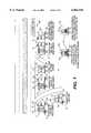
- FIG. 1is a general system diagram of the system according to a preferred embodiment of the present invention.
- FIG. 2is a system diagram illustrating the communication between the components of the system according to the present invention.
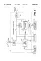
- FIG. 3is a system block diagram of the Roadside Remote Station (RRS) according to the preferred embodiment of the present invention.
- VMSportable variable message signs
- WZwork zone
- ISincident site
- At least one highway advisory radio (HAR) 14may be used to provide more detailed traffic information than can be accommodated by the VMSs 12. If there is an alternate route available, the HAR 14 can provide supplemental route navigation instructions in the event the system determines that the diversion of traffic is recommended or necessary.
- HARhighway advisory radio
- An on-site central system controller (CSC) 16is connected via a conventional communications system to control the various elements of the system 10.
- traffic sensors 18continuously acquire traffic data at multiple locations within and upstream of the work zone or incident site WZ.
- Portable ramp metering signals 20are used to limit access to the roadway during conditions of heavy congestion.
- Roadside remote stations (RRS) 22are used to receive traffic data from the sensors 18 and, under control from the CSC 16, to program the VMSs 12 to display and the HAR 14 to broadcast messages appropriate to current traffic conditions.
- RRSs 22also control the signal timing of the portable ramp metering signals 20.
- the VMSs 12, the HARs 14, the sensors 18 and the portable ramp metering signals 20may all be implemented using conventional devices used to perform their functions, such as an ADDCO Model No. DH 1000 which may be used as a VMS 12.
- An Information Station Specialists Model No. Alert AMmay be used as the HAR 14.
- Whelen Engineering Model TDW-10 sensorsmay be used for the traffic sensors 18, and the ramp metering signals 20 may be implemented using conventional traffic signals portably mounted with a RRS 22 and a power supply 242.
- the central system controller (CSC) 16may be implemented using an IBM-compatible PC or equivalent programmable data processing device with the necessary software designed to control the components of the system 10, as will be explained in more detail hereinbelow.
- the components that are physically located near one anothermay be connected to one another via conventional communication networking, such as RS-232 serial type. Those that are remotely located from one another may be communicatively connected via conventional RF transmitters and receivers in the UHF spectrum.
- conventional communication networkingsuch as RS-232 serial type.
- Those that are remotely located from one anothermay be communicatively connected via conventional RF transmitters and receivers in the UHF spectrum.
- IBM-compatible PC or equivalent programmable data processing deviceas the basis for the CSC 16 and RRSs 22 in each of the components of the system networked to the CSC 16, the system 10 is intended to operate in a completely automated fashion after its deployment and system initialization.
- an enhanced embodiment of the VMSs 12'may integrate an RRS 22 and a traffic sensor 18 with a portable VMS 12.
- the RRS 22 and traffic sensor 18may be physically mounted on the portable VMS's trailer 121 and supplied with electrical power by the portable VMS's own power source 122.
- the portable VMS 12may also serve as a mount for the RRS's communications antenna 221.
- An enhanced version of the HARs 14'may be composed of a portable HAR 14 and an RRS 22.
- the RRS 22 of an enhanced HAR 14'is physically mounted on the portable HAR's trailer 141 and is supplied with electrical power by the portable HAR's power supply 142.
- Portable ramp metering stations 20'may be formed by combining portable ramp metering signals 20 with an RRS 22 and a trailer equipped with a solar- or diesel-generator-based power supply 201.
- Supplemental speed station/repeater units (S 3 Rs) 24 for deploying additional traffic sensors 18may comprise an RRS 22, a traffic sensor 18 and a trailer 241 equipped with a solar- or diesel-generator-based power supply 242.
- the CSC 16may be located in a construction trailer 26 at the work zone WZ.
- the construction trailer 26is equipped to provide a long-term source of electrical power, security from theft and vandalism, and a benign operating environment.
- use of construction trailerstypically allows the provision of a telephone connection enabling the system 10 to be monitored and controlled remotely.
- the CSC 16is located in an environmental and security enclosure 28 mounted on a trailer 281 equipped with a solar- or diesel-generator-based power supply 282.
- This configuration for locating and enclosing the CSC 16minimizes the time necessary for deploying the CSC 16 and the system 10 as a whole.
- the selection of the components in the system 10, examples of which are described above,is intended to make every element in the system 10 portable, thereby allowing the system to be moved and re-deployed to different operating sites with minimum time and effort.
- the RRS 22is a key component of the present invention designed specifically for the implementation and operation of the system 10.
- a block diagram of the RRSis shown in FIG. 3.
- the RRS 22is supplied with nominal 12 volt DC power through the power input connection PI.
- a power filter 223removes electrical noise and protects the RRS hardware from electrical transients.
- the power filter 223supplies conditioned 12 VDC power to the radio modem 224, the power supply 225, and the traffic sensor 18 via a filtered power bus 227.
- An analog-to-digital converter (A/D) 228measures the voltage of the filtered power bus 227.
- the power supply 225converts the filtered nominal 12 VDC supplied by the filtered power bus 225 into 5 VDC to supply the single board computer circuit 229, the A/D converter 228 and a second modem 222.
- the radio modem 224is equipped with an antenna 221.
- the power supply 225is an Octagon Systems Model 7112.
- the power filter 223is implemented using conventional components known in the art.
- the radio modem 224is formed using a Motorola Model K44GNM1001A RNet 9600 baud telemetry modem.
- the A/D converter 228uses an Octagon 5720 8-bit analog input circuit.
- the single board computer circuit 229is implemented using an Octagon Systems Model 4020 circuit or equivalent.
- the antenna 221is implemented with an antenna known in the art applicable for use with the above-mentioned radio modem 224 or its equivalents, and the modem 222 is implemented using a ZOOM 2400 baud DTMF fax modem or equivalents.
- the traffic sensor 18periodically transmits traffic speeds to the single board computer 229 via an RS-232 compatible serial interface 226.
- Software running on the single board computer 229receives speed data from the traffic sensor 18 and stores it.
- the antenna 221 connected to the radio modem 224can receive radio frequency (RF) communication signals from either another RRS 22 or the central system controller 16, and conveys the RF signal to the radio modem 224, such as via an antenna cable 221a.
- the radio modem 224converts the RF signal into a serial data stream.
- the serial data from the radio modem 224is then conveyed to the single board computer 229 via the RS-232 compatible serial interface 226.
- the single board computer 229interprets the serial data stream from the radio modem 224 based on the communications protocol and the data packet format all to be explained hereinbelow.
- the serial data streams they receiveare analyzed by their single board computers 229 in order to extract the information therein, including data packet addresses. If analysis of the data packet addresses indicates that the receiving RRS is to respond, the single board computer 229 evaluates the packet's command field and performs the designated action. Valid commands and their associated actions will also be described hereinbelow.
- the single board computer 229uses an ISA bus interface 229a to program the A/D Converter 228 to select the appropriate input and return a digital value corresponding to the voltage present on the filtered power bus 227.
- the RRS 22does so using an RS-232 compatible serial interface 22a connecting it to the VMS 12.
- the RRS 22uses an ISA bus interface 22b connecting it to a modem 222 to program the modem into generating Dual-Tone-Multiple-Frequency (DTMF) tones corresponding to the characters in the data packet.
- DTMFDual-Tone-Multiple-Frequency
- the modem 222then transmits the DTMF tones to the HAR 14 via its telephone interface 222a.
- the network of RRSs 22are continuously receiving speed data from their corresponding sensors 18.
- the CSC 16acquires the traffic data from the RRSs 22 using a radio modem identical to the radio modem 224 in each RRS 22.
- the performance of the system 10is highly dependent on local topographic factors.
- the system's communications sub-systemhas demonstrated a range in excess of three miles based on the above-described implementation of the system 10.
- each of the RRSs 22is also designed to serve as a communications repeater, relaying commands to and data from RRSs 22 beyond the direct communications range of the CSC 16.
- RRSsWhen operating as communications repeaters, RRSs still receive data from their corresponding sensors 18 and can control a VMS 12, HAR 14 or ramp metering signal 20 as required.
- the CSC 16configures the communications mode of each RRS 22 during system initialization.
- RRSs 22as repeaters to relay commands and data, the system 10 can support incident sites or work zones of essentially unlimited length and of any topography.
- the system's communications protocolwhich is explained in further detail hereinbelow, is designed with a mechanism for detecting when communications have been corrupted.
- the CSC 16 or an RRS 22detects a garbled communications packet, the invalid packet is re-transmitted until it is received properly. This process insures the integrity of the system's critical data and command communications exchanges.
- the CSC 16When traffic data from the RRSs 22 is acquired by the CSC 16, the CSC analyzes the data to predict delay and to detect hazardously low speeds (e.g., speeds of less than the posted speed limit) upstream of the incident site or work area. In the event of a deterioration in traffic conditions, the CSC 22 warns drivers using the VMSs 12 and optionally one HAR 14, and if necessary regulates access to the freeway using the ramp metering signals 20.
- the CSC 16selects from several different classes of messages in memory and can combine messages as needed to describe multiple scenarios, such as simultaneous delay and hazardous speed conditions. The following message types may be stored in memory: lane closure messages; speed advisory messages; delay messages; diversion messages; and time-stamp messages. In addition to its automated VMS message selection mode, as controlled by the CSC 16, the system 10 allows manual entry of messages for special circumstances.
- the speed advisory and delay messagescan be very specific, enhancing credibility.
- the CSC 16is programmed with templates for each speed advisory and delay message and "fills-in" the message with the appropriate speed or delay information based on the current traffic data that it receives and processes. For example, when the system 10 detects modest levels of congestion (e.g., 5 minutes ), the CSC 16 will output the necessary data to selected RRSs 22 in order to program the appropriate VMSs 12 to display the delay and speed advisory messages as shown below:
- the actual level of delay and advisory speed presented by the systemis derived from the current traffic conditions data. If, to continue from the previous example, traffic conditions were detected as deteriorating further, the CSC 16 will process the traffic data describing the deteriorating conditions and then transmit the necessary data to adjust the messages as shown below:
- the CSC 16may then output the necessary data to the appropriate RRSs 22 for programming a HAR 14 to transmit the appropriate messages recommending that drivers divert to an alternate route and even supplying route navigation instructions.
- An example VMS diversion messageis shown below:
- Each VMS 12may be programmed to display one or more of the message types, and different VMSs within the same network may display different message types.
- the CSC 16selects messages for each VMS 12 independently, based on the current traffic speed downstream of the selected VMS, the predicted delay for the work zone or incident site as a whole, and the message types currently enabled on the selected VMS. Having determined the appropriate messages for the system's VMSs 12 and HAR 14, the CSC 16 will command the RRSs 22 controlling the corresponding equipment to update their messages if required.
- VMS and HAR messagesare time-stamped; that is, they contain elements that specify when the message was last updated.
- the systemautomatically updates these messages.
- An example VMS speed advisory message and it's associated time-stamp messageis shown below:
- the RRSs 22are designed to operate with solar-powered VMSs and HARs, thereby minimizing the level of maintenance required by the system in terms of having to replenish the power supplies of the individual components in the system 10.
- the supplemental speed station/repeater units 24 and portable ramp metering stations 20also utilize solar energy power supplies. Since the availability of power produced by solar panels is affected by both the level and duration of sunlight, systems that rely on solar power are vulnerable to service interruptions due to cloudy weather or the reduction in the number of daylight hours during winter.
- the CSC 16To insure continuous operation of the system during times of low solar power output (e.g., dark or overcast days), the CSC 16 periodically commands each RRS 22 to measure its battery voltage. RRSs whose battery voltage is low are flagged by the CSC 16, whereby the necessary warnings are relayed to operators monitoring the system. Maintenance crews can then be dispatched to the flagged RRSs to either replace or recharge their batteries before the equipment shuts down.
- the central system controller (CSC) 16communicates with the remote roadside stations (RRSs) 22 through the exchange of data packets via wireless modems.
- the format of these data packetsis shown in detail hereinbelow.
- communication between the CSC 16 and the RRSs 22is half duplex.
- the CSC 16 and each of the RRSs 22has a unique network address.
- the address of the CSCis always 0, while the address of the deployed RRSs may range from 1 to 127.
- Each RRSis assigned an address during an initial system setup conducted by the CSC, and stores that address in non-volatile memory.
- the CSC 16When, in the operation of its program, the CSC 16 is directed to retrieve traffic sensor data from an RRS 22 or change the output of a device (i.e., a VMS or HAR) connected to an RRS, the CSC 16 will build a command packet, address the data packet to the target RRS 22, and then transmit the data packet.
- a devicei.e., a VMS or HAR
- all of the RRSs 22will receive the transmitted command packet(s) through their wireless radio modems 224 and process those data packets accordingly.
- those RRSs 22 to which a particular data packet is not addressedwill discard the packet without further processing.
- the RRS 22, to which a data packet is addressedwill transmit a response signal back to the CSC 16 to indicate either that the data packet has been properly received or that the data packet should be re-transmitted.
- the CSC 16will not transmit a second command packet for that unit until it receives a response to the first command packet or until after an no-response time period activated by the CSC 16 expires.
- a RRS 22will evaluate the addresses in the FDEST and IDEST fields of the data packet to determine what processing, if any, it should perform. In general, there are three kinds of packet processing an RRS 22 may perform. If the addresses in both the FDEST and IDEST fields match the address of the RRS, the data packet is thereby determined as being intended specifically for that RRS. The RRS will then execute the command specified in the packet's CMD field and transmit a reply packet with the results of the operation.
- the RRSwill discard the packet without implementing the command or replying.
- the RRSmust re-transmit the packet without processing it, if it is configured to do so. This is referred to as repeater operation and is discussed in the following section.
- the RRS 22 to which the packet is addressedwill validate it. This validation takes the form of a CRC calculation on the packet, packet parameter consistency checks and verification of the RRS's internal state or configuration (i.e., repeater status, attached device type, etc.). If the packet passes the CRC check and other tests, the RRS 16 will process and perform the command specified in the CMD field of the data packet, and then transmit a reply packet with its CMDSTAT field set appropriately.
- one or several RRSs 22may be beyond the range of direct communication with the CSC 16 or beyond within line-of-sight of the CSC 16 (See FIG. 2).
- an intermediate RRS 22is configured for repeater operation; that is, for re-transmitting command and data packets.
- the CSC 16can communicate with RRSs 16 beyond the maximum line-of-sight range.
- operation as a repeaterdoes not limit the operation of a RRS in any way; it still responds to command packets directed to it as would RRSs not configured as repeaters.
- a data packet's IDEST fieldindicates the address of the next unit that should handle the packet.
- a repeater RRS 22In order to act as an intermediary in the communication between the CSC 16 and another RRS 22, a repeater RRS 22 must receive a data packet whose IDEST field matches its own address, and then transmit the packet to the next RRS 22 in the "chain" connecting the CSC 16 to the final destination RRS 22 designated by the FDEST field.
- RRSs 22 acting as repeatersuse a structure called a remap table, internal to its software, to re-address data packets prior to re-transmission.
- the remap tableis the key to repeater operation since, taken as a whole, the remap tables of the repeater RRSs 22 describe the IDEST address path to those RRSs 22 not in direct communication with the CSC 16.
- an RRS 22Once an RRS 22 is commanded into repeater mode and its remap table is loaded from the CSC 16, it will relay command and reply packets by replacing the address in the IDEST field of the data packet (which initially will be its own address) with the value extracted from its remap table using the FDEST address as an index.
- This addressmay be that of the final destination RRS or another repeater RRS, depending on the geometry of the RRSs deployed in the system 10. So that a data packet's next intended recipient knows to whom to send a reply signal, the repeater RRS also replaces the address in the SENDER field of the data packet with its own.
- the ORG field of the data packetwhich indicates the address of the originator of the packet, remains unchanged. The repeater RRS 22 will then transmit the modified packet.
- the following example as illustrated in FIG. 2shows communication between the CSC 16 and a RRS 22 having an address #6 using the RRSs 22 at addresses #3 and #5 as repeaters.
- the CSC 16determine the proper value of the IDEST field in its own remap table stored in its software, so that the data packet will be transmitted to a repeater RRS if required.
- the CSC's remap tablelooks like the following:
- the CSC 16Since the first element in the remap table is the element for address #0, the CSC 16 extracts element 6 (for the corresponding RRS address) from the table and inserts that address into the IDEST field of the data packet. In this example, the CSC 16 inserts the address of RRS #3. This insures that the packet will be routed to repeater RRS #3 first.
- the packet transmitted by the CSC 16will then be configured as follows:
- RRS #3was configured as a repeater; its remap table will appear as follows, as an example:
- repeater RRS #3modifies the packet and re-transmits it. So that the recipient knows to whom to reply, RRS #3 inserts its address into the SENDER field. Next, it extracts the new address for the IDEST field from entry 6 (the value of the FDEST field in the original) of its remap table. The modified packet will then appear as follows:
- RRS #5was also configured as a repeater; its remap table will have been configured as follows, as an example:
- repeater RRS #5modifies it and re-transmits it. So that the recipient knows to whom to reply, RRS #5 inserts its address into the SENDER field. Next, it extracts the new address for the IDEST field from entry 6 (the FDEST field) of its remap table.
- the modified packetwill therefore be configured as follows:
- RRS #6evaluates the data packet after receiving it from repeater RRS #5. Since both the FDEST and IDEST fields match its own address, RRS #6 validates the packet then executes the command within it. RRS #6 then transmits a reply data packet based on the results of executing the command from the CSC. That reply packet will appear as follows:
- repeater RRS #5modifies it and re-transmits it. So that the recipient knows where it came from, RRS #5 inserts its address into the SENDER field of the reply packet. Next, it extracts the new address for the IDEST field from entry 0 (the FDEST field) of its remap table.
- the modified packetwill appear as follows:
- repeater RRS #3modifies it and re-transmits it. So that the recipient knows where it came from, RRS #3 inserts its address into the SENDER field of the reply packet. Next, it extracts the new address for the IDEST field from entry 0 (the FDEST field) of its remap table. This next modified packet will appear as follows:
- communication between the CSC 16 and the network of RRSs 22 in the system 10is accomplished using a specific data packet format, wherein the necessary address and command data are inserted in order to implement the necessary data transfers between the CSC 16 and designated RRSs and between RRSs.
- a specific data packet formatwherein the necessary address and command data are inserted in order to implement the necessary data transfers between the CSC 16 and designated RRSs and between RRSs.
- the Start of Message Fieldis used to indicate the beginning of a packet. This byte will always have the value 0 ⁇ A5.
- the final destination fieldindicates the address of the device which is to process the packet.
- Valid valuesare 0 (for an RRS replying to the CSC) and 1 through 127 (for an RRS command packet sent by the CSC).
- the intermediate destination fieldindicates the address of the next device to handle the packet, but not necessarily the device to process it. This field is used for communicating via repeater RRSs. This field is set equal to the FDEST field when the packet is transmitted to its final destination. Valid values are 0 (for an RRS replying to the CSC) and 1 through 127 (for an RRS command packet sent by the CSC).
- the SENDER fieldcontains the address of the device that transmitted the packet. This may not be the same device that originated the packet if two devices are communicating via repeater RRSs. Valid values range are 0 (for an RRS command packet sent by the CSC) and 1 through 127 (for an RRS replying to the CSC).
- This fieldcontains the address of the first device to transmit the packet (the originator of the packet). This may not be the same device that most recently transmitted the packet if two devices are communicating via repeater RRSs. Valid values are 0 (for an RRS command packet sent by the CSC) and 1 through 127 (for an RRS replying to the CSC).
- the command fieldcontains a code corresponding to the operation the RRS is to perform. These command codes are defined in detail in Table 1 in the accompanying specification.
- the CMDSTAT byteis returned by the RRS and represents the results of processing the last command packet intended for it.
- the byteis organized as a bit field; only one bit may be set at a time. Successful completion is indicated by returning a 0 in this field.
- the CMDSTAT byteis defined as follows:
- bit fields within the CMDSTAT byteare arranged in hierarchical order with bit 7 being the most severe error. For example, a 1 in bit 4 (Configuration Error) implies that the packet was received when the RRS was not busy, that the packet's CRC was correct, and that the value in the CMD field was legal.
- the RRSwill reply without performing any further operations.
- the RRSwill clear the RESET bit it reports in the RRSSTAT byte.
- CMD 40Configure Serial Port
- the RRSwill configure the serial port indicated by byte 12 as specified in byte 13 as follows, provided that byte 12 does not specify the port connected to the RRS's RF modem:
- CMD 50Write Data to Serial Port
- the RRSwill copy the data string starting in byte 13 of the data section of the command packet to the serial port specified in byte 12 provided that byte 12 does not specify the port connected to the RRS's RF modem.
- the length of the datais equal to byte 9 of the packet (DATALEN) minus 1.
- the datamust be no longer than 243 bytes.
- the RRSwill use the remap table in the data bytes to act as a repeater, indicating this status through bit 7 of the RRSSTAT field.
- DATA fieldRemap table: packet byte 12 corresponds to the IDEST field for the unit at address 0 (the CSC), packet byte 13 corresponds to the network address 1, etc.
- CMD 61Cancel Repeater Status
- the RRSno longer acts as a repeater; it also clears bit 7 of its RRSSTAT field.
- CMD 91Select Active Traffic Data Buffer
- This commandcontrols the destination of incoming traffic data from the sensor connected to the RRS.
- the RRSWhen the RRS powers up, it will arbitrarily designate one of its two traffic data buffers as buffer 0 and the other as buffer 1. Buffer 0 will be the first active buffer and buffer 1 the initial inactive buffer. All incoming traffic data will be routed to the buffer currently designated as the active buffer.
- Reception of command 110causes the RRS to return the contents of the inactive buffer.
- the RRSUpon reception of a valid Select Active Traffic Data Buffer command, the RRS shall re-initialize the traffic buffer designated in byte 13 and utilize it as the active buffer until otherwise directed. By definition, the other traffic data buffer becomes the inactive buffer
- DATA fieldID of active traffic data buffer (0 or 1)
- This commandreturns radar sensor speed data from the RRS's currently inactive traffic data buffer.
- a hexadecimal word(two bytes) representing the number of speed data points used in calculating the average speed reported in byte 12.
- Byte 13is the MSB; byte 14 the LSB.
- the ID of the buffer from which the data was retrieved(0 or 1).
- This commandcauses the RRS to measure and return the DC voltage present at its 12 VDC power connector.
- DATA fieldOne byte representing the input power voltage in units of 60 mV.
- DATA field lengthVariable, but less than 32
- DATA fieldA null-terminated ASCII string containing the version number and date
- CMD 210Return Extended Statistics
- This commandresets the RRS as if it had been powered-up.
Landscapes
- Life Sciences & Earth Sciences (AREA)
- Atmospheric Sciences (AREA)
- Physics & Mathematics (AREA)
- General Physics & Mathematics (AREA)
- Traffic Control Systems (AREA)
Abstract
Description
______________________________________ Delay Message Speed Advisory Message ______________________________________ 5 MIN SLOW TO DELAY 40 MPH AHEAD **NOW** ______________________________________
______________________________________ Delay Message Speed Advisory Message ______________________________________ 15 MIN SLOW TO DELAY 25 MPH AHEAD **NOW** ______________________________________
______________________________________ Phase 1Phase 2 ______________________________________ ALT TUNE ROUTE RADIO EXIT 19 530 AM ______________________________________
______________________________________ Phase 1Phase 2 ______________________________________ ROADWORK SLOW TO ADVISORY 25 MPH 2:24 PM **NOW** ______________________________________
______________________________________ Remap Table Explanation ______________________________________ 0 Not used, we won't be talking to ourselves. 1 We're in direct communication withRRS # 1. 2 We're in direct communication withRRS # 2. 3 We're in direct communication withRRS # 3. 4 We're NOT in direct communication withRRS # 4. Send its packets toRRS # 3 first. (RRS # 3 is a repeater) 5 We're NOT in direct communication withRRS # 5. Send its packets toRRS # 3 first. (RRS # 3 is a repeater) 6 We're NOT in direct communication withRRS # 6. Send its packets toRRS # 3 first. (RRS # 3 is a repeater) -- (We're not in direct communication with any RRSpast # 3. Packets for anRRS past # 3 must be sent toRRS # 3 first, so the remaining 121 entries are also # 3.) ______________________________________
______________________________________ Command Packet Sent by CSC Description ______________________________________ SOM 0 × A5 always 0 ×A5 FDEST 6 final destination isRRS # 6IDEST 3 but packet goes toRRS # 3 first SENDER 0 transmitted by the CSC ORG 0 originated by the CSC (remaining fields omitted for clarity) ______________________________________
______________________________________ IDEST Address Explanation ______________________________________ 0 We're in direct communication with the CSC. Any inbound replies get transmitted to it directly. 1 We're in direct communication withRRS # 1. 2 We're in direct communication withRRS # 2. 3 We're in direct communication withRRS # 3. 4 We're in direct communication withRRS # 4. 5 We're in direct communication withRRS # 5. 6 We're NOT in direct communication withRRS # 6. Send its packets toRRS # 5 first. (RRS # 5 is a repeater) -- (We're not in direct communication with any RRSpast # 6. Packets for anRRS past # 6 must be sent toRRS # 3 first, so the remaining 120 entries are also #5.) ______________________________________
______________________________________ Command Packet Re- transmitted byRRS # 3 Description ______________________________________ SOM 0 × A5 always 0 ×A5 FDEST 6 final destination isRRS # 6IDEST 5 but packet goes toRRS # 5next SENDER 3 transmitted byRRS # 3 ORG 0 originated by CSC (remaining fields omitted for clarity) ______________________________________
______________________________________ IDEST Address Explanation ______________________________________ 0 We're NOT in direct communication with the CSC. Send its packets toRRS # 3 first. (RRS # 3 is a repeater) 1 We're NOT in direct communication withRRS # 1. Send its packets toRRS # 3 first. (RRS # 3 is a repeater) 2 We're NOT in direct communication withRRS # 2. Send its packets toRRS # 3 first. (RRS # 3 is a repeater) 3 We're in direct communication withRRS # 3. 4 We're in direct communication withRRS # 4. 5 We're in direct communication withRRS # 5. 6 We're in direct communication withRRS # 6. -- (We're not in direct communication with any RRSpast # 6. Packets for anRRS past # 6 must be sent toRRS # 3 first, so the remaining 120 entries are also #6.) ______________________________________
______________________________________ Command Packet Re- transmitted byRRS 5 Description ______________________________________ SOM 0 × A5 always 0 ×A5 FDEST 6 final destination isRRS # 6IDEST 6 packet goes toRRS # 6next SENDER 5 transmitted byRRS # 3 ORG 0 originated by CSC (remaining fields omitted for clarity) ______________________________________
______________________________________ Reply Packet Sent byRRS 6 Description ______________________________________ SOM 0 × A5 always 0 × A5 FDEST 0 final destination is CSC (ORG field in command packet)IDEST 5 but packet goes toRRS 5 first (SENDER field in command packet)SENDER 6 transmitted byRRS # 6ORG 6 originated by RRS #6 (remaining fields omitted for clarity) ______________________________________
______________________________________ Reply Packet Re- transmitted byRRS 5 Description ______________________________________ SOM 0 × A5 always 0 × A5 FDEST 0 final destination isCSC IDEST 3 but packet goes toRRS # 3next SENDER 5 transmitted byRRS # 5ORG 6 originated by RRS #6 (remaining fields omitted for clarity) ______________________________________
______________________________________ Reply Packet Re- transmitted byRRS 3 Description ______________________________________ SOM 0 × A5 always 0 × A5 FDEST 0 final destination is CSC IDEST 0 and that's where it's goingnext SENDER 3 transmitted byRRS # 3ORG 6 originated by RRS #6 (remaining fields omitted for clarity ______________________________________
______________________________________ System Data Packet Format Byte # Msg Field Description ______________________________________ 0 SOM Start Of Message, always 0 ×A5 1 FDEST Address of CSC (reply packet) or RRS for which this packet is ultimately intended (command packet) 2 IDEST Address of next RRS to handle thispacket 3 SENDER Address of RRS or CSC that transmitted thispacket 4 ORG Address ofpacket originator 5 CMDRRS command opcode 6 CMDSTAT Bit mapped status field, refers to processing of last packet received. Set to 0 by CSC, set appropriately by RRS when replying. 7 RRSSTAT Bit mapped status field, refers to current state of RRS. Set to 0 by CSC; set appropriately by RRS when replying. 8 MSGCNT Set by CSC to reflect running total of messages transmitted; transmitted without modification by the RRS 9 DATALEN Total number of DATA bytes in thispacket 10 CRCMSB Most significant byte of packet CRC 11 CRCLSB Least significant byte of packet CRC 12-225 DATA Optional variable length CMD-code-dependent information ______________________________________
______________________________________ CMDSTAT Byte Bit 7Bit 6Bit 5Bit 4Bit 3Bit 2 Bit l Bit 0 ______________________________________ RRS CRC CMD Configu- Invalid Device Health Set busy error out of ration Para- Did Not Test Device range Error meter Respond Error Type Error ______________________________________
______________________________________ RRS Command Opcodes CMD field Description ______________________________________ 0 NOP - no operation 30 Clear RESET bit in RRSSTAT field 40 Configure serial port 50 Write data to serial port 60 Become repeater, remap list attached 61 Cancel repeater status 91 Select active traffic data buffer 105 Return radar sensor speed data 180 Return input power voltage 200 Return RRS version 210 Retrieve extended statistics 215 Reset extended statistics 255 Reset RRS ______________________________________
______________________________________ Bit 7Bit 6Bit 5Bit 4Bit 3Bit 2Bit 1 Bit 0 ______________________________________ Baud Baud Baud Data DataParity Parity Stop 2 1 0Bits 1 Bits 0 1 0 Bits ______________________________________
______________________________________ Bit 4Bit 3 Data Bits ______________________________________ 0 0 8 0 1 7 1 0 undefined 1 1 undefined ______________________________________ Bit 7Bit 6Bit 5 Baud Rate ______________________________________ 0 0 0 300 0 0 1 1200 0 1 0 2400 0 1 1 4800 1 0 0 9600 1 0 1 19200 1 1 0 Undefined 1 1 1Undefined ______________________________________ Bit 2Bit 1 Parity ______________________________________ 0 0 None 0 1 Undefined 1 0 Even 1 1 Odd ______________________________________ Bit 0 Stop Bits ______________________________________ 0 1 1 2 ______________________________________
Claims (50)
Priority Applications (1)
| Application Number | Priority Date | Filing Date | Title |
|---|---|---|---|
| US08/873,239US6064318A (en) | 1997-06-11 | 1997-06-11 | Automated data acquisition and processing of traffic information in real-time system and method for same |
Applications Claiming Priority (1)
| Application Number | Priority Date | Filing Date | Title |
|---|---|---|---|
| US08/873,239US6064318A (en) | 1997-06-11 | 1997-06-11 | Automated data acquisition and processing of traffic information in real-time system and method for same |
Publications (1)
| Publication Number | Publication Date |
|---|---|
| US6064318Atrue US6064318A (en) | 2000-05-16 |
Family
ID=25361237
Family Applications (1)
| Application Number | Title | Priority Date | Filing Date |
|---|---|---|---|
| US08/873,239Expired - LifetimeUS6064318A (en) | 1997-06-11 | 1997-06-11 | Automated data acquisition and processing of traffic information in real-time system and method for same |
Country Status (1)
| Country | Link |
|---|---|
| US (1) | US6064318A (en) |
Cited By (84)
| Publication number | Priority date | Publication date | Assignee | Title |
|---|---|---|---|---|
| US6252522B1 (en)* | 1998-05-28 | 2001-06-26 | Solana Technology Development Corporation | Billboard consumption measurement system |
| US20020027504A1 (en)* | 1999-03-18 | 2002-03-07 | James Davis | System and method for controlling communication between a host computer and communication devices associated with remote devices in an automated monitoring system |
| US6477459B1 (en)* | 1999-03-27 | 2002-11-05 | Robert Bosch Gmbh | Method for informing motor vehicle drivers |
| US6559774B2 (en)* | 2001-04-06 | 2003-05-06 | International Road Dynamics Inc. | Dynamic work zone safety system and method |
| US6636801B2 (en)* | 2001-04-23 | 2003-10-21 | Sun Microsystems, Inc. | Delivering location-dependent services to automobiles |
| US20040130463A1 (en)* | 2003-01-03 | 2004-07-08 | David Bloomquist | Autonomous highway traffic modules |
| US20040158336A1 (en)* | 2001-08-02 | 2004-08-12 | Alonso Daniel Cuende | System for automatically locating visibility zones |
| US20050129410A1 (en)* | 2003-12-12 | 2005-06-16 | Clifton Labs, Inc. | Vehicular optical communications system |
| US6915107B1 (en) | 2002-03-25 | 2005-07-05 | Florida Digital Technologies, Inc. | Revenue generating method of broadcasting on FM subcarrier |
| US20050221816A1 (en)* | 2004-03-31 | 2005-10-06 | Hall Thomas M | System for and method of operating a radio station in a broadcast network |
| US20050231385A1 (en)* | 2004-04-15 | 2005-10-20 | 3M Innovative Properties Company | Methods and systems utilizing a programmable sign display located in proximity to a traffic light |
| WO2006008825A1 (en) | 2004-07-16 | 2006-01-26 | Fourie | Road condition informing system and road condition informing method |
| US20060038702A1 (en)* | 2004-02-27 | 2006-02-23 | Lo Teddy Y M | Led traffic light |
| US20060071814A1 (en)* | 2004-10-04 | 2006-04-06 | Richard Cummings | Stop alert warining system |
| US7079810B2 (en) | 1997-02-14 | 2006-07-18 | Statsignal Ipc, Llc | System and method for communicating with a remote communication unit via the public switched telephone network (PSTN) |
| US7103511B2 (en) | 1998-10-14 | 2006-09-05 | Statsignal Ipc, Llc | Wireless communication networks for providing remote monitoring of devices |
| US7137550B1 (en) | 1997-02-14 | 2006-11-21 | Statsignal Ipc, Llc | Transmitter for accessing automated financial transaction machines |
| US20060270424A1 (en)* | 2005-05-31 | 2006-11-30 | Benco David S | Network support for remote sign content update |
| US20060278705A1 (en)* | 2003-02-21 | 2006-12-14 | Accenture Global Services Gmbh | Electronic Toll Management and Vehicle Identification |
| US20070008178A1 (en)* | 2004-02-27 | 2007-01-11 | Lo Teddy Y M | Interactive bulletin board system and method |
| US20070115139A1 (en)* | 2005-11-18 | 2007-05-24 | Emergency Traffic Systems, Inc. | Traffic signal devices and methods of using the same |
| US20070118273A1 (en)* | 2005-11-21 | 2007-05-24 | Wai-Cheung Tang | Method and system for obtaining traffic information using transponders |
| US7263073B2 (en) | 1999-03-18 | 2007-08-28 | Statsignal Ipc, Llc | Systems and methods for enabling a mobile user to notify an automated monitoring system of an emergency situation |
| US7295128B2 (en) | 1998-06-22 | 2007-11-13 | Sipco, Llc | Smoke detection methods, devices, and systems |
| US20070265734A1 (en)* | 2006-04-07 | 2007-11-15 | Clark Christopher M | Traffic information system |
| US20070299595A1 (en)* | 2006-06-23 | 2007-12-27 | Anthony Boldin | Traffic control system and method |
| US20080040210A1 (en)* | 2006-04-14 | 2008-02-14 | Accenture Global Services Gmbh | Electronic toll management for fleet vehicles |
| US7397907B2 (en) | 1997-02-14 | 2008-07-08 | Sipco, Llc | Multi-function general purpose transceiver |
| US7424527B2 (en) | 2001-10-30 | 2008-09-09 | Sipco, Llc | System and method for transmitting pollution information over an integrated wireless network |
| CN100429905C (en)* | 2004-02-09 | 2008-10-29 | 西安美太信息有限公司 | Traffic information automatic acquisition and management method |
| US20080303642A1 (en)* | 2007-03-14 | 2008-12-11 | Jolley Mark W | Apparatus and Method for Remotely Obtaining and Evaluating Vehicular and Other Information |
| US7480501B2 (en) | 2001-10-24 | 2009-01-20 | Statsignal Ipc, Llc | System and method for transmitting an emergency message over an integrated wireless network |
| US20090146845A1 (en)* | 2003-02-21 | 2009-06-11 | Accenture Global Services Gmbh | Electronic toll management |
| US20100026520A1 (en)* | 2005-11-18 | 2010-02-04 | Emergency Traffic Systems, Inc. | Traffic signal devices and methods of using the same |
| US7697492B2 (en) | 1998-06-22 | 2010-04-13 | Sipco, Llc | Systems and methods for monitoring and controlling remote devices |
| US7729850B1 (en)* | 2002-09-30 | 2010-06-01 | Kraft Clifford H | System and method of providing real-time road construction information for vehicle trip planning |
| US7756086B2 (en) | 2004-03-03 | 2010-07-13 | Sipco, Llc | Method for communicating in dual-modes |
| US20100225502A1 (en)* | 2009-03-09 | 2010-09-09 | Mohamed Roshdy Elsheemy | Colored LED traffic light display |
| US20100228607A1 (en)* | 2005-06-10 | 2010-09-09 | Accenture Global Services Gmbh | Electric toll management |
| US20110109475A1 (en)* | 2009-11-12 | 2011-05-12 | Gm Global Technology Operations, Inc. | Travel Lane Advisor |
| US8000314B2 (en) | 1996-12-06 | 2011-08-16 | Ipco, Llc | Wireless network system and method for providing same |
| US20110199231A1 (en)* | 2010-02-12 | 2011-08-18 | Vincent Loiselle | Traffic management system |
| US8013732B2 (en) | 1998-06-22 | 2011-09-06 | Sipco, Llc | Systems and methods for monitoring and controlling remote devices |
| US8031650B2 (en) | 2004-03-03 | 2011-10-04 | Sipco, Llc | System and method for monitoring remote devices with a dual-mode wireless communication protocol |
| US8064412B2 (en) | 1998-06-22 | 2011-11-22 | Sipco, Llc | Systems and methods for monitoring conditions |
| US8410931B2 (en) | 1998-06-22 | 2013-04-02 | Sipco, Llc | Mobile inventory unit monitoring systems and methods |
| US8489063B2 (en) | 2001-10-24 | 2013-07-16 | Sipco, Llc | Systems and methods for providing emergency messages to a mobile device |
| US8787246B2 (en) | 2009-02-03 | 2014-07-22 | Ipco, Llc | Systems and methods for facilitating wireless network communication, satellite-based wireless network systems, and aircraft-based wireless network systems, and related methods |
| US8819313B1 (en) | 2013-07-19 | 2014-08-26 | Superior Traffic Systems, LLC | Traffic management system |
| US8996286B1 (en)* | 2012-08-03 | 2015-03-31 | Google Inc. | Method for analyzing traffic patterns to provide solutions for alleviating traffic problems |
| US9129526B2 (en) | 2013-07-19 | 2015-09-08 | Superior Traffic Sysems, LLC | Traffic management system |
| US9135817B2 (en) | 2013-07-19 | 2015-09-15 | Superior Traffic Systems, LLC | Traffic management system |
| CN104963260A (en)* | 2015-06-10 | 2015-10-07 | 山东省交通科学研究院 | Rut preventing device and method for long uphill section of asphalt pavement |
| US20150350748A1 (en)* | 2014-05-27 | 2015-12-03 | International Business Machines Corporation | Cooperative task execution in instrumented roadway systems |
| WO2016137942A1 (en)* | 2015-02-23 | 2016-09-01 | GE Lighting Solutions, LLC | Control of a traffic signaling system and remote control of light signaling devices such as traffic heads |
| US9439126B2 (en) | 2005-01-25 | 2016-09-06 | Sipco, Llc | Wireless network protocol system and methods |
| US9453309B2 (en)* | 2014-09-12 | 2016-09-27 | Intel Corporation | Technologies for communicating roadway information |
| JP2016181309A (en)* | 2016-07-22 | 2016-10-13 | セフテック株式会社 | Congestion alarm device and congestion alarm system |
| US9626650B2 (en) | 2011-04-14 | 2017-04-18 | Elwha Llc | Cost-effective resource apportionment technologies suitable for facilitating therapies |
| US9852622B2 (en)* | 2014-09-05 | 2017-12-26 | Purdue Research Foundation | Methods and systems for real-time advanced congestion identification and warning |
| WO2018071318A1 (en)* | 2016-10-10 | 2018-04-19 | Westinghouse Air Brake Technologies Corporation | System, method, and apparatus for verifying railroad work zone instructions |
| US10445846B2 (en) | 2011-04-14 | 2019-10-15 | Elwha Llc | Cost-effective resource apportionment technologies suitable for facilitating therapies |
| WO2020014227A1 (en)* | 2018-07-10 | 2020-01-16 | Cavh Llc | Route-specific services for connected automated vehicle highway systems |
| US10540890B2 (en)* | 2016-12-12 | 2020-01-21 | Toyota Jidosha Kabushiki Kaisha | Construction-related information estimation system |
| US10692365B2 (en) | 2017-06-20 | 2020-06-23 | Cavh Llc | Intelligent road infrastructure system (IRIS): systems and methods |
| US10867512B2 (en) | 2018-02-06 | 2020-12-15 | Cavh Llc | Intelligent road infrastructure system (IRIS): systems and methods |
| USRE48781E1 (en) | 2001-09-27 | 2021-10-19 | Wavetronix Llc | Vehicular traffic sensor |
| US11373122B2 (en) | 2018-07-10 | 2022-06-28 | Cavh Llc | Fixed-route service system for CAVH systems |
| US11380193B2 (en)* | 2017-10-20 | 2022-07-05 | Zendrive, Inc. | Method and system for vehicular-related communications |
| US11495126B2 (en) | 2018-05-09 | 2022-11-08 | Cavh Llc | Systems and methods for driving intelligence allocation between vehicles and highways |
| US11639188B2 (en) | 2016-10-10 | 2023-05-02 | Westinghouse Air Brake Technologies Corporation | Work zone instruction verification system |
| CN116189432A (en)* | 2023-02-15 | 2023-05-30 | 浙江中控信息产业股份有限公司 | Traffic accident regulation and control method and regulation and control system |
| US11735035B2 (en) | 2017-05-17 | 2023-08-22 | Cavh Llc | Autonomous vehicle and cloud control (AVCC) system with roadside unit (RSU) network |
| US11775010B2 (en) | 2019-12-02 | 2023-10-03 | Zendrive, Inc. | System and method for assessing device usage |
| US11842642B2 (en) | 2018-06-20 | 2023-12-12 | Cavh Llc | Connected automated vehicle highway systems and methods related to heavy vehicles |
| US11871313B2 (en) | 2017-11-27 | 2024-01-09 | Zendrive, Inc. | System and method for vehicle sensing and analysis |
| US11878720B2 (en) | 2016-12-09 | 2024-01-23 | Zendrive, Inc. | Method and system for risk modeling in autonomous vehicles |
| US12057011B2 (en) | 2018-06-28 | 2024-08-06 | Cavh Llc | Cloud-based technology for connected and automated vehicle highway systems |
| US12056633B2 (en) | 2021-12-03 | 2024-08-06 | Zendrive, Inc. | System and method for trip classification |
| US20240321094A1 (en)* | 2023-03-22 | 2024-09-26 | Jose Arrieta | Hands-Free Device and System for Real Time Notifications for Runaway Ramps and Exits |
| US12192865B2 (en) | 2016-09-12 | 2025-01-07 | Credit Karma, Llc | Method for mobile device-based cooperative data capture |
| US12219445B2 (en) | 2018-07-10 | 2025-02-04 | Cavh Llc | Vehicle on-board unit for connected and automated vehicle systems |
| US12230073B2 (en) | 2013-03-12 | 2025-02-18 | Credit Karma, Llc | System and method for determining a driver in a telematic application |
| US12400272B2 (en) | 2019-12-02 | 2025-08-26 | Credit Karma, Llc | System and method for assessing device usage |
Citations (8)
| Publication number | Priority date | Publication date | Assignee | Title |
|---|---|---|---|---|
| US5214793A (en)* | 1991-03-15 | 1993-05-25 | Pulse-Com Corporation | Electronic billboard and vehicle traffic control communication system |
| US5231393A (en)* | 1988-10-18 | 1993-07-27 | P.A.T., Co. | Mobile speed awareness device |
| US5257020A (en)* | 1991-06-12 | 1993-10-26 | Fiber-Optics Sales Co., Inc. | Variable message traffic signalling trailer |
| US5617086A (en)* | 1994-10-31 | 1997-04-01 | International Road Dynamics | Traffic monitoring system |
| US5673039A (en)* | 1992-04-13 | 1997-09-30 | Pietzsch Ag | Method of monitoring vehicular traffic and of providing information to drivers and system for carring out the method |
| US5710554A (en)* | 1996-02-01 | 1998-01-20 | Pettler; Peter R. | Pavement ice detector |
| US5729214A (en)* | 1996-01-02 | 1998-03-17 | Moore; Steven Jerome | Condition reactive display medium |
| US5900826A (en)* | 1996-11-27 | 1999-05-04 | Farber; Gary J. | Remote controlled portable traffic signals |
- 1997
- 1997-06-11USUS08/873,239patent/US6064318A/ennot_activeExpired - Lifetime
Patent Citations (9)
| Publication number | Priority date | Publication date | Assignee | Title |
|---|---|---|---|---|
| US5231393A (en)* | 1988-10-18 | 1993-07-27 | P.A.T., Co. | Mobile speed awareness device |
| US5214793A (en)* | 1991-03-15 | 1993-05-25 | Pulse-Com Corporation | Electronic billboard and vehicle traffic control communication system |
| US5257020A (en)* | 1991-06-12 | 1993-10-26 | Fiber-Optics Sales Co., Inc. | Variable message traffic signalling trailer |
| US5257020C1 (en)* | 1991-06-12 | 2002-08-13 | Fiber Optics Sales Co Inc | Variable message traffic signalling trailer |
| US5673039A (en)* | 1992-04-13 | 1997-09-30 | Pietzsch Ag | Method of monitoring vehicular traffic and of providing information to drivers and system for carring out the method |
| US5617086A (en)* | 1994-10-31 | 1997-04-01 | International Road Dynamics | Traffic monitoring system |
| US5729214A (en)* | 1996-01-02 | 1998-03-17 | Moore; Steven Jerome | Condition reactive display medium |
| US5710554A (en)* | 1996-02-01 | 1998-01-20 | Pettler; Peter R. | Pavement ice detector |
| US5900826A (en)* | 1996-11-27 | 1999-05-04 | Farber; Gary J. | Remote controlled portable traffic signals |
Non-Patent Citations (1)
| Title |
|---|
| Smart Work Zone, ADDCO Portable Work Zone Safety System Components specification document; ADDCO, St. Paul, Minnesota.* |
Cited By (166)
| Publication number | Priority date | Publication date | Assignee | Title |
|---|---|---|---|---|
| US8000314B2 (en) | 1996-12-06 | 2011-08-16 | Ipco, Llc | Wireless network system and method for providing same |
| US8982856B2 (en) | 1996-12-06 | 2015-03-17 | Ipco, Llc | Systems and methods for facilitating wireless network communication, satellite-based wireless network systems, and aircraft-based wireless network systems, and related methods |
| US8625496B2 (en) | 1996-12-06 | 2014-01-07 | Ipco, Llc | Wireless network system and method for providing same |
| US8233471B2 (en) | 1996-12-06 | 2012-07-31 | Ipco, Llc | Wireless network system and method for providing same |
| US7397907B2 (en) | 1997-02-14 | 2008-07-08 | Sipco, Llc | Multi-function general purpose transceiver |
| US8335304B2 (en) | 1997-02-14 | 2012-12-18 | Sipco, Llc | Multi-function general purpose transceivers and devices |
| US7137550B1 (en) | 1997-02-14 | 2006-11-21 | Statsignal Ipc, Llc | Transmitter for accessing automated financial transaction machines |
| US7079810B2 (en) | 1997-02-14 | 2006-07-18 | Statsignal Ipc, Llc | System and method for communicating with a remote communication unit via the public switched telephone network (PSTN) |
| US6252522B1 (en)* | 1998-05-28 | 2001-06-26 | Solana Technology Development Corporation | Billboard consumption measurement system |
| US9571582B2 (en) | 1998-06-22 | 2017-02-14 | Sipco, Llc | Systems and methods for monitoring and controlling remote devices |
| US8064412B2 (en) | 1998-06-22 | 2011-11-22 | Sipco, Llc | Systems and methods for monitoring conditions |
| US8964708B2 (en) | 1998-06-22 | 2015-02-24 | Sipco Llc | Systems and methods for monitoring and controlling remote devices |
| US8013732B2 (en) | 1998-06-22 | 2011-09-06 | Sipco, Llc | Systems and methods for monitoring and controlling remote devices |
| US8410931B2 (en) | 1998-06-22 | 2013-04-02 | Sipco, Llc | Mobile inventory unit monitoring systems and methods |
| US8212667B2 (en) | 1998-06-22 | 2012-07-03 | Sipco, Llc | Automotive diagnostic data monitoring systems and methods |
| US8223010B2 (en) | 1998-06-22 | 2012-07-17 | Sipco Llc | Systems and methods for monitoring vehicle parking |
| US7295128B2 (en) | 1998-06-22 | 2007-11-13 | Sipco, Llc | Smoke detection methods, devices, and systems |
| US9129497B2 (en) | 1998-06-22 | 2015-09-08 | Statsignal Systems, Inc. | Systems and methods for monitoring conditions |
| US9430936B2 (en) | 1998-06-22 | 2016-08-30 | Sipco Llc | Systems and methods for monitoring and controlling remote devices |
| US7697492B2 (en) | 1998-06-22 | 2010-04-13 | Sipco, Llc | Systems and methods for monitoring and controlling remote devices |
| US9691263B2 (en) | 1998-06-22 | 2017-06-27 | Sipco, Llc | Systems and methods for monitoring conditions |
| US7103511B2 (en) | 1998-10-14 | 2006-09-05 | Statsignal Ipc, Llc | Wireless communication networks for providing remote monitoring of devices |
| US7650425B2 (en)* | 1999-03-18 | 2010-01-19 | Sipco, Llc | System and method for controlling communication between a host computer and communication devices associated with remote devices in an automated monitoring system |
| US8924588B2 (en) | 1999-03-18 | 2014-12-30 | Sipco, Llc | Systems and methods for controlling communication between a host computer and communication devices |
| US7263073B2 (en) | 1999-03-18 | 2007-08-28 | Statsignal Ipc, Llc | Systems and methods for enabling a mobile user to notify an automated monitoring system of an emergency situation |
| US8924587B2 (en) | 1999-03-18 | 2014-12-30 | Sipco, Llc | Systems and methods for controlling communication between a host computer and communication devices |
| US8930571B2 (en) | 1999-03-18 | 2015-01-06 | Sipco, LLP | Systems and methods for controlling communication between a host computer and communication devices |
| US20020027504A1 (en)* | 1999-03-18 | 2002-03-07 | James Davis | System and method for controlling communication between a host computer and communication devices associated with remote devices in an automated monitoring system |
| US6477459B1 (en)* | 1999-03-27 | 2002-11-05 | Robert Bosch Gmbh | Method for informing motor vehicle drivers |
| US6559774B2 (en)* | 2001-04-06 | 2003-05-06 | International Road Dynamics Inc. | Dynamic work zone safety system and method |
| US6636801B2 (en)* | 2001-04-23 | 2003-10-21 | Sun Microsystems, Inc. | Delivering location-dependent services to automobiles |
| US8537145B2 (en)* | 2001-08-02 | 2013-09-17 | Cuende Infometrics, S.A. | System for automatically locating visibility zones |
| US20040158336A1 (en)* | 2001-08-02 | 2004-08-12 | Alonso Daniel Cuende | System for automatically locating visibility zones |
| USRE48781E1 (en) | 2001-09-27 | 2021-10-19 | Wavetronix Llc | Vehicular traffic sensor |
| US10149129B2 (en) | 2001-10-24 | 2018-12-04 | Sipco, Llc | Systems and methods for providing emergency messages to a mobile device |
| US8666357B2 (en) | 2001-10-24 | 2014-03-04 | Sipco, Llc | System and method for transmitting an emergency message over an integrated wireless network |
| US10687194B2 (en) | 2001-10-24 | 2020-06-16 | Sipco, Llc | Systems and methods for providing emergency messages to a mobile device |
| US8489063B2 (en) | 2001-10-24 | 2013-07-16 | Sipco, Llc | Systems and methods for providing emergency messages to a mobile device |
| US9615226B2 (en) | 2001-10-24 | 2017-04-04 | Sipco, Llc | System and method for transmitting an emergency message over an integrated wireless network |
| US7480501B2 (en) | 2001-10-24 | 2009-01-20 | Statsignal Ipc, Llc | System and method for transmitting an emergency message over an integrated wireless network |
| US9282029B2 (en) | 2001-10-24 | 2016-03-08 | Sipco, Llc. | System and method for transmitting an emergency message over an integrated wireless network |
| US7739378B2 (en) | 2001-10-30 | 2010-06-15 | Sipco, Llc | System and method for transmitting pollution information over an integrated wireless network |
| US9515691B2 (en) | 2001-10-30 | 2016-12-06 | Sipco, Llc. | System and method for transmitting pollution information over an integrated wireless network |
| US8171136B2 (en) | 2001-10-30 | 2012-05-01 | Sipco, Llc | System and method for transmitting pollution information over an integrated wireless network |
| US7424527B2 (en) | 2001-10-30 | 2008-09-09 | Sipco, Llc | System and method for transmitting pollution information over an integrated wireless network |
| US9111240B2 (en) | 2001-10-30 | 2015-08-18 | Sipco, Llc. | System and method for transmitting pollution information over an integrated wireless network |
| US6915107B1 (en) | 2002-03-25 | 2005-07-05 | Florida Digital Technologies, Inc. | Revenue generating method of broadcasting on FM subcarrier |
| US20100318287A1 (en)* | 2002-09-30 | 2010-12-16 | Kraft Clifford H | System and Method for Supplying Real-Time Road Construction Information for Vehicle Trip Planning Systems |
| US7729850B1 (en)* | 2002-09-30 | 2010-06-01 | Kraft Clifford H | System and method of providing real-time road construction information for vehicle trip planning |
| US20040130463A1 (en)* | 2003-01-03 | 2004-07-08 | David Bloomquist | Autonomous highway traffic modules |
| US6900740B2 (en)* | 2003-01-03 | 2005-05-31 | University Of Florida Research Foundation, Inc. | Autonomous highway traffic modules |
| US20060278705A1 (en)* | 2003-02-21 | 2006-12-14 | Accenture Global Services Gmbh | Electronic Toll Management and Vehicle Identification |
| US10885369B2 (en) | 2003-02-21 | 2021-01-05 | Accenture Global Services Limited | Electronic toll management and vehicle identification |
| US20090146845A1 (en)* | 2003-02-21 | 2009-06-11 | Accenture Global Services Gmbh | Electronic toll management |
| US8660890B2 (en)* | 2003-02-21 | 2014-02-25 | Accenture Global Services Limited | Electronic toll management |
| US8265988B2 (en) | 2003-02-21 | 2012-09-11 | Accenture Global Services Limited | Electronic toll management and vehicle identification |
| US8463642B2 (en) | 2003-02-21 | 2013-06-11 | Accenture Global Services Limited | Electronic toll management and vehicle identification |
| US7970644B2 (en) | 2003-02-21 | 2011-06-28 | Accenture Global Services Limited | Electronic toll management and vehicle identification |
| US8775236B2 (en) | 2003-02-21 | 2014-07-08 | Accenture Global Services Limited | Electronic toll management and vehicle identification |
| WO2005060467A3 (en)* | 2003-12-12 | 2006-11-23 | Clifton Labs Inc | Vehicular optical communications system |
| US20050129410A1 (en)* | 2003-12-12 | 2005-06-16 | Clifton Labs, Inc. | Vehicular optical communications system |
| US7605842B2 (en) | 2003-12-12 | 2009-10-20 | Clifton Labs, Inc. | Vehicular optical communications system |
| CN100429905C (en)* | 2004-02-09 | 2008-10-29 | 西安美太信息有限公司 | Traffic information automatic acquisition and management method |
| US20070008178A1 (en)* | 2004-02-27 | 2007-01-11 | Lo Teddy Y M | Interactive bulletin board system and method |
| US20060038702A1 (en)* | 2004-02-27 | 2006-02-23 | Lo Teddy Y M | Led traffic light |
| US7667617B2 (en) | 2004-02-27 | 2010-02-23 | Teddy Yeung Man Lo | Interactive bulletin board system and method |
| US7443315B2 (en) | 2004-02-27 | 2008-10-28 | Teddy Yeung Man Lo | LED traffic light |
| US7375650B2 (en) | 2004-02-27 | 2008-05-20 | Teddy Yeung Man Lo | LED traffic light |
| US8031650B2 (en) | 2004-03-03 | 2011-10-04 | Sipco, Llc | System and method for monitoring remote devices with a dual-mode wireless communication protocol |
| US7756086B2 (en) | 2004-03-03 | 2010-07-13 | Sipco, Llc | Method for communicating in dual-modes |
| US8446884B2 (en) | 2004-03-03 | 2013-05-21 | Sipco, Llc | Dual-mode communication devices, methods and systems |
| US8379564B2 (en) | 2004-03-03 | 2013-02-19 | Sipco, Llc | System and method for monitoring remote devices with a dual-mode wireless communication protocol |
| US20050221816A1 (en)* | 2004-03-31 | 2005-10-06 | Hall Thomas M | System for and method of operating a radio station in a broadcast network |
| US7538689B2 (en) | 2004-04-15 | 2009-05-26 | 3M Innovative Properties Company | Methods and systems utilizing a programmable sign display located in proximity to a traffic light |
| US20070118395A1 (en)* | 2004-04-15 | 2007-05-24 | Haase Michael A | Methods and systems utilizing a programmable sign display located in proximity to a traffic light |
| US20050231385A1 (en)* | 2004-04-15 | 2005-10-20 | 3M Innovative Properties Company | Methods and systems utilizing a programmable sign display located in proximity to a traffic light |
| US7167106B2 (en)* | 2004-04-15 | 2007-01-23 | 3M Innovative Properties Company | Methods and systems utilizing a programmable sign display located in proximity to a traffic light |
| EP1770669A4 (en)* | 2004-07-16 | 2008-09-17 | Fourie | Road condition informing system and road condition informing method |
| US20070252725A1 (en)* | 2004-07-16 | 2007-11-01 | Fourie | Road-Condition Informing Apparatus and Road-Condition Informing Method |
| US7817064B2 (en) | 2004-07-16 | 2010-10-19 | Fourie | Road-condition informing apparatus and road-condition informing method |
| WO2006008825A1 (en) | 2004-07-16 | 2006-01-26 | Fourie | Road condition informing system and road condition informing method |
| US7151468B2 (en) | 2004-10-04 | 2006-12-19 | Richard Cummings | Stop alert warning system |
| US20060071814A1 (en)* | 2004-10-04 | 2006-04-06 | Richard Cummings | Stop alert warining system |
| US9860820B2 (en) | 2005-01-25 | 2018-01-02 | Sipco, Llc | Wireless network protocol systems and methods |
| US10356687B2 (en) | 2005-01-25 | 2019-07-16 | Sipco, Llc | Wireless network protocol systems and methods |
| US11039371B2 (en) | 2005-01-25 | 2021-06-15 | Sipco, Llc | Wireless network protocol systems and methods |
| US9439126B2 (en) | 2005-01-25 | 2016-09-06 | Sipco, Llc | Wireless network protocol system and methods |
| US7890126B2 (en) | 2005-05-31 | 2011-02-15 | Alcatel-Lucent Usa Inc. | Network support for remote sign content update |
| US20060270424A1 (en)* | 2005-05-31 | 2006-11-30 | Benco David S | Network support for remote sign content update |
| US20100228607A1 (en)* | 2005-06-10 | 2010-09-09 | Accenture Global Services Gmbh | Electric toll management |
| US20100228608A1 (en)* | 2005-06-10 | 2010-09-09 | Accenture Global Services Gmbh | Electric toll management |
| US8775235B2 (en) | 2005-06-10 | 2014-07-08 | Accenture Global Services Limited | Electric toll management |
| US8548845B2 (en) | 2005-06-10 | 2013-10-01 | Accenture Global Services Limited | Electric toll management |
| US10115242B2 (en) | 2005-06-10 | 2018-10-30 | Accenture Global Services Limited | Electronic toll management |
| US9240078B2 (en) | 2005-06-10 | 2016-01-19 | Accenture Global Services Limited | Electronic toll management |
| WO2007060516A3 (en)* | 2005-08-26 | 2007-10-04 | Teddy Yeung Man Lo | Interactive bulletin board system and method |
| US20070115139A1 (en)* | 2005-11-18 | 2007-05-24 | Emergency Traffic Systems, Inc. | Traffic signal devices and methods of using the same |
| US7586421B2 (en)* | 2005-11-18 | 2009-09-08 | Emergency Traffic Systems, Inc. | Traffic signal devices and methods of using the same |
| US8362923B2 (en) | 2005-11-18 | 2013-01-29 | Emergency Traffic Systems Inc. | Traffic signal devices and methods of using the same |
| US20100026520A1 (en)* | 2005-11-18 | 2010-02-04 | Emergency Traffic Systems, Inc. | Traffic signal devices and methods of using the same |
| US20070118273A1 (en)* | 2005-11-21 | 2007-05-24 | Wai-Cheung Tang | Method and system for obtaining traffic information using transponders |
| US20070265734A1 (en)* | 2006-04-07 | 2007-11-15 | Clark Christopher M | Traffic information system |
| US8504415B2 (en) | 2006-04-14 | 2013-08-06 | Accenture Global Services Limited | Electronic toll management for fleet vehicles |
| US8768755B2 (en) | 2006-04-14 | 2014-07-01 | Accenture Global Services Limited | Electronic toll management for fleet vehicles |
| US20080040210A1 (en)* | 2006-04-14 | 2008-02-14 | Accenture Global Services Gmbh | Electronic toll management for fleet vehicles |
| US20070299595A1 (en)* | 2006-06-23 | 2007-12-27 | Anthony Boldin | Traffic control system and method |
| US20080303642A1 (en)* | 2007-03-14 | 2008-12-11 | Jolley Mark W | Apparatus and Method for Remotely Obtaining and Evaluating Vehicular and Other Information |
| US8787246B2 (en) | 2009-02-03 | 2014-07-22 | Ipco, Llc | Systems and methods for facilitating wireless network communication, satellite-based wireless network systems, and aircraft-based wireless network systems, and related methods |
| US20100225502A1 (en)* | 2009-03-09 | 2010-09-09 | Mohamed Roshdy Elsheemy | Colored LED traffic light display |
| US20110109475A1 (en)* | 2009-11-12 | 2011-05-12 | Gm Global Technology Operations, Inc. | Travel Lane Advisor |
| US9406229B2 (en)* | 2009-11-12 | 2016-08-02 | Gm Global Technology Operations, Llc | Travel lane advisor |
| EP2360660A1 (en)* | 2010-02-12 | 2011-08-24 | QMB Investments, Inc. | A traffic management system |
| US20110199231A1 (en)* | 2010-02-12 | 2011-08-18 | Vincent Loiselle | Traffic management system |
| US9626650B2 (en) | 2011-04-14 | 2017-04-18 | Elwha Llc | Cost-effective resource apportionment technologies suitable for facilitating therapies |
| US10853819B2 (en) | 2011-04-14 | 2020-12-01 | Elwha Llc | Cost-effective resource apportionment technologies suitable for facilitating therapies |
| US10445846B2 (en) | 2011-04-14 | 2019-10-15 | Elwha Llc | Cost-effective resource apportionment technologies suitable for facilitating therapies |
| US8996286B1 (en)* | 2012-08-03 | 2015-03-31 | Google Inc. | Method for analyzing traffic patterns to provide solutions for alleviating traffic problems |
| US12230073B2 (en) | 2013-03-12 | 2025-02-18 | Credit Karma, Llc | System and method for determining a driver in a telematic application |
| US9135817B2 (en) | 2013-07-19 | 2015-09-15 | Superior Traffic Systems, LLC | Traffic management system |
| US9129526B2 (en) | 2013-07-19 | 2015-09-08 | Superior Traffic Sysems, LLC | Traffic management system |
| US8819313B1 (en) | 2013-07-19 | 2014-08-26 | Superior Traffic Systems, LLC | Traffic management system |
| US9877088B2 (en)* | 2014-05-27 | 2018-01-23 | International Business Machines Corporation | Cooperative task execution in instrumented roadway systems |
| US20150350748A1 (en)* | 2014-05-27 | 2015-12-03 | International Business Machines Corporation | Cooperative task execution in instrumented roadway systems |
| US9852622B2 (en)* | 2014-09-05 | 2017-12-26 | Purdue Research Foundation | Methods and systems for real-time advanced congestion identification and warning |
| EP3192062A4 (en)* | 2014-09-12 | 2018-09-19 | Intel Corporation | Technologies for communicating roadway information |
| US9976265B2 (en) | 2014-09-12 | 2018-05-22 | Intel Corporation | Technologies for communicating roadway information |
| US9453309B2 (en)* | 2014-09-12 | 2016-09-27 | Intel Corporation | Technologies for communicating roadway information |
| CN106575472A (en)* | 2014-09-12 | 2017-04-19 | 英特尔公司 | Technologies for communicating roadway information |
| CN106575472B (en)* | 2014-09-12 | 2020-12-08 | 英特尔公司 | Technique for transmitting road information |
| US10192435B2 (en) | 2015-02-23 | 2019-01-29 | GE Lighting Solutions, LLC | Remote control of traffic heads |
| US10163343B2 (en) | 2015-02-23 | 2018-12-25 | GE Lighting Solutions, LLC | Remote control of light signaling devices |
| WO2016137942A1 (en)* | 2015-02-23 | 2016-09-01 | GE Lighting Solutions, LLC | Control of a traffic signaling system and remote control of light signaling devices such as traffic heads |
| CN104963260A (en)* | 2015-06-10 | 2015-10-07 | 山东省交通科学研究院 | Rut preventing device and method for long uphill section of asphalt pavement |
| JP2016181309A (en)* | 2016-07-22 | 2016-10-13 | セフテック株式会社 | Congestion alarm device and congestion alarm system |
| US12192865B2 (en) | 2016-09-12 | 2025-01-07 | Credit Karma, Llc | Method for mobile device-based cooperative data capture |
| WO2018071318A1 (en)* | 2016-10-10 | 2018-04-19 | Westinghouse Air Brake Technologies Corporation | System, method, and apparatus for verifying railroad work zone instructions |
| US11639188B2 (en) | 2016-10-10 | 2023-05-02 | Westinghouse Air Brake Technologies Corporation | Work zone instruction verification system |
| US11878720B2 (en) | 2016-12-09 | 2024-01-23 | Zendrive, Inc. | Method and system for risk modeling in autonomous vehicles |
| US10540890B2 (en)* | 2016-12-12 | 2020-01-21 | Toyota Jidosha Kabushiki Kaisha | Construction-related information estimation system |
| US12260746B2 (en) | 2017-05-17 | 2025-03-25 | Cavh Llc | Autonomous vehicle intelligent system (AVIS) |
| US12266262B2 (en) | 2017-05-17 | 2025-04-01 | Cavh Llc | Autonomous vehicle cloud system |
| US12327471B2 (en) | 2017-05-17 | 2025-06-10 | Cavh Llc | Vehicle AI computing system (VACS) for autonomous driving |
| US11735035B2 (en) | 2017-05-17 | 2023-08-22 | Cavh Llc | Autonomous vehicle and cloud control (AVCC) system with roadside unit (RSU) network |
| US12333932B2 (en) | 2017-05-17 | 2025-06-17 | Cavh Llc | Roadside edge computing system for autonomous vehicles |
| US12020563B2 (en) | 2017-05-17 | 2024-06-25 | Cavh Llc | Autonomous vehicle and cloud control system |
| US12008893B2 (en) | 2017-05-17 | 2024-06-11 | Cavh Llc | Autonomous vehicle (AV) control system with roadside unit (RSU) network |
| US11430328B2 (en) | 2017-06-20 | 2022-08-30 | Cavh Llc | Intelligent road infrastructure system (IRIS): systems and methods |
| US10692365B2 (en) | 2017-06-20 | 2020-06-23 | Cavh Llc | Intelligent road infrastructure system (IRIS): systems and methods |
| US11881101B2 (en) | 2017-06-20 | 2024-01-23 | Cavh Llc | Intelligent road side unit (RSU) network for automated driving |
| US11380193B2 (en)* | 2017-10-20 | 2022-07-05 | Zendrive, Inc. | Method and system for vehicular-related communications |
| US11871313B2 (en) | 2017-11-27 | 2024-01-09 | Zendrive, Inc. | System and method for vehicle sensing and analysis |
| US10867512B2 (en) | 2018-02-06 | 2020-12-15 | Cavh Llc | Intelligent road infrastructure system (IRIS): systems and methods |
| US11854391B2 (en) | 2018-02-06 | 2023-12-26 | Cavh Llc | Intelligent road infrastructure system (IRIS): systems and methods |
| US11495126B2 (en) | 2018-05-09 | 2022-11-08 | Cavh Llc | Systems and methods for driving intelligence allocation between vehicles and highways |
| US11842642B2 (en) | 2018-06-20 | 2023-12-12 | Cavh Llc | Connected automated vehicle highway systems and methods related to heavy vehicles |
| US12057011B2 (en) | 2018-06-28 | 2024-08-06 | Cavh Llc | Cloud-based technology for connected and automated vehicle highway systems |
| US11735041B2 (en)* | 2018-07-10 | 2023-08-22 | Cavh Llc | Route-specific services for connected automated vehicle highway systems |
| US12219445B2 (en) | 2018-07-10 | 2025-02-04 | Cavh Llc | Vehicle on-board unit for connected and automated vehicle systems |
| US11373122B2 (en) | 2018-07-10 | 2022-06-28 | Cavh Llc | Fixed-route service system for CAVH systems |
| US20200020228A1 (en)* | 2018-07-10 | 2020-01-16 | Cavh Llc | Route-specific services for connected automated vehicle highway systems |
| WO2020014227A1 (en)* | 2018-07-10 | 2020-01-16 | Cavh Llc | Route-specific services for connected automated vehicle highway systems |
| US11775010B2 (en) | 2019-12-02 | 2023-10-03 | Zendrive, Inc. | System and method for assessing device usage |
| US12400272B2 (en) | 2019-12-02 | 2025-08-26 | Credit Karma, Llc | System and method for assessing device usage |
| US12056633B2 (en) | 2021-12-03 | 2024-08-06 | Zendrive, Inc. | System and method for trip classification |
| CN116189432A (en)* | 2023-02-15 | 2023-05-30 | 浙江中控信息产业股份有限公司 | Traffic accident regulation and control method and regulation and control system |
| US20240321094A1 (en)* | 2023-03-22 | 2024-09-26 | Jose Arrieta | Hands-Free Device and System for Real Time Notifications for Runaway Ramps and Exits |
Similar Documents
| Publication | Publication Date | Title |
|---|---|---|
| US6064318A (en) | Automated data acquisition and processing of traffic information in real-time system and method for same | |
| US9515691B2 (en) | System and method for transmitting pollution information over an integrated wireless network | |
| AU654992B2 (en) | Communication system | |
| EP0629098B1 (en) | Domestic meter and utility supply system | |
| CA2214428C (en) | Relay for radiocommunication system | |
| US20050159905A1 (en) | System and method for remote asset monitoring | |
| US20060241816A1 (en) | Lamp provided with communications network element | |
| NO20011411L (en) | Power management protocol for a highly variable data rate reverse connection in a wireless communication system | |
| CN101145279A (en) | Method, system and signal fusion device for realizing priority application for bus signals | |
| CN102857293A (en) | RF (Radio Frequency) 485 data link | |
| KR100816885B1 (en) | Street lamp bi-directional remote control system using relay relay method | |
| KR20000058895A (en) | System For A Control Traffic Signal Using Communication Through Combine Wire And Wireless | |
| CN115243245A (en) | Locomotive positioning, tracking and emergency communication system for long tunnel personnel under difficult conditions | |
| EP1465463A1 (en) | A street lighting system | |
| JP2019149743A (en) | IP converter and infrastructure information system | |
| KR100547471B1 (en) | Centralized Streetlight Management System using Computer Full Duplex Control and GPS | |
| KR19990075553A (en) | Wireless traffic control signal control method and device | |
| CN100481145C (en) | System and method for remote asset monitoring | |
| JPH11177443A (en) | Radio communication monitoring equipment and information communication system | |
| KR200215346Y1 (en) | Wireless link control device of electrical traffic signal control apparatus | |
| ES2997544T3 (en) | Aerodrome signalling system with cellular communication capability | |
| KR200329155Y1 (en) | Centralized controling system for streetlamp used the full duplex computer controller and the GPS | |
| Normanyo et al. | Telemetric Control of Traffic Lights Intersections in Ghana | |
| AU2008243069A1 (en) | Remotely Controlled Traffic Beacon | |
| JPH11355298A (en) | Wireless communication system |
Legal Events
| Date | Code | Title | Description |
|---|---|---|---|
| AS | Assignment | Owner name:SCIENTEX CORPORATION, VIRGINIA Free format text:ASSIGNMENT OF ASSIGNORS INTEREST;ASSIGNORS:KIRCHNER, III, ALBERT H.;STAPLIN, LOREN;GISH, KENNETH W.;REEL/FRAME:013419/0336;SIGNING DATES FROM 19970606 TO 19970609 | |
| STCF | Information on status: patent grant | Free format text:PATENTED CASE | |
| RR | Request for reexamination filed | Effective date:20030113 | |
| FPAY | Fee payment | Year of fee payment:4 | |
| B1 | Reexamination certificate first reexamination | Free format text:THE PATENTABILITY OF CLAIMS 1-24 IS CONFIRMED. CLAIMS 25, 26, 30, 31, 35, 36, 46, 47 AND 48 ARE DETERMINED TO BE PATENTABLE AS AMENDED. CLAIMS 27-29, 32-34, 37-45 AND 49-50, DEPENDENT ON AN AMENDED CLAIM, ARE DETERMINED TO BE PATENTABLE. | |
| AS | Assignment | Owner name:MOSES J YOGARAJ, MARYLAND Free format text:LIEN IMPOSED BY ALEXANDRIA CIRCUIT COURT;ASSIGNOR:THE SCIENTEX CORPORATION;REEL/FRAME:015642/0828 Effective date:20041022 | |
| FPAY | Fee payment | Year of fee payment:8 | |
| REMI | Maintenance fee reminder mailed | ||
| FPAY | Fee payment | Year of fee payment:12 | |
| SULP | Surcharge for late payment | Year of fee payment:11 |