US6064177A - Two-part battery charger/power cable article with multiple device capability - Google Patents
Two-part battery charger/power cable article with multiple device capabilityDownload PDFInfo
- Publication number
- US6064177A US6064177AUS09/225,984US22598499AUS6064177AUS 6064177 AUS6064177 AUS 6064177AUS 22598499 AUS22598499 AUS 22598499AUS 6064177 AUS6064177 AUS 6064177A
- Authority
- US
- United States
- Prior art keywords
- electrical
- article
- circuit
- module
- connector
- Prior art date
- Legal status (The legal status is an assumption and is not a legal conclusion. Google has not performed a legal analysis and makes no representation as to the accuracy of the status listed.)
- Expired - Lifetime
Links
- 239000004020conductorSubstances0.000claimsdescription25
- 230000000153supplemental effectEffects0.000claimsdescription4
- 230000005540biological transmissionEffects0.000claimsdescription3
- 230000001502supplementing effectEffects0.000claimsdescription2
- 230000001413cellular effectEffects0.000abstractdescription11
- 238000006467substitution reactionMethods0.000abstractdescription5
- 239000000047productSubstances0.000description29
- 235000019504cigarettesNutrition0.000description9
- 238000004519manufacturing processMethods0.000description5
- 238000006243chemical reactionMethods0.000description3
- 239000003990capacitorSubstances0.000description2
- 230000007812deficiencyEffects0.000description2
- 238000010586diagramMethods0.000description2
- 230000000694effectsEffects0.000description2
- 238000009429electrical wiringMethods0.000description2
- 230000009286beneficial effectEffects0.000description1
- 239000012141concentrateSubstances0.000description1
- 230000001419dependent effectEffects0.000description1
- 238000005304joiningMethods0.000description1
- 230000013011matingEffects0.000description1
- 238000000034methodMethods0.000description1
- 239000000203mixtureSubstances0.000description1
- 238000003860storageMethods0.000description1
- 239000013589supplementSubstances0.000description1
Images

Classifications
- H—ELECTRICITY
- H02—GENERATION; CONVERSION OR DISTRIBUTION OF ELECTRIC POWER
- H02J—CIRCUIT ARRANGEMENTS OR SYSTEMS FOR SUPPLYING OR DISTRIBUTING ELECTRIC POWER; SYSTEMS FOR STORING ELECTRIC ENERGY
- H02J7/00—Circuit arrangements for charging or depolarising batteries or for supplying loads from batteries
- H02J7/0042—Circuit arrangements for charging or depolarising batteries or for supplying loads from batteries characterised by the mechanical construction
- H02J7/0045—Circuit arrangements for charging or depolarising batteries or for supplying loads from batteries characterised by the mechanical construction concerning the insertion or the connection of the batteries
- H—ELECTRICITY
- H02—GENERATION; CONVERSION OR DISTRIBUTION OF ELECTRIC POWER
- H02J—CIRCUIT ARRANGEMENTS OR SYSTEMS FOR SUPPLYING OR DISTRIBUTING ELECTRIC POWER; SYSTEMS FOR STORING ELECTRIC ENERGY
- H02J7/00—Circuit arrangements for charging or depolarising batteries or for supplying loads from batteries
- H02J7/00047—Circuit arrangements for charging or depolarising batteries or for supplying loads from batteries with provisions for charging different types of batteries
Definitions
- the invention hereinrelates to articles for powering or charging the battery of electronic devices such as cellular telephones, computers and the like from low voltage power sources such as automobile electrical systems or low voltage takeoffs from household electrical wiring.
- CMOScomplementary metal-oxide-semiconductor
- CMOScomplementary metal-oxide-semiconductor
- the sourceitself is a low voltage system, such as a vehicle's electrical system, powered from the vehicle's battery and alternator.
- the sourceis a normal household or office 110-volt AC system, which is reduced by an intermediate converter to the low voltage DC used by the device.
- Such convertersare unitary devices which include a line plug or plug prongs to plug into the 110-volt AC source, e.g, a house or office circuit through a wall socket , the input side of the converter connected to the line plug or prongs directly or through a short length of 2- or 3-wire conductor, and a second 2- or 3-wire conductor connected to the output side of the converter to transmit the low voltage DC power to the device, the second conductor terminating in a second "device-specific" plug configured to be received in a socket built into the device and connecting with the device's internal operating and battery charging circuitry.
- the low voltage connectorsare also unitary devices which include a line plug to plug into the 12-volt DC source, e.g, a car's electrical system through the cigarette lighter socket, a second (device-specific) plug configured to be received in a socket built into the device and connecting with the device's internal operating and battery charging circuitry, and a length of 2- or 3-wire conductor to conduct the source power to the device.
- the low voltage connectorincludes an intermediate resistance circuit to reduce the 12-volt source power to the specific low voltage ( ⁇ 12 V) required by the device.
- the resistance circuit and the line plugare constructed as a single unit, with the wire conductor then joining that unit with the second plug.
- FIG. 1A typical prior art system of this type is illustrated in FIG. 1.
- An electronic devicehere exemplified by a cellular telephone 2, has a receiving socket 4 for receiving a device-specific plug 6 which is at one end of a 2- or 3-wire conductor 8.
- a conventional resistance circuit 10inside housing 11
- the resistance circuit 10being connected within housing 11 to a line plug 12, which is configured to connect to a car's electrical system, typically by plugging into the cigarette lighter socket 14 mounted in the car's dashboard 16.
- the resistance circuit and its housing 10can be at an intermediate position of conductor 8, or can be integrated with the device specific plug 6, so that some or all of conductor 8 is disposed between the resistance circuit 10 and the line plug 12.
- conductor 8, resistance circuit 10 and plug 12may be permanent parts of the source's structure, such as permanent wiring in a car, and plug 6 may be integrated into a base unit into which the telephone 2 is seated when not in use. Plug 6 will then be structured as part of that base such that seating the telephone in the base unit brings plug 6 and socket 4 into operative contact, so that battery charging of the telephone automatically occurs as needed as long as the telephone is seated in the base.
- each connector or converteris a unitary device, configured for a specific device and a specific source.
- Many peopleown two or more low voltage devices, such as two cellular phones, a phone and a laptop computer, etc.
- Differences in the structures of the sockets 4 of the various devicesare common, since many device manufacturers incorporate their own proprietary socket structures into their products. Consequently, a person who owns a plurality of devices must usually also purchase and use an equivalent plurality of connector or converter products.
- both OEM and after-market manufacturersmust produce different connector or converter products for some or all of the electronic devices in their product lines, since the devices may be used with different sources, or the devices may have different socket structures. This is costly for the manufacturer, since additional assembly procedures and worker training, as well as complex inventory and shipping space, control and handling are needed. The likelihood of errors in storing, handling and shipping is also increased.
- distributors and retailersalso are burdened, since each must order, stock, handle and inventory numerous different connector and converter products. Since a distributor's or retailer's shelf space is finite, and many different kinds of products must compete for that shelf space, the distributor or retailer must limit the number of different connector and convertor products stocked. This of course often leads to lost sales and customer dissatisfaction, when a customer cannot find on the distributor's or retailer's shelf the particular connector or converter product required to fit the customer's specific telephone or other device.
- the first parthas components such that it is “universal” for use with all of the variety of different devices, and the second part has components which are specific to the operation of only a single model, type or brand of such device or of closely related devices which operate with the same voltage and plug-compatibility requirements of the specific device.
- my article with both parts (modules) presentwill operate a specific model, type or brand of device.
- the articleis particularly useful for powering or charging the batteries of devices such as cellular telephones, computers and the like from house, office or other building electrical systems or from vehicle electrical systems.
- the inventionis an article for providing electrical operating power or battery charging power to an electronic device, which article comprises a first module comprising a first electrical circuit required for operating or charging a battery of the device and all other devices of like type, the module also comprising a first connector in the first circuit for electrical connection to a source of the power; and a second module comprising second electrical circuit connecting with and supplementing the first circuit, the second circuit comprising a connector and components specific to the device and being releasably connected to and cooperating with the first circuit to operate the device; the first and second modules being separable from each other such that the first module can be connected to a different second module for operation of a different one of such devices.
- the inventionis a power/battery charger cable article for conveying low voltage power from a source of the low voltage power to an electronic device, which device includes a shaped receiver for electrical connection to the device and which operates at a specific voltage, the article comprising a first module comprising a first electrical connector for electrical attachment to the source of low voltage power; electrically connected thereto a first electrical circuit comprising only those universal circuit elements common to power or charging circuits for all devices in a plurality of different ones of the electronic device; a first part of a second electrical connector connected to the first electrical circuit; and a second module comprising a second part of the second electrical connector, the first and second parts releasably interconnecting to conduct electrical current therebetween; a second electrical circuit comprising those supplemental circuit elements which when electrically connected with the universal circuit elements of the first electrical circuit form a complete electrical circuit which provides electrical power to the device at the voltage required by such device; an electrical conductor electrically connecting the second part of the second electrical connector to the second electrical circuit; and a third
- FIG. 1is a pictorial view of a one-part article of the prior art for providing low voltage power from a car's electrical system through the cigarette lighter socket to an electronic device, illustrated by a cellular telephone.
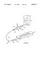
- FIG. 2is a pictorial view of an embodiment of a two-part article of the present invention, also for providing low voltage power from a car's electrical system through the cigarette lighter socket to an electronic device, illustrated by a cellular telephone.
- FIG. 3illustrates pictorially two embodiments of shapes of connectors which are required respectively by various embodiments of electronic devices within a plurality of such devices available in the marketplace, these shape embodiments being in addition to the shape of the connector shown in FIGS. 1 and 2.
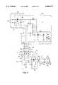
- FIG. 4is a circuit diagram illustrating in outline a typical embodiment of the article of the present invention and typical circuitry of such an article.
- FIG. 4is a pictorial view of a portion of FIG. 2, illustrating the substitution of an AC 110-volt convertor for a DC connector, with the converter being attached to a house or office electrical wiring system be being plugged into a wall socket.
- FIG. 6is a pictorial view of another embodiment of a two-part article of the present invention, also for providing low voltage power from a car's electrical system through the cigarette lighter socket to an electronic device, illustrated by a cellular telephone.
- FIGS. 2-5from which the invention may be compared with the prior art systems exemplified by the illustration in FIG. 1.
- the connector/conductor article of this inventionis generally designated 20 and is configured with two interacting but separable modules, a "universal” module 22 and a “device” module 24.
- the universal module 22has a physical structure and electrical circuitry which will connect to and operate with various standard power sources which are found in large numbers in the field. Most particularly, automobile cigarette lighter sockets, and in more recent vehicles, equivalent electrical take-off sockets (the cigarette lighter now often no longer being standard equipment on vehicles) are all of a single size and shape and almost all vehicles operate on a 12-volt DC electrical system. Consequently one universal module 22 has a line plug 26 which is shaped, wired and has contacts adapted to fit into and make electrical contact with corresponding contacts within socket 14 to allow the module 22 to draw electrical current and power from the vehicle's electrical system (not shown).
- Line plug 26is connected by a 2- or 3-wire conductor 28 to universal module connector (plug or socket) 30.
- Intermediate line plug 26 and module connector 30is common circuit 32 (designated as inside housing 34).
- Common circuit 32is not the equivalent of resistance circuit 10 of the prior art. Rather it contains only those electrical components of the article 20 which are required for all of the different devices 2 with which the several embodiments of the article 20 is intended to be used. It contains none of the electrical components which are specific to each specific type, model, or brand of such devices 2.
- common circuit 32may be disposed inside housing 36 which is integrated with universal module connector 30.
- common circuit 32may be divided between housings 34 and 36, but that is unduly complex and is not preferred.
- module 22A major alternative embodiment of module 22 is illustrated in FIG. 5.
- the article 20is a converter and operates from a 110-volt source such as a house or office electrical system (not shown).
- the conversion circuit 38is indicated as within housing 40 and connects with prongs 42 which plug into slots 44 in wall socket 46, which in turn is part of the house or office electrical system.
- the conversion circuitincludes a transformer to step down the 110 V house or office current to the same standard output voltage that is output by common circuit 32 and also includes a converter to changes the alternating house or office current to direct current.
- the common voltage DCis then output through conductor 28 to module plug 30 as described above.
- some or all of the conversion circuit 38can be housed in housing 36, but neither is preferred, since putting all of circuit 38 in housing 36 requires transmission of 110 V power through line 28, and putting some of it in housing 36 makes the system unduly complex.
- Module 22is thus a product which can be manufactured, inventoried, stocked and sold in quantity. It is not dependent upon specific models, brands or types of electronic devices 2, and therefore is not subject to obsolescence, recall, or return when a particular device 2 no longer is an active market product, either generally or in particular local areas. Consequently, customers can purchase a single module 22, and be assured that it will operate effectively with a number of different devices 2 which they may own.
- Module 22cannot operate alone, however, and requires one or more embodiments of module 24 to make the system workable for any device 2. It will be helpful to clarify the relationship between modules 22 and 24.
- the complete battery charger/power cable article 20 of this inventionmust of course include all of the components (such as resistors, capacitors, diodes, etc.) required for an operating charging/power circuit. Most of those components will be required in the circuit no matter what class (i.e., grouping of equivalent models, types or brands) of telephone, radio or other device 2 the cable article 20 is to be used with. These "universal" components are the ones which are present in module 22.
- circuit 50which is specific to the individual class of devices 2 which a particular article 20 is to be used with. It is these components, incorporated into circuit 50, which are housed in module 24.
- the uniqueness of the class of devices 2 of interestis due to a manufacturer's use of proprietary circuitry in its devices 2, including (but not limited to) a unique socket 4 shape which dictates a corresponding unique plug 6 shape, and a unique operating voltage, which dictates that module 24 contain one or more "device-specific" components [e.g., resistor(s) or capacitor(s)] needed to reduce the voltage output of the universal portion of the charging/power circuit (i.e., that portion in module 22) to the device's voltage.
- device-specific componentse.g., resistor(s) or capacitor(s)
- Housing 52also includes device module connector 54, which mates with universal module connector 30 to form an operable electrical connection between modules 22 and 24.
- universal module connector 30is shown as a male plug which is received within a female socket configuration of device module connector 54. It will be understood of course that these two configurations can be reversed, with connector 54 being the male plug and connector 30 being the female socket.
- Plug 6is, as discussed above, shaped to mate with socket 4 on device 2, regardless of the proprietary or unique shape of socket 4.
- the present inventionis not limited to one or a few plug configurations, but is compatible with any plug 6 configuration. (For that reason the plugs illustrated in FIGS. 2, 3 and 6 will be understood to be only examples and not indicative of any limitation.)
- the uniqueness or proprietary aspect of socket 4may reside in its well depth; well wall shape; cross-sectional shape; presence or absence of keyways or guide ribs; location, number and/or shape of electrical contacts within the well, or in combinations of these or other structures.
- plug 6will be configured to conform to those structures; for instance, a configuration of plug 6 different from that illustrated in FIG. 2, conforming to a different configuration of socket 4, is illustrated in FIG. 3 and designated 6'.
- Plug 6may also include non-electrical elements which allow it to releaseably lock into socket 4.
- the locking elementsmay cooperate with a corresponding structure within socket 4, on an adjacent surface of device 2, or a combination of both.
- the male/female structures of plug 6 and socket 4can be reversed, and such reverse mode is intended to be covered by this invention.
- Such a reverse configurationis exemplified in FIG. 3 by the socket designated 6", which would mate with a plug-form configuration of socket 4 (not shown).
- module 22 lengthsmight include, for instance, a series of lengths at 6" (15 cm) intervals over a range of 2'-5' (60-150 cm) total length, to produce overall article 20 lengths ranging between 21/2' and 6' (75-180 cm). Of course lengths of either or both modules 22 and 24 and of the complete article 20 may also be longer or shorter as desired.
- FIG. 6A different embodiment of the battery charger/power cable article of the present invention is illustrated in FIG. 6.
- all of the universal components and the connector for the vehicle socketare combined in a single housing unit which includes a JP11 socket 131.
- the universal modulehere designated 122, therefore has no external wires or cables itself; the connection between the contacts of connector 126 and universal circuit 132 is internal to housing 134.
- the socket 131is conventional and receives a corresponding conventional JP11 plug 151, to which is connected one end of connector 156, which may be considered the analog to connector 56 of the FIG. 2 embodiment.
- Connector 156 at its other endis connected to plug/housing 106, the interior of which contains the device-specific circuit 150, the equivalent of circuit 50 of the FIG.
- Plug/housing 106in turn plugs into socket 4 in device 2 in the manner described above.
- Thisis a particularly economical embodiment of the present article invention to manufacture, since the module 122 and its connector 126 are integrated into a single combination housing 134 and the module 124 concentrates the device-specific component(s) of circuit 150 into a unitary housing combination with plug 106. so that effectively the housing 52 and plug 6 of the FIG. 2 embodiment are integrated into a single unit in the FIG. 6 embodiment.
- the remainder of module 124comprises conductor 156 and JP11 plug 151, both of which are conventional products.
- a customer who owns a single universal module 22 productdoes not need to buy additional module 22 products each time he or she obtains or wants to use a different device 2--all that is needed is to obtain the appropriate device-specific module 24 product.
- the customersaves money and does not have to keep track of a variety of mutually incompatible long connector or converter products.
- the customercan add one or more short device specific modules 24, which when not in use can easily be stored in, for instance, a glove compartment of a car.
- the manufacturer, distributor and retaileralso benefit.
- the manufacturing operationsare simplified, since most of the article 20--the universal module 24--is manufactured in a single universal electrical and physical configuration, with only the chosen lengths of the conductor 28 being changed.
- the manufacture of the device specific modules 24is also simplified, since each module 24 is small and contains a minimal amount of circuitry. Additionally for the manufacturer, when a particular device 2 is withdrawn from the market only the unsold modules 24 for that specific device will be returned, so that the associated universal modules 22 are not affected and are not wasted by having to be returned and discarded as did the prior art unitary devices.
- the distributor and retailerbenefit by being able to stock and display a much wider assortment of articles 20. Since the modules 24 do not take up as much display space as do the modules 22, and of course much less overall than did the unitary prior art products, a limited portion of the display space can be assigned to an appropriate quantity of the different lengths of modules 22, and the remained used to display a wider variety of the smaller modules 24. This greatly improves the chances that the specific type of module 24 needed by a customer will be available, leading to greater sales and more customer satisfaction.
- FIG. 4An example of a circuit diagram for a typical article 20 of this invention as illustrated in FIG. 2 is shown in FIG. 4, which illustrates using a 12 V car electrical system to power or charge batteries of a cellular telephone.
- FIG. 2illustrates using a 12 V car electrical system to power or charge batteries of a cellular telephone.
- Each of the elements of the articleis indicated in FIG. 2, some by dotted outlines.
- contacts 58 to the vehicle's electrical systemare shown as mating with corresponding contacts 60 of plug 26, as are similar contact pair 62 of plug 30 and 64 of socket 54 and contact pair 68 of plug 6 and 66 of socket 4.
- Plug 26is integrated with module housing 34.
- the various electrical componentsare designed have the following values or identifications:
- the components which are in plug 26 or universal circuit 32are common to all of the devices 2 which the article 20 is intended to work with. It is those components (which in this example are C5, D4, R1 and R2) which are within module 24 and are specific to the example telephone device 2 of interest.
- the module 22shown separated from module 24 by indicator line 70
- the article 20thus presents a unique two-part structure which disposes "universal” and “device specific” electrical or electronic components into the separate parts of the article, providing versatility for the use, lower cost, improved manufacturing, and greater availability of different embodiments in the marketplace.
Landscapes
- Engineering & Computer Science (AREA)
- Power Engineering (AREA)
- Charge And Discharge Circuits For Batteries Or The Like (AREA)
Abstract
Description
______________________________________ C2 220 μF @ 16V C3 100 μF @ 3.5 V C4 470 μF C5 0.1 μF D1 IN4004 D2 IN5819 D3 Red LED D4 IN4004 J1 12-30 V DC IFP (2-wire) [Input] J2 (1, 2) Phone jack (3-wire) J3 Plug 6 [Output at desired voltage]JP2 Jumper R1 24 KΩ (1%) R2 12.7 KΩ (1%) R3 0.22 KΩ R4 1.2 KΩ U1 MC34063A ______________________________________
Claims (11)
Priority Applications (1)
| Application Number | Priority Date | Filing Date | Title |
|---|---|---|---|
| US09/225,984US6064177A (en) | 1999-01-05 | 1999-01-05 | Two-part battery charger/power cable article with multiple device capability |
Applications Claiming Priority (1)
| Application Number | Priority Date | Filing Date | Title |
|---|---|---|---|
| US09/225,984US6064177A (en) | 1999-01-05 | 1999-01-05 | Two-part battery charger/power cable article with multiple device capability |
Publications (1)
| Publication Number | Publication Date |
|---|---|
| US6064177Atrue US6064177A (en) | 2000-05-16 |
Family
ID=22847076
Family Applications (1)
| Application Number | Title | Priority Date | Filing Date |
|---|---|---|---|
| US09/225,984Expired - LifetimeUS6064177A (en) | 1999-01-05 | 1999-01-05 | Two-part battery charger/power cable article with multiple device capability |
Country Status (1)
| Country | Link |
|---|---|
| US (1) | US6064177A (en) |
Cited By (55)
| Publication number | Priority date | Publication date | Assignee | Title |
|---|---|---|---|---|
| USD463369S1 (en) | 2001-06-07 | 2002-09-24 | United Global Sourcing, Inc. | Flexible electric coupler |
| US20020171394A1 (en)* | 2000-07-03 | 2002-11-21 | Stephane Bohbot | Battery charger, in particular for a portable telephone |
| US6509659B1 (en)* | 2001-10-24 | 2003-01-21 | Motorola, Inc. | Cable or module identification apparatus and method |
| US6531657B1 (en) | 2002-01-31 | 2003-03-11 | Metra Electronics Corporation | Adapter wire harness for installing different autosound components into different vehicles |
| US20030117106A1 (en)* | 2001-12-21 | 2003-06-26 | Hwang Steve Han Shi | Charger with replaceable signal line for a car |
| US6650560B2 (en) | 2001-12-03 | 2003-11-18 | Mobility Electronics, Inc. | Dual input AC and DC power supply having a programmable DC output utilizing single-loop optical feedback |
| FR2841699A1 (en)* | 2002-07-01 | 2004-01-02 | France Telecom | CHARGER AND RECHARGE DEVICE |
| US6687516B2 (en)* | 1998-10-08 | 2004-02-03 | E-Lead Electronic Co., Ltd. | Hand-free receiver signal wire for mobile telephone |
| US6693413B1 (en) | 1994-04-26 | 2004-02-17 | Comarco Wireless Technologies, Inc. | Programmable power supply |
| US20040037102A1 (en)* | 2001-10-31 | 2004-02-26 | Mobility Electronics Inc. | Dual input AC/DC to programmable DC output converter |
| US6700808B2 (en) | 2002-02-08 | 2004-03-02 | Mobility Electronics, Inc. | Dual input AC and DC power supply having a programmable DC output utilizing a secondary buck converter |
| US20040085793A1 (en)* | 2001-12-03 | 2004-05-06 | Ejaz Afzal | Programmable power converter |
| US20040104705A1 (en)* | 2001-04-02 | 2004-06-03 | Frerking Melvin D. | Portable battery recharge station |
| US6747633B2 (en)* | 2001-02-23 | 2004-06-08 | Chic Technology Corp. | Wireless mouse recharge system |
| US6751109B2 (en) | 2001-10-31 | 2004-06-15 | Mobility Electronics, Inc. | Dual input AC/DC/ battery operated power supply |
| US6791853B2 (en) | 2001-12-03 | 2004-09-14 | Mobility Electronics, Inc. | Dual input AC/DC power converter having a programmable peripheral power hub module |
| US6831848B2 (en) | 1994-04-26 | 2004-12-14 | Comarco Wireless Technologies, Inc. | Programmable power supply to simultaneously power a plurality of electronic devices |
| US20040251873A1 (en)* | 2003-03-24 | 2004-12-16 | Simoes Felipe O. | Battery charging assembly |
| US6836101B2 (en) | 2002-12-05 | 2004-12-28 | Comarco Wireless Technologies, Inc. | Tip having active circuitry |
| US20050001485A1 (en)* | 2003-07-03 | 2005-01-06 | Opher Pail | Electronic device display system and method |
| US20050127757A1 (en)* | 2003-12-15 | 2005-06-16 | Wayne Wilson | Power supply, and associated method, exhibiting selectable electrical characteristics |
| US20050189914A1 (en)* | 2003-12-05 | 2005-09-01 | Sam Esses | Universal cellular telephone battery charger |
| US20050266730A1 (en)* | 1994-04-26 | 2005-12-01 | Comarco Wireless Technologies, Inc. | Programmable power supply |
| US20050270812A1 (en)* | 2004-02-24 | 2005-12-08 | Patrizio Vinciarelli | Universal AC adapter |
| US6980204B1 (en)* | 2000-09-21 | 2005-12-27 | Jeffrey Charles Hawkins | Charging and communication cable system for a mobile computer apparatus |
| US6994592B1 (en) | 2004-08-27 | 2006-02-07 | Hop-On Wireless, Inc. | Universal charging apparatus |
| WO2006018103A1 (en)* | 2004-08-18 | 2006-02-23 | Jacques Giribet Guadamillas | Electrical charging or supply device |
| US20060071558A1 (en)* | 2004-09-30 | 2006-04-06 | Targus Group International, Inc. | Programmable power adaptor |
| WO2006066864A1 (en)* | 2004-12-21 | 2006-06-29 | Bury Sp.Z.O.O. | Holding device for receiving a mobile telephone provided with a specific cable comprising a device for controlling the charging |
| US20060226712A1 (en)* | 2005-04-06 | 2006-10-12 | Flexsil, Inc. | Universal DC power |
| US20060256594A1 (en)* | 2005-05-11 | 2006-11-16 | Lam Man L | Apparatus, and associated method, for converting electrical power into form for powering a load device |
| US20070030715A1 (en)* | 2005-08-03 | 2007-02-08 | Mihai-Costin Manolescu | Power supply that reads power requirement information across a DC power cord from a load |
| US20070029879A1 (en)* | 2005-08-04 | 2007-02-08 | Eldredge James G | Distribution of universal DC power in buildings |
| US20070195558A1 (en)* | 2004-06-19 | 2007-08-23 | Smart Power Solutions Inc. | Power supply for both ac and dc |
| JP2007280921A (en)* | 2006-04-11 | 2007-10-25 | Modern Sense Ltd | Universal charger and/or power adaptor |
| US20070263703A1 (en)* | 2006-04-28 | 2007-11-15 | Robert Mahaffey | Power supply system |
| US20080059816A1 (en)* | 2006-08-30 | 2008-03-06 | Frank Patrick Paniagua | Power supply capable of receiving digital communications from electronic devices |
| FR2908938A1 (en)* | 2006-11-22 | 2008-05-23 | Peugeot Citroen Automobiles Sa | Power supply system for e.g. mobile phone, has resistor integrated to power cords or mobile device and connected to output and adjustment terminals, when mobile device is connected to removable stubs by power cords |
| US20080211310A1 (en)* | 2006-12-06 | 2008-09-04 | Det International Holding Limited | Portable power supply apparatus capable of receiving ac or dc input power |
| US20080303483A1 (en)* | 2004-06-10 | 2008-12-11 | Sendyne Corporation | External Versatile Battery with Power Saving Mode |
| US20090095106A1 (en)* | 2007-10-12 | 2009-04-16 | Metropolitan Air Technolog | Motorized gear and coupling system |
| US20100052577A1 (en)* | 2008-09-03 | 2010-03-04 | Michael Scott Brownlee | Power supply system for a building |
| US20100164291A1 (en)* | 2008-12-26 | 2010-07-01 | Pichkur Yaroslav A | System, socket and plug apparatus for DC power distribution and usage |
| USRE41675E1 (en)* | 2001-09-07 | 2010-09-14 | Sen-Hsiang Liu | Power charging system and related apparatus |
| US20100254162A1 (en)* | 2009-04-01 | 2010-10-07 | Comarco Wireless Technologies, Inc. | Modular power adapter |
| USD634058S1 (en)* | 2008-08-05 | 2011-03-08 | Lunera Lighting, Inc. | Electric door for LED panel fixture |
| US20110095605A1 (en)* | 2009-10-28 | 2011-04-28 | Comarco Wireless Technologies, Inc. | Power supply equipment to simultaneously power multiple electronic device |
| EP1936790A3 (en)* | 2006-12-12 | 2012-01-11 | DET International Holding Limited | Portable power supply with ac and dc input |
| US8319373B2 (en) | 2008-12-26 | 2012-11-27 | Pichkur Yaroslav A | System, socket and plug apparatus for DC power distribution and usage |
| US8550827B1 (en) | 2012-07-25 | 2013-10-08 | Targus Group International, Inc. | Multi-sleeve power tips |
| US8677286B2 (en) | 2003-05-01 | 2014-03-18 | Hewlett-Packard Development Company, L.P. | Dynamic sizing user interface method and system for data display |
| US8821199B2 (en) | 2012-07-25 | 2014-09-02 | Targus Group International, Inc. | Multi-prong power tip adaptor |
| US20150115897A1 (en)* | 2013-10-24 | 2015-04-30 | Etron Technology, Inc. | Universal power delivery cable, power delivery controller applied to a universal serial bus cable, and universal serial bus cable |
| US10063958B2 (en) | 2014-11-07 | 2018-08-28 | Microsoft Technology Licensing, Llc | Earpiece attachment devices |
| US10855087B1 (en) | 2004-01-15 | 2020-12-01 | Comarco Wireless Systems Llc | Power supply systems |
Citations (10)
| Publication number | Priority date | Publication date | Assignee | Title |
|---|---|---|---|---|
| US4829224A (en)* | 1988-05-23 | 1989-05-09 | George Gandelman | Battery pack for cellular telephone |
| US5007863A (en)* | 1990-09-17 | 1991-04-16 | Jialuo Xuan | Module-type multi-function electrical power adapter for automobiles and the like |
| US5127844A (en)* | 1990-04-12 | 1992-07-07 | Nokia Mobile Phones Ltd. | Connection block for plug-in adapter |
| US5170067A (en)* | 1990-11-27 | 1992-12-08 | Unitech Industries, Inc. | Plug insertable into a vehicle cigarette lighter receptacle and having electronic components and a printed circuit board therein |
| US5326283A (en)* | 1993-08-03 | 1994-07-05 | E Lead Electronic Co., Ltd. | Electrical plug for automobile use |
| US5510691A (en)* | 1994-04-13 | 1996-04-23 | Xtend Micro Products, Inc | Modular power supply and modular interconnect system for portable electronic equipment |
| US5648712A (en)* | 1995-08-29 | 1997-07-15 | Asian Micro Sources, Inc. | Universally interchangeable and modular power supply with integrated battery charger |
| US5714805A (en)* | 1996-02-28 | 1998-02-03 | Brian J. Lobaugh | Vehicle accessory power take-off system including phono/RCA type plug and jack for use with cigarette lighter plug/jack |
| US5733674A (en)* | 1997-02-12 | 1998-03-31 | Law; Steven | Power supply systems for portable electronic devices |
| US5847541A (en)* | 1995-08-29 | 1998-12-08 | Advanced Mobile Solutions, Inc. | Universally interchangeable and modular power supply with integrated battery charger |
- 1999
- 1999-01-05USUS09/225,984patent/US6064177A/ennot_activeExpired - Lifetime
Patent Citations (10)
| Publication number | Priority date | Publication date | Assignee | Title |
|---|---|---|---|---|
| US4829224A (en)* | 1988-05-23 | 1989-05-09 | George Gandelman | Battery pack for cellular telephone |
| US5127844A (en)* | 1990-04-12 | 1992-07-07 | Nokia Mobile Phones Ltd. | Connection block for plug-in adapter |
| US5007863A (en)* | 1990-09-17 | 1991-04-16 | Jialuo Xuan | Module-type multi-function electrical power adapter for automobiles and the like |
| US5170067A (en)* | 1990-11-27 | 1992-12-08 | Unitech Industries, Inc. | Plug insertable into a vehicle cigarette lighter receptacle and having electronic components and a printed circuit board therein |
| US5326283A (en)* | 1993-08-03 | 1994-07-05 | E Lead Electronic Co., Ltd. | Electrical plug for automobile use |
| US5510691A (en)* | 1994-04-13 | 1996-04-23 | Xtend Micro Products, Inc | Modular power supply and modular interconnect system for portable electronic equipment |
| US5648712A (en)* | 1995-08-29 | 1997-07-15 | Asian Micro Sources, Inc. | Universally interchangeable and modular power supply with integrated battery charger |
| US5847541A (en)* | 1995-08-29 | 1998-12-08 | Advanced Mobile Solutions, Inc. | Universally interchangeable and modular power supply with integrated battery charger |
| US5714805A (en)* | 1996-02-28 | 1998-02-03 | Brian J. Lobaugh | Vehicle accessory power take-off system including phono/RCA type plug and jack for use with cigarette lighter plug/jack |
| US5733674A (en)* | 1997-02-12 | 1998-03-31 | Law; Steven | Power supply systems for portable electronic devices |
Cited By (127)
| Publication number | Priority date | Publication date | Assignee | Title |
|---|---|---|---|---|
| US7450390B2 (en) | 1994-04-26 | 2008-11-11 | Comarco Wireless Technologies, Inc. | Programmable power supply |
| US20050266730A1 (en)* | 1994-04-26 | 2005-12-01 | Comarco Wireless Technologies, Inc. | Programmable power supply |
| US20100109436A1 (en)* | 1994-04-26 | 2010-05-06 | Comarco Wireless Technologies, Inc. | Power supply equipment for simultaneously providing operating voltages to a plurality of devices |
| US7863770B2 (en) | 1994-04-26 | 2011-01-04 | Comarco Wireless Technologies, Inc. | Power supply equipment for simultaneously providing operating voltages to a plurality of devices |
| US7649279B2 (en) | 1994-04-26 | 2010-01-19 | Comarco Wireless Technologies, Inc | Power supply for simultaneously providing operating voltages to a plurality of devices |
| US7613021B2 (en) | 1994-04-26 | 2009-11-03 | Comarco Wireless Technologies, Inc | Small form factor power supply |
| US7495941B2 (en) | 1994-04-26 | 2009-02-24 | Comarco Wireless Technologies, Inc. | Power supply equipment with matching indicators on converter and connector adapters |
| US6922347B2 (en) | 1994-04-26 | 2005-07-26 | Comarco Wireless Technologies, Inc. | Programmable power supply |
| US6693413B1 (en) | 1994-04-26 | 2004-02-17 | Comarco Wireless Technologies, Inc. | Programmable power supply |
| US7460381B2 (en) | 1994-04-26 | 2008-12-02 | Comarco Wireless Technologies, Inc. | Programmable power supply |
| US7450403B2 (en) | 1994-04-26 | 2008-11-11 | Comarco Wireless Technologies, Inc. | Switching power supply utilizing switch-selectable resistors to determine output voltage |
| US20060215381A1 (en)* | 1994-04-26 | 2006-09-28 | Comarco Wireless Technologies, Inc. | Programmable power supply |
| US20050024907A1 (en)* | 1994-04-26 | 2005-02-03 | Comarco Wireless Technologies, Inc. | Programmable power supply |
| US20080151581A1 (en)* | 1994-04-26 | 2008-06-26 | Comarco Wireless Technologies, Inc. | Small form factor power supply |
| US6707284B2 (en) | 1994-04-26 | 2004-03-16 | Comarco Wireless Technologies, Inc. | Programmable power supply |
| US20070279952A1 (en)* | 1994-04-26 | 2007-12-06 | Comarco Wireless Technologies, Inc. | Switching power supply utilizing switch-selectable resistors to determine output voltage |
| US7266003B2 (en) | 1994-04-26 | 2007-09-04 | Comarco Wireless Technologies, Inc. | Programmable power supply |
| US7145787B2 (en) | 1994-04-26 | 2006-12-05 | Comarco Wireless Technologies, Inc. | Programmable power supply |
| US20060256595A1 (en)* | 1994-04-26 | 2006-11-16 | Comarco Wireless Technologies, Inc. | Power supply for simultaneously providing operating voltages to a plurality of devices |
| US6809943B2 (en) | 1994-04-26 | 2004-10-26 | Comarco Wireless Technologies, Inc. | Programmable power supply |
| US6831848B2 (en) | 1994-04-26 | 2004-12-14 | Comarco Wireless Technologies, Inc. | Programmable power supply to simultaneously power a plurality of electronic devices |
| US20060227580A1 (en)* | 1994-04-26 | 2006-10-12 | Comarco Wireless Technologies Inc. | Programmable power supply |
| US6687516B2 (en)* | 1998-10-08 | 2004-02-03 | E-Lead Electronic Co., Ltd. | Hand-free receiver signal wire for mobile telephone |
| US20020171394A1 (en)* | 2000-07-03 | 2002-11-21 | Stephane Bohbot | Battery charger, in particular for a portable telephone |
| US20060103642A1 (en)* | 2000-09-21 | 2006-05-18 | Hawkins Jeffrey C | Charging and communication cable system for a mobile computer apparatus |
| US6980204B1 (en)* | 2000-09-21 | 2005-12-27 | Jeffrey Charles Hawkins | Charging and communication cable system for a mobile computer apparatus |
| US6747633B2 (en)* | 2001-02-23 | 2004-06-08 | Chic Technology Corp. | Wireless mouse recharge system |
| US7405535B2 (en) | 2001-04-02 | 2008-07-29 | At&T Delaware Intellectual Property, Inc. | Portable battery recharge station |
| US20040104705A1 (en)* | 2001-04-02 | 2004-06-03 | Frerking Melvin D. | Portable battery recharge station |
| USD463369S1 (en) | 2001-06-07 | 2002-09-24 | United Global Sourcing, Inc. | Flexible electric coupler |
| USRE41675E1 (en)* | 2001-09-07 | 2010-09-14 | Sen-Hsiang Liu | Power charging system and related apparatus |
| US6509659B1 (en)* | 2001-10-24 | 2003-01-21 | Motorola, Inc. | Cable or module identification apparatus and method |
| US20060007715A1 (en)* | 2001-10-31 | 2006-01-12 | Mobility Electronics Inc. | AC/DC power converter |
| US7646620B2 (en) | 2001-10-31 | 2010-01-12 | Igo, Inc. | AC/DC power converter |
| US6775163B2 (en) | 2001-10-31 | 2004-08-10 | Mobility Electronics Inc. | Dual input AC/DC to programmable DC output converter |
| US6937490B2 (en) | 2001-10-31 | 2005-08-30 | Mobility Electronics, Inc. | Dual input AC and DC power supply having a programmable DC output utilizing a modular programmable feedback loop |
| US20040037102A1 (en)* | 2001-10-31 | 2004-02-26 | Mobility Electronics Inc. | Dual input AC/DC to programmable DC output converter |
| US20040170039A1 (en)* | 2001-10-31 | 2004-09-02 | Mobility Electronics Inc. | Dual input AC and DC power supply having a programmable DC output utilizing a secondary buck converter |
| US6751109B2 (en) | 2001-10-31 | 2004-06-15 | Mobility Electronics, Inc. | Dual input AC/DC/ battery operated power supply |
| US6791853B2 (en) | 2001-12-03 | 2004-09-14 | Mobility Electronics, Inc. | Dual input AC/DC power converter having a programmable peripheral power hub module |
| US6650560B2 (en) | 2001-12-03 | 2003-11-18 | Mobility Electronics, Inc. | Dual input AC and DC power supply having a programmable DC output utilizing single-loop optical feedback |
| US20040085793A1 (en)* | 2001-12-03 | 2004-05-06 | Ejaz Afzal | Programmable power converter |
| US6903950B2 (en) | 2001-12-03 | 2005-06-07 | Mobility Electronics, Inc. | Programmable power converter |
| US7012403B2 (en)* | 2001-12-21 | 2006-03-14 | Steve Han Shi Hwang | Charger with replaceable signal line for a car |
| US20030117106A1 (en)* | 2001-12-21 | 2003-06-26 | Hwang Steve Han Shi | Charger with replaceable signal line for a car |
| US6531657B1 (en) | 2002-01-31 | 2003-03-11 | Metra Electronics Corporation | Adapter wire harness for installing different autosound components into different vehicles |
| US6700808B2 (en) | 2002-02-08 | 2004-03-02 | Mobility Electronics, Inc. | Dual input AC and DC power supply having a programmable DC output utilizing a secondary buck converter |
| FR2841699A1 (en)* | 2002-07-01 | 2004-01-02 | France Telecom | CHARGER AND RECHARGE DEVICE |
| US20070182388A1 (en)* | 2002-12-05 | 2007-08-09 | Comarco Wireless Technologies, Inc. | Tip having active circuitry |
| US6836101B2 (en) | 2002-12-05 | 2004-12-28 | Comarco Wireless Technologies, Inc. | Tip having active circuitry |
| US20050024030A1 (en)* | 2002-12-05 | 2005-02-03 | Lanni Thomas W. | Tip having active circuitry |
| US7193398B2 (en) | 2002-12-05 | 2007-03-20 | Comarco Wireless Technologies, Inc | Tip having active circuitry |
| US7365524B2 (en) | 2002-12-05 | 2008-04-29 | Comarco Wireless Technologies, Inc. | Tip having active circuitry |
| EP1462904A3 (en)* | 2002-12-05 | 2005-08-03 | Comarco Wireless Technologies, Inc. | Tip for a power supply having active circuitry |
| US20040251873A1 (en)* | 2003-03-24 | 2004-12-16 | Simoes Felipe O. | Battery charging assembly |
| US20090137156A1 (en)* | 2003-03-24 | 2009-05-28 | Simoes Felipe O | Battery charging assembly |
| US8280455B2 (en) | 2003-03-24 | 2012-10-02 | Research In Motion Limited | Battery charging assembly |
| US7489952B2 (en)* | 2003-03-24 | 2009-02-10 | Research In Motion Limited | Battery charging assembly |
| US20100270971A1 (en)* | 2003-03-24 | 2010-10-28 | Research In Motion Limited | Battery charging assembly |
| US7769413B2 (en) | 2003-03-24 | 2010-08-03 | Research In Motion Limited | Battery charging assembly |
| US8677286B2 (en) | 2003-05-01 | 2014-03-18 | Hewlett-Packard Development Company, L.P. | Dynamic sizing user interface method and system for data display |
| US20060113842A1 (en)* | 2003-07-03 | 2006-06-01 | Opher Pail | Electronic device display system and method |
| WO2005008620A3 (en)* | 2003-07-03 | 2005-09-15 | Opher Pail | Electronic device display system and method |
| US20050001485A1 (en)* | 2003-07-03 | 2005-01-06 | Opher Pail | Electronic device display system and method |
| US7015596B2 (en)* | 2003-07-03 | 2006-03-21 | Opher Pail | Electronic device display system and method |
| US20050189914A1 (en)* | 2003-12-05 | 2005-09-01 | Sam Esses | Universal cellular telephone battery charger |
| US7166937B2 (en) | 2003-12-15 | 2007-01-23 | Radio Shack Corporation | Power supply, and associated method, exhibiting selectable electrical characteristics |
| US20050127757A1 (en)* | 2003-12-15 | 2005-06-16 | Wayne Wilson | Power supply, and associated method, exhibiting selectable electrical characteristics |
| US10951042B2 (en) | 2004-01-15 | 2021-03-16 | Comarco Wireless Systems Llc | Power supply systems |
| US10855086B2 (en) | 2004-01-15 | 2020-12-01 | Comarco Wireless Systems Llc | Power supply equipment utilizing interchangeable tips to provide power and a data signal to electronic devices |
| US10855087B1 (en) | 2004-01-15 | 2020-12-01 | Comarco Wireless Systems Llc | Power supply systems |
| US11586233B2 (en) | 2004-01-15 | 2023-02-21 | Comarco Wireless Systems Llc | Power supply systems |
| US9413259B1 (en) | 2004-02-24 | 2016-08-09 | Vlt, Inc. | Universal AC adaptor |
| US8462527B1 (en) | 2004-02-24 | 2013-06-11 | Vlt, Inc. | Universal AC adaptor |
| US7940540B2 (en) | 2004-02-24 | 2011-05-10 | Vlt, Inc. | Universal AC adaptor |
| US20050270812A1 (en)* | 2004-02-24 | 2005-12-08 | Patrizio Vinciarelli | Universal AC adapter |
| US7548441B2 (en) | 2004-02-24 | 2009-06-16 | Vlt, Inc. | Universal AC adapter |
| US20080303483A1 (en)* | 2004-06-10 | 2008-12-11 | Sendyne Corporation | External Versatile Battery with Power Saving Mode |
| US20070195558A1 (en)* | 2004-06-19 | 2007-08-23 | Smart Power Solutions Inc. | Power supply for both ac and dc |
| US7502233B2 (en) | 2004-06-19 | 2009-03-10 | Smart Power Solutions Inc. | DC power supply using either AC or DC input for both |
| WO2006018103A1 (en)* | 2004-08-18 | 2006-02-23 | Jacques Giribet Guadamillas | Electrical charging or supply device |
| US20060046576A1 (en)* | 2004-08-27 | 2006-03-02 | Hop-On Wireless, Inc. | Universal charging apparatus |
| US6994592B1 (en) | 2004-08-27 | 2006-02-07 | Hop-On Wireless, Inc. | Universal charging apparatus |
| US7646107B2 (en) | 2004-09-30 | 2010-01-12 | Targus Group Internatnional, Inc. | Programmable power adaptor |
| US20060071558A1 (en)* | 2004-09-30 | 2006-04-06 | Targus Group International, Inc. | Programmable power adaptor |
| US8099138B2 (en) | 2004-12-21 | 2012-01-17 | Bury Sp.Z.O.O. | Holding apparatus for accommodating a mobile telephone provided with a specific cable comprising a device for controlling charging |
| WO2006066864A1 (en)* | 2004-12-21 | 2006-06-29 | Bury Sp.Z.O.O. | Holding device for receiving a mobile telephone provided with a specific cable comprising a device for controlling the charging |
| US20090305748A1 (en)* | 2004-12-21 | 2009-12-10 | Roman Piekarz | Holding apparatus accommodating a mobile telephone provided with a specific cable comprising a device for controlling charging |
| GB2437000B (en)* | 2004-12-21 | 2008-06-25 | Bury Sp Zoo | A telephone system comprising a hands-free installation and a holding apparatus for accommodating a mobile telephone |
| GB2437000A (en)* | 2004-12-21 | 2007-10-10 | Bury Sp Zoo | Holding device for receiving a mobile telephone provided with a specific cable comprising a device for controlling the charging |
| US20060226712A1 (en)* | 2005-04-06 | 2006-10-12 | Flexsil, Inc. | Universal DC power |
| US7466042B2 (en) | 2005-04-06 | 2008-12-16 | Flexsil, Inc. | Universal DC power |
| US20070228831A1 (en)* | 2005-04-06 | 2007-10-04 | Flexsil, Inc. | Universal dc power |
| US20060256594A1 (en)* | 2005-05-11 | 2006-11-16 | Lam Man L | Apparatus, and associated method, for converting electrical power into form for powering a load device |
| US7298120B2 (en) | 2005-05-11 | 2007-11-20 | Radio Shack Corporation | Apparatus, and associated method, for converting electrical power into form for powering a load device |
| US7508687B2 (en) | 2005-08-03 | 2009-03-24 | Mihai-Costin Manolescu | Power supply that reads power requirement information across a DC power cord from a load |
| US20070030715A1 (en)* | 2005-08-03 | 2007-02-08 | Mihai-Costin Manolescu | Power supply that reads power requirement information across a DC power cord from a load |
| US20070029879A1 (en)* | 2005-08-04 | 2007-02-08 | Eldredge James G | Distribution of universal DC power in buildings |
| JP2007280921A (en)* | 2006-04-11 | 2007-10-25 | Modern Sense Ltd | Universal charger and/or power adaptor |
| US20070278996A1 (en)* | 2006-04-11 | 2007-12-06 | Modern Sense Limited | Universal battery charger and/or power adaptor |
| US7597570B2 (en) | 2006-04-11 | 2009-10-06 | Modern Sense Limited | Universal battery charger and/or power adaptor |
| US7642671B2 (en) | 2006-04-28 | 2010-01-05 | Acco Brands Usa Llc | Power supply system providing two output voltages |
| US20070263703A1 (en)* | 2006-04-28 | 2007-11-15 | Robert Mahaffey | Power supply system |
| US20100090531A1 (en)* | 2006-04-28 | 2010-04-15 | Robert Mahaffey | Power supply system |
| US8212386B2 (en) | 2006-04-28 | 2012-07-03 | ACCO Brands Corporation | Power supply system |
| US8370650B2 (en) | 2006-08-30 | 2013-02-05 | Greenplug, Inc. | Power supply capable of receiving digital communications from electronic devices |
| US20080059816A1 (en)* | 2006-08-30 | 2008-03-06 | Frank Patrick Paniagua | Power supply capable of receiving digital communications from electronic devices |
| US20090259867A1 (en)* | 2006-08-30 | 2009-10-15 | Paniagua Jr Frank | Power Supply Capable of Receiving Digital Communications from Electronic Devices |
| FR2908938A1 (en)* | 2006-11-22 | 2008-05-23 | Peugeot Citroen Automobiles Sa | Power supply system for e.g. mobile phone, has resistor integrated to power cords or mobile device and connected to output and adjustment terminals, when mobile device is connected to removable stubs by power cords |
| US20080211310A1 (en)* | 2006-12-06 | 2008-09-04 | Det International Holding Limited | Portable power supply apparatus capable of receiving ac or dc input power |
| EP1936790A3 (en)* | 2006-12-12 | 2012-01-11 | DET International Holding Limited | Portable power supply with ac and dc input |
| US20090095106A1 (en)* | 2007-10-12 | 2009-04-16 | Metropolitan Air Technolog | Motorized gear and coupling system |
| USD634058S1 (en)* | 2008-08-05 | 2011-03-08 | Lunera Lighting, Inc. | Electric door for LED panel fixture |
| US8441216B2 (en) | 2008-09-03 | 2013-05-14 | ALVA Systems, Inc. | Power supply system for a building |
| US20100052577A1 (en)* | 2008-09-03 | 2010-03-04 | Michael Scott Brownlee | Power supply system for a building |
| US8319373B2 (en) | 2008-12-26 | 2012-11-27 | Pichkur Yaroslav A | System, socket and plug apparatus for DC power distribution and usage |
| US20100164291A1 (en)* | 2008-12-26 | 2010-07-01 | Pichkur Yaroslav A | System, socket and plug apparatus for DC power distribution and usage |
| US8212406B2 (en) | 2008-12-26 | 2012-07-03 | Yaroslav A. Pichkur | System, socket and plug apparatus for DC power distribution and usage |
| US20100254162A1 (en)* | 2009-04-01 | 2010-10-07 | Comarco Wireless Technologies, Inc. | Modular power adapter |
| US8213204B2 (en) | 2009-04-01 | 2012-07-03 | Comarco Wireless Technologies, Inc. | Modular power adapter |
| US20110095605A1 (en)* | 2009-10-28 | 2011-04-28 | Comarco Wireless Technologies, Inc. | Power supply equipment to simultaneously power multiple electronic device |
| US8354760B2 (en) | 2009-10-28 | 2013-01-15 | Comarco Wireless Technologies, Inc. | Power supply equipment to simultaneously power multiple electronic device |
| US8550827B1 (en) | 2012-07-25 | 2013-10-08 | Targus Group International, Inc. | Multi-sleeve power tips |
| US8821199B2 (en) | 2012-07-25 | 2014-09-02 | Targus Group International, Inc. | Multi-prong power tip adaptor |
| US10044207B2 (en)* | 2013-10-24 | 2018-08-07 | Eever Technology, Inc. | Universal power delivery cable, power delivery controller applied to a universal serial bus cable, and universal serial bus cable |
| US20150115897A1 (en)* | 2013-10-24 | 2015-04-30 | Etron Technology, Inc. | Universal power delivery cable, power delivery controller applied to a universal serial bus cable, and universal serial bus cable |
| US10063958B2 (en) | 2014-11-07 | 2018-08-28 | Microsoft Technology Licensing, Llc | Earpiece attachment devices |
Similar Documents
| Publication | Publication Date | Title |
|---|---|---|
| US6064177A (en) | Two-part battery charger/power cable article with multiple device capability | |
| US7183743B2 (en) | Adapter system for recharging portable electronic devices and its associated method of use | |
| US5155860A (en) | Cellular portable telephone battery pack and programmer interface | |
| US5510691A (en) | Modular power supply and modular interconnect system for portable electronic equipment | |
| US5963014A (en) | Serially connected charger | |
| US20140235359A1 (en) | Video game controller charging system having a docking structure | |
| US20050248312A1 (en) | Portable power supply with computer port | |
| US20050070154A1 (en) | Universal computer cable kit with interchangeable quick connectors | |
| US20070216352A1 (en) | Cell phone charging stand | |
| US20070091656A1 (en) | Power adapter | |
| CN113826297A (en) | Modular device charging station | |
| US10367367B1 (en) | Electronic watch recharging device | |
| KR200484178Y1 (en) | Multi-Charging System | |
| US8274257B2 (en) | Portable charging equipment | |
| RU2263384C2 (en) | Universal intelligent mobile phone battery charger | |
| US20060049695A1 (en) | Portable power supply with computer ports | |
| US20010053635A1 (en) | Power connector ground polarization insert and connector used therewith | |
| CA3159957A1 (en) | Ladder with battery power, and methods | |
| US20070060210A1 (en) | Strap attached with a cell unit | |
| EP1603008A1 (en) | Portable power supply with computer port | |
| KR200273736Y1 (en) | a plugger for articles filling | |
| US7629767B2 (en) | Mobile communication terminal having USB interface unit therein | |
| KR200203679Y1 (en) | Detachable Charger for Wireless Terminal | |
| CN219833847U (en) | Data video entertainment integrated module | |
| CN2838050Y (en) | Portable power supply system |
Legal Events
| Date | Code | Title | Description |
|---|---|---|---|
| STCF | Information on status: patent grant | Free format text:PATENTED CASE | |
| AS | Assignment | Owner name:GEIER, WILLIAM F., VIRGINIA Free format text:ASSET PURCHASE AGREEMENT;ASSIGNOR:DIXON, STEVE C.;REEL/FRAME:013691/0978 Effective date:20021211 | |
| AS | Assignment | Owner name:MOBILITY ELECTRONICS, INC., ARIZONA Free format text:ASSIGNMENT OF ASSIGNORS INTEREST;ASSIGNORS:DIXON, STEVE C.;GEIER, WILLIAM F.;REEL/FRAME:014321/0512 Effective date:20030724 | |
| REMI | Maintenance fee reminder mailed | ||
| FPAY | Fee payment | Year of fee payment:4 | |
| SULP | Surcharge for late payment | ||
| FPAY | Fee payment | Year of fee payment:8 | |
| AS | Assignment | Owner name:IGO, INC., ARIZONA Free format text:CHANGE OF NAME;ASSIGNOR:MOBILITY ELECTRONICS, INC.;REEL/FRAME:021076/0664 Effective date:20080521 Owner name:IGO, INC.,ARIZONA Free format text:CHANGE OF NAME;ASSIGNOR:MOBILITY ELECTRONICS, INC.;REEL/FRAME:021076/0664 Effective date:20080521 | |
| FPAY | Fee payment | Year of fee payment:12 | |
| AS | Assignment | Owner name:PNC BANK, NATIONAL ASSOCIATION, PENNSYLVANIA Free format text:SECURITY INTEREST;ASSIGNOR:IGO, INC.;REEL/FRAME:048992/0044 Effective date:20181231 |