US6063339A - Method and apparatus for high-speed dot array dispensing - Google Patents
Method and apparatus for high-speed dot array dispensingDownload PDFInfo
- Publication number
- US6063339A US6063339AUS09/146,614US14661498AUS6063339AUS 6063339 AUS6063339 AUS 6063339AUS 14661498 AUS14661498 AUS 14661498AUS 6063339 AUS6063339 AUS 6063339A
- Authority
- US
- United States
- Prior art keywords
- dispensing
- reagent
- substrate
- dispensing head
- signal
- Prior art date
- Legal status (The legal status is an assumption and is not a legal conclusion. Google has not performed a legal analysis and makes no representation as to the accuracy of the status listed.)
- Expired - Lifetime
Links
Images


Classifications
- B—PERFORMING OPERATIONS; TRANSPORTING
- B01—PHYSICAL OR CHEMICAL PROCESSES OR APPARATUS IN GENERAL
- B01L—CHEMICAL OR PHYSICAL LABORATORY APPARATUS FOR GENERAL USE
- B01L3/00—Containers or dishes for laboratory use, e.g. laboratory glassware; Droppers
- B01L3/02—Burettes; Pipettes
- B01L3/0241—Drop counters; Drop formers
- B01L3/0265—Drop counters; Drop formers using valves to interrupt or meter fluid flow, e.g. using solenoids or metering valves
- B—PERFORMING OPERATIONS; TRANSPORTING
- B01—PHYSICAL OR CHEMICAL PROCESSES OR APPARATUS IN GENERAL
- B01J—CHEMICAL OR PHYSICAL PROCESSES, e.g. CATALYSIS OR COLLOID CHEMISTRY; THEIR RELEVANT APPARATUS
- B01J19/00—Chemical, physical or physico-chemical processes in general; Their relevant apparatus
- B01J19/0046—Sequential or parallel reactions, e.g. for the synthesis of polypeptides or polynucleotides; Apparatus and devices for combinatorial chemistry or for making molecular arrays
- B—PERFORMING OPERATIONS; TRANSPORTING
- B05—SPRAYING OR ATOMISING IN GENERAL; APPLYING FLUENT MATERIALS TO SURFACES, IN GENERAL
- B05B—SPRAYING APPARATUS; ATOMISING APPARATUS; NOZZLES
- B05B1/00—Nozzles, spray heads or other outlets, with or without auxiliary devices such as valves, heating means
- B05B1/30—Nozzles, spray heads or other outlets, with or without auxiliary devices such as valves, heating means designed to control volume of flow, e.g. with adjustable passages
- B05B1/3033—Nozzles, spray heads or other outlets, with or without auxiliary devices such as valves, heating means designed to control volume of flow, e.g. with adjustable passages the control being effected by relative coaxial longitudinal movement of the controlling element and the spray head
- B05B1/304—Nozzles, spray heads or other outlets, with or without auxiliary devices such as valves, heating means designed to control volume of flow, e.g. with adjustable passages the control being effected by relative coaxial longitudinal movement of the controlling element and the spray head the controlling element being a lift valve
- B05B1/3046—Nozzles, spray heads or other outlets, with or without auxiliary devices such as valves, heating means designed to control volume of flow, e.g. with adjustable passages the control being effected by relative coaxial longitudinal movement of the controlling element and the spray head the controlling element being a lift valve the valve element, e.g. a needle, co-operating with a valve seat located downstream of the valve element and its actuating means, generally in the proximity of the outlet orifice
- B05B1/3053—Nozzles, spray heads or other outlets, with or without auxiliary devices such as valves, heating means designed to control volume of flow, e.g. with adjustable passages the control being effected by relative coaxial longitudinal movement of the controlling element and the spray head the controlling element being a lift valve the valve element, e.g. a needle, co-operating with a valve seat located downstream of the valve element and its actuating means, generally in the proximity of the outlet orifice the actuating means being a solenoid
- B—PERFORMING OPERATIONS; TRANSPORTING
- B05—SPRAYING OR ATOMISING IN GENERAL; APPLYING FLUENT MATERIALS TO SURFACES, IN GENERAL
- B05B—SPRAYING APPARATUS; ATOMISING APPARATUS; NOZZLES
- B05B12/00—Arrangements for controlling delivery; Arrangements for controlling the spray area
- B05B12/02—Arrangements for controlling delivery; Arrangements for controlling the spray area for controlling time, or sequence, of delivery
- B05B12/06—Arrangements for controlling delivery; Arrangements for controlling the spray area for controlling time, or sequence, of delivery for effecting pulsating flow
- B—PERFORMING OPERATIONS; TRANSPORTING
- B05—SPRAYING OR ATOMISING IN GENERAL; APPLYING FLUENT MATERIALS TO SURFACES, IN GENERAL
- B05B—SPRAYING APPARATUS; ATOMISING APPARATUS; NOZZLES
- B05B13/00—Machines or plants for applying liquids or other fluent materials to surfaces of objects or other work by spraying, not covered by groups B05B1/00 - B05B11/00
- B05B13/02—Means for supporting work; Arrangement or mounting of spray heads; Adaptation or arrangement of means for feeding work
- B05B13/0221—Means for supporting work; Arrangement or mounting of spray heads; Adaptation or arrangement of means for feeding work characterised by the means for moving or conveying the objects or other work, e.g. conveyor belts
- B—PERFORMING OPERATIONS; TRANSPORTING
- B05—SPRAYING OR ATOMISING IN GENERAL; APPLYING FLUENT MATERIALS TO SURFACES, IN GENERAL
- B05B—SPRAYING APPARATUS; ATOMISING APPARATUS; NOZZLES
- B05B9/00—Spraying apparatus for discharge of liquids or other fluent material, without essentially mixing with gas or vapour
- B05B9/03—Spraying apparatus for discharge of liquids or other fluent material, without essentially mixing with gas or vapour characterised by means for supplying liquid or other fluent material
- B05B9/04—Spraying apparatus for discharge of liquids or other fluent material, without essentially mixing with gas or vapour characterised by means for supplying liquid or other fluent material with pressurised or compressible container; with pump
- B05B9/0403—Spraying apparatus for discharge of liquids or other fluent material, without essentially mixing with gas or vapour characterised by means for supplying liquid or other fluent material with pressurised or compressible container; with pump with pumps for liquids or other fluent material
- B05B9/0413—Spraying apparatus for discharge of liquids or other fluent material, without essentially mixing with gas or vapour characterised by means for supplying liquid or other fluent material with pressurised or compressible container; with pump with pumps for liquids or other fluent material with reciprocating pumps, e.g. membrane pump, piston pump, bellow pump
- G—PHYSICS
- G01—MEASURING; TESTING
- G01N—INVESTIGATING OR ANALYSING MATERIALS BY DETERMINING THEIR CHEMICAL OR PHYSICAL PROPERTIES
- G01N35/00—Automatic analysis not limited to methods or materials provided for in any single one of groups G01N1/00 - G01N33/00; Handling materials therefor
- G01N35/10—Devices for transferring samples or any liquids to, in, or from, the analysis apparatus, e.g. suction devices, injection devices
- G01N35/1002—Reagent dispensers
- B—PERFORMING OPERATIONS; TRANSPORTING
- B01—PHYSICAL OR CHEMICAL PROCESSES OR APPARATUS IN GENERAL
- B01J—CHEMICAL OR PHYSICAL PROCESSES, e.g. CATALYSIS OR COLLOID CHEMISTRY; THEIR RELEVANT APPARATUS
- B01J2219/00—Chemical, physical or physico-chemical processes in general; Their relevant apparatus
- B01J2219/00274—Sequential or parallel reactions; Apparatus and devices for combinatorial chemistry or for making arrays; Chemical library technology
- B01J2219/00277—Apparatus
- B01J2219/00351—Means for dispensing and evacuation of reagents
- B01J2219/00364—Pipettes
- B01J2219/00367—Pipettes capillary
- B—PERFORMING OPERATIONS; TRANSPORTING
- B01—PHYSICAL OR CHEMICAL PROCESSES OR APPARATUS IN GENERAL
- B01J—CHEMICAL OR PHYSICAL PROCESSES, e.g. CATALYSIS OR COLLOID CHEMISTRY; THEIR RELEVANT APPARATUS
- B01J2219/00—Chemical, physical or physico-chemical processes in general; Their relevant apparatus
- B01J2219/00274—Sequential or parallel reactions; Apparatus and devices for combinatorial chemistry or for making arrays; Chemical library technology
- B01J2219/00277—Apparatus
- B01J2219/00351—Means for dispensing and evacuation of reagents
- B01J2219/00378—Piezoelectric or ink jet dispensers
- B—PERFORMING OPERATIONS; TRANSPORTING
- B01—PHYSICAL OR CHEMICAL PROCESSES OR APPARATUS IN GENERAL
- B01J—CHEMICAL OR PHYSICAL PROCESSES, e.g. CATALYSIS OR COLLOID CHEMISTRY; THEIR RELEVANT APPARATUS
- B01J2219/00—Chemical, physical or physico-chemical processes in general; Their relevant apparatus
- B01J2219/00274—Sequential or parallel reactions; Apparatus and devices for combinatorial chemistry or for making arrays; Chemical library technology
- B01J2219/00277—Apparatus
- B01J2219/00497—Features relating to the solid phase supports
- B01J2219/00527—Sheets
- B—PERFORMING OPERATIONS; TRANSPORTING
- B01—PHYSICAL OR CHEMICAL PROCESSES OR APPARATUS IN GENERAL
- B01J—CHEMICAL OR PHYSICAL PROCESSES, e.g. CATALYSIS OR COLLOID CHEMISTRY; THEIR RELEVANT APPARATUS
- B01J2219/00—Chemical, physical or physico-chemical processes in general; Their relevant apparatus
- B01J2219/00274—Sequential or parallel reactions; Apparatus and devices for combinatorial chemistry or for making arrays; Chemical library technology
- B01J2219/00583—Features relative to the processes being carried out
- B01J2219/00585—Parallel processes
- B—PERFORMING OPERATIONS; TRANSPORTING
- B01—PHYSICAL OR CHEMICAL PROCESSES OR APPARATUS IN GENERAL
- B01J—CHEMICAL OR PHYSICAL PROCESSES, e.g. CATALYSIS OR COLLOID CHEMISTRY; THEIR RELEVANT APPARATUS
- B01J2219/00—Chemical, physical or physico-chemical processes in general; Their relevant apparatus
- B01J2219/00274—Sequential or parallel reactions; Apparatus and devices for combinatorial chemistry or for making arrays; Chemical library technology
- B01J2219/00583—Features relative to the processes being carried out
- B01J2219/00599—Solution-phase processes
- B—PERFORMING OPERATIONS; TRANSPORTING
- B01—PHYSICAL OR CHEMICAL PROCESSES OR APPARATUS IN GENERAL
- B01J—CHEMICAL OR PHYSICAL PROCESSES, e.g. CATALYSIS OR COLLOID CHEMISTRY; THEIR RELEVANT APPARATUS
- B01J2219/00—Chemical, physical or physico-chemical processes in general; Their relevant apparatus
- B01J2219/00274—Sequential or parallel reactions; Apparatus and devices for combinatorial chemistry or for making arrays; Chemical library technology
- B01J2219/00583—Features relative to the processes being carried out
- B01J2219/00603—Making arrays on substantially continuous surfaces
- B01J2219/00605—Making arrays on substantially continuous surfaces the compounds being directly bound or immobilised to solid supports
- B01J2219/00612—Making arrays on substantially continuous surfaces the compounds being directly bound or immobilised to solid supports the surface being inorganic
- B—PERFORMING OPERATIONS; TRANSPORTING
- B01—PHYSICAL OR CHEMICAL PROCESSES OR APPARATUS IN GENERAL
- B01J—CHEMICAL OR PHYSICAL PROCESSES, e.g. CATALYSIS OR COLLOID CHEMISTRY; THEIR RELEVANT APPARATUS
- B01J2219/00—Chemical, physical or physico-chemical processes in general; Their relevant apparatus
- B01J2219/00274—Sequential or parallel reactions; Apparatus and devices for combinatorial chemistry or for making arrays; Chemical library technology
- B01J2219/00583—Features relative to the processes being carried out
- B01J2219/00603—Making arrays on substantially continuous surfaces
- B01J2219/00605—Making arrays on substantially continuous surfaces the compounds being directly bound or immobilised to solid supports
- B01J2219/00614—Delimitation of the attachment areas
- B01J2219/00621—Delimitation of the attachment areas by physical means, e.g. trenches, raised areas
- B—PERFORMING OPERATIONS; TRANSPORTING
- B01—PHYSICAL OR CHEMICAL PROCESSES OR APPARATUS IN GENERAL
- B01J—CHEMICAL OR PHYSICAL PROCESSES, e.g. CATALYSIS OR COLLOID CHEMISTRY; THEIR RELEVANT APPARATUS
- B01J2219/00—Chemical, physical or physico-chemical processes in general; Their relevant apparatus
- B01J2219/00274—Sequential or parallel reactions; Apparatus and devices for combinatorial chemistry or for making arrays; Chemical library technology
- B01J2219/00583—Features relative to the processes being carried out
- B01J2219/00603—Making arrays on substantially continuous surfaces
- B01J2219/00659—Two-dimensional arrays
- B—PERFORMING OPERATIONS; TRANSPORTING
- B01—PHYSICAL OR CHEMICAL PROCESSES OR APPARATUS IN GENERAL
- B01J—CHEMICAL OR PHYSICAL PROCESSES, e.g. CATALYSIS OR COLLOID CHEMISTRY; THEIR RELEVANT APPARATUS
- B01J2219/00—Chemical, physical or physico-chemical processes in general; Their relevant apparatus
- B01J2219/00274—Sequential or parallel reactions; Apparatus and devices for combinatorial chemistry or for making arrays; Chemical library technology
- B01J2219/0068—Means for controlling the apparatus of the process
- B01J2219/00686—Automatic
- B01J2219/00689—Automatic using computers
- B—PERFORMING OPERATIONS; TRANSPORTING
- B05—SPRAYING OR ATOMISING IN GENERAL; APPLYING FLUENT MATERIALS TO SURFACES, IN GENERAL
- B05B—SPRAYING APPARATUS; ATOMISING APPARATUS; NOZZLES
- B05B1/00—Nozzles, spray heads or other outlets, with or without auxiliary devices such as valves, heating means
- B05B1/02—Nozzles, spray heads or other outlets, with or without auxiliary devices such as valves, heating means designed to produce a jet, spray, or other discharge of particular shape or nature, e.g. in single drops, or having an outlet of particular shape
- C—CHEMISTRY; METALLURGY
- C40—COMBINATORIAL TECHNOLOGY
- C40B—COMBINATORIAL CHEMISTRY; LIBRARIES, e.g. CHEMICAL LIBRARIES
- C40B50/00—Methods of creating libraries, e.g. combinatorial synthesis
- C40B50/08—Liquid phase synthesis, i.e. wherein all library building blocks are in liquid phase or in solution during library creation; Particular methods of cleavage from the liquid support
- C—CHEMISTRY; METALLURGY
- C40—COMBINATORIAL TECHNOLOGY
- C40B—COMBINATORIAL CHEMISTRY; LIBRARIES, e.g. CHEMICAL LIBRARIES
- C40B60/00—Apparatus specially adapted for use in combinatorial chemistry or with libraries
- C40B60/14—Apparatus specially adapted for use in combinatorial chemistry or with libraries for creating libraries
- G—PHYSICS
- G01—MEASURING; TESTING
- G01N—INVESTIGATING OR ANALYSING MATERIALS BY DETERMINING THEIR CHEMICAL OR PHYSICAL PROPERTIES
- G01N35/00—Automatic analysis not limited to methods or materials provided for in any single one of groups G01N1/00 - G01N33/00; Handling materials therefor
- G01N35/10—Devices for transferring samples or any liquids to, in, or from, the analysis apparatus, e.g. suction devices, injection devices
- G01N2035/1027—General features of the devices
- G01N2035/1034—Transferring microquantities of liquid
- G01N2035/1041—Ink-jet like dispensers
- G—PHYSICS
- G01—MEASURING; TESTING
- G01N—INVESTIGATING OR ANALYSING MATERIALS BY DETERMINING THEIR CHEMICAL OR PHYSICAL PROPERTIES
- G01N35/00—Automatic analysis not limited to methods or materials provided for in any single one of groups G01N1/00 - G01N33/00; Handling materials therefor
- G01N35/10—Devices for transferring samples or any liquids to, in, or from, the analysis apparatus, e.g. suction devices, injection devices
- G01N35/1081—Devices for transferring samples or any liquids to, in, or from, the analysis apparatus, e.g. suction devices, injection devices characterised by the means for relatively moving the transfer device and the containers in an horizontal plane
- G01N35/109—Devices for transferring samples or any liquids to, in, or from, the analysis apparatus, e.g. suction devices, injection devices characterised by the means for relatively moving the transfer device and the containers in an horizontal plane with two horizontal degrees of freedom
- Y—GENERAL TAGGING OF NEW TECHNOLOGICAL DEVELOPMENTS; GENERAL TAGGING OF CROSS-SECTIONAL TECHNOLOGIES SPANNING OVER SEVERAL SECTIONS OF THE IPC; TECHNICAL SUBJECTS COVERED BY FORMER USPC CROSS-REFERENCE ART COLLECTIONS [XRACs] AND DIGESTS
- Y10—TECHNICAL SUBJECTS COVERED BY FORMER USPC
- Y10T—TECHNICAL SUBJECTS COVERED BY FORMER US CLASSIFICATION
- Y10T436/00—Chemistry: analytical and immunological testing
- Y10T436/11—Automated chemical analysis
- Y10T436/110833—Utilizing a moving indicator strip or tape
- Y—GENERAL TAGGING OF NEW TECHNOLOGICAL DEVELOPMENTS; GENERAL TAGGING OF CROSS-SECTIONAL TECHNOLOGIES SPANNING OVER SEVERAL SECTIONS OF THE IPC; TECHNICAL SUBJECTS COVERED BY FORMER USPC CROSS-REFERENCE ART COLLECTIONS [XRACs] AND DIGESTS
- Y10—TECHNICAL SUBJECTS COVERED BY FORMER USPC
- Y10T—TECHNICAL SUBJECTS COVERED BY FORMER US CLASSIFICATION
- Y10T436/00—Chemistry: analytical and immunological testing
- Y10T436/11—Automated chemical analysis
- Y10T436/115831—Condition or time responsive
- Y—GENERAL TAGGING OF NEW TECHNOLOGICAL DEVELOPMENTS; GENERAL TAGGING OF CROSS-SECTIONAL TECHNOLOGIES SPANNING OVER SEVERAL SECTIONS OF THE IPC; TECHNICAL SUBJECTS COVERED BY FORMER USPC CROSS-REFERENCE ART COLLECTIONS [XRACs] AND DIGESTS
- Y10—TECHNICAL SUBJECTS COVERED BY FORMER USPC
- Y10T—TECHNICAL SUBJECTS COVERED BY FORMER US CLASSIFICATION
- Y10T436/00—Chemistry: analytical and immunological testing
- Y10T436/25—Chemistry: analytical and immunological testing including sample preparation
- Y10T436/2575—Volumetric liquid transfer
Definitions
- the present inventionrelates to a method and apparatus for dispensing chemical reagents and other liquids onto a substrate such as to form a diagnostic test strip or clinical test array and, in particular, to a method and apparatus adapted for high-speed, precision dispensing of high-density "dot" arrays and other patterns onto a receptive membrane, high-density micro-well plate or other suitable receptacle.
- test stripOne of the most frequently used devices in clinical chemistry is the test strip or dip stick. These devices are characterized by their low cost and simplicity of use. Essentially, the test strip is placed in contact with a sample of the body fluid to be tested. Various reagents incorporated on the test strip react with one or more analytes present in the sample to provide a detectable signal.
- test stripsare chromogenic whereby a predetermined soluble constituent of the sample interacts with a particular reagent either to form a uniquely colored compound, as a qualitative indication of the presence or absence of the constituent, or to form a colored compound of variable color intensity, as a quantitative indication of the amount of the constituent present.
- signalsmay be measured or detected either visually or via a specially calibrated machine.
- test strips for determining the presence or concentration of leukocyte cells, esterase or protease in a urine sampleutilize chromogenetic esters which produce an alcohol product as a result of hydrolysis by esterase or protease.
- the intact chromogenetic esterhas a color different from the alcohol hydrolysis product.
- the color change generated by hydrolysis of the chromogenetic estertherefore provides a method of detecting the presence or concentration of esterase or protease, which in turn, is correlated to the presence or concentration of leukocyte cells.
- the degree and intensity of the color transitionis proportional to the amount of leukocyte esterase or HLE detected in the urine. See, for example, U.S. Pat. No. 5,464,739.
- test stripsare used to provide both quantitative and qualitative measurements, it is extremely important to provide precision and uniformity in the placement and distribution of the reagents on the test strip substrate.
- the chemistryis often quite sensitive and good medical practice requires that the testing system be extremely accurate and precise as possible.
- automated systemsit is particularly important to ensure that the test strips are reliable and that the measurements taken are quantitatively accurate.
- test stripsprovide multiple test areas that are serially arranged in an array so that multiple tests may be performed using a single test strip.
- U.S. Pat. No. 5,183,742discloses a test strip having multiple side-by-side detection regions or zones for simultaneously performing various tests upon a single sample of body fluid. Such test strips may be used, for example, to determine levels of glucose, protein, and the pH of a single blood sample.
- the patternsbe precisely and repeatably placed on each substrate such that they may be precisely registered with a sample to be tested and/or other reagent patterns placed on the same or another mating substrate or mask. Precise registration is also required when using automated pick-and-place ("suck-and-spit") fluid handling systems. But repeatably dispensing reagents or other fluids onto a substrate in this precise manner is a highly difficult task to accomplish.
- the viscosities and other flow properties of the reagents, their reactiveness with the substrate or other reagentsvary from reagent to reagent, and even from lot to lot of the same reagent.
- conventional reagent dispensing equipmentmay include a solenoid valve dispensing head mounted on or in association with a programmable X, X-Y or X-Y-Z table or carriage.
- the motion of the tablemay be electronically coordinated with the operation of the dispenser so that the dispenser can be caused to dispense one or more droplets of reagent or other fluid at any one of a number of locations on the substrate defined by the position of the X and Y axes of the X-Y table.
- the X-Y tablemoves the substrate or the dispensing head to a desired location and then stops while the dispenser is caused to dispense the desired amount of reagent onto the substrate at the desired location. After each dispensing operation is completed, the X-Y table then moves to the next location and the process repeats for as many locations as are necessary to complete the pattern.
- This process of stopping and starting the X-Y table after each dispensing operationis time consuming because of the settling time of the system upon completion of each cycle.
- Each time the table is instructed to stop at a desired locationit takes a certain amount of time for the table or carrier platform to come to rest and for any harmonic energy in the system to be dissipated.
- This settling timecan sometimes be as long as a few hundred milliseconds or more, depending upon the mass of the carrier platform and other system characteristics. While such a delay might not be significant for dispensing patterns of only a few dots or dispense locations, such delay becomes quite significant when complex or high-density reagent patterns are used which may be composed of as many as several thousand or more individual dots or dispense locations. This severely and undesirably limits the production speed and output of such equipment.
- hysteresis effect or "play" in the X-Y table or carrier platform(such as caused by excessive wear), which can cause the dispensing platform to have even more imprecision when using conventional stop-and-go dispensing methods.
- the carrier platformwhen instructed to stop at a particular X-Y location, may tend to overshoot and come to rest at slightly different locations depending, for example, on what direction or at what speed the platform was traveling before it stopped. This condition can be aggravated by excessive wear and tear caused by such repetitive stop and go dispensing operations. While, some of these deficiencies may be mitigated by appropriate maintenance and control of the X-Y table, it greatly increases the difficulty of the task.
- the present inventionprovides an improved dispensing apparatus and method for accurately and precisely dispensing various desired patterns of reagent onto a substrate, micro-well plate or other receptive surface or receptacle.
- the accuracy and precisionis such that the resulting patterns can be precisely registered with a sample to be tested or an automated "suck-and-spit" fluid handling system, and/or other reagent patterns placed on the same or another substrate or mask.
- the inventionalso provides for the opportunity to achieve a high degree of accuracy and precision during high-speed dispensing operations with minimal wear and tear on the dispensing equipment.
- the inventionalso allows for a dispensing apparatus and method for dispensing any one of a number of user-defined patterns on a substrate without requiring the user to manually program the dispenser or associated X-Y or X-Y-Z table.
- a dispensing apparatuscomprising a dispensing head secured on or in association with an X, X-Y or X-Y-Z table.
- the dispensing headhas an inlet end and an outlet end and is responsive to a first signal to dispense droplets of liquid reagent onto a substrate.
- the tableis responsive to a second signal for providing relative X, X-Y or X-Y-Z motion between the substrate and the dispensing head.
- a controlleris adapted to receive data representative of a desired reagent pattern and to output and coordinate the first and second signals so as to cause relative motion between the substrate and the dispensing head and, simultaneously, to cause the dispensing head to dispense droplets of liquid reagent at one or more desired locations on the substrate to form the desired reagent pattern.
- a positive displacement pump or other direct-current fluid sourcemay be provided in series with the dispensing head for precisely regulating the quantity or flow rate of liquid reagent provided to the dispensing head.
- the controlleralso adjusts the phase lag or lead between the first and second signals in order to compensate for the magnitude of the relative motion between the substrate and dispensing head, given the distance between the dispensing head and the probable trajectory of each droplet.
- a high-speed precision dispensing apparatusfor dispensing liquid reagents onto a receptive substrate.
- the apparatusgenerally comprises a dispenser, a movable table or carriage and a controller.
- the dispenseris responsive to a first signal to dispense droplets of liquid reagent onto the receptive substrate.
- the table or carriageis responsive to a second signal to provide relative X, X-Y or X-Y-Z motion between the substrate and the dispenser.
- the controlleris adapted to receive data representative of a desired reagent pattern and to provide the first and second signals for causing relative motion between the substrate and the dispenser while simultaneously causing the dispenser to dispense the droplets of liquid reagent at one or more desired locations on the substrate to form the desired reagent pattern.
- the controlleralso adjusts the phase lag or lead between the first and second signals in order to compensate for the magnitude of the relative motion between the substrate and dispensing head, given the probable trajectory of each droplet and the desired dispense location
- a positive displacement pump or other direct current fluid sourcemay be provided in series with the dispensing head for precisely regulating the quantity or flow rate of liquid reagent provided to the dispensing head.
- the syringeis responsive to a third signal which is preferably synchronized with the first and second signals.
- a method for high-speed precision dispensing of liquid reagents onto a receptive substratecomprises the steps of:
- the methodfurther includes the step of providing a third signal to a pump device for supplying a quantity of liquid reagent to the dispenser, the pump device being hydraulically arranged in series with the dispenser so as to independently regulate the amount or flow rate of liquid reagent supplied to the dispenser.
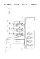
- FIG. 1is a simplified schematic drawing illustrating one embodiment of a dispensing apparatus having features and advantages in accordance with the present invention
- FIG. 2is a front elevational view of an alternative embodiment of a dispensing apparatus having features and advantages in accordance with the present invention and incorporating a multi-head dispenser;
- FIG. 3is a cross-sectional view of a solenoid valve dispensing head for use in accordance with either of the embodiments of FIGS. 1 or 2;
- FIG. 4is a cross-sectional view of a positive-displacement syringe pump for use in accordance with either of the embodiments of FIGS. 1 or 2;
- FIG. 5is a graph illustrating initial (non-steady-state) dispense volumes versus target dispense volumes for a reagent dispensing method and apparatus in accordance with one preferred embodiment of the invention and showing the effects of reagent pre-pressurization;
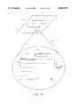
- FIG. 6is a schematic drawing illustrating a preferred method of depositing an array or pattern of reagent onto a substrate and having features and advantages in accordance with one embodiment of the present invention
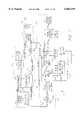
- FIG. 7is a detailed partial schematic circuit diagram of a control system for a reagent dispensing apparatus having features and advantages in accordance with the present invention.
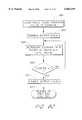
- FIG. 8is a simplified flow chart illustrating a preferred mode of operation of a dispenser apparatus having features and advantages in accordance with one embodiment of the present invention
- FIGS. 9A-Care detailed flow charts illustrating in more detail the preferred mode of operation of a dispenser apparatus having features and advantages in accordance with one embodiment of the present invention.
- FIG. 10Ais a schematic drawing illustrating an example of programmed mode line dispensing in accordance with one embodiment of the present invention, such as for creating custom dot array patterns on a membrane or glass slide;
- FIG. 10Bis a schematic drawing illustrating an example of synchronized line dispensing in accordance with one embodiment of the present invention, such as for creating high-density dot arrays on a membrane or glass slide;
- FIG. 10Cis a schematic drawing illustrating an example of synchronized line dispensing in accordance with one embodiment of the present invention such as for filling conventional micro-well plates;
- FIG. 10Dis a schematic drawing illustrating an example of non-synchronized line dispensing in accordance with one embodiment of the present invention such as for filling vision micro-well plates;
- FIG. 10Eis a schematic drawing illustrating an example of dot array mapping in accordance with one embodiment of the present invention, such as for mapping one or more micro-well plates onto a slide or other substrate.
- the syringe pumpmeters a predetermined quantity or flow rate of reagent to the dispenser to regulate the quantity or flow rate of liquid reagent dispensed.
- an associated X, X-Y or X-Y-Z tableis controlled so as to move a substrate in coordinated relation with the dispenser operation such that the reagent density can be controlled, for example, in terms of volume of reagent deposited per unit length of substrate substantially independently of the particular flow characteristics of the liquid reagent or the particular operating parameters of the dispenser (within a given range).
- the quantity or flow rate of reagentin series with the dispenser solved many of these problems by allowing the quantity or flow rate of reagent to be controlled independently of the particular flow characteristics of the liquid being dispensed and/or the operating parameters of the particular dispenser.
- the size of droplets formed by a dispensercan be adjusted by changing the operating frequency (for a solenoid valve or piezoelectric dispenser) or by adjusting the air pressure or exit orifice size (for an air brush dispenser) without affecting the flow rate of reagent.
- the reagent flow ratecan be controlled without substantial regard to the system operating parameters otherwise required to achieve stable dispensing operations.
- the quantity or flow rate of reagent dispensedis controlled or regulated independently by the positive displacement pump. In this manner, the invention provided not only an improved method for metering and dispensing of liquids, but also added a new dimension of dispenser operation and control never before possible.
- test strips or dip sticksfor ever more complex applications, such as for high-throughput drug and/or genetic screening, medical research and other custom applications.
- the commercial feasibility of manufacturing such test strips on a production levelhas also spurred technological advances in the test strips themselves and in the associated clinical chemistries and underlying diagnostics. These advances have further enhanced the commercial and clinical acceptance and viability of such test strips for home and clinical use in a wide variety of areas.
- the present inventionimproves and expands upon this earlier work by providing a high-speed dispensing apparatus and method for more precisely and repeatably depositing reagent onto a substrate or other receptive surface or receptacle.
- the disclosed apparatus and methodhave particular commercial advantage for dispensing complex and/or high-density patterns of reagent because it allows for precise dispensing "on-the-fly"--that is, without the need to alternately stop and start the X-Y carrier platform. As a result, higher “dot" densities, and even more complex patterns may be dispensed without significantly increasing production time or operating costs per strip.
- FIG. 1is a simplified schematic overview which illustrates one embodiment of such a dispensing apparatus 108 having features and advantages in accordance with the present invention.
- the dispensing apparatus 108generally comprises a dispensing head 128 having a valve or other dispensing means 204 operated by an actuator, such as solenoid.
- the dispensing head 128is mounted on or in association with an X-Y table or gantry 110.
- the X-Y table 110may include one or more position stepper motors 123, 124 or the like, which are operable to move either the dispensing head 128 and/or the carrier platform or table 112 relative to one another in the X, X-Y or X-Y-Z directions, as indicated in the drawing.
- dispensing head 128it is contemplated that multiple dispensing heads in linear or two-dimensional arrays can also be used with equal or improved efficacy. These may be provided and operated either in parallel as illustrated in FIG. 2 (ie. for multi-gang operation) or in another coordinated fashion, as desired.
- a positive displacement pump or other direct current fluid sourcesuch as syringe pump 120
- syringe pump 120is hydraulically coupled to a fluid reservoir 116 through a first one-way check valve 145.
- the syringe pump 120draws fluid 130 from the fluid reservoir 116 and provides it to the dispensing head 128 through a second check valve 145, as shown in FIG. 1.
- the syringe pump 120is operated by a syringe pump driver 142 comprising, for example, a stepper motor and an associated lead screw, for extending and retracting the piston 118 within the syringe barrel 362.
- a syringe pump driver 142comprising, for example, a stepper motor and an associated lead screw, for extending and retracting the piston 118 within the syringe barrel 362.
- reagent 130is forced to flow from the syringe barrel 362 into the dispensing head 128 via the supply tube 150, whereupon it is ejected by the dispensing head 128 onto the substrate 111 in the form of droplets 131.
- a controller 114oversees operation of the pump 120, X-Y table 110 (or X, or X-Y-Z table) and the dispensing head 128. Specifically, the controller 114 coordinates and controls the motion of each of the stepper motors 123, 124, and the syringe pump driver 142, as well as the opening and closing of the dispensing valve 204 to precisely dispense an amount of reagent at one or more predetermined location(s) on the substrate 111. As noted above, this dispensing operation takes place on-the-fly, that is without stopping the motion of the X-Y table.
- the controller 114calculates a phase adjustment for each dispense cycle.
- the phase adjustmentis such as to advance (or retard) the timing of the valve opening and closing so that the dispensed droplet of reagent 131 lands at the desired location on the substrate 111 (or at a desired offset location), taking into account its anticipated trajectory.
- the magnitude of the necessary or desired phase adjustmentwill depend, among other things, on a number of system input and output parameters and behavioral characteristics, including the desired drop offset (if any), the vertical distance between the dispensing head nozzle 205 and the surface of the substrate 111, the velocity and/or acceleration of the dispensing head 128 and/or the substrate 111 relative to one another, the velocity of the dispensed droplets, ambient temperature and humidity, and other controlled and/or uncontrolled factors. While certain of these parameters or characteristics can be isolated and studied such that their impact on the necessary phase adjustment is fairly predictable other parameters or characteristics can neither be isolated nor predicted.
- controller 114will be described in more detail below in connection with the description of FIGS. 7-10.
- FIG. 3is a cross-sectional view of a solenoid valve dispensing head 128 for use in accordance with either of the embodiments of FIGS. 1 or 2. While the selection of a particular dispensing head is not critical to practicing the present invention, it has been found that a solenoid actuated valve dispenser 128 provides good results when used in accordance with the teachings herein. Again, those skilled in the art will recognize that other types of dispensers and valve actuation devices exist and may be used with efficacy. These may include, for example, but are not limited to air brush dispensers, piezoelectric dispensers, fluid impulse dispensers, heat actuated dispensers, and the like.
- Solenoid valve dispensers of the type shown in FIG. 3are commonly used for inkjet printing applications and are commercially available from sources such as The Lee Company of Westbrook, Connecticut.
- the dispenser 128generally comprises a solenoid portion 202, a valve portion 204 and a nozzle portion 205.
- the solenoid portion 202comprises an electromagnetic coil or winding 206, a static core 238 and a movable plunger 240.
- the static core 238 and movable plunger 240are disposed within a hollow cylindrical sleeve 241 and are preferably spaced at least slightly away from the inner walls of the sleeve 241 so as to form an annular passage 242 there between through which the reagent 130 or other liquid to be dispensed may flow.
- the static core 238 and movable plunger 240are preferably formed of a ferrous or magnetic material, such as an iron alloy, and are separated by a small gap 244.
- a ferrous or magnetic materialsuch as an iron alloy
- the valve portion 204comprises a valve seat 252, having an orifice opening 254, and a stopper 256 having a valve face 258 adapted to seal against the valve seat 252.
- the stopper 256is in electromechanical communication with the plunger 240 and is spring biased toward the valve seat 252 via coil spring 260.
- the valve 234will open and close, accordingly.
- a volume of liquidis allowed to escape through the valve orifice 254. This forms an energy pulse or pressure wave which causes a droplet of liquid to be ejected from the exit orifice 261 of the nozzle tip 259.
- a pressurized reservoir(not shown) having a predetermined constant pressure is used to force reagent or other liquid through the valve orifice 254 during the time interval (or "duty cycle") in which the valve 234 is open.
- a pressurized reservoir(not shown) having a predetermined constant pressure is used to force reagent or other liquid through the valve orifice 254 during the time interval (or "duty cycle") in which the valve 234 is open.
- such dispensersmay have a repeatability as low as ⁇ 2% with a minimum drop size of about 30-35 nanoliters.
- the size of the dropletwill be determined by the system operating parameters such as the reservoir pressure, valve open time or duty-cycle, and the viscosity and other flow characteristics of the particular reagent or liquid being dispensed.
- a positive displacement pump 120(see eg., FIG. 1) is provided in series with the solenoid valve dispenser 128.
- Configuring the dispensing system in this mannerhas the benefit of forcing the solenoid valve dispenser 128 to admit and eject a quantity and/or flow rate of reagent as determined solely by the positive displacement pump 120, with which it is hydraulically in series.
- the syringe pumpcould be instructed to deliver a flow rate of 1 microliter per second of reagent to the solenoid valve dispenser 128 at a steady rate.
- the valve stopper 256is opened and closed at a given frequency and duty cycle a series of droplets are formed which will exactly match the desired flow rate.
- the syringe pumpacts as a forcing function for the entire system, ensuring that the desired flow rate is maintained regardless of the duty cycle or frequency of the dispensing valve.
- the frequency and/or velocity of the dropletscan be adjusted without affecting the flow rate of reagent simply by changing the frequency and/or duty cycle of the energizing pulses 182 (FIG. 1) provided to the solenoid valve dispenser.
- the frequency and/or duty cycle of the energizing pulses 182provided to the solenoid valve dispenser.
- valve open time or duty-cyclenecessary to achieve stable droplet formation. If the open time is too short relative to the flow rate, the pressure will increase and possibly prevent the valve dispenser 128 from functioning properly. If the open time is too long relative to the flow rate, then drop formation may be impaired or may not be uniform for each open/close cycle.
- a suitable syringe pump 120generally comprises a syringe housing 362 of a predetermined volume and a plunger 118 which is sealed against the syringe housing by O-rings or the like (not shown).
- the plunger 118mechanically engages a plunger shaft 366 having a lead screw portion 368 adapted to thread in and out of a base support (not shown).
- a pump driver 142including a stepper motor (FIG. 1) or other incremental or continuous actuator device is used so that the amount and/or flow rate of reagent 130 can be precisely regulated.
- syringe pumpsare commercially available.
- One such syringe pumpis the Bio-Dot CV1000 Syringe Pump Dispenser, available from Bio-Dot, Inc. of Irvine, Calif.
- This particular syringe pumpincorporates an electronically controlled stepper motor for providing precision liquid handling using a variety of syringe sizes.
- the CV1000is powered by a single 24 DC volt power supply and is controlled via an industry-standard RS232 or RS485 bus interface.
- the syringe pumpmay have anywhere from 3,000-24,000 steps, although higher resolution pumps having 48,000 steps or more may also be used to enjoy the benefits of the invention herein disclosed. Higher resolution pumps, such as piezoelectric motor driven pumps, may also be used to provide even finer resolutions as desired.
- the lead screw 368may optionally be fitted with an optical encoder or similar device to detect any lost steps.
- the lead screw of the metering pumpcan be replaced with a piezoelectric slide to provide both smaller volume increments and also faster acceleration/deceleration characteristics.
- Multiple syringe pumpsmay also be used in parallel, for example, for delivering varying concentrations of reagent 130 and/or other liquids to the dispenser or for alternating dispensing operations between two or more reagents. This could have application, for instance, to ink jet printing using one or more colored inks or liquid toners.
- the travel of the plunger 118is preferably about 260 mm.
- Plunger speedsmay range from 0.8 seconds per stroke with a 10-step minimum for low-resolution pumping or 1.5 seconds per stroke with a 20-step minimum for high-speed resolution pumping.
- the stroke speedmay vary depending upon the syringe size and the tubing used. Syringes may vary from less than 50 microliters to 25 milliliters, or more as needed. For most reagent dispensing applications it should be adequate to provide a syringe having a volume from about 50 microliters to about 25 milliliters. The minimum incremental displacement volume of the pump will depend on the pump resolution and syringe volume.
- the minimum incremental displacement volumewill be about 42 nanoliters.
- Minimum incremental displacement volumes from about 0.5 nanoliters to 2.1 millilitersare preferred, although higher or lower incremental displacement volumes may also be used while still enjoying the benefits of the present invention.
- the syringe housing 362may be made from any one of a number of suitable bio compatible materials such as glass, TeflonTM or Kel-F.
- the plunger 118is preferably formed of virgin TeflonTM.
- the syringe 120is connected to the reservoir 116 and the dispensing head 128 using a Teflon tubing 150, such as 1/4-inch O.D. tubing provided with luer-type fittings for connection to the syringe and dispenser.
- Various check valves 145may also be used, as desired or needed, to direct the flow of reagent 130 to and from the reservoir 118, syringe pump 120 and dispenser 128.
- FIG. 7illustrates one possible embodiment of an electronic controller 114 having features of the present invention.
- the controller 114 of the embodiment described hereingenerally comprises a host CPU 402 or computer which interfaces with some form of data memory.
- the controllermay be roughly divided into five basic subsystems: host CPU 402, coordinate control circuitry 404, memory and logic circuitry 406, syringe stop count circuit 408, and valve firing circuit 412.
- host CPU 402coordinate control circuitry 404
- memory and logic circuitry 406syringe stop count circuit 408, and valve firing circuit 412.
- Each of these subsystemsare illustrated schematically by phantom lines in FIG. 7 and are described in more detail below.
- Those skilled in the artwill appreciate that each subsystem works in cooperation with the other subsystems to simultaneously control the coordinate stepper motors 123, 124, the syringe pump motor 142 and the solenoid valve dispenser 128 (FIG. 1) to achieve the desired dispensing.
- a host CPU 402serves as the central controller and also the interface between the controller 114 and the user. It allows the operator to input dispensing data and to control, either independently or simultaneously, each aspect of the dispensing apparatus 108 (FIG. 1).
- the host CPU 402generally comprises a 80 ⁇ 86 or Pentium-based computer having a slot or bus compatible to accept a plug-in circuit board.
- the circuit board or "controller card”contains the four subsystems shown in FIG. 7.
- the controller cardmounts or plugs into a computer bus providing data transfer and communication of instructions.
- the host CPU 402also provides power to the controller card and further allows an operator to access, program and control the functions of the controller card. It is further contemplated that the host CPU 402 contains suitable computer software compatible with the host CPU and the controller card which facilitates operation of the system as described herein.
- a display device and data input meansare integral with the host CPU 402 thereby providing means to input data into a memory or static RAM array 414 located on the controller card and to verify the same using the display device.
- a keyboard, mouse, trackball, light pen, capacitance touch screen, computer storage mediaare all acceptable data input means.
- a color video monitor or screenprovides a suitable display means.
- a data entry devicesuch as a keyboard
- an operatormay enter data into the host CPU 402 in the form of a data array or graphical bit map to thereby instruct the electronic controller and dispensing apparatus of the desired reagent pattern and characteristics.
- Conventional computer softwaremay facilitate the entry of the data array or bit map via the host CPU 402 to the memory 414 of the controller card.
- the controller cardis compatible with a PC-AT clone, i.e. 80 ⁇ 86 or Pentium-based architecture.
- the controller card form factor and bus configurationmatch a PC-104 format, thereby allowing the circuit design to be quickly and inexpensively manufactured in a circuit board format.
- the host CPU 402utilizes a Motorola 68332 processor as the main microprocessor. However, as known by those skilled in the art, other computer systems and host CPU's may be used with equal advantage.
- a buscomprises an electrical connection which facilitates the exchange of information, such as address information, data information and/or instructions.
- the present inventionincludes an address bus 416 which carries address information, and a data bus 418 which carries data information.
- the data bus 418 and the address bus 416connect to the memory and logic circuitry 406.
- the data bus 418 and the address bus 416are bi-directional thereby allowing the transfer of data between the controller card and the memory and logic circuitry 406.
- the controller 114may display status information from the controller card on the video display of the host CPU 402 or alternatively, write the information to a data file on a permanent storage medium.
- other types of electrical connectionsexist which carry electronic information and are fully contemplated for use with the present invention.
- the memory and logic circuitry 406stores the data which defines the desired dispensing pattern and characteristics.
- Other hard-wired logic circuitrysuch as a counter 424 and multiplexer 426, may also be used, as desired, to parse dispensing data to the other subsystems of the controller 114 or to speed up the processing of information and control data.
- the memory and logic circuitry 406generally comprises an electronic memory 414 for storing data regarding reagent 130 dispense parameters, a tri-state buffer 420, a divisor 422, an address counter 424, a multiplexer 426 and various logic circuitry to assure proper operation of the electronic controller 114.
- the tri-state buffer 420connects to the host CPU 402 via the data bus 418 and serves to isolate the CPU from the controller card. The buffer is adapted to rapidly accept and store data to further increase data transfer speed and free the host CPU 402 of data transfer operations.
- the tri-state buffer 420connects to a memory module 414, preferably a static ram array.
- the tri-state buffer 420also connects to the output lines of the static ram array 414 for direct control of the syringe motor 142 and the solenoid valve dispenser 128 (FIG. 1).
- the static ram array 414comprises an electronic memory device which stores the data in the form of a data array sent from host CPU 402 via the tri-state buffer 420.
- the data array 414defines the reagent 130 dispensing pattern.
- access to each value in the data array 414corresponds to a data array address thereby allowing access to specific data in the data array.
- a 2:1 multiplexer 426connects via the address bus 416 to the host CPU 402
- the 2:1 multiplexer 426allows the operator to select which of the two inputs pass the the output.
- the multiplexer 426has two inputs: a first input which connects to the output of the counter 424 and a second input which connects to the address bus 416
- the multiplexer 426provides a data array address from the host CPU 402 or, during steady state operation, from the output of the memory and logic circuitry counter 424.
- the multiplexer 426passes the counter output to the static RAM array 414, the address increments automatically by way of a stepper control chip output.
- the output of the stepper control chip 430advantageously serves as the main clock for the controller and thereby synchronizes operation of the system 108. A more detailed discussion of the stepper control chip 430 is provided below.
- the counter output 424provides one of the two inputs to the multiplexer 426.
- a counter 424comprises digital logic circuit which records input pulses to produce a binary word that increases or decreases in value by a predetermined number (preferably 1) upon each input pulse. This binary word provides the next address for retrieving data from the data array.
- the counter 424operates to increment the address of the data array 414.
- the counter 424is preferably a resettable circuit and a reset line 425 is provided from the miscellaneous register and logic 428 to reset the counter 424.
- the counter 424may also be reset either automatically or manually via an interrupt (not shown) from the host CPU 402.
- the output of divisor circuitry 422provides input to the counter 424.
- the divisor 422provides an output after receiving N number of input pulses, where N is the number of input pulses required to trigger an output pulse. If desired, the divisor 422 can be user adjustable so that the value for N may be set by the operator. Thus, the resolution of the dispensing apparatus may be controlled by the number of pulses output by the stepper control chip 430 and the value assigned to N.
- a divisor 422can readily be implemented using a form of a counter circuit wherein the counter circuit outputs a pulse upon receipt of a certain number of input pulses.
- the input to the divisor 422is the main clock signal provided by the stepper control chip 430.
- the divisor circuit 422also provides output to the syringe stop count circuit 408 and the valve firing circuit 412, described below.
- Dual output lines from the static ram array 414connect to each of the syringe stop count circuit 408 and the valve single shot circuit 412, both of which are described in more detail below.
- the output of the static ram array 414defines the desired syringe motor increment and the valve pulse duration and is sequentially incremented by the address counter input.
- miscellaneous registers and logicare integral with the above described componentry.
- various logic circuitry and storage registers 428are interspersed with the componentry described herein as appropriate.
- much of the electronic hardware described hereincould easily be embodied through the use of suitable software, as desired or appropriate.
- Coordinate control circuitry 404moves the dispensing head 128 (FIG. 1) to each desired location. While FIG. 7 only shows circuitry for X axis motion control, those skilled in the art will readily appreciate that Y axis motor control is also contemplated with the present invention to facilitate operation with an X-Y table. In another embodiment, the controller 114 may also incorporate Z axis motion to achieve compatibility with an X-Y-Z table. This provides additional control of the system by providing means to vary the distance between the dispensing head 128 and the substrate 111 (FIG. 1).
- the coordinate control circuitry 404generally comprises a stepper control chip 430, control logic 446 and an axis motor driver 448. As discussed in greater detail below, the coordinate control circuitry 404 provides input to the divisor 422 of the memory and logic circuitry 406. The coordinate control circuitry 404 also provides control of an axis stepper motor 123 (FIG. 1) and input to the syringe stop count circuit 408 and the valve firing circuit 412.
- the stepper control chip 430generates a constant step pulse output. This step pulse output serves dual purposes. First, the step pulse provides a control signal to the axis motor drive 443 which in turn powers the stepper motor 123. The stepper motor controls the dispensing head position along the X-axis. Second, the step pulse, or a divided form thereof, propagates throughout the system as the main clock pulse.
- the stepper control chip 430is of the type often used to operate stepper motors. The preferred embodiment described herein utilizes a Nippon Pulse PCL-240AK available from the Nippon Pulse Motor Co., Ltd, although other stepper motor control chips are currently available and are operational with the invention disclosed herein.
- the stepper control chip 430has two outputs: a step pulse output 450 and a direction signal output 452.
- the first output, the step pulse output 450connects to at least one logic device to regulate the operation of the step motor 123.
- the logic devicecomprise a dual-input AND gate 446.
- One input of the AND gate 446connects to the step pulse output 450 from the stepper control chip 430.
- An axis enable line 453connects to the other input of the AND gate 446.
- the axis enable signalwhen high, allows the step pulse output to propagate to the output of the AND gate 446.
- the memory and logic circuitry 406, described above,provides the axis enable signal to the AND gate 446 thereby providing means to cease movement of the dispensing head 128, either automatically via the data array or manually via the host CPU 402.
- the second output of the stepper control chip 430, the motor direction control signal,is provided on a direction control line 452 to control the direction of the X axis stepper motor 123.
- the motor direction line 452which carries the motor direction signal, connects directly to the axis motor driver 448.
- the stepper motor direction signalis also fed to the syringe stop count circuit 408, described in more detail below. Changing the state or logic level of the direction line, changes the direction of the X-axis stepper motor 123. This advantageously provides for bidirectional printing which, as noted above, speeds dispensing operation.
- An axis motor driver 448receives the output from the AND gate 446 and the stepper control chip 430.
- the axis motor driver 440is an electronic device controlled by normal logic level signals which correlates the logic level input signals into a specialized output having increased current sourcing ability to drive a stepper motor. As is known by those of ordinary skill in the art many different axis motor drivers are available which satisfy the needs of the current invention.
- the output of the axis motor driver 448is provided to the X-axis stepper motor 123.
- the stepper motor 123controls movement of the dispensing head 128 in relation to the substrate 111 (FIG. 1).
- the stepper control chip 430, axis motor driver 448, and stepper motor 123have resolution of greater than about a hundred steps per linear inch, more preferably greater than about five hundred steps per linear inch, even most preferably greater than about seven hundred fifty steps per linear inch.
- the syringe stop count circuit 408controls the syringe 120 based on signals received from the stepper control chip 430 and the memory and logic circuitry 406.
- the syringe stop count circuit 408comprises control logic, a syringe circuit divisor 455, a syringe circuit counter 456, and a syringe motor driver 458.
- the syringe stop count circuit 408is synchronized with the other subsystems of the controller 114 to ensure precise and synchronized control over syringe motor driver 458.
- the control logicprovides means to obtain manual control over the syringe and includes a direction control NOR gate 460 which has two inputs, the first of which connects to the direction line 452 of the stepper control chip 430 and the second of which connects to a syringe direction invert line 462.
- the syringe direction invert line 462although not shown, connects to the memory and logic circuitry 406 and is discussed in more detail below.
- the output of the direction control NOR gate 460connects to the syringe motor driver 458, described below. Based on the signals entering the NOR gate 460 the syringe motor driver can be made to change the direction of the syringe stepper motor 142.
- the syringe motor 142is bi-directional thereby providing means to draw liquid into the syringe or expel liquid from the syringe 120.
- the syringe direction invert signalmay be provided, for example, in accordance with data contained in the static ram array 414 and thus may operate based on initial programming.
- the motion of the syringe plunger 118(FIG. 1) also reverses direction.
- the values in the static ram array 414may exist to ensure bi-directional printing, i.e. the level of the signal on the direction invert line 462 changes when the direction of the stepper motor 123 changes.
- an operatormay manually control the direction of the syringe 120 (FIG. 1) through the host CPU 402 via the direction invert line 462.
- Manual control over the syringe 120provides the operator with the ability to aspirate, dispense or fill the syringe 120 to achieve unique dispensing operations on a non-automated basis.
- the syringe stop count circuit 408also contains a syringe circuit counter 456.
- the syringe circuit counter 456determines the number of pulses to be provided to the syringe motor during a discreet dispense operation.
- the syringe circuit counter 456has three inputs 465, 466, 467 and an output 464.
- the first input 465accepts the syringe increment value from the static RAM array 414.
- the syringe increment valueis the number of steps the syringe motor 142 (FIG. 1) will move at a particular target location.
- the second input 466accepts the output of the divisor 422 from the memory and logic circuitry divisor 422.
- the divisor outputacts as the main clock for the syringe circuitry counter 456 thereby synchronizing the counter's output to each rising pulse of the divisor output.
- the counter's third input 467is a tap to monitor the pulses arriving at the syringe motor driver 458 and thereby count down the value at the counter.
- the syringe circuit counter 456obtains a value from the data array, in this case the number of steps the syringe 120 is to increment, and in response to each upward edge of the main clock signal, provides an equal number of pulses to an output 454.
- the output 454 of the counter 456feeds to the three part logic network of the syringe stop count circuit 408.
- the logic networksynchronizes operation of the syringe 120 (FIG. 1) with the position stepper motor 123 and provides manual control for a user to inhibit operation of the syringe.
- the logic networkcomprises a syringe override OR gate 470, an AND gate 471, and a syringe inhibitor AND gate 472.
- the syringe override OR 470 gatehas a first input connected to the counter output 454 described above.
- the syringe override OR gate 470has a second input connected to a syringe override signal line 474, which provides means to manually operate the syringe motor 142.
- the data array in the static RAM array 414may provide the syringe override signal, or alternatively, in manual control mode, the host CPU 402 may provide the syringe override signal via the memory and logic circuitry 406.
- the output of the syringe override OR gate 470connects to a first input of an AND gate 471.
- the second input of the AND gateconnects directly to the output of the stepper control chip 430.
- the AND gate 471allows for syringe motor signal propagation from either the syringe override signal or, during automatic operation based on the values from the static ram array 414.
- the output of the AND gate 471connects to a first input of a syringe inhibit AND gate 472.
- the second input to the syringe inhibit AND gate 472comprises a syringe inhibit signal line 476, which provides means to cease operation of the syringe motor 142.
- the data array in the static RAM array 414provides the syringe inhibit signal, or when the dispenser is under manual control, the host CPU 402 provides the syringe inhibit signal.
- the output of the syringe inhibit AND gate 472enters a syringe circuitry divisor 455.
- the divisor 455is identical to the divisor described above in the memory and logic circuitry 406, and thus is not described in detail again.
- the divisor 455provides an output pulse for every N number of input pulses, when N determines the resolution of the system.
- the divisor 455provides its output to the syringe circuitry counter 467 and the input of the syringe motor driver 458.
- the syringe motor driver 458operates substantially in accordance with the principles of the previously described axis motor driver 448 of the coordinate control circuitry 404 and therefore will not be repeated here.
- FIG. 5 line 910illustrates transient dispense effects caused by initial start-up operation of a dispensing apparatus.
- the controller of the present inventionpreferably provides pre-pressurization of the supply line 150 prior to initiating dispensing operations.
- Pre-pressurizationmay be achieved, for example, by advancing the syringe 120 while the valve 204 (FIG. 3) is closed in order to build up pressure in the line 150 to its predetermined steady-state level. Accordingly, when the valve 204 opens, the reagent 130 exits the valve at the desired target or steady-state rate or velocity.
- the amount of pre-pressurization needed to achieve steady-state operationcan be determined empirically for a given production set-up. For example, FIG. 5 illustrates the effect of varying amounts of pre-pressurization on start-up transient dispensing operations.
- pressure compensation techniquesmay also be used with efficacy, such as pressure sensor(s), time-domain compensation, syringe displacement compensation and the like.
- Valve firing circuit 412controls and synchronizes operation of the dispensing head 128 in coordination with the remaining subsystems of the dispensing apparatus 108 (FIG. 1).
- the valve firing circuit 412comprises a valve pulse counter 480, a reference clock 482, and a valve driver 484.
- the valve firing circuit 412obtains two input signals.
- the first input, from the memory and logic circuitry 406,comprises a valve pulse value from the static RAM array 414.
- the valve pulse valueis the time or number of click cycles the valve is to remain open.
- the second inputcomprises the main clock pulse from the output of the memory and logic circuitry divisor 422.
- the main clock pulseserves to synchronize operation of the valve with the rest of the dispensing apparatus.
- the pulse counter 480is responsible for providing the proper pulse duration to the valve driver 484.
- valve firing circuitryincludes a reference clock.
- the reference clockgenerates pulses of constant time duration. These pulses of constant time duration provide a known time reference on which the counter may base its operation. Since the valve pulse duration is in units of time, the reference clock 482 ensures accurate operation of the dispensing head 128 (FIGS. 1, 3).
- the output of the pulse counter 480connects to a valve driver 484.
- the valve driver 484receives the logic level input from the pulse counter 480 and provides a driving voltage for driving a solenoid or other such device to open and close the valve 204 of the solenoid valve dispenser 128 (FIG. 3). Accordingly, the valve driver 484 electrically communicates with the solenoid valve dispenser 202.
- FIG. 8is a flow chart illustrating the basic operation of a dispenser apparatus and control system as described herein.
- the first step 604comprises providing the reagent pattern and application requirements/parameters to the controller.
- the datais preferably entered in table or graphic form in a data file or bit map graphic file.
- the reagent application requirementsdefine the location and amount and the application characteristics of the dispensing process. This may be inputted by the operator via a keyboard or graphic interface or it may be loaded directly from a storage media, such as magnetic disk or tape.
- the systemtranslates the application requirements into syringe displacement and valve pulse duration values and arranges the calculated values in a data array.
- the data arraymay contain data values which govern the manner in which reagent is dispensed at a particular target location.
- each data addresscorresponds to a target location and consequently each target location has a plurality of corresponding values which define the dispensing characteristics for that location.
- the syringe displacement value and the valve pulse value for each dispense locationcorresponds to an address in the data array.
- the controller 114moves the dispensing head 128 across the substrate 111, the address in the data array is sequentially incremented thereby progressing through the values in the data array. This provides precise control over the amount of reagent and the manner in which the reagent is provided to each location on the substrate 111. All of this occurs simultaneously with the continuous motion of the dispensing head as it travels across the substrate.
- Adjustmentsmay include estimated adjustments for fluid viscosity, fluid temperature, dispensing apparatus configuration, substrate composition and other parameters. Adjustments may also include compensation for the velocity of dispensing head for X-axis and/or Y-axis travel. For example, if the dispensing head is moving at a high velocity, the pulsing of the valve and syringe must be phased slightly ahead of the desired dispensing location in order to hit the desired target area given the anticipated trajectory. Likewise, a more viscous liquid may require additional phase adjustments or an increase in the valve pulse time and the syringe increment distance so that the proper amount of reagent exits the valve.
- adjustmentsmay be determined through empirical studies and/or experimentally for a given reagent or production set-up. For example, rough adjustments can be made to the dispense data based on known or determined parametric equations or look-up tables in order to adjust for temperature, viscosity, height or speed of the dispensing head, etc. Finer adjustments can then be made experimentally for a given production set up. This can be done, for example, by programming the dispensing apparatus to dispense known patterns of crossing or parallel lines, target patterns and/or the like, at particular locations on the substrate. By inspecting the resulting patterns, certain adjustments, such as phase lead or lag, can be made to the dispense data to compensate for noted errors. The experiment can be repeated as many times as needed.
- sensorsmay be provided, such as temperature probes, viscosity sensing devices or other sensor devices, in order to provide real time automated feedback and adjustment of the dispenser.
- the controlleraligns the reagent dispensing head in its starting position.
- the dispensing head 128traverses the substrate.
- the controller 114increments the syringe 120 (FIG. 1), pulses the solenoid valve dispenser 128 (FIGS. 1, 3) and successively increments the data array address to provide precision on-the-fly reagent dispensing.
- FIG. 9Ais a flow chart illustrating, in more detail, one preferred mode of operation of a dispenser apparatus in accordance with the present invention.
- the host CPU 402receives data which governs the dispensing for a particular reagent and dispensing operation.
- a kROM, or other data entrskette, CD-ROM, or other data entry devicemay provide this information to the host CPU 402.
- the host CPU 402 or controller 114also receives the value by which the main clock signal will be divided (represented above by the letter N), step 812. This generally determines the resolution of the dispensing operation in terms of the number of addressable target areas per linear distance "d".
- the host CPU 402transfers the dispensing data to the static RAM array 414 (FIG. 7) of the electronic controller.
- the host CPU 402in conjunction with the static RAM array 414 places the data into a data array.
- the data arraycontains the dispensing data for each target location 706 (FIG. 3) and is accessed via a data address location.
- the data arraymay also contain specific control information such as syringe inhibit, syringe override, valve inhibit, valve override and stepper motor direction, if such information is applicable, and/or various adjustments.
- the system controller 114monitors the external sensors and/or operator input. Monitoring the external sensors may reveal additional information such as fluid viscosity and/or temperature. Based on the data from the external sensors and any final changes from the operator, the controller 114 adjusts the data array at step 820. For example, if the reagent is determined to be of higher than normal temperature, the valve duly cycle may be adjusted downward to ensure the proper amount of reagent is expelled.
- the stepper control chip 430begins operation by outputting a series of pulses.
- the stepper control chip 430, or some other equivalent output deviceprovides a pulse to the X axis driver 448 (FIG. 7) thereby actuating the X-axis stepper motor 123 (FIG. 1) which continuously moves the dispensing head 128 (FIG. 1) across the substrate 111.
- the dispensing head 128assumes a site of continual steady-state motion because of the high definition of the steps.
- the divided stepper control chip output pulsesserve as the main clock for the controller 114 of FIG. 7.
- other types of system synchronizersexist and are known by those of ordinary skill in the art.
- the main computer clock or a divided version thereofmay serve as the synchronizing signal.
- the operation of the controller 114branches and loops, as represented by the section 834 enclosed within the dashed line.
- the systemperforms several functions simultaneously, namely moving of the dispensing head 128, incrementing the syringe 120, and opening/closing the valve 204 (FIGS. 1, 3).
- the output of the stepper chip 430increments the address of the data array at which data is stored, step 836.
- the data in the data arraymay be arranged to cause the system 108 to dispense reagent 130 in a desired pattern, be it sequential or non-sequential, contiguous or non-contiguous.
- the dispensing head 128would only dispense reagent at the specific target locations on the substrate 111 indicated by the dispense data contained in the data array.
- the multiplexer 426(FIG. 7) and miscellaneous registers and logic (FIG. 7) access the syringe increment value 840 and the valve pulse value 844. These values are stored in the static ram array 414 (FIG. 7) and define how the syringe 120 will move and how long the valve 204 (FIG. 3) will remain open for a particular target location 706 (FIG. 6).
- the syringe increment valueis then transferred to a syringe stop count circuit, step 848.
- the valve pulse valueis transferred to a valve firing circuit, step 852.
- the sub-routines performed by these circuitscontrol the operation of the syringe 120 and valve 128 (both shown in FIG. 1) respectively.
- the operation of the syringe stop count circuit 848 and the valve firing circuit 852are described below in more detail.
- the controller 114queries for additional X axis data at step 854. If additional X axis data exists the system returns to step 836 to increment the address of the data array and repeat the above-described process. Conversely, if no additional data exist for a particular row, the controller 114 pauses the stepper control chip output, step 856, and queries whether additional rows of reagent 130 need to be dispensed, step 860. If data corresponding to additional rows exists in the data array, then the system increments the Y axis motor to thereby advance the dispensing head 128 (FIG. 1) one row, step 862, and returns to step 828 to dispense another row of reagent 130.
- the controller 114stops operation. The operator may then load another substrate 111, step 864, and repeat the dispensing process or input another dispensing pattern via the host CPU 402.
- the dispensing apparatus 108(FIG. 1), if equipped with an automatic substrate feed (not shown), may automatically load another substrate 111 upon completion of the process.
- FIG. 9Billustrates, in more detail, the preferred operation of the syringe stop count circuit 408 (FIG. 7).
- the syringe stop count circuit 408, shown in hardware in FIG. 7,controls the operation of the syringe 120 based on the values in the data array and the operation of the rest of the controller 114.
- the syringe increment valueobtained from the data array, loads into the syringe counter 456 (FIG. 7), step 870. If the syringe increment value is a non-zero value, the output of the counter 456 goes high to thereby enable the operation of the syringe driver, step 872.
- Each clock pulse of the divided stepper chip output 450(FIG.
- step 876the controller or host CPU queries the status of the counter 456. If the value of the counter has not reached zero, then the syringe stop count circuit 408 (FIG. 7) maintains the state of the counter output, in this embodiment high or enabled. As a result, the syringe 120 increments on the next divided main clock pulse and the counter decrements, step 874. Alternatively, if the query step determines that the counter value is zero, the output of the counter 456 is disabled, step 878, which in turn halts the advancement of the syringe 120. This completes the operation of the syringe for a particular target location. The operation of the controller 114 returns to FIG. 9A. The above described process repeats for each target location 706 (FIG. 3) on the substrate 111.
- FIG. 9Cillustrates, in more detail, the preferred operation of the valve firing circuit 412.
- the dashed line 412, valve firing circuit 412, shown in hardware in FIG. 7,comprises the hardware enclosed by the dashed line.
- the transferred valve pulse valueloads into the valve counter 480 (FIG. 7), step 884. If the valve pulse duration is a non-zero value, the output of the counter 480 goes high to thereby enable the operation of the valve driver 484 (FIG. 7), shown at step 886.
- the valve pulse counter 480(FIG. 7) operates in relation to a reference clock 482 (FIG. 7) to establish the reference period for the valve operation in units of time instead of number of pulses of the stepper control chip 430 (FIG. 7).
- the data arrayprovides information on how many reference clock pulses the valve 204 (FIG. 3) will remain open, which corresponds to a period of time and not the distance traveled by the X-axis stepper motor 123 (FIG. 1). For example, if each clock pulse lasts 0.001 seconds, then programming the valve to remain open for 100 reference clock pulses will result in the valve remaining open for 0.1 seconds or 1/10 of a second.
- the valve firing circuitdecrements the counter 480 on the next rising edge of the reference clock, step 888. This completes one clock cycle.
- a queryis made regarding the status of the counter. If the value of the counter 480 is non-zero, the valve firing circuit 412 maintains the state of the counter output, i.e., high or valve open. As a result, the valve 204 (FIGS. 1, 3) remains open and the counter 480 decrements on the next rising edge of the reference clock pulse, step 888.
- step 890determines that the counter value equals zero
- step 892which in turn disables the driver 484 (FIG. 7) and causes the valve 204 to close. This completes the valve operation for a particular target location 706.
- the operation of the systemprogresses in the fashion described in FIG. 9A step 894.
- the above described processrepeats for each target location 706 (FIG. 6) on substrate 111.
- the present inventionmay be configured to perform selective reagent dispensing operations.
- the system 108instead of configuring the system 108 for continuous linear motion of the dispensing head 128, the system can also provide for random access addressing of substrate target areas.
- the dispensing apparatus 108could, for example, dispense reagent at the upper right hand corner of a substrate 111 and then move to the lower left hand corner and dispense reagent without necessarily dispensing at any locations therebetween.
- the order and pattern of dispensingis automatically controlled via the data array or manually through the host CPU 402 (FIG. 7). An operator would configure the data array values to create a desired pattern of dispensed reagent 130. This pattern could provide, for example, a symbolic or textual representation indicating the test result, or form a visible brand or trade name on the substrate 111.
- EPROMscould store the computer code.
- Each EPROMcould connect to one or more microprocessors each of which would connect to one or more drivers to provide the appropriate signal to each electromechanical device.
- FIG. 2illustrates a single continuous feed platform 500 configured with multiple dispensers 512 to handle one or more reagents.
- This particular dispensing apparatus configurationhas significant advantages for continuous web production applications since one or more syringe pumps 512 can be operated in alternating succession while allowing the non-dispensing syringe pump to draw additional reagent from the reservoir or they can be configured independent of one another to dispense the same or different reagents simultaneously or in succession.
- a dispensing apparatus constructed in accordance with the present inventionmay also be mounted on any one of a number of other types of membrane placement and handling modules.
- Such dispensing platformsmay be microprocessor-based and are preferably controlled through an industry standard input/output I-O controller (not shown), such as an RS232 interface.
- I-O controllersuch as an RS232 interface.
- the inventionis also well suited for use with individual membrane strip handling modules and continuous reel-to-reel handling modules.
- an individual membrane strip modulemay incorporate only X-axis table motion for dispensing.
- the reel-to-reel platformmay incorporate a constant-speed membrane transport with optional mountings attached for motion of one or more dispensers.
- a drying oven(not shown) may also be used with any of the described embodiments to increase production throughput, as desired.
- FIG. 6shows a schematic view of a substrate 111, including an enlarged view illustrating how individual "dots" or droplets 702 might preferably be arranged on the substrate 111.
- the substrate 111is divided into rows (X-axis) 714 and columns (Y axis) 716 having a predetermined resolution in terms of a number of addressable target areas 706 per linear distance "d".
- a linear distance dequal to one inch (2.54 cm) of substrate 111 traveling along one axis may, for example, contain 100-500 or more individually addressable target locations.
- Each target locationwould correspond to a number of X-axis stepper motor increments and a number of Y-axis stepper motor increments relative to a predetermined "zero" position.
- FIG. 6illustrates one preferred pattern of dispensing motion in relation to the substrate 111. This pattern advantageously decreases the time to complete a particular dispensing operation.
- the dispensing headUpon executing a first linear pass 730 along a first row, the dispensing head reverses direction and executes a second pass 734 along an adjacent second row.
- Such bi-directional dispensingadvantageously decreases the time required to complete a dispensing operation in comparison to a unidirectional dispensing operation. It is also envisioned that for non-sequential or intermittent dispensing the controller would speed operation by dispatching the dispensing head directly to or adjacent the next desired target location without necessarily completing each successive pass or each intervening row.
- bit map graphics filesare easily generated and stored using any number of commercially available software editing programs, such as PC-PaintTM or the like.
- Modified graphics software specific to the implementation of this inventioncan also be provided for inputting and recording other relevant data, such as desired reagent density, droplet size, droplet velocity, and the like, for each particular dot address.
- the data file comprising the bit mapcan then be easily downloaded directly to a controller which, using suitable software and control techniques, directs the dispensing apparatus to create the desired reagent pattern having the specified characteristics.
- FIG. 10Ais a schematic drawing illustrating a programmed line mode of dispense operation in accordance with one embodiment of the present invention.
- individual dots of the same or different amounts of fluidmay be dispensed at different positions along a linear or non-linear path.
- the individual dotsmay or may not be colinear or evenly spaced, as desired. They may be spaced or offset from one another by a desired amount of spacing.
- This mode of operationmay be useful, for example, for creating custom dot array patterns on a membrane or glass slide.
- FIG. 10Bis a schematic drawing illustrating a synchronized mode of line dispense operation in accordance with one embodiment of the present invention, such as for creating high-density dot arrays on a membrane or glass slide.
- This mode of dispense operationis particularly suited for dispensing reagent or other fluids into a conventional well plate array, such as illustrated in FIG. 10C, using either a single or multi-head dispenser.
- a standard 96-well (8 ⁇ 12) well platemay be filled using a multi-head dispenser having a 1 ⁇ 8 dispense head array.
- the dispenserwould dispense 8 parallel lines of 12 drops each with a spacing of 9 mm between drops and a line length of 99 mm.
- the same dispensercould be used to dispense 8 parallel lines of 48 drops each with a spacing of 2.25 mm between drops and a line length of 105.75 mm.
- the line patternwould be repeated 4 times to fill the well plate.
- the same dispense modecould also be used to dispense droplet patterns onto an electronic biosensor array. These are usually fabricated using printed arrays of sensors or electrodes on a substrate. In this case the reagent is dispensed so as to match the sensor pattern. Again this can be done using a line mode similar to the case of the conventional micro-well plate as described above.
- FIG. 10Dis a schematic drawing illustrating a non-synchronized mode of line dispense operation in accordance with one embodiment of the present invention such as for creating continuous uniform lines on a flat substrate or for filling wells in a vision micro-well plate.
- a vision micro-well plateuses wells having an angular apex that separates each well. When dispensing a uniform continuous line of reagent the individual drops roll off the apex into the adjacent wells thus giving statistically accurate and even filling of wells.
- the present inventionimproves the ability to dispense uniform lines by eliminating communication and acceleration/deceleration problems.
- Conventional dispensing systemssuffer from a lack of uniformity in the spacing of droplets at the start and finish of a line forming operation. Uniformity is very important, particularly when dispensing short lines because the effects of starting and finishing each line can dominate the quality of the entire array if composed of short lines. This could cause unacceptable statistical variances, for example, when using a vision micro-well plate.
- FIG. 10Eis a schematic drawing illustrating a preferred mode of dot array mapping in accordance with one embodiment of the present invention. For example, it is often desirable to map (replicate or transform) one or more microplate arrays into a high density array on a membrane or glass slide. For instance, one could map sixteen 96-well well plates having 9 mm center-to-center well spacings into a single 1536 dot array having center-to-center spacings in the range of 100-1000 microns.
- This taskcan be accomplished several ways using the invention disclosed herein.
- One examplewould be to successively operate one head at a time of a 8-head dispenser with 9 mm center-to-center head spacing using a synchronous line dispense mode with a large spacing between drops.
- a common substrateis a standard 25 ⁇ 76 mm microscope slide.
- Onecan array 50 glass slides on an X-Y table and operate each of the 8 heads in succession to produce drops with a spacing in the range of 25 mm on each slide at the same position.
- the other 7 headscan be operated in linear succession with small offsets to produce an array of 8 dots on the glass slides with a small separation of between about 100-1000 microns between dots.
- this operationcan be done using one head at a time or, more preferably, using all 8 heads dispensing in rapid succession with small time delays to provide the desired linear spacing.
- the dispensercan also be programmed so as to transform one or more well plate arrays into a new or different high or low density array. For example, a series of two dimensional arrays may be transformed into rows or columns of a larger high-density array, or arrays may be transposed or inverted. Direct 1:1 mapping can also be achieved by operating the dispense heads in parallel synchronous line mode to produce 8 drops on each slide with a spacing of 9 mm. Other modes and variations for the use and operation of the invention will be apparent to those skilled in the art.
Landscapes
- Chemical & Material Sciences (AREA)
- Health & Medical Sciences (AREA)
- Organic Chemistry (AREA)
- Chemical Kinetics & Catalysis (AREA)
- Physics & Mathematics (AREA)
- Analytical Chemistry (AREA)
- Clinical Laboratory Science (AREA)
- Life Sciences & Earth Sciences (AREA)
- Fluid Mechanics (AREA)
- Biochemistry (AREA)
- General Health & Medical Sciences (AREA)
- General Physics & Mathematics (AREA)
- Immunology (AREA)
- Pathology (AREA)
- Automatic Analysis And Handling Materials Therefor (AREA)
- Application Of Or Painting With Fluid Materials (AREA)
- Electrostatic Spraying Apparatus (AREA)
- Spray Control Apparatus (AREA)
Abstract
Description
TABLE 1 ______________________________________DATA ADDRESS 1 2 3 4 5 6 7 8 . . . ______________________________________ SYRINGE INCREMENT VALUE VALVE PULSE VALUE X AXIS DIRECTION Y AXIS DIRECTION X AXIS VELOCITY COMPENSATION Y AXIS VELOCITY COMPENSATION SYRINGE DIRECTION INVERT SYRINGE OVERRIDE SYRINGE INHIBIT VALVE OVERRIDE PULSE INHIBIT REAGENT TEMPERATURE COMPENSATION REAGENT VISCOSITY COMPENSATION ______________________________________
Claims (27)
Priority Applications (11)
| Application Number | Priority Date | Filing Date | Title |
|---|---|---|---|
| US09/146,614US6063339A (en) | 1998-01-09 | 1998-09-03 | Method and apparatus for high-speed dot array dispensing |
| DE69940949TDE69940949D1 (en) | 1998-01-09 | 1999-01-05 | METHOD AND DEVICE FOR FAST MANUFACTURE OF A POINT MOTIF |
| CNB998026190ACN1152749C (en) | 1998-01-09 | 1999-01-05 | Method and apparatus for high-speed dot array dispensing |
| AU22119/99AAU2211999A (en) | 1998-01-09 | 1999-01-05 | Method and apparatus for high-speed dot array dispensing |
| JP2000527366AJP4435414B2 (en) | 1998-01-09 | 1999-01-05 | Liquid reagent dispenser |
| EP99902043AEP1044072B1 (en) | 1998-01-09 | 1999-01-05 | Method and apparatus for high-speed dot array dispensing |
| PCT/US1999/000092WO1999034931A1 (en) | 1998-01-09 | 1999-01-05 | Method and apparatus for high-speed dot array dispensing |
| US09/945,388US20020159919A1 (en) | 1998-01-09 | 2001-08-30 | Method and apparatus for high-speed microfluidic dispensing using text file control |
| US10/420,356US20040072364A1 (en) | 1998-01-09 | 2003-04-21 | Method for high-speed dot array dispensing |
| US10/765,001US20040219688A1 (en) | 1998-01-09 | 2004-01-26 | Method and apparatus for high-speed microfluidic dispensing using text file control |
| US11/332,857US20060211132A1 (en) | 1998-01-09 | 2006-01-13 | Method for high throughput drop dispensing of specific patterns |
Applications Claiming Priority (2)
| Application Number | Priority Date | Filing Date | Title |
|---|---|---|---|
| US7098898P | 1998-01-09 | 1998-01-09 | |
| US09/146,614US6063339A (en) | 1998-01-09 | 1998-09-03 | Method and apparatus for high-speed dot array dispensing |
Related Child Applications (2)
| Application Number | Title | Priority Date | Filing Date |
|---|---|---|---|
| US57145200ADivision | 1998-01-09 | 2000-05-16 | |
| US09/945,388DivisionUS20020159919A1 (en) | 1998-01-09 | 2001-08-30 | Method and apparatus for high-speed microfluidic dispensing using text file control |
Publications (1)
| Publication Number | Publication Date |
|---|---|
| US6063339Atrue US6063339A (en) | 2000-05-16 |
Family
ID=26751715
Family Applications (2)
| Application Number | Title | Priority Date | Filing Date |
|---|---|---|---|
| US09/146,614Expired - LifetimeUS6063339A (en) | 1998-01-09 | 1998-09-03 | Method and apparatus for high-speed dot array dispensing |
| US10/420,356AbandonedUS20040072364A1 (en) | 1998-01-09 | 2003-04-21 | Method for high-speed dot array dispensing |
Family Applications After (1)
| Application Number | Title | Priority Date | Filing Date |
|---|---|---|---|
| US10/420,356AbandonedUS20040072364A1 (en) | 1998-01-09 | 2003-04-21 | Method for high-speed dot array dispensing |
Country Status (7)
| Country | Link |
|---|---|
| US (2) | US6063339A (en) |
| EP (1) | EP1044072B1 (en) |
| JP (1) | JP4435414B2 (en) |
| CN (1) | CN1152749C (en) |
| AU (1) | AU2211999A (en) |
| DE (1) | DE69940949D1 (en) |
| WO (1) | WO1999034931A1 (en) |
Cited By (201)
| Publication number | Priority date | Publication date | Assignee | Title |
|---|---|---|---|---|
| US6232129B1 (en)* | 1999-02-03 | 2001-05-15 | Peter Wiktor | Piezoelectric pipetting device |
| WO2001052991A1 (en)* | 2000-01-21 | 2001-07-26 | Packard Instrument Company, Inc. | Dispensing liquid drops onto porous brittle substrates |
| EP1134586A1 (en)* | 2000-03-08 | 2001-09-19 | Tibotec N.V. | Method for adding a fluid in a series of wells |
| WO2001076755A1 (en)* | 2000-04-11 | 2001-10-18 | Haim Kedar | System and method for single or multiple bead distribution with an adjustable capillary |
| WO2001082013A1 (en)* | 2000-04-24 | 2001-11-01 | Pharmacopeia, Inc. | Single channel reformatter |
| US20010046699A1 (en)* | 2000-02-24 | 2001-11-29 | Hideji Tajima | Apparatus for positioning substances for detection and film for positioning substances for detection and manufacturing method of carrier for substances for detection |
| WO2002016040A1 (en)* | 2000-08-24 | 2002-02-28 | The University Of Chicago | A device for producing microscopic arrays of molecules, a method for producing microscopic arrays of molecules |
| WO2002018053A1 (en)* | 2000-08-30 | 2002-03-07 | Cartesian Technologies, Inc. | Method and apparatus for high-speed microfluidic dispensing using text file control |
| US6387330B1 (en)* | 2000-04-12 | 2002-05-14 | George Steven Bova | Method and apparatus for storing and dispensing reagents |
| WO2002040160A1 (en)* | 2000-11-17 | 2002-05-23 | Tecan Trading Ag | Device and method for separating samples from a liquid |
| WO2002040165A1 (en)* | 2000-11-17 | 2002-05-23 | Tecan Trading Ag | Device and system for dispensing or aspirating/dispensing liquid samples |
| US20020074342A1 (en)* | 2000-11-14 | 2002-06-20 | Shafer David A. | Expression miniarrays and uses thereof |
| US20020090320A1 (en)* | 2000-10-13 | 2002-07-11 | Irm Llc, A Delaware Limited Liability Company | High throughput processing system and method of using |
| US6420186B1 (en)* | 1997-10-14 | 2002-07-16 | A.R.T. Medical Instruments Ltd. | Method for depositing a flattened droplet on a surface and apparatus therefor, and a pump therefor |
| WO2002064255A1 (en)* | 2001-02-15 | 2002-08-22 | Scientific Generics Limited | Biochip array |
| US20020136668A1 (en)* | 1999-06-18 | 2002-09-26 | David Wallace | Apparatus and methods for high resolution separation and analysis of compounds |
| US20020142341A1 (en)* | 2001-03-28 | 2002-10-03 | Makoto Kameyama | Method and apparatus for producing probe carrier |
| US6461572B1 (en)* | 1998-06-04 | 2002-10-08 | Advanced Cardiovascular Systems, Inc. | Method and apparatus for concentrating a solute in solution with a solvent |
| US20020160370A1 (en)* | 2001-04-30 | 2002-10-31 | Bass Jay K. | Error detection in chemical array fabrication |
| US20020168297A1 (en)* | 2001-05-11 | 2002-11-14 | Igor Shvets | Method and device for dispensing of droplets |
| US20020182637A1 (en)* | 1999-06-18 | 2002-12-05 | Santarsiero Bernard D. | Method for screening microcrystallizations for crystal formation |
| US20030003221A1 (en)* | 2001-07-02 | 2003-01-02 | Zhong Sheng-Ping (Samuel) | Coating dispensing system and method using a solenoid head for coating medical devices |
| WO2002071051A3 (en)* | 2001-02-14 | 2003-01-09 | Picoliter Inc | Acoustic sample introduction for analysis and/or processing |
| US6512580B1 (en)* | 1999-10-27 | 2003-01-28 | Verification Technologies, Inc. | Method and apparatus for portable product authentication |
| US20030032198A1 (en)* | 2001-08-13 | 2003-02-13 | Symyx Technologies, Inc. | High throughput dispensing of fluids |
| EP1295643A1 (en)* | 2001-09-25 | 2003-03-26 | Ngk Insulators, Ltd. | Liquid droplet ejecting method and a liquid droplet ejection apparatus |
| US20030072679A1 (en)* | 2000-10-11 | 2003-04-17 | Innovadyne Technologies, Inc. | Universal non-contact dispense peripheral apparatus and method for a primary liquid handling device |
| US6550691B2 (en) | 2001-05-22 | 2003-04-22 | Steve Pence | Reagent dispenser head |
| US6551557B1 (en) | 1998-07-07 | 2003-04-22 | Cartesian Technologies, Inc. | Tip design and random access array for microfluidic transfer |
| US20030087444A1 (en)* | 2001-11-05 | 2003-05-08 | Industrial Technology Research Institute | Method and apparatus for manufacturing biochip |
| US6576295B2 (en) | 1996-07-26 | 2003-06-10 | Bio Dot, Inc. | Method for dispensing reagent onto substrate |
| US6589791B1 (en) | 1999-05-20 | 2003-07-08 | Cartesian Technologies, Inc. | State-variable control system |
| US6592822B1 (en)* | 1998-05-14 | 2003-07-15 | Luminex Corporation | Multi-analyte diagnostic system and computer implemented process for same |
| US6599479B1 (en)* | 1997-12-05 | 2003-07-29 | Max-Planck-Gesellschaft Zur Forderung Der Wissenschaften E.V. | Device and procedure for the electrically triggered microdrop release with a dispensing head |
| US20030143756A1 (en)* | 2002-01-30 | 2003-07-31 | Fisher William D. | Multi-directional deposition in array fabrication |
| US20030143329A1 (en)* | 2002-01-30 | 2003-07-31 | Shchegrova Svetlana V. | Error correction in array fabrication |
| US20030149933A1 (en)* | 2002-02-01 | 2003-08-07 | Marco Falcioni | Graphical design of chemical discovery processes |
| US6605257B1 (en)* | 1999-08-09 | 2003-08-12 | Thk Co., Ltd | Micro array manufacturing apparatus |
| EP1334770A1 (en)* | 2002-01-24 | 2003-08-13 | Packard Instrument Company, Inc. | Precision liquid dispensing system |
| US20030170903A1 (en)* | 2002-01-25 | 2003-09-11 | Innovadyne Technologies, Inc. | High performance, low volume, non-contact liquid dispensing apparatus and method |
| US6620383B1 (en) | 2000-02-29 | 2003-09-16 | Boston Innovation Inc. | Microvolume liquid dispensing device |
| EP1344565A1 (en)* | 2002-03-13 | 2003-09-17 | The Automation Partnership (Cambridge) Limited | Low volume droplet dispensing |
| WO2003078066A1 (en)* | 2002-03-13 | 2003-09-25 | The Automation Partnership (Cambridge) Limited | Low volume droplet dispensing |
| US20030203643A1 (en)* | 2002-03-13 | 2003-10-30 | Seiko Epson Corporation | Method and apparatus for fabricating a device, and the device and an electronic equipment |
| US20030207464A1 (en)* | 1999-02-19 | 2003-11-06 | Tony Lemmo | Methods for microfluidic aspirating and dispensing |
| US20030208936A1 (en)* | 2002-05-09 | 2003-11-13 | Lee Charles Hee | Method for manufacturing embroidery decorated cards and envelopes |
| US20030215957A1 (en)* | 1998-02-20 | 2003-11-20 | Tony Lemmo | Multi-channel dispensing system |
| US6659142B2 (en) | 2001-03-27 | 2003-12-09 | Irm, Llc | Apparatus and method for preparing fluid mixtures |
| US6669909B2 (en)* | 2001-03-26 | 2003-12-30 | Allegro Technologies Limited | Liquid droplet dispensing |
| US20040002164A1 (en)* | 2002-06-26 | 2004-01-01 | Timothy Chang | Delivery of metered amounts of liquid materials |
| WO2003059515A3 (en)* | 2002-01-18 | 2004-01-15 | Evotec Ag | Fluid conveying device and method for the introduction and withdrawal of fluids |
| US20040014029A1 (en)* | 2002-07-18 | 2004-01-22 | Mutz Mitchell W. | Acoustic radiation for ejecting and monitoring pathogenic fluids |
| US6706538B1 (en)* | 2000-02-29 | 2004-03-16 | Boston Innovation Inc. | Microvolume liquid dispensing array |
| US6709872B1 (en)* | 2000-05-02 | 2004-03-23 | Irm Llc | Method and apparatus for dispensing low nanoliter volumes of liquid while minimizing waste |
| US6713021B1 (en)* | 1999-11-11 | 2004-03-30 | The Provost, Fellows And Scholars Of The College Of The Holy And Undivided Trinity Of Queen Elizabeth Near Dublin | Dispensing method and assembly for liquid droplets |
| US20040073017A1 (en)* | 2002-02-27 | 2004-04-15 | Zbigniev Skrzypcznski | Surface modification, linker attachment, and polymerization methods |
| US6742549B1 (en)* | 2003-01-21 | 2004-06-01 | Fqubed | Method and apparatus for quasi-continuous and quasi-simultaneous dispensing |
| US20040129207A1 (en)* | 2002-12-20 | 2004-07-08 | Lg. Philips Lcd Co., Ltd. | Dispenser for liquid crystal display panel and dispensing method using the same |
| EP1445010A1 (en)* | 2003-02-05 | 2004-08-11 | The Automation Partnership (Cambridge) Limited | Degassification of fluids |
| US20040170762A1 (en)* | 2001-09-10 | 2004-09-02 | Christopher Newsome | Deposition of soluble materials |
| US20040203174A1 (en)* | 2003-04-11 | 2004-10-14 | Jones Aaron C. | Apparatus and methods for reformatting liquid samples |
| US20040219688A1 (en)* | 1998-01-09 | 2004-11-04 | Carl Churchill | Method and apparatus for high-speed microfluidic dispensing using text file control |
| US6814937B1 (en)* | 1999-10-22 | 2004-11-09 | Ngk Insulators, Ltd. | Dispenser and method for producing DNA chip |
| US20040228970A1 (en)* | 2003-02-14 | 2004-11-18 | Teruo Maruyama | Method and device for discharging fluid |
| US20040232162A1 (en)* | 2002-11-26 | 2004-11-25 | Cybio Ag | Apparatus for dispensing liquids |
| US20040247775A1 (en)* | 2003-06-06 | 2004-12-09 | Boulais Dennis R. | Positive displacement coating deposition apparatus and method |
| US20050003458A1 (en)* | 2003-06-12 | 2005-01-06 | Mathew Moore | Method and system for the analysis of high density cells samples |
| US6852291B1 (en) | 2000-10-11 | 2005-02-08 | Innovadyne Technologies, Inc. | Hybrid valve apparatus and method for fluid handling |
| US20050035143A1 (en)* | 2003-08-15 | 2005-02-17 | Peter Massaro | Method and apparatus for handling small volume fluid samples |
| US20050042381A1 (en)* | 2003-08-21 | 2005-02-24 | Thomas Weiss | Fully automated paste dispense system for dispensing small dots and lines |
| US6861034B1 (en)* | 2000-11-22 | 2005-03-01 | Xerox Corporation | Priming mechanisms for drop ejection devices |
| US20050052509A1 (en)* | 2003-08-29 | 2005-03-10 | Mark Peter Timothy Gilligan | Microfluidic system |
| US20050056713A1 (en)* | 2003-07-31 | 2005-03-17 | Tisone Thomas C. | Methods and systems for dispensing sub-microfluidic drops |
| US6904017B1 (en) | 2000-05-08 | 2005-06-07 | Lucent Technologies Inc. | Method and apparatus to provide centralized call admission control and load balancing for a voice-over-IP network |
| US20050122351A1 (en)* | 2003-10-28 | 2005-06-09 | Semiconductor Energy Laboratory Co., Ltd | Liquid droplet ejection system and control program of ejection condition of compositions |
| US20050163637A1 (en)* | 2003-12-04 | 2005-07-28 | Irm, Llc | Material conveying systems, computer program products, and methods |
| US20050214775A1 (en)* | 2004-03-26 | 2005-09-29 | Adaskin David R | Generalized pulse jet ejection head control model |
| US20050220675A1 (en)* | 2003-09-19 | 2005-10-06 | Reed Mark T | High density plate filler |
| US20050226782A1 (en)* | 2003-09-19 | 2005-10-13 | Reed Mark T | High density plate filler |
| US20050232822A1 (en)* | 2003-09-19 | 2005-10-20 | Reed Mark T | High density plate filler |
| US20050232820A1 (en)* | 2003-09-19 | 2005-10-20 | Reed Mark T | High density plate filler |
| US20050238543A1 (en)* | 2004-04-23 | 2005-10-27 | Giblin Leonard J | Metered dispenser and aspirator device |
| EP1357573A3 (en)* | 2002-04-24 | 2005-11-09 | Fujitsu Hitachi Plasma Display Limited | Fluorescent layer forming apparatus |
| US20050263398A1 (en)* | 2004-05-28 | 2005-12-01 | Hidekazu Tsudome | Micro fluidics system and treating method using same |
| US20060002824A1 (en)* | 2004-06-07 | 2006-01-05 | Irm, Llc | Dispensing systems, software, and related methods |
| US20060016830A1 (en)* | 2004-06-09 | 2006-01-26 | Smithkline Beecham Corporation | Apparatus and method for pharmaceutical production |
| US20060028503A1 (en)* | 2004-08-03 | 2006-02-09 | Semiconductor Energy Laboratory Co., Ltd. | Droplet discharge apparatus |
| US20060051250A1 (en)* | 2004-09-07 | 2006-03-09 | Gonzalez Jose M | Microtray for handling biosubstances |
| US20060097013A1 (en)* | 2003-04-28 | 2006-05-11 | Bargh Adrian N | Dispenser |
| EP1658894A1 (en) | 2002-02-22 | 2006-05-24 | Biodot, Inc. | Apparatus for dispersing reagent droplets below a fluid surface using non-contact dispensing |
| US20060205999A1 (en)* | 2002-04-22 | 2006-09-14 | Avraham Berger | Transportation of biological matter to a target site in a closed volume for transplantation purposes |
| WO2006099454A1 (en)* | 2005-03-14 | 2006-09-21 | Labcyte Inc. | Avoidance of bouncing and splashing in droplet-based fluid transport |
| US20060233670A1 (en)* | 2003-09-19 | 2006-10-19 | Lehto Dennis A | High density plate filler |
| US20060233671A1 (en)* | 2003-09-19 | 2006-10-19 | Beard Nigel P | High density plate filler |
| US20060233673A1 (en)* | 2003-09-19 | 2006-10-19 | Beard Nigel P | High density plate filler |
| US20060233672A1 (en)* | 2003-09-19 | 2006-10-19 | Reed Mark T | High density plate filler |
| US20060246599A1 (en)* | 2005-04-29 | 2006-11-02 | Sarah Rosenstein | Lateral flow device |
| US20060272738A1 (en)* | 2003-09-19 | 2006-12-07 | Gary Lim | High density plate filler |
| US20070026528A1 (en)* | 2002-05-30 | 2007-02-01 | Delucas Lawrence J | Method for screening crystallization conditions in solution crystal growth |
| US7199809B1 (en) | 1998-10-19 | 2007-04-03 | Symyx Technologies, Inc. | Graphic design of combinatorial material libraries |
| US20070105131A1 (en)* | 1990-12-06 | 2007-05-10 | Affymetrix, Inc. | Sequencing of surface immobilized polymers utilizing microfluorescence detection |
| US20070242105A1 (en)* | 2006-04-18 | 2007-10-18 | Vijay Srinivasan | Filler fluids for droplet operations |
| US7294309B1 (en) | 2003-05-15 | 2007-11-13 | Takeda San Diego, Inc. | Small volume liquid handling apparatus and method |
| US20070297279A1 (en)* | 2006-06-23 | 2007-12-27 | Jason Zhisheng Gao | Method of blending lubricants using positive displacement liquid-handling equipment |
| US20080007840A1 (en)* | 2006-07-05 | 2008-01-10 | Helicos Biosciences Corporation | Optical apparatus and methods for chemical analysis |
| US20080030721A1 (en)* | 2006-07-05 | 2008-02-07 | Helicos Biosciences Corporation | Optical apparatus and methods for chemical analysis |
| US20080131870A1 (en)* | 2006-06-09 | 2008-06-05 | Third Wave Technologies, Inc. | T-structure invasive cleavage assays, consistent nucleic acid dispensing, and low level target nucleic acid detection |
| US7396512B2 (en) | 2003-11-04 | 2008-07-08 | Drummond Scientific Company | Automatic precision non-contact open-loop fluid dispensing |
| US20080182340A1 (en)* | 2007-01-26 | 2008-07-31 | Lemmo Anthony V | Non-contact positive dispense solid powder sampling apparatus and method |
| US20080181834A1 (en)* | 1999-06-18 | 2008-07-31 | The Regiments Of The University Of California | Method for screening microcrystallizations for crystal formation |
| US7416709B1 (en) | 2003-12-31 | 2008-08-26 | Takeda San Diego, Inc. | Method for performing crystallization trials |
| US20080213132A1 (en)* | 2007-02-19 | 2008-09-04 | Shigenori Watari | Automatic analyzer |
| US20080237021A1 (en)* | 2007-03-30 | 2008-10-02 | Intermec Technologies Corporation | Keypad overlay membrane |
| US20080261326A1 (en)* | 2007-04-23 | 2008-10-23 | Christie Dudenhoefer | Drop-on-demand manufacturing of diagnostic test strips |
| US20080274513A1 (en)* | 2005-05-11 | 2008-11-06 | Shenderov Alexander D | Method and Device for Conducting Biochemical or Chemical Reactions at Multiple Temperatures |
| US20080274266A1 (en)* | 2007-05-02 | 2008-11-06 | Davis Liza J | Selective Application Of Therapeutic Agent to a Medical Device |
| US20090035795A1 (en)* | 2007-07-31 | 2009-02-05 | Christie Dudenhoefer | Method and composition for forming a uniform layer on a substrate |
| US20090180931A1 (en)* | 2007-09-17 | 2009-07-16 | Sequenom, Inc. | Integrated robotic sample transfer device |
| US20090205688A1 (en)* | 2006-02-02 | 2009-08-20 | Musashi Engineering, Inc. | Pallet for fixing work and liquid applying apparatus provided with same |
| US20100011889A1 (en)* | 2008-07-16 | 2010-01-21 | Biodot, Inc. | Handheld powder handling devices and related methods |
| US20100032293A1 (en)* | 2007-04-10 | 2010-02-11 | Advanced Liquid Logic, Inc. | Droplet Dispensing Device and Methods |
| US20100070069A1 (en)* | 2008-09-16 | 2010-03-18 | Ibis Biosciences, Inc. | Microplate handling systems and related computer program products and methods |
| US20100116640A1 (en)* | 2006-04-18 | 2010-05-13 | Advanced Liquid Logic, Inc. | Droplet-Based Surface Modification and Washing |
| US20100190263A1 (en)* | 2009-01-23 | 2010-07-29 | Advanced Liquid Logic, Inc. | Bubble Techniques for a Droplet Actuator |
| US20100312401A1 (en)* | 2009-06-08 | 2010-12-09 | Dresser, Inc. | Chemical Injection System |
| US20110091989A1 (en)* | 2006-04-18 | 2011-04-21 | Advanced Liquid Logic, Inc. | Method of Reducing Liquid Volume Surrounding Beads |
| US20110186433A1 (en)* | 2006-04-18 | 2011-08-04 | Advanced Liquid Logic, Inc. | Droplet-Based Particle Sorting |
| WO2011141357A1 (en) | 2010-05-12 | 2011-11-17 | Tecan Trading Ag | Dispenser and process for releasing flowable materials |
| US20120024888A1 (en)* | 2005-04-22 | 2012-02-02 | Allegro Research Limited | Cleaning of system for dispensing of liquid droplets |
| US20120045367A1 (en)* | 2010-08-23 | 2012-02-23 | Avia Biosystems, Llc | System for creation of formulations and generation of denaturation graphs |
| WO2012100205A2 (en) | 2011-01-21 | 2012-07-26 | Biodot, Inc. | Piezoelectric dispenser with a longitudinal transducer and replaceable capillary tube |
| US20120196374A1 (en)* | 2009-10-09 | 2012-08-02 | Beckman Coulter, Inc. | Dispenser, analyzer and dispensing method |
| WO2013040562A3 (en)* | 2011-09-15 | 2013-06-27 | Advanced Liquid Logic Inc | Microfluidic loading apparatus and methods |
| WO2014074456A1 (en) | 2012-11-06 | 2014-05-15 | Biodot, Inc. | Controlled printing of a cell sample for karyotyping |
| US20140170026A1 (en)* | 2012-12-18 | 2014-06-19 | Sony Corporation | Dispensing apparatus, analyzer and method for controlling dispensing apparatus |
| WO2014130576A1 (en) | 2013-02-19 | 2014-08-28 | Biodot, Inc. | Automated fish analysis of tissue and cell samples using an isolating barrier for precise dispensing of probe and other reagents on regions of interest |
| US8828655B2 (en) | 2007-03-22 | 2014-09-09 | Advanced Liquid Logic, Inc. | Method of conducting a droplet based enzymatic assay |
| US8846410B2 (en) | 2006-04-18 | 2014-09-30 | Advanced Liquid Logic, Inc. | Bead incubation and washing on a droplet actuator |
| US8845872B2 (en) | 2006-04-18 | 2014-09-30 | Advanced Liquid Logic, Inc. | Sample processing droplet actuator, system and method |
| US8852952B2 (en) | 2008-05-03 | 2014-10-07 | Advanced Liquid Logic, Inc. | Method of loading a droplet actuator |
| US8901043B2 (en) | 2011-07-06 | 2014-12-02 | Advanced Liquid Logic, Inc. | Systems for and methods of hybrid pyrosequencing |
| US20140354734A1 (en)* | 2013-06-04 | 2014-12-04 | The Regents Of The University Of California | Non-contact bio-printing |
| US8906627B2 (en) | 2002-09-24 | 2014-12-09 | Duke University | Apparatuses and methods for manipulating droplets |
| US20140360286A1 (en)* | 2012-01-17 | 2014-12-11 | The Scripps Research Institute | Apparatus and Method for Producing Specimens for Electron Microscopy |
| US8920752B2 (en) | 2007-01-19 | 2014-12-30 | Biodot, Inc. | Systems and methods for high speed array printing and hybridization |
| US8951732B2 (en) | 2007-06-22 | 2015-02-10 | Advanced Liquid Logic, Inc. | Droplet-based nucleic acid amplification in a temperature gradient |
| US20150090899A1 (en)* | 2012-01-17 | 2015-04-02 | The Scripps Research Institute | Preparation of Specimen Arrays on an EM Grid |
| US8999266B2 (en) | 2000-10-30 | 2015-04-07 | Agena Bioscience, Inc. | Method and apparatus for delivery of submicroliter volumes onto a substrate |
| US9012165B2 (en) | 2007-03-22 | 2015-04-21 | Advanced Liquid Logic, Inc. | Assay for B-galactosidase activity |
| US9011662B2 (en) | 2010-06-30 | 2015-04-21 | Advanced Liquid Logic, Inc. | Droplet actuator assemblies and methods of making same |
| US9050606B2 (en) | 2006-04-13 | 2015-06-09 | Advanced Liquid Logic, Inc. | Bead manipulation techniques |
| US9091649B2 (en) | 2009-11-06 | 2015-07-28 | Advanced Liquid Logic, Inc. | Integrated droplet actuator for gel; electrophoresis and molecular analysis |
| US9140635B2 (en) | 2011-05-10 | 2015-09-22 | Advanced Liquid Logic, Inc. | Assay for measuring enzymatic modification of a substrate by a glycoprotein having enzymatic activity |
| US9139865B2 (en) | 2006-04-18 | 2015-09-22 | Advanced Liquid Logic, Inc. | Droplet-based nucleic acid amplification method and apparatus |
| US9180450B2 (en) | 2002-09-24 | 2015-11-10 | Advanced Liquid Logic, Inc. | Droplet manipulation system and method |
| US9188615B2 (en) | 2011-05-09 | 2015-11-17 | Advanced Liquid Logic, Inc. | Microfluidic feedback using impedance detection |
| US20150331003A1 (en)* | 2010-05-14 | 2015-11-19 | Sias A/G | Pipetting Arrangement and Method of Controlling a Pipetting Arrangement or of Producing Liquid Product Doses |
| US9223317B2 (en) | 2012-06-14 | 2015-12-29 | Advanced Liquid Logic, Inc. | Droplet actuators that include molecular barrier coatings |
| US9222953B2 (en) | 2013-04-11 | 2015-12-29 | Rarecyte, Inc. | Device, system, and method for selecting a target analyte or fluid |
| US9238222B2 (en) | 2012-06-27 | 2016-01-19 | Advanced Liquid Logic, Inc. | Techniques and droplet actuator designs for reducing bubble formation |
| WO2016014976A1 (en) | 2014-07-25 | 2016-01-28 | Biodot, Inc. | Piezoelectric dispenser with a longitudinal transducer and replaceable capillary tube |
| US9248450B2 (en) | 2010-03-30 | 2016-02-02 | Advanced Liquid Logic, Inc. | Droplet operations platform |
| US20160039657A1 (en)* | 2014-08-08 | 2016-02-11 | Ajay Jain | Fluid dispensing device |
| US9267131B2 (en) | 2006-04-18 | 2016-02-23 | Advanced Liquid Logic, Inc. | Method of growing cells on a droplet actuator |
| US9321049B2 (en) | 2007-02-15 | 2016-04-26 | Advanced Liquid Logic, Inc. | Capacitance detection in a droplet actuator |
| US20160161773A1 (en)* | 2014-12-05 | 2016-06-09 | Beijing Boe Display Technology Co., Ltd. | Liquid crystal pump and method for ejecting liquid crystal using the same |
| US9377455B2 (en) | 2006-04-18 | 2016-06-28 | Advanced Liquid Logic, Inc | Manipulation of beads in droplets and methods for manipulating droplets |
| US9446404B2 (en) | 2011-07-25 | 2016-09-20 | Advanced Liquid Logic, Inc. | Droplet actuator apparatus and system |
| US9476856B2 (en) | 2006-04-13 | 2016-10-25 | Advanced Liquid Logic, Inc. | Droplet-based affinity assays |
| US9492820B2 (en) | 2003-09-19 | 2016-11-15 | Applied Biosystems, Llc | High density plate filler |
| US9511369B2 (en) | 2007-09-04 | 2016-12-06 | Advanced Liquid Logic, Inc. | Droplet actuator with improved top substrate |
| US9513253B2 (en) | 2011-07-11 | 2016-12-06 | Advanced Liquid Logic, Inc. | Droplet actuators and techniques for droplet-based enzymatic assays |
| US9545641B2 (en) | 2009-08-14 | 2017-01-17 | Advanced Liquid Logic, Inc. | Droplet actuator devices and methods |
| US9631244B2 (en) | 2007-10-17 | 2017-04-25 | Advanced Liquid Logic, Inc. | Reagent storage on a droplet actuator |
| US9630180B2 (en) | 2007-12-23 | 2017-04-25 | Advanced Liquid Logic, Inc. | Droplet actuator configurations and methods of conducting droplet operations |
| US20170131318A1 (en)* | 2003-10-24 | 2017-05-11 | Aushon Biosystems, Inc. | Apparatus and method for dispensing fluid, semi-solid and solid samples |
| US9675972B2 (en) | 2006-05-09 | 2017-06-13 | Advanced Liquid Logic, Inc. | Method of concentrating beads in a droplet |
| US20170172211A1 (en)* | 2015-12-22 | 2017-06-22 | Rui Nuno BATISTA | Aerosol-generating system with motor |
| US9863913B2 (en) | 2012-10-15 | 2018-01-09 | Advanced Liquid Logic, Inc. | Digital microfluidics cartridge and system for operating a flow cell |
| US20180071740A1 (en)* | 2015-05-29 | 2018-03-15 | Roche Diagnostics Operations, Inc. | Cartridge for dispensing particles and a reagent fluid |
| US20180221901A1 (en)* | 2015-09-18 | 2018-08-09 | Boe Technology Group Co., Ltd. | Sealant Coating Nozzle and Sealant Coating Apparatus |
| KR20180095807A (en)* | 2015-12-22 | 2018-08-28 | 필립모리스 프로덕츠 에스.에이. | Aerosol generating system with motor |
| US10078078B2 (en) | 2006-04-18 | 2018-09-18 | Advanced Liquid Logic, Inc. | Bead incubation and washing on a droplet actuator |
| US10139840B2 (en) | 2015-09-03 | 2018-11-27 | Horatio Quinones | System, device, and method for fluid dispensing control |
| WO2019017892A1 (en)* | 2017-07-18 | 2019-01-24 | Hewlett-Packard Development Company, L.P. | Reagent dispensing systems |
| WO2019017918A1 (en)* | 2017-07-18 | 2019-01-24 | Hewlett-Packard Development Company, L.P. | Reagent dispensing devices |
| US10379112B2 (en) | 2007-02-09 | 2019-08-13 | Advanced Liquid Logic, Inc. | Droplet actuator devices and methods employing magnetic beads |
| US10416046B2 (en) | 2013-04-11 | 2019-09-17 | Rarecyte, Inc. | Device, system, and method for selecting a target analyte |
| WO2019194790A1 (en)* | 2018-04-03 | 2019-10-10 | Hewlett-Packard Development Company, L.P. | Microfluidic channels to convey cells of different sizes |
| US20190389209A1 (en)* | 2018-04-27 | 2019-12-26 | Board Of Trustees Of The University Of Arkansas | High-Frequency Multi-Pulse Inkjet |
| US10731199B2 (en) | 2011-11-21 | 2020-08-04 | Advanced Liquid Logic, Inc. | Glucose-6-phosphate dehydrogenase assays |
| US10761104B2 (en) | 2016-05-11 | 2020-09-01 | Agilent Technologies, Inc. | Systems and methods for transferring liquids |
| US10794540B2 (en) | 2016-10-14 | 2020-10-06 | Marco Systemanalyse Und Entwicklung Gmbh | Apparatus and method for applying a fluid to an object surface |
| WO2021170524A1 (en) | 2020-02-25 | 2021-09-02 | Dna Script | Method and apparatus for enzymatic synthesis of polynucleotides |
| WO2021201858A1 (en)* | 2020-04-01 | 2021-10-07 | Hewlett-Packard Development Company, L.P. | Matrix dispense patterns |
| WO2021254934A1 (en) | 2020-06-16 | 2021-12-23 | Dna Script | Systems, apparatus and kits for enzymatic polynucleotide synthesis |
| US20230003723A1 (en)* | 2020-01-29 | 2023-01-05 | Hewlett-Packard Development Company, L.P. | Antibody fluid deposits |
| WO2023170286A2 (en) | 2022-03-11 | 2023-09-14 | Dna Script | Alignment post and secure mechanism for enzymatic polynucleotide synthesis |
| WO2023170258A1 (en) | 2022-03-11 | 2023-09-14 | Dna Script | Apparatus for enzymatic synthesis of a plurality of polynucleotides comprising a condensation trap |
| WO2023170259A1 (en) | 2022-03-11 | 2023-09-14 | Dna Script | Modular accessory rack |
| WO2023170266A1 (en) | 2022-03-11 | 2023-09-14 | Dna Script | Automation station for enzymatic polynucleotide synthesis |
Families Citing this family (51)
| Publication number | Priority date | Publication date | Assignee | Title |
|---|---|---|---|---|
| US6537505B1 (en) | 1998-02-20 | 2003-03-25 | Bio Dot, Inc. | Reagent dispensing valve |
| KR100691043B1 (en)* | 1998-05-09 | 2007-03-09 | 아이코니시스 인코포레이티드 | Computer Controlled Fetal Cell Inclusion Rare Cell Diagnostic Methods and Devices |
| WO1999067641A2 (en) | 1998-06-24 | 1999-12-29 | Illumina, Inc. | Decoding of array sensors with microspheres |
| US6846460B1 (en) | 1999-01-29 | 2005-01-25 | Illumina, Inc. | Apparatus and method for separation of liquid phases of different density and for fluorous phase organic syntheses |
| JP2001021558A (en)* | 1999-04-30 | 2001-01-26 | Agilent Technol Inc | Fabrication method of polynucleotide array |
| US7276336B1 (en) | 1999-07-22 | 2007-10-02 | Agilent Technologies, Inc. | Methods of fabricating an addressable array of biopolymer probes |
| WO2001012330A1 (en) | 1999-08-17 | 2001-02-22 | The Technology Partnership Plc | Flexible pipette strip and method of its use |
| US7390459B2 (en) | 1999-12-13 | 2008-06-24 | Illumina, Inc. | Oligonucleotide synthesizer |
| EP1239952B1 (en)* | 1999-12-13 | 2011-10-05 | Illumina, Inc. | Oligonucleotide synthesizer using centrifugal force |
| AU2001234739A1 (en)* | 2000-02-02 | 2001-08-14 | Cartesian Technologies, Inc. | Method and apparatus for developing dna microarrays |
| US6447723B1 (en) | 2000-03-13 | 2002-09-10 | Packard Instrument Company, Inc. | Microarray spotting instruments incorporating sensors and methods of using sensors for improving performance of microarray spotting instruments |
| WO2001071311A2 (en)* | 2000-03-17 | 2001-09-27 | Nanostream, Inc. | Electrostatic systems and methods for dispensing droplets |
| US6878554B1 (en) | 2000-03-20 | 2005-04-12 | Perkinelmer Las, Inc. | Method and apparatus for automatic pin detection in microarray spotting instruments |
| US7521245B1 (en) | 2000-06-05 | 2009-04-21 | Perkinelmer Las, Inc. | Method for washing and drying pins in microarray spotting instruments |
| CH695544A5 (en)* | 2000-11-17 | 2006-06-30 | Tecan Trading Ag | Apparatus for dispensing or aspirating / dispensing liquid samples. |
| JP4557450B2 (en)* | 2001-03-08 | 2010-10-06 | パナソニック株式会社 | Oxidant coating device |
| EP1308708B1 (en)* | 2001-11-01 | 2006-08-16 | Micromass UK Limited | Sample introduction system |
| US6991825B2 (en)* | 2002-05-10 | 2006-01-31 | Asm Assembly Automation Ltd. | Dispensation of controlled quantities of material onto a substrate |
| US8277753B2 (en) | 2002-08-23 | 2012-10-02 | Life Technologies Corporation | Microfluidic transfer pin |
| CA2513985C (en) | 2003-01-21 | 2012-05-29 | Illumina Inc. | Chemical reaction monitor |
| US20040151635A1 (en)* | 2003-01-31 | 2004-08-05 | Leproust Eric M. | Array fabrication using deposited drop splat size |
| US20040185169A1 (en)* | 2003-03-21 | 2004-09-23 | Peck Bill J. | Methods for fabricating biopolymer arrays |
| WO2007042964A1 (en)* | 2005-10-07 | 2007-04-19 | Koninklijke Philips Electronics N.V. | A method and apparatus for printing a pattern of distinct dots of different reagent fluids using a printing head comprising a set of nozzles |
| KR100776376B1 (en)* | 2006-02-15 | 2007-11-15 | 연세대학교 산학협력단 | Patterning device for forming conductive lines |
| JP4724570B2 (en)* | 2006-02-20 | 2011-07-13 | 武蔵エンジニアリング株式会社 | Liquid transfer device |
| US7832252B2 (en)* | 2006-10-05 | 2010-11-16 | Watson Gary W | Precise droplet injection for calibrating a gas chromatography instrument |
| US20090104078A1 (en)* | 2007-10-18 | 2009-04-23 | Matrix Technologies Corporation | Apparatus and method for dispensing small volume liquid samples |
| US8211370B2 (en) | 2007-12-07 | 2012-07-03 | Thomas Downing | Polymer synthesizer |
| US8609180B2 (en)* | 2007-12-10 | 2013-12-17 | Bayer Healthcare Llc | Method of depositing reagent material in a test sensor |
| DE102008058063A1 (en)* | 2008-11-18 | 2010-05-20 | Diasys Diagnostic Systems Gmbh | Automated analysis device with an automatic pipetting device and with two pumping units of different capacities |
| US8608937B2 (en) | 2009-03-30 | 2013-12-17 | Roche Diagnostics Operations, Inc. | Biosensor with predetermined dose response curve and method of manufacturing |
| EP2440942B1 (en) | 2009-06-09 | 2019-07-31 | GE Healthcare Bio-Sciences AB | Device and method for reducing loss of liquid during fraction collection |
| KR101156863B1 (en)* | 2010-06-28 | 2012-07-11 | 삼성전기주식회사 | Droplet discharging apparatus for cell counting |
| DE102010055019A1 (en) | 2010-12-17 | 2012-06-21 | Illinois Tool Works Inc. | Device for the intermittent application of a liquid to pasty medium on an application surface |
| EP2771128A4 (en)* | 2011-10-28 | 2015-09-30 | Hewlett Packard Development Co | Parallel addressing method |
| CN103376334B (en)* | 2012-04-25 | 2015-02-11 | 艾博生物医药(杭州)有限公司 | A liquid dispensing device |
| KR101436915B1 (en) | 2013-04-24 | 2014-09-02 | 연세대학교 산학협력단 | Diagnostic strip sensor fabrication device and thereof method |
| WO2017066546A1 (en)* | 2015-10-15 | 2017-04-20 | Board Of Regents, The University Of Texas System | Versatile process for precision nanoscale manufacturing |
| WO2017108429A1 (en) | 2015-12-22 | 2017-06-29 | Philip Morris Products S.A. | Aerosol-generating system with pump |
| US10398174B2 (en) | 2015-12-22 | 2019-09-03 | Altria Client Services Llc | Aerosol-generating system with pump |
| US10150115B2 (en)* | 2016-07-21 | 2018-12-11 | Spacepharma SA | System and method for rehydrating powder and delivering the rehydrated powder to a reactor |
| EP3820626A4 (en)* | 2018-11-02 | 2021-07-07 | Hewlett-Packard Development Company, L.P. | Randomized dispensing order |
| US11331660B2 (en)* | 2019-01-04 | 2022-05-17 | Funai Electric Co. Ltd. | Digital dispense system |
| KR102691534B1 (en)* | 2019-04-05 | 2024-08-02 | 주식회사 엘지에너지솔루션 | Apparatus for coating battery sheet |
| KR20220097454A (en)* | 2019-11-08 | 2022-07-07 | 브리스톨-마이어스 스큅 컴퍼니 | System for Determining the Accuracy of Series-Connected Drug Modules in a Combination Drug Delivery Device Using Voltage |
| CN110975957B (en)* | 2019-12-27 | 2025-02-07 | 苏州东杏表面技术有限公司 | A trace fluorine phase liquid dripping device |
| CN113134454B (en)* | 2020-01-20 | 2022-05-24 | 深圳硅基传感科技有限公司 | Drop coating device for sensing electrode |
| JP7433426B2 (en)* | 2020-05-22 | 2024-02-19 | 株式会社日立ハイテク | Automatic analyzer and its assembly support system |
| CN112974078B (en)* | 2021-02-03 | 2022-10-04 | 柳州市森东科技开发有限公司 | Mechanical part spraying mechanism |
| EP4406005A1 (en)* | 2021-09-23 | 2024-07-31 | The University of Vermont and State Agricultural College | Force-balanced meniscal dispensers for depositing crystalline layers, and methods of printing crystalline patterned features |
| WO2023047770A1 (en)* | 2021-09-24 | 2023-03-30 | 富士フイルム株式会社 | Pattern formation substrate production method and liquid discharge device |
Citations (15)
| Publication number | Priority date | Publication date | Assignee | Title |
|---|---|---|---|---|
| US2264564A (en)* | 1937-10-28 | 1941-12-02 | Connor Arthur Albert | Air brush for artists' use |
| US5056462A (en)* | 1989-11-27 | 1991-10-15 | Nordson Corporation | Coating system with correction for non-linear dispensing characteristics |
| US5324480A (en)* | 1992-12-04 | 1994-06-28 | Hamilton Company | Liquid handling system |
| US5334353A (en)* | 1993-02-03 | 1994-08-02 | Blattner Frederick R | Micropipette device |
| US5338688A (en)* | 1990-08-02 | 1994-08-16 | Boehringer Mannheim Gmbh | Method for the metered application of a biochemical analytical liquid to a target |
| US5509966A (en)* | 1993-10-22 | 1996-04-23 | Sykes; Richard H. | Graphic arts material extrusion device |
| US5593893A (en)* | 1994-03-15 | 1997-01-14 | Toa Medical Electronics Co., Ltd | Dispensing device with syringe driving compensator for flexible tube |
| US5601982A (en)* | 1995-02-07 | 1997-02-11 | Sargent; Jeannine P. | Method and apparatus for determining the sequence of polynucleotides |
| US5738728A (en)* | 1996-07-26 | 1998-04-14 | Bio Dot, Inc. | Precision metered aerosol dispensing apparatus |
| US5741554A (en)* | 1996-07-26 | 1998-04-21 | Bio Dot, Inc. | Method of dispensing a liquid reagent |
| US5743960A (en)* | 1996-07-26 | 1998-04-28 | Bio-Dot, Inc. | Precision metered solenoid valve dispenser |
| US5756050A (en)* | 1993-08-11 | 1998-05-26 | University Of Chicago | Device of dispensing micro doses of aqueous solutions of substances onto a carrier and device for carrying out said method |
| US5763278A (en)* | 1995-11-01 | 1998-06-09 | Tecan Ag | Automated pipetting of small volumes |
| US5770160A (en)* | 1995-09-15 | 1998-06-23 | Bio-Plas, Inc. | Positive displacement liquid drawing and dispensing apparatus |
| US5925732A (en)* | 1994-09-21 | 1999-07-20 | Isis Pharmaceuticals, Inc. | Chemical reaction apparatus for performing multiple reaction on a surface and collecting the product |
Family Cites Families (52)
| Publication number | Priority date | Publication date | Assignee | Title |
|---|---|---|---|---|
| US2512743A (en)* | 1946-04-01 | 1950-06-27 | Rca Corp | Jet sprayer actuated by supersonic waves |
| US3373437A (en)* | 1964-03-25 | 1968-03-12 | Richard G. Sweet | Fluid droplet recorder with a plurality of jets |
| US3452360A (en)* | 1967-07-28 | 1969-06-24 | Gen Precision Systems Inc | High-speed stylographic apparatus and system |
| US3512173A (en)* | 1967-12-28 | 1970-05-12 | Xerox Corp | Alphanumeric ink droplet recorder |
| US3946398A (en)* | 1970-06-29 | 1976-03-23 | Silonics, Inc. | Method and apparatus for recording with writing fluids and drop projection means therefor |
| GB1500908A (en)* | 1974-06-05 | 1978-02-15 | Ici Ltd | Process for production of drop streams |
| DE2658486C3 (en)* | 1976-12-23 | 1980-04-24 | Beckman Instruments Gmbh, 8000 Muenchen | Pipetting and dilution device for small amounts of liquid with direct digital setting of their volumes in milliliter and microliter units and with exchangeable piston pump modules |
| US4199013A (en)* | 1977-04-01 | 1980-04-22 | Packard Instrument Company, Inc. | Liquid sample aspirating and/or dispensing system |
| US4121466A (en)* | 1977-04-19 | 1978-10-24 | Technicon Instruments Corporation | Liquid dispenser with an improved probe |
| EP0007252A1 (en)* | 1978-04-28 | 1980-01-23 | S K M, Société Anonyme | Apparatus for delivering a fluid at constant flow, in particular for spray pistol |
| DE3070217D1 (en)* | 1979-10-31 | 1985-03-28 | Univ Birmingham | Improvements in or relating to pipette means |
| US4492322A (en)* | 1982-04-30 | 1985-01-08 | Indiana University Foundation | Device for the accurate dispensing of small volumes of liquid samples |
| US4478094A (en)* | 1983-01-21 | 1984-10-23 | Cetus Corporation | Liquid sample handling system |
| US4555957A (en)* | 1983-10-14 | 1985-12-03 | Cetus Corporation | Bi-directional liquid sample handling system |
| US4681742A (en)* | 1984-10-01 | 1987-07-21 | Cetus Corporation | Assay tray |
| AU585033B2 (en)* | 1986-07-04 | 1989-06-08 | Tosoh Corporation | Quantitative dispenser for a liquid |
| JPS6347665A (en)* | 1986-08-14 | 1988-02-29 | コントロン インスツルメンツ ホールディング エヌ.ブイ. | Method and device for operating pipet |
| US4922852A (en)* | 1986-10-30 | 1990-05-08 | Nordson Corporation | Apparatus for dispensing fluid materials |
| US4877745A (en)* | 1986-11-17 | 1989-10-31 | Abbott Laboratories | Apparatus and process for reagent fluid dispensing and printing |
| US5004159A (en)* | 1988-01-25 | 1991-04-02 | Specified Equipment Systems Company, Inc. | Method and apparatus for applying single of multicomponent materials |
| US5744101A (en)* | 1989-06-07 | 1998-04-28 | Affymax Technologies N.V. | Photolabile nucleoside protecting groups |
| US5257657A (en)* | 1990-07-11 | 1993-11-02 | Incre, Inc. | Method for producing a free-form solid-phase object from a material in the liquid phase |
| USH1099H (en)* | 1991-08-13 | 1992-09-01 | The United States Of America As Represented By The Secretary Of The Army | Liquid-drop generator |
| DE4202561A1 (en)* | 1992-01-30 | 1993-08-05 | Boehringer Mannheim Gmbh | DEVICE FOR DELIVERING AN ANALYZING LIQUID |
| JP3245256B2 (en)* | 1993-05-17 | 2002-01-07 | 株式会社リコー | Liquid resin dot forming apparatus, pattern image forming apparatus, substrate formed by these, and dot-like or pattern-like structure on substrate |
| US6203759B1 (en)* | 1996-05-31 | 2001-03-20 | Packard Instrument Company | Microvolume liquid handling system |
| US5558838A (en)* | 1993-09-29 | 1996-09-24 | Becton Dickinson And Company | Sample preparation apparatus |
| US5472672A (en)* | 1993-10-22 | 1995-12-05 | The Board Of Trustees Of The Leland Stanford Junior University | Apparatus and method for polymer synthesis using arrays |
| US5571639A (en)* | 1994-05-24 | 1996-11-05 | Affymax Technologies N.V. | Computer-aided engineering system for design of sequence arrays and lithographic masks |
| US5807522A (en)* | 1994-06-17 | 1998-09-15 | The Board Of Trustees Of The Leland Stanford Junior University | Methods for fabricating microarrays of biological samples |
| DE4428807C2 (en)* | 1994-08-13 | 1996-10-10 | Eastman Kodak Co | Device for speed and drop mass variation in thermal ink pens |
| US5601980A (en)* | 1994-09-23 | 1997-02-11 | Hewlett-Packard Company | Manufacturing method and apparatus for biological probe arrays using vision-assisted micropipetting |
| US5542289A (en)* | 1994-12-13 | 1996-08-06 | The Dow Chemical Company | Apparatus and method for the study of liquid-liquid interfacial rheology |
| US5750881A (en)* | 1995-07-13 | 1998-05-12 | Chiron Diagnostics Corporation | Method and apparatus for aspirating and dispensing sample fluids |
| US5811306A (en)* | 1995-09-04 | 1998-09-22 | Fuji Photo Film Co., Ltd. | Liquid spotting method |
| US5658802A (en)* | 1995-09-07 | 1997-08-19 | Microfab Technologies, Inc. | Method and apparatus for making miniaturized diagnostic arrays |
| US5741304A (en)* | 1995-10-17 | 1998-04-21 | University Of Kentucky Research Foundation | Multidirectional ECG coherent optimal timing of defibrillation shocks |
| US5747102A (en)* | 1995-11-16 | 1998-05-05 | Nordson Corporation | Method and apparatus for dispensing small amounts of liquid material |
| JPH09192574A (en)* | 1996-01-24 | 1997-07-29 | Matsushita Electric Ind Co Ltd | Thin film forming apparatus and thin film forming method |
| US5958342A (en)* | 1996-05-17 | 1999-09-28 | Incyte Pharmaceuticals, Inc. | Jet droplet device |
| EP0810438B1 (en)* | 1996-05-31 | 2004-02-04 | Packard Instrument Company, Inc. | Microvolume liquid handling system |
| US6083762A (en)* | 1996-05-31 | 2000-07-04 | Packard Instruments Company | Microvolume liquid handling system |
| US5770151A (en)* | 1996-06-05 | 1998-06-23 | Molecular Dynamics, Inc. | High-speed liquid deposition device for biological molecule array formation |
| CA2260840A1 (en)* | 1996-07-26 | 1998-02-05 | Thomas C. Tisone | Dispensing apparatus having improved dynamic range |
| US5916524A (en)* | 1997-07-23 | 1999-06-29 | Bio-Dot, Inc. | Dispensing apparatus having improved dynamic range |
| US5853894A (en)* | 1997-02-03 | 1998-12-29 | Cytonix Corporation | Laboratory vessel having hydrophobic coating and process for manufacturing same |
| FR2765338B1 (en)* | 1997-06-25 | 1999-07-23 | Inst Francais Du Petrole | DEVICE FOR SAMPLING AND/OR INJECTING A FLUID SAMPLE TO PRESERVE THE CHEMICAL AND/OR THERMODYNAMIC EQUILIBRIUM |
| US6537505B1 (en)* | 1998-02-20 | 2003-03-25 | Bio Dot, Inc. | Reagent dispensing valve |
| US7199809B1 (en)* | 1998-10-19 | 2007-04-03 | Symyx Technologies, Inc. | Graphic design of combinatorial material libraries |
| DE69931787T2 (en)* | 1999-11-11 | 2007-05-24 | The Provost, Fellows And Scholars Of The College Of The Holy And Undivided Trinity Of Queen Elizabeth Near Dublin | Device and method for administration of drops |
| WO2002090984A1 (en)* | 2001-05-01 | 2002-11-14 | Ngk Insulators, Ltd. | Method for making biochip |
| US7141368B2 (en)* | 2002-01-30 | 2006-11-28 | Agilent Technologies, Inc. | Multi-directional deposition in array fabrication |
- 1998
- 1998-09-03USUS09/146,614patent/US6063339A/ennot_activeExpired - Lifetime
- 1999
- 1999-01-05JPJP2000527366Apatent/JP4435414B2/ennot_activeExpired - Fee Related
- 1999-01-05AUAU22119/99Apatent/AU2211999A/ennot_activeAbandoned
- 1999-01-05CNCNB998026190Apatent/CN1152749C/ennot_activeExpired - Fee Related
- 1999-01-05WOPCT/US1999/000092patent/WO1999034931A1/enactiveApplication Filing
- 1999-01-05DEDE69940949Tpatent/DE69940949D1/ennot_activeExpired - Lifetime
- 1999-01-05EPEP99902043Apatent/EP1044072B1/ennot_activeExpired - Lifetime
- 2003
- 2003-04-21USUS10/420,356patent/US20040072364A1/ennot_activeAbandoned
Patent Citations (15)
| Publication number | Priority date | Publication date | Assignee | Title |
|---|---|---|---|---|
| US2264564A (en)* | 1937-10-28 | 1941-12-02 | Connor Arthur Albert | Air brush for artists' use |
| US5056462A (en)* | 1989-11-27 | 1991-10-15 | Nordson Corporation | Coating system with correction for non-linear dispensing characteristics |
| US5338688A (en)* | 1990-08-02 | 1994-08-16 | Boehringer Mannheim Gmbh | Method for the metered application of a biochemical analytical liquid to a target |
| US5324480A (en)* | 1992-12-04 | 1994-06-28 | Hamilton Company | Liquid handling system |
| US5334353A (en)* | 1993-02-03 | 1994-08-02 | Blattner Frederick R | Micropipette device |
| US5756050A (en)* | 1993-08-11 | 1998-05-26 | University Of Chicago | Device of dispensing micro doses of aqueous solutions of substances onto a carrier and device for carrying out said method |
| US5509966A (en)* | 1993-10-22 | 1996-04-23 | Sykes; Richard H. | Graphic arts material extrusion device |
| US5593893A (en)* | 1994-03-15 | 1997-01-14 | Toa Medical Electronics Co., Ltd | Dispensing device with syringe driving compensator for flexible tube |
| US5925732A (en)* | 1994-09-21 | 1999-07-20 | Isis Pharmaceuticals, Inc. | Chemical reaction apparatus for performing multiple reaction on a surface and collecting the product |
| US5601982A (en)* | 1995-02-07 | 1997-02-11 | Sargent; Jeannine P. | Method and apparatus for determining the sequence of polynucleotides |
| US5770160A (en)* | 1995-09-15 | 1998-06-23 | Bio-Plas, Inc. | Positive displacement liquid drawing and dispensing apparatus |
| US5763278A (en)* | 1995-11-01 | 1998-06-09 | Tecan Ag | Automated pipetting of small volumes |
| US5738728A (en)* | 1996-07-26 | 1998-04-14 | Bio Dot, Inc. | Precision metered aerosol dispensing apparatus |
| US5741554A (en)* | 1996-07-26 | 1998-04-21 | Bio Dot, Inc. | Method of dispensing a liquid reagent |
| US5743960A (en)* | 1996-07-26 | 1998-04-28 | Bio-Dot, Inc. | Precision metered solenoid valve dispenser |
Non-Patent Citations (14)
| Title |
|---|
| BioDot, Inc. Brochure entitled BioDot Airjet 2000 Dispenser.* |
| BioDot, Inc. Brochure entitled BioDot Airjet™ 2000 Dispenser. |
| BioDot, Inc. Brochure entitled BioDot Microdoser Dispenser Series MD 1000.* |
| BioDot, Inc. Brochure entitled BioDot Microdoser Dispenser Series MD-1000. |
| BioDot, Inc. Brochure entitled BioDot X Y Membrane Handling Module with Dispensing Platform Series XY 3000.* |
| BioDot, Inc. Brochure entitled BioDot X-Y Membrane Handling Module with Dispensing Platform Series XY-3000. |
| BioDot, Inc. Brochure entitled Biojet Specification.* |
| BioDot, Inc. Brochure entitled Biojet™ Specification. |
| BioDot, Inc. Brochure entitled CV1000 Syringe Pump Dispenser.* |
| BioDot, Inc. Brochure entitled Supplier of Innovative Equipment for R&D Manufacturing of Biodiagnostic Test Kits.* |
| Publication by International Business Communications, 2nd Annual Conference on Aug. 7 & 8, 1997, entitled Microfabrication & Microfluidic Technologies Advances in the Miniaturization of Bioanalytical Devices.* |
| Publication by International Business Communications, 2nd Annual Conference on Aug. 7 & 8, 1997, entitled Microfabrication & Microfluidic Technologies--Advances in the Miniaturization of Bioanalytical Devices. |
| User s Manual entitled Programmable Single Chip High Speed Pulse Generator PCL 240AK by Nippon Pulse Motor Co. Ltd.* |
| User's Manual entitled Programmable Single-Chip High-Speed Pulse Generator PCL-240AK by Nippon Pulse Motor Co. Ltd. |
Cited By (383)
| Publication number | Priority date | Publication date | Assignee | Title |
|---|---|---|---|---|
| US7329496B2 (en) | 1990-12-06 | 2008-02-12 | Affymetrix, Inc. | Sequencing of surface immobilized polymers utilizing microflourescence detection |
| US7459275B2 (en) | 1990-12-06 | 2008-12-02 | Affymetrix, Inc. | Sequencing of surface immobilized polymers utilizing microfluorescence detection |
| US20070105131A1 (en)* | 1990-12-06 | 2007-05-10 | Affymetrix, Inc. | Sequencing of surface immobilized polymers utilizing microfluorescence detection |
| US6521187B1 (en) | 1996-05-31 | 2003-02-18 | Packard Instrument Company | Dispensing liquid drops onto porous brittle substrates |
| US6576295B2 (en) | 1996-07-26 | 2003-06-10 | Bio Dot, Inc. | Method for dispensing reagent onto substrate |
| US7541068B2 (en)* | 1996-07-26 | 2009-06-02 | Biodot, Inc. | Method for dispensing reagent onto a substrate |
| US20060292304A1 (en)* | 1996-07-26 | 2006-12-28 | Tisone Thomas C | Method for dispensing reagent onto a substrate |
| US6420186B1 (en)* | 1997-10-14 | 2002-07-16 | A.R.T. Medical Instruments Ltd. | Method for depositing a flattened droplet on a surface and apparatus therefor, and a pump therefor |
| US6599479B1 (en)* | 1997-12-05 | 2003-07-29 | Max-Planck-Gesellschaft Zur Forderung Der Wissenschaften E.V. | Device and procedure for the electrically triggered microdrop release with a dispensing head |
| US20040219688A1 (en)* | 1998-01-09 | 2004-11-04 | Carl Churchill | Method and apparatus for high-speed microfluidic dispensing using text file control |
| US20030215957A1 (en)* | 1998-02-20 | 2003-11-20 | Tony Lemmo | Multi-channel dispensing system |
| US6592822B1 (en)* | 1998-05-14 | 2003-07-15 | Luminex Corporation | Multi-analyte diagnostic system and computer implemented process for same |
| US6461572B1 (en)* | 1998-06-04 | 2002-10-08 | Advanced Cardiovascular Systems, Inc. | Method and apparatus for concentrating a solute in solution with a solvent |
| US7736591B2 (en) | 1998-07-07 | 2010-06-15 | Biodot, Inc. | Method and apparatus for liquid dispensing |
| US20040072365A1 (en)* | 1998-07-07 | 2004-04-15 | Don Rose | Method and apparatus for liquid dispensing |
| US6551557B1 (en) | 1998-07-07 | 2003-04-22 | Cartesian Technologies, Inc. | Tip design and random access array for microfluidic transfer |
| US7199809B1 (en) | 1998-10-19 | 2007-04-03 | Symyx Technologies, Inc. | Graphic design of combinatorial material libraries |
| US6232129B1 (en)* | 1999-02-03 | 2001-05-15 | Peter Wiktor | Piezoelectric pipetting device |
| US20030207464A1 (en)* | 1999-02-19 | 2003-11-06 | Tony Lemmo | Methods for microfluidic aspirating and dispensing |
| US6589791B1 (en) | 1999-05-20 | 2003-07-08 | Cartesian Technologies, Inc. | State-variable control system |
| US20030211620A1 (en)* | 1999-05-20 | 2003-11-13 | Labudde Edward V. | State-variable control system |
| US20030109063A1 (en)* | 1999-06-18 | 2003-06-12 | Santarsiero Bernard D. | Automated crystallizationexperiment setup apparatus comprising sensor |
| US20020182637A1 (en)* | 1999-06-18 | 2002-12-05 | Santarsiero Bernard D. | Method for screening microcrystallizations for crystal formation |
| US20080181834A1 (en)* | 1999-06-18 | 2008-07-31 | The Regiments Of The University Of California | Method for screening microcrystallizations for crystal formation |
| US20030096293A1 (en)* | 1999-06-18 | 2003-05-22 | Santarsiero Bernard D. | Automated crystallization experiment setup apparatus comprising crystallization device identification code reader |
| US20020136668A1 (en)* | 1999-06-18 | 2002-09-26 | David Wallace | Apparatus and methods for high resolution separation and analysis of compounds |
| US6605257B1 (en)* | 1999-08-09 | 2003-08-12 | Thk Co., Ltd | Micro array manufacturing apparatus |
| US6814937B1 (en)* | 1999-10-22 | 2004-11-09 | Ngk Insulators, Ltd. | Dispenser and method for producing DNA chip |
| US6512580B1 (en)* | 1999-10-27 | 2003-01-28 | Verification Technologies, Inc. | Method and apparatus for portable product authentication |
| US7438858B2 (en) | 1999-11-11 | 2008-10-21 | The Provost Fellows And Scholars Of The College Of The Holy And Undivided Trinity Of Queen Elizabeth Near Dublin | Dispensing assembly for liquid droplets |
| US6713021B1 (en)* | 1999-11-11 | 2004-03-30 | The Provost, Fellows And Scholars Of The College Of The Holy And Undivided Trinity Of Queen Elizabeth Near Dublin | Dispensing method and assembly for liquid droplets |
| US20040101445A1 (en)* | 1999-11-11 | 2004-05-27 | Provost, Fellows & Scholars Of College Of Holy & Undivided Trinity Of Queen Elizabeth Near Dublin | Dispensing assembly for liquid droplets |
| WO2001052991A1 (en)* | 2000-01-21 | 2001-07-26 | Packard Instrument Company, Inc. | Dispensing liquid drops onto porous brittle substrates |
| US20010046699A1 (en)* | 2000-02-24 | 2001-11-29 | Hideji Tajima | Apparatus for positioning substances for detection and film for positioning substances for detection and manufacturing method of carrier for substances for detection |
| US6706538B1 (en)* | 2000-02-29 | 2004-03-16 | Boston Innovation Inc. | Microvolume liquid dispensing array |
| US6620383B1 (en) | 2000-02-29 | 2003-09-16 | Boston Innovation Inc. | Microvolume liquid dispensing device |
| EP1134586A1 (en)* | 2000-03-08 | 2001-09-19 | Tibotec N.V. | Method for adding a fluid in a series of wells |
| US6868875B2 (en) | 2000-03-08 | 2005-03-22 | Tibotec Bvba | Method and apparatus for dispensing a liquid into a series of wells |
| US6471917B1 (en)* | 2000-04-11 | 2002-10-29 | Affymax, Inc. | System and method for single or multiple bead distribution with an adjustable capillary |
| WO2001076755A1 (en)* | 2000-04-11 | 2001-10-18 | Haim Kedar | System and method for single or multiple bead distribution with an adjustable capillary |
| US6387330B1 (en)* | 2000-04-12 | 2002-05-14 | George Steven Bova | Method and apparatus for storing and dispensing reagents |
| WO2001082013A1 (en)* | 2000-04-24 | 2001-11-01 | Pharmacopeia, Inc. | Single channel reformatter |
| US6709872B1 (en)* | 2000-05-02 | 2004-03-23 | Irm Llc | Method and apparatus for dispensing low nanoliter volumes of liquid while minimizing waste |
| US6904017B1 (en) | 2000-05-08 | 2005-06-07 | Lucent Technologies Inc. | Method and apparatus to provide centralized call admission control and load balancing for a voice-over-IP network |
| WO2002016040A1 (en)* | 2000-08-24 | 2002-02-28 | The University Of Chicago | A device for producing microscopic arrays of molecules, a method for producing microscopic arrays of molecules |
| US6692972B1 (en)* | 2000-08-24 | 2004-02-17 | University Of Chicago | Device for producing microscopic arrays of molecules, a method for producing microscopic arrays of molecules |
| WO2002018053A1 (en)* | 2000-08-30 | 2002-03-07 | Cartesian Technologies, Inc. | Method and apparatus for high-speed microfluidic dispensing using text file control |
| EP1324829A4 (en)* | 2000-08-30 | 2006-03-01 | Cartesian Technology Inc | Method and apparatus for high-speed microfluidic dispensing using text file control |
| US20070053798A1 (en)* | 2000-10-11 | 2007-03-08 | Innovadyne Technologies, Inc. | Universal non-contact dispense peripheral apparatus and method for a primary liquid handling device |
| US7135146B2 (en) | 2000-10-11 | 2006-11-14 | Innovadyne Technologies, Inc. | Universal non-contact dispense peripheral apparatus and method for a primary liquid handling device |
| US20090074625A1 (en)* | 2000-10-11 | 2009-03-19 | Innovadyne Technologies, Inc. | Micro fluidics manifold apparatus |
| US7497995B2 (en) | 2000-10-11 | 2009-03-03 | Innovadyne Technologies, Inc. | Hybrid valve apparatus and method for fluid handling |
| US20030072679A1 (en)* | 2000-10-11 | 2003-04-17 | Innovadyne Technologies, Inc. | Universal non-contact dispense peripheral apparatus and method for a primary liquid handling device |
| US20050129584A1 (en)* | 2000-10-11 | 2005-06-16 | Innovadyne Technologies, Inc. | Hybrid valve apparatus and method for fluid handling |
| US6852291B1 (en) | 2000-10-11 | 2005-02-08 | Innovadyne Technologies, Inc. | Hybrid valve apparatus and method for fluid handling |
| US7390458B2 (en) | 2000-10-13 | 2008-06-24 | Irm Llc | High throughput processing system and method of using |
| US20020090320A1 (en)* | 2000-10-13 | 2002-07-11 | Irm Llc, A Delaware Limited Liability Company | High throughput processing system and method of using |
| US9669376B2 (en) | 2000-10-30 | 2017-06-06 | Agena Bioscience, Inc. | Method and apparatus for delivery of submicroliter volumes onto a substrate |
| US8999266B2 (en) | 2000-10-30 | 2015-04-07 | Agena Bioscience, Inc. | Method and apparatus for delivery of submicroliter volumes onto a substrate |
| US20020074342A1 (en)* | 2000-11-14 | 2002-06-20 | Shafer David A. | Expression miniarrays and uses thereof |
| US7033761B2 (en)* | 2000-11-14 | 2006-04-25 | Shafer David A | Expression miniarrays and uses thereof |
| US20020095240A1 (en)* | 2000-11-17 | 2002-07-18 | Anselm Sickinger | Method and device for separating samples from a liquid |
| EP1206967A3 (en)* | 2000-11-17 | 2002-06-12 | Tecan Trading AG | System and method for taking up and/or dispensing liquid samples |
| US7055723B2 (en)* | 2000-11-17 | 2006-06-06 | Tecan Trading Ag | Device and system for dispensing or aspirating/dispensing liquid samples |
| US20040020942A1 (en)* | 2000-11-17 | 2004-02-05 | Nikolaus Ingenhoven | Device and system for dispensing or aspirating/dispensing liquid samples |
| WO2002040165A1 (en)* | 2000-11-17 | 2002-05-23 | Tecan Trading Ag | Device and system for dispensing or aspirating/dispensing liquid samples |
| WO2002040160A1 (en)* | 2000-11-17 | 2002-05-23 | Tecan Trading Ag | Device and method for separating samples from a liquid |
| US6926866B2 (en) | 2000-11-17 | 2005-08-09 | Tecan Trading Ag | Method and device for separating samples from a liquid |
| US6861034B1 (en)* | 2000-11-22 | 2005-03-01 | Xerox Corporation | Priming mechanisms for drop ejection devices |
| WO2002071051A3 (en)* | 2001-02-14 | 2003-01-09 | Picoliter Inc | Acoustic sample introduction for analysis and/or processing |
| WO2002064255A1 (en)* | 2001-02-15 | 2002-08-22 | Scientific Generics Limited | Biochip array |
| US6669909B2 (en)* | 2001-03-26 | 2003-12-30 | Allegro Technologies Limited | Liquid droplet dispensing |
| US6659142B2 (en) | 2001-03-27 | 2003-12-09 | Irm, Llc | Apparatus and method for preparing fluid mixtures |
| US6827113B2 (en) | 2001-03-27 | 2004-12-07 | Irm, Llc | Massively parallel fluid dispensing systems and methods |
| US8628949B2 (en) | 2001-03-28 | 2014-01-14 | Canon Kabushiki Kaisha | Apparatus for producing probe carrier |
| US20020142341A1 (en)* | 2001-03-28 | 2002-10-03 | Makoto Kameyama | Method and apparatus for producing probe carrier |
| US20090143251A1 (en)* | 2001-03-28 | 2009-06-04 | Canon Kabushiki Kaisha | Apparatus for producing probe carrier |
| US20050287586A1 (en)* | 2001-04-30 | 2005-12-29 | Bass Jay K | Error detection in chemical array fabrication |
| EP1254704A3 (en)* | 2001-04-30 | 2003-07-09 | Agilent Technologies Inc | Error detection in a chemical array fabrication |
| US6943036B2 (en) | 2001-04-30 | 2005-09-13 | Agilent Technologies, Inc. | Error detection in chemical array fabrication |
| US20020160370A1 (en)* | 2001-04-30 | 2002-10-31 | Bass Jay K. | Error detection in chemical array fabrication |
| US20020168297A1 (en)* | 2001-05-11 | 2002-11-14 | Igor Shvets | Method and device for dispensing of droplets |
| US6550691B2 (en) | 2001-05-22 | 2003-04-22 | Steve Pence | Reagent dispenser head |
| US7037552B2 (en)* | 2001-07-02 | 2006-05-02 | Boston Scientific Scimed, Inc. | Coating dispensing system and method using a solenoid head for coating medical devices |
| US20040131755A1 (en)* | 2001-07-02 | 2004-07-08 | Sheng-Ping Zhong | Coating dispensing system and method using a solenoid head for coating medical devices |
| US6682771B2 (en)* | 2001-07-02 | 2004-01-27 | Scimed Life Systems, Inc. | Coating dispensing system and method using a solenoid head for coating medical devices |
| US7785652B2 (en) | 2001-07-02 | 2010-08-31 | Boston Scientific Scimed, Inc. | Coating dispensing system and method using a solenoid head for coating medical devices |
| US20090226601A1 (en)* | 2001-07-02 | 2009-09-10 | Boston Scientific Scimed, Inc. | Coating dispensing system and method using a solenoid head for coating medical devices |
| US7563474B2 (en)* | 2001-07-02 | 2009-07-21 | Boston Scientific Scimed, Inc. | Method of coating with selectively activated dispensing head |
| US20030003221A1 (en)* | 2001-07-02 | 2003-01-02 | Zhong Sheng-Ping (Samuel) | Coating dispensing system and method using a solenoid head for coating medical devices |
| US20050100655A1 (en)* | 2001-07-02 | 2005-05-12 | Sheng-Ping Zhong | Coating dispensing system and method using a solenoid head for coating medical devices |
| US20030032198A1 (en)* | 2001-08-13 | 2003-02-13 | Symyx Technologies, Inc. | High throughput dispensing of fluids |
| US20040170762A1 (en)* | 2001-09-10 | 2004-09-02 | Christopher Newsome | Deposition of soluble materials |
| US7247339B2 (en)* | 2001-09-10 | 2007-07-24 | Seiko Epson Corporation | Deposition of soluble materials using ink jet print head and alignment marks |
| US6899283B2 (en) | 2001-09-25 | 2005-05-31 | Ngk Insulators, Ltd. | Liquid droplet ejecting method and a liquid droplet ejection apparatus |
| EP1295643A1 (en)* | 2001-09-25 | 2003-03-26 | Ngk Insulators, Ltd. | Liquid droplet ejecting method and a liquid droplet ejection apparatus |
| US20030087444A1 (en)* | 2001-11-05 | 2003-05-08 | Industrial Technology Research Institute | Method and apparatus for manufacturing biochip |
| US6936474B2 (en) | 2001-11-05 | 2005-08-30 | Industrial Technology Research Institute | Method and apparatus for manufacturing biochip |
| WO2003059515A3 (en)* | 2002-01-18 | 2004-01-15 | Evotec Ag | Fluid conveying device and method for the introduction and withdrawal of fluids |
| EP1334770A1 (en)* | 2002-01-24 | 2003-08-13 | Packard Instrument Company, Inc. | Precision liquid dispensing system |
| US7410615B2 (en)* | 2002-01-24 | 2008-08-12 | Perkinelmer Las, Inc. | Precision liquid dispensing system |
| US8158083B2 (en) | 2002-01-24 | 2012-04-17 | Perkinelmer Health Sciences, Inc. | Precision liquid dispensing system |
| US20090010810A1 (en)* | 2002-01-24 | 2009-01-08 | Perkinelmer Las Inc. | Precision liquid dispensing system |
| US20040014238A1 (en)* | 2002-01-24 | 2004-01-22 | Krug Robert E. | Precision liquid dispensing system |
| US20070155019A1 (en)* | 2002-01-25 | 2007-07-05 | Innovadyne Technologies, Inc. | System and method for repetitive, high performance, low volume, non-contact liquid dispensing |
| US20030170903A1 (en)* | 2002-01-25 | 2003-09-11 | Innovadyne Technologies, Inc. | High performance, low volume, non-contact liquid dispensing apparatus and method |
| US7169616B2 (en) | 2002-01-25 | 2007-01-30 | Innovadyne Technologies, Inc. | Method of purging trapped gas from a system fluid contained in an actuation valve |
| US7141368B2 (en)* | 2002-01-30 | 2006-11-28 | Agilent Technologies, Inc. | Multi-directional deposition in array fabrication |
| US20030143329A1 (en)* | 2002-01-30 | 2003-07-31 | Shchegrova Svetlana V. | Error correction in array fabrication |
| US20030143756A1 (en)* | 2002-01-30 | 2003-07-31 | Fisher William D. | Multi-directional deposition in array fabrication |
| EP1334767A1 (en)* | 2002-01-30 | 2003-08-13 | Agilent Technologies, Inc. | Error correction in array fabrication |
| US20030149933A1 (en)* | 2002-02-01 | 2003-08-07 | Marco Falcioni | Graphical design of chemical discovery processes |
| EP1658894A1 (en) | 2002-02-22 | 2006-05-24 | Biodot, Inc. | Apparatus for dispersing reagent droplets below a fluid surface using non-contact dispensing |
| US20040073017A1 (en)* | 2002-02-27 | 2004-04-15 | Zbigniev Skrzypcznski | Surface modification, linker attachment, and polymerization methods |
| US20090029869A1 (en)* | 2002-02-27 | 2009-01-29 | Third Wave Technologies | Surface modification, linker attachment, and polymerization methods |
| EP1344565A1 (en)* | 2002-03-13 | 2003-09-17 | The Automation Partnership (Cambridge) Limited | Low volume droplet dispensing |
| US7364622B2 (en) | 2002-03-13 | 2008-04-29 | Seiko Epson Corporation | Method and apparatus for fabricating a device, and the device and an electronic equipment |
| US20030203643A1 (en)* | 2002-03-13 | 2003-10-30 | Seiko Epson Corporation | Method and apparatus for fabricating a device, and the device and an electronic equipment |
| WO2003078066A1 (en)* | 2002-03-13 | 2003-09-25 | The Automation Partnership (Cambridge) Limited | Low volume droplet dispensing |
| WO2003081215A1 (en)* | 2002-03-18 | 2003-10-02 | George Steven Bova | Method and apparatus for storing and dispensing reagents |
| US20060205999A1 (en)* | 2002-04-22 | 2006-09-14 | Avraham Berger | Transportation of biological matter to a target site in a closed volume for transplantation purposes |
| EP1357573A3 (en)* | 2002-04-24 | 2005-11-09 | Fujitsu Hitachi Plasma Display Limited | Fluorescent layer forming apparatus |
| US20030208936A1 (en)* | 2002-05-09 | 2003-11-13 | Lee Charles Hee | Method for manufacturing embroidery decorated cards and envelopes |
| US20070026528A1 (en)* | 2002-05-30 | 2007-02-01 | Delucas Lawrence J | Method for screening crystallization conditions in solution crystal growth |
| US20060240566A1 (en)* | 2002-06-26 | 2006-10-26 | The Public Health Research Institute Of The City Of New York, Inc., A New York Corporation | Delivery of metered amounts of liquid materials |
| WO2004002626A1 (en)* | 2002-06-26 | 2004-01-08 | The Public Health Research Institute Of The City Of New York, Inc. | Delivery of metered amounts of liquid materials |
| US7097810B2 (en) | 2002-06-26 | 2006-08-29 | The Public Health Research Institute Of The City Of New York, Inc. | Delivery of metered amounts of liquid materials |
| JP2005530615A (en)* | 2002-06-26 | 2005-10-13 | ザ パブリック ヘルス リサーチ インスティテュート オブ ザ シティ オブ ニューヨーク,インコーポレーテッド | Device and system for quantitatively discharging liquid substances |
| US20040002164A1 (en)* | 2002-06-26 | 2004-01-01 | Timothy Chang | Delivery of metered amounts of liquid materials |
| US7405072B2 (en)* | 2002-07-18 | 2008-07-29 | Picoliter Inc. | Acoustic radiation for ejecting and monitoring pathogenic fluids |
| US20040014029A1 (en)* | 2002-07-18 | 2004-01-22 | Mutz Mitchell W. | Acoustic radiation for ejecting and monitoring pathogenic fluids |
| US20080274538A1 (en)* | 2002-07-18 | 2008-11-06 | Picoliter Inc. | Acoustic Radiation for Ejecting and Monitoring Pathogenic Fluids |
| US8906627B2 (en) | 2002-09-24 | 2014-12-09 | Duke University | Apparatuses and methods for manipulating droplets |
| US9180450B2 (en) | 2002-09-24 | 2015-11-10 | Advanced Liquid Logic, Inc. | Droplet manipulation system and method |
| US9638662B2 (en) | 2002-09-24 | 2017-05-02 | Duke University | Apparatuses and methods for manipulating droplets |
| US9110017B2 (en) | 2002-09-24 | 2015-08-18 | Duke University | Apparatuses and methods for manipulating droplets |
| US20040232162A1 (en)* | 2002-11-26 | 2004-11-25 | Cybio Ag | Apparatus for dispensing liquids |
| US7379832B2 (en) | 2002-11-26 | 2008-05-27 | Cybio Ag | Multi-channel metering apparatus with automatic calibration |
| US7553452B2 (en) | 2002-11-26 | 2009-06-30 | Cybio Ag | Procedure for channel adjustment of a multi-channel metering apparatus |
| US20050035146A1 (en)* | 2002-11-26 | 2005-02-17 | Cybio Ag | Apparatus for dispensing liquids |
| US20040129207A1 (en)* | 2002-12-20 | 2004-07-08 | Lg. Philips Lcd Co., Ltd. | Dispenser for liquid crystal display panel and dispensing method using the same |
| US7950345B2 (en)* | 2002-12-20 | 2011-05-31 | Lg Display Co., Ltd. | Dispenser for liquid crystal display panel and dispensing method using the same |
| US6742549B1 (en)* | 2003-01-21 | 2004-06-01 | Fqubed | Method and apparatus for quasi-continuous and quasi-simultaneous dispensing |
| EP1445010A1 (en)* | 2003-02-05 | 2004-08-11 | The Automation Partnership (Cambridge) Limited | Degassification of fluids |
| US7470447B2 (en)* | 2003-02-14 | 2008-12-30 | Panasonic Corporation | Method and device for discharging fluid |
| US20040228970A1 (en)* | 2003-02-14 | 2004-11-18 | Teruo Maruyama | Method and device for discharging fluid |
| US7025935B2 (en) | 2003-04-11 | 2006-04-11 | Illumina, Inc. | Apparatus and methods for reformatting liquid samples |
| US20040203174A1 (en)* | 2003-04-11 | 2004-10-14 | Jones Aaron C. | Apparatus and methods for reformatting liquid samples |
| US20060097013A1 (en)* | 2003-04-28 | 2006-05-11 | Bargh Adrian N | Dispenser |
| US7294309B1 (en) | 2003-05-15 | 2007-11-13 | Takeda San Diego, Inc. | Small volume liquid handling apparatus and method |
| US20040247775A1 (en)* | 2003-06-06 | 2004-12-09 | Boulais Dennis R. | Positive displacement coating deposition apparatus and method |
| US8323882B2 (en) | 2003-06-12 | 2012-12-04 | Biodot, Inc. | Method and system for the analysis of high density cells samples |
| US20050003458A1 (en)* | 2003-06-12 | 2005-01-06 | Mathew Moore | Method and system for the analysis of high density cells samples |
| US7754439B2 (en) | 2003-06-12 | 2010-07-13 | Accupath Diagnostic Laboratories, Inc. | Method and system for the analysis of high density cells samples |
| US9415369B2 (en) | 2003-06-12 | 2016-08-16 | Accupath Diagnostic Laboratories, Inc. | Method and system for the analysis of high density cells samples |
| US20100273680A1 (en)* | 2003-06-12 | 2010-10-28 | Accupath Diagnostic Laboratories, Inc. (D.B.A. U.S. Labs) | Method and system for the analysis of high density cells samples |
| US8940478B2 (en) | 2003-06-12 | 2015-01-27 | Accupath Diagnostic Laboratories, Inc. | Method and system for the analysis of high density cells samples |
| US7470547B2 (en) | 2003-07-31 | 2008-12-30 | Biodot, Inc. | Methods and systems for dispensing sub-microfluidic drops |
| US20050056713A1 (en)* | 2003-07-31 | 2005-03-17 | Tisone Thomas C. | Methods and systems for dispensing sub-microfluidic drops |
| US7097070B2 (en) | 2003-08-15 | 2006-08-29 | Protedyne Corporation | Method and apparatus for handling small volume fluid samples |
| US20050035143A1 (en)* | 2003-08-15 | 2005-02-17 | Peter Massaro | Method and apparatus for handling small volume fluid samples |
| US8297222B2 (en) | 2003-08-21 | 2012-10-30 | International Business Machines Corporation | Fully automated paste dispense system for dispensing small dots and lines |
| US7894919B2 (en)* | 2003-08-21 | 2011-02-22 | International Business Machines Corporation | Fully automated paste dispense system for dispensing small dots and lines |
| US20050042381A1 (en)* | 2003-08-21 | 2005-02-24 | Thomas Weiss | Fully automated paste dispense system for dispensing small dots and lines |
| US20080057180A1 (en)* | 2003-08-21 | 2008-03-06 | International Business Machines Corporation | Fully automated paste dispense system for dispensing small dots and lines |
| US20080058976A1 (en)* | 2003-08-21 | 2008-03-06 | International Business Machines Corporation | Fully automated paste dispense system for dispensing small dots and lines |
| US20080054023A1 (en)* | 2003-08-21 | 2008-03-06 | International Business Machines Corporation | Fully automated paste dispense system for dispensing small dots and lines |
| US7887874B2 (en)* | 2003-08-21 | 2011-02-15 | International Business Machines Corporation | Fully automated paste dispense system for dispensing small dots and lines |
| US20050052509A1 (en)* | 2003-08-29 | 2005-03-10 | Mark Peter Timothy Gilligan | Microfluidic system |
| US20060233672A1 (en)* | 2003-09-19 | 2006-10-19 | Reed Mark T | High density plate filler |
| US7407630B2 (en) | 2003-09-19 | 2008-08-05 | Applera Corporation | High density plate filler |
| US8277760B2 (en) | 2003-09-19 | 2012-10-02 | Applied Biosystems, Llc | High density plate filler |
| US7998435B2 (en) | 2003-09-19 | 2011-08-16 | Life Technologies Corporation | High density plate filler |
| US20060233671A1 (en)* | 2003-09-19 | 2006-10-19 | Beard Nigel P | High density plate filler |
| US20060233673A1 (en)* | 2003-09-19 | 2006-10-19 | Beard Nigel P | High density plate filler |
| US9492820B2 (en) | 2003-09-19 | 2016-11-15 | Applied Biosystems, Llc | High density plate filler |
| US20110220239A1 (en)* | 2003-09-19 | 2011-09-15 | Life Technologies Corporation | High density plate filler |
| US20060233670A1 (en)* | 2003-09-19 | 2006-10-19 | Lehto Dennis A | High density plate filler |
| US7695688B2 (en) | 2003-09-19 | 2010-04-13 | Applied Biosystems, Llc | High density plate filler |
| US20060272738A1 (en)* | 2003-09-19 | 2006-12-07 | Gary Lim | High density plate filler |
| US20050220675A1 (en)* | 2003-09-19 | 2005-10-06 | Reed Mark T | High density plate filler |
| US20050232820A1 (en)* | 2003-09-19 | 2005-10-20 | Reed Mark T | High density plate filler |
| US20050232822A1 (en)* | 2003-09-19 | 2005-10-20 | Reed Mark T | High density plate filler |
| US9052298B2 (en) | 2003-09-19 | 2015-06-09 | Applied Biosystems, Llc | High density plate filler |
| US20050226782A1 (en)* | 2003-09-19 | 2005-10-13 | Reed Mark T | High density plate filler |
| EP3246093A1 (en)* | 2003-10-24 | 2017-11-22 | Aushon Biosystems, Inc. | Apparatus and method for dispensing fluid, semi-solid and solid samples |
| US20170131318A1 (en)* | 2003-10-24 | 2017-05-11 | Aushon Biosystems, Inc. | Apparatus and method for dispensing fluid, semi-solid and solid samples |
| US8322847B2 (en) | 2003-10-28 | 2012-12-04 | Semiconductor Energy Laboratory Co., Ltd. | Liquid droplet ejection system and control program of ejection condition of compositions |
| US20050122351A1 (en)* | 2003-10-28 | 2005-06-09 | Semiconductor Energy Laboratory Co., Ltd | Liquid droplet ejection system and control program of ejection condition of compositions |
| US20110164083A1 (en)* | 2003-10-28 | 2011-07-07 | Semiconductor Energy Laboratory Co., Ltd. | Liquid Droplet Ejection System and Control Program of Ejection Condition of Compositions |
| US7396512B2 (en) | 2003-11-04 | 2008-07-08 | Drummond Scientific Company | Automatic precision non-contact open-loop fluid dispensing |
| US20050163637A1 (en)* | 2003-12-04 | 2005-07-28 | Irm, Llc | Material conveying systems, computer program products, and methods |
| US7510690B1 (en) | 2003-12-31 | 2009-03-31 | Takeda San Diego, Inc. | System for performing crystallization trials |
| US7416709B1 (en) | 2003-12-31 | 2008-08-26 | Takeda San Diego, Inc. | Method for performing crystallization trials |
| US7416710B1 (en) | 2003-12-31 | 2008-08-26 | Takeda San Diego, Inc. | Method and system for performing crystallization trials |
| US7431768B1 (en) | 2003-12-31 | 2008-10-07 | Takeda San Diego, Inc. | System for performing crystallization trials |
| US7431769B1 (en) | 2003-12-31 | 2008-10-07 | Takeda San Diego, Inc. | Method for performing crystallization trials |
| US7452419B1 (en) | 2003-12-31 | 2008-11-18 | Takeda San Diego, Inc. | Method for performing crystallization trials |
| US7435397B1 (en) | 2003-12-31 | 2008-10-14 | Takeda San Diego, Inc. | System for performing crystallization trials |
| US7435379B1 (en) | 2003-12-31 | 2008-10-14 | Takeda San Diego, Inc. | System for performing crystallization trials |
| US20050214775A1 (en)* | 2004-03-26 | 2005-09-29 | Adaskin David R | Generalized pulse jet ejection head control model |
| US7875463B2 (en)* | 2004-03-26 | 2011-01-25 | Agilent Technologies, Inc. | Generalized pulse jet ejection head control model |
| US20050238543A1 (en)* | 2004-04-23 | 2005-10-27 | Giblin Leonard J | Metered dispenser and aspirator device |
| US7455814B2 (en)* | 2004-04-23 | 2008-11-25 | Giblin Leonard J | Metered dispenser and aspirator device |
| US7695684B2 (en)* | 2004-05-28 | 2010-04-13 | Hitachi Plant Technologies, Ltd. | Micro fluidics system and treating method using same |
| US20050263398A1 (en)* | 2004-05-28 | 2005-12-01 | Hidekazu Tsudome | Micro fluidics system and treating method using same |
| US20060002824A1 (en)* | 2004-06-07 | 2006-01-05 | Irm, Llc | Dispensing systems, software, and related methods |
| US20060016830A1 (en)* | 2004-06-09 | 2006-01-26 | Smithkline Beecham Corporation | Apparatus and method for pharmaceutical production |
| US20060028503A1 (en)* | 2004-08-03 | 2006-02-09 | Semiconductor Energy Laboratory Co., Ltd. | Droplet discharge apparatus |
| US7401885B2 (en) | 2004-08-23 | 2008-07-22 | Semiconductor Energy Laboratory Co., Ltd. | Droplet discharge apparatus |
| US20060051250A1 (en)* | 2004-09-07 | 2006-03-09 | Gonzalez Jose M | Microtray for handling biosubstances |
| US7651665B2 (en) | 2004-09-07 | 2010-01-26 | Hewlett-Packard Development Company, L.P. | Microtray for handling biosubstances |
| US20060210443A1 (en)* | 2005-03-14 | 2006-09-21 | Stearns Richard G | Avoidance of bouncing and splashing in droplet-based fluid transport |
| US10864535B2 (en) | 2005-03-14 | 2020-12-15 | Labcyte Inc. | Avoidance of bouncing and splashing in droplet-based fluid transport |
| US9586215B2 (en) | 2005-03-14 | 2017-03-07 | Labcyte Inc. | Avoidance of bouncing and splashing in droplet-based fluid transport |
| US10118186B2 (en) | 2005-03-14 | 2018-11-06 | Labcyte Inc. | Avoidance of bouncing and splashing in droplet-based fluid transport |
| WO2006099454A1 (en)* | 2005-03-14 | 2006-09-21 | Labcyte Inc. | Avoidance of bouncing and splashing in droplet-based fluid transport |
| US9091670B2 (en)* | 2005-04-22 | 2015-07-28 | Allegro Research Limited | Cleaning of system for dispensing of liquid droplets |
| US20120024888A1 (en)* | 2005-04-22 | 2012-02-02 | Allegro Research Limited | Cleaning of system for dispensing of liquid droplets |
| US20080131977A1 (en)* | 2005-04-29 | 2008-06-05 | Sarah Rosenstein | Lateral flow device |
| US20060246599A1 (en)* | 2005-04-29 | 2006-11-02 | Sarah Rosenstein | Lateral flow device |
| US9452433B2 (en) | 2005-05-11 | 2016-09-27 | Advanced Liquid Logic, Inc. | Method and device for conducting biochemical or chemical reactions at multiple temperatures |
| US9517469B2 (en) | 2005-05-11 | 2016-12-13 | Advanced Liquid Logic, Inc. | Method and device for conducting biochemical or chemical reactions at multiple temperatures |
| US9216415B2 (en) | 2005-05-11 | 2015-12-22 | Advanced Liquid Logic | Methods of dispensing and withdrawing liquid in an electrowetting device |
| US20080274513A1 (en)* | 2005-05-11 | 2008-11-06 | Shenderov Alexander D | Method and Device for Conducting Biochemical or Chemical Reactions at Multiple Temperatures |
| US8034194B2 (en)* | 2006-02-02 | 2011-10-11 | Musashi Engineering, Inc. | Pallet for fixing work and liquid applying apparatus provided with same |
| US20090205688A1 (en)* | 2006-02-02 | 2009-08-20 | Musashi Engineering, Inc. | Pallet for fixing work and liquid applying apparatus provided with same |
| US9476856B2 (en) | 2006-04-13 | 2016-10-25 | Advanced Liquid Logic, Inc. | Droplet-based affinity assays |
| US9358551B2 (en) | 2006-04-13 | 2016-06-07 | Advanced Liquid Logic, Inc. | Bead manipulation techniques |
| US9050606B2 (en) | 2006-04-13 | 2015-06-09 | Advanced Liquid Logic, Inc. | Bead manipulation techniques |
| US9205433B2 (en) | 2006-04-13 | 2015-12-08 | Advanced Liquid Logic, Inc. | Bead manipulation techniques |
| US10585090B2 (en) | 2006-04-18 | 2020-03-10 | Advanced Liquid Logic, Inc. | Bead incubation and washing on a droplet actuator |
| US8846410B2 (en) | 2006-04-18 | 2014-09-30 | Advanced Liquid Logic, Inc. | Bead incubation and washing on a droplet actuator |
| US10139403B2 (en) | 2006-04-18 | 2018-11-27 | Advanced Liquid Logic, Inc. | Manipulation of beads in droplets and methods for manipulating droplets |
| US9081007B2 (en) | 2006-04-18 | 2015-07-14 | Advanced Liquid Logic, Inc. | Bead incubation and washing on a droplet actuator |
| US9494498B2 (en) | 2006-04-18 | 2016-11-15 | Advanced Liquid Logic, Inc. | Manipulation of beads in droplets and methods for manipulating droplets |
| US8980198B2 (en) | 2006-04-18 | 2015-03-17 | Advanced Liquid Logic, Inc. | Filler fluids for droplet operations |
| US11789015B2 (en) | 2006-04-18 | 2023-10-17 | Advanced Liquid Logic, Inc. | Manipulation of beads in droplets and methods for manipulating droplets |
| US20100116640A1 (en)* | 2006-04-18 | 2010-05-13 | Advanced Liquid Logic, Inc. | Droplet-Based Surface Modification and Washing |
| US9395361B2 (en) | 2006-04-18 | 2016-07-19 | Advanced Liquid Logic, Inc. | Bead incubation and washing on a droplet actuator |
| US9395329B2 (en) | 2006-04-18 | 2016-07-19 | Advanced Liquid Logic, Inc. | Droplet-based particle sorting |
| US11525827B2 (en) | 2006-04-18 | 2022-12-13 | Advanced Liquid Logic, Inc. | Bead incubation and washing on a droplet actuator |
| US9377455B2 (en) | 2006-04-18 | 2016-06-28 | Advanced Liquid Logic, Inc | Manipulation of beads in droplets and methods for manipulating droplets |
| US11255809B2 (en) | 2006-04-18 | 2022-02-22 | Advanced Liquid Logic, Inc. | Droplet-based surface modification and washing |
| US20110186433A1 (en)* | 2006-04-18 | 2011-08-04 | Advanced Liquid Logic, Inc. | Droplet-Based Particle Sorting |
| US9267131B2 (en) | 2006-04-18 | 2016-02-23 | Advanced Liquid Logic, Inc. | Method of growing cells on a droplet actuator |
| US12332205B2 (en) | 2006-04-18 | 2025-06-17 | Advanced Liquid Logic, Inc. | Droplet-based surface modification and washing |
| US8845872B2 (en) | 2006-04-18 | 2014-09-30 | Advanced Liquid Logic, Inc. | Sample processing droplet actuator, system and method |
| US9243282B2 (en) | 2006-04-18 | 2016-01-26 | Advanced Liquid Logic, Inc | Droplet-based pyrosequencing |
| US8951721B2 (en) | 2006-04-18 | 2015-02-10 | Advanced Liquid Logic, Inc. | Droplet-based surface modification and washing |
| US8883513B2 (en) | 2006-04-18 | 2014-11-11 | Advanced Liquid Logic, Inc. | Droplet-based particle sorting |
| US10078078B2 (en) | 2006-04-18 | 2018-09-18 | Advanced Liquid Logic, Inc. | Bead incubation and washing on a droplet actuator |
| US10809254B2 (en) | 2006-04-18 | 2020-10-20 | Advanced Liquid Logic, Inc. | Manipulation of beads in droplets and methods for manipulating droplets |
| US20110091989A1 (en)* | 2006-04-18 | 2011-04-21 | Advanced Liquid Logic, Inc. | Method of Reducing Liquid Volume Surrounding Beads |
| US9139865B2 (en) | 2006-04-18 | 2015-09-22 | Advanced Liquid Logic, Inc. | Droplet-based nucleic acid amplification method and apparatus |
| US9097662B2 (en) | 2006-04-18 | 2015-08-04 | Advanced Liquid Logic, Inc. | Droplet-based particle sorting |
| US8927296B2 (en) | 2006-04-18 | 2015-01-06 | Advanced Liquid Logic, Inc. | Method of reducing liquid volume surrounding beads |
| US20070242105A1 (en)* | 2006-04-18 | 2007-10-18 | Vijay Srinivasan | Filler fluids for droplet operations |
| US9675972B2 (en) | 2006-05-09 | 2017-06-13 | Advanced Liquid Logic, Inc. | Method of concentrating beads in a droplet |
| US20100285488A1 (en)* | 2006-06-09 | 2010-11-11 | Third Wave Technologies, Inc. | T-structure invasive cleavage assays, consistent nucleic acid dispensing, and low level target nucleic acid detection |
| US7759062B2 (en) | 2006-06-09 | 2010-07-20 | Third Wave Technologies, Inc. | T-structure invasive cleavage assays, consistent nucleic acid dispensing, and low level target nucleic acid detection |
| US8354232B2 (en) | 2006-06-09 | 2013-01-15 | Third Wave Technologies, Inc. | T-structure invasive cleavage assays, consistent nucleic acid dispensing, and low level target nucleic acid detection |
| US20080131870A1 (en)* | 2006-06-09 | 2008-06-05 | Third Wave Technologies, Inc. | T-structure invasive cleavage assays, consistent nucleic acid dispensing, and low level target nucleic acid detection |
| US20070297279A1 (en)* | 2006-06-23 | 2007-12-27 | Jason Zhisheng Gao | Method of blending lubricants using positive displacement liquid-handling equipment |
| US7625115B2 (en) | 2006-06-23 | 2009-12-01 | Exxonmobil Research And Engineering Company | Method of blending lubricants using positive displacement liquid-handling equipment |
| US20080007840A1 (en)* | 2006-07-05 | 2008-01-10 | Helicos Biosciences Corporation | Optical apparatus and methods for chemical analysis |
| US20080030721A1 (en)* | 2006-07-05 | 2008-02-07 | Helicos Biosciences Corporation | Optical apparatus and methods for chemical analysis |
| US8920752B2 (en) | 2007-01-19 | 2014-12-30 | Biodot, Inc. | Systems and methods for high speed array printing and hybridization |
| US20080182340A1 (en)* | 2007-01-26 | 2008-07-31 | Lemmo Anthony V | Non-contact positive dispense solid powder sampling apparatus and method |
| US12181467B2 (en) | 2007-02-09 | 2024-12-31 | Advanced Liquid Logic, Inc. | Droplet actuator devices and methods employing magnetic beads |
| US10379112B2 (en) | 2007-02-09 | 2019-08-13 | Advanced Liquid Logic, Inc. | Droplet actuator devices and methods employing magnetic beads |
| US10183292B2 (en) | 2007-02-15 | 2019-01-22 | Advanced Liquid Logic, Inc. | Capacitance detection in a droplet actuator |
| US9321049B2 (en) | 2007-02-15 | 2016-04-26 | Advanced Liquid Logic, Inc. | Capacitance detection in a droplet actuator |
| US20080213132A1 (en)* | 2007-02-19 | 2008-09-04 | Shigenori Watari | Automatic analyzer |
| US8828655B2 (en) | 2007-03-22 | 2014-09-09 | Advanced Liquid Logic, Inc. | Method of conducting a droplet based enzymatic assay |
| US9012165B2 (en) | 2007-03-22 | 2015-04-21 | Advanced Liquid Logic, Inc. | Assay for B-galactosidase activity |
| US9574220B2 (en) | 2007-03-22 | 2017-02-21 | Advanced Liquid Logic, Inc. | Enzyme assays on a droplet actuator |
| US20080237021A1 (en)* | 2007-03-30 | 2008-10-02 | Intermec Technologies Corporation | Keypad overlay membrane |
| US20100032293A1 (en)* | 2007-04-10 | 2010-02-11 | Advanced Liquid Logic, Inc. | Droplet Dispensing Device and Methods |
| US20080261326A1 (en)* | 2007-04-23 | 2008-10-23 | Christie Dudenhoefer | Drop-on-demand manufacturing of diagnostic test strips |
| US20080274266A1 (en)* | 2007-05-02 | 2008-11-06 | Davis Liza J | Selective Application Of Therapeutic Agent to a Medical Device |
| US8173200B2 (en) | 2007-05-02 | 2012-05-08 | Boston Scientific Scimed, Inc. | Selective application of therapeutic agent to a medical device |
| US8951732B2 (en) | 2007-06-22 | 2015-02-10 | Advanced Liquid Logic, Inc. | Droplet-based nucleic acid amplification in a temperature gradient |
| US20090035795A1 (en)* | 2007-07-31 | 2009-02-05 | Christie Dudenhoefer | Method and composition for forming a uniform layer on a substrate |
| WO2009018298A3 (en)* | 2007-07-31 | 2009-03-12 | Hewlett Packard Development Co | Method and composition for forming a uniform layer on a substrate |
| US9511369B2 (en) | 2007-09-04 | 2016-12-06 | Advanced Liquid Logic, Inc. | Droplet actuator with improved top substrate |
| US20090180931A1 (en)* | 2007-09-17 | 2009-07-16 | Sequenom, Inc. | Integrated robotic sample transfer device |
| US9068953B2 (en) | 2007-09-17 | 2015-06-30 | Agena Bioscience, Inc. | Integrated robotic sample transfer device |
| US9631244B2 (en) | 2007-10-17 | 2017-04-25 | Advanced Liquid Logic, Inc. | Reagent storage on a droplet actuator |
| US9630180B2 (en) | 2007-12-23 | 2017-04-25 | Advanced Liquid Logic, Inc. | Droplet actuator configurations and methods of conducting droplet operations |
| US8852952B2 (en) | 2008-05-03 | 2014-10-07 | Advanced Liquid Logic, Inc. | Method of loading a droplet actuator |
| US9861986B2 (en) | 2008-05-03 | 2018-01-09 | Advanced Liquid Logic, Inc. | Droplet actuator and method |
| US20100011889A1 (en)* | 2008-07-16 | 2010-01-21 | Biodot, Inc. | Handheld powder handling devices and related methods |
| US20100070069A1 (en)* | 2008-09-16 | 2010-03-18 | Ibis Biosciences, Inc. | Microplate handling systems and related computer program products and methods |
| US20140154043A1 (en)* | 2008-09-16 | 2014-06-05 | Ibis Biosciences, Inc. | Microplate handling systems and related computer program products and methods |
| US9027730B2 (en)* | 2008-09-16 | 2015-05-12 | Ibis Biosciences, Inc. | Microplate handling systems and related computer program products and methods |
| US8534447B2 (en)* | 2008-09-16 | 2013-09-17 | Ibis Biosciences, Inc. | Microplate handling systems and related computer program products and methods |
| US20100190263A1 (en)* | 2009-01-23 | 2010-07-29 | Advanced Liquid Logic, Inc. | Bubble Techniques for a Droplet Actuator |
| US8877512B2 (en) | 2009-01-23 | 2014-11-04 | Advanced Liquid Logic, Inc. | Bubble formation techniques using physical or chemical features to retain a gas bubble within a droplet actuator |
| US9709995B2 (en) | 2009-06-08 | 2017-07-18 | Dresser, Inc. | Chemical injection system |
| US20100312401A1 (en)* | 2009-06-08 | 2010-12-09 | Dresser, Inc. | Chemical Injection System |
| US9545640B2 (en) | 2009-08-14 | 2017-01-17 | Advanced Liquid Logic, Inc. | Droplet actuator devices comprising removable cartridges and methods |
| US9707579B2 (en) | 2009-08-14 | 2017-07-18 | Advanced Liquid Logic, Inc. | Droplet actuator devices comprising removable cartridges and methods |
| US9545641B2 (en) | 2009-08-14 | 2017-01-17 | Advanced Liquid Logic, Inc. | Droplet actuator devices and methods |
| US20120196374A1 (en)* | 2009-10-09 | 2012-08-02 | Beckman Coulter, Inc. | Dispenser, analyzer and dispensing method |
| US9091649B2 (en) | 2009-11-06 | 2015-07-28 | Advanced Liquid Logic, Inc. | Integrated droplet actuator for gel; electrophoresis and molecular analysis |
| US9952177B2 (en) | 2009-11-06 | 2018-04-24 | Advanced Liquid Logic, Inc. | Integrated droplet actuator for gel electrophoresis and molecular analysis |
| US9910010B2 (en) | 2010-03-30 | 2018-03-06 | Advanced Liquid Logic, Inc. | Droplet operations platform |
| US9248450B2 (en) | 2010-03-30 | 2016-02-02 | Advanced Liquid Logic, Inc. | Droplet operations platform |
| WO2011141357A1 (en) | 2010-05-12 | 2011-11-17 | Tecan Trading Ag | Dispenser and process for releasing flowable materials |
| US20150331003A1 (en)* | 2010-05-14 | 2015-11-19 | Sias A/G | Pipetting Arrangement and Method of Controlling a Pipetting Arrangement or of Producing Liquid Product Doses |
| US10001500B2 (en)* | 2010-05-14 | 2018-06-19 | Tecan Schweiz Ag | Method of controlling a pipetting arrangement or of producing liquid product doses |
| US10962560B2 (en) | 2010-05-14 | 2021-03-30 | Tecan Trading Ag | Pipetting arrangement and method of controlling a pipetting arrangement or of producing liquid product doses |
| US9011662B2 (en) | 2010-06-30 | 2015-04-21 | Advanced Liquid Logic, Inc. | Droplet actuator assemblies and methods of making same |
| US8609040B2 (en)* | 2010-08-23 | 2013-12-17 | Avia Biosystems, Llc | System for creation of formulations and generation of denaturation graphs |
| US20120045367A1 (en)* | 2010-08-23 | 2012-02-23 | Avia Biosystems, Llc | System for creation of formulations and generation of denaturation graphs |
| US9029163B2 (en) | 2010-08-23 | 2015-05-12 | Avia Biosystems, Inc. | Method for generation of automated denaturation graphs |
| US9068566B2 (en) | 2011-01-21 | 2015-06-30 | Biodot, Inc. | Piezoelectric dispenser with a longitudinal transducer and replaceable capillary tube |
| WO2012100205A2 (en) | 2011-01-21 | 2012-07-26 | Biodot, Inc. | Piezoelectric dispenser with a longitudinal transducer and replaceable capillary tube |
| US9492822B2 (en) | 2011-05-09 | 2016-11-15 | Advanced Liquid Logic, Inc. | Microfluidic feedback using impedance detection |
| US9188615B2 (en) | 2011-05-09 | 2015-11-17 | Advanced Liquid Logic, Inc. | Microfluidic feedback using impedance detection |
| US9140635B2 (en) | 2011-05-10 | 2015-09-22 | Advanced Liquid Logic, Inc. | Assay for measuring enzymatic modification of a substrate by a glycoprotein having enzymatic activity |
| US8901043B2 (en) | 2011-07-06 | 2014-12-02 | Advanced Liquid Logic, Inc. | Systems for and methods of hybrid pyrosequencing |
| US9513253B2 (en) | 2011-07-11 | 2016-12-06 | Advanced Liquid Logic, Inc. | Droplet actuators and techniques for droplet-based enzymatic assays |
| US9446404B2 (en) | 2011-07-25 | 2016-09-20 | Advanced Liquid Logic, Inc. | Droplet actuator apparatus and system |
| WO2013040562A3 (en)* | 2011-09-15 | 2013-06-27 | Advanced Liquid Logic Inc | Microfluidic loading apparatus and methods |
| US10731199B2 (en) | 2011-11-21 | 2020-08-04 | Advanced Liquid Logic, Inc. | Glucose-6-phosphate dehydrogenase assays |
| US9702795B2 (en)* | 2012-01-17 | 2017-07-11 | The Scripps Research Institute | Apparatus and method for producing specimens for electron microscopy |
| US20140360286A1 (en)* | 2012-01-17 | 2014-12-11 | The Scripps Research Institute | Apparatus and Method for Producing Specimens for Electron Microscopy |
| US9952128B2 (en)* | 2012-01-17 | 2018-04-24 | The Scripps Research Institute | Preparation of specimen arrays on an EM grid |
| US9594008B2 (en)* | 2012-01-17 | 2017-03-14 | The Scripps Research Institute | Preparation of specimen arrays on an EM grid |
| US10241011B2 (en)* | 2012-01-17 | 2019-03-26 | The Scripps Research Institute | Apparatus and method for producing specimens for electron microscopy |
| US20150090899A1 (en)* | 2012-01-17 | 2015-04-02 | The Scripps Research Institute | Preparation of Specimen Arrays on an EM Grid |
| US20170025250A1 (en)* | 2012-01-17 | 2017-01-26 | Bridget CARRAGHER | Preparation of specimen arrays on an em grid |
| US9223317B2 (en) | 2012-06-14 | 2015-12-29 | Advanced Liquid Logic, Inc. | Droplet actuators that include molecular barrier coatings |
| US9238222B2 (en) | 2012-06-27 | 2016-01-19 | Advanced Liquid Logic, Inc. | Techniques and droplet actuator designs for reducing bubble formation |
| US9815061B2 (en) | 2012-06-27 | 2017-11-14 | Advanced Liquid Logic, Inc. | Techniques and droplet actuator designs for reducing bubble formation |
| US9863913B2 (en) | 2012-10-15 | 2018-01-09 | Advanced Liquid Logic, Inc. | Digital microfluidics cartridge and system for operating a flow cell |
| US12259304B2 (en) | 2012-11-06 | 2025-03-25 | Biodot, Inc. | Controlled printing of a cell sample for karyotyping |
| US11181448B2 (en) | 2012-11-06 | 2021-11-23 | Biodot, Inc. | Controlled printing of a cell sample for karyotyping |
| WO2014074456A1 (en) | 2012-11-06 | 2014-05-15 | Biodot, Inc. | Controlled printing of a cell sample for karyotyping |
| US20140170026A1 (en)* | 2012-12-18 | 2014-06-19 | Sony Corporation | Dispensing apparatus, analyzer and method for controlling dispensing apparatus |
| WO2014130576A1 (en) | 2013-02-19 | 2014-08-28 | Biodot, Inc. | Automated fish analysis of tissue and cell samples using an isolating barrier for precise dispensing of probe and other reagents on regions of interest |
| US11231344B2 (en) | 2013-04-11 | 2022-01-25 | Rarecyte, Inc. | Device, system, and method for selecting a target analyte |
| US9222953B2 (en) | 2013-04-11 | 2015-12-29 | Rarecyte, Inc. | Device, system, and method for selecting a target analyte or fluid |
| US10416046B2 (en) | 2013-04-11 | 2019-09-17 | Rarecyte, Inc. | Device, system, and method for selecting a target analyte |
| US20140354734A1 (en)* | 2013-06-04 | 2014-12-04 | The Regents Of The University Of California | Non-contact bio-printing |
| WO2016014976A1 (en) | 2014-07-25 | 2016-01-28 | Biodot, Inc. | Piezoelectric dispenser with a longitudinal transducer and replaceable capillary tube |
| EP4424420A2 (en) | 2014-07-25 | 2024-09-04 | Biodot, Inc. | Piezoelectric dispenser with a longitudinal transducer and replaceable capillary tube |
| US20160039657A1 (en)* | 2014-08-08 | 2016-02-11 | Ajay Jain | Fluid dispensing device |
| US9815052B2 (en)* | 2014-08-08 | 2017-11-14 | Ajay Jain | Fluid dispensing device including a valve assembly fluidically coupled to a first and second inlet, and to a first and second outlet |
| US20160161773A1 (en)* | 2014-12-05 | 2016-06-09 | Beijing Boe Display Technology Co., Ltd. | Liquid crystal pump and method for ejecting liquid crystal using the same |
| US10288050B2 (en)* | 2014-12-05 | 2019-05-14 | Boe Technology Group Co., Ltd. | Liquid crystal pump and method for ejecting liquid crystal using the same |
| US20180071740A1 (en)* | 2015-05-29 | 2018-03-15 | Roche Diagnostics Operations, Inc. | Cartridge for dispensing particles and a reagent fluid |
| US10864519B2 (en)* | 2015-05-29 | 2020-12-15 | Roche Diagnostics Operations, Inc. | Method and cartridge for dispensing particles and a reagent fluid in an automatic analyzer |
| US10139840B2 (en) | 2015-09-03 | 2018-11-27 | Horatio Quinones | System, device, and method for fluid dispensing control |
| US10543498B2 (en)* | 2015-09-18 | 2020-01-28 | Boe Technology Group Co., Ltd. | Sealant coating nozzle and sealant coating apparatus |
| US20180221901A1 (en)* | 2015-09-18 | 2018-08-09 | Boe Technology Group Co., Ltd. | Sealant Coating Nozzle and Sealant Coating Apparatus |
| US20200214346A1 (en)* | 2015-12-22 | 2020-07-09 | Altria Client Services Llc | Aerosol-generating system with motor |
| US10624392B2 (en)* | 2015-12-22 | 2020-04-21 | Altria Client Services Llc | Aerosol-generating system with motor |
| US12115307B2 (en)* | 2015-12-22 | 2024-10-15 | Altria Client Services Llc | Aerosol-generating system with motor |
| US11641695B2 (en)* | 2015-12-22 | 2023-05-02 | Altria Client Services Llc | Aerosol-generating system with motor |
| KR20180095807A (en)* | 2015-12-22 | 2018-08-28 | 필립모리스 프로덕츠 에스.에이. | Aerosol generating system with motor |
| US20170172211A1 (en)* | 2015-12-22 | 2017-06-22 | Rui Nuno BATISTA | Aerosol-generating system with motor |
| US10761104B2 (en) | 2016-05-11 | 2020-09-01 | Agilent Technologies, Inc. | Systems and methods for transferring liquids |
| US10794540B2 (en) | 2016-10-14 | 2020-10-06 | Marco Systemanalyse Und Entwicklung Gmbh | Apparatus and method for applying a fluid to an object surface |
| WO2019017918A1 (en)* | 2017-07-18 | 2019-01-24 | Hewlett-Packard Development Company, L.P. | Reagent dispensing devices |
| WO2019017892A1 (en)* | 2017-07-18 | 2019-01-24 | Hewlett-Packard Development Company, L.P. | Reagent dispensing systems |
| US11278888B2 (en) | 2018-04-03 | 2022-03-22 | Hewlett-Packard Development Company, L.P. | Microfluidic channels to convey cells of different sizes |
| JP2021517468A (en)* | 2018-04-03 | 2021-07-26 | ヒューレット−パッカード デベロップメント カンパニー エル.ピー.Hewlett‐Packard Development Company, L.P. | Microfluidic channels for transporting cells of different sizes |
| WO2019194790A1 (en)* | 2018-04-03 | 2019-10-10 | Hewlett-Packard Development Company, L.P. | Microfluidic channels to convey cells of different sizes |
| US10994534B2 (en)* | 2018-04-27 | 2021-05-04 | Board Of Trustees Of The University Of Arkansas | High-frequency multi-pulse inkjet |
| US20190389209A1 (en)* | 2018-04-27 | 2019-12-26 | Board Of Trustees Of The University Of Arkansas | High-Frequency Multi-Pulse Inkjet |
| US20230003723A1 (en)* | 2020-01-29 | 2023-01-05 | Hewlett-Packard Development Company, L.P. | Antibody fluid deposits |
| WO2021170524A1 (en) | 2020-02-25 | 2021-09-02 | Dna Script | Method and apparatus for enzymatic synthesis of polynucleotides |
| WO2021201858A1 (en)* | 2020-04-01 | 2021-10-07 | Hewlett-Packard Development Company, L.P. | Matrix dispense patterns |
| WO2021254934A1 (en) | 2020-06-16 | 2021-12-23 | Dna Script | Systems, apparatus and kits for enzymatic polynucleotide synthesis |
| EP4578954A2 (en) | 2020-06-16 | 2025-07-02 | DNA Script | Method for enzymatic polynucleotide synthesis |
| US12377397B2 (en) | 2020-06-16 | 2025-08-05 | Dna Script | Systems, apparatus and kits for enzymatic polynucleotide synthesis |
| WO2023170266A1 (en) | 2022-03-11 | 2023-09-14 | Dna Script | Automation station for enzymatic polynucleotide synthesis |
| WO2023170259A1 (en) | 2022-03-11 | 2023-09-14 | Dna Script | Modular accessory rack |
| WO2023170258A1 (en) | 2022-03-11 | 2023-09-14 | Dna Script | Apparatus for enzymatic synthesis of a plurality of polynucleotides comprising a condensation trap |
| WO2023170286A2 (en) | 2022-03-11 | 2023-09-14 | Dna Script | Alignment post and secure mechanism for enzymatic polynucleotide synthesis |
Also Published As
| Publication number | Publication date |
|---|---|
| EP1044072A1 (en) | 2000-10-18 |
| CN1289271A (en) | 2001-03-28 |
| EP1044072A4 (en) | 2002-11-27 |
| JP4435414B2 (en) | 2010-03-17 |
| EP1044072B1 (en) | 2009-06-03 |
| AU2211999A (en) | 1999-07-26 |
| CN1152749C (en) | 2004-06-09 |
| JP2002500098A (en) | 2002-01-08 |
| US20040072364A1 (en) | 2004-04-15 |
| WO1999034931A1 (en) | 1999-07-15 |
| DE69940949D1 (en) | 2009-07-16 |
Similar Documents
| Publication | Publication Date | Title |
|---|---|---|
| US6063339A (en) | Method and apparatus for high-speed dot array dispensing | |
| EP1324829B1 (en) | Method for high-speed microfluidic dispensing | |
| EP1485204B1 (en) | Method and apparatus for dispersing reagent droplets below a fluid surface using non-contact dispensing | |
| US20040219688A1 (en) | Method and apparatus for high-speed microfluidic dispensing using text file control | |
| US20060211132A1 (en) | Method for high throughput drop dispensing of specific patterns | |
| US5743960A (en) | Precision metered solenoid valve dispenser | |
| US6926866B2 (en) | Method and device for separating samples from a liquid | |
| US7541068B2 (en) | Method for dispensing reagent onto a substrate | |
| EP1334770B1 (en) | Precision liquid dispensing system | |
| EP1470427B1 (en) | Low volume, non-contact liquid dispensing method | |
| EP0912253B1 (en) | Dispensing apparatus having improved dynamic range | |
| USRE38281E1 (en) | Dispensing apparatus having improved dynamic range | |
| US6044876A (en) | Method and apparatus for automated dispensing | |
| JPH01148967A (en) | Automatic distributing device and spotting method | |
| EP1658894A1 (en) | Apparatus for dispersing reagent droplets below a fluid surface using non-contact dispensing | |
| JP3310388B2 (en) | Liquid sample dispensing device | |
| JPS649585B2 (en) | ||
| MXPA99000806A (en) | Dispensing apparatus having improved dynamic range |
Legal Events
| Date | Code | Title | Description |
|---|---|---|---|
| AS | Assignment | Owner name:CARTESIAN TECHNOLOGIES, INC., CALIFORNIA Free format text:ASSIGNMENT OF ASSIGNORS INTEREST;ASSIGNORS:TISONE, THOMAS C.;TISONE, CHRISTOPHER V.;REEL/FRAME:009442/0601;SIGNING DATES FROM 19980810 TO 19980822 | |
| AS | Assignment | Owner name:GENOMIC SOLUTIONS INC., MICHIGAN Free format text:SECURITY AGREEMENT;ASSIGNOR:CARTESIAN TECHNOLOGIES, INC.;REEL/FRAME:012188/0053 Effective date:20010807 | |
| AS | Assignment | Owner name:KNOBBE, MARTENS, OLSON & BEAR, LLP, CALIFORNIA Free format text:ASSIGNMENT OF ASSIGNORS INTEREST;ASSIGNOR:CARTESIAN TECHNOLOGY, INC.;REEL/FRAME:012287/0704 Effective date:20000910 | |
| AS | Assignment | Owner name:CARTESIAN TECHNOLOGY, INC., MICHIGAN Free format text:TERMINATION OF SECURITY INTEREST;ASSIGNOR:KNOBBE, MARTENS, OLSON & BEAR, LLP;REEL/FRAME:013288/0728 Effective date:20020719 | |
| FEPP | Fee payment procedure | Free format text:PAYOR NUMBER ASSIGNED (ORIGINAL EVENT CODE: ASPN); ENTITY STATUS OF PATENT OWNER: SMALL ENTITY | |
| CC | Certificate of correction | ||
| FPAY | Fee payment | Year of fee payment:4 | |
| FPAY | Fee payment | Year of fee payment:8 | |
| AS | Assignment | Owner name:DIGILAB, INC., MASSACHUSETTS Free format text:ASSIGNMENT OF ASSIGNORS INTEREST;ASSIGNOR:CARTESIAN TECHNOLOGIES, INC.;REEL/FRAME:020451/0568 Effective date:20071130 | |
| AS | Assignment | Owner name:HARVARD BIOSCIENCE, INC., MICHIGAN Free format text:SECURITY AGREEMENT;ASSIGNOR:DIGILAB, INC.;REEL/FRAME:020550/0478 Effective date:20071130 | |
| FEPP | Fee payment procedure | Free format text:PETITION RELATED TO MAINTENANCE FEES FILED (ORIGINAL EVENT CODE: PMFP); ENTITY STATUS OF PATENT OWNER: SMALL ENTITY Free format text:PETITION RELATED TO MAINTENANCE FEES GRANTED (ORIGINAL EVENT CODE: PMFG); ENTITY STATUS OF PATENT OWNER: SMALL ENTITY | |
| REMI | Maintenance fee reminder mailed | ||
| LAPS | Lapse for failure to pay maintenance fees | ||
| REIN | Reinstatement after maintenance fee payment confirmed | ||
| FP | Lapsed due to failure to pay maintenance fee | Effective date:20120516 | |
| PRDP | Patent reinstated due to the acceptance of a late maintenance fee | Effective date:20120926 | |
| FPAY | Fee payment | Year of fee payment:12 | |
| STCF | Information on status: patent grant | Free format text:PATENTED CASE | |
| SULP | Surcharge for late payment | ||
| AS | Assignment | Owner name:BIODOT, INC., CALIFORNIA Free format text:ASSIGNMENT OF ASSIGNORS INTEREST;ASSIGNOR:DIGILAB, INC.;REEL/FRAME:032740/0592 Effective date:20140422 | |
| AS | Assignment | Owner name:CITIZENS BANK, N.A., MASSACHUSETTS Free format text:SECURITY INTEREST;ASSIGNOR:HARVARD BIOSCIENCE, INC.;REEL/FRAME:054855/0481 Effective date:20201222 |