US6063224A - Method for separate closure extrusion - Google Patents
Method for separate closure extrusionDownload PDFInfo
- Publication number
- US6063224A US6063224AUS09/083,555US8355598AUS6063224AUS 6063224 AUS6063224 AUS 6063224AUS 8355598 AUS8355598 AUS 8355598AUS 6063224 AUS6063224 AUS 6063224A
- Authority
- US
- United States
- Prior art keywords
- extruding
- base strip
- closure member
- interlocking closure
- female
- Prior art date
- Legal status (The legal status is an assumption and is not a legal conclusion. Google has not performed a legal analysis and makes no representation as to the accuracy of the status listed.)
- Expired - Fee Related
Links
Images


Classifications
- B—PERFORMING OPERATIONS; TRANSPORTING
- B65—CONVEYING; PACKING; STORING; HANDLING THIN OR FILAMENTARY MATERIAL
- B65D—CONTAINERS FOR STORAGE OR TRANSPORT OF ARTICLES OR MATERIALS, e.g. BAGS, BARRELS, BOTTLES, BOXES, CANS, CARTONS, CRATES, DRUMS, JARS, TANKS, HOPPERS, FORWARDING CONTAINERS; ACCESSORIES, CLOSURES, OR FITTINGS THEREFOR; PACKAGING ELEMENTS; PACKAGES
- B65D33/00—Details of, or accessories for, sacks or bags
- B65D33/16—End- or aperture-closing arrangements or devices
- B65D33/25—Riveting; Dovetailing; Screwing; using press buttons or slide fasteners
- B65D33/2508—Riveting; Dovetailing; Screwing; using press buttons or slide fasteners using slide fasteners with interlocking members having a substantially uniform section throughout the length of the fastener; Sliders therefor
- B65D33/2541—Riveting; Dovetailing; Screwing; using press buttons or slide fasteners using slide fasteners with interlocking members having a substantially uniform section throughout the length of the fastener; Sliders therefor characterised by the slide fastener, e.g. adapted to interlock with a sheet between the interlocking members having sections of particular shape
- B—PERFORMING OPERATIONS; TRANSPORTING
- B29—WORKING OF PLASTICS; WORKING OF SUBSTANCES IN A PLASTIC STATE IN GENERAL
- B29C—SHAPING OR JOINING OF PLASTICS; SHAPING OF MATERIAL IN A PLASTIC STATE, NOT OTHERWISE PROVIDED FOR; AFTER-TREATMENT OF THE SHAPED PRODUCTS, e.g. REPAIRING
- B29C48/00—Extrusion moulding, i.e. expressing the moulding material through a die or nozzle which imparts the desired form; Apparatus therefor
- B29C48/001—Combinations of extrusion moulding with other shaping operations
- B29C48/0013—Extrusion moulding in several steps, i.e. components merging outside the die
- B29C48/0014—Extrusion moulding in several steps, i.e. components merging outside the die producing flat articles having components brought in contact outside the extrusion die
- B—PERFORMING OPERATIONS; TRANSPORTING
- B29—WORKING OF PLASTICS; WORKING OF SUBSTANCES IN A PLASTIC STATE IN GENERAL
- B29C—SHAPING OR JOINING OF PLASTICS; SHAPING OF MATERIAL IN A PLASTIC STATE, NOT OTHERWISE PROVIDED FOR; AFTER-TREATMENT OF THE SHAPED PRODUCTS, e.g. REPAIRING
- B29C48/00—Extrusion moulding, i.e. expressing the moulding material through a die or nozzle which imparts the desired form; Apparatus therefor
- B29C48/03—Extrusion moulding, i.e. expressing the moulding material through a die or nozzle which imparts the desired form; Apparatus therefor characterised by the shape of the extruded material at extrusion
- B29C48/07—Flat, e.g. panels
- B29C48/08—Flat, e.g. panels flexible, e.g. films
- B—PERFORMING OPERATIONS; TRANSPORTING
- B29—WORKING OF PLASTICS; WORKING OF SUBSTANCES IN A PLASTIC STATE IN GENERAL
- B29C—SHAPING OR JOINING OF PLASTICS; SHAPING OF MATERIAL IN A PLASTIC STATE, NOT OTHERWISE PROVIDED FOR; AFTER-TREATMENT OF THE SHAPED PRODUCTS, e.g. REPAIRING
- B29C48/00—Extrusion moulding, i.e. expressing the moulding material through a die or nozzle which imparts the desired form; Apparatus therefor
- B29C48/03—Extrusion moulding, i.e. expressing the moulding material through a die or nozzle which imparts the desired form; Apparatus therefor characterised by the shape of the extruded material at extrusion
- B29C48/12—Articles with an irregular circumference when viewed in cross-section, e.g. window profiles
- B—PERFORMING OPERATIONS; TRANSPORTING
- B29—WORKING OF PLASTICS; WORKING OF SUBSTANCES IN A PLASTIC STATE IN GENERAL
- B29C—SHAPING OR JOINING OF PLASTICS; SHAPING OF MATERIAL IN A PLASTIC STATE, NOT OTHERWISE PROVIDED FOR; AFTER-TREATMENT OF THE SHAPED PRODUCTS, e.g. REPAIRING
- B29C48/00—Extrusion moulding, i.e. expressing the moulding material through a die or nozzle which imparts the desired form; Apparatus therefor
- B29C48/16—Articles comprising two or more components, e.g. co-extruded layers
- B29C48/18—Articles comprising two or more components, e.g. co-extruded layers the components being layers
- B29C48/21—Articles comprising two or more components, e.g. co-extruded layers the components being layers the layers being joined at their surfaces
- B—PERFORMING OPERATIONS; TRANSPORTING
- B29—WORKING OF PLASTICS; WORKING OF SUBSTANCES IN A PLASTIC STATE IN GENERAL
- B29L—INDEXING SCHEME ASSOCIATED WITH SUBCLASS B29C, RELATING TO PARTICULAR ARTICLES
- B29L2005/00—Elements of slide fasteners
- B—PERFORMING OPERATIONS; TRANSPORTING
- B29—WORKING OF PLASTICS; WORKING OF SUBSTANCES IN A PLASTIC STATE IN GENERAL
- B29L—INDEXING SCHEME ASSOCIATED WITH SUBCLASS B29C, RELATING TO PARTICULAR ARTICLES
- B29L2031/00—Other particular articles
- B29L2031/712—Containers; Packaging elements or accessories, Packages
- B29L2031/7128—Bags, sacks, sachets
- Y—GENERAL TAGGING OF NEW TECHNOLOGICAL DEVELOPMENTS; GENERAL TAGGING OF CROSS-SECTIONAL TECHNOLOGIES SPANNING OVER SEVERAL SECTIONS OF THE IPC; TECHNICAL SUBJECTS COVERED BY FORMER USPC CROSS-REFERENCE ART COLLECTIONS [XRACs] AND DIGESTS
- Y10—TECHNICAL SUBJECTS COVERED BY FORMER USPC
- Y10S—TECHNICAL SUBJECTS COVERED BY FORMER USPC CROSS-REFERENCE ART COLLECTIONS [XRACs] AND DIGESTS
- Y10S24/00—Buckles, buttons, clasps
- Y10S24/30—Separable-fastener or required component thereof
- Y10S24/43—Separable-fastener or required component thereof including member having distinct formations and mating member selectively interlocking therewith
- Y10S24/49—Separable-fastener or required component thereof including member having distinct formations and mating member selectively interlocking therewith having mounting means allowing repositioning of member for facilitating interlock
Definitions
- the present inventiongenerally relates to closure arrangements for polymeric packages and, in particular, to extrusion of closure arrangements.
- Resealable packagesare convenient in that they can be closed and resealed after the initial opening to preserve the enclosed contents. The need to locate a storage container for the unused portion of the products in the package is thus avoided. As such, providing products in resealable packages appreciably enhances the marketability of those products.
- the resealable closure mechanismis often produced as a separate item from the package and is attached to and made integral with the package at a later point in the manufacturing process by a heat and pressure sealing process.
- Each separate closure profileincludes a base strip and an interlocking member.
- One closure profilemay have a rib or male member and the other, a mating groove or female member.
- the male or female memberextends from the front face of the base strip.
- the rib and grooveform a pressure-fastenable and releasable closure mechanism.
- the back side or sometimes an extended portion of the front face of the base stripis sealed to the package film so that the closure mechanism is disposed between the package walls adjacent to the openable side of the package.
- the base strip and interlocking closure memberare extruded in a single extrusion.
- One disadvantage of this processis that the interlocking closure member and the base strip have to be the same material.
- Another disadvantageis that different package uses require different base strip designs. When the closure member is extruded with the base stripe the closure member must also be redesigned.
- one example embodimentinvolves a method of manufacturing a resealable closure mechanism for use with a polymeric package.
- the methodincludes extruding an interlocking closure member from a first resin through a first die plate by a first extruder, cooling the interlocking closure member, extruding a base strip from a second resin through a second die plate by a second extruder, and bonding the base strip to the interlocking closure member.
- another example embodimentinvolves a method of manufacturing a resealable closure mechanism for use with a polymeric package.
- the methodincludes extruding a female interlocking closure member from a first resin through a first die plate by a first extruder, extruding a male interlocking closure member from a second resin through a second die plate by a second extruder, cooling the female and male interlocking closure members, interlocking the female and male interlocking closure members extruding a first base strip from a third resin through a third die plate by a third extruder, extruding a second base strip from a fourth resin through a fourth die plate by a fourth extruder, bonding the first base strip to the female interlocking closure member, and bonding the second base strip to the male interlocking closure member.
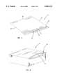
- FIG. 1is a perspective view of a flexible, resealable package according to an example embodiment of the present invention
- FIG. 2is a perspective view of a rigid, resealable package also according to an example embodiment of the present invention
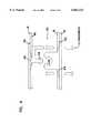
- FIG. 3is a fragmented, cross-sectional, somewhat schematic view of a resealable closure mechanism, according to a first example embodiment of the present invention
- FIG. 4is a fragmented, cross-sectional, somewhat schematic view of a resealable closure mechanism, according to a second example embodiment of the present invention.
- FIG. 5is a fragmented, cross-sectional, somewhat schematic view of a resealable closure mechanism according to a third example embodiment of the present invention.
- FIG. 6is a fragmented, cross-sectional, somewhat schematic view of a resealable closure mechanism, according to a fourth example embodiment of the present invention.
- the present inventionis believed to be applicable to a variety of packaging arrangements.
- the inventionhas been found to be particularly advantageous for manufacturing resealable closure mechanisms.
- An appreciation of various aspects of the inventionis best gained through a discussion of an application example for such a packaging arrangement.
- an interlocking closure memberis extruded separate from its respective base strip.
- FIGS. 1 and 2illustrate example types of packages 17, 24 that benefit from use of such resealable closure mechanisms.
- FIG. 1illustrates an example packaging arrangement in the form of a resealable, flexible package 17 having a zipper-type closure mechanism 26 constructed in accordance with the present invention.
- the flexible package 17includes first and second opposed panel sections 15, 16 made from a flexible, polymeric film.
- the first and second panel sections 15, 16are heat-sealed together along two edges 25, 27 and meet at a fold line in order to form a three-edged containment section for a product within the interior of the package 17.
- the fold linecomprises the bottom edge 29.
- two separate panel sections 15, 16 of polymeric filmmay be used and heat-sealed together along the two edges 25, 27 and at the bottom 29.
- Accessis provided to the interior of the package 17 through a mouth 31.
- the package 17includes tear strings and/or notches at the mouth 31 to assist with opening the package 17.
- FIG. 2is a perspective view depicting a rigid resealable package 24.
- the rigid resealable package 24has the same basic features as the flexible resealable package 17 of FIG. 1.
- the package 24, however,has only one flexible top side 21. The remaining five sides are rigid.
- a resealable closure mechanism 26is illustrated in FIG. 1 at the opening of the flexible package 17.
- a similar closure mechanism 26'is illustrated in FIG. 2.
- Each closure mechanism 26 or 26'extends the width of the package 17 or 24.
- Each closure mechanism 26 or 26'can be one of a variety of closure mechanisms.
- the resealable closure mechanism 26 of FIG. 1is shown in the specific form of a zipper-type mechanism.
- the resealable closure mechanism 26includes an elongated male closure profile 28 and an elongated female closure profile 30.
- the male closure profile 28is comprised of a base strip 42 and an interlocking closure member 44.
- the base strip 42is attached to the first package film 15.
- the female closure profile 30is likewise comprised of a base strip 51 and an interlocking closure member 53.
- the base strip 51is attached to the second package film 16.
- a resealable closure mechanismsuch as this is described in U.S. Pat. No. 5,486,051, hereby incorporated by reference.
- the male and female closure profiles 28, 30are extruded separately from the base strips 42, 51.
- the male closure profile 28is manufactured by extruding the interlocking closure member 44 through a die plate by an extruder.
- This extrudercarries the molten material for forming the interlocking closure member 44.
- the die plateincludes input ports, output ports, and channels connecting these input ports to output ports.
- the extruderfeeds the molten material to different input ports, and the channels are designed to configure the molten material into the shape of the interlocking closure member 44.
- An extrusion processsuch as this is described in U.S. Pat. No. 5,411,692, hereby incorporated by reference.
- the female closure profile 30is manufactured by extruding the interlocking closure member 53 through a die plate by an extruder.
- This extrudercarries the molten material for forming the interlocking closure member 53.
- the extruderfeeds the molten material to different input ports, and the channels are designed to configure the molten material into the shape of the interlocking closure member 53.
- the closure members 44, 53are interlocked.
- the base strips 42, 51are separately extruded through die plates by extruders. These extruders carry the molten materials for forming the base strips 42, 51. The extruders feed the molten materials to different input ports, and the channels are designed to configure the molten materials into the shapes of the base strips 41, 51.
- the base strips 42, 51are attached to the interlocking closure members 44, 53, respectively, at a later time using one of a variety of methods.
- the base strips 42, 51can be attached to the closure members 44, 53, respectively, immediately after extrusion, using the heat of extrusion to bond the base strips 42, 51 to the closure members 44, 53.
- an adhesivesuch as a strip of tape or glue, could be used to adhere the base strips 42, 51 to the closure members 44, 53, respectively.
- the interlocking closure members 44, 53are extruded, interlocked, and coiled onto a spool for storage and later use.
- the base strips 42, 51are also extruded and coiled onto a spool for storage and later use.
- the interlocking closure members 44, 53 and the base strips 42, 51are extruded, interlocked, and attached to one another in the manufacturing line.
- the closure profiles 28, 30are extruded from a polymeric resin such as polyethylene. Because the interlocking closure members 44, 53 and the base strips 42, 51 are extruded separately, the closure members 44, 53 can be extruded from one material while the base strips 42, 51 are extruded from another material. For example, the interlocking closure members 44, 53 are extruded from polypropylene, and the base strips 42, 51 are extruded from polyethylene.
- This processis advantageous because it allows the interlocking closure members 44, 53 to be extruded from a material that best retains the shape of the closure members 44, 53 and facilitates the engagement of the interlocking closure members 44, 53, while also allowing the base strips 42, 51 to be extruded from a material that is compatible with the package design.
- the separate extrusion of the interlocking closure members 44, 53 and the respective base strips 42, 51is advantageous because it allows standardization of the interlocking closure members.
- the male and female interlocking closure members 44, 53 illustrated in FIG. 3may be used for all package applications.
- the respective base strips 42, 51are varied in composition and design according to package type and use. Different packages require different base strip designs.
- the manufactureravoids redesigning the interlocking closure members 44, 53 whenever the respective base strips 42, 51 are redesigned. This process is also advantageous because it allows for easy storage of the profiles for out-of-line extrusions.
- the female interlocking closure member 53has a triangular-shaped base 54
- the male interlocking closure member 44has a triangular-shaped base 45.
- the triangular bases 45, 54support the interlocking closure members 44, 53, respectively.
- the bases 45, 54help to maintain the closure members 44, 53 perpendicular to the base strips 42, 51, respectively. This support makes the closure mechanism 26 stronger and more effective.
- the bases 45, 54also provide a thickened area that acts as a heat sink, protecting the closure members 44, 53 from distortion when the closure profiles 28, 30 are heat-sealed to the package films 15, 16.
- an ultrasonic sealis used to attach the interlocking closure member 53 to its base strip 51.
- ultrasonicsare used to bond the interlocking closure member 53 to the base strip 51.
- the same processis used to bond the male interlocking closure member 44 to its base strip 42.
- a molten polymeric materialcan be used.
- the bases 45, 54allow the interlocking closure members 44, 53 to be attached to the base strips 42, 51, respectively, with a molten polymeric material that is laid between the interlocking closure members 44, 53 and the base strips 42, 51, respectively.
- An example of such a polymeric materialis polyethylene.
- An adhesive layer 46 or 55is coextruded with the interlocking closure members 44, 53, respectively.
- the closure members 44, 53are extruded through a die plate by an extruder.
- the adhesive layers 46, 55are extruded through the die plate by a different extruder carrying molten adhesive material for forming the adhesive layers 46, 55.
- the adhesive layers 46, 55are bonded to the closure members 44, 53.
- the adhesive layers 46, 55facilitate bonding between the closure members 44, 53 and the base strips 42, 51, respectively.
- an adhesive layer 43 or 52is coextruded with the base strips 42, 51 to further facilitate the bonding between the closure members 44, 53 and the base strips 42, 51, respectively.
- the adhesive layerscomprise an adhesive such as ethylene vinyl acetate, ethylene acrylic acid, a polymer rubber blend, and the like. These materials bond at a temperature between 125 degrees Fahrenheit to 260 degrees Fahrenheit. This temperature is sufficiently less than the melting point of the closure members 44, 53.
- the adhesive layers 46, 55, 43, and 52are heated to between 125 degrees Fahrenheit to 260 degrees Fahrenheit. This bonds the base strips 42, 51 to the closure members 44, 53, respectively, without distorting the closure members 44, 53.
- the adhesivemay be a "cold seal” adhesive that is activated by applying force. Adhesive can be applied to both surfaces by gravure or flexographic methods. Both surfaces are “dry” to the touch, but bond when pressed together.
- closure profiles 28, 30Prior to initially opening a package incorporating the closure arrangements shown in FIGS. 3, 4, 5, or 6, the closure profiles 28, 30 are interlocked with each other. To open the package 17, the interlocked closure profiles 28, 30 are detached from each other by grabbing onto the first and second films 15, 16 and pulling them apart.
Landscapes
- Engineering & Computer Science (AREA)
- Mechanical Engineering (AREA)
- Bag Frames (AREA)
- Extrusion Moulding Of Plastics Or The Like (AREA)
- Making Paper Articles (AREA)
Abstract
Description
Claims (11)
Priority Applications (4)
| Application Number | Priority Date | Filing Date | Title |
|---|---|---|---|
| US09/083,555US6063224A (en) | 1998-05-22 | 1998-05-22 | Method for separate closure extrusion |
| DE69905215TDE69905215T2 (en) | 1998-05-22 | 1999-05-21 | Process for separate extrusion of closure elements |
| EP99303956AEP0958909B1 (en) | 1998-05-22 | 1999-05-21 | Method for separate closure member extrusion |
| JP11142990AJP2000153560A (en) | 1998-05-22 | 1999-05-24 | Method for extruding closures separately |
Applications Claiming Priority (1)
| Application Number | Priority Date | Filing Date | Title |
|---|---|---|---|
| US09/083,555US6063224A (en) | 1998-05-22 | 1998-05-22 | Method for separate closure extrusion |
Publications (1)
| Publication Number | Publication Date |
|---|---|
| US6063224Atrue US6063224A (en) | 2000-05-16 |
Family
ID=22179095
Family Applications (1)
| Application Number | Title | Priority Date | Filing Date |
|---|---|---|---|
| US09/083,555Expired - Fee RelatedUS6063224A (en) | 1998-05-22 | 1998-05-22 | Method for separate closure extrusion |
Country Status (4)
| Country | Link |
|---|---|
| US (1) | US6063224A (en) |
| EP (1) | EP0958909B1 (en) |
| JP (1) | JP2000153560A (en) |
| DE (1) | DE69905215T2 (en) |
Cited By (10)
| Publication number | Priority date | Publication date | Assignee | Title |
|---|---|---|---|---|
| US6372068B1 (en)* | 1999-09-21 | 2002-04-16 | Roger S. Kincel | Composite polymeric twist tie |
| US20040130050A1 (en)* | 2003-01-07 | 2004-07-08 | Wright Donald K. | Vibratory molding process and product |
| US20040204303A1 (en)* | 1999-10-12 | 2004-10-14 | Com-Pac International, Inc. | Reclosable fastener profile seal and method of forming a fastener profile assembly |
| US20050247756A1 (en)* | 2004-03-31 | 2005-11-10 | Frazer James T | Connection mechanism and method |
| US20060196019A1 (en)* | 1999-10-12 | 2006-09-07 | Com-Pac International, Inc. | Vibratory molding process and product |
| US20060201626A1 (en)* | 1999-10-12 | 2006-09-14 | Wright Donald K | Method of sealing reclosable fasteners |
| US20070086682A1 (en)* | 1999-10-12 | 2007-04-19 | Com-Pac International, Inc. | Airtight reclosable fastener |
| US20080105380A1 (en)* | 2000-12-08 | 2008-05-08 | Toyota Motor Sales, U.S.A., Inc. | System for molding composite structures |
| US20090035412A1 (en)* | 2007-07-31 | 2009-02-05 | Sobcinski Thomas J | Hybrid lay-up tool |
| US20230128908A1 (en)* | 2021-10-26 | 2023-04-27 | Illinois Tool Works Inc. | Reclosable bag having a repulpable zipper |
Families Citing this family (8)
| Publication number | Priority date | Publication date | Assignee | Title |
|---|---|---|---|---|
| DE10214337A1 (en)* | 2002-03-28 | 2003-10-16 | Kreye Bernhard | Method of making a clip-on mounting assembly |
| CN102209620B (en) | 2008-10-10 | 2014-06-25 | 丹尼尔·皮 | Co-extrusion blow molding apparatus and method and airtight device |
| US9371153B1 (en) | 2015-03-04 | 2016-06-21 | Modern Twist, Inc. | Shaped elastomeric container with integrated leak resistant seal |
| USD903483S1 (en) | 2018-11-16 | 2020-12-01 | Stasher, Inc. | Sealable container |
| US10407217B1 (en) | 2018-11-16 | 2019-09-10 | Stasher, Inc. | Method of manufacturing a container with a leak resistant seal |
| US10625906B1 (en) | 2018-11-16 | 2020-04-21 | Stasher, Inc. | Inside out method of manufacturing a container with a leak resistant seal |
| US11124330B2 (en) | 2020-02-06 | 2021-09-21 | Stasher, Inc. | Shaped elastomeric container with integrated leak resistant seal and pressure shield |
| US11873143B2 (en) | 2020-02-06 | 2024-01-16 | Stasher, Inc. | Shaped elastomeric container with integrated leak resistant seal and pressure shield |
Citations (33)
| Publication number | Priority date | Publication date | Assignee | Title |
|---|---|---|---|---|
| US3462332A (en)* | 1965-03-05 | 1969-08-19 | High Polymer Chem Ind Ltd | Method of continuously providing a fastener on a thermoplastic film |
| US3904468A (en)* | 1971-09-07 | 1975-09-09 | Minigrip Inc | Method of making a flexible closure |
| US3948705A (en)* | 1972-07-25 | 1976-04-06 | Steven Ausnit | Method for making multiple plastic bags with reclosable fasteners thereon |
| US4191230A (en)* | 1978-02-16 | 1980-03-04 | Minigrip, Inc. | Integral extruded construction for bags |
| US4295919A (en)* | 1978-12-15 | 1981-10-20 | The Dow Chemical Co. | Forming an integral closure for a thermoplastic container |
| US4341575A (en)* | 1975-11-03 | 1982-07-27 | Minigrip, Inc. | Means for joining flexible fastener strips to film |
| US4428788A (en)* | 1982-05-14 | 1984-01-31 | Union Carbide Corporation | Film-tape-closure device slot cast integrated interlocking structure and extrusion method |
| US4601694A (en)* | 1982-04-16 | 1986-07-22 | Minigrip, Inc. | Thin wall reclosable bag material and method of making same |
| US4615045A (en)* | 1983-11-02 | 1986-09-30 | Minigrip, Inc. | Pilfer proof hangup bag structure and method |
| US4618383A (en)* | 1984-06-22 | 1986-10-21 | Mobil Oil Corporation | Method and apparatus for the manufacture of plastic bags having interlocking profile extrusions |
| US4673383A (en)* | 1985-11-12 | 1987-06-16 | Minigrip, Incorporated | Fusible rib bonding of fasteners to substrate |
| US4676851A (en)* | 1984-04-25 | 1987-06-30 | First Brands Corporation | Process and apparatus for forming integral interlocking closure film stock |
| US4691372A (en)* | 1986-08-05 | 1987-09-01 | Minigrip, Inc. | Manufacture of multi-layered reclosable bag making material and bags made therefrom |
| US4701358A (en)* | 1984-03-21 | 1987-10-20 | The Dow Chemical Company | Thermoplastic film with integral closures and reclosable container formed therefrom |
| US4712684A (en)* | 1985-08-05 | 1987-12-15 | Minigrip, Inc. | Bag dispensing arrangement |
| US4731911A (en)* | 1986-08-08 | 1988-03-22 | Minigrip, Inc. | Extruded closure strip carrying reactivatable adhesive layer |
| US4755248A (en)* | 1986-12-30 | 1988-07-05 | The Dow Chemical Company | Slot-cast intergrated interlocking film closure structure |
| US4756629A (en)* | 1987-04-23 | 1988-07-12 | Minigrip, Inc. | System for producing non-compatible zipper film |
| US4787755A (en)* | 1985-11-08 | 1988-11-29 | Kcl Corporation | Reclosable flexible container having fastener profiles sealed at their ends to the outside of the bag |
| US4854017A (en)* | 1986-07-22 | 1989-08-08 | First Brands Corporation | Multiposition interlocking closure fastening device |
| US4929487A (en)* | 1987-09-14 | 1990-05-29 | Minigrip, Inc. | Bag making material having fastener profiles and alignment ribs with reinforcing and stabilizing beam effect ridge means |
| US5012561A (en)* | 1990-05-18 | 1991-05-07 | The Dow Chemical Company | Closure for reclosable thermoplastic containers |
| US5053091A (en)* | 1990-01-18 | 1991-10-01 | Packaging Innovations, Inc. | Method and apparatus for manufacturing plastic film with integral interlocking closure members incorporating shape conforming cooling shoes after extrusion |
| US5071689A (en)* | 1990-01-08 | 1991-12-10 | Zip-Pak Incorporated | Hinged zipper |
| US5103546A (en)* | 1990-11-09 | 1992-04-14 | Minnesota Mining And Manufacturing Company | Process for preparing a strip of flexible closure material to be applied to a receptacle |
| EP0484599A1 (en)* | 1990-11-08 | 1992-05-13 | Fujitokushu Shigyo Company Limited | Closure for a bag |
| US5188461A (en)* | 1988-10-17 | 1993-02-23 | Schurpack, Inc. | Packing, method of manufacturing same, and strip material therefor |
| US5242516A (en)* | 1990-10-22 | 1993-09-07 | Reynolds Consumer Products Inc. | Co-extruded profile strip containing lateral webs with adhesive subdivided into ribs |
| US5382094A (en)* | 1992-05-08 | 1995-01-17 | Minigrip, Inc. | Reclosable plastic bag with oscillating grip strip |
| US5573614A (en)* | 1993-12-28 | 1996-11-12 | Minigrip, Inc. | Method for stabilizing a plastic zipper during attachment to a film |
| GB2311274A (en)* | 1996-03-20 | 1997-09-24 | Roeder Ind Holdings | Reclosable fasteners for plastic bags |
| EP0814026A2 (en)* | 1996-06-17 | 1997-12-29 | Idemitsu Petrochemical Co., Ltd. | Snap zipper and a bag with the same |
| EP0908294A2 (en)* | 1997-10-06 | 1999-04-14 | Illinois Tool Works Inc. | Zipper component |
- 1998
- 1998-05-22USUS09/083,555patent/US6063224A/ennot_activeExpired - Fee Related
- 1999
- 1999-05-21DEDE69905215Tpatent/DE69905215T2/ennot_activeExpired - Fee Related
- 1999-05-21EPEP99303956Apatent/EP0958909B1/ennot_activeExpired - Lifetime
- 1999-05-24JPJP11142990Apatent/JP2000153560A/enactivePending
Patent Citations (33)
| Publication number | Priority date | Publication date | Assignee | Title |
|---|---|---|---|---|
| US3462332A (en)* | 1965-03-05 | 1969-08-19 | High Polymer Chem Ind Ltd | Method of continuously providing a fastener on a thermoplastic film |
| US3904468A (en)* | 1971-09-07 | 1975-09-09 | Minigrip Inc | Method of making a flexible closure |
| US3948705A (en)* | 1972-07-25 | 1976-04-06 | Steven Ausnit | Method for making multiple plastic bags with reclosable fasteners thereon |
| US4341575A (en)* | 1975-11-03 | 1982-07-27 | Minigrip, Inc. | Means for joining flexible fastener strips to film |
| US4191230A (en)* | 1978-02-16 | 1980-03-04 | Minigrip, Inc. | Integral extruded construction for bags |
| US4295919A (en)* | 1978-12-15 | 1981-10-20 | The Dow Chemical Co. | Forming an integral closure for a thermoplastic container |
| US4601694A (en)* | 1982-04-16 | 1986-07-22 | Minigrip, Inc. | Thin wall reclosable bag material and method of making same |
| US4428788A (en)* | 1982-05-14 | 1984-01-31 | Union Carbide Corporation | Film-tape-closure device slot cast integrated interlocking structure and extrusion method |
| US4615045A (en)* | 1983-11-02 | 1986-09-30 | Minigrip, Inc. | Pilfer proof hangup bag structure and method |
| US4701358A (en)* | 1984-03-21 | 1987-10-20 | The Dow Chemical Company | Thermoplastic film with integral closures and reclosable container formed therefrom |
| US4676851A (en)* | 1984-04-25 | 1987-06-30 | First Brands Corporation | Process and apparatus for forming integral interlocking closure film stock |
| US4618383A (en)* | 1984-06-22 | 1986-10-21 | Mobil Oil Corporation | Method and apparatus for the manufacture of plastic bags having interlocking profile extrusions |
| US4712684A (en)* | 1985-08-05 | 1987-12-15 | Minigrip, Inc. | Bag dispensing arrangement |
| US4787755A (en)* | 1985-11-08 | 1988-11-29 | Kcl Corporation | Reclosable flexible container having fastener profiles sealed at their ends to the outside of the bag |
| US4673383A (en)* | 1985-11-12 | 1987-06-16 | Minigrip, Incorporated | Fusible rib bonding of fasteners to substrate |
| US4854017A (en)* | 1986-07-22 | 1989-08-08 | First Brands Corporation | Multiposition interlocking closure fastening device |
| US4691372A (en)* | 1986-08-05 | 1987-09-01 | Minigrip, Inc. | Manufacture of multi-layered reclosable bag making material and bags made therefrom |
| US4731911A (en)* | 1986-08-08 | 1988-03-22 | Minigrip, Inc. | Extruded closure strip carrying reactivatable adhesive layer |
| US4755248A (en)* | 1986-12-30 | 1988-07-05 | The Dow Chemical Company | Slot-cast intergrated interlocking film closure structure |
| US4756629A (en)* | 1987-04-23 | 1988-07-12 | Minigrip, Inc. | System for producing non-compatible zipper film |
| US4929487A (en)* | 1987-09-14 | 1990-05-29 | Minigrip, Inc. | Bag making material having fastener profiles and alignment ribs with reinforcing and stabilizing beam effect ridge means |
| US5188461A (en)* | 1988-10-17 | 1993-02-23 | Schurpack, Inc. | Packing, method of manufacturing same, and strip material therefor |
| US5071689A (en)* | 1990-01-08 | 1991-12-10 | Zip-Pak Incorporated | Hinged zipper |
| US5053091A (en)* | 1990-01-18 | 1991-10-01 | Packaging Innovations, Inc. | Method and apparatus for manufacturing plastic film with integral interlocking closure members incorporating shape conforming cooling shoes after extrusion |
| US5012561A (en)* | 1990-05-18 | 1991-05-07 | The Dow Chemical Company | Closure for reclosable thermoplastic containers |
| US5242516A (en)* | 1990-10-22 | 1993-09-07 | Reynolds Consumer Products Inc. | Co-extruded profile strip containing lateral webs with adhesive subdivided into ribs |
| EP0484599A1 (en)* | 1990-11-08 | 1992-05-13 | Fujitokushu Shigyo Company Limited | Closure for a bag |
| US5103546A (en)* | 1990-11-09 | 1992-04-14 | Minnesota Mining And Manufacturing Company | Process for preparing a strip of flexible closure material to be applied to a receptacle |
| US5382094A (en)* | 1992-05-08 | 1995-01-17 | Minigrip, Inc. | Reclosable plastic bag with oscillating grip strip |
| US5573614A (en)* | 1993-12-28 | 1996-11-12 | Minigrip, Inc. | Method for stabilizing a plastic zipper during attachment to a film |
| GB2311274A (en)* | 1996-03-20 | 1997-09-24 | Roeder Ind Holdings | Reclosable fasteners for plastic bags |
| EP0814026A2 (en)* | 1996-06-17 | 1997-12-29 | Idemitsu Petrochemical Co., Ltd. | Snap zipper and a bag with the same |
| EP0908294A2 (en)* | 1997-10-06 | 1999-04-14 | Illinois Tool Works Inc. | Zipper component |
Cited By (15)
| Publication number | Priority date | Publication date | Assignee | Title |
|---|---|---|---|---|
| US6372068B1 (en)* | 1999-09-21 | 2002-04-16 | Roger S. Kincel | Composite polymeric twist tie |
| US7337507B2 (en) | 1999-10-12 | 2008-03-04 | Com-Pac International | Zipper tape having a reclosable portion and a planar portion |
| US8506745B2 (en) | 1999-10-12 | 2013-08-13 | Donald K. Wright | Method of sealing reclosable fasteners |
| US20040204303A1 (en)* | 1999-10-12 | 2004-10-14 | Com-Pac International, Inc. | Reclosable fastener profile seal and method of forming a fastener profile assembly |
| US8002467B2 (en) | 1999-10-12 | 2011-08-23 | Com-Pac International, Inc. | Reclosable fastener profile seal and method of forming a fastener profile assembly |
| US20060196019A1 (en)* | 1999-10-12 | 2006-09-07 | Com-Pac International, Inc. | Vibratory molding process and product |
| US20060201626A1 (en)* | 1999-10-12 | 2006-09-14 | Wright Donald K | Method of sealing reclosable fasteners |
| US20070086682A1 (en)* | 1999-10-12 | 2007-04-19 | Com-Pac International, Inc. | Airtight reclosable fastener |
| US20080105380A1 (en)* | 2000-12-08 | 2008-05-08 | Toyota Motor Sales, U.S.A., Inc. | System for molding composite structures |
| US7074359B2 (en)* | 2003-01-07 | 2006-07-11 | Com-Pac International | Vibratory molding process and product |
| US20040130050A1 (en)* | 2003-01-07 | 2004-07-08 | Wright Donald K. | Vibratory molding process and product |
| US20050247756A1 (en)* | 2004-03-31 | 2005-11-10 | Frazer James T | Connection mechanism and method |
| US20090035412A1 (en)* | 2007-07-31 | 2009-02-05 | Sobcinski Thomas J | Hybrid lay-up tool |
| US20230128908A1 (en)* | 2021-10-26 | 2023-04-27 | Illinois Tool Works Inc. | Reclosable bag having a repulpable zipper |
| US12415653B2 (en)* | 2021-10-26 | 2025-09-16 | Illinois Tool Works Inc. | Reclosable bag having a repulpable zipper |
Also Published As
| Publication number | Publication date |
|---|---|
| DE69905215D1 (en) | 2003-03-13 |
| DE69905215T2 (en) | 2003-12-11 |
| EP0958909B1 (en) | 2003-02-05 |
| EP0958909A1 (en) | 1999-11-24 |
| JP2000153560A (en) | 2000-06-06 |
Similar Documents
| Publication | Publication Date | Title |
|---|---|---|
| US6063224A (en) | Method for separate closure extrusion | |
| US5242516A (en) | Co-extruded profile strip containing lateral webs with adhesive subdivided into ribs | |
| US5216787A (en) | Co-extruded profile strip containing lateral webs with adhesive subdivided into ribs | |
| US5983466A (en) | Leakproof resealable slider closure mechanism | |
| US5238306A (en) | Method of producing a sealing system for a reclosable webbed-wall package, and system made | |
| US5988880A (en) | Resealable closure mechanism | |
| EP2055643B1 (en) | Chuck tape with cut tape, its manufacturing method, and packaging bag with chuck tape | |
| US5947603A (en) | Resealable closure mechanism having a slider device and separate housing | |
| US8789247B2 (en) | Interlock tool, bag making use thereof and process for producing them | |
| KR101286914B1 (en) | Chuck tape and packaging bag with chuck tape | |
| US5486051A (en) | Closure arrangement having a breakaway seal | |
| EP0945359A2 (en) | Zip lock bag closure with pealable seal | |
| AU721125B2 (en) | Peel seal zipper tape | |
| EP2103541A1 (en) | Easily tearable fastener tape, method of producing the fastener tape, packaging bag with easily tearable fastener tape, and device and method for producing the packaging bag | |
| US5927855A (en) | Tamper-evident closure arrangements and methods | |
| MXPA06012943A (en) | Flexible package with internal, resealable closure feature. | |
| US6092931A (en) | Closure mechanism with a heat-insulating layer | |
| US6361211B1 (en) | Closure mechanism with a heat-insulating filler | |
| JP3080342B2 (en) | Articulated bag | |
| JP2004268321A (en) | LAMINATE, PROCESS FOR PRODUCING THE SAME, AND RESEALABLE PACKAGE USING THE SAME | |
| JPH0752961A (en) | Engaging jig and packing bag with the same | |
| WO2000010419A1 (en) | Separate closure device for resealable packages |
Legal Events
| Date | Code | Title | Description |
|---|---|---|---|
| AS | Assignment | Owner name:REYNOLDS CONSUMER PRODUCTS, INC., VIRGINIA Free format text:ASSIGNMENT OF ASSIGNORS INTEREST;ASSIGNORS:TOMIC, MLADOMIR;KETTNER, CATHERINE E.;REEL/FRAME:009198/0964 Effective date:19980518 | |
| FEPP | Fee payment procedure | Free format text:PAYOR NUMBER ASSIGNED (ORIGINAL EVENT CODE: ASPN); ENTITY STATUS OF PATENT OWNER: LARGE ENTITY | |
| FPAY | Fee payment | Year of fee payment:4 | |
| FPAY | Fee payment | Year of fee payment:8 | |
| REMI | Maintenance fee reminder mailed | ||
| FEPP | Fee payment procedure | Free format text:PAYER NUMBER DE-ASSIGNED (ORIGINAL EVENT CODE: RMPN); ENTITY STATUS OF PATENT OWNER: LARGE ENTITY Free format text:PAYOR NUMBER ASSIGNED (ORIGINAL EVENT CODE: ASPN); ENTITY STATUS OF PATENT OWNER: LARGE ENTITY | |
| AS | Assignment | Owner name:CREDIT SUISSE, SYDNEY BRANCH, AUSTRALIA Free format text:NOTICE AND CONFIRMATION OF GRANT OF SECURITY INTEREST IN PATENTS;ASSIGNOR:REYNOLDS CONSUMER PRODUCTS, INC.;REEL/FRAME:020828/0496 Effective date:20080229 Owner name:CREDIT SUISSE, SYDNEY BRANCH,AUSTRALIA Free format text:NOTICE AND CONFIRMATION OF GRANT OF SECURITY INTEREST IN PATENTS;ASSIGNOR:REYNOLDS CONSUMER PRODUCTS, INC.;REEL/FRAME:020828/0496 Effective date:20080229 | |
| AS | Assignment | Owner name:REYNOLDS CONSUMER PRODUCTS, INC., VIRGINIA Free format text:TERMINATION AND RELEASE OF SECURITY INTEREST;ASSIGNOR:CREDIT SUISSE, SYDNEY BRANCH;REEL/FRAME:023546/0309 Effective date:20091105 Owner name:REYNOLDS CONSUMER PRODUCTS, INC.,VIRGINIA Free format text:TERMINATION AND RELEASE OF SECURITY INTEREST;ASSIGNOR:CREDIT SUISSE, SYDNEY BRANCH;REEL/FRAME:023546/0309 Effective date:20091105 | |
| AS | Assignment | Owner name:THE BANK OF NEW YORK MELLON, NEW YORK Free format text:SECURITY AGREEMENT;ASSIGNORS:CLOSURE SYSTEMS INTERNATIONAL INC.;REYNOLDS CONSUMER PRODUCTS INC.;REYNOLDS FOIL INC.;AND OTHERS;REEL/FRAME:023574/0312 Effective date:20091105 Owner name:THE BANK OF NEW YORK MELLON,NEW YORK Free format text:SECURITY AGREEMENT;ASSIGNORS:CLOSURE SYSTEMS INTERNATIONAL INC.;REYNOLDS CONSUMER PRODUCTS INC.;REYNOLDS FOIL INC.;AND OTHERS;REEL/FRAME:023574/0312 Effective date:20091105 | |
| REMI | Maintenance fee reminder mailed | ||
| LAPS | Lapse for failure to pay maintenance fees | ||
| STCH | Information on status: patent discontinuation | Free format text:PATENT EXPIRED DUE TO NONPAYMENT OF MAINTENANCE FEES UNDER 37 CFR 1.362 | |
| FP | Lapsed due to failure to pay maintenance fee | Effective date:20120516 | |
| AS | Assignment | Owner name:REYNOLDS CONSUMER PRODUCTS LLC (F/K/A REYNOLDS FOIL INC.), ILLINOIS Free format text:RELEASE OF SECURITY INTEREST IN CERTAIN PATENT COLLATERAL;ASSIGNOR:THE BANK OF NEW YORK MELLON, AS COLLATERAL AGENT;REEL/FRAME:051798/0051 Effective date:20200204 Owner name:REYNOLDS PRESTO PRODUCTS INC. (F/K/A REYNOLDS CONSUMER PRODUCTS, INC.), ILLINOIS Free format text:RELEASE OF SECURITY INTEREST IN CERTAIN PATENT COLLATERAL;ASSIGNOR:THE BANK OF NEW YORK MELLON, AS COLLATERAL AGENT;REEL/FRAME:051798/0051 Effective date:20200204 |