US6063100A - Embolic coil deployment system with improved embolic coil - Google Patents
Embolic coil deployment system with improved embolic coilDownload PDFInfo
- Publication number
- US6063100A US6063100AUS09/256,163US25616399AUS6063100AUS 6063100 AUS6063100 AUS 6063100AUS 25616399 AUS25616399 AUS 25616399AUS 6063100 AUS6063100 AUS 6063100A
- Authority
- US
- United States
- Prior art keywords
- coil
- catheter
- proximal
- section
- deployment system
- Prior art date
- Legal status (The legal status is an assumption and is not a legal conclusion. Google has not performed a legal analysis and makes no representation as to the accuracy of the status listed.)
- Expired - Lifetime
Links
Images

Classifications
- A—HUMAN NECESSITIES
- A61—MEDICAL OR VETERINARY SCIENCE; HYGIENE
- A61B—DIAGNOSIS; SURGERY; IDENTIFICATION
- A61B17/00—Surgical instruments, devices or methods
- A61B17/12—Surgical instruments, devices or methods for ligaturing or otherwise compressing tubular parts of the body, e.g. blood vessels or umbilical cord
- A61B17/12022—Occluding by internal devices, e.g. balloons or releasable wires
- A61B17/12131—Occluding by internal devices, e.g. balloons or releasable wires characterised by the type of occluding device
- A61B17/1214—Coils or wires
- A61B17/12154—Coils or wires having stretch limiting means
- A—HUMAN NECESSITIES
- A61—MEDICAL OR VETERINARY SCIENCE; HYGIENE
- A61B—DIAGNOSIS; SURGERY; IDENTIFICATION
- A61B17/00—Surgical instruments, devices or methods
- A61B2017/00535—Surgical instruments, devices or methods pneumatically or hydraulically operated
- A61B2017/00539—Surgical instruments, devices or methods pneumatically or hydraulically operated hydraulically
- A—HUMAN NECESSITIES
- A61—MEDICAL OR VETERINARY SCIENCE; HYGIENE
- A61B—DIAGNOSIS; SURGERY; IDENTIFICATION
- A61B17/00—Surgical instruments, devices or methods
- A61B17/12—Surgical instruments, devices or methods for ligaturing or otherwise compressing tubular parts of the body, e.g. blood vessels or umbilical cord
- A61B17/12022—Occluding by internal devices, e.g. balloons or releasable wires
- A61B2017/1205—Introduction devices
- A61B2017/12054—Details concerning the detachment of the occluding device from the introduction device
- A61B2017/12068—Details concerning the detachment of the occluding device from the introduction device detachable by heat
- A—HUMAN NECESSITIES
- A61—MEDICAL OR VETERINARY SCIENCE; HYGIENE
- A61B—DIAGNOSIS; SURGERY; IDENTIFICATION
- A61B17/00—Surgical instruments, devices or methods
- A61B17/12—Surgical instruments, devices or methods for ligaturing or otherwise compressing tubular parts of the body, e.g. blood vessels or umbilical cord
- A61B17/12022—Occluding by internal devices, e.g. balloons or releasable wires
- A61B2017/1205—Introduction devices
- A61B2017/12054—Details concerning the detachment of the occluding device from the introduction device
- A61B2017/12081—Details concerning the detachment of the occluding device from the introduction device detachable by inflation
Definitions
- the present inventionrelates to a medical device for placing an embolic coil at a preselected location within a vessel of the human body, and more particularly, relates to a catheter having a distal tip for retaining the embolic coil in order to transport the coil to a preselected position within the vessel and a control mechanism for releasing the embolic coil at the preselected position.
- Coils which are placed in vesselsmay take the form of helically wound coils, or alternatively, may be random wound coils, coils wound within other coils or many other such coil configurations. Examples of various coil configurations are disclosed in U.S. Pat. No. 5,334,210, entitled, “Vascular Occlusion Assembly”; U.S. Pat. No. 5,382,259, entitled, "Vasoocclusion Coil With Attached Tubular Woven Or Braided Fibrous Coverings.” Embolic coils are generally formed of a radiopaque metallic materials, such as platinum, gold, tungsten or alloys of these metals. Often times several coils are placed at a given location in order to occlude the flow of blood through the vessel by promoting thrombus formation at the particular location.
- embolic coilshave been placed within the distal end of the catheter and when the distal end of the catheter is properly positioned the coil may then be pushed out of the end of the catheter with, for example a guidewire, to release the coil at the desired location.
- This procedure of placement of the embolic coilis conducted under fluoroscopic visualization such that the movement of the coil through the vasculature of the body may be monitored and the coil may be placed in the desired location.
- Another coil positioning systemutilizes a catheter having a socket at the distal end of the catheter for retaining a ball which is bonded to the proximal end of the coil.
- the ballwhich is larger in diameter than the outside diameter of the coil, is placed in a socket within the lumen at the distal end of the catheter and the catheter is then moved into a vessel in order to place the coil at a desired position.
- a pusher wire with a piston at the end thereofis pushed distally from the proximal end of the catheter to thereby push the ball out of the socket in order to thereby release the coil at the desired position.
- Another method for placing an embolic coilis that of utilizing a heat releasable adhesive bond for retaining the coil at the distal end of the catheter.
- One such systemuses laser energy which is transmitted through a fiber optic cable in order to apply heat to the adhesive bond in order to release the coil from the end of the catheter.
- Such a methodis disclosed in U.S. Pat. No. 5,108,407, entitled, "Method And Apparatus For Placement Of An Embolic Coil.”
- Such a systemalso suffers from the problem of having a separate element which extends throughout the length of the catheter with the resulting stiffness of the catheter.
- Still another method for placing an embolic coilis disclosed in co-pending U.S. patent application Ser. No. 09/177,848, entitled “Embolic Coil Hydraulic Deployment System,” filed on Oct. 21, 1998 and assigned to the same assignee as the present patent application.
- This patent applicationdiscloses the use of fluid pressure which is applied to the distal tip of the catheter for expanding the lumen in order to release the embolic coil.
- the present inventionis directed toward a vascular occlusive coil deployment system for use in placing an embolic coil at a preselected site within a vessel which includes an elongated, flexible catheter having a distal tip for retaining the coil so that the coil may be moved to the preselected position within the vessel.
- the catheterhas a lumen which extends therethrough the length of the catheter and also includes a distal end which is formed of a material having a durometer such that when a fluid pressure of about 90 to 450 pounds per square inch (psi) is applied to the interior of the catheter, the walls of the distal tip expand outwardly, or radially, to thereby increase the lumen of the distal tip of the catheter.
- the proximal end of the embolic coilis placed into the lumen of the distal tip of the catheter and is retained by the distal tip of the catheter.
- a hydraulic injectorsuch as a syringe, is coupled to the proximal end of the catheter for applying a fluid pressure to the interior of the catheter.
- fluid pressureis then applied to the interior of the catheter by the hydraulic injector to thereby cause the walls of the distal tip to expand outwardly to thereby release the coil for placement in the vessel.
- the proximal portion of the coilis modified in a manner "lock" adjacent coils together to thereby prevent elongation of the proximal portion of the coil.
- Such elongationwill result in the stretching or unwinding of the coil thereby reducing the outside diameter of the coil with the result that the coil could be prematurely released from the distal tip of the deployment system.
- the embolic coiltakes the form of a tightly wound helical coil having a distal end, a proximal end and a lumen extending therethrough also includes a seal plug disposed in fluid tight engagement within the coil lumen at the proximal end of the coil. At the proximal portion of the coil several turns of the coil are spot welded to adjacent turns to thereby prevent elongation of this proximal portion of the coil.
- the series of spot welded points between adjacent coilsforms a straight line which is parallel to the longitudinal axis of the coil.
- the series of spot welded pointsform two straight lines both of which are parallel to the longitudinal axis of the coil.
- the proximal portion of the coil having turns of the coil spot welded to adjacent turnsis of a length in a range of about 0.5 to 4 millimeters and the entire length of the coil is in a range of about 1.5 to 30 centimeters.
- the length of the proximal portion of the coil having turns which are spot welded to adjacent turnsis of a length of about 2.5 millimeters or about 1 percent of the length of the coil.
- the flexible catheteris comprised of a proximal section and a relatively short distal section.
- the proximal sectionis formed of a material which is sufficiently flexible to be passed through the vasculature of the human body and is of a durometer which essentially resists outward expansion when a fluid pressure on the order of about 90 to 450 psi is applied to the interior of the catheter.
- the distal section of the catheteris formed of a material which is also sufficiently flexible to be passed through the vasculature of the body, yet is of a durometer which is significantly lower than the durometer of the proximal section and exhibits the property of expanding outwardly, or radially, when such a fluid pressure is applied to the interior of the catheter to thereby permit the release of the embolic coil.
- the distal section of the catheterhas a durometer in a range of between about 25D and 55D.
- the embolic coilis comprised of a helical coil having a proximal end, a distal end, and a lumen extending therethrough.
- a seal plugis disposed within the lumen of the proximal end of the coil in fluid-tight engagement.
- the proximal end of the coilis disposed in a fluid-tight engagement within the lumen of the distal section of the catheter and is retained by the lumen of the catheter for subsequent release.
- the hydraulic injector for applying a fluid pressure to the interior of the cathetertakes the form of a syringe which is coupled to the proximal end of the catheter for, upon movement of the piston, creating a fluid pressure which is applied to the interior of the catheter to thereby cause the release of the embolic coil.
- the embolic coilmay take the form of other types of implantable devices, such as a vascular filter.
- a method for placing an embolic coil with a selected site within a vessel of the bodycomprising the steps of advancing a catheter through the vasculature of the body to place an embolic coil which is retained within the lumen of the distal tip of the catheter to a preselected site, applying a fluid pressure to the interior of the catheter to thereby cause the distal tip of the catheter to expand radially outwardly to release the embolic coil at the preselected site, and withdrawing the catheter from the vasculature system.
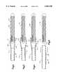
- FIG. 1is an enlarged, partially sectioned view of the hydraulic vascular occlusive coil deployment system
- FIG. 2is an enlarged partially sectional view showing the distal end of the coil deployment system prior to deployment of the coil including an embolic coil of the present invention having turns in the proximal portion of the coil spot welded to adjacent turns along a helical curve;
- FIG. 3 and 4illustrate the sequential steps in the radial expansion of the distal tip of the coil deployment system as the embolic coil is released;
- FIG. 5illustrates the distal tip of the coil deployment system after release of the embolic coil
- FIG. 6is a plan view of an embolic coil having turns in the proximal portion of the coil spot welded to adjacent turns along straight lines;
- an embolic coilhaving coils in the proximal portion of the coil spot welded to adjacent coils along a helical line.
- FIG. 1generally illustrates the vascular occlusive coil deployment system 100 which is comprised of a hydraulic injector or syringe 102, coupled to the proximal end of a catheter 104.
- An embolic coil 106is disposed within the lumen of the distal end 108 of the catheter.
- the proximal end of the coil 106is tightly held within the lumen of the distal section 108 of the catheter 104 until the deployment system is activated for release of the coil.
- the syringe 102includes a threaded piston 110 which is controlled by a handle 112 for infusing fluid into the interior of the catheter 104.
- the catheter 104includes a winged hub 114 which aids in the insertion of the catheter into the vascular system of the body.
- FIG. 2illustrates in more detail the distal end of the catheter 104.
- the catheter 104includes a proximal section 116 and the distal section 108.
- the proximal section 118 of the embolic coil 106is disposed within the distal section 108 of the catheter and is tightly held within the lumen 120 of this distal section 108 prior to release of the coil.
- FIG. 2illustrates the vascular occlusive coil deployment system prior to activation of the piston of the syringe and prior to release of the coil.
- the embolic coil 106may take various forms and configurations and may even take the form of a randomly wound coil, however, with the helical wound coil as illustrated in FIG. 2, the coil is provided with a weld bead or seal plug 122 which is disposed in a lumen 123 which lumen extends throughout the length of the coil 106.
- the seal plug 122serves to prevent the flow of fluid through the lumen of the coil 106 so that when the coil 106 is placed in fluid-tight engagement with the lumen 120 the coil serves to provide a fluid-tight seal at the distal end of the catheter 104.
- Adjacent turns of the coil 106 at the proximal end 118 of the coilare preferably continuously welded together so that the welded turns of the coil in conjunction with the plug seal 122 provide a generally unitary structure with the coil being very flexible with the proximal end of the coil being stretch resistant.
- the plug seal 122serves to plug or seal the distal end of the catheter in a fluid tight relationship.
- the proximal section 116 and the distal section 108 of the catheter 104are formed of materials having different durometers.
- the proximal section 116is preferably formed of Pebax material having a durometer in a range of about 62D to 75D.
- the proximal sectionis sufficiently flexible to transverse the vasculature of the human body, but is sufficiently rigid such that when a fluid pressure of approximately 90 to 450 psi is applied to the interior of this section of the catheter there is very little, if any, radial expansion of the walls of this section.
- the distal section 108 of the catheteris preferably formed of polymer material with a relatively low durometer which, exhibits the characteristic that when a fluid pressure of approximately 90 to 450 psi is applied to the interior of the catheter the walls of the distal section 108 expand radially, somewhat similar to the action of a balloon inflating, to thereby release the proximal end 118 of the coil 106.
- the distal section 108is preferably formed from a block copolymer such as Pebax having a durometer of between 25D and 55D with a durometer of 40D being the preferred durometer.
- FIGS. 3 and 4generally illustrate the coil release mechanism in action for the vascular occlusive catheter deployment system. More particularly, as shown in FIG. 3, when a hydraulic pressure is applied to the interior 124 of the catheter 104 the relatively low durometer distal section 108 of the catheter begins to expand radially, much as a balloon expands during the process of inflation. As the distal section 108 continues to expand radially there comes a point as illustrated in FIG. 4 in which the coil 106 becomes disengaged from the lumen of the distal section 108 and the coil is then released from the catheter and is deployed at that location within the vessel.
- the cathetermay then be withdrawn leaving the coil positioned at the desired site.
- the vaso-occlusion or embolic coil 106is formed by winding a platinum alloy wire into a tightly wound helical configuration.
- the diameter of the wireis generally in the range of about 0.0015 to 0.008 inches.
- the outside diameter of the coil 106is preferably in the range of about 0.006 to 0.055 inches. While the particular embolic coil 106 illustrated in FIG. 6 and 7 is shown as being a straight coil it should be appreciated that embolic coils take the form of various configurations and may for example, take the form of a helix, a random shape configuration or even a coil within a coil configuration.
- the proximal end of the embolic coilis retained or held by the distal tip of the coil deployment system as the coil is moved into a target position. Often times it is necessary to move the coil to a certain position within the vasculature and then to withdraw the coil back to a more proximal position within the vasculature. During the movement of the coil through the vasculature, particularly when the coil is withdrawn, it is possible to stretch or unwind the turns of the coil. If the turns of the coil which are held or restrained by the distal tip of the deployment catheter or stretched or unwound the result is that the outside diameter of the coil in this area decreases. With a decrease in the outside diameter of the coil in the proximal portion of the coil it is possible for the coil to be prematurely released from the deployment system.
- adjacent turns of the proximal portion of the coilare spot welded together in order to prevent separation of these turns with the result in stretching of the coil.
- the length of the embolic coilis about 1.5 to about 30 centimeters and the length of the proximal portion of the coil having adjacent coils spot welded is preferably in a range of about 0.5 to 4 millimeters. In a preferred embodiment, the length of the proximal portion of the coil having adjacent turns welded together is about 2.5 millimeters.
- the line of points formed by spot welding of adjacent coilsforms a single line which extends generally parallel to the longitudinal axis of the coil, but the weld points may extend along two parallel lines which extend generally parallel to the longitudinal axis of the embolic coil as illustrated in FIG. 5.
- the spot welding pointsmay be arranged to form a generally helical configuration on the outside surface of the coil with respect to the longitudinal axis of the coil as illustrated in FIG. 6.
- a liquid silicon material(not shown) may be injected to fill the lumen of the proximal portion of the coil.
- the silicone materialis then allowed to cure in order to further seal the proximal end of the coil to prevent fluid leakage through the turns of the coil.
- the adjacent turnsmay be bonded by various other means such as, for example, by glueing or being attached by wrapping with thread.
- the embolic coilis prevented from stretching over the proximal portion of the coil, however, the coil remains very flexible as is required for proper placement of an embolic coil.
- the cathetermay be activated by applying a hydraulic pressure to the interior of the catheter to thereby cause the catheter to release the coil and deposit the coil very accurately at the desired location.
Landscapes
- Health & Medical Sciences (AREA)
- Surgery (AREA)
- Life Sciences & Earth Sciences (AREA)
- Heart & Thoracic Surgery (AREA)
- Nuclear Medicine, Radiotherapy & Molecular Imaging (AREA)
- Vascular Medicine (AREA)
- Engineering & Computer Science (AREA)
- Biomedical Technology (AREA)
- Reproductive Health (AREA)
- Medical Informatics (AREA)
- Molecular Biology (AREA)
- Animal Behavior & Ethology (AREA)
- General Health & Medical Sciences (AREA)
- Public Health (AREA)
- Veterinary Medicine (AREA)
- Surgical Instruments (AREA)
Abstract
Description
Claims (17)
Priority Applications (1)
| Application Number | Priority Date | Filing Date | Title |
|---|---|---|---|
| US09/256,163US6063100A (en) | 1998-03-10 | 1999-02-22 | Embolic coil deployment system with improved embolic coil |
Applications Claiming Priority (2)
| Application Number | Priority Date | Filing Date | Title |
|---|---|---|---|
| US7738798P | 1998-03-10 | 1998-03-10 | |
| US09/256,163US6063100A (en) | 1998-03-10 | 1999-02-22 | Embolic coil deployment system with improved embolic coil |
Publications (1)
| Publication Number | Publication Date |
|---|---|
| US6063100Atrue US6063100A (en) | 2000-05-16 |
Family
ID=22137764
Family Applications (1)
| Application Number | Title | Priority Date | Filing Date |
|---|---|---|---|
| US09/256,163Expired - LifetimeUS6063100A (en) | 1998-03-10 | 1999-02-22 | Embolic coil deployment system with improved embolic coil |
Country Status (3)
| Country | Link |
|---|---|
| US (1) | US6063100A (en) |
| EP (1) | EP0941702B1 (en) |
| DE (1) | DE69931207T2 (en) |
Cited By (105)
| Publication number | Priority date | Publication date | Assignee | Title |
|---|---|---|---|---|
| US6179857B1 (en)* | 1999-02-22 | 2001-01-30 | Cordis Corporation | Stretch resistant embolic coil with variable stiffness |
| US6183491B1 (en)* | 1998-03-10 | 2001-02-06 | Cordis Corporation | Embolic coil deployment system with improved embolic coil |
| US6361547B1 (en)* | 1998-03-10 | 2002-03-26 | Cordis Corporation | Embolic coil hydraulic deployment system |
| US20020107534A1 (en)* | 2000-09-26 | 2002-08-08 | Dean Schaefer | Microcoil vaso-occlusive device with multi-axis secondary configuration |
| WO2002032326A3 (en)* | 2000-10-18 | 2002-09-06 | Microvention Inc | Mechanism for the deployment of endovascular implants |
| US20020151915A1 (en)* | 1998-03-10 | 2002-10-17 | Grant Hieshima | Small diameter embolic coil hydraulic deployment system |
| US20030004531A1 (en)* | 2001-06-13 | 2003-01-02 | Jones Donald K. | Occluding vasculature of a patient using embolic coil with improved platelet adhesion |
| US20030018356A1 (en)* | 2000-09-26 | 2003-01-23 | Dean Schaefer | Microcoil vaso-occlusive device with multi-axis secondary configuration |
| US20030060863A1 (en)* | 1999-02-09 | 2003-03-27 | Dobak John D. | Method and apparatus for patient temperature control employing administration of anti-shivering agents |
| US6544225B1 (en)* | 2000-02-29 | 2003-04-08 | Cordis Neurovascular, Inc. | Embolic coil hydraulic deployment system with purge mechanism |
| WO2002054943A3 (en)* | 2001-01-10 | 2003-04-24 | Cordis Neurovascular Inc | Embolic coil introducer system |
| US20030093097A1 (en)* | 2001-11-15 | 2003-05-15 | Ernesto Avellanet | Aneurysm embolic device with an occlusive member |
| US20030093094A1 (en)* | 2001-11-15 | 2003-05-15 | Roberto Diaz | Small diameter deployment system with improved headpiece |
| US20030093108A1 (en)* | 2001-11-15 | 2003-05-15 | Ernesto Avellanet | Aneurysm neck cover for sealing an aneurysm |
| US6576002B2 (en) | 1998-03-24 | 2003-06-10 | Innercool Therapies, Inc. | Isolated selective organ cooling method and apparatus |
| US6605101B1 (en) | 2000-09-26 | 2003-08-12 | Microvention, Inc. | Microcoil vaso-occlusive device with multi-axis secondary configuration |
| US20030212419A1 (en)* | 2001-06-14 | 2003-11-13 | West Clinton B. | Aneurysm embolization device and deployment system |
| WO2003094751A1 (en) | 2002-05-10 | 2003-11-20 | Microvention, Inc. | Mechanism for the deployment of endovascular implants |
| US6740109B2 (en) | 1998-03-24 | 2004-05-25 | Innercool Therapies, Inc. | Isolated selective organ cooling method |
| US6790218B2 (en) | 1999-12-23 | 2004-09-14 | Swaminathan Jayaraman | Occlusive coil manufacture and delivery |
| US20040204701A1 (en)* | 2000-10-18 | 2004-10-14 | Brian Cox | Mechanism for the deployment of endovascular implants |
| US6830581B2 (en) | 1999-02-09 | 2004-12-14 | Innercool Therspies, Inc. | Method and device for patient temperature control employing optimized rewarming |
| US6849081B2 (en)* | 1994-12-22 | 2005-02-01 | Scimed Life Systems, Inc. | Implant delivery assembly with expandable coupling/decoupling mechanism |
| US20050181155A1 (en)* | 2004-02-12 | 2005-08-18 | Share Paul E. | Container having barrier properties and method of manufacturing the same |
| US20050187564A1 (en)* | 1999-12-23 | 2005-08-25 | Swaminathan Jayaraman | Occlusive coil manufacturing and delivery |
| US20060036218A1 (en)* | 2002-09-20 | 2006-02-16 | Flowmedica, Inc. | Method and apparatus for selective material delivery via an intra-renal catheter |
| US7101386B2 (en) | 1998-01-23 | 2006-09-05 | Innercool Therapies, Inc. | Patient temperature regulation method and apparatus |
| US20070005098A1 (en)* | 2005-06-30 | 2007-01-04 | Jones Donald K | Chemically based vascular occlusion device deployment with gripping feature |
| US20070005099A1 (en)* | 2005-06-30 | 2007-01-04 | Jones Donald K | Chemically based vascular occlusion device deployment |
| US20070239192A1 (en)* | 2006-03-31 | 2007-10-11 | Litzenberg Marc W | Chemically based vascular occlusion device deployment |
| WO2007121405A2 (en) | 2006-04-17 | 2007-10-25 | Micro Therapeutics, Inc. | System and method for mechanically positioning intravascular implants |
| US20070299464A1 (en)* | 2006-06-15 | 2007-12-27 | Microvention, Inc. | Embolization device constructed from expansile polymer |
| EP1395326A4 (en)* | 2001-05-29 | 2008-02-20 | Boston Scient Ltd | RESORBABLE IMPLANTABLE VASOOKCLUSIVE ELEMENT |
| US20080125855A1 (en)* | 2002-07-19 | 2008-05-29 | Hans Henkes | Medical implant having a curlable matrix structure |
| US20080147201A1 (en)* | 2002-07-23 | 2008-06-19 | Micrus Corporation | Stretch Resistant Therapeutic Device |
| US20080269774A1 (en)* | 2006-10-26 | 2008-10-30 | Chestnut Medical Technologies, Inc. | Intracorporeal Grasping Device |
| US20080319532A1 (en)* | 2004-09-22 | 2008-12-25 | Ev3, Inc. | Medical Implant |
| EP2163212A1 (en) | 2001-11-07 | 2010-03-17 | Microvention, Inc. | Microcoil vaso-occlusive device with multi-axis secondary configuration |
| US7763077B2 (en) | 2003-12-24 | 2010-07-27 | Biomerix Corporation | Repair of spinal annular defects and annulo-nucleoplasty regeneration |
| US7803395B2 (en) | 2003-05-15 | 2010-09-28 | Biomerix Corporation | Reticulated elastomeric matrices, their manufacture and use in implantable devices |
| US20100249827A1 (en)* | 2008-09-04 | 2010-09-30 | Akshay Mavani | Inflatable device for enteric fistula treatment |
| US7883526B2 (en) | 2006-10-10 | 2011-02-08 | Codman & Shurtleff, Inc. | Embolic coil having stretch resistant member with an attached end and an end with movement freedom |
| US20110184455A1 (en)* | 2009-10-26 | 2011-07-28 | Microvention, Inc. | Embolization Device Constructed From Expansile Polymer |
| US20110212178A1 (en)* | 2009-09-24 | 2011-09-01 | Microvention, Inc. | Injectable Hydrogel Filaments For Biomedical Uses |
| EP2397081A2 (en) | 2010-06-16 | 2011-12-21 | Codman & Shurtleff, Inc. | Occlusive device with stretch resistant member and anchor filament |
| US8192480B2 (en) | 2007-12-21 | 2012-06-05 | Microvention, Inc. | System and method of detecting implant detachment |
| EP2505150A1 (en) | 2011-03-31 | 2012-10-03 | Codman & Shurtleff, Inc. | Occlusive device with porous structure and stretch resistant member |
| US8328860B2 (en) | 2007-03-13 | 2012-12-11 | Covidien Lp | Implant including a coil and a stretch-resistant member |
| EP2574289A2 (en) | 2011-09-30 | 2013-04-03 | Covidien LP | System and method for mechanically positioning intravascular implants |
| EP2574317A1 (en) | 2011-09-27 | 2013-04-03 | Codman & Shurtleff, Inc. | Distal detachment mechanisms for vascular devices |
| US20130239974A1 (en)* | 2012-03-13 | 2013-09-19 | Cook Medical Technologies Llc | Cervical cerclage assistance device |
| US8679142B2 (en) | 2008-02-22 | 2014-03-25 | Covidien Lp | Methods and apparatus for flow restoration |
| US8801747B2 (en) | 2007-03-13 | 2014-08-12 | Covidien Lp | Implant, a mandrel, and a method of forming an implant |
| EP2777545A2 (en) | 2013-03-13 | 2014-09-17 | DePuy Synthes Products, LLC | Occlusive device delivery system with mechanical detachment |
| US9039749B2 (en) | 2010-10-01 | 2015-05-26 | Covidien Lp | Methods and apparatuses for flow restoration and implanting members in the human body |
| US20150216533A1 (en)* | 2014-02-06 | 2015-08-06 | Boston Scientific Scimed, Inc. | Occlusion device |
| US9131941B2 (en) | 2011-06-17 | 2015-09-15 | Curaseal Inc. | Fistula treatment devices and methods |
| US9198665B2 (en) | 2004-09-22 | 2015-12-01 | Covidien Lp | Micro-spiral implantation device |
| US9211116B2 (en) | 2011-06-16 | 2015-12-15 | Curaseal Inc. | Fistula treatment devices and related methods |
| US9242070B2 (en) | 2007-12-21 | 2016-01-26 | MicronVention, Inc. | System and method for locating detachment zone of a detachable implant |
| EP2997910A1 (en) | 2014-09-19 | 2016-03-23 | DePuy Synthes Products, Inc. | A vasculature occlusion device detachment system with tapered corewire and heater activated fiber detachment |
| EP2997911A1 (en) | 2014-09-19 | 2016-03-23 | DePuy Synthes Products, Inc. | A vasculature occlusion device detachment system with tapered corewire and heater activated detachment |
| US9381278B2 (en) | 2012-04-18 | 2016-07-05 | Microvention, Inc. | Embolic devices |
| US9456823B2 (en) | 2011-04-18 | 2016-10-04 | Terumo Corporation | Embolic devices |
| US9486221B2 (en) | 2007-12-21 | 2016-11-08 | Microvision, Inc. | Hydrogel filaments for biomedical uses |
| US9579104B2 (en) | 2011-11-30 | 2017-02-28 | Covidien Lp | Positioning and detaching implants |
| US9629739B2 (en) | 2013-03-13 | 2017-04-25 | DePuy Synthes Products, LLC | Distal capture device for a self-expanding stent |
| US9687245B2 (en) | 2012-03-23 | 2017-06-27 | Covidien Lp | Occlusive devices and methods of use |
| US9713475B2 (en) | 2014-04-18 | 2017-07-25 | Covidien Lp | Embolic medical devices |
| US10034688B2 (en) | 2014-10-20 | 2018-07-31 | Cook Medical Technologies Llc | Cervical cerclage assistance device |
| US10076399B2 (en) | 2013-09-13 | 2018-09-18 | Covidien Lp | Endovascular device engagement |
| US10092663B2 (en) | 2014-04-29 | 2018-10-09 | Terumo Corporation | Polymers |
| US10124090B2 (en) | 2014-04-03 | 2018-11-13 | Terumo Corporation | Embolic devices |
| US10226533B2 (en) | 2014-04-29 | 2019-03-12 | Microvention, Inc. | Polymer filaments including pharmaceutical agents and delivering same |
| US10307168B2 (en) | 2015-08-07 | 2019-06-04 | Terumo Corporation | Complex coil and manufacturing techniques |
| US10413310B2 (en) | 2007-10-17 | 2019-09-17 | Covidien Lp | Restoring blood flow and clot removal during acute ischemic stroke |
| US10639396B2 (en) | 2015-06-11 | 2020-05-05 | Microvention, Inc. | Polymers |
| US10722255B2 (en) | 2008-12-23 | 2020-07-28 | Covidien Lp | Systems and methods for removing obstructive matter from body lumens and treating vascular defects |
| US10893868B2 (en) | 2012-01-20 | 2021-01-19 | Covidien Lp | Aneurysm treatment coils |
| US10905430B2 (en) | 2018-01-24 | 2021-02-02 | DePuy Synthes Products, Inc. | Aneurysm device and delivery system |
| US10939915B2 (en) | 2018-05-31 | 2021-03-09 | DePuy Synthes Products, Inc. | Aneurysm device and delivery system |
| US11058430B2 (en)* | 2018-05-25 | 2021-07-13 | DePuy Synthes Products, Inc. | Aneurysm device and delivery system |
| US11076861B2 (en)* | 2018-10-12 | 2021-08-03 | DePuy Synthes Products, Inc. | Folded aneurysm treatment device and delivery method |
| US11076860B2 (en) | 2014-03-31 | 2021-08-03 | DePuy Synthes Products, Inc. | Aneurysm occlusion device |
| US11123077B2 (en) | 2018-09-25 | 2021-09-21 | DePuy Synthes Products, Inc. | Intrasaccular device positioning and deployment system |
| US11134953B2 (en) | 2019-02-06 | 2021-10-05 | DePuy Synthes Products, Inc. | Adhesive cover occluding device for aneurysm treatment |
| US11154302B2 (en) | 2014-03-31 | 2021-10-26 | DePuy Synthes Products, Inc. | Aneurysm occlusion device |
| US11272939B2 (en) | 2018-12-18 | 2022-03-15 | DePuy Synthes Products, Inc. | Intrasaccular flow diverter for treating cerebral aneurysms |
| US11278292B2 (en) | 2019-05-21 | 2022-03-22 | DePuy Synthes Products, Inc. | Inverting braided aneurysm treatment system and method |
| US11337714B2 (en) | 2007-10-17 | 2022-05-24 | Covidien Lp | Restoring blood flow and clot removal during acute ischemic stroke |
| US11337706B2 (en) | 2019-03-27 | 2022-05-24 | DePuy Synthes Products, Inc. | Aneurysm treatment device |
| US11406392B2 (en) | 2018-12-12 | 2022-08-09 | DePuy Synthes Products, Inc. | Aneurysm occluding device for use with coagulating agents |
| US11413046B2 (en) | 2019-05-21 | 2022-08-16 | DePuy Synthes Products, Inc. | Layered braided aneurysm treatment device |
| US11457926B2 (en) | 2019-12-18 | 2022-10-04 | DePuy Synthes Products, Inc. | Implant having an intrasaccular section and intravascular section |
| US11497504B2 (en) | 2019-05-21 | 2022-11-15 | DePuy Synthes Products, Inc. | Aneurysm treatment with pushable implanted braid |
| US11583282B2 (en) | 2019-05-21 | 2023-02-21 | DePuy Synthes Products, Inc. | Layered braided aneurysm treatment device |
| US11583288B2 (en) | 2018-08-08 | 2023-02-21 | DePuy Synthes Products, Inc. | Delivery of embolic braid |
| US11596412B2 (en) | 2018-05-25 | 2023-03-07 | DePuy Synthes Products, Inc. | Aneurysm device and delivery system |
| US11602350B2 (en) | 2019-12-05 | 2023-03-14 | DePuy Synthes Products, Inc. | Intrasaccular inverting braid with highly flexible fill material |
| US11607226B2 (en) | 2019-05-21 | 2023-03-21 | DePuy Synthes Products, Inc. | Layered braided aneurysm treatment device with corrugations |
| US11672542B2 (en) | 2019-05-21 | 2023-06-13 | DePuy Synthes Products, Inc. | Aneurysm treatment with pushable ball segment |
| US11672543B2 (en) | 2017-02-23 | 2023-06-13 | DePuy Synthes Products, Inc. | Aneurysm method and system |
| US12114863B2 (en) | 2018-12-05 | 2024-10-15 | Microvention, Inc. | Implant delivery system |
| US12127743B2 (en) | 2020-09-23 | 2024-10-29 | DePuy Synthes Products, Inc. | Inverting braided aneurysm implant with dome feature |
| US12187387B2 (en) | 2009-04-30 | 2025-01-07 | Microvention, Inc. | Polymers |
Families Citing this family (1)
| Publication number | Priority date | Publication date | Assignee | Title |
|---|---|---|---|---|
| CA2265062C (en)* | 1998-03-10 | 2008-09-16 | Cordis Corporation | Stretch resistant embolic coil with variable stiffness |
Citations (33)
| Publication number | Priority date | Publication date | Assignee | Title |
|---|---|---|---|---|
| US2853070A (en)* | 1955-10-05 | 1958-09-23 | Julliard Maurice | Syringes |
| US3334629A (en)* | 1964-11-09 | 1967-08-08 | Bertram D Cohn | Occlusive device for inferior vena cava |
| US3353718A (en)* | 1966-05-24 | 1967-11-21 | Fischer & Porter Co | Syringe, column or the like |
| US4512338A (en)* | 1983-01-25 | 1985-04-23 | Balko Alexander B | Process for restoring patency to body vessels |
| US4743230A (en)* | 1985-09-05 | 1988-05-10 | Advanced Cardiovascular Systems, Inc. | Inflating and deflating device for balloon dilatation catheters |
| US4832692A (en)* | 1986-10-14 | 1989-05-23 | Cordis Corporation | Inflation syringe assembly for percutaneous transluminal angioplasty |
| US4919121A (en)* | 1989-02-06 | 1990-04-24 | Schneider (Usa) Inc., A Pfizer Company | Inflation device for angioplasty catheter |
| US4994069A (en)* | 1988-11-02 | 1991-02-19 | Target Therapeutics | Vaso-occlusion coil and method |
| US5108407A (en)* | 1990-06-08 | 1992-04-28 | Rush-Presbyterian St. Luke's Medical Center | Method and apparatus for placement of an embolic coil |
| US5122136A (en)* | 1990-03-13 | 1992-06-16 | The Regents Of The University Of California | Endovascular electrolytically detachable guidewire tip for the electroformation of thrombus in arteries, veins, aneurysms, vascular malformations and arteriovenous fistulas |
| US5137514A (en)* | 1990-11-01 | 1992-08-11 | Accumed Systems, Inc. | Inflation syringe assembly for percutaneous transluminal angioplasty |
| US5168757A (en)* | 1990-05-15 | 1992-12-08 | Ryder International Corporation | Fluid displacement and pressurizing device |
| US5217484A (en)* | 1991-06-07 | 1993-06-08 | Marks Michael P | Retractable-wire catheter device and method |
| US5234437A (en)* | 1991-12-12 | 1993-08-10 | Target Therapeutics, Inc. | Detachable pusher-vasoocclusion coil assembly with threaded coupling |
| US5250071A (en)* | 1992-09-22 | 1993-10-05 | Target Therapeutics, Inc. | Detachable embolic coil assembly using interlocking clasps and method of use |
| US5261916A (en)* | 1991-12-12 | 1993-11-16 | Target Therapeutics | Detachable pusher-vasoocclusive coil assembly with interlocking ball and keyway coupling |
| US5263964A (en)* | 1992-05-06 | 1993-11-23 | Coil Partners Ltd. | Coaxial traction detachment apparatus and method |
| US5304195A (en)* | 1991-12-12 | 1994-04-19 | Target Therapeutics, Inc. | Detachable pusher-vasoocclusive coil assembly with interlocking coupling |
| US5312415A (en)* | 1992-09-22 | 1994-05-17 | Target Therapeutics, Inc. | Assembly for placement of embolic coils using frictional placement |
| US5334210A (en)* | 1993-04-09 | 1994-08-02 | Cook Incorporated | Vascular occlusion assembly |
| US5336183A (en)* | 1993-09-28 | 1994-08-09 | Imagyn Medical, Inc. | Inflator |
| US5342304A (en)* | 1990-03-16 | 1994-08-30 | Advanced Cardiovascular Systems, Inc. | Inflation device for dilatation catheters |
| US5350397A (en)* | 1992-11-13 | 1994-09-27 | Target Therapeutics, Inc. | Axially detachable embolic coil assembly |
| US5382259A (en)* | 1992-10-26 | 1995-01-17 | Target Therapeutics, Inc. | Vasoocclusion coil with attached tubular woven or braided fibrous covering |
| US5443478A (en)* | 1992-09-02 | 1995-08-22 | Board Of Regents, The University Of Texas System | Multi-element intravascular occlusion device |
| US5470317A (en)* | 1994-08-02 | 1995-11-28 | Design Standards Corporation | Swivel barrel assembly for inflation syringe |
| US5578074A (en)* | 1994-12-22 | 1996-11-26 | Target Therapeutics, Inc. | Implant delivery method and assembly |
| US5582619A (en)* | 1995-06-30 | 1996-12-10 | Target Therapeutics, Inc. | Stretch resistant vaso-occlusive coils |
| US5601600A (en)* | 1995-09-08 | 1997-02-11 | Conceptus, Inc. | Endoluminal coil delivery system having a mechanical release mechanism |
| US5609608A (en)* | 1995-10-27 | 1997-03-11 | Regents Of The University Of California | Miniature plastic gripper and fabrication method |
| US5647847A (en)* | 1994-09-16 | 1997-07-15 | Scimed Life Systems, Inc. | Balloon catheter with improved pressure source |
| US5853418A (en)* | 1995-06-30 | 1998-12-29 | Target Therapeutics, Inc. | Stretch resistant vaso-occlusive coils (II) |
| US5868753A (en)* | 1995-11-13 | 1999-02-09 | Schatz; Richard A. | Stent retrieval catheter |
Family Cites Families (6)
| Publication number | Priority date | Publication date | Assignee | Title |
|---|---|---|---|---|
| US5167624A (en)* | 1990-11-09 | 1992-12-01 | Catheter Research, Inc. | Embolus delivery system and method |
| US5403292A (en)* | 1994-05-18 | 1995-04-04 | Schneider (Usa) Inc. | Thin wall catheter having enhanced torqueability characteristics |
| US5814062A (en)* | 1994-12-22 | 1998-09-29 | Target Therapeutics, Inc. | Implant delivery assembly with expandable coupling/decoupling mechanism |
| US6143007A (en)* | 1995-04-28 | 2000-11-07 | Target Therapeutics, Inc. | Method for making an occlusive device |
| GB9614950D0 (en)* | 1996-07-16 | 1996-09-04 | Anson Medical Ltd | A ductus stent and delivery catheter |
| US5690667A (en)* | 1996-09-26 | 1997-11-25 | Target Therapeutics | Vasoocclusion coil having a polymer tip |
- 1999
- 1999-02-22USUS09/256,163patent/US6063100A/ennot_activeExpired - Lifetime
- 1999-03-09DEDE69931207Tpatent/DE69931207T2/ennot_activeExpired - Lifetime
- 1999-03-09EPEP99301775Apatent/EP0941702B1/ennot_activeExpired - Lifetime
Patent Citations (33)
| Publication number | Priority date | Publication date | Assignee | Title |
|---|---|---|---|---|
| US2853070A (en)* | 1955-10-05 | 1958-09-23 | Julliard Maurice | Syringes |
| US3334629A (en)* | 1964-11-09 | 1967-08-08 | Bertram D Cohn | Occlusive device for inferior vena cava |
| US3353718A (en)* | 1966-05-24 | 1967-11-21 | Fischer & Porter Co | Syringe, column or the like |
| US4512338A (en)* | 1983-01-25 | 1985-04-23 | Balko Alexander B | Process for restoring patency to body vessels |
| US4743230A (en)* | 1985-09-05 | 1988-05-10 | Advanced Cardiovascular Systems, Inc. | Inflating and deflating device for balloon dilatation catheters |
| US4832692A (en)* | 1986-10-14 | 1989-05-23 | Cordis Corporation | Inflation syringe assembly for percutaneous transluminal angioplasty |
| US4994069A (en)* | 1988-11-02 | 1991-02-19 | Target Therapeutics | Vaso-occlusion coil and method |
| US4919121A (en)* | 1989-02-06 | 1990-04-24 | Schneider (Usa) Inc., A Pfizer Company | Inflation device for angioplasty catheter |
| US5122136A (en)* | 1990-03-13 | 1992-06-16 | The Regents Of The University Of California | Endovascular electrolytically detachable guidewire tip for the electroformation of thrombus in arteries, veins, aneurysms, vascular malformations and arteriovenous fistulas |
| US5342304A (en)* | 1990-03-16 | 1994-08-30 | Advanced Cardiovascular Systems, Inc. | Inflation device for dilatation catheters |
| US5168757A (en)* | 1990-05-15 | 1992-12-08 | Ryder International Corporation | Fluid displacement and pressurizing device |
| US5108407A (en)* | 1990-06-08 | 1992-04-28 | Rush-Presbyterian St. Luke's Medical Center | Method and apparatus for placement of an embolic coil |
| US5137514A (en)* | 1990-11-01 | 1992-08-11 | Accumed Systems, Inc. | Inflation syringe assembly for percutaneous transluminal angioplasty |
| US5217484A (en)* | 1991-06-07 | 1993-06-08 | Marks Michael P | Retractable-wire catheter device and method |
| US5234437A (en)* | 1991-12-12 | 1993-08-10 | Target Therapeutics, Inc. | Detachable pusher-vasoocclusion coil assembly with threaded coupling |
| US5261916A (en)* | 1991-12-12 | 1993-11-16 | Target Therapeutics | Detachable pusher-vasoocclusive coil assembly with interlocking ball and keyway coupling |
| US5304195A (en)* | 1991-12-12 | 1994-04-19 | Target Therapeutics, Inc. | Detachable pusher-vasoocclusive coil assembly with interlocking coupling |
| US5263964A (en)* | 1992-05-06 | 1993-11-23 | Coil Partners Ltd. | Coaxial traction detachment apparatus and method |
| US5443478A (en)* | 1992-09-02 | 1995-08-22 | Board Of Regents, The University Of Texas System | Multi-element intravascular occlusion device |
| US5250071A (en)* | 1992-09-22 | 1993-10-05 | Target Therapeutics, Inc. | Detachable embolic coil assembly using interlocking clasps and method of use |
| US5312415A (en)* | 1992-09-22 | 1994-05-17 | Target Therapeutics, Inc. | Assembly for placement of embolic coils using frictional placement |
| US5382259A (en)* | 1992-10-26 | 1995-01-17 | Target Therapeutics, Inc. | Vasoocclusion coil with attached tubular woven or braided fibrous covering |
| US5350397A (en)* | 1992-11-13 | 1994-09-27 | Target Therapeutics, Inc. | Axially detachable embolic coil assembly |
| US5334210A (en)* | 1993-04-09 | 1994-08-02 | Cook Incorporated | Vascular occlusion assembly |
| US5336183A (en)* | 1993-09-28 | 1994-08-09 | Imagyn Medical, Inc. | Inflator |
| US5470317A (en)* | 1994-08-02 | 1995-11-28 | Design Standards Corporation | Swivel barrel assembly for inflation syringe |
| US5647847A (en)* | 1994-09-16 | 1997-07-15 | Scimed Life Systems, Inc. | Balloon catheter with improved pressure source |
| US5578074A (en)* | 1994-12-22 | 1996-11-26 | Target Therapeutics, Inc. | Implant delivery method and assembly |
| US5582619A (en)* | 1995-06-30 | 1996-12-10 | Target Therapeutics, Inc. | Stretch resistant vaso-occlusive coils |
| US5853418A (en)* | 1995-06-30 | 1998-12-29 | Target Therapeutics, Inc. | Stretch resistant vaso-occlusive coils (II) |
| US5601600A (en)* | 1995-09-08 | 1997-02-11 | Conceptus, Inc. | Endoluminal coil delivery system having a mechanical release mechanism |
| US5609608A (en)* | 1995-10-27 | 1997-03-11 | Regents Of The University Of California | Miniature plastic gripper and fabrication method |
| US5868753A (en)* | 1995-11-13 | 1999-02-09 | Schatz; Richard A. | Stent retrieval catheter |
Non-Patent Citations (11)
| Title |
|---|
| Brochure entitled, "Basix25™ Inflation Device," by Merit Medical Systems, Inc. |
| Brochure entitled, "Detachable Coil System," by Cook. |
| Brochure entitled, "Guglielmi Detachable Coils," by Boston Scientific. |
| Brochure entitled, "MonarchAP® Inflation Device," by Merit Medical Systems, Inc. |
| Brochure entitled, Basix25 Inflation Device, by Merit Medical Systems, Inc.* |
| Brochure entitled, Detachable Coil System, by Cook.* |
| Brochure entitled, Guglielmi Detachable Coils, by Boston Scientific.* |
| Brochure entitled, MonarchAP Inflation Device, by Merit Medical Systems, Inc.* |
| Label of B. Braun Inflation Device Kit by B. Braun Medical Inc.* |
| Label of IDC 18 Interlocking Detachable Coil by Target Therapeutics, Inc.* |
| Label of IDC-18 Interlocking Detachable Coil by Target Therapeutics, Inc. |
Cited By (223)
| Publication number | Priority date | Publication date | Assignee | Title |
|---|---|---|---|---|
| US6849081B2 (en)* | 1994-12-22 | 2005-02-01 | Scimed Life Systems, Inc. | Implant delivery assembly with expandable coupling/decoupling mechanism |
| US20050154417A1 (en)* | 1994-12-22 | 2005-07-14 | Scimed Life Systems, Inc. | Implant delivery assembly with expandable coupling/decoupling mechanism |
| US7101386B2 (en) | 1998-01-23 | 2006-09-05 | Innercool Therapies, Inc. | Patient temperature regulation method and apparatus |
| US7758588B2 (en) | 1998-03-10 | 2010-07-20 | Codman & Shurtleff, Inc. | Embolic coil hydraulic deployment system |
| US6994711B2 (en) | 1998-03-10 | 2006-02-07 | Cordis Corporation | Small diameter embolic coil hydraulic deployment system |
| US20020151915A1 (en)* | 1998-03-10 | 2002-10-17 | Grant Hieshima | Small diameter embolic coil hydraulic deployment system |
| US6361547B1 (en)* | 1998-03-10 | 2002-03-26 | Cordis Corporation | Embolic coil hydraulic deployment system |
| US20050131455A1 (en)* | 1998-03-10 | 2005-06-16 | Grant Hieshima | Small diameter embolic coil hydraulic deployment system |
| US20050131454A1 (en)* | 1998-03-10 | 2005-06-16 | Grant Hieshima | Embolic coil hydraulic deployment system |
| US6958068B2 (en) | 1998-03-10 | 2005-10-25 | Cordis Corporation | Embolic coil hydraulic deployment system |
| US7556631B2 (en) | 1998-03-10 | 2009-07-07 | Cordis Neurovascular, Inc. | Small diameter embolic coil hydraulic deployment system |
| US6183491B1 (en)* | 1998-03-10 | 2001-02-06 | Cordis Corporation | Embolic coil deployment system with improved embolic coil |
| US6576002B2 (en) | 1998-03-24 | 2003-06-10 | Innercool Therapies, Inc. | Isolated selective organ cooling method and apparatus |
| US6740109B2 (en) | 1998-03-24 | 2004-05-25 | Innercool Therapies, Inc. | Isolated selective organ cooling method |
| US20030060863A1 (en)* | 1999-02-09 | 2003-03-27 | Dobak John D. | Method and apparatus for patient temperature control employing administration of anti-shivering agents |
| US6830581B2 (en) | 1999-02-09 | 2004-12-14 | Innercool Therspies, Inc. | Method and device for patient temperature control employing optimized rewarming |
| US7189254B2 (en) | 1999-02-09 | 2007-03-13 | Innercool Therapies, Inc. | Method and device for patient temperature control employing optimized rewarming |
| US6179857B1 (en)* | 1999-02-22 | 2001-01-30 | Cordis Corporation | Stretch resistant embolic coil with variable stiffness |
| US20050038460A1 (en)* | 1999-12-23 | 2005-02-17 | Swaminathan Jayaraman | Occlusive coil manufacture and delivery |
| US6790218B2 (en) | 1999-12-23 | 2004-09-14 | Swaminathan Jayaraman | Occlusive coil manufacture and delivery |
| US20050187564A1 (en)* | 1999-12-23 | 2005-08-25 | Swaminathan Jayaraman | Occlusive coil manufacturing and delivery |
| US6544225B1 (en)* | 2000-02-29 | 2003-04-08 | Cordis Neurovascular, Inc. | Embolic coil hydraulic deployment system with purge mechanism |
| EP1159922A3 (en)* | 2000-05-30 | 2003-07-09 | Cordis Neurovascular, Inc. | Small diameter embolic coil hydraulic deployment system |
| US20040045554A1 (en)* | 2000-09-26 | 2004-03-11 | Dean Schaefer | Microcoil vaso-occlusive device with multi-axis secondary configuration |
| US7029486B2 (en) | 2000-09-26 | 2006-04-18 | Microvention, Inc. | Microcoil vaso-occlusive device with multi-axis secondary configuration |
| US8323306B2 (en) | 2000-09-26 | 2012-12-04 | Microvention, Inc. | Microcoil vaso-occlusive device with multi-axis secondary configuration |
| US7331974B2 (en) | 2000-09-26 | 2008-02-19 | Microvention, Inc. | Microcoil vaso-occlusive device with multi-axis secondary configuration |
| US7033374B2 (en) | 2000-09-26 | 2006-04-25 | Microvention, Inc. | Microcoil vaso-occlusive device with multi-axis secondary configuration |
| US6605101B1 (en) | 2000-09-26 | 2003-08-12 | Microvention, Inc. | Microcoil vaso-occlusive device with multi-axis secondary configuration |
| US20030018356A1 (en)* | 2000-09-26 | 2003-01-23 | Dean Schaefer | Microcoil vaso-occlusive device with multi-axis secondary configuration |
| US20060184195A1 (en)* | 2000-09-26 | 2006-08-17 | Microvention, Inc. | Microcoil vaso-occlusive device with multi-axis secondary configuration |
| US20020107534A1 (en)* | 2000-09-26 | 2002-08-08 | Dean Schaefer | Microcoil vaso-occlusive device with multi-axis secondary configuration |
| US6689141B2 (en) | 2000-10-18 | 2004-02-10 | Microvention, Inc. | Mechanism for the deployment of endovascular implants |
| US20040204701A1 (en)* | 2000-10-18 | 2004-10-14 | Brian Cox | Mechanism for the deployment of endovascular implants |
| CN1330278C (en)* | 2000-10-18 | 2007-08-08 | 微温森公司 | Devices for deploying intravascular implants |
| EP1925258A2 (en) | 2000-10-18 | 2008-05-28 | MicroVention, Inc. | Mechanism for the deployment of endovascular implants |
| EP1925258A3 (en)* | 2000-10-18 | 2009-05-13 | MicroVention, Inc. | Mechanism for the deployment of endovascular implants |
| WO2002032326A3 (en)* | 2000-10-18 | 2002-09-06 | Microvention Inc | Mechanism for the deployment of endovascular implants |
| US20040087964A1 (en)* | 2001-01-10 | 2004-05-06 | Roberto Diaz | Embolic coil introducer system |
| US7018394B2 (en) | 2001-01-10 | 2006-03-28 | Cordis Neurovascular, Inc. | Embolic coil introducer system |
| US20050234505A1 (en)* | 2001-01-10 | 2005-10-20 | Roberto Diaz | Embolic coil introducer system |
| US7753931B2 (en) | 2001-01-10 | 2010-07-13 | Codman & Shurtleff, Inc. | Embolic coil introducer system |
| WO2002054943A3 (en)* | 2001-01-10 | 2003-04-24 | Cordis Neurovascular Inc | Embolic coil introducer system |
| EP1395326A4 (en)* | 2001-05-29 | 2008-02-20 | Boston Scient Ltd | RESORBABLE IMPLANTABLE VASOOKCLUSIVE ELEMENT |
| US20080125807A1 (en)* | 2001-05-29 | 2008-05-29 | Wallace Michael P | Absorbable implantable vaso-occlusive member |
| US20090131972A1 (en)* | 2001-05-29 | 2009-05-21 | Wallace Michael P | Absorbable implantable vaso-occlusive member |
| US20050240216A1 (en)* | 2001-06-13 | 2005-10-27 | Jones Donald K | Occluding vasculature of a patient using embolic coil with improved platelet adhesion |
| US6953468B2 (en)* | 2001-06-13 | 2005-10-11 | Cordis Neurovascular, Inc. | Occluding vasculature of a patient using embolic coil with improved platelet adhesion |
| US20030004531A1 (en)* | 2001-06-13 | 2003-01-02 | Jones Donald K. | Occluding vasculature of a patient using embolic coil with improved platelet adhesion |
| US20040138697A1 (en)* | 2001-06-14 | 2004-07-15 | Stephen West | Aneurysm embolization device and deployment system |
| US7070609B2 (en) | 2001-06-14 | 2006-07-04 | Cordis Neurovascular, Inc. | Aneurysm embolization device and deployment system |
| US20030212419A1 (en)* | 2001-06-14 | 2003-11-13 | West Clinton B. | Aneurysm embolization device and deployment system |
| US20060206143A1 (en)* | 2001-06-14 | 2006-09-14 | Stephen West | Aneurysm embolization device and development system |
| US6692510B2 (en)* | 2001-06-14 | 2004-02-17 | Cordis Neurovascular, Inc. | Aneurysm embolization device and deployment system |
| EP2163212A1 (en) | 2001-11-07 | 2010-03-17 | Microvention, Inc. | Microcoil vaso-occlusive device with multi-axis secondary configuration |
| US20040236348A1 (en)* | 2001-11-15 | 2004-11-25 | Roberto Diaz | Small diameter deployment system with improved headpiece |
| US7195636B2 (en) | 2001-11-15 | 2007-03-27 | Cordis Neurovascular, Inc. | Aneurysm neck cover for sealing an aneurysm |
| US20030093097A1 (en)* | 2001-11-15 | 2003-05-15 | Ernesto Avellanet | Aneurysm embolic device with an occlusive member |
| US6811561B2 (en) | 2001-11-15 | 2004-11-02 | Cordis Neurovascular, Inc. | Small diameter deployment system with improved headpiece |
| US8142471B2 (en) | 2001-11-15 | 2012-03-27 | Codman & Shurtleff, Inc. | Small diameter deployment system with improved headpiece |
| US20030093094A1 (en)* | 2001-11-15 | 2003-05-15 | Roberto Diaz | Small diameter deployment system with improved headpiece |
| US20030093108A1 (en)* | 2001-11-15 | 2003-05-15 | Ernesto Avellanet | Aneurysm neck cover for sealing an aneurysm |
| US7083632B2 (en)* | 2001-11-15 | 2006-08-01 | Cordis Neurovascular, Inc. | Aneurysm embolic device with an occlusive member |
| EP1316293A2 (en) | 2001-11-15 | 2003-06-04 | Cordis Neurovascular, Inc. | Aneurysm embolic device with an occlusive member |
| US20080221610A1 (en)* | 2001-11-15 | 2008-09-11 | Roberto Diaz | Small diameter deployment system with improved headpiece |
| EP2363081A1 (en) | 2002-01-11 | 2011-09-07 | MicroVention, Inc. | Microcoil vaso-occlusive device with multi-axis secondary configuration |
| EP2353523A2 (en) | 2002-01-11 | 2011-08-10 | MicroVention, Inc. | Microcoil vaso-occlusive device with multi-axis secondary configuration |
| WO2003094751A1 (en) | 2002-05-10 | 2003-11-20 | Microvention, Inc. | Mechanism for the deployment of endovascular implants |
| US8632584B2 (en) | 2002-07-19 | 2014-01-21 | Dendron Gmbh | Medical implant having a curlable matrix structure and method of use |
| US20080125855A1 (en)* | 2002-07-19 | 2008-05-29 | Hans Henkes | Medical implant having a curlable matrix structure |
| US11426293B2 (en) | 2002-07-19 | 2022-08-30 | Ussc Medical Gmbh | Medical implant |
| US10342683B2 (en) | 2002-07-19 | 2019-07-09 | Ussc Medical Gmbh | Medical implant having a curlable matrix structure and method of use |
| US8366665B2 (en)* | 2002-07-23 | 2013-02-05 | Micrus Corporation | Stretch resistant therapeutic device |
| US20080147201A1 (en)* | 2002-07-23 | 2008-06-19 | Micrus Corporation | Stretch Resistant Therapeutic Device |
| US8821441B2 (en) | 2002-07-23 | 2014-09-02 | DePuy Synthes Products, LLC | Stretch resistant therapeutic device |
| US9089333B2 (en) | 2002-07-23 | 2015-07-28 | DePuy Synthes Products, Inc. | Stretch resistant therapeutic device |
| US9101361B2 (en) | 2002-07-23 | 2015-08-11 | DePuy Synthes Products, Inc. | Stretch resistant therapeutic device |
| US9204882B2 (en) | 2002-07-23 | 2015-12-08 | DePuy Synthes Products, Inc. | Vasoocclusive coil with enhanced therapeutic strand structure |
| US20060036218A1 (en)* | 2002-09-20 | 2006-02-16 | Flowmedica, Inc. | Method and apparatus for selective material delivery via an intra-renal catheter |
| US7803395B2 (en) | 2003-05-15 | 2010-09-28 | Biomerix Corporation | Reticulated elastomeric matrices, their manufacture and use in implantable devices |
| US7763077B2 (en) | 2003-12-24 | 2010-07-27 | Biomerix Corporation | Repair of spinal annular defects and annulo-nucleoplasty regeneration |
| US20050181155A1 (en)* | 2004-02-12 | 2005-08-18 | Share Paul E. | Container having barrier properties and method of manufacturing the same |
| US8192676B2 (en) | 2004-02-12 | 2012-06-05 | Valspar Sourcing, Inc. | Container having barrier properties and method of manufacturing the same |
| US9198665B2 (en) | 2004-09-22 | 2015-12-01 | Covidien Lp | Micro-spiral implantation device |
| US7879064B2 (en) | 2004-09-22 | 2011-02-01 | Micro Therapeutics, Inc. | Medical implant |
| US9050095B2 (en) | 2004-09-22 | 2015-06-09 | Covidien Lp | Medical implant |
| US8372110B2 (en) | 2004-09-22 | 2013-02-12 | Covidien Lp | Medical implant |
| US20080319532A1 (en)* | 2004-09-22 | 2008-12-25 | Ev3, Inc. | Medical Implant |
| US20070005099A1 (en)* | 2005-06-30 | 2007-01-04 | Jones Donald K | Chemically based vascular occlusion device deployment |
| US8206413B2 (en) | 2005-06-30 | 2012-06-26 | Codman & Shurtleff, Inc. | Chemically based vascular occlusion device deployment |
| US7780695B2 (en) | 2005-06-30 | 2010-08-24 | Codman & Shurtleff, Inc. | Chemically based vascular occlusion device deployment |
| US20070005098A1 (en)* | 2005-06-30 | 2007-01-04 | Jones Donald K | Chemically based vascular occlusion device deployment with gripping feature |
| US7357809B2 (en) | 2005-06-30 | 2008-04-15 | Cordis Neurovascular, Inc. | Chemically based vascular occlusion device deployment with gripping feature |
| US20070239192A1 (en)* | 2006-03-31 | 2007-10-11 | Litzenberg Marc W | Chemically based vascular occlusion device deployment |
| US20090270903A1 (en)* | 2006-03-31 | 2009-10-29 | Cordis Development Corporation | Chemically based vascular occlusion device deployment |
| US7553321B2 (en) | 2006-03-31 | 2009-06-30 | Cordis Development Corporation | Chemically based vascular occlusion device deployment |
| US8449591B2 (en) | 2006-03-31 | 2013-05-28 | Codman & Shurtleff, Inc. | Chemically based vascular occlusion device deployment |
| US8216292B2 (en) | 2006-03-31 | 2012-07-10 | Codman & Shurtleff, Inc. | Chemically based vascular occlusion device deployment |
| US8795320B2 (en) | 2006-04-17 | 2014-08-05 | Covidien Lp | System and method for mechanically positioning intravascular implants |
| US8777978B2 (en) | 2006-04-17 | 2014-07-15 | Covidien Lp | System and method for mechanically positioning intravascular implants |
| US8864790B2 (en) | 2006-04-17 | 2014-10-21 | Covidien Lp | System and method for mechanically positioning intravascular implants |
| WO2007121405A2 (en) | 2006-04-17 | 2007-10-25 | Micro Therapeutics, Inc. | System and method for mechanically positioning intravascular implants |
| US8795321B2 (en) | 2006-04-17 | 2014-08-05 | Covidien Lp | System and method for mechanically positioning intravascular implants |
| US8777979B2 (en) | 2006-04-17 | 2014-07-15 | Covidien Lp | System and method for mechanically positioning intravascular implants |
| US8377091B2 (en) | 2006-06-15 | 2013-02-19 | Microvention, Inc. | Embolization device constructed from expansile polymer |
| EP2389960A2 (en) | 2006-06-15 | 2011-11-30 | MicroVention, Inc. | Environmentally Responsive Hydrogel |
| EP2392365A2 (en) | 2006-06-15 | 2011-12-07 | MicroVention, Inc. | Method for preparing an environmentally responsive hydrogel |
| US9877731B2 (en) | 2006-06-15 | 2018-01-30 | Microvention, Inc. | Embolization device constructed from expansile polymer |
| US11160557B2 (en) | 2006-06-15 | 2021-11-02 | Microvention, Inc. | Embolization device constructed from expansile polymer |
| US10499925B2 (en) | 2006-06-15 | 2019-12-10 | Microvention, Inc. | Embolization device constructed from expansile polymer |
| US9451963B2 (en) | 2006-06-15 | 2016-09-27 | Microvention, Inc. | Embolization device constructed from expansile polymer |
| US9724103B2 (en) | 2006-06-15 | 2017-08-08 | Microvention, Inc. | Embolization device constructed from expansile polymer |
| US9259228B2 (en) | 2006-06-15 | 2016-02-16 | Microvention, Inc. | Embolization device constructed from expansile polymer |
| US20070299464A1 (en)* | 2006-06-15 | 2007-12-27 | Microvention, Inc. | Embolization device constructed from expansile polymer |
| US10226258B2 (en) | 2006-06-15 | 2019-03-12 | Microvention, Inc. | Embolization device constructed from expansile polymer |
| US11185336B2 (en) | 2006-06-15 | 2021-11-30 | Microvention, Inc. | Embolization device constructed from expansile polymer |
| US7883526B2 (en) | 2006-10-10 | 2011-02-08 | Codman & Shurtleff, Inc. | Embolic coil having stretch resistant member with an attached end and an end with movement freedom |
| US7927348B2 (en) | 2006-10-10 | 2011-04-19 | Codman & Shurtleff, Inc. | Stretch resistant coil device |
| US20080269774A1 (en)* | 2006-10-26 | 2008-10-30 | Chestnut Medical Technologies, Inc. | Intracorporeal Grasping Device |
| US8298244B2 (en) | 2006-10-26 | 2012-10-30 | Tyco Healtcare Group Lp | Intracorporeal grasping device |
| US9289215B2 (en) | 2007-03-13 | 2016-03-22 | Covidien Lp | Implant including a coil and a stretch-resistant member |
| US8801747B2 (en) | 2007-03-13 | 2014-08-12 | Covidien Lp | Implant, a mandrel, and a method of forming an implant |
| US8328860B2 (en) | 2007-03-13 | 2012-12-11 | Covidien Lp | Implant including a coil and a stretch-resistant member |
| US10413310B2 (en) | 2007-10-17 | 2019-09-17 | Covidien Lp | Restoring blood flow and clot removal during acute ischemic stroke |
| US11337714B2 (en) | 2007-10-17 | 2022-05-24 | Covidien Lp | Restoring blood flow and clot removal during acute ischemic stroke |
| US10194915B2 (en) | 2007-12-21 | 2019-02-05 | Microvention, Inc. | Implantation devices including hydrogel filaments |
| US10299755B2 (en) | 2007-12-21 | 2019-05-28 | Microvention, Inc. | System and method for locating detachment zone of a detachable implant |
| US9486221B2 (en) | 2007-12-21 | 2016-11-08 | Microvision, Inc. | Hydrogel filaments for biomedical uses |
| US8460332B2 (en) | 2007-12-21 | 2013-06-11 | Microvention, Inc. | System and method of detecting implant detachment |
| US9242070B2 (en) | 2007-12-21 | 2016-01-26 | MicronVention, Inc. | System and method for locating detachment zone of a detachable implant |
| US8192480B2 (en) | 2007-12-21 | 2012-06-05 | Microvention, Inc. | System and method of detecting implant detachment |
| US8940003B2 (en) | 2008-02-22 | 2015-01-27 | Covidien Lp | Methods and apparatus for flow restoration |
| US8679142B2 (en) | 2008-02-22 | 2014-03-25 | Covidien Lp | Methods and apparatus for flow restoration |
| US11529156B2 (en) | 2008-02-22 | 2022-12-20 | Covidien Lp | Methods and apparatus for flow restoration |
| US9161766B2 (en) | 2008-02-22 | 2015-10-20 | Covidien Lp | Methods and apparatus for flow restoration |
| US10456151B2 (en) | 2008-02-22 | 2019-10-29 | Covidien Lp | Methods and apparatus for flow restoration |
| US8221451B2 (en) | 2008-09-04 | 2012-07-17 | Curaseal Inc. | Inflatable device for enteric fistula treatment |
| US20100249827A1 (en)* | 2008-09-04 | 2010-09-30 | Akshay Mavani | Inflatable device for enteric fistula treatment |
| US8177809B2 (en) | 2008-09-04 | 2012-05-15 | Curaseal Inc. | Inflatable device for enteric fistula treatment |
| US8206416B2 (en) | 2008-09-04 | 2012-06-26 | Curaseal Inc. | Inflatable device for enteric fistula treatment |
| US20100249828A1 (en)* | 2008-09-04 | 2010-09-30 | Akshay Mavani | Inflatable device for enteric fistula treatement |
| US9993235B2 (en) | 2008-09-04 | 2018-06-12 | Curaseal Inc. | Enteric fistula treatment devices |
| US8377094B2 (en) | 2008-09-04 | 2013-02-19 | Curaseal Inc. | Enteric fistula treatment devices |
| US10722255B2 (en) | 2008-12-23 | 2020-07-28 | Covidien Lp | Systems and methods for removing obstructive matter from body lumens and treating vascular defects |
| US12187387B2 (en) | 2009-04-30 | 2025-01-07 | Microvention, Inc. | Polymers |
| US20110212178A1 (en)* | 2009-09-24 | 2011-09-01 | Microvention, Inc. | Injectable Hydrogel Filaments For Biomedical Uses |
| US9114200B2 (en) | 2009-09-24 | 2015-08-25 | Microvention, Inc. | Injectable hydrogel filaments for biomedical uses |
| US9993252B2 (en) | 2009-10-26 | 2018-06-12 | Microvention, Inc. | Embolization device constructed from expansile polymer |
| US20110184455A1 (en)* | 2009-10-26 | 2011-07-28 | Microvention, Inc. | Embolization Device Constructed From Expansile Polymer |
| EP3443914A1 (en) | 2010-06-16 | 2019-02-20 | Codman & Shurtleff, Inc. | Method of manufacturing an occlusive device with stretch resistant member and anchor filament |
| EP2965695A1 (en) | 2010-06-16 | 2016-01-13 | Codman & Shurtleff, Inc. | Occlusive device with stretch resistant member and anchor filament |
| US9220506B2 (en) | 2010-06-16 | 2015-12-29 | DePuy Synthes Products, Inc. | Occlusive device with stretch resistant member and anchor filament |
| EP2397081A2 (en) | 2010-06-16 | 2011-12-21 | Codman & Shurtleff, Inc. | Occlusive device with stretch resistant member and anchor filament |
| US9039749B2 (en) | 2010-10-01 | 2015-05-26 | Covidien Lp | Methods and apparatuses for flow restoration and implanting members in the human body |
| US10426644B2 (en) | 2010-10-01 | 2019-10-01 | Covidien Lp | Methods and apparatuses for flow restoration and implanting members in the human body |
| EP2505150A1 (en) | 2011-03-31 | 2012-10-03 | Codman & Shurtleff, Inc. | Occlusive device with porous structure and stretch resistant member |
| US9456823B2 (en) | 2011-04-18 | 2016-10-04 | Terumo Corporation | Embolic devices |
| US9211116B2 (en) | 2011-06-16 | 2015-12-15 | Curaseal Inc. | Fistula treatment devices and related methods |
| US9131941B2 (en) | 2011-06-17 | 2015-09-15 | Curaseal Inc. | Fistula treatment devices and methods |
| EP2574317A1 (en) | 2011-09-27 | 2013-04-03 | Codman & Shurtleff, Inc. | Distal detachment mechanisms for vascular devices |
| US8734500B2 (en) | 2011-09-27 | 2014-05-27 | DePuy Synthes Products, LLC | Distal detachment mechanisms for vascular devices |
| EP2574289A2 (en) | 2011-09-30 | 2013-04-03 | Covidien LP | System and method for mechanically positioning intravascular implants |
| US9579104B2 (en) | 2011-11-30 | 2017-02-28 | Covidien Lp | Positioning and detaching implants |
| US10335155B2 (en) | 2011-11-30 | 2019-07-02 | Covidien Lp | Positioning and detaching implants |
| US10893868B2 (en) | 2012-01-20 | 2021-01-19 | Covidien Lp | Aneurysm treatment coils |
| US9456847B2 (en)* | 2012-03-13 | 2016-10-04 | Cook Medical Technologies Llc | Cervical cerclage assistance device |
| US20130239974A1 (en)* | 2012-03-13 | 2013-09-19 | Cook Medical Technologies Llc | Cervical cerclage assistance device |
| US9687245B2 (en) | 2012-03-23 | 2017-06-27 | Covidien Lp | Occlusive devices and methods of use |
| US9381278B2 (en) | 2012-04-18 | 2016-07-05 | Microvention, Inc. | Embolic devices |
| EP3181064A2 (en) | 2013-03-13 | 2017-06-21 | DePuy Synthes Products, LLC | Occlusive device delivery system with mechanical detachment |
| EP2777545A2 (en) | 2013-03-13 | 2014-09-17 | DePuy Synthes Products, LLC | Occlusive device delivery system with mechanical detachment |
| US9149278B2 (en) | 2013-03-13 | 2015-10-06 | DePuy Synthes Products, Inc. | Occlusive device delivery system with mechanical detachment |
| EP3354209A1 (en) | 2013-03-13 | 2018-08-01 | DePuy Synthes Products, LLC | Occlusive device delivery system with mechanical detachment |
| US9629739B2 (en) | 2013-03-13 | 2017-04-25 | DePuy Synthes Products, LLC | Distal capture device for a self-expanding stent |
| US10076399B2 (en) | 2013-09-13 | 2018-09-18 | Covidien Lp | Endovascular device engagement |
| US11304712B2 (en) | 2013-09-13 | 2022-04-19 | Covidien Lp | Endovascular device engagement |
| US9987014B2 (en)* | 2014-02-06 | 2018-06-05 | Boston Scientific Scimed, Inc. | Occlusion device |
| US10856882B2 (en)* | 2014-02-06 | 2020-12-08 | Boston Scientific Scimed, Inc. | Occlusion device |
| US20150216533A1 (en)* | 2014-02-06 | 2015-08-06 | Boston Scientific Scimed, Inc. | Occlusion device |
| US11154302B2 (en) | 2014-03-31 | 2021-10-26 | DePuy Synthes Products, Inc. | Aneurysm occlusion device |
| US11076860B2 (en) | 2014-03-31 | 2021-08-03 | DePuy Synthes Products, Inc. | Aneurysm occlusion device |
| US10124090B2 (en) | 2014-04-03 | 2018-11-13 | Terumo Corporation | Embolic devices |
| US9713475B2 (en) | 2014-04-18 | 2017-07-25 | Covidien Lp | Embolic medical devices |
| US10092663B2 (en) | 2014-04-29 | 2018-10-09 | Terumo Corporation | Polymers |
| US10226533B2 (en) | 2014-04-29 | 2019-03-12 | Microvention, Inc. | Polymer filaments including pharmaceutical agents and delivering same |
| US10946100B2 (en) | 2014-04-29 | 2021-03-16 | Microvention, Inc. | Polymers including active agents |
| US10639043B2 (en) | 2014-09-19 | 2020-05-05 | DePuy Synthes Products, Inc. | Vasculature occlusion device detachment system with tapered corewire and heater activated fiber detachment |
| US9782178B2 (en) | 2014-09-19 | 2017-10-10 | DePuy Synthes Products, Inc. | Vasculature occlusion device detachment system with tapered corewire and heater activated fiber detachment |
| EP3738528A1 (en) | 2014-09-19 | 2020-11-18 | DePuy Synthes Products, Inc. | A vasculature occlusion device detachment system with tapered corewire and single loop fuse detachment |
| EP2997910A1 (en) | 2014-09-19 | 2016-03-23 | DePuy Synthes Products, Inc. | A vasculature occlusion device detachment system with tapered corewire and heater activated fiber detachment |
| US9855050B2 (en) | 2014-09-19 | 2018-01-02 | DePuy Synthes Products, Inc. | Vasculature occlusion device detachment system with tapered corewire and single loop fuse detachment |
| EP2997911A1 (en) | 2014-09-19 | 2016-03-23 | DePuy Synthes Products, Inc. | A vasculature occlusion device detachment system with tapered corewire and heater activated detachment |
| EP3466349A1 (en) | 2014-09-19 | 2019-04-10 | DePuy Synthes Products, Inc. | A vasculature occlusion device detachment system with tapered corewire and heater activated fiber detachment |
| US10034688B2 (en) | 2014-10-20 | 2018-07-31 | Cook Medical Technologies Llc | Cervical cerclage assistance device |
| US10639396B2 (en) | 2015-06-11 | 2020-05-05 | Microvention, Inc. | Polymers |
| US11759547B2 (en) | 2015-06-11 | 2023-09-19 | Microvention, Inc. | Polymers |
| US10307168B2 (en) | 2015-08-07 | 2019-06-04 | Terumo Corporation | Complex coil and manufacturing techniques |
| US11890020B2 (en) | 2017-02-23 | 2024-02-06 | DePuy Synthes Products, Inc. | Intrasaccular aneurysm treatment device with varying coatings |
| US11672543B2 (en) | 2017-02-23 | 2023-06-13 | DePuy Synthes Products, Inc. | Aneurysm method and system |
| US11672540B2 (en) | 2018-01-24 | 2023-06-13 | DePuy Synthes Products, Inc. | Aneurysm device and delivery system |
| US10905430B2 (en) | 2018-01-24 | 2021-02-02 | DePuy Synthes Products, Inc. | Aneurysm device and delivery system |
| US11058430B2 (en)* | 2018-05-25 | 2021-07-13 | DePuy Synthes Products, Inc. | Aneurysm device and delivery system |
| US11596412B2 (en) | 2018-05-25 | 2023-03-07 | DePuy Synthes Products, Inc. | Aneurysm device and delivery system |
| US10939915B2 (en) | 2018-05-31 | 2021-03-09 | DePuy Synthes Products, Inc. | Aneurysm device and delivery system |
| US12150650B2 (en) | 2018-08-08 | 2024-11-26 | DePuy Synthes Products, Inc. | Delivery of embolic braid |
| US11583288B2 (en) | 2018-08-08 | 2023-02-21 | DePuy Synthes Products, Inc. | Delivery of embolic braid |
| US11123077B2 (en) | 2018-09-25 | 2021-09-21 | DePuy Synthes Products, Inc. | Intrasaccular device positioning and deployment system |
| US11076861B2 (en)* | 2018-10-12 | 2021-08-03 | DePuy Synthes Products, Inc. | Folded aneurysm treatment device and delivery method |
| US11633191B2 (en) | 2018-10-12 | 2023-04-25 | DePuy Synthes Products, Inc. | Folded aneurysm treatment device and delivery method |
| US12114863B2 (en) | 2018-12-05 | 2024-10-15 | Microvention, Inc. | Implant delivery system |
| US11406392B2 (en) | 2018-12-12 | 2022-08-09 | DePuy Synthes Products, Inc. | Aneurysm occluding device for use with coagulating agents |
| US11272939B2 (en) | 2018-12-18 | 2022-03-15 | DePuy Synthes Products, Inc. | Intrasaccular flow diverter for treating cerebral aneurysms |
| US11134953B2 (en) | 2019-02-06 | 2021-10-05 | DePuy Synthes Products, Inc. | Adhesive cover occluding device for aneurysm treatment |
| US11337706B2 (en) | 2019-03-27 | 2022-05-24 | DePuy Synthes Products, Inc. | Aneurysm treatment device |
| US11278292B2 (en) | 2019-05-21 | 2022-03-22 | DePuy Synthes Products, Inc. | Inverting braided aneurysm treatment system and method |
| US11672542B2 (en) | 2019-05-21 | 2023-06-13 | DePuy Synthes Products, Inc. | Aneurysm treatment with pushable ball segment |
| US11607226B2 (en) | 2019-05-21 | 2023-03-21 | DePuy Synthes Products, Inc. | Layered braided aneurysm treatment device with corrugations |
| US11583282B2 (en) | 2019-05-21 | 2023-02-21 | DePuy Synthes Products, Inc. | Layered braided aneurysm treatment device |
| US11497504B2 (en) | 2019-05-21 | 2022-11-15 | DePuy Synthes Products, Inc. | Aneurysm treatment with pushable implanted braid |
| US11413046B2 (en) | 2019-05-21 | 2022-08-16 | DePuy Synthes Products, Inc. | Layered braided aneurysm treatment device |
| US11602350B2 (en) | 2019-12-05 | 2023-03-14 | DePuy Synthes Products, Inc. | Intrasaccular inverting braid with highly flexible fill material |
| US11457926B2 (en) | 2019-12-18 | 2022-10-04 | DePuy Synthes Products, Inc. | Implant having an intrasaccular section and intravascular section |
| US12127743B2 (en) | 2020-09-23 | 2024-10-29 | DePuy Synthes Products, Inc. | Inverting braided aneurysm implant with dome feature |
Also Published As
| Publication number | Publication date |
|---|---|
| EP0941702B1 (en) | 2006-05-10 |
| DE69931207D1 (en) | 2006-06-14 |
| EP0941702A1 (en) | 1999-09-15 |
| DE69931207T2 (en) | 2007-04-19 |
Similar Documents
| Publication | Publication Date | Title |
|---|---|---|
| US6063100A (en) | Embolic coil deployment system with improved embolic coil | |
| US6183491B1 (en) | Embolic coil deployment system with improved embolic coil | |
| US6179857B1 (en) | Stretch resistant embolic coil with variable stiffness | |
| US6113622A (en) | Embolic coil hydraulic deployment system | |
| US6379374B1 (en) | Small diameter embolic coil hydraulic deployment system | |
| US6514264B1 (en) | Embolic coil hydraulic deployment system with purge mechanism | |
| US7708755B2 (en) | Stretch resistant embolic coil delivery system with combined mechanical and pressure release mechanism | |
| US7901444B2 (en) | Embolic coil delivery system with mechanical release mechanism | |
| US7985238B2 (en) | Embolic coil delivery system with spring wire release mechanism | |
| US7819892B2 (en) | Embolic coil delivery system with spring wire release mechanism | |
| US7371252B2 (en) | Stretch resistant embolic coil delivery system with mechanical release mechanism | |
| US20060025801A1 (en) | Embolic device deployment system with filament release | |
| US20060276833A1 (en) | Stretch resistant embolic coil delivery system with spring assisted release mechanism | |
| US20060276834A1 (en) | Stretch resistant embolic coil delivery system with spring release mechanism | |
| US20030093094A1 (en) | Small diameter deployment system with improved headpiece | |
| CA2571004A1 (en) | Stretch resistant embolic coil delivery system with mechanical release mechanism | |
| EP0941701B1 (en) | Stretch resistant embolic coil with variable stiffness |
Legal Events
| Date | Code | Title | Description |
|---|---|---|---|
| AS | Assignment | Owner name:CORDIS CORPORATION, FLORIDA Free format text:ASSIGNMENT OF ASSIGNORS INTEREST;ASSIGNORS:DIAZ, ROBERTO;JONES, DONALD K.;NAGLREITER, BRETT E.;REEL/FRAME:009799/0340 Effective date:19990219 | |
| STCF | Information on status: patent grant | Free format text:PATENTED CASE | |
| AS | Assignment | Owner name:CORDIS NEUROVASCULAR, INC., FLORIDA Free format text:ASSIGNMENT OF ASSIGNORS INTEREST;ASSIGNOR:CORIDS CORPORATION;REEL/FRAME:011122/0887 Effective date:20000821 | |
| FPAY | Fee payment | Year of fee payment:4 | |
| FPAY | Fee payment | Year of fee payment:8 | |
| AS | Assignment | Owner name:CODMAN & SHURTLEFF, INC., MASSACHUSETTS Free format text:MERGER;ASSIGNOR:CORDIS NEUROVASCULAR, INC.;REEL/FRAME:023032/0233 Effective date:20081216 Owner name:CODMAN & SHURTLEFF, INC.,MASSACHUSETTS Free format text:MERGER;ASSIGNOR:CORDIS NEUROVASCULAR, INC.;REEL/FRAME:023032/0233 Effective date:20081216 | |
| FPAY | Fee payment | Year of fee payment:12 |