US6062840A - Hot runner system for coinjection molding - Google Patents
Hot runner system for coinjection moldingDownload PDFInfo
- Publication number
- US6062840A US6062840AUS08/922,208US92220897AUS6062840AUS 6062840 AUS6062840 AUS 6062840AUS 92220897 AUS92220897 AUS 92220897AUS 6062840 AUS6062840 AUS 6062840A
- Authority
- US
- United States
- Prior art keywords
- valve pin
- flow
- actuator
- gate
- manifold
- Prior art date
- Legal status (The legal status is an assumption and is not a legal conclusion. Google has not performed a legal analysis and makes no representation as to the accuracy of the status listed.)
- Expired - Lifetime
Links
Images


Classifications
- B—PERFORMING OPERATIONS; TRANSPORTING
- B29—WORKING OF PLASTICS; WORKING OF SUBSTANCES IN A PLASTIC STATE IN GENERAL
- B29C—SHAPING OR JOINING OF PLASTICS; SHAPING OF MATERIAL IN A PLASTIC STATE, NOT OTHERWISE PROVIDED FOR; AFTER-TREATMENT OF THE SHAPED PRODUCTS, e.g. REPAIRING
- B29C45/00—Injection moulding, i.e. forcing the required volume of moulding material through a nozzle into a closed mould; Apparatus therefor
- B29C45/16—Making multilayered or multicoloured articles
- B29C45/1603—Multi-way nozzles specially adapted therefor
- B—PERFORMING OPERATIONS; TRANSPORTING
- B29—WORKING OF PLASTICS; WORKING OF SUBSTANCES IN A PLASTIC STATE IN GENERAL
- B29C—SHAPING OR JOINING OF PLASTICS; SHAPING OF MATERIAL IN A PLASTIC STATE, NOT OTHERWISE PROVIDED FOR; AFTER-TREATMENT OF THE SHAPED PRODUCTS, e.g. REPAIRING
- B29C45/00—Injection moulding, i.e. forcing the required volume of moulding material through a nozzle into a closed mould; Apparatus therefor
- B29C45/17—Component parts, details or accessories; Auxiliary operations
- B29C45/26—Moulds
- B29C45/27—Sprue channels ; Runner channels or runner nozzles
- B29C45/2725—Manifolds
Definitions
- This inventionrelates to coinjection molding.
- Coinjection moldingis the injection molding of two or more plastic materials in which an outer skin layer is formed surrounding one or more core layers.
- the first material to enter the cavityis the skin material.
- the skin materialUpon entering the cavity, the skin material will develop a flow front through the cavity towards the end wall of the cavity. The material flowing in the center of the cavity wall has the highest velocity. As the center flow reaches the flow front, it splits to the outer wall. The skin material contacts the cold mold wall and freezes developing a frozen layer. This frozen layer is the skin layer.
- the core materialBefore the skin material reaches the end of the cavity, the core material will be injected into the part to form the core of the part.
- the core materialwill develop a second flow front.
- the flow frontwill have a different velocity profile than the skin material.
- the core materialpushes the skin material ahead of it, however, the center velocity of the core material will travel faster than the skin flow front. If the correct skin/core ratio is used, the skin material will reach the end of the cavity just ahead of the core.
- An advantage of coinjection moldingis the use of a core material having a different material than the skin material which appears visible on the molded part.
- Coinjectionenables the use of less expensive materials as the core material, and can lower part costs substantially.
- the molded partsare painted.
- the painted partsare often rejected for imperfections.
- the rejected partsdo not have recycle value due to the paint in the reprocessed material, and are typically disposed of in landfills.
- coinjection moldingit is possible to use the reprocessed reground painted fascia as the core of the part.
- New or virgin TPOis used as the skin layer.
- the coinjected molded partappears the same as a conventional part, while using a substantial amount of recycled material that otherwise would have been new TPO.
- coinjection applicationsinclude fabrication of parts which require different properties of the skin and core materials, respectively.
- expensive engineering resinsmay be needed on the outer surface of the part for special properties such as high strength, good heat deflection, or good weather resistance.
- Inexpensive core materialcan be used to reduce the part costs while maintaining the desired performance properties of the engineering resin.
- Ultemas the skin material
- PETpolyethylene terephthalate
- a core materialthat has specific properties.
- An exampleis coinjection with a foamed core.
- a foamed core material with an unfoamed skincan be used to produce parts with a good appearance and with the benefits of light weight, large wall thickness, and good strength.
- Another exampleis using coinjection to produce PET food containers with ethylene vinyl alcohol (EVOH) in the core. EVOH prevents oxygen from discoloring the food.
- EVOHethylene vinyl alcohol
- molded in paintcan be used to eliminate painting applications. With coinjection, a painted skin can be produced with an unpainted core to maintain low part costs.
- a valve pin actuator for a coinjection molding systemin which the valve pin actuator supports a valve pin adapted to control skin plastic flow and core plastic flow at a gate to a mold cavity.
- the valve pin actuatorincludes an actuator body, a first member movably mounted within said actuator body, and a second member movably mounted within said actuator body.
- the second memberis adapted to support said valve pin such that movement of said second member causes movement of said valve pin, in which the first and second members are each movable to a plurality of positions to control movement of the valve pin to reciprocate to three separate positions.
- the three positionsinclude a first position in which the valve pin closes the gate and neither skin nor core plastic flow is permitted; a second position remote from the gate relative to the first position, in which skin flow is permitted and core flow is not permitted through the gate; and a third position remote from the gate relative to the second position, in which skin flow and core flow is permitted through the gate.
- a coinjection molding systemfor injecting first and second plastic materials into a mold cavity.
- the systemincludes a manifold having first and second channels therethrough for distributing said first and second plastic materials, and at least one nozzle coupled to the manifold for injecting said first and second plastic materials from said manifold into said mold cavity.
- the nozzlehas first and second passages for receiving first and second plastic materials from the first and second channels of said manifold, respectively.
- the systemalso induces a shut-off in the first channel of said manifold for preventing a flow of said first material in said first channel.
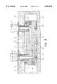
- FIG. 1is a top plan view of the coinjection molding system partially broken away;
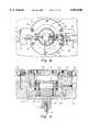
- FIG. 2is a cross-sectional side view of the coinjection molding system taken along line 2--2 of FIG. 1;
- FIG. 3is a schematic cross-sectional view similar to FIG. 2 showing the injection of skin material into the mold cavity;
- FIG. 4is a schematic cross-sectional view similar to FIG. 3 showing the injection of core material into the mold cavity;
- FIG. 5is a fragmentary cross-sectional side-view of the injection nozzle of the injection molding machine and the hot-runner manifold taken along line 5--5 of FIG. 1;
- FIG. 6is an enlarged fragmentary cross-sectional view taken along line 6--6 of FIG. 1;
- FIG. 7is a plan cross-sectional view of the nozzle taken along line 7--7 of FIG. 6;
- FIG. 8is a top plan view of the three position actuator seated in a cavity in the top clamp plate as taken along lines 8--8 of FIG. 6;
- FIG. 9is a cross-sectional side view of the actuator of FIG. 8 taken along line 9--9 of FIG. 8;
- FIGS. 10, 11 and 12are schematic cross sectional side views of the actuator of FIG. 9, shown in three respective positions;
- FIG. 11ashows an alternative piston positioning used to attain the same valve pin position shown in FIG. 11;
- FIG. 13is a schematic cross-sectional view of the nozzle tip of FIG. 6 in the closed position
- FIG. 14is similar to FIG. 13 with the valve pin in the middle position permitting skin injection;
- FIG. 15is similar to FIG. 13 with the valve pin in the open position
- FIG. 16is an alternative embodiment of a coinjection molding nozzle
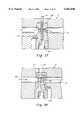
- FIG. 17is an enlarged fragmentary cross-sectional view of the manifold skin shut-off of FIGS. 2, 3, 4 and 6, shown in the closed position;
- FIG. 18is an alternative manifold configuration that uses a ball-check to prevent skin back flow through manifold channel 15;
- FIGS. 19 and 20are alternative embodiments of the skin shut-off of FIG. 17, shown in the closed position.
- FIGS. 1-5show one embodiment of the coinjection molding system 1 according to the present invention.
- the systemincludes bores 3 and 5 within inlets 44 and 46 mounted to a hot runner manifold 11 (see FIG. 5).
- Inlets 44 and 46receive the injection molding nozzles 7 and 9, respectively, from two injection molding machines.
- Machine nozzle 7injects core material into inlet 44 while machine nozzle 9 injects skin material into inlet 46.
- the bores 3 and 5feed into a distribution system of the hot runner manifold 11.
- the hot runner manifold 11includes distribution channels 13 and 15 for feeding core and skin material, respectively, to injection molding nozzles 17.
- a multiple gate, single cavity, systemis shown, the invention is not limited to multiple gate applications.
- the injection molding machinecould be directly coupled to a single nozzle, or spue bushing, 17.
- Nozzle 17includes bores 19 and 21 therethrough for communicating with and receiving molten material from core channel 13 and skin channel 15 in the manifold 11.
- the injection molding nozzle 17injects molten material into mold cavity 23 in which the molded part is formed.
- heat pipes 84are used to uniformly distribute heat, generated by tubular heater 12 and manifold 11, to nozzle 17, and keep the skin and core materials at their optimum processing temperature.
- the tubular heater 12is partially shown in the fragmentary view of FIG. 2, and in FIG. 7, and is mounted to and extends along the length of the nozzle 17.
- the inventionis not limited, however, to a particular type of nozzle heater, and other nozzle heaters such as helical heaters can be used.
- the mold cavity 23is formed by mold parts 25 and 27. Nozzles 17 are disposed within recesses 29 of mold part 27.
- a valve pin 31is located in a central bore in the injection molding nozzle 17. The valve pin 31 can be longitudinally displaced within the nozzle 17 and opens and closes the gate 33 to the mold, as well as the bore 19 through which the core material flows. As explained in greater detail hereinafter, the valve pin 31 will have three possible positions:1) a closed position in which the gate 33 is closed and skin and core material are shut-off; 2) a middle position in which core material is shut-off and skin material is not shut-off, and 3) an open position where both skin and core material are not shut-off.
- the valve pin 31can be longitudinally displaced within the nozzle 17 by a three-position actuator 34.
- the actuator 34is mounted in top clamp plate 36 which together with mold part 27 provides a space 38 in which the manifold 11 is located.
- An additional two-position actuator 40is provided to shut-off skin material traveling in channel 15 of the manifold 11.
- the actuator 40is also located n top clamp plate 36 and actuates the valve pin 42 that opens and closes channel 15 of manifold 11.
- FIGS. 3 and 4represent schematic views of the manifold 11 and top clamp plate 36 so as to better show the flow of skin and core material through the manifold channels 13 and 15.
- the manifoldis completely covered by the top clamp plate 36, and the machine nozzles 7 and 9 inject core and skin material respectively into bores 3 and 5 within inlets 44 and 46, respectively.
- Inlets 44 and 46mate with machine nozzles 7 and 9, respectively, are threadably mounted in manifold 11 at 48, and set within top clamp plate 36. Spacers 50 separate and insulate the heated manifold from the cooled mold 27. Heat pipes 52 and 54 within inlets 44 and 46 serve to maintain the molten material at its processing temperature when passing through inlets 44 and 46 by pulling heat out of the manifold. Pin 56 serves to center the manifold 11 with respect to the mold 27.
- the manifolddoes not extend above the top clamp plate, but is covered by it, and further the machine nozzles 7 and 9 are not directly connected to the manifold 11 but are connected via inlets 44 and 46 which pass through the top clamp plate 36.
- FIGS. 3, 4, 13, 14 and 15The operation of the preferred embodiment of the preferred system of FIGS. 1-5 will now be described with respect to FIGS. 3, 4, 13, 14 and 15.
- FIG. 13shows the nozzle in the closed position with core and skin material ready to be injected into the cavity 23.
- the valve pinhas moved from the closed position to a second or middle position in which skin flow from bore 21 of the nozzle 17 into the cavity 23 begins, and core flow from bore 19 of the nozzle is still shut off.
- the valve pinmoves to the open or third position in which core material is injected from bore 19 of nozzle 17 out of gate 33.
- the core shut-offis open, the skin barrel from the injection molding machine is either slowed down to about 10% or held. Injection of a small amount of skin material while the core material is being injected helps maintain the layer of skin material about the gate.
- core materialInjection of core material from the injection molding machine is then stopped.
- the valve pinis moved back to the middle position shutting off the core, while the final 5% to 10% of skin material is injected to assure that skin material covers the gate area, and also cleans out the gate area in the nozzle 17 of all core material so that on the next injection cycle only skin material initially enters the part.
- core materialwill constitute about 25-50% of the molded part, but this percentage will vary according to the application.
- valve-actuated gateenables the gates to be sequentially opened and closed.
- sequential gatingenables the location of weld lines, that is, the location in the cavity where the molten material from one gate meets the molten material from a different gate, to be moved.
- a weld linecan result in a visible imperfection in the part, and can be structurally weaker than the rest of the molded part.
- Sequential gatingenables weld lines to be eliminated, or moved to areas of the part where mechanical stresses are relatively low.
- the nozzleincludes tip 58, sleeve 60 and insert 62, best shown in FIGS. 6 and 13-16.
- Insert 62includes bores 64 and 66 for communicating with bores 19 and 21 and receiving the core material and skin material from the nozzle 17. Bore 64 also accommodates the valve pin 31 as the core material travels through the center of the insert 62 in about the valve pin 31. Due to the difficulty of machining irregularly shaped bore 64 through the insert 62, the insert includes two pieces 62a and 62b which meet at 63. The insert 62 forms a seal with the valve pin 31 at 72 to prevent core material from traveling up through the nozzle 17 to the actuator.
- the skin materialtravels through bore 66 about an annular grove 68 about the periphery of insert 62.
- the annular grovefacilitates the uniform flow of skin material as indicated by arrow 70 in FIG. 14.
- the insert 62is constructed to form a seal with the valve pin 31 when the valve pin is in the middle or closed position which prevents core material from leaking out of the insert 62, and mixing with skin material. As seen in FIG. 14, when shutting off the core outlet in the middle position, the seal formed by the valve pin and the insert 62 also prevents the skin material from being injected into the bore 64 which contains the core material, and thus prevents skin and core material from being mixed together.
- the insert 62can be made of tool steel, such as D2.
- Sleeve 60is seated on insert 62 at 74.
- Sleeve 60 and insert 62are constructed such that there is a space 76 formed therebetween about which skin material flows.
- Sleeve 60can be made of beryllium copper.
- Tip 58is threadably mounted on nozzle 17 and acts to hold the sleeve 60 and insert 62 in place.
- the gate 33is formed in the tip 58.
- the tipis machined to form a seal 78 with the mold, to prevent molded material from entering air space 29 about the nozzle 17.
- Tip 58can be made of stainless steel-420.
- An insulation space 80is formed between the tip 58 and sleeve 60 to minimize heat loss from the nozzle to the mold. Seal 82 prevents molded material from entering this insulation space 80.
- a three-position actuator 34is provided in order to move the valve pin 31 to its closed, middle and open positions.
- the actuatoris described with reference to FIGS. 7-12.
- the actuatoris mounted in top clamp plate 36 and includes hydraulic lines 86, 88 and 90.
- a pneumatic actuatorcan be used.
- the actuatorincludes an actuator cylinder 92 which is bolted to the top clamp plate 36 via screws 94.
- the actuatorincludes two movable pistons 96 and 98. Piston 96 is slidably movable within piston 98. The longitudinal movement of piston 96 causes longitudinal movement of valve pin 31 which is threadably mounted to piston 96 at 100.
- the longitudinal movement of the piston 96is limited in one direction by the top of the piston 98 and in the opposite direction by ring 102 which is also mounted within piston 98.
- the movement of the piston 98is limited in one direction by the actuator cylinder 92 at 104.
- the longitudinal displacement of the piston 98is also limited in the opposite direction by actuator cap 106 which is threadably mounted to actuator cylinder 92.
- FIGS. 10-12represent a schematic cross section to facilitate an understanding of the operation of the actuator 34, and specifically, the pressurization of the hydraulic lines 86, 88 and 90.
- the actuator piston 98 and actuator piston 96are in the down position and hydraulic lines 86 and 90 are pressurized to exert downward pressure indicated by arrows 108 on each piston, as seen in FIG. 10.
- O-rings 110provide a seal against leakage of hydraulic fluid.
- FIG. 11shows the actuator position when the valve pin is in the position shown in FIG. 14, i.e., the middle position in which core flow is shut off and skin flow is permitted.
- the actuatorWhen the valve pin is in the third or open position permitting core flow as shown in FIG. 15, the actuator is in the position shown in FIG. 12 in which hydraulic line 88 is pressurized but 86 and 90 are unpressurized causing piston 98 to be longitudinally displaced up to the actuator cap 106 by a pressure exerted on the bottom of the piston 98 as indicated by arrows 114.
- FIG. 11Ashows an alternative embodiment of the actuator when the valve pin is in the middle position as shown in FIG. 14.
- the valve pinis in the same position, and correspondingly, the piston 96 is in the same position.
- thisis accomplished by pressurizing line 86.
- Line 90is depressurized.
- piston 98is free to move into its uppermost position shown in FIG. 11A, bearing against the actuator cap 106. Movement of the piston 98 is caused by pressure exerted from the line 86 on the outer edge of the piston 98 indicated by arrows 113.
- an actuator 40is provided to stop the flow of skin material through the manifold channel 15.
- An actuatoris provided for each nozzle 17 to shut off the flow of skin material to that particular nozzle.
- the manifold shut-offsare used to control the flow of skin material through each nozzle, and can be used along with the valve pin core shut-off to sequentially fill the part.
- the manifold shut-offsenable core material to be injected out of one nozzle, and skin material to be injected out another nozzle, simultaneously, while pressure is maintained on both injection machine barrels (i.e., skin and core).
- the manifold shut-offsenable greater profitability with respect to nozzle sequencing and greater control of the location of weld lines.
- Simultaneous skin injection from one nozzle and core injection from a second nozzleis accomplished, for example, by shutting off skin material in the manifold associated with one nozzle, injecting core material out of that nozzle, and injecting skin material out a second nozzle by placing the valve pin of the second nozzle in the middle position shown in FIG. 14.
- the actuators 40 used for the manifold shut-offare two-position hydraulic actuators. Pneumatic actuators can also be used. Another function of the skin shut-offs located in the manifold is to prevent possible back flow of skin material in the hot runner. During core injection, if a pressure differential exists between the gates, it is possible for core material to flow into the skin channel instead of the part. If core material enters the skin channel, it can cause contamination of the skin material with the core material. As a result, core material may appear on the part surface which will render the part unusable.
- the skin shut-off when used with the core shut-offcan be used to completely control the skin-core-skin sequence in each nozzle independently while pressure is maintained on both machine barrels (i.e., skin and core).
- the manifoldscan include like manifold shut-offs for the core material, to individually control the flow of core material to each nozzle.
- FIG. 17One embodiment of the manifold shut-off used with actuator 40 is shown in FIG. 17.
- the actuator 40not shown in FIG. 17 (see FIGS. 2-4 and 6), is coupled to valve pin 42, and longitudinally displaces valve pin 42 to the open and closed positions, respectively.
- the valve pinis shown in the closed position.
- the end 114 of the valve pinblocks skin flow through passage 116 of plug 118.
- a set screw 130holds the plug 118 in place.
- FIG. 18is an alternative embodiment of the present invention which is used to prevent the backflow of skin material through the manifold channel 15.
- a ball check 120is provided which is shown in FIG. 18 in the closed position preventing the backflow of skin material through the channel 15.
- the ball checkis mounted within a recess bore of housing 122.
- the ball checkmoves to the position showed by the dash line to permit skin material flow thereabout.
- the ball checkis held within the housing 122 by a pin 128.
- a set screw 130holds the assembly in place.
- FIG. 19shows a valve pin 42 attached to a two-position actuator 40 (not shown).
- the shut-offis shown in the closed position in FIG. 19.
- a plug 132 having a channel 134 bored therethrough for permitting skin material flowhas a central bore that receives valve pin 42.
- Valve pin 42has an end in which a channel 136 is machined therethrough.
- a channel 136does not mate with the bore 134 of the plug 132.
- the valve pinis longitudinally displaced to its open position by the actuator 40, the channel 136 is aligned with the bore 134 to permit the flow of skin material.
- FIG. 20Another alternative embodiment of the manifold skin shut-off of FIG. 17 is shown in FIG. 20, which again shows the valve pin 42 attached to a two-position actuator 40 (not shown).
- plug 132has an irregular shaped channel board therethrough 138.
- the end of valve pin 140which is in the closed position, has a (curved surface which, when valve pin 42 is longitudinally displaced to the open position, provides a smooth surface aligned with inner surface 142 of bore 138 as indicated by dashed line 144.
- An advantage of this configurationis that only a minimal side load is exerted on the valve pin 42 by the injected skin material, as compared to the embodiments of FIGS. 17 and 19
- FIG. 16An alternative embodiment of the coinjection nozzle and actuator is shown in FIG. 16 in which only a two position actuator (not shown) is used to move the valve pin 31 in one of two positions. In one position the core channel 64 of the insert 62 is shut-off as shown in FIG. 16, and in the second or open position the valve pin 31 is pulled back to open the bore 64 within insert 62 to permit the flow of core material. (The open position of the valve pin is shown in a dashed line).
- FIG. 16shows a "thermal" gate version rather than a valve gate version of coinjection. In the thermal gate version, the coinjection cycle ends by having skin material freeze off in the gate 33, rather than by having a valve pin close the gate. The thermal gate avoids the need for a three position actuator, while the valve gate version offers a wider processing window with less chance of stringing or drooling at the gate.
Landscapes
- Engineering & Computer Science (AREA)
- Manufacturing & Machinery (AREA)
- Mechanical Engineering (AREA)
- Moulds For Moulding Plastics Or The Like (AREA)
- Injection Moulding Of Plastics Or The Like (AREA)
Abstract
Description
Claims (27)
Priority Applications (8)
| Application Number | Priority Date | Filing Date | Title |
|---|---|---|---|
| US08/922,208US6062840A (en) | 1997-09-02 | 1997-09-02 | Hot runner system for coinjection molding |
| EP98660085AEP0901896A3 (en) | 1997-09-02 | 1998-08-28 | Hot runner system for coinjection molding |
| CA002360509ACA2360509A1 (en) | 1997-09-02 | 1998-09-01 | Hot runner system for coinjection molding |
| CA002246771ACA2246771C (en) | 1997-09-02 | 1998-09-01 | Hot runner system for coinjection molding |
| US09/434,928US6287107B1 (en) | 1997-09-02 | 1999-11-05 | Apparatus for proportionally controlling fluid delivery to a mold |
| US09/434,718US6309208B1 (en) | 1997-06-13 | 1999-11-05 | Apparatus for proportionally controlling fluid delivery to a mold |
| US09/518,982US6261075B1 (en) | 1997-09-02 | 2000-03-03 | Hot runner system for coinjection molding |
| US09/618,666US6638049B1 (en) | 1997-06-13 | 2000-07-18 | Apparatus and method for proportionally controlling fluid delivery to readily replaceable mold inserts |
Applications Claiming Priority (1)
| Application Number | Priority Date | Filing Date | Title |
|---|---|---|---|
| US08/922,208US6062840A (en) | 1997-09-02 | 1997-09-02 | Hot runner system for coinjection molding |
Related Parent Applications (1)
| Application Number | Title | Priority Date | Filing Date |
|---|---|---|---|
| US08/874,962Continuation-In-PartUS5894025A (en) | 1997-06-13 | 1997-06-13 | Valve pin actuator |
Related Child Applications (2)
| Application Number | Title | Priority Date | Filing Date |
|---|---|---|---|
| US09/063,762Continuation-In-PartUS6361300B1 (en) | 1997-06-13 | 1998-04-21 | Manifold system having flow control |
| US09/518,982ContinuationUS6261075B1 (en) | 1997-09-02 | 2000-03-03 | Hot runner system for coinjection molding |
Publications (1)
| Publication Number | Publication Date |
|---|---|
| US6062840Atrue US6062840A (en) | 2000-05-16 |
Family
ID=25446700
Family Applications (2)
| Application Number | Title | Priority Date | Filing Date |
|---|---|---|---|
| US08/922,208Expired - LifetimeUS6062840A (en) | 1997-06-13 | 1997-09-02 | Hot runner system for coinjection molding |
| US09/518,982Expired - LifetimeUS6261075B1 (en) | 1997-09-02 | 2000-03-03 | Hot runner system for coinjection molding |
Family Applications After (1)
| Application Number | Title | Priority Date | Filing Date |
|---|---|---|---|
| US09/518,982Expired - LifetimeUS6261075B1 (en) | 1997-09-02 | 2000-03-03 | Hot runner system for coinjection molding |
Country Status (3)
| Country | Link |
|---|---|
| US (2) | US6062840A (en) |
| EP (1) | EP0901896A3 (en) |
| CA (1) | CA2246771C (en) |
Cited By (73)
| Publication number | Priority date | Publication date | Assignee | Title |
|---|---|---|---|---|
| WO2001062488A1 (en) | 2000-02-24 | 2001-08-30 | Conix Corporation | Integrated co-injection molded vehicle components and methods of making the same |
| US6315549B1 (en)* | 1999-03-19 | 2001-11-13 | Husky Injection Molding Systems Ltd. | Hot tip insulator retainer |
| WO2002036323A1 (en)* | 2000-10-31 | 2002-05-10 | Incoe Corporation | Co-injection valve-gate bushing with separate material flow paths |
| US20020079603A1 (en)* | 2000-11-30 | 2002-06-27 | Bemis Manufacturing Company | Co-injection methods using endothermic-blowing agents and products made therefrom |
| US20020086086A1 (en)* | 1999-09-21 | 2002-07-04 | Mark Doyle | Curvilinear valve pin controller for injection molding |
| US6464909B1 (en) | 1998-04-21 | 2002-10-15 | Synventive Molding Solutions, Inc. | Manifold system having flow control |
| US20030012845A1 (en)* | 1998-04-21 | 2003-01-16 | Mark Doyle | Apparatus and method for utilizing an actuator for flow control valve gates |
| US6514440B1 (en) | 1998-04-21 | 2003-02-04 | Synventive Molding Solutions, Inc. | Apparatus and method for purging injection molding system |
| US20030030179A1 (en)* | 2001-08-10 | 2003-02-13 | Satoshi Kajikawa | Nozzle for injection molding and injection molding machine |
| US6585505B2 (en) | 1998-04-21 | 2003-07-01 | Synventive Molding Solutions, Inc. | Machine for proportionally controlling fluid delivery to a mold |
| US6589039B1 (en) | 1998-04-21 | 2003-07-08 | Synventive Molding Solutions, Inc. | Controlled injection using manifold having multiple feed channels |
| US6599116B2 (en) | 1997-06-13 | 2003-07-29 | Synventive Molding Solutions, Inc. | Valve pin actuator |
| US6632079B1 (en) | 1998-04-21 | 2003-10-14 | Synventive Molding Solutions, Inc. | Dynamic feed control system |
| US6638049B1 (en) | 1997-06-13 | 2003-10-28 | Synventive Molding Solutions, Inc. | Apparatus and method for proportionally controlling fluid delivery to readily replaceable mold inserts |
| US20030214065A1 (en)* | 2001-12-26 | 2003-11-20 | Synventive Molding Solutions, Inc. | Non-coaxial injection molding valve flow control |
| US6683283B2 (en) | 2002-05-10 | 2004-01-27 | Dynisco Hot Runners Inc. Canada | Apparatus and method for heating injection molding fluid |
| US20040047942A1 (en)* | 1999-09-21 | 2004-03-11 | Synventive Molding Solutions, Inc. | Injection molding flow control apparatus and method |
| US20040047935A1 (en)* | 1998-04-21 | 2004-03-11 | Synventive Molding Solutions, Inc. | Apparatus and method for simulating an injection molding process |
| US20040051195A1 (en)* | 2002-09-18 | 2004-03-18 | Isao Okamura | Metering device for a nozzle of an injection molding apparatus |
| US20040109916A1 (en)* | 2002-12-03 | 2004-06-10 | Mold-Masters Limited | Hot runner co-injection nozzle |
| US20040161490A1 (en)* | 2003-02-13 | 2004-08-19 | Denis Babin | Valve gated injection molding system with independent flow control |
| US20040166189A1 (en)* | 2003-02-25 | 2004-08-26 | Mold-Masters Limited | Injection molding system with flow control |
| US20050255187A1 (en)* | 2004-05-14 | 2005-11-17 | University Of Massachusetts | Methods and devices for melt pressure regulation |
| US6974556B2 (en) | 2000-02-29 | 2005-12-13 | Bemis Manufacturing Company | Co-injection apparatus for injection molding |
| US20060097083A1 (en)* | 2003-01-31 | 2006-05-11 | Otto Hofstetter | Coinjection nozzle |
| US7147458B2 (en) | 2002-10-25 | 2006-12-12 | Mold Hotrunner Solutions, Inc. | Apparatus for heating injection molding fluid |
| US20070212503A1 (en)* | 2006-03-07 | 2007-09-13 | Bway Corporation | Multi-material container |
| US20070278708A1 (en)* | 2006-05-31 | 2007-12-06 | Graham Packaging Company, Lp | Controlling delivery of polymer material in a sequential injection molding process |
| US20090117219A1 (en)* | 2005-04-07 | 2009-05-07 | Jonathon Fischer | Configurable Manifold |
| WO2010132381A1 (en)* | 2009-05-13 | 2010-11-18 | Husky Injection Molding Systems Ltd | Hot-runner system having non-structurally supportive heat insulator including visible material |
| US7997895B1 (en) | 2010-04-06 | 2011-08-16 | Mold Hotrunner Solutions Inc. | Injection apparatus for injection molding of thermoplastic parts |
| US8047836B2 (en) | 2010-04-06 | 2011-11-01 | Mold Hotrunner Solutions Inc. | Nozzle valve gate apparatus with wiper seal |
| US8091202B2 (en) | 2009-05-06 | 2012-01-10 | Synventive Molding Solutions, Inc. | Method and apparatus for coupling and uncoupling an injection valve pin |
| US20120237631A1 (en)* | 2009-12-08 | 2012-09-20 | Husky Injection Molding Systems Ltd. | Hot-Runner System having Manifold Assembly Manufactured in Accordance with Free-Form-Fabrication |
| US20130099414A1 (en)* | 2011-10-21 | 2013-04-25 | Berry Plastics Corporation | Process for molding a closure-support ring of a container lid |
| US8715547B2 (en) | 2011-02-24 | 2014-05-06 | Mold-Masters (2007) Limited | Closed loop control of auxiliary injection unit |
| WO2014134376A1 (en) | 2013-02-28 | 2014-09-04 | Synventive Molding Solutions, Inc. | Fast acting reduced velocity pin control |
| WO2015066004A1 (en) | 2013-10-28 | 2015-05-07 | Synventive Molding Solutions, Inc. | Reduced velocity control based on sensed system condition |
| US20150158217A1 (en)* | 2012-06-21 | 2015-06-11 | Husky Injection Molding Systems Ltd. | Shooting Pot Circuit Valve |
| WO2015105777A1 (en) | 2014-01-08 | 2015-07-16 | Synventive Molding Solutions, Inc. | Valve pin and nozzle configuration and method of control |
| WO2015108895A1 (en) | 2014-01-15 | 2015-07-23 | Synventive Molding Solutions, Inc. | Two material injection molding apparatus component and additive manufacturing process therefor |
| WO2016153608A1 (en) | 2015-03-20 | 2016-09-29 | Synventive Molding Soulutions, Inc. | Actuator cooling apparatus and method |
| USD777446S1 (en) | 2015-07-23 | 2017-01-31 | Colgate-Palmolive Company | Oral care implement handle |
| US20170066169A1 (en)* | 2015-09-08 | 2017-03-09 | Samsung Electronics Co., Ltd. | Mobile phone case and injection mold for the same |
| WO2017066283A1 (en) | 2015-10-13 | 2017-04-20 | Synventive Molding Solutions, Inc. | Valve monitoring method and apparatus |
| WO2017088044A1 (en)* | 2015-11-23 | 2017-06-01 | Husky Injection Molding Systems Ltd. | Valve stem actuation |
| US9802347B2 (en) | 2015-02-02 | 2017-10-31 | Colgate-Palmolive Company | Method of forming an oral care implement |
| CN107322886A (en)* | 2017-08-25 | 2017-11-07 | 珠海市春生五金工业有限公司 | Change mould method with the plastic parts, mould and mould for keeping off electric part |
| WO2017200517A1 (en) | 2016-05-16 | 2017-11-23 | Synventive Molding Solutions, Inc. | Position detector |
| WO2017210169A1 (en) | 2016-06-01 | 2017-12-07 | Synventive Molding Solutions, Inc. | Controller arrangement for injection molding system |
| WO2017214387A1 (en) | 2016-06-09 | 2017-12-14 | Synventive Molding Solutions, Inc. | Cable transmission of actuator control for injection molding system |
| WO2018017807A2 (en) | 2016-07-20 | 2018-01-25 | Synventive Molding Solutions, Inc. | Injection molding apparatus and method for automatic cycle to cycle cavity injection |
| EP3299140A1 (en) | 2013-06-24 | 2018-03-28 | Synventive Molding Solutions, Inc. | Injection molding flow control apparatus and method |
| WO2018089243A1 (en) | 2016-11-14 | 2018-05-17 | Synventive Molding Solutions, Inc. | Actuator cooling apparatus and method |
| EP3335854A1 (en) | 2013-08-26 | 2018-06-20 | Synventive Molding Solutions, Inc. | Actuator system for rotating valve pin |
| WO2018148407A1 (en) | 2017-02-08 | 2018-08-16 | Synventive Molding Solutions, Inc. | Apparatus and method for controlling injection molding |
| WO2018169819A1 (en) | 2017-03-16 | 2018-09-20 | Synventive Molding Solutions, Inc. | Injection molding apparatus |
| WO2018175362A1 (en) | 2017-03-20 | 2018-09-27 | Synventive Molding Solutions, Inc. | Valve pin positions and velocity control method and apparatus |
| WO2018183810A1 (en) | 2017-03-31 | 2018-10-04 | Synventive Molding Solutions, Inc. | Rotary valve |
| WO2018194961A1 (en) | 2017-04-18 | 2018-10-25 | Synventive Molding Solutions, Inc. | Linear to linear valve pin drive during injection cycle |
| WO2018200660A1 (en) | 2017-04-26 | 2018-11-01 | Synventive Molding Solutions, Inc. | Double seal valve pin tip with vent |
| WO2019100085A1 (en) | 2017-11-14 | 2019-05-23 | Synventive Molding Solutions, Inc. | Actuator with eccentric pin drive |
| WO2020068285A1 (en) | 2018-08-17 | 2020-04-02 | Synventive Molding Solutions, Inc. | Disrupted flow through injection molding flow channel |
| WO2020176479A1 (en) | 2019-02-25 | 2020-09-03 | Synventive Molding Solutions, Inc. | Cooled electric actuator controlled injection |
| WO2020204980A1 (en) | 2019-04-02 | 2020-10-08 | Synventive Molding Solutions, Inc. | Nozzle heater |
| US10843395B2 (en) | 2017-11-21 | 2020-11-24 | Gateway Plastics, Inc. | Multi-layer injection molded container |
| WO2020242510A1 (en) | 2019-05-28 | 2020-12-03 | Synventive Molding Solutions, Inc. | Partially rotated eccentric drive for valve pin |
| WO2021034793A1 (en) | 2019-08-20 | 2021-02-25 | Synventive Molding Solutions, Inc. | Injection molding apparatus with integrated actuator electronic drive |
| WO2021080767A1 (en) | 2019-10-21 | 2021-04-29 | Synventive Molding Solutions, Inc. | Electric actuator drive for injection molding flow control |
| WO2021168391A1 (en) | 2020-02-20 | 2021-08-26 | Synventive Molding Solutions, Inc. | Sequential injection to multiple mold cavities |
| WO2022005530A1 (en) | 2020-07-01 | 2022-01-06 | Synventive Molding Solutions, Inc. | Method and apparatus for controlled injection fluid flow |
| WO2022076782A1 (en) | 2020-10-09 | 2022-04-14 | Synventive Molding Solutions, Inc. | Spring cushioned valve pin |
| WO2022125608A1 (en) | 2020-12-08 | 2022-06-16 | Synventive Molding Solutions, Inc. | Injection molding apparatus with cooled integrated actuator electronic drive |
Families Citing this family (26)
| Publication number | Priority date | Publication date | Assignee | Title |
|---|---|---|---|---|
| US20020121713A1 (en)* | 1997-06-13 | 2002-09-05 | Mark Moss | Apparatus and method for proportionally controlling fluid delivery to stacked molds |
| US6361300B1 (en) | 1998-04-21 | 2002-03-26 | Synventive Molding Solutions, Inc. | Manifold system having flow control |
| DE60005312T2 (en)* | 1999-03-18 | 2004-04-01 | Mold-Masters Ltd., Georgetown | DEVICE AND METHOD FOR MULTI-LAYER INJECTION MOLDING |
| US6440350B1 (en) | 1999-03-18 | 2002-08-27 | Mold-Masters Limited | Apparatus and method for multi-layer injection molding |
| BR0110155A (en)* | 2000-04-20 | 2002-12-31 | Decoma Exterior Trim Inc | Method for making a molded part, and, mold for making a molded part |
| US6887550B2 (en) | 2001-10-22 | 2005-05-03 | Omnova Solutions Inc. | Removable defined flange for in-mold coating containment |
| US6890469B2 (en) | 2001-10-22 | 2005-05-10 | Omnova Solutions Inc. | Selectively controlling in-mold coating flow |
| US7105231B2 (en)* | 2001-10-22 | 2006-09-12 | Omnova Solutions Inc. | In-mold coating barrier for a substrate injection orifice |
| US7045213B2 (en)* | 2001-10-22 | 2006-05-16 | Omnova Solutions Inc. | In-mold coating injection inlet flow control |
| US6676877B2 (en)* | 2002-04-03 | 2004-01-13 | Omnova Solutions Inc. | Mold runner for prevention of in-mold coating flow |
| EP1567313B1 (en)* | 2002-11-22 | 2008-10-01 | Omnova Solutions Inc. | Method for modifying and using existing injection mould machines to utilize as in-mould coating apparatus |
| US20040121034A1 (en)* | 2002-12-10 | 2004-06-24 | Mcbain Douglas S. | Integral injection molding and in-mold coating apparatus |
| ATE410287T1 (en)* | 2002-12-12 | 2008-10-15 | Omnova Solutions Inc | METHOD FOR MANUFACTURING AND USING A TOOL |
| US7207796B2 (en)* | 2004-07-01 | 2007-04-24 | Husky Injection Moldiing Systems Ltd. | Hot runner coinjection nozzle with thermally separated melt channels |
| US7648669B2 (en)* | 2004-11-30 | 2010-01-19 | Bemis Manufacturing Company | Injection-molding system and method |
| US7329112B2 (en)* | 2005-01-04 | 2008-02-12 | Plastic Engineering & Technical Services, Inc. | Injection molding system for injection molding a plurality of materials |
| CN103209814B (en) | 2010-09-21 | 2015-11-25 | 马斯特模具(2007)有限公司 | Inject injection molding system of hot runner altogether |
| US9498911B2 (en) | 2010-09-21 | 2016-11-22 | Mold-Masters (2007) Limited | Coinjection hot runner injection molding system |
| US9073246B2 (en) | 2011-09-21 | 2015-07-07 | Mold-Masters (2007) Limited | Coinjection hot runner injection molding system |
| CN103857514B (en)* | 2011-10-11 | 2016-09-21 | 博里利斯股份公司 | For injection molding distribution system |
| CH710339A1 (en) | 2014-11-06 | 2016-05-13 | Fostag Formenbau Ag | Co-injection nozzle with integrated check valve for an injection molding apparatus for manufacturing multi-layer injection molding products. |
| CH710340A1 (en) | 2014-11-06 | 2016-05-13 | Fostag Formenbau Ag | Co-injection nozzle for an injection molding apparatus for manufacturing multi-layer injection molding products. |
| CN204640703U (en)* | 2015-04-22 | 2015-09-16 | 柳道万和(苏州)热流道系统有限公司 | Flip-over type TOP-TIP |
| US11938666B2 (en) | 2019-10-30 | 2024-03-26 | Creative Plastic Concepts, Llc | Side shot system, method, and tote manufactured therefrom |
| US12377589B2 (en) | 2019-10-30 | 2025-08-05 | Creative Plastic Concepts, Llc | Injection molding system, method, and tote manufactured therefrom |
| EP3878621B1 (en)* | 2020-03-13 | 2022-12-21 | Haidlmair Holding GmbH | Multicomponent injection moulding method |
Citations (28)
| Publication number | Priority date | Publication date | Assignee | Title |
|---|---|---|---|---|
| US4497621A (en)* | 1983-04-13 | 1985-02-05 | American Can Company | Apparatus for simultaneously driving valve means through co-injection nozzles of a multi-cavity injection molding machine |
| US4512730A (en)* | 1983-04-13 | 1985-04-23 | American Can Company | Polymer flow stream redirecting and feeding device |
| US4518344A (en)* | 1983-04-13 | 1985-05-21 | American Can Company | Methods and apparatus for maintaining a pressure contact seal between nozzles and cavities of an on-line injection molding machine |
| US4657496A (en)* | 1984-06-04 | 1987-04-14 | Gifu Husky Co., Ltd. | Hot-runner mold for injection molding |
| US4712990A (en)* | 1983-04-13 | 1987-12-15 | American Can Company | Apparatus for injection molding and injection blow molding multi-layer articles |
| US4717324A (en)* | 1986-05-12 | 1988-01-05 | Husky Injection Molding Systems, Inc. | Coinjection of hollow articles and preforms |
| DE3632928A1 (en)* | 1986-09-27 | 1988-03-31 | Battenfeld Maschfab | SPRAY HEAD FOR PRODUCING MULTILAYER MOLDED BODIES FROM THERMOPLASTIC PLASTIC MATERIAL |
| US4775308A (en)* | 1986-05-12 | 1988-10-04 | Husky Injection Molding Systems, Ltd. | Nozzle for coinjection of hollow articles and preforms |
| US4808101A (en)* | 1986-05-12 | 1989-02-28 | Husky Injection Molding Systems Ltd. | Tri-injection of hollow articles |
| US4863369A (en)* | 1986-05-12 | 1989-09-05 | Husky Injection Molding Systems Ltd. | Injection molding with shooting pots |
| US4892699A (en)* | 1983-04-13 | 1990-01-09 | American National Can Company | Methods for injection molding and injection blow molding multi-layer articles |
| US4895504A (en)* | 1983-04-13 | 1990-01-23 | American National Can Company | Apparatus for injection molding and injection blow molding multi-layer articles |
| US4925100A (en)* | 1983-04-13 | 1990-05-15 | American National Can Company | Methods and apparatus for injection molding and injection blow molding multi-layer articles, and articles made thereby |
| US4931246A (en)* | 1983-04-13 | 1990-06-05 | American National Can Company | Method for injection molding multi-layer articles |
| US4931234A (en)* | 1986-05-12 | 1990-06-05 | Husky Injection Molding Systems Ltd. | Coinjection of hollow articles and preforms |
| US4932858A (en)* | 1989-06-30 | 1990-06-12 | Gellert Jobst U | Injection molding system having dual feed bushing seated in manifold |
| US4934915A (en)* | 1983-04-13 | 1990-06-19 | American National Can Company | Apparatus for injection molding multi-layer articles |
| EP0378138A2 (en)* | 1989-01-13 | 1990-07-18 | Husky Injection Molding Systems Ltd. | Multilayer nozzle with equalized flow |
| US4946365A (en)* | 1983-04-13 | 1990-08-07 | American National Can Company | Apparatus for injection molding and injection blow molding multi-layer articles |
| US5028226A (en)* | 1986-07-05 | 1991-07-02 | Cmb Foodcan Plc | Multi-cavity, co-injection molding apparatus |
| US5037285A (en)* | 1983-04-13 | 1991-08-06 | American National Can Company | Apparatus for injection molding and injection blow molding multi-layer articles |
| US5093054A (en)* | 1988-03-31 | 1992-03-03 | Kyowa Electric & Chemical Co., Ltd. | Method for making a reflector of a satellite broadcasting receiving parabolic antenna |
| US5106284A (en)* | 1988-01-19 | 1992-04-21 | Kamaya Kagaku Kogyo Co., Ltd. | Three-layered container, a method and apparatus thereof |
| US5223275A (en)* | 1990-10-12 | 1993-06-29 | Gellert Jobst U | Multi-cavity injection moulding system |
| US5238378A (en)* | 1992-05-11 | 1993-08-24 | Gellert Jobst U | Coinjection molding apparatus having rotary axial actuating mechanism |
| US5286184A (en)* | 1991-04-15 | 1994-02-15 | The Japan Steel Works, Ltd. | Injection molding apparatus having two hot runner blocks for producing a composite article |
| US5523045A (en)* | 1983-04-13 | 1996-06-04 | American National Can Company | Methods for injection molding and blow-molding multi-layer plastic articles |
| US5545028A (en)* | 1994-08-16 | 1996-08-13 | Kona Corporation | Bushing tip for injection molding apparatus |
Family Cites Families (2)
| Publication number | Priority date | Publication date | Assignee | Title |
|---|---|---|---|---|
| US5112212A (en)* | 1991-05-02 | 1992-05-12 | Husky Injection Molding Systems Ltd. | Shooting pot with combined valve and piston |
| US5914138A (en) | 1996-09-27 | 1999-06-22 | Kortec, Inc. | Apparatus for throttle-valving control for the co-extrusion of plastic materials as interior core streams encased by outer and inner streams for molding and the like |
- 1997
- 1997-09-02USUS08/922,208patent/US6062840A/ennot_activeExpired - Lifetime
- 1998
- 1998-08-28EPEP98660085Apatent/EP0901896A3/ennot_activeWithdrawn
- 1998-09-01CACA002246771Apatent/CA2246771C/ennot_activeExpired - Lifetime
- 2000
- 2000-03-03USUS09/518,982patent/US6261075B1/ennot_activeExpired - Lifetime
Patent Citations (29)
| Publication number | Priority date | Publication date | Assignee | Title |
|---|---|---|---|---|
| US4497621A (en)* | 1983-04-13 | 1985-02-05 | American Can Company | Apparatus for simultaneously driving valve means through co-injection nozzles of a multi-cavity injection molding machine |
| US4512730A (en)* | 1983-04-13 | 1985-04-23 | American Can Company | Polymer flow stream redirecting and feeding device |
| US4518344A (en)* | 1983-04-13 | 1985-05-21 | American Can Company | Methods and apparatus for maintaining a pressure contact seal between nozzles and cavities of an on-line injection molding machine |
| US4712990A (en)* | 1983-04-13 | 1987-12-15 | American Can Company | Apparatus for injection molding and injection blow molding multi-layer articles |
| US5523045A (en)* | 1983-04-13 | 1996-06-04 | American National Can Company | Methods for injection molding and blow-molding multi-layer plastic articles |
| US5037285A (en)* | 1983-04-13 | 1991-08-06 | American National Can Company | Apparatus for injection molding and injection blow molding multi-layer articles |
| US4946365A (en)* | 1983-04-13 | 1990-08-07 | American National Can Company | Apparatus for injection molding and injection blow molding multi-layer articles |
| US4934915A (en)* | 1983-04-13 | 1990-06-19 | American National Can Company | Apparatus for injection molding multi-layer articles |
| US4931246A (en)* | 1983-04-13 | 1990-06-05 | American National Can Company | Method for injection molding multi-layer articles |
| US4892699A (en)* | 1983-04-13 | 1990-01-09 | American National Can Company | Methods for injection molding and injection blow molding multi-layer articles |
| US4895504A (en)* | 1983-04-13 | 1990-01-23 | American National Can Company | Apparatus for injection molding and injection blow molding multi-layer articles |
| US4925100A (en)* | 1983-04-13 | 1990-05-15 | American National Can Company | Methods and apparatus for injection molding and injection blow molding multi-layer articles, and articles made thereby |
| US4657496A (en)* | 1984-06-04 | 1987-04-14 | Gifu Husky Co., Ltd. | Hot-runner mold for injection molding |
| US4931234A (en)* | 1986-05-12 | 1990-06-05 | Husky Injection Molding Systems Ltd. | Coinjection of hollow articles and preforms |
| US4717324A (en)* | 1986-05-12 | 1988-01-05 | Husky Injection Molding Systems, Inc. | Coinjection of hollow articles and preforms |
| US4808101A (en)* | 1986-05-12 | 1989-02-28 | Husky Injection Molding Systems Ltd. | Tri-injection of hollow articles |
| US4863369A (en)* | 1986-05-12 | 1989-09-05 | Husky Injection Molding Systems Ltd. | Injection molding with shooting pots |
| US4775308A (en)* | 1986-05-12 | 1988-10-04 | Husky Injection Molding Systems, Ltd. | Nozzle for coinjection of hollow articles and preforms |
| US5028226A (en)* | 1986-07-05 | 1991-07-02 | Cmb Foodcan Plc | Multi-cavity, co-injection molding apparatus |
| DE3632928A1 (en)* | 1986-09-27 | 1988-03-31 | Battenfeld Maschfab | SPRAY HEAD FOR PRODUCING MULTILAYER MOLDED BODIES FROM THERMOPLASTIC PLASTIC MATERIAL |
| US5106284A (en)* | 1988-01-19 | 1992-04-21 | Kamaya Kagaku Kogyo Co., Ltd. | Three-layered container, a method and apparatus thereof |
| US5093054A (en)* | 1988-03-31 | 1992-03-03 | Kyowa Electric & Chemical Co., Ltd. | Method for making a reflector of a satellite broadcasting receiving parabolic antenna |
| EP0378138A2 (en)* | 1989-01-13 | 1990-07-18 | Husky Injection Molding Systems Ltd. | Multilayer nozzle with equalized flow |
| US4932858A (en)* | 1989-06-30 | 1990-06-12 | Gellert Jobst U | Injection molding system having dual feed bushing seated in manifold |
| US5223275A (en)* | 1990-10-12 | 1993-06-29 | Gellert Jobst U | Multi-cavity injection moulding system |
| US5286184A (en)* | 1991-04-15 | 1994-02-15 | The Japan Steel Works, Ltd. | Injection molding apparatus having two hot runner blocks for producing a composite article |
| US5374178A (en)* | 1991-04-15 | 1994-12-20 | The Japan Steel Works, Ltd. | Multicavity injection mold having a plurality of hot runner blocks |
| US5238378A (en)* | 1992-05-11 | 1993-08-24 | Gellert Jobst U | Coinjection molding apparatus having rotary axial actuating mechanism |
| US5545028A (en)* | 1994-08-16 | 1996-08-13 | Kona Corporation | Bushing tip for injection molding apparatus |
Non-Patent Citations (2)
| Title |
|---|
| Injection Molding Magazine, Nov. 1996, "Coinjection hot runner basics". |
| Injection Molding Magazine, Nov. 1996, Coinjection hot runner basics .* |
Cited By (136)
| Publication number | Priority date | Publication date | Assignee | Title |
|---|---|---|---|---|
| US6599116B2 (en) | 1997-06-13 | 2003-07-29 | Synventive Molding Solutions, Inc. | Valve pin actuator |
| US6638049B1 (en) | 1997-06-13 | 2003-10-28 | Synventive Molding Solutions, Inc. | Apparatus and method for proportionally controlling fluid delivery to readily replaceable mold inserts |
| US20090028986A1 (en)* | 1998-04-21 | 2009-01-29 | Synventive Molding Solutions, Inc. | Injection molding flow control apparatus and method |
| US6769896B2 (en) | 1998-04-21 | 2004-08-03 | Synventive-Molding Solutions, Inc. | Manifold system having flow control |
| US6824379B2 (en) | 1998-04-21 | 2004-11-30 | Synventive Molding Solutions, Inc. | Apparatus for utilizing an actuator for flow control valve gates |
| US6464909B1 (en) | 1998-04-21 | 2002-10-15 | Synventive Molding Solutions, Inc. | Manifold system having flow control |
| US20030012845A1 (en)* | 1998-04-21 | 2003-01-16 | Mark Doyle | Apparatus and method for utilizing an actuator for flow control valve gates |
| US6514440B1 (en) | 1998-04-21 | 2003-02-04 | Synventive Molding Solutions, Inc. | Apparatus and method for purging injection molding system |
| US20080315445A1 (en)* | 1998-04-21 | 2008-12-25 | Synventive Molding Solutions, Inc. | Injection molding flow control apparatus and method |
| US6585505B2 (en) | 1998-04-21 | 2003-07-01 | Synventive Molding Solutions, Inc. | Machine for proportionally controlling fluid delivery to a mold |
| US6589039B1 (en) | 1998-04-21 | 2003-07-08 | Synventive Molding Solutions, Inc. | Controlled injection using manifold having multiple feed channels |
| US6767486B2 (en) | 1998-04-21 | 2004-07-27 | Synventive Molding Solutions, Inc. | Controlled injection using manifold having multiple feed channels |
| US20030155672A1 (en)* | 1998-04-21 | 2003-08-21 | Synventive Molding Solutions | Manifold system having flow control |
| US20030180409A1 (en)* | 1998-04-21 | 2003-09-25 | Dynisco Hotrunners, Inc. | Manifold system having flow control |
| US6632079B1 (en) | 1998-04-21 | 2003-10-14 | Synventive Molding Solutions, Inc. | Dynamic feed control system |
| US7569169B2 (en) | 1998-04-21 | 2009-08-04 | Synventive Molding Solutions, Inc. | Injection molding flow control apparatus and method |
| US20030203064A1 (en)* | 1998-04-21 | 2003-10-30 | Synventive Molding Solutions, Inc. | Controlled injection using manifold having multiple feed channels |
| US7901601B2 (en) | 1998-04-21 | 2011-03-08 | Synventive Molding Solutions, Inc. | Injection molding flow control apparatus and method |
| US8016581B2 (en) | 1998-04-21 | 2011-09-13 | Synventive Molding Solutions, Inc. | Injection molding flow control apparatus |
| US20040047935A1 (en)* | 1998-04-21 | 2004-03-11 | Synventive Molding Solutions, Inc. | Apparatus and method for simulating an injection molding process |
| US6315549B1 (en)* | 1999-03-19 | 2001-11-13 | Husky Injection Molding Systems Ltd. | Hot tip insulator retainer |
| US20020086086A1 (en)* | 1999-09-21 | 2002-07-04 | Mark Doyle | Curvilinear valve pin controller for injection molding |
| US20040047942A1 (en)* | 1999-09-21 | 2004-03-11 | Synventive Molding Solutions, Inc. | Injection molding flow control apparatus and method |
| US7234929B2 (en) | 1999-09-21 | 2007-06-26 | Synventive Molding Solutions, Inc. | Injection molding flow control apparatus and method |
| US20070224303A1 (en)* | 1999-09-21 | 2007-09-27 | Synventive Molding Solutions, Inc. | Injection molding flow control apparatus and method |
| US7419625B2 (en) | 1999-09-21 | 2008-09-02 | Synventive Molding Solutions, Inc. | Injection molding flow control method |
| WO2001062488A1 (en) | 2000-02-24 | 2001-08-30 | Conix Corporation | Integrated co-injection molded vehicle components and methods of making the same |
| US6974556B2 (en) | 2000-02-29 | 2005-12-13 | Bemis Manufacturing Company | Co-injection apparatus for injection molding |
| WO2002036323A1 (en)* | 2000-10-31 | 2002-05-10 | Incoe Corporation | Co-injection valve-gate bushing with separate material flow paths |
| US6964748B2 (en) | 2000-11-30 | 2005-11-15 | Bemis Manufacturing Company | Co-injection methods using endothermic-blowing agents and products made therefrom |
| US20020079603A1 (en)* | 2000-11-30 | 2002-06-27 | Bemis Manufacturing Company | Co-injection methods using endothermic-blowing agents and products made therefrom |
| US20030030179A1 (en)* | 2001-08-10 | 2003-02-13 | Satoshi Kajikawa | Nozzle for injection molding and injection molding machine |
| US20040155379A1 (en)* | 2001-08-10 | 2004-08-12 | Toshiba Machine Co., Ltd. | Nozzle for injection molding and injection molding machine |
| US20030214065A1 (en)* | 2001-12-26 | 2003-11-20 | Synventive Molding Solutions, Inc. | Non-coaxial injection molding valve flow control |
| US7029268B2 (en) | 2001-12-26 | 2006-04-18 | Synventive Molding Solutions, Inc. | Non-coaxial injection molding valve flow control |
| US20060127527A1 (en)* | 2001-12-26 | 2006-06-15 | Synventive Molding Solutions, Inc. | Non-coaxial injection molding valve flow control |
| US7597828B2 (en) | 2001-12-26 | 2009-10-06 | Synventive Molding Solutions, Inc. | Injection molding valve flow control |
| US20070273060A1 (en)* | 2001-12-26 | 2007-11-29 | Synventive Molding Solutions, Inc. | Injection molding valve flow control |
| US7270537B2 (en) | 2001-12-26 | 2007-09-18 | Synventive Molding Solutions, Inc. | Non-coaxial injection molding valve flow control |
| US6683283B2 (en) | 2002-05-10 | 2004-01-27 | Dynisco Hot Runners Inc. Canada | Apparatus and method for heating injection molding fluid |
| US20050266117A1 (en)* | 2002-09-18 | 2005-12-01 | Mold-Masters Limited | Metering device for a nozzle of a hot runner injection molding apparatus |
| US7192268B2 (en) | 2002-09-18 | 2007-03-20 | Mold-Masters Limited | Metering device for a nozzle of a hot runner injection molding apparatus |
| US6884061B2 (en) | 2002-09-18 | 2005-04-26 | Mold-Masters Limited | Metering device for a nozzle of an injection molding apparatus |
| US20040051195A1 (en)* | 2002-09-18 | 2004-03-18 | Isao Okamura | Metering device for a nozzle of an injection molding apparatus |
| US7147458B2 (en) | 2002-10-25 | 2006-12-12 | Mold Hotrunner Solutions, Inc. | Apparatus for heating injection molding fluid |
| US7175419B2 (en) | 2002-12-03 | 2007-02-13 | Mold-Masters Limited | Hot runner co-injection nozzle |
| US20040109916A1 (en)* | 2002-12-03 | 2004-06-10 | Mold-Masters Limited | Hot runner co-injection nozzle |
| US20060097083A1 (en)* | 2003-01-31 | 2006-05-11 | Otto Hofstetter | Coinjection nozzle |
| US7175420B2 (en) | 2003-02-13 | 2007-02-13 | Mold-Masters Limited | Valve gated injection molding system with independent flow control |
| US20040161490A1 (en)* | 2003-02-13 | 2004-08-19 | Denis Babin | Valve gated injection molding system with independent flow control |
| US20040166189A1 (en)* | 2003-02-25 | 2004-08-26 | Mold-Masters Limited | Injection molding system with flow control |
| US20050255187A1 (en)* | 2004-05-14 | 2005-11-17 | University Of Massachusetts | Methods and devices for melt pressure regulation |
| US20090117219A1 (en)* | 2005-04-07 | 2009-05-07 | Jonathon Fischer | Configurable Manifold |
| US20110008480A1 (en)* | 2005-04-07 | 2011-01-13 | Mold-Masters (2007) Limited | Configurable Manifold |
| US7802983B2 (en) | 2005-04-07 | 2010-09-28 | Mold-Masters (2007) Limited | Configurable manifold |
| US20070212503A1 (en)* | 2006-03-07 | 2007-09-13 | Bway Corporation | Multi-material container |
| US8118581B2 (en) | 2006-05-31 | 2012-02-21 | Graham Packaging Company, Lp | Injection molding apparatus for delivering multiple shots of materials to a plurality of mold cavities |
| US7892462B2 (en) | 2006-05-31 | 2011-02-22 | Graham Packaging Company, Llp | Controlling delivery of polymer material in a sequential injection molding process |
| US20100109181A1 (en)* | 2006-05-31 | 2010-05-06 | Graham Packaging Company, Lp | Controlling delivery of polymer material in a sequential injection molding process |
| US20110212204A1 (en)* | 2006-05-31 | 2011-09-01 | Graham Packaging Company, Lp | Controlling delivery of polymer material in a sequential injection molding process |
| US7651644B2 (en)* | 2006-05-31 | 2010-01-26 | Graham Packaging Company, Lp | Controlling delivery of polymer material in a sequential injection molding process |
| US20070278708A1 (en)* | 2006-05-31 | 2007-12-06 | Graham Packaging Company, Lp | Controlling delivery of polymer material in a sequential injection molding process |
| US8282388B2 (en) | 2009-05-06 | 2012-10-09 | Synventive Molding Solutions, Inc. | Apparatus for coupling and uncoupling an injection valve pin |
| US8091202B2 (en) | 2009-05-06 | 2012-01-10 | Synventive Molding Solutions, Inc. | Method and apparatus for coupling and uncoupling an injection valve pin |
| WO2010132381A1 (en)* | 2009-05-13 | 2010-11-18 | Husky Injection Molding Systems Ltd | Hot-runner system having non-structurally supportive heat insulator including visible material |
| US8535048B2 (en) | 2009-05-13 | 2013-09-17 | Husky Injection Molding Systems Ltd. | Hot-runner system having non-structurally supportive heat insulator including visible material |
| US20120237631A1 (en)* | 2009-12-08 | 2012-09-20 | Husky Injection Molding Systems Ltd. | Hot-Runner System having Manifold Assembly Manufactured in Accordance with Free-Form-Fabrication |
| US8678802B2 (en)* | 2009-12-08 | 2014-03-25 | Husky Injection Molding Systems Ltd. | Hot-runner system having manifold assembly manufactured in accordance with free-form-fabrication |
| EP2374595A1 (en) | 2010-04-06 | 2011-10-12 | Mold Hotrunner Solution, Inc. | Injection apparatus for injection molding of thermoplastic parts |
| US8047836B2 (en) | 2010-04-06 | 2011-11-01 | Mold Hotrunner Solutions Inc. | Nozzle valve gate apparatus with wiper seal |
| US7997895B1 (en) | 2010-04-06 | 2011-08-16 | Mold Hotrunner Solutions Inc. | Injection apparatus for injection molding of thermoplastic parts |
| US8940202B2 (en) | 2011-02-24 | 2015-01-27 | Mold-Masters (2007) Limited | Closed loop control of auxiliary injection unit |
| US8715547B2 (en) | 2011-02-24 | 2014-05-06 | Mold-Masters (2007) Limited | Closed loop control of auxiliary injection unit |
| US9186833B2 (en) | 2011-02-24 | 2015-11-17 | Mold-Masters (2007) Limited | Closed loop control of auxiliary injection unit |
| US20130099414A1 (en)* | 2011-10-21 | 2013-04-25 | Berry Plastics Corporation | Process for molding a closure-support ring of a container lid |
| US9056409B2 (en)* | 2011-10-21 | 2015-06-16 | Berry Plastics Corporation | Process for molding a closure-support ring of a container lid |
| US20150158217A1 (en)* | 2012-06-21 | 2015-06-11 | Husky Injection Molding Systems Ltd. | Shooting Pot Circuit Valve |
| US9296136B2 (en)* | 2012-06-21 | 2016-03-29 | Husky Injection Molding Systems Ltd | Shooting pot circuit valve |
| WO2014134376A1 (en) | 2013-02-28 | 2014-09-04 | Synventive Molding Solutions, Inc. | Fast acting reduced velocity pin control |
| EP3299140A1 (en) | 2013-06-24 | 2018-03-28 | Synventive Molding Solutions, Inc. | Injection molding flow control apparatus and method |
| EP3539747A1 (en) | 2013-06-24 | 2019-09-18 | Synventive Molding Solutions, Inc. | Injection molding flow-control apparatus and method |
| EP3357664A1 (en) | 2013-06-24 | 2018-08-08 | Synventive Molding Solutions, Inc. | Injection molding flow control apparatus and method |
| EP3335854A1 (en) | 2013-08-26 | 2018-06-20 | Synventive Molding Solutions, Inc. | Actuator system for rotating valve pin |
| EP3569380A1 (en) | 2013-10-28 | 2019-11-20 | Synventive Molding Solutions, Inc. | Reduced velocity control based on sensed system condition |
| WO2015066004A1 (en) | 2013-10-28 | 2015-05-07 | Synventive Molding Solutions, Inc. | Reduced velocity control based on sensed system condition |
| WO2015105777A1 (en) | 2014-01-08 | 2015-07-16 | Synventive Molding Solutions, Inc. | Valve pin and nozzle configuration and method of control |
| WO2015108895A1 (en) | 2014-01-15 | 2015-07-23 | Synventive Molding Solutions, Inc. | Two material injection molding apparatus component and additive manufacturing process therefor |
| US11577435B2 (en) | 2015-02-02 | 2023-02-14 | Colgate-Palmolive Company | System and method for forming an oral care implement |
| US10723052B2 (en) | 2015-02-02 | 2020-07-28 | Colgate-Palmolive Company | System and method for forming an oral care implement |
| US9802347B2 (en) | 2015-02-02 | 2017-10-31 | Colgate-Palmolive Company | Method of forming an oral care implement |
| WO2016153704A1 (en) | 2015-03-20 | 2016-09-29 | Synventive Molding Solutions, Inc. | Actuator cooling apparatus and method |
| EP3581359A1 (en) | 2015-03-20 | 2019-12-18 | Synventive Molding Solutions, Inc. | Actuator cooling apparatus and method |
| EP3744498A1 (en) | 2015-03-20 | 2020-12-02 | Synventive Molding Solutions, Inc. | Actuator cooling apparatus and method |
| EP3412425A1 (en) | 2015-03-20 | 2018-12-12 | Synventive Molding Solutions, Inc. | Actuator cooling apparatus and method |
| WO2016153703A1 (en) | 2015-03-20 | 2016-09-29 | Synventive Molding Solutions, Inc. | Actuator cooling apparatus and method |
| WO2016153608A1 (en) | 2015-03-20 | 2016-09-29 | Synventive Molding Soulutions, Inc. | Actuator cooling apparatus and method |
| EP3326777A1 (en) | 2015-03-20 | 2018-05-30 | Synventive Molding Solutions, Inc. | Actuator cooling method |
| USD887144S1 (en) | 2015-07-23 | 2020-06-16 | Colgate-Palmolive Company | Oral care implement |
| USD777446S1 (en) | 2015-07-23 | 2017-01-31 | Colgate-Palmolive Company | Oral care implement handle |
| USD840691S1 (en) | 2015-07-23 | 2019-02-19 | Colgate-Palmolive Company | Oral care implement |
| USD987298S1 (en) | 2015-07-23 | 2023-05-30 | Colgate-Palmolive Company | Oral care implement |
| US20170066169A1 (en)* | 2015-09-08 | 2017-03-09 | Samsung Electronics Co., Ltd. | Mobile phone case and injection mold for the same |
| WO2017066283A1 (en) | 2015-10-13 | 2017-04-20 | Synventive Molding Solutions, Inc. | Valve monitoring method and apparatus |
| WO2017088044A1 (en)* | 2015-11-23 | 2017-06-01 | Husky Injection Molding Systems Ltd. | Valve stem actuation |
| US11667066B2 (en) | 2015-11-23 | 2023-06-06 | Husky Injection Molding Systems Ltd. | Valve stem actuation |
| CN108367474A (en)* | 2015-11-23 | 2018-08-03 | 赫斯基注塑系统有限公司 | Valve stem actuation |
| JP2019502577A (en)* | 2015-11-23 | 2019-01-31 | ハスキー インジェクション モールディング システムズ リミテッドHusky Injection Molding Systems Limited | Valve stem operation |
| US10882233B2 (en) | 2015-11-23 | 2021-01-05 | Husky Injection Molding Systems Ltd. | Valve stem actuation |
| WO2017200517A1 (en) | 2016-05-16 | 2017-11-23 | Synventive Molding Solutions, Inc. | Position detector |
| WO2017210169A1 (en) | 2016-06-01 | 2017-12-07 | Synventive Molding Solutions, Inc. | Controller arrangement for injection molding system |
| WO2017214387A1 (en) | 2016-06-09 | 2017-12-14 | Synventive Molding Solutions, Inc. | Cable transmission of actuator control for injection molding system |
| EP3560677A1 (en) | 2016-07-20 | 2019-10-30 | Synventive Molding Solutions, Inc. | Injection molding apparatus and method for automatic cycle to cycle cavity in injection |
| EP3560678A1 (en) | 2016-07-20 | 2019-10-30 | Synventive Molding Solutions, Inc. | Injection molding apparatus and method for automatic cycle to cycle cavity in injection |
| WO2018017807A2 (en) | 2016-07-20 | 2018-01-25 | Synventive Molding Solutions, Inc. | Injection molding apparatus and method for automatic cycle to cycle cavity injection |
| WO2018017847A1 (en) | 2016-07-20 | 2018-01-25 | Synventive Molding Solutions, Inc. | Injection molding apparatus and method for automatic cycle to cycle cavity injection |
| WO2018089243A1 (en) | 2016-11-14 | 2018-05-17 | Synventive Molding Solutions, Inc. | Actuator cooling apparatus and method |
| WO2018148407A1 (en) | 2017-02-08 | 2018-08-16 | Synventive Molding Solutions, Inc. | Apparatus and method for controlling injection molding |
| WO2018169819A1 (en) | 2017-03-16 | 2018-09-20 | Synventive Molding Solutions, Inc. | Injection molding apparatus |
| WO2018175362A1 (en) | 2017-03-20 | 2018-09-27 | Synventive Molding Solutions, Inc. | Valve pin positions and velocity control method and apparatus |
| WO2018183810A1 (en) | 2017-03-31 | 2018-10-04 | Synventive Molding Solutions, Inc. | Rotary valve |
| WO2018194961A1 (en) | 2017-04-18 | 2018-10-25 | Synventive Molding Solutions, Inc. | Linear to linear valve pin drive during injection cycle |
| WO2018200660A1 (en) | 2017-04-26 | 2018-11-01 | Synventive Molding Solutions, Inc. | Double seal valve pin tip with vent |
| CN107322886A (en)* | 2017-08-25 | 2017-11-07 | 珠海市春生五金工业有限公司 | Change mould method with the plastic parts, mould and mould for keeping off electric part |
| WO2019100085A1 (en) | 2017-11-14 | 2019-05-23 | Synventive Molding Solutions, Inc. | Actuator with eccentric pin drive |
| US10843395B2 (en) | 2017-11-21 | 2020-11-24 | Gateway Plastics, Inc. | Multi-layer injection molded container |
| US11298861B2 (en) | 2017-11-21 | 2022-04-12 | Silgan Specialty Packaging Llc | Multi-layer injection molded container |
| WO2020068285A1 (en) | 2018-08-17 | 2020-04-02 | Synventive Molding Solutions, Inc. | Disrupted flow through injection molding flow channel |
| WO2020176479A1 (en) | 2019-02-25 | 2020-09-03 | Synventive Molding Solutions, Inc. | Cooled electric actuator controlled injection |
| WO2020204980A1 (en) | 2019-04-02 | 2020-10-08 | Synventive Molding Solutions, Inc. | Nozzle heater |
| WO2020242510A1 (en) | 2019-05-28 | 2020-12-03 | Synventive Molding Solutions, Inc. | Partially rotated eccentric drive for valve pin |
| WO2021034793A1 (en) | 2019-08-20 | 2021-02-25 | Synventive Molding Solutions, Inc. | Injection molding apparatus with integrated actuator electronic drive |
| WO2021080767A1 (en) | 2019-10-21 | 2021-04-29 | Synventive Molding Solutions, Inc. | Electric actuator drive for injection molding flow control |
| WO2021168391A1 (en) | 2020-02-20 | 2021-08-26 | Synventive Molding Solutions, Inc. | Sequential injection to multiple mold cavities |
| WO2022005530A1 (en) | 2020-07-01 | 2022-01-06 | Synventive Molding Solutions, Inc. | Method and apparatus for controlled injection fluid flow |
| WO2022076782A1 (en) | 2020-10-09 | 2022-04-14 | Synventive Molding Solutions, Inc. | Spring cushioned valve pin |
| WO2022125608A1 (en) | 2020-12-08 | 2022-06-16 | Synventive Molding Solutions, Inc. | Injection molding apparatus with cooled integrated actuator electronic drive |
Also Published As
| Publication number | Publication date |
|---|---|
| CA2246771A1 (en) | 1999-03-02 |
| CA2246771C (en) | 2002-01-22 |
| EP0901896A2 (en) | 1999-03-17 |
| US6261075B1 (en) | 2001-07-17 |
| EP0901896A3 (en) | 2003-04-09 |
Similar Documents
| Publication | Publication Date | Title |
|---|---|---|
| US6062840A (en) | Hot runner system for coinjection molding | |
| US6274075B1 (en) | Five layer injection molding apparatus having four position valve member actuating mechanism | |
| US6113381A (en) | Injection molding valve member actuating mechanism | |
| CA2253042C (en) | Method of three layer injection molding with sequential and simultaneous coinjection | |
| EP0911138B1 (en) | Injection molding apparatus having inter-manifold melt transfer bushings | |
| CA2247867C (en) | Multiple gating nozzle | |
| EP0911136B1 (en) | Sprue gated five layer injection molding apparatus and method for molding five layered products | |
| US5223275A (en) | Multi-cavity injection moulding system | |
| CA2367746C (en) | Apparatus and method for multi-layer injection molding | |
| EP0480223A1 (en) | Multi-cavity injection moulding system | |
| EP0624449A2 (en) | Method of molding plastic articles | |
| CA2225287C (en) | Multi-layer injection molding apparatus having three position valve member | |
| CA2360509A1 (en) | Hot runner system for coinjection molding | |
| CA2462150C (en) | Multiple gating nozzle | |
| EP1163098B1 (en) | Apparatus and method for multi-layer injection moulding | |
| RUNNER | SEQUENTIAL COINJECTION | |
| WO2002036323A1 (en) | Co-injection valve-gate bushing with separate material flow paths |
Legal Events
| Date | Code | Title | Description |
|---|---|---|---|
| AS | Assignment | Owner name:KONA CORPORATION, MASSACHUSETTS Free format text:ASSIGNMENT OF ASSIGNORS INTEREST;ASSIGNORS:LEE, CHRISTOPHER W.;MOSS, MARK D.;REEL/FRAME:009262/0615 Effective date:19980206 | |
| AS | Assignment | Owner name:DYNISCO HOTRUNNERS, INC., MASSACHUSETTS Free format text:CHANGE OF NAME;ASSIGNOR:KONA CORPORATION;REEL/FRAME:010061/0660 Effective date:19990112 | |
| FEPP | Fee payment procedure | Free format text:PAYOR NUMBER ASSIGNED (ORIGINAL EVENT CODE: ASPN); ENTITY STATUS OF PATENT OWNER: LARGE ENTITY | |
| STCF | Information on status: patent grant | Free format text:PATENTED CASE | |
| FEPP | Fee payment procedure | Free format text:PAYER NUMBER DE-ASSIGNED (ORIGINAL EVENT CODE: RMPN); ENTITY STATUS OF PATENT OWNER: LARGE ENTITY Free format text:PAYOR NUMBER ASSIGNED (ORIGINAL EVENT CODE: ASPN); ENTITY STATUS OF PATENT OWNER: LARGE ENTITY | |
| FEPP | Fee payment procedure | Free format text:PAYOR NUMBER ASSIGNED (ORIGINAL EVENT CODE: ASPN); ENTITY STATUS OF PATENT OWNER: LARGE ENTITY Free format text:PAYER NUMBER DE-ASSIGNED (ORIGINAL EVENT CODE: RMPN); ENTITY STATUS OF PATENT OWNER: LARGE ENTITY | |
| AS | Assignment | Owner name:SYNVENTIVE MOLDING SOLUTIONS, INC., MASSACHUSETTS Free format text:MERGER AND CHANGE OF NAME;ASSIGNOR:DYNISCO HOTRUNNERS, INC.;REEL/FRAME:013791/0261 Effective date:20010601 | |
| FPAY | Fee payment | Year of fee payment:4 | |
| AS | Assignment | Owner name:THE ROYAL BANK OF SCOTLAND PLC, AS COLLATERAL AGEN Free format text:SECURITY AGREEMENT;ASSIGNOR:SYNVENTIVE MOLDING SOLUTIONS, INC.;REEL/FRAME:016621/0587 Effective date:20050729 | |
| FPAY | Fee payment | Year of fee payment:8 | |
| REMI | Maintenance fee reminder mailed | ||
| FPAY | Fee payment | Year of fee payment:12 |