US6062441A - Two-piece dispensing closure - Google Patents
Two-piece dispensing closureDownload PDFInfo
- Publication number
- US6062441A US6062441AUS09/354,620US35462099AUS6062441AUS 6062441 AUS6062441 AUS 6062441AUS 35462099 AUS35462099 AUS 35462099AUS 6062441 AUS6062441 AUS 6062441A
- Authority
- US
- United States
- Prior art keywords
- cap
- wall
- fitment
- sealing
- closure
- Prior art date
- Legal status (The legal status is an assumption and is not a legal conclusion. Google has not performed a legal analysis and makes no representation as to the accuracy of the status listed.)
- Expired - Lifetime
Links
Images


Classifications
- B—PERFORMING OPERATIONS; TRANSPORTING
- B65—CONVEYING; PACKING; STORING; HANDLING THIN OR FILAMENTARY MATERIAL
- B65D—CONTAINERS FOR STORAGE OR TRANSPORT OF ARTICLES OR MATERIALS, e.g. BAGS, BARRELS, BOTTLES, BOXES, CANS, CARTONS, CRATES, DRUMS, JARS, TANKS, HOPPERS, FORWARDING CONTAINERS; ACCESSORIES, CLOSURES, OR FITTINGS THEREFOR; PACKAGING ELEMENTS; PACKAGES
- B65D47/00—Closures with filling and discharging, or with discharging, devices
- B65D47/04—Closures with discharging devices other than pumps
- B65D47/20—Closures with discharging devices other than pumps comprising hand-operated members for controlling discharge
- B65D47/24—Closures with discharging devices other than pumps comprising hand-operated members for controlling discharge with poppet valves or lift valves, i.e. valves opening or closing a passageway by a relative motion substantially perpendicular to the plane of the seat
- B65D47/241—Closures with discharging devices other than pumps comprising hand-operated members for controlling discharge with poppet valves or lift valves, i.e. valves opening or closing a passageway by a relative motion substantially perpendicular to the plane of the seat the valve being opened or closed by actuating a cap-like element
- B65D47/242—Closures with discharging devices other than pumps comprising hand-operated members for controlling discharge with poppet valves or lift valves, i.e. valves opening or closing a passageway by a relative motion substantially perpendicular to the plane of the seat the valve being opened or closed by actuating a cap-like element moving helically
Definitions
- This inventionrelates to closures for dispensing liquid or semi-liquid products from bottles, and particularly to a two-piece dispensing closure that includes a plastic fitment for insertion into a bottle mouth and a plastic cap that is rotatable to open and close a dispensing opening in its top wall.
- caps and closuresfor containers of liquid and semi-liquid products such as water, soap, syrup, catsup, household cleansers, waxes and the like.
- Such dispensing capsare typically opened by twisting them, lifting a flip-top lid, or by pulling them upwardly to open an aperture in the top of the cap.
- the capsmay include means for making them child resistant and/or pilfer resistant.
- U.S. Pat. No. 5,305,932 to Andreas Iselidiscloses a container having a neck with an integral neck top on it, an upwardly projecting post on top of the neck, and a plurality of apertures around the post for discharge of the contents of the container.
- Iseli's caphas a top wall with a central aperture in it for sealing engagement with the post on the container, an inner skirt with a flexible lip seal for sealing against the cylindrical container neck, and a plurality of lugs for engaging in a helical groove in the container neck to hold the cap in rotational engagement with the container neck.
- the central aperture in the caphas a lower annular lip on it for seating in an undercut groove in the projecting post on the container neck.
- U.S. Pat. No. 4,867,354 to Alexander Schreiberdiscloses a dispensing outer cap for fitting over an inner cap that is engaged inside the mouth of a container.
- the inner caphas a plug on it for sealing engagement in a dispensing aperture in the top wall of the outer cap.
- the inner caphas a flow channel around the plug and has a cylindrical support wall and sealer intrusion chamber for receiving an internal sealer sleeve on the outer cap.
- Dispensing capsare also disclosed in U.S. Pat. Nos. 3,058,631, 5,044,403 and 5,275,338, among others.
- An improved dispensing capis needed that provides improved sealing of the dispensing opening when the cap is closed and thereby reduces the risk of leakage of the contents of the container should the container be tipped on its side or upside down during shipment or use.
- Leakage of productcan result in considerable loss, especially if the container is in a carton of multiple containers. Leakage from one container can result in some or all the containers in the carton having leaked contents on them and not marketable.
- An improved dispensing capis also needed that is economical to manufacture and that also has improved leak resistance. Small savings in the cost of packing can save many thousands of dollars when the products are sold in large volumes as are many food and household products.
- This inventionprovides a two-piece dispensing closure that includes a plastic fitment for fitting in the mouth of a bottle, and a plastic cap that fits over the fitment and the container mouth, and which has a central dispensing opening in the top of the cap for sealing engagement with a center post on the fitment.
- the fitmenthas a bottom wall in it with a plurality of holes through it for flow of product through the fitment, and the cap has a downwardly projecting sealing wall for sealing the holes when the dispensing closure is closed.
- the capfurther has means associated with it and with the container for raising and lowering the cap on the container by twisting of the cap and means for limiting such twisting to about one-quarter turn.
- This dispensing closurehas a double seal that greatly improves resistance to accidental leakage of product.
- an object of this inventionis to provide an improved dispensing closure for containers of liquid and semi-liquid products.
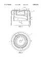
- FIG. 1is a side view of the components of a two-piece dispensing closure of this invention showing the outer cap positioned above the fitment, which is shown above the neck of a bottle for receiving the dispensing closure.
- FIG. 2is a perspective view of the neck of the bottle of FIG. 1.
- FIG. 3is a top view of the fitment for a dispensing closure of this invention.
- FIG. 4is a vertical cross-sectional view through the fitment of FIG. 3, taken along line 4--4 in FIG. 3.
- FIG. 5is a vertical cross-sectional view through the cap for a dispensing closure of this invention.
- FIG. 5As a greatly enlarged fragmentary view of a portion of the top wall of the cap, identified as 5A and FIG. 5.
- FIG. 6is a bottom view of the cap of FIG. 5.
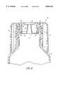
- FIG. 7is a cross-sectional view through a dispensing closure of this invention on a bottle and showing the closure in the open position.
- FIG. 8is a cross-sectional view similar to FIG. 7, except showing the closure in the closed position.
- a two-piece dispensing closure of this inventionis designed for use on containers for products that are not pressurized.
- the contents of the containersare typically liquid or semi-liquid products, which can be dispensed by inverting the bottle.
- the bottlemay be squeezed to expel the product through the dispensing closure in its open position.
- the bottleis preferably flexible plastic to permit such squeezing, but could also be glass or metal if the product is sufficiently low in viscosity to flow from the bottle without being expelled by squeezing the bottle.
- a preferred embodiment of a two-piece dispensing closureis shown as including a plastic outer cap 10 and a plastic fitment 12 for closing a container neck 14.
- the cap 10is preferably injection or compression molded and has a plurality of vertical serrations on ribs 16 in its outer skirt 18 for facilitating gripping of the cap to twist it between its closed and open positions on the bottle.
- the skirt 18preferably has diametrically opposed unserrated half moons or other markings on it to indicate where finger pressure should be applied to squeeze the cap as is explained below.
- the fitment 12is preferably injection molded and is dimensioned to fit into and be retained in the mouth opening of the bottle 14.
- the outside diameter of the fitmentis preferably greater than the inside diameter of the mouth opening to provide an interference fit therebetween.
- the interference fitcan also be enhanced by a bead, not shown, around the outside surface of the fitment.
- the fitment 12has an outer wall 26, an outwardly projecting flange 30 around the top of the outer wall, and a center post as best seen in FIGS. 3 and 4.
- the bottle neck 14is preferably cylindrical and has an inclined thread 20 or lugs on its outer cylindrical surface to engage a thread or lugs in the outer cap 10 as is described below.
- the bottle neckmay be inclined to vertical for convenience of pouring, or may be vertical as is more conventional.
- the bottle neck 14preferably has two teeth 22 on it for engaging diametrically opposed teeth on the inside of the cap 10 and at least one stop member 24 on the neck above the teeth 22 for engaging stop members on the inside of the cap as is also described below.
- the fitment 12 memberis more fully illustrated in FIGS. 3 and 4 as including an outer wall 26, a bottom wall 28, an outwardly projecting flange 30 around the top of the wall 26, a center post 32 projecting upwardly from the bottom wall 28, an annular sealing rim 34 projecting upwardly from the bottom wall adjacent its juncture with the outer wall, and an annular inwardly projecting rim 36 on the inside surface of the outer wall 26 above the top of the sealing rim 34.
- the outer wall 26may include an upwardly, outwardly include step or shoulder 27 at about the midpoint in the wall to help retain the fitment in a bottle mouth.
- the sealing wall 34, outer wall 26 and bottom wall 28cooperate to form an annular channel 31 around the bottom of the fitment 12.
- the bottom wall 28further has a plurality of flow apertures 29 though it in the channel 31 between the sealing rim 34 and the outer wall 26. Each aperture 29 preferably extends for about 70-80° around the fitment. The apertures 29 are separated bridges 37 between them.
- the center post 32 in the fitment 12is preferably hollow, to conserve on material, but could be solid.
- the post 32preferably has a cylindrical top portion 33 and tapers slightly outwardly toward its bottom and the bottom wall 28.
- the top corner of the post 32may optionally have a 45° bias on it around its perimeter to help guide the post into an aperture 40 in the top of the cap 12 (FIGS. 5 and 6).
- the top corner of the post 32may alternatively be rounded or have other angles on the bias.
- the outer cap 10is more fully illustrated in FIGS. 5 and 6 as including a cylindrical outer wall/skirt 18, a top wall 38 having a central aperture 40 in it, a cylindrical intermediate wall 42 having an internal thread 43 and two diametrically opposed stop members 50 on its inner surface, and cylindrical sealing wall 44 between the intermediate wall 42 and the aperture 40.
- the sealing wall 44has a downwardly and outwardly projecting sealing lip 48 on its bottom terminal edge.
- the top wall 38preferably has a downwardly projecting annular bead 39 on it for sealing against the top of the flange 30 on fitment 12 as is described below.
- the top wall 38preferably has a recessed central portion 41 with the aperture 40 located in its center.
- the recessed portion 41is flexible to help enhance the seal between the aperture 40 and the post 32 on the fitment 12 as is explained below.
- the aperture 40may have a generally frustoconical lower surface 47 which is slightly larger than the top of the post 32, an annular sealing bead 45 which is slightly smaller than the top of the post, and an upper diameter 49 which is also larger than the top of the post.
- the outer wall 18 of the cap 12preferably has two inwardly directed diametrically opposed teeth 46 on it for engaging the teeth 22 on the bottle 14 (FIG. 1).
- the teeth 22 on the bottle and teeth 46 on the skirtoperate to make the cap 10 child resistant.
- the skirt 18 of the cap 10must be squeezed on opposite sides between the teeth 46 to disengage the teeth 46 on the cap 10 from the teeth 22 on the bottle 14 and permit twisting or rotation of the cap on the bottle.
- Marks, such as the unserrated half moons 19are provided on the skirt 18 to identify where the skirt 18 should be squeezed. Squeezing the cap 12 at such marks flexs the skirt 18 into an elliptical shape to release the teeth 22 on the cap from the teeth 22 on the bottle neck.
- the thread 43 on the intermediate wall 42engages the thread 20 on the bottle neck 14 and causes the cap 10 to move up and down on the bottle neck when the cap is rotated or twisted on the bottle neck.
- the dispensing closure of this inventionis not designed to be removed from the bottle neck 14.
- the outer cap 10preferably has two integral stop members 50 projecting downwardly from the intermediate wall 42 to engage stop members or lugs 24 on the bottle neck 14 to limit twisting of the cap 10 on the bottle neck 14 to about a one-quarter turn (90°).
- the stop members 24 and 50 and threads 20 and 43 on the bottle neck 14 and cap 12are dimensioned and positioned such that the stop members will engage and stop further twisting of the cap after it has been twisted about 90° counterclockwise from the closed position of the cap on the bottle.
- FIG. 7shows a dispensing closure 10 of this invention as a bottle neck 14 with the closure in the open position.
- the fitment 12is secured in the bottle neck 14, and the outer cap 10 is secured on the bottle neck over the fitment and is in a raised position on the neck.
- the sealing lip 48 on the cap 10is seated against the underside of rim 36 on the fitment 12 to prevent product from flowing between the sealing wall 44 of the cap and the outer wall of the fitment.
- the arrowsshow the flow of product from the bottle and through the dispensing closure.
- the packageis shown in the upright position instead of the inverted position for product flow and dispensing by gravity and/or squeezing of the bottle. After product has been dispensed, the package is returned to the upright position, and most of the product that may remain in the fitment 12 can drain through the apertures 29 back into the bottle.
- FIG. 8is similar to FIG. 7 except the dispensing closure is shown in the closed position with the outer cap 10 twisted to its closed/down position on the bottle neck 14.
- the top of the center post 32 on the fitment 12is seated in the aperture 40 in the top wall 38 of the outer cap 10, and the sealing lip 48 on sealing wall 44 on the cap 10 is sealingly engaged in the channel in the fitment to close/seal the holes 29 through the bottom wall 28 of the fitment.
- the fitment 12 and cap 10are sized so that the post 32 will enter the aperture 40 in the cap and cause the flexible recessed portion 41 (FIG. 7) in the top wall of the cap to flex upwardly.
- This upward flexingcauses the sealing bead 45 in the aperture 40 to tightly seal with the cylindrical top portion 33 of the post 32.
- One sealis between the post 32 and top wall 38, and the other seals are between the sealing lip 48 and the bottom of the channel 31 and between the annular bead 39 on the undersurface of the top wall 38 of the cap 10 and the top surface of the flange 30 on the fitment 12.
- the skirt 18 of cap 10is squeezed on opposite sides at the unserrated half moons 19 to release teeth 46 from engagement with the teeth 22 on the bottle, and the cap is rotated or twisted about one-quarter turn counterclockwise. At this point, further twisting of the cap 10 on the bottle neck 14 is resisted/prevented by engagement of the stop members 50 on the cap with the stop members 46 on the bottle. The one-quarter twist of the cap 10 raises the cap on the bottle neck 14 to the open position shown in FIG. 6.
Landscapes
- Engineering & Computer Science (AREA)
- Mechanical Engineering (AREA)
- Closures For Containers (AREA)
Abstract
Description
Claims (12)
Priority Applications (1)
| Application Number | Priority Date | Filing Date | Title |
|---|---|---|---|
| US09/354,620US6062441A (en) | 1999-07-15 | 1999-07-15 | Two-piece dispensing closure |
Applications Claiming Priority (1)
| Application Number | Priority Date | Filing Date | Title |
|---|---|---|---|
| US09/354,620US6062441A (en) | 1999-07-15 | 1999-07-15 | Two-piece dispensing closure |
Publications (1)
| Publication Number | Publication Date |
|---|---|
| US6062441Atrue US6062441A (en) | 2000-05-16 |
Family
ID=23394186
Family Applications (1)
| Application Number | Title | Priority Date | Filing Date |
|---|---|---|---|
| US09/354,620Expired - LifetimeUS6062441A (en) | 1999-07-15 | 1999-07-15 | Two-piece dispensing closure |
Country Status (1)
| Country | Link |
|---|---|
| US (1) | US6062441A (en) |
Cited By (31)
| Publication number | Priority date | Publication date | Assignee | Title |
|---|---|---|---|---|
| US6334555B1 (en) | 2000-05-25 | 2002-01-01 | Seaquist Closures Foreign, Inc. | Fitment and resealable dispensing closure assembly for high-pressure sealing and bi-modal dispensing |
| WO2003004373A1 (en)* | 2001-07-03 | 2003-01-16 | Beeson & Sons Limited | Closure assembly with valve |
| US6520387B2 (en)* | 2000-06-07 | 2003-02-18 | Creative Edge Design Group Ltd. | Vent and pour cap |
| US20030178443A1 (en)* | 2002-03-21 | 2003-09-25 | Oeyvind Pedersen | Container and container support |
| US6669063B1 (en)* | 1998-11-03 | 2003-12-30 | Pechiney | Method for irreversibly fixing a cap on a container head enabling a limited rotation of said cap on said head |
| US20050184092A1 (en)* | 2004-02-20 | 2005-08-25 | Illuzzi Louis M. | Container dispenser device for separated flowable contents |
| US7055709B1 (en) | 2003-03-31 | 2006-06-06 | Theodore Esau | Receptacle cap for pills and other articles |
| RU2299844C2 (en)* | 2001-07-03 | 2007-05-27 | Бисан Энд Санз Лимитед | Sealing unit with valve |
| US7635071B1 (en) | 2006-08-09 | 2009-12-22 | Rexam Closures And Containers Inc. | Double shell dispensing closure with a reverse tapered drop lug |
| US7648051B1 (en)* | 2006-08-09 | 2010-01-19 | Rexam Closures And Containers Inc. | Double shell dispensing closure with a reverse tapered drop lug |
| US20110114595A1 (en)* | 2009-11-16 | 2011-05-19 | Heiberger Robert A | Pour Cap For Fluid Containers Having Open Or Closed Position Communication Structure And Low Temperature Sealing Gasket |
| WO2011149764A1 (en)* | 2010-05-24 | 2011-12-01 | The Clorox Company | Handled bottle |
| US20120160882A1 (en)* | 2010-12-22 | 2012-06-28 | Lumson S.P.A. | Device For Dispensing Fluid Substances, Particularly Creams |
| EP2432705A4 (en)* | 2009-05-19 | 2012-09-26 | Rev 8 Inc | OUTLET CAP FOR FLUID CONTAINER |
| US20130175273A1 (en)* | 2011-07-04 | 2013-07-11 | Obrist Closures Switzerland Gmbh | Closure |
| US20130186918A1 (en)* | 2010-05-25 | 2013-07-25 | Gabi Concepts Ltd. | Reusable beverage container with flexible spout |
| USD687665S1 (en) | 2012-04-16 | 2013-08-13 | Clay D. Nagel | Water jug with an insulated cover |
| US20130263424A1 (en)* | 2010-05-12 | 2013-10-10 | James Giocastro | Dual compartment dispenser |
| US20150367997A1 (en)* | 2014-06-18 | 2015-12-24 | Xiamen Bonpack Plastic Products Co., Ltd. | Switching structure capable of changing a discharging amount of a soft tube package |
| JP2019189323A (en)* | 2018-04-27 | 2019-10-31 | 株式会社吉野工業所 | Squeeze container with metering plug |
| USD871905S1 (en) | 2015-05-11 | 2020-01-07 | Silgan White Cap LLC | Closure |
| USD875525S1 (en) | 2017-03-29 | 2020-02-18 | Szent Co. | Bottle ring |
| USD876236S1 (en) | 2017-03-29 | 2020-02-25 | Szent Co. | Bottle ring |
| USD885906S1 (en)* | 2017-03-31 | 2020-06-02 | Szent Bev Co. | Bottle cap |
| US10744223B2 (en) | 2011-03-25 | 2020-08-18 | Szent Co. | Scented material compositions and articles for use with food and beverage |
| US10864293B2 (en) | 2011-03-25 | 2020-12-15 | Szent Co. | Scented attachment for containers |
| US11097877B2 (en) | 2018-05-31 | 2021-08-24 | Szent Co. | Scent delivery and preservation systems and methods for beverage containers |
| US20220041352A1 (en)* | 2020-08-07 | 2022-02-10 | Illinois Tool Works Inc. | Pressure Relief Assemblies and Methods |
| US11312528B2 (en) | 2019-10-07 | 2022-04-26 | Szent Co. | Scented attachments for beverage cartons |
| USD950384S1 (en) | 2018-05-16 | 2022-05-03 | Szent Co. | Bottle |
| USD1056710S1 (en)* | 2022-02-23 | 2025-01-07 | Beyond Plastic LLC | Shampoo bottle cap |
Citations (9)
| Publication number | Priority date | Publication date | Assignee | Title |
|---|---|---|---|---|
| US3058631A (en)* | 1959-02-17 | 1962-10-16 | Hitte Rodolphe Valery De La | Container closures |
| US3578223A (en)* | 1968-08-27 | 1971-05-11 | Monsanto Co | Container with closure |
| US4867354A (en)* | 1988-08-18 | 1989-09-19 | Schreiber Alexander R | Dispensing cap with means for controlled flow rate and multiple seals |
| US4946080A (en)* | 1988-04-13 | 1990-08-07 | Colgate-Palmolive Company | Fluid container with dosage assembly |
| US5044403A (en)* | 1990-10-03 | 1991-09-03 | Chen Chung F | Dirt and moisture sealing pipe plug for sealing different size pipe |
| US5275338A (en)* | 1991-04-23 | 1994-01-04 | Supermatic Kunststoff Ag | Device for spraying or atomizing a liquid |
| US5305932A (en)* | 1993-04-19 | 1994-04-26 | Seda International Plastics | Permanent snap-on, twist-open cap and container |
| WO1997039961A1 (en)* | 1996-04-19 | 1997-10-30 | Defi International | Dispensing closure with retracting end for container |
| US5715977A (en)* | 1995-01-10 | 1998-02-10 | Axia Cap | Container top including a ring provided with a distribution capsule having a partially unscrewable cap |
- 1999
- 1999-07-15USUS09/354,620patent/US6062441A/ennot_activeExpired - Lifetime
Patent Citations (10)
| Publication number | Priority date | Publication date | Assignee | Title |
|---|---|---|---|---|
| US3058631A (en)* | 1959-02-17 | 1962-10-16 | Hitte Rodolphe Valery De La | Container closures |
| US3578223A (en)* | 1968-08-27 | 1971-05-11 | Monsanto Co | Container with closure |
| US4946080A (en)* | 1988-04-13 | 1990-08-07 | Colgate-Palmolive Company | Fluid container with dosage assembly |
| US4867354A (en)* | 1988-08-18 | 1989-09-19 | Schreiber Alexander R | Dispensing cap with means for controlled flow rate and multiple seals |
| US5044403A (en)* | 1990-10-03 | 1991-09-03 | Chen Chung F | Dirt and moisture sealing pipe plug for sealing different size pipe |
| US5275338A (en)* | 1991-04-23 | 1994-01-04 | Supermatic Kunststoff Ag | Device for spraying or atomizing a liquid |
| US5305932A (en)* | 1993-04-19 | 1994-04-26 | Seda International Plastics | Permanent snap-on, twist-open cap and container |
| US5715977A (en)* | 1995-01-10 | 1998-02-10 | Axia Cap | Container top including a ring provided with a distribution capsule having a partially unscrewable cap |
| WO1997039961A1 (en)* | 1996-04-19 | 1997-10-30 | Defi International | Dispensing closure with retracting end for container |
| US5947331A (en)* | 1996-04-19 | 1999-09-07 | Defi International | Dispensing closure with retracting end for containers |
Cited By (54)
| Publication number | Priority date | Publication date | Assignee | Title |
|---|---|---|---|---|
| US6669063B1 (en)* | 1998-11-03 | 2003-12-30 | Pechiney | Method for irreversibly fixing a cap on a container head enabling a limited rotation of said cap on said head |
| US6334555B1 (en) | 2000-05-25 | 2002-01-01 | Seaquist Closures Foreign, Inc. | Fitment and resealable dispensing closure assembly for high-pressure sealing and bi-modal dispensing |
| US7021506B2 (en)* | 2000-06-07 | 2006-04-04 | Creative Edge Design Group, Ltd. | Vent and pour cap |
| US20030218032A1 (en)* | 2000-06-07 | 2003-11-27 | Creative Edge Design Group, Ltd. | Vent and pour cap |
| US6520387B2 (en)* | 2000-06-07 | 2003-02-18 | Creative Edge Design Group Ltd. | Vent and pour cap |
| RU2299844C2 (en)* | 2001-07-03 | 2007-05-27 | Бисан Энд Санз Лимитед | Sealing unit with valve |
| US20040232167A1 (en)* | 2001-07-03 | 2004-11-25 | King Roger Milner | Closure ssembly with valve |
| WO2003004373A1 (en)* | 2001-07-03 | 2003-01-16 | Beeson & Sons Limited | Closure assembly with valve |
| CN100384698C (en)* | 2001-07-03 | 2008-04-30 | 比森父子有限公司 | Cover assembly with valve |
| US7331491B2 (en)* | 2001-07-03 | 2008-02-19 | Roger Milner King | Closure assembly with valve |
| US6808090B2 (en) | 2002-03-21 | 2004-10-26 | Oeyvind Pedersen | Container and container support |
| US20030178443A1 (en)* | 2002-03-21 | 2003-09-25 | Oeyvind Pedersen | Container and container support |
| US7055709B1 (en) | 2003-03-31 | 2006-06-06 | Theodore Esau | Receptacle cap for pills and other articles |
| US7000804B2 (en) | 2004-02-20 | 2006-02-21 | Louis Illuzzi | Container dispenser device for separated flowable contents |
| US20050184092A1 (en)* | 2004-02-20 | 2005-08-25 | Illuzzi Louis M. | Container dispenser device for separated flowable contents |
| US7635071B1 (en) | 2006-08-09 | 2009-12-22 | Rexam Closures And Containers Inc. | Double shell dispensing closure with a reverse tapered drop lug |
| US7648051B1 (en)* | 2006-08-09 | 2010-01-19 | Rexam Closures And Containers Inc. | Double shell dispensing closure with a reverse tapered drop lug |
| EP2432705A4 (en)* | 2009-05-19 | 2012-09-26 | Rev 8 Inc | OUTLET CAP FOR FLUID CONTAINER |
| US20110114595A1 (en)* | 2009-11-16 | 2011-05-19 | Heiberger Robert A | Pour Cap For Fluid Containers Having Open Or Closed Position Communication Structure And Low Temperature Sealing Gasket |
| US8584877B2 (en) | 2009-11-16 | 2013-11-19 | Rev 8 Inc. | Pour cap for fluid containers having open or closed position communication structure with sound and visual features |
| US8915371B2 (en)* | 2010-05-12 | 2014-12-23 | James Giocastro | Dual compartment dispenser |
| US20130263424A1 (en)* | 2010-05-12 | 2013-10-10 | James Giocastro | Dual compartment dispenser |
| WO2011149764A1 (en)* | 2010-05-24 | 2011-12-01 | The Clorox Company | Handled bottle |
| US20130186918A1 (en)* | 2010-05-25 | 2013-07-25 | Gabi Concepts Ltd. | Reusable beverage container with flexible spout |
| US8613378B2 (en)* | 2010-12-22 | 2013-12-24 | Lumson S.P.A. | Axially stationary plug with one-way rotation |
| US20120160882A1 (en)* | 2010-12-22 | 2012-06-28 | Lumson S.P.A. | Device For Dispensing Fluid Substances, Particularly Creams |
| US12138370B2 (en) | 2011-03-25 | 2024-11-12 | Szent Co. | Scented attachment for containers |
| US10744223B2 (en) | 2011-03-25 | 2020-08-18 | Szent Co. | Scented material compositions and articles for use with food and beverage |
| US11389557B2 (en) | 2011-03-25 | 2022-07-19 | Szent Co. | Scented material compositions and articles for use with food and beverage |
| US11357881B2 (en) | 2011-03-25 | 2022-06-14 | Szent Co. | Scented attachment for containers |
| US10864293B2 (en) | 2011-03-25 | 2020-12-15 | Szent Co. | Scented attachment for containers |
| US20130175273A1 (en)* | 2011-07-04 | 2013-07-11 | Obrist Closures Switzerland Gmbh | Closure |
| USD687665S1 (en) | 2012-04-16 | 2013-08-13 | Clay D. Nagel | Water jug with an insulated cover |
| US20150367997A1 (en)* | 2014-06-18 | 2015-12-24 | Xiamen Bonpack Plastic Products Co., Ltd. | Switching structure capable of changing a discharging amount of a soft tube package |
| USD871905S1 (en) | 2015-05-11 | 2020-01-07 | Silgan White Cap LLC | Closure |
| USD934074S1 (en) | 2015-05-11 | 2021-10-26 | Silgan White Cap LLC | Closure |
| USD1042132S1 (en) | 2015-05-11 | 2024-09-17 | Silgan White Cap LLC | Closure |
| USD993769S1 (en) | 2015-05-11 | 2023-08-01 | Silgan White Cap LLC | Closure |
| USD876236S1 (en) | 2017-03-29 | 2020-02-25 | Szent Co. | Bottle ring |
| USD931105S1 (en) | 2017-03-29 | 2021-09-21 | Szent Co. | Bottle ring with bottle |
| USD875525S1 (en) | 2017-03-29 | 2020-02-18 | Szent Co. | Bottle ring |
| USD885906S1 (en)* | 2017-03-31 | 2020-06-02 | Szent Bev Co. | Bottle cap |
| JP2019189323A (en)* | 2018-04-27 | 2019-10-31 | 株式会社吉野工業所 | Squeeze container with metering plug |
| JP7030009B2 (en) | 2018-04-27 | 2022-03-04 | 株式会社吉野工業所 | Squeeze container with weighing tap |
| USD950384S1 (en) | 2018-05-16 | 2022-05-03 | Szent Co. | Bottle |
| US11613415B2 (en) | 2018-05-31 | 2023-03-28 | Szent Co. | Scent delivery and preservation systems and methods for beverage containers |
| US11097877B2 (en) | 2018-05-31 | 2021-08-24 | Szent Co. | Scent delivery and preservation systems and methods for beverage containers |
| US12202662B2 (en) | 2018-05-31 | 2025-01-21 | Szent Co. | Scent delivery and preservation systems and methods for beverage containers |
| US11312528B2 (en) | 2019-10-07 | 2022-04-26 | Szent Co. | Scented attachments for beverage cartons |
| US11724853B2 (en) | 2019-10-07 | 2023-08-15 | Szent Co. | Scented attachments for beverage cartons |
| US11628991B2 (en)* | 2020-08-07 | 2023-04-18 | Illinois Tool Works Inc. | Pressure relief assemblies and methods |
| US11964803B2 (en) | 2020-08-07 | 2024-04-23 | Illinois Tool Works Inc. | Pressure relief assemblies and methods |
| US20220041352A1 (en)* | 2020-08-07 | 2022-02-10 | Illinois Tool Works Inc. | Pressure Relief Assemblies and Methods |
| USD1056710S1 (en)* | 2022-02-23 | 2025-01-07 | Beyond Plastic LLC | Shampoo bottle cap |
Similar Documents
| Publication | Publication Date | Title |
|---|---|---|
| US6062441A (en) | Two-piece dispensing closure | |
| AU2002320484B2 (en) | Twist Openable Dispensing Closure Accommodating Optional Liner Puncture Feature | |
| US6571994B1 (en) | Closure having rotatable spout and axially movable stem | |
| US4638916A (en) | Closure with snap-type hinge cap | |
| US6334555B1 (en) | Fitment and resealable dispensing closure assembly for high-pressure sealing and bi-modal dispensing | |
| US4635823A (en) | Dispensing closure construction | |
| CN101573273B (en) | Dispensing caps for beverage containers | |
| US6871764B2 (en) | Beverage closure with open/close spout and protected seal surfaces | |
| US20100140266A1 (en) | Dispensing closure with hinged lid | |
| AU2002320484A1 (en) | Twist Openable Dispensing Closure Accommodating Optional Liner Puncture Feature | |
| US4383623A (en) | Dispensing closure with stationary axial plug | |
| EP3842358B1 (en) | Capping device intended to be fixed to a neck of a container | |
| US8931243B2 (en) | Hot-fill method | |
| US20050269373A1 (en) | Cover for dispensing closure with pressure actuated valve | |
| EP3887278B1 (en) | A spouted pouch provided with a closure device | |
| US20100012687A1 (en) | Internal container bore mount fitment | |
| MXPA02004403A (en) | Improved pourer and incorporated pourer cap. | |
| US3407976A (en) | Container with plural pour spouts and frangible closure | |
| US3285453A (en) | Closure cap device | |
| US20090120899A1 (en) | Flip top container closure | |
| EP0701523B1 (en) | Clog-resistant toggle disk closure | |
| EP1332977A1 (en) | Dispensing closure and package incorporating same | |
| US3405850A (en) | Screw actuated toggle valve dispensing cap | |
| US6056161A (en) | Push-pull dispenser | |
| JP3221267B2 (en) | Sealing cap |
Legal Events
| Date | Code | Title | Description |
|---|---|---|---|
| AS | Assignment | Owner name:RXI PLASTICS, INC., WEST VIRGINIA Free format text:ASSIGNMENT OF ASSIGNORS INTEREST;ASSIGNORS:MENGEU, GARY LEE;HAND, SCOTT ALAN;REEL/FRAME:010123/0922 Effective date:19990706 | |
| STCF | Information on status: patent grant | Free format text:PATENTED CASE | |
| AS | Assignment | Owner name:BANKERS TRUST COMPANY, NEW YORK Free format text:SECURITY INTEREST;ASSIGNOR:RXI PLASTICS, INC. A CORPORATION OF DELAWARE;REEL/FRAME:011314/0420 Effective date:20001005 | |
| AS | Assignment | Owner name:DEUTSCHE BANK TRUST COMPANY AMERICAS, NEW YORK Free format text:SECURITY AGREEMENT;ASSIGNOR:RXI PLASTICS, INC.;REEL/FRAME:013146/0773 Effective date:20020628 | |
| FPAY | Fee payment | Year of fee payment:4 | |
| AS | Assignment | Owner name:RXI PLASTICS, INC., CONNECTICUT Free format text:PATENT RELEASE;ASSIGNOR:DEUTSCHE BANK TRUST COMPANY AMERICAS, AS COLLATERAL AGENT;REEL/FRAME:016460/0938 Effective date:20050630 | |
| FPAY | Fee payment | Year of fee payment:8 | |
| FPAY | Fee payment | Year of fee payment:12 |