US6062372A - Post-folder diverting apparatus using parallel drives - Google Patents
Post-folder diverting apparatus using parallel drivesDownload PDFInfo
- Publication number
- US6062372A US6062372AUS08/914,313US91431397AUS6062372AUS 6062372 AUS6062372 AUS 6062372AUS 91431397 AUS91431397 AUS 91431397AUS 6062372 AUS6062372 AUS 6062372A
- Authority
- US
- United States
- Prior art keywords
- gripper
- conveyor
- cable
- recess
- conveyor cable
- Prior art date
- Legal status (The legal status is an assumption and is not a legal conclusion. Google has not performed a legal analysis and makes no representation as to the accuracy of the status listed.)
- Expired - Lifetime
Links
Images


Classifications
- B—PERFORMING OPERATIONS; TRANSPORTING
- B65—CONVEYING; PACKING; STORING; HANDLING THIN OR FILAMENTARY MATERIAL
- B65H—HANDLING THIN OR FILAMENTARY MATERIAL, e.g. SHEETS, WEBS, CABLES
- B65H29/00—Delivering or advancing articles from machines; Advancing articles to or into piles
- B65H29/003—Delivering or advancing articles from machines; Advancing articles to or into piles by grippers
- B65H29/005—Delivering or advancing articles from machines; Advancing articles to or into piles by grippers by chains or bands having mechanical grippers engaging the side edges of articles, e.g. newspaper conveyors
- B—PERFORMING OPERATIONS; TRANSPORTING
- B65—CONVEYING; PACKING; STORING; HANDLING THIN OR FILAMENTARY MATERIAL
- B65H—HANDLING THIN OR FILAMENTARY MATERIAL, e.g. SHEETS, WEBS, CABLES
- B65H2301/00—Handling processes for sheets or webs
- B65H2301/30—Orientation, displacement, position of the handled material
- B65H2301/33—Modifying, selecting, changing orientation
- B—PERFORMING OPERATIONS; TRANSPORTING
- B65—CONVEYING; PACKING; STORING; HANDLING THIN OR FILAMENTARY MATERIAL
- B65H—HANDLING THIN OR FILAMENTARY MATERIAL, e.g. SHEETS, WEBS, CABLES
- B65H2301/00—Handling processes for sheets or webs
- B65H2301/40—Type of handling process
- B65H2301/44—Moving, forwarding, guiding material
- B65H2301/445—Moving, forwarding, guiding material stream of articles separated from each other
- B65H2301/4451—Moving, forwarding, guiding material stream of articles separated from each other forming a stream or streams of separated articles
- B—PERFORMING OPERATIONS; TRANSPORTING
- B65—CONVEYING; PACKING; STORING; HANDLING THIN OR FILAMENTARY MATERIAL
- B65H—HANDLING THIN OR FILAMENTARY MATERIAL, e.g. SHEETS, WEBS, CABLES
- B65H2301/00—Handling processes for sheets or webs
- B65H2301/40—Type of handling process
- B65H2301/44—Moving, forwarding, guiding material
- B65H2301/445—Moving, forwarding, guiding material stream of articles separated from each other
- B65H2301/4455—Diverting a main stream into part streams
- B65H2301/44552—Diverting a main stream into part streams by alternatively directing articles following each other to appropriate part stream
- B—PERFORMING OPERATIONS; TRANSPORTING
- B65—CONVEYING; PACKING; STORING; HANDLING THIN OR FILAMENTARY MATERIAL
- B65H—HANDLING THIN OR FILAMENTARY MATERIAL, e.g. SHEETS, WEBS, CABLES
- B65H2405/00—Parts for holding the handled material
- B65H2405/50—Gripping means
- B65H2405/53—Rotary gripping arms
- B65H2405/531—Rotary gripping arms with relative movement of the arms relatively to the axis of rotation during rotation
Definitions
- the present inventionrelates to an apparatus for separating two or more versions of flat products, especially printed signatures, into separate secondary product streams from a single imbricated product stream.
- a common step in producing printed products using web offset printing press technologyincludes forming, folding and cutting a continuous paper web to form printed products, referred to as signatures.
- the signaturesexit from a folder apparatus after being processed by, for example, a fan wheel or deceleration device, which slows the speed of the signatures relative to the speed of the web.
- a fan wheel or deceleration deviceAn example of such a deceleration device is described, for example, in U.S. Pat. No. 5,452,866.
- the signaturesgenerally exit the folder for further processing on a conveyor in imbricated (e.g., shingled) fashion and in ordered series. It is important to maintain the ordering, or registration, of the signatures because the further processing typically involves combining multiple signatures, by binding or other means, to create a final product.
- the image to be transferred onto the paper webis typically etched onto a printing plate mounted on a print cylinder.
- the ink imageis transferred from the plate cylinder onto a blanket cylinder which then transfers the image onto the paper web.
- the width of the printed imageis less than one half the circumference of the print cylinder, multiple images can be printed with one rotation of the print cylinder. Accordingly, two separate products can be printed simultaneously onto a single web, which results in signatures for the first product exiting from the folder nested between signatures for the second product in a single imbricated stream.
- U.S. Pat. No. 4,550,822describes an apparatus for transporting flat products, especially printed products arriving in an imbricated formation.
- Each gripping unit of the apparatuscomprises a stationary clamping jaw, a pivotable clamping jaw and a plate shaped stop.
- the pivotable clamping jawis pivoted against the action of a closing spring by a cam structure or the like.
- the productsare first accelerated and then pushed into the open gripper mouth until abutting the stop. Thereby, the printed products are aligned at the region of their leading edges. At their trailing edges the printed products remain under the conveying action of the belt conveyor at least until the gripper units are closed.
- U.S. Pat. No. 4,072,228describes an apparatus for evening an imbricated stream of printed products.
- This apparatuscomprises a number of revolving entrainment members designed to engage the printed products and which are in a drag connection with one another.
- the entrainment membersare driven by a thrust drive at the beginning of their conveying action path and by a traction drive at the end thereof. After the entrainment members engage the printed products, the thrust and traction drives cause a change in the spacing of the entrainment members and, consequently, in the spacing of the products.
- U.S. Pat. No. 3,809,214describes a turning conveyor for flat structures, especially printed products.
- This turning conveyorencompasses a plurality of entrainment members which move along with the flat structures. Each entrainment member can be brought into engagement with a respective one of the flat structures.
- the entrainment membersare controlled such that, at least at the time they are in engagement with a flat structure, they turn relative to the direction of movement of the main conveyor, thereby turning the flat structures during the course of conveying same about an axis which is perpendicular to the flat structures.
- Another known method of separating a stream of productsuses a gripper conveyor system and a vacuum belt, such as are commonly used with newspaper gripper conveyor systems.
- the gripper blocksare connected to one another, similar to links in a chain, and the gripper blocks form the conveyor cable.
- a gripper conveyordrags a stream of products over a vacuum belt traveling slower than the conveyor and releases every second flat product from the gripper conveyor onto the vacuum belt.
- This method of separating a stream of productshas the disadvantage that it does not allow positive control of the signatures while separating them from a primary product stream to secondary product streams. More particularly, this method relies on the attractive force between the vacuum belt and the trailing edge of the released signature to maintain orientation of the signature. This degree of control is insufficient at high speeds or when transporting light products.
- a further object of the present inventionis to perform the separating of the signatures while maintaining positive control of the flat structures as they exit the folder, thereby maintaining reliability at high speeds and with light products.
- an apparatuswhich controls each signature individually by gripping the signature as it is released from a folder in an imbricated stream and transporting the stream away from the folder.
- the grippers that control the signaturesare attached to gripper blocks which are in turn connected to one of two conveyor cables that travel in parallel paths for the first part of the signature transportation away from the folder.
- the gripper blocks according to the present inventionare not connected to adjoining gripper blocks but adjoining gripper blocks are separate and attached to one of two respective conveyor cables.
- the grippers that control the first set of signaturesare guided, for example, by a first conveyor cable and the grippers that control the second set of signatures are guided, for example, by a second conveyor cable.
- the two conveyor cablesfollow parallel paths and use the same track and signature guide structure until the point where the first set of signatures are diverted away from the first set of signatures.
- the second conveyor cablefollows a path that deviates from the path of the first conveyor cable. Accordingly, the path of the second set of signatures diverts from that of the first set of signatures until they are separated from the first set of signatures. After the signatures are separated, they are released by the grippers onto, for example, separate belt conveyors resulting in separate imbricated streams for transport to conventional post-processing equipment.
- the gripper elementsare rotated relative to the gripper block to provide each set of signatures in a folding edge leading presentation.
- FIG. 1shows a top view of gripper blocks attached to conveyor cables according to the present invention
- FIG. 2shows an expanded top view of first and second conveyor systems according to the present invention
- FIG. 3(a)shows a side view of the gripper blocks following a track and signature guide structure according to the present invention
- FIG. 3(b)shows an exemplary deceleration device delivering signatures to a gripper conveyor system according to the present invention
- FIG. 3(c)shows a side view of the exemplary deceleration device shown in FIG. 3(b);
- FIG. 4shows a perspective view of a first and second gripper block and the corresponding conveyor cables according to the present invention
- FIG. 5(a)shows a perspective view of one of the grippers in a conveyor system according to an embodiment of the present invention
- FIG. 5(b)shows a top view of one of the grippers according to an embodiment of the present invention
- FIG. 5(c)shows a perspective view of one of the grippers further showing a cut-away view of the detail of the rotation and clamping mechanism according to an embodiment of the present invention.
- FIG. 5(d)shows a perspective view of one of the grippers further showing a cut-away view of the detail of the rotation and clamping mechanism according to a second embodiment of the present invention
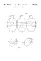
- FIG. 1shows two exemplary styles of gripper blocks according to the present invention arranged in parallel formation.
- a first gripper block 1is attached to a first conveyor cable 3 and to a first gripper element 5.
- a second gripper block 2is attached to a second conveyor cable 4 and to a second gripper element 6.
- the gripper elements 5, 6are known in the art and conventionally mounted to the respective gripper block 1, 2 via, for example, a bolted connection.
- the gripper blocks and gripper elementsare described here as separate units, however, the present invention also encompasses an embodiment in which gripper blocks and gripper elements are formed as a single unit.
- First gripper block 1has a first recess 17, for example generally cylindrical in shape, running through the gripper block to receive drive cable 3 to which it is attached.
- second gripper block 2has a first recess 18, also generally cylindrical in shape, running through the gripper block to receive drive cable 4 to which it is attached.
- Gripper blocks 1, 2 and conveyor cables 3, 4are respectively attached via, for example, a detente locking mechanism.
- conventional spherical detente mechanisms 13, 14 in gripper blocks 1, 2fit releasably and firmly around appropriately sized and spaced spheres attached to conveyor cables 3, 4, thereby maintaining the relative position of each of gripper blocks 1, 2 to their respective conveyor cable.
- FIG. 4shows a perspective view of a first gripper block 1 and a second gripper block 2 according to an embodiment of the present invention.
- each first gripper block 1contains a second recess 15 to allow conveyor cable 4 to pass through without contacting gripper block 1.
- each second gripper block 2contains a second recess 16 to allow conveyor cable 3 to pass through without contacting gripper block 2.
- Second recesses 15, 16 in respective gripper blocks 1, 2are sized and shaped so as to allow, for example, first gripper block 1 to divert to the left relative to the path of second conveyor cable 4, and to allow second gripper block 2 to divert to the right relative to the path of first conveyor cable 3.
- This constructionallows gripper blocks 1, 2 to follow a common, parallel path for part of the way and divert into separate paths for part of the way, thereby accomplishing the task of separating the two different signatures from a single imbricated stream, as described below.
- FIG. 2depicts an embodiment of the post-folder diverting apparatus according to the present invention in which the two conveyor cables 3, 4 diverge from a common parallel path to separate the single imbricated stream of signatures 7, 8 into two separate product streams.
- conveyor drive 9rotates in a clockwise direction thereby driving conveyor cable 3 along the path as indicated.
- conveyor drive 10also rotates in a clockwise direction driving conveyor cable 4 along the path as shown.
- Each gripper element 5is attached to a respective first gripper block 1 which in turn is attached to conveyor cable 3.
- numerous first gripper blockscan be attached to conveyor cable 3.
- each gripper element 6is attached to a respective second gripper block 2 which in turn is attached to conveyor cable 4.
- adjoining gripper blocks 1, 2 in the apparatus according to the present inventionare separated from one another and attached to respective conveyor cables 3, 4.
- each gripper element 5grips each first signature 7 and each gripper element 6 grips each second signature 8.
- FIG. 3(b)illustrates an exemplary embodiment of a deceleration device 100 handing-off signatures 7, 8 to respective gripper elements 5, 6.
- the deceleration device 100shown in side view in FIG. 3(c), can be used for slowing down the signatures 7, 8 being delivered from a folder as described in, for example, U.S. Pat. No. 5,452,866 which is hereby incorporated by reference.
- gripper blocks 1, 2are attached to respective conveyor cables 3, 4 and follow a path next to the deceleration device 100. By arranging the gripper blocks 1, 2 and conveyor cables 3, 4 to follow the path next to the deceleration device 100, the respective gripper elements 5, 6 can grab the signatures 7, 8 as the deceleration device 100 releases each respective signature 7, 8.
- the exemplary design of the gripper blocks according to the present invention shown in FIG. 4allows the separation of the gripper blocks 1, 2 and thus the signatures 7, 8.
- signatures 7, 8Upon reaching a predetermined position, for example, at the point where signatures 7, 8 are aligned directly above separate respective belt conveyors at, for example locations X and Y, signatures 7, 8 are released from grippers 5, 6 as they have become fully separated from each other and thereby form separated signatures 7, 8 for further processing such as, for example, binding.
- the paths of conveyor cables 3, 4rejoin as they guide gripper blocks 1, 2 and gripper elements 5, 6 back towards the folder.
- FIG. 2An additional feature of the post-folder diverting apparatus according to the present invention is depicted in FIG. 2.
- signatures 7, 8can be rotated relative to the gripper blocks 1, 2, thus enabling the signatures 7, 8 to be continuously oriented in a folded edge leading orientation.
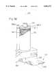
- FIGS. 5(a)-(d)show an exemplary gripper 5, 6 according to the present invention that can rotate relative to the gripper block in greater detail.
- the rotation axis 200extends perpendicular to the conveying direction 270, thus allowing the gripper head 150 to rotate.
- the rotational movement of gripper head 150extends, as shown, approximately 45 degrees through the given angle 25 as shown in FIG. 5(b), but can also be adjusted to accommodate other rotational positions, indicated by second alternate position 25'.
- FIG. 5(c)shows a cross-section through a portion of a gripper element 5, 6.
- the first actuating pin 130is linked with a moveable portion 230 of a product gripper head 150 via a rod 130.4.
- a stationary portion 220 of the product gripper head 150is mounted to the support 190.
- the moveable portion 230 of the gripper element 5, 6is moved downward releasing a product held between the stationary portion 220 and the moveable portion 230.
- a spring 130.3is pretensioned between an upper support 130.5 and a lower support 130.2, the upper support 130.5 mounted to the rod 130.4.
- a pretensioning devicesuch as a spring 140 is mounted for facilitating the rotational movement of the gripper head 150.
- a second actuating pin 1300is provided for actuating rotational movement of the gripper head 150 about the axis 200.
- a cocking mechanisme.g., a post appropriately mounted in the path of the gripper head 150
- the spring 140is held in tension by an actuation device (e.g., a tab holding one end of the spring 140).
- the second actuating pin 1300When the second actuating pin 1300 is subsequently pressed, it causes the actuating mechanism to release the spring 140 from tension and the gripper head gradually rotates counterclockwise along the angle 25 into the second (rotated) position as shown in FIG. 5(b).
- actuating mechanisms 340can be accomplished by actuating mechanisms 340 (not shown) in a variety of ways.
- rotation of the gripper head 150has been described above with respect to a spring actuated mechanism, it should be clear that other rotation mechanisms are also acceptable.
- rotation of the gripper head 150could be accomplished with conventional hydraulic or pneumatic mechanisms.
- an electrically controlled motorcould be used.
- the gripper head 150can be returned to the first position under the control of a pneumatic, hydraulic, or electrically controlled mechanism. Rotation from the second position to the first position could then be triggered, for example, by providing an additional actuating pin, or by toggling the actuating pin 1300.
- actuating pin 130is illustrated as opening the gripper 150 by means of a spring mechanism, it should be clear that a hydraulic or pneumatic mechanism, or any other suitable device, could also be used.
- the gripper mechanismhas gripper jaws designed, for example, to grasp a corner of a signature.
- gripper blocks without wheelsslide along the guide track such as by selecting the appropriate material for construction of the gripper blocks and/or the guide track so as to have a desired coefficient of friction, such as forming the gripper blocks 1, 2 from a self lubricating plastic or nylon.
Landscapes
- Engineering & Computer Science (AREA)
- Mechanical Engineering (AREA)
- Feeding Of Articles By Means Other Than Belts Or Rollers (AREA)
- Separation, Sorting, Adjustment, Or Bending Of Sheets To Be Conveyed (AREA)
Abstract
Description
Claims (10)
Priority Applications (3)
| Application Number | Priority Date | Filing Date | Title |
|---|---|---|---|
| US08/914,313US6062372A (en) | 1997-08-13 | 1997-08-13 | Post-folder diverting apparatus using parallel drives |
| DE59800749TDE59800749D1 (en) | 1997-08-13 | 1998-07-03 | Device for dividing copy streams behind a folder |
| EP98112325AEP0896942B1 (en) | 1997-08-13 | 1998-07-03 | Device for dividing signature streams behind a folding apparatus |
Applications Claiming Priority (1)
| Application Number | Priority Date | Filing Date | Title |
|---|---|---|---|
| US08/914,313US6062372A (en) | 1997-08-13 | 1997-08-13 | Post-folder diverting apparatus using parallel drives |
Publications (1)
| Publication Number | Publication Date |
|---|---|
| US6062372Atrue US6062372A (en) | 2000-05-16 |
Family
ID=25434183
Family Applications (1)
| Application Number | Title | Priority Date | Filing Date |
|---|---|---|---|
| US08/914,313Expired - LifetimeUS6062372A (en) | 1997-08-13 | 1997-08-13 | Post-folder diverting apparatus using parallel drives |
Country Status (3)
| Country | Link |
|---|---|
| US (1) | US6062372A (en) |
| EP (1) | EP0896942B1 (en) |
| DE (1) | DE59800749D1 (en) |
Cited By (8)
| Publication number | Priority date | Publication date | Assignee | Title |
|---|---|---|---|---|
| US6401903B1 (en)* | 1999-06-23 | 2002-06-11 | Ferag Ag | Method and device for removing sections from a stream of imbricated items |
| US20030015837A1 (en)* | 2001-07-18 | 2003-01-23 | Ferag Ag | Method and device for transforming a conveying stream of flat articles |
| US6581752B2 (en) | 2000-05-17 | 2003-06-24 | Ferag Ag | Method and device for splitting-up a stream of piece goods |
| WO2007045105A1 (en)* | 2005-07-29 | 2007-04-26 | Ferag Ag | Conveying system |
| US20100201066A1 (en)* | 2009-02-06 | 2010-08-12 | Goss International Americas, Inc. | Multiple delivery web conversion apparatus and method of producing and delivering variable printed products |
| US20100201058A1 (en)* | 2009-02-06 | 2010-08-12 | Goss International Americas, Inc. | Web conversion and collating apparatus and method |
| US20100201056A1 (en)* | 2009-02-06 | 2010-08-12 | Goss International Americas, Inc. | Single level web conversion apparatus and method |
| US20110219970A1 (en)* | 2009-02-06 | 2011-09-15 | Goss International Americas, Inc. | Adjustable delivery web conversion apparatus and method |
Families Citing this family (1)
| Publication number | Priority date | Publication date | Assignee | Title |
|---|---|---|---|---|
| US5992610A (en)* | 1997-08-15 | 1999-11-30 | Heidelberger Druckmashinen Ag | Method and device for producing a rotated stream with a corner gripper |
Citations (15)
| Publication number | Priority date | Publication date | Assignee | Title |
|---|---|---|---|---|
| US2325862A (en)* | 1941-04-07 | 1943-08-03 | Jepson Percy | Multiple loading track or conveyer for fruit or vegetables |
| US3339701A (en)* | 1966-10-03 | 1967-09-05 | R A Jones & Company Inc | Phase conversion conveyor system |
| US3390508A (en)* | 1964-08-25 | 1968-07-02 | Winkler Fallert & Co Maschf | Apparatus for the interlaced packaging of folded printed matter |
| US3635322A (en)* | 1970-02-24 | 1972-01-18 | Emhart Corp | Conveyor system for dividing a line of articles into several discrete lanes |
| US3809214A (en)* | 1971-09-14 | 1974-05-07 | Fehr & Reist Ag | Turning conveyor for flat structures, especially printed products |
| US4072228A (en)* | 1975-05-20 | 1978-02-07 | Ferag Ag | Apparatus for evening an imbricated stream of printed products |
| US4550822A (en)* | 1982-03-11 | 1985-11-05 | Ferag Ag | Apparatus for transporting flat products, especially printed products arriving in an imbricated formation |
| US4678172A (en)* | 1985-12-27 | 1987-07-07 | Custom-Bilt Machinery, Inc. | High speed on-line reshingling of printed products |
| EP0309702A1 (en)* | 1987-10-02 | 1989-04-05 | Ferag AG | Continuous conveyor for articles |
| EP0399188A2 (en)* | 1989-05-25 | 1990-11-28 | Am International Incorporated | Sheet material handling apparatus and method |
| EP0633212A1 (en)* | 1993-07-07 | 1995-01-11 | Ferag AG | Endless circulating transport device for unit load with individual transport elements |
| US5443254A (en)* | 1992-04-27 | 1995-08-22 | Ferag Ag | Active interface for an imbricated stream of printed products |
| US5452886A (en)* | 1993-08-09 | 1995-09-26 | Heidelberger Druckmaschinen Ag | Device for slowing down signatures in a folding machine |
| DE19621331A1 (en)* | 1995-07-20 | 1997-01-23 | Heidelberger Druckmasch Ag | Device for dividing a product stream |
| EP0819635A2 (en)* | 1996-07-18 | 1998-01-21 | Gämmerler, Hagen | Transport system with grippers |
- 1997
- 1997-08-13USUS08/914,313patent/US6062372A/ennot_activeExpired - Lifetime
- 1998
- 1998-07-03EPEP98112325Apatent/EP0896942B1/ennot_activeExpired - Lifetime
- 1998-07-03DEDE59800749Tpatent/DE59800749D1/ennot_activeExpired - Lifetime
Patent Citations (17)
| Publication number | Priority date | Publication date | Assignee | Title |
|---|---|---|---|---|
| US2325862A (en)* | 1941-04-07 | 1943-08-03 | Jepson Percy | Multiple loading track or conveyer for fruit or vegetables |
| US3390508A (en)* | 1964-08-25 | 1968-07-02 | Winkler Fallert & Co Maschf | Apparatus for the interlaced packaging of folded printed matter |
| US3339701A (en)* | 1966-10-03 | 1967-09-05 | R A Jones & Company Inc | Phase conversion conveyor system |
| US3635322A (en)* | 1970-02-24 | 1972-01-18 | Emhart Corp | Conveyor system for dividing a line of articles into several discrete lanes |
| US3809214A (en)* | 1971-09-14 | 1974-05-07 | Fehr & Reist Ag | Turning conveyor for flat structures, especially printed products |
| US4072228A (en)* | 1975-05-20 | 1978-02-07 | Ferag Ag | Apparatus for evening an imbricated stream of printed products |
| US4550822A (en)* | 1982-03-11 | 1985-11-05 | Ferag Ag | Apparatus for transporting flat products, especially printed products arriving in an imbricated formation |
| US4678172A (en)* | 1985-12-27 | 1987-07-07 | Custom-Bilt Machinery, Inc. | High speed on-line reshingling of printed products |
| EP0309702A1 (en)* | 1987-10-02 | 1989-04-05 | Ferag AG | Continuous conveyor for articles |
| EP0399188A2 (en)* | 1989-05-25 | 1990-11-28 | Am International Incorporated | Sheet material handling apparatus and method |
| US5007624A (en)* | 1989-05-25 | 1991-04-16 | Am International Incorporated | Sheet material handling apparatus and method |
| US5443254A (en)* | 1992-04-27 | 1995-08-22 | Ferag Ag | Active interface for an imbricated stream of printed products |
| EP0633212A1 (en)* | 1993-07-07 | 1995-01-11 | Ferag AG | Endless circulating transport device for unit load with individual transport elements |
| US5452886A (en)* | 1993-08-09 | 1995-09-26 | Heidelberger Druckmaschinen Ag | Device for slowing down signatures in a folding machine |
| US5560599A (en)* | 1993-08-09 | 1996-10-01 | Heidelberger Druckmaschinen Ag | Device for slowing down signatures in a folding machine |
| DE19621331A1 (en)* | 1995-07-20 | 1997-01-23 | Heidelberger Druckmasch Ag | Device for dividing a product stream |
| EP0819635A2 (en)* | 1996-07-18 | 1998-01-21 | Gämmerler, Hagen | Transport system with grippers |
Cited By (18)
| Publication number | Priority date | Publication date | Assignee | Title |
|---|---|---|---|---|
| US6401903B1 (en)* | 1999-06-23 | 2002-06-11 | Ferag Ag | Method and device for removing sections from a stream of imbricated items |
| US6581752B2 (en) | 2000-05-17 | 2003-06-24 | Ferag Ag | Method and device for splitting-up a stream of piece goods |
| US20030015837A1 (en)* | 2001-07-18 | 2003-01-23 | Ferag Ag | Method and device for transforming a conveying stream of flat articles |
| US6669192B2 (en)* | 2001-07-18 | 2003-12-30 | Ferag Ag | Method and device for transforming a conveying stream of flat articles |
| AU2006303798B2 (en)* | 2005-07-29 | 2011-08-25 | Ferag Ag | Conveying system |
| US7784602B2 (en) | 2005-07-29 | 2010-08-31 | Ferag Ag | Conveying system |
| WO2007045105A1 (en)* | 2005-07-29 | 2007-04-26 | Ferag Ag | Conveying system |
| US20080210521A1 (en)* | 2005-07-29 | 2008-09-04 | Ferag Ag | Conveying System |
| US8002257B2 (en) | 2009-02-06 | 2011-08-23 | Goss International Americas, Inc. | Web conversion and collating apparatus and method |
| US20100201056A1 (en)* | 2009-02-06 | 2010-08-12 | Goss International Americas, Inc. | Single level web conversion apparatus and method |
| WO2010090769A1 (en)* | 2009-02-06 | 2010-08-12 | Goss International Americas, Inc. | Web conversion and collating apparatus and method |
| US20100201058A1 (en)* | 2009-02-06 | 2010-08-12 | Goss International Americas, Inc. | Web conversion and collating apparatus and method |
| US20100201066A1 (en)* | 2009-02-06 | 2010-08-12 | Goss International Americas, Inc. | Multiple delivery web conversion apparatus and method of producing and delivering variable printed products |
| US20110219970A1 (en)* | 2009-02-06 | 2011-09-15 | Goss International Americas, Inc. | Adjustable delivery web conversion apparatus and method |
| US8020845B2 (en) | 2009-02-06 | 2011-09-20 | Goss International Americas, Inc. | Single level web conversion apparatus and method |
| US8020847B2 (en) | 2009-02-06 | 2011-09-20 | Goss International Americas, Inc. | Multiple delivery web conversion apparatus and method of producing and delivering variable printed products |
| US8104755B2 (en) | 2009-02-06 | 2012-01-31 | Goss International Americas, Inc. | Adjustable delivery web conversion apparatus and method |
| US8356809B2 (en) | 2009-02-06 | 2013-01-22 | Goss International Americas, Inc. | Adjustable delivery web conversion apparatus and method |
Also Published As
| Publication number | Publication date |
|---|---|
| EP0896942B1 (en) | 2001-05-23 |
| DE59800749D1 (en) | 2001-06-28 |
| EP0896942A2 (en) | 1999-02-17 |
| EP0896942A3 (en) | 1999-10-20 |
Similar Documents
| Publication | Publication Date | Title |
|---|---|---|
| US5975280A (en) | Device for transporting flat products to further processing units or delivery stations | |
| US4919027A (en) | Sheet diverting and delivery system | |
| DE4417178A1 (en) | Device for slowing down copies in a folder | |
| US6062372A (en) | Post-folder diverting apparatus using parallel drives | |
| DE19955819A1 (en) | Decceleration and guide device for folded paper sheets has main roller unit and pressure generating roller unit with projecting cam parts to slow-down sheets | |
| EP0754642B1 (en) | Method and device for delivering sheet-like products | |
| EP0323557B1 (en) | Device for transporting flat products, in particular printed products | |
| US5992610A (en) | Method and device for producing a rotated stream with a corner gripper | |
| JP3033868U (en) | Equipment for dividing the product flow | |
| EP0841275B1 (en) | Sample signature delivery | |
| DE19616047C5 (en) | Collator | |
| US4969640A (en) | Sweet diverting and delivery system | |
| US5179900A (en) | Controllable gripper assembly | |
| CA1282365C (en) | Method and apparatus for turning continuously conveyed flat structures, especially arriving imbricated printed products such as to retain their original imbricated formation | |
| EP0908406B1 (en) | Device and method for conveying and switching individually held products | |
| EP1201586B1 (en) | Method and device for varying the speed of sheet-like products | |
| US6270068B1 (en) | Transport device | |
| US4164159A (en) | Apparatus for feeding signatures from a saddle to a trimmer | |
| EP0300170B1 (en) | Method and device for separating products in overlapping streams, in particular printed products | |
| US6213280B1 (en) | Gripper for clamping flat articles | |
| EP2288558B1 (en) | Gripper conveyor delivery | |
| JP2000007215A (en) | Device and method for carrying and decelerating folded sample | |
| EP1364900B1 (en) | Method for transporting flat and flexible products, and device for carrying out the method | |
| JPH10338402A (en) | Device for decelerating sheet material while maintaining sheet register |
Legal Events
| Date | Code | Title | Description |
|---|---|---|---|
| AS | Assignment | Owner name:HEIDELBERGER DRUCKMASCHINEN AG, GERMANY Free format text:ASSIGNMENT OF ASSIGNORS INTEREST;ASSIGNORS:COTE, KEVIN LAUREN;DUFOUR, CHARLES HENRY;REEL/FRAME:008751/0612;SIGNING DATES FROM 19970724 TO 19970728 Owner name:HEIDELBERG WEB PRESS, INC., NEW HAMPSHIRE Free format text:ASSIGNMENT OF ASSIGNORS INTEREST;ASSIGNORS:COTE, KEVIN LAUREN;DUFOUR, CHARLES HENRY;REEL/FRAME:008751/0612;SIGNING DATES FROM 19970724 TO 19970728 | |
| STCF | Information on status: patent grant | Free format text:PATENTED CASE | |
| FPAY | Fee payment | Year of fee payment:4 | |
| AS | Assignment | Owner name:U.S. BANK, N.A., MINNESOTA Free format text:SECURITY AGREEMENT;ASSIGNOR:HEIDELBERG WEB SYSTEMS, INC., A DELAWARE CORPORATION;REEL/FRAME:015722/0435 Effective date:20040806 | |
| AS | Assignment | Owner name:HEIDELBERG WEB SYSTEMS, INC., NEW HAMPSHIRE Free format text:ASSIGNMENT OF ASSIGNORS INTEREST;ASSIGNOR:HEIDELBERGER DRUCKMASCHINEN AG;REEL/FRAME:015886/0211 Effective date:20040806 | |
| AS | Assignment | Owner name:GOSS INTERNATIONAL AMERICAS, INC., NEW HAMPSHIRE Free format text:CHANGE OF NAME;ASSIGNOR:HEIDELBERG WEB SYSTEMS, INC.;REEL/FRAME:015886/0713 Effective date:20040809 | |
| FPAY | Fee payment | Year of fee payment:8 | |
| REMI | Maintenance fee reminder mailed | ||
| AS | Assignment | Owner name:U.S. BANK NATIONAL ASSOCIATION, AS COLLATERAL AGEN Free format text:SECURITY AGREEMENT;ASSIGNOR:GOSS INTERNATIONAL AMERICAS, INC.;REEL/FRAME:022960/0316 Effective date:20090710 | |
| AS | Assignment | Owner name:GOSS INTERNATIONAL AMERICAS, INC., ILLINOIS Free format text:RELEASE OF SECURITY INTEREST (GRANTED IN REEL 022960; FRAME 0316);ASSIGNOR:U.S. BANK, N.A., NATIONAL ASSOCIATION;REEL/FRAME:025012/0889 Effective date:20100914 | |
| FPAY | Fee payment | Year of fee payment:12 |