US6062256A - Micro mass flow control apparatus and method - Google Patents
Micro mass flow control apparatus and methodDownload PDFInfo
- Publication number
- US6062256A US6062256AUS08/799,304US79930497AUS6062256AUS 6062256 AUS6062256 AUS 6062256AUS 79930497 AUS79930497 AUS 79930497AUS 6062256 AUS6062256 AUS 6062256A
- Authority
- US
- United States
- Prior art keywords
- valve
- outlet
- gas
- time
- flow rate
- Prior art date
- Legal status (The legal status is an assumption and is not a legal conclusion. Google has not performed a legal analysis and makes no representation as to the accuracy of the status listed.)
- Expired - Fee Related
Links
Images


Classifications
- G—PHYSICS
- G05—CONTROLLING; REGULATING
- G05D—SYSTEMS FOR CONTROLLING OR REGULATING NON-ELECTRIC VARIABLES
- G05D7/00—Control of flow
- G05D7/06—Control of flow characterised by the use of electric means
- F—MECHANICAL ENGINEERING; LIGHTING; HEATING; WEAPONS; BLASTING
- F16—ENGINEERING ELEMENTS AND UNITS; GENERAL MEASURES FOR PRODUCING AND MAINTAINING EFFECTIVE FUNCTIONING OF MACHINES OR INSTALLATIONS; THERMAL INSULATION IN GENERAL
- F16K—VALVES; TAPS; COCKS; ACTUATING-FLOATS; DEVICES FOR VENTING OR AERATING
- F16K31/00—Actuating devices; Operating means; Releasing devices
- F16K31/004—Actuating devices; Operating means; Releasing devices actuated by piezoelectric means
- F16K31/005—Piezoelectric benders
- F16K31/006—Piezoelectric benders having a free end
- G—PHYSICS
- G05—CONTROLLING; REGULATING
- G05D—SYSTEMS FOR CONTROLLING OR REGULATING NON-ELECTRIC VARIABLES
- G05D7/00—Control of flow
- G05D7/06—Control of flow characterised by the use of electric means
- G05D7/0617—Control of flow characterised by the use of electric means specially adapted for fluid materials
- G05D7/0629—Control of flow characterised by the use of electric means specially adapted for fluid materials characterised by the type of regulator means
- G05D7/0694—Control of flow characterised by the use of electric means specially adapted for fluid materials characterised by the type of regulator means by action on throttling means or flow sources of very small size, e.g. microfluidics
- H—ELECTRICITY
- H10—SEMICONDUCTOR DEVICES; ELECTRIC SOLID-STATE DEVICES NOT OTHERWISE PROVIDED FOR
- H10N—ELECTRIC SOLID-STATE DEVICES NOT OTHERWISE PROVIDED FOR
- H10N30/00—Piezoelectric or electrostrictive devices
- H10N30/20—Piezoelectric or electrostrictive devices with electrical input and mechanical output, e.g. functioning as actuators or vibrators
- H10N30/204—Piezoelectric or electrostrictive devices with electrical input and mechanical output, e.g. functioning as actuators or vibrators using bending displacement, e.g. unimorph, bimorph or multimorph cantilever or membrane benders
- H10N30/2041—Beam type
- H10N30/2042—Cantilevers, i.e. having one fixed end
- Y—GENERAL TAGGING OF NEW TECHNOLOGICAL DEVELOPMENTS; GENERAL TAGGING OF CROSS-SECTIONAL TECHNOLOGIES SPANNING OVER SEVERAL SECTIONS OF THE IPC; TECHNICAL SUBJECTS COVERED BY FORMER USPC CROSS-REFERENCE ART COLLECTIONS [XRACs] AND DIGESTS
- Y10—TECHNICAL SUBJECTS COVERED BY FORMER USPC
- Y10T—TECHNICAL SUBJECTS COVERED BY FORMER US CLASSIFICATION
- Y10T137/00—Fluid handling
- Y10T137/0318—Processes
- Y10T137/0402—Cleaning, repairing, or assembling
- Y10T137/0491—Valve or valve element assembling, disassembling, or replacing
- Y—GENERAL TAGGING OF NEW TECHNOLOGICAL DEVELOPMENTS; GENERAL TAGGING OF CROSS-SECTIONAL TECHNOLOGIES SPANNING OVER SEVERAL SECTIONS OF THE IPC; TECHNICAL SUBJECTS COVERED BY FORMER USPC CROSS-REFERENCE ART COLLECTIONS [XRACs] AND DIGESTS
- Y10—TECHNICAL SUBJECTS COVERED BY FORMER USPC
- Y10T—TECHNICAL SUBJECTS COVERED BY FORMER US CLASSIFICATION
- Y10T137/00—Fluid handling
- Y10T137/598—With repair, tapping, assembly, or disassembly means
- Y10T137/5987—Solenoid or electromagnetically operated valve
- Y—GENERAL TAGGING OF NEW TECHNOLOGICAL DEVELOPMENTS; GENERAL TAGGING OF CROSS-SECTIONAL TECHNOLOGIES SPANNING OVER SEVERAL SECTIONS OF THE IPC; TECHNICAL SUBJECTS COVERED BY FORMER USPC CROSS-REFERENCE ART COLLECTIONS [XRACs] AND DIGESTS
- Y10—TECHNICAL SUBJECTS COVERED BY FORMER USPC
- Y10T—TECHNICAL SUBJECTS COVERED BY FORMER US CLASSIFICATION
- Y10T137/00—Fluid handling
- Y10T137/7722—Line condition change responsive valves
- Y10T137/7758—Pilot or servo controlled
- Y10T137/7761—Electrically actuated valve
Definitions
- This inventionis generally related to fluid flow controllers and more specifically to mass flow controllers for gas flowing at very low rates and at low pressures.
- the heaterimparts thermal energy to the gas that flows through the bypass, and the gas carries the thermal energy to the thermocouple, which heats the thermocouple and causes it to produce voltages that are indicative of the temperature of the thermocouple.
- the more the variable orifice is openedthe more gas will flow through the bypass, the more heat will be carried by the gas from the heater to the thermocouple, the higher the resulting thermocouple temperature, and the higher the voltage will be across the thermocouple.
- the thermocouple voltageis measured and processed in instrumentation to indicate the flow rate of the gas and to adjust and maintain the variable orifice at openings required for desired gas flow rates.
- Reliability problemsare due in large part to hard failures, such as closing, and to soft failures, such as excessive drift, which requires frequent recalibrations in the instrumentation. Such failures cause substantial down time and resulting decrease in yields of semiconductor devices from the reaction furnaces.
- the control problemsresult from slow response of the thermocouples to changes in flow rates, usually about one second, thus slow feedback of opening or closing signals to the variable orifices and resulting overshoots and undershoots of orifices required for particular gas flow rates. Operating pressures in ranges of 20-25 p.s.i.
- Dynamic range of such controllerswhich is also known as turndown ratio (the ratio of maximum measurable flow rate or maximum set point of the valve to its minimum measurable flow rate or minimum set point), is limited to about 100:1.
- More accurate and reliable mass flow controllers for feed gases in the semiconductor industrycould not only increase quality controls and resulting semiconductor device quality, but could also decrease down time for recalibrating, cleaning, increase gas utilization, and increase yields. Larger dynamic ranges would accommodate more options, uses, and versatility of facilities and gas flows for different depositions and device compositions. More accurate and reproducible gas flow controls, better reliability, and larger dynamic ranges are also needed for many other applications as well.
- a more specific object of this inventionis to provide a gas flow controller that is more accurate and more reliable at very low flow rates than currently available flow controller technologies.
- Another object of this inventionis to provide a flow controller for very low flow rate gas flows that is accurate enough to also be useful for metering as well as controlling very low gas flow rates.
- the micro mass flow controller of the present inventionmay comprise a sonic choked flow restriction with an oscillateable valve for repetitiously opening and closing the flow restrictions in a time-modulated manner.
- the method of this inventionincludes the steps of sequentially starting and stopping sonic choked flow of a fluid through a flow restricter in a time-modulated oscillatory manner to impose a duty cycle on the valve that is the ratio of open time to total time, where total time is the sum of the open time and the closed time.
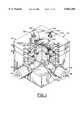
- FIG. 1is an isometric view of a micro mass flow controller of the present invention with a portion of the valve body cut away to reveal internal valve and other controller components;
- FIG. 2is a front elevation view of the micro mass flow controller embodiment of FIG. 1;
- FIG. 3is a top elevation view of the micro mass flow controller embodiment of FIG. 1;
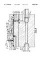
- FIG. 4is an enlarged cross-sectional view of the micro mass flow controller taken along line 4--4 of FIG. 3;
- FIG. 5is a graphical representation of an exemplary time-modulated voltage signal and duty cycle of the valve coordinated with a corresponding graphical representation of the oscillating digital valve positions;
- FIG. 6is an enlarged diagrammatic elevation view of the laminated bender valve actuator components connected in series to a driver circuit illustrating how valve opening bending moments are produced;
- FIG. 7is an enlarged diagrammatic view of the valve activator components similar to FIG. 6, but illustrating how valve closing bending moments are produced;
- FIG. 8is an enlarged diagrammatic elevation view of the laminated bender valve actuator components connected in parallel to a drive circuit illustrating how valve opening bending moments are produced;
- FIG. 9is an enlarged diagrammatic view of the valve actuator components similar to FIG. 8, but illustrating how valve closing bending moments are produced;
- FIG. 10is an enlarged cross-sectional view of the valve closure and valve seat of the micro mass flow controller of FIG. 1;
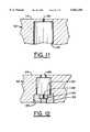
- FIG. 11is an enlarged cross-sectional view of an alternate sonic orifice structure
- FIG. 12is an enlarged cross-sectional view of still another sonic orifice structure
- FIG. 13is a cross-sectional view of the pressure transducer of FIG. 4, but enlarged to illustrate flexure of the diaphragm and positioning of the strain gauges;
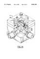
- FIG. 14is an isomeric view of a modified version of the micro mass flow controller shown in FIG. 1;
- FIG. 15is a functional block diagram of a control circuit for the controller of FIG. 1;
- FIG. 16is a diagrammatic cross-sectional view of an alternate embodiment controller with a dump valve feature for controlling outlet pressure
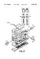
- FIG. 17is an exploded isometric view of components of an implementation of the alternate embodiment controller of FIG. 16;
- FIG. 18is another exploded isometric view of the implementation of FIG. 17, but viewed from a different perspective;
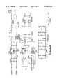
- FIG. 19is a functional block diagram of a control circuit for the alternate embodiment controller of FIGS. 16-18;
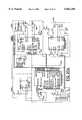
- FIG. 20ais a schematic circuit diagram of the CPU circuit and read-out circuit of the controllers of this invention.
- FIG. 20bis a schematic circuit diagram of the pressure transducer and user inputs for the controllers of this invention.
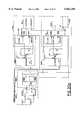
- FIG. 20cis a schematic circuit diagram of the valve actuator driver circuits of the controllers of this invention.
- FIG. 20dis a schematic circuit diagram of voltage supply circuits for the controllers of the present invention.
- FIG. 1A micro mass flow controller 10 suitable for controlling and metering very small flows of gas at very low pressures is shown in FIG. 1 with a portion of the flow controller body cut away to reveal valve and other controller components, as will be described in more detail below.
- gas from a supply sourceflows into the controller 10 through an inlet connector 12, as indicated by arrow 14, and through internal inlet ducts 16, 18, as indicated by arrows 20, 22, into an inlet plenum 24. From the inlet plenum 24, the gas flows through a control valve 26 into an orifice 28, where it is choked at sonic velocity before flowing through an internal outlet duct 30, as indicated by arrow 32, and out an outlet fitting 34, as indicated by arrow 36.
- the mass flow rate M of the gasis directly proportional to a ratio of the pressure P 1 in the inlet plenum 24 to the square root of the temperature T 1 of the gas.
- the mass flow rate Mcan be determined by the equation: ##EQU1## where:
- P 1pressure in inlet plenum 24
- C*a correction factor that depends on the type of gas
- Across-sectional area of the orifice 28.
- T 1absolute temperature (degrees Kelvin) of the gas in the inlet plenum 24.
- a significant feature of this inventionis the time modulated valve 26 in combination with the sonic choked orifice 28 for controlling mass flow rate at something less than full-time sonic choked flow.
- alternate closing and opening of the valve 28is time modulated to create a valve duty cycle that is something less than full-time open (maximum flow set point) and something more than full-time closed (minimum flow set point). Therefore, the time modulated valve 26 can control the effective flow rate M* at any desired rate between the maximum set point M max and the minimum set point M min for any inlet plenum pressure P 1 and temperature T 1 by setting the time modulation or duty cycle of the valve 26, as will be described in more detail below.
- valve 26comprises an elongated, laminated bender valve actuator 40 that bends upwardly as indicated by phantom line 40' when voltage of one polarity (e.g., positive) is applied and that bends downwardly, as indicated by phantom line 40" when voltage of the opposite polarity (e.g., negative) is applied. Therefore, when the voltage is alternated between positive and negative, the distal end 42 of the elongated actuator 40 oscillates up and down, as indicated by the double-headed arrow 44.
- one polaritye.g., positive
- phantom line 40voltage of the opposite polarity
- a closure member 46 under the actuator 40 adjacent the distal end 42occludes the valve bore 84 and orifice 28 to prevent gas flow through orifice 28, thus closing the valve 26.
- the closure member 46moves away from the valve bore 84, thus opening the valve 26 and allowing gas to flow through orifice 28.
- the open position 40'is open sufficiently such that the gas flow entering valve bore 84 is not impeded or choked between the closure member 46 and the surface 114 and so that the effective pressure at orifice 28 is substantially the stagnant plenum pressure P 1 .
- the actuator 40can and is preferably operated in a digital manner, snapping alternately from closed position 40" to open position 40' and from open position 40' to closed position 40".
- the valve actuator 40can be driven to bend upwardly to the open position 40' by applying a positive voltage, and it can be driven to the closed position 40" by applying a negative voltage, as indicated schematically by the oscillating actuator driver circuit 50 in FIG. 4, as will be described in more detail below. Therefore, the dwell time of the valve actuator 40 in either the open position 40' or the closed position 40" can be controlled by modulating how long the voltage on the valve actuator is held positively and how long it is held negatively, respectively, in each open/close oscillation cycle. For example, if, as illustrated in FIG.
- the voltageis time-modulated to be held positive for twenty-five percent of the time t of a cycle (i.e., 0.75 t) and negative for the remaining seventy-five percent of the time t of a cycle (i.e., 0.75 t), the valve actuator 40 will be in the open position 40' for twenty-five percent of the time and in the closed position 40" for seventy-five percent of the time. Therefore, the valve 26, in this example, has a duty cycle of 0.25, where duty cycle is defined as the ratio of open time to total time.
- the mass flow rate M through the orifice 28 for a particular gas at a particular measured inlet plenum pressure P 1 and temperature T 1is calculated according to equation (1) to be ten standard cubic centimeters per minute (10 sccm) and the valve 26 is time modulated to have a duty cycle of 0.25, then the actual or effective mass flow rate M according to formula (2) above is:
- inlet plenum pressure P 1 and temperature T 1varying the duty cycle of the valve between zero and one would result in a linear variation of the effective mass flow rate M* between, in this example, 0 and 10 sccm.
- duty cyclecan be varied enough to compensate for such variation in the mass flow rate M to maintain a desired effective mass flow rate M*.
- the time modulated controller 10can provide very responsive and very accurate mass flow control of gases flowing at these very low flow rates.
- the piezoelectric crystal actuator 40comprises two elongated piezoelectric bender devices 52, 54 laminated together with an electrically conductive material 56, such as aluminum or other metal, sandwiched between the two piezoelectric benders 52, 54. Piezoelectric benders have the characteristic of expanding or contracting when voltages are applied. In the actuator 40 illustrated in FIGS.
- the piezoelectric bender 52has the characteristic of contracting in response to application of a positive voltage as indicated by contraction arrows 58, while the piezoelectric bender 54 has the characteristic of expanding in response to application of a positive voltage as illustrated by expansion arrow 60.
- the result of such positive voltage, as illustrated in FIG. 6,is that the actuator 40 will tend to curl upwardly to the open valve position 40'.
- the voltage polarityis reversed to apply a negative voltage, as indicated in FIG. 7, the opposite action occurs in that the piezoelectric bender 52 expands as illustrated by expansion arrow 62, while the piezoelectric bender 54 contracts as illustrated by the contraction arrow 64.
- the result of such negative voltage, as illustrated in FIG. 7,is that the actuator 40 will tend to curl downwardly to the closed valve position 40".
- the metal conductor material 56is provided to distribute the applied voltages over the lengths of the piezoelectric benders 52, 54, which are usually semiconductor materials.
- the electrical connection illustrated schematically in FIGS. 4, 6, and 7connects the piezoelectric benders 52, 54 in series to the driver circuit 50.
- the piezoelectric bimorphs 52, 54can be connected in parallel to the driver circuit 50, as illustrated in FIGS. 8 and 9 to achieve the same overall effect with less voltage, but more current required from the driver circuit 50.
- Elongated piezoelectric bimorphs suitable for this valve actuator applicationcan be obtained from Morgan Matrax, of Cincinnati, Ohio.
- the actuator 40be driven to the closed position 40" with a voltage that initially goes instantaneously from positive to negative.
- the speed of the distal end 42 of the actuator 40be slowed to reduce momentum upon contact or impact in order to reduce shock, wear, and tear on the actuator 40 and the valve closure member 46.
- Such slowing of the actuator 40 for a soft landing of the valve closure member 46 on the valve seat 70can be accomplished by rounding the driver voltage signal as indicated at 72 in FIG. 5.
- the driver signal voltagemakes the transition from positive to negative virtually instantaneously, as indicated by the vertical position 74 of the driver signal cycle to achieve almost instantaneous transition from the valve open position 40' to the valve close position 40".
- the rate of change of the voltagedecreases in the curved portion 72 of the driver signal cycle to allow the inherent bias against bending in the laminated bimorph actuator 40 structure to decelerate movement toward the closed position 40" as indicated by a comparable curve 76 in the valve position graph of FIG. 5 in order to effect the desired soft landing of the valve closure member 46 on the valve seat 70 shown in FIG. 10.
- a similar deceleration of the actuator 40 near the open position 40', as indicated by the curve 78 in FIG. 5,may also be desired to dampen shocks and vibrations in the actuator 40, even though there is no physical contact of the actuator 40 with any other component at the open position 40'.
- the valve closure member 46For unrestricted gas flow at sonic velocity in the orifice 28 at the low pressures and mass flow rates for which the flow controller 10 of this invention was created, the valve closure member 46 only has to move off the valve seat by about 0.006 inch, which can be accomplished almost instantaneously by the vertical portion 80 of the voltage transition signal in FIG. 5 and still leave some further movement for deceleration 78.
- Such deceleration 78can be provided by slowing rate of voltage increase as shown by the curve 82 in the driver signal of FIG. 5.
- Another option for maintaining an even tighter seal at closureis to increase the magnitude of the negative voltage after the soft landing has been achieved to provide a stronger sealing force. For example, after the soft closing deceleration voltage curve 72, the magnitude of the negative voltage can be ramped even higher to the level 83 and held there for the remainder of the cycle time.
- Sonic choked flow of the gas through the orifice 28is required for equation (1) to be an accurate determination of mass flow rate M, as described above.
- an orificesuch as orifice 28 shown in FIG. 1, 4, and 10.
- two conditionsmust be maintained.
- the ratio of stagnant pressure P 1 above the orifice 28 to stagnant pressure P 2 below the orifice 28must be in the range of at least about 1.4 to 1.5 (P 1 /P 2 ⁇ 1.4 to 1.5) and is preferably kept at least 2.0 (P 1 /P 2 ⁇ 2.0) to assure sonic choked flow conditions are maintained.
- the mean free path ⁇ of the gas moleculesmust be smaller than the diameter of the orifice 28.
- the mean free path ⁇is about 0.002 inch. Therefore, a relatively large orifice 28 of at least 0.002 inch and preferably about 0.005 inch is very feasible for pressures in the range of about 3 p.s.i.a. down to 3 torr or less. Operation at higher inlet plenum pressure P 1 is feasible, of course, and, according to equation (1) would accommodate greater maximum mass flow rates M. However, such higher pressures and flow rates diminish the ability to achieve fine and very accurate control of very low mass flow rates.
- Such low plenum operating pressures P 1 of, for example, 3 p.s.i.a. or lessalso has the advantage of minimizing leakage rate through the valve 26, when the valve closure member 46 is seated on the valve seat 70, as shown in FIG. 10.
- another feature of this inventionis the structure and method of fabricating the valve closure member 46. Specifically, as best seen in FIG. 10 along with continuing reference also to FIGS. 1 and 4, the valve seat 70 is provided by the rim around the opening of bore 84 into inlet plenum 24.
- the valve closure member 46is preferably a patch of shimstock or other metal foil adhered to the actuator 40 by a suitable adhesive 86, such as epoxy.
- the actuator 40 and closure member 46are preferably forced tightly onto the valve seat 70, for example by pulling a vacuum through internal outlet duct 30 or by any other suitable force applying mechanism or procedure applying mechanism or procedure or by applying a closing voltage to the bender.
- Such forcing of the valve closure member 46 onto the valve seat 70 with enough force to create a crease 85 in the closure member 46 and holding the force until the adhesive 86 dries or cureshas the advantage of forming and keeping the crease 85 as an exact fit to the unique shape and size of the valve seat 70 for a very effective seal when the actuator 40 is in the closed position 40".
- Other closure memberscan also be used.
- the curved contourcan include a hemisphere and may be a spherical ball. Such spherical ball may be metallic and attached magnetically to a solenoid.
- the controller 10can be constructed with any suitable housing, although one suitable embodiment is illustrated in FIGS. 1-4.
- the main inlet and outlet conduits 86, 88, respectively,are provided in a main body section 90, which also provides the structure for threaded connection of the inlet fitting 12 and outlet fitting 34.
- An intermediate body section 92provides a substrate for the orifice 28 and for mounting the valve actuator 40.
- O-ring seal 94seals the conjunction between inner inlet ducts 16, 18 in the main body section 90 and intermediate section 92, respectively.
- O-ring seals 94, 96seal the conjunction between outlet ducts 16 and 98 in main body section 90 and intermediate body section 92, respectively.
- the top body section 100 together with the intermediate section 92forms the inlet plenum 24, and it covers and protects the valve actuator 40.
- An O-ring seal 102 around the periphery of the inlet plenum 24seals the inlet plenum 24 from the outside.
- Machine bolts 108tighten and hold the main body section 90, intermediate body section 92, and top body section 100 together.
- the valve actuator 40is cantilever mounted at its proximal end 110 on a shim 112 adhered to the top surface 114 of the intermediate body section 92. Electrical connection of the actuator 40 to common is provided by spring contact 116 mounted in a hole 118 bored into the top surface 114 of the intermediate body section 92 and to the driver circuit 50 by a spring contact 120 through an electrode assembly 122 that extends through the top body section 100.
- the orifice 28can be constructed in a number of ways.
- the preferred structureis shown in FIGS. 1, 4, and 10, including a jewel insert 124, such as sapphire, with the orifice 28 extending through the jewel insert 124.
- the jewel insert 124is press fit or adhered into a bore 126 in a manner that leaves a portion 84 of the bore 126 extending between the jewel insert 124 and the top surface 114 of the intermediate body section 92.
- the portion 84 of the bore 126 that extends between the jewel insert 124 and the top surface 114is preferably larger in diameter, thus larger in circumference and area than the orifice 28 for several reasons.
- the larger area of the portion 84 of bore 126lessens the distance that the valve closure member 46 has to be lifted above the valve seat 70 to avoid sonic flow between the closure member and the top surface 114, thereby ensuring that the sonic choked flow occurs in the orifice 28 and not between the top surface 114 and closure member 46.
- the larger circumference of the valve seat 70enhances the seal of the valve closure member 46 on the valve seat 70.
- the jewel insert 124is used preferably for very small diameter orifices 28, which are difficult to drill with sufficient precision in metal. However, simply drilling or precision boring the orifice 28 directly into the metal of the intermediate body section 92, while difficult, is certainly feasible. For example, as shown in FIG. 11, the outlet duct 30 can extend closer to surface 114, and the orifice 28 can be simply drilled from surface 114 to the outlet duct 30.
- FIG. 12Another orifice embodiment that has been used with this invention is shown in FIG. 12.
- the intermediate body section 92also has the hole 84 with a larger diameter than the orifice 28 bored from the top surface 114 into the outlet duct 30.
- the jewel insert 124 with the orifice 28is press fit into a brass insert 128, which in turn is either press fit or adhered in the widened portion 130 at the bottom of outlet duct 30.
- This embodimenthas the disadvantage of excess volume of outlet duct 30 between top surface 114 and orifice 28, which causes some capacitance and resulting lag in responsiveness between the time modulated valve 26 (not shown in FIG. 12) and the orifice 28.
- the pressure measurements P 1 and P 2can be made with conventional pressure gauges.
- a conventional pressure gauge 104 for measuring the outlet pressure P 2is illustrated diagrammatically in FIGS. 2-4 connected to the outlet conduit 88 via an internal pressure connector duct 106 in the main body section 90.
- conventional pressure gauges or transducers that are adapted for connection to ports or fittingshave the disadvantage of holding gases in their interior volumes, which causes residual contamination and other problems. Therefore, this invention includes an integral pressure transducer 130 in the top body section 100 for measuring the stagnant gas pressure P 1 in the inlet plenum 24.
- This pressure transducer 130comprises a diaphragm 132 formed by a thin sheet of metal left after machining a cavity 134 into a portion of the roof 136 of the top body section 100 that covers the inlet plenum 24.
- the diaphragm 132is preferably, but not necessarily, circular in shape. As best seen in FIG. 4, the diaphragm 132 is integral with the inside roof surface 138 that forms the top of the inlet plenum 24, so it does not have an internal volume that could catch and hold residual gas that would prolong cleaning time or instrument response time if gas composition changes or the system is purged for some reason.
- the diaphragm 132is thin enough to flex, as illustrated by phantom lines 132' as pressure P 1 in inlet plenum 24 varies from atmospheric pressure above the diaphragm 132.
- Strain gauges 140, 142, 144, and 146are adhered to the outer surface of the diaphragm 132 to measure the extent to which the diaphragm 132 flexes, which, when calibrated empirically, indicates the gauge pressure in the inlet plenum 24.
- another external pressure gauge(not shown in FIG. 4) is needed to measure atmospheric pressure, which can be added algebraically to the gauge pressure detected by pressure transducer 130 to get the absolute pressure P 1 , as is understood by persons skilled in the art.
- the diaphragm 132has maximum strain, i.e., stretch, at the center 148, where curvature of the flexed diaphragm 132' is concave, and adjacent the outside edge 150, where curvature of the flexed diaphragm 132' is convex, as illustrated diagrammatically in FIG. 13.
- strain gauges 140, 142are preferably placed at or near the zones of maximum deflection 148, 150, respectively, in order to get the best strain signals from those strain gauges 140, 142, as the diaphragm 132 flexes due to differential between the pressure P 1 under the diaphragm 132 and the atmospheric pressure P atmospheric over the diaphragm 132.
- voltage measurements from strain gaugesin addition to being indicative of strain, are affected by temperature changes. Therefore, unless there is a correction for temperature changes, the voltage measurements from the strain gauges 140, 142 may not indicate magnitude of strain, thus pressure differential between P 1 and P atmospheric , accurately.
- strain gauges 144, 146are placed at the neutral zone 152 of the diaphragm 132, where there is no strain (i.e., stretch) in the diaphragm 132 even as it flexes as indicated at 132'.
- strain gauge 144is seen in FIGS. 4 and 13 because of the location of the cross-section of those views, but both strain gauges 144, 146 can be seen in FIGS. 1 and 3.
- any change in voltage measurements from the strain gauges 144, 146 at the neutral zone 152are due to temperature change alone rather than to any pressure change. Consequently, such measurements from the strain gauges 144, 146 at the neutral zone 152 can be used to correct measurements from strain gauges 140, 142 for temperature changes in order to get measurements that indicate accurate strains in the diaphragm 132 due to pressure.
- Equation (1)also requires temperature of the gas for accurate determination of mass flow rate M through the sonic choked orifice 28. If the gas is stored at room temperature, room temperature can be assumed for purposes of the mass flow rate M calculation. However, for more accurate calculations of mass flow rate M, a thermocouple assembly 154 or any other common temperature measuring transducer can be mounted on the top body section 100 to extend into the inlet plenum 24, as illustrated in FIGS. 1-4.
- the controller 10in addition to having the ability to control effective mass flow rate M* very accurately and reliably for very small gas flow rates and at very low pressures, as described above, can also be used to meter, i.e., measure mass quantities M of gas that flows through the controller 10 over any time period. If the effective mass flow rate M* is constant throughout the time period of interest, the mass M of the gas is simply the effective mass flow rate M* multiplied by the time period of interest. If the effective mass flow rate M* varies during the time period of interest, the mass M can, of course, be determined by summation of masses in numerous small time increments during the time period of interest or by integration over the time period of interest, as is understood by persons skilled in the art.
- FIG. 14A slightly modified version 10' of the micro mass flow controller is shown in FIG. 14 to illustrate several variations that may be desirable under some circumstances.
- this modified version 10'is shown with a sonic nozzle 156, which, as is understood by persons skilled in the art, has an inlet section 158 that converges to a throat 160 of minimum cross-sectional area and then a diverging outlet section 162.
- An advantage of a nozzle over an orificeis that energy is recovered in the diverging outlet section 162 so that the ratio of inlet pressure P 1 to outlet pressure P 2 needed to maintain sonic choked flow through the throat 160 can be smaller than needed to maintain sonic choked flow in an orifice.
- a ratio of P 1 /P 2 ⁇ 1.15 to 1.20is usually sufficient to maintain sonic choked flow in a nozzle. Therefore, it may be desirable to use the nozzle 156 rather than the orifice 28 in situations where outlet pressure P 2 has to be maintained closer to available inlet pressure P 1 or in applications where conservation of energy is needed.
- the cavity 134' for the pressure transducer 130is machined into the inside or bottom surface 138 of the top body section 100 so that the diaphragm 132 is integral with the top surface 136 rather than the bottom surface 138.
- the periphery of the diaphragm 132is generally indicated by phantom lines 132' in FIG. 14.
- An advantage of this variationis that the strain gauges 140, 142, 144, 146 are easier to place on the top surface 136 than inside the cavity.
- inlet plenum pressure P 1 measurementsare effective stagnant pressure measurements as required for accurate mass flow rate M determinations with equation (1).
- the modified controller 10' in FIG. 14has substantially the same components and operates in substantially the same manner as the controller 10 shown in FIGS. 1-13 and described above. Therefore, no additional description of the modified controller 10' is needed.
- FIG. 15A functional block diagram of an appropriate electronic circuit for implementing the micro mass flow controller 10 according to the present invention is shown in FIG. 15.
- a desired effective mass flow rate M* set pointcan be provided by an analog signal, such as a voltage between 0-10 volts or a current between 4-20 MA, as shown at block 170.
- This set point signalis amplified and converted from analog to digital format at block 172 and delivered to a microprocessor or central processing unit (CPU) 174.
- Analog voltage signals from the strain gauges 140, 142, 144, 146are amplified and converted from analog to digital format at block 176 and delivered to the CPU 174.
- the strain gauge measurementsprovide gauge pressure, not absolute pressure P 1 so atmospheric pressure signals from a conventional atmospheric pressure transducer 178 are amplified and converted from analog to digital format at block 180 for delivery to the CPU for use in converting the strain gauge measurements to absolute inlet plenum pressure P 1 .
- gas temperature T 1 input from a thermocouple 154is used, as described above, the T 1 signals are amplified and converted from analog to digital format at block 182 for delivery to the CPU 174. Otherwise, an assumed room temperature or any other desired temperature correction can be programmed into the CPU 174.
- the CPU 174reads all the incoming signals described above, provides the appropriate calculations and interpretations to set the duty cycle required for the desired effective mass flow rate M*, outputs the duty cycle signals to a digital to analog waveform producer 184, and outputs actual effective mass flow rate M* signals in digital format.
- the duty cycle signals produced by the CPU 174can be essentially digital on/off signals of the needed time modulation for the open and close position of the controller valve 26, as described above.
- a convenient, but certainly not the only, way to provide a soft landing waveform as described aboveis to convert the on/off duty cycle signal from the CPU 174 to analog form with an RC circuit, as indicated at block 184.
- the actuator driver circuit 50includes a high power supply and amplifier to boost the waveform signal from block 184 to a level needed to power the actuator 40 of the controller valve 26 for the required oscillatory movement 44 as described above.
- the actual mass flow rate M* signal that is produced by the CPU 174can be used for any desired digital or analog display, equipment control, recording, analysis, or other function desired. In FIG. 15, it is shown going through an amplifier and digital to analog conversion at block 186 for an analog output signal representing the actual mass flow rate M* at block 188.
- the metering function of the controller 10can be implemented by summing or integrating the actual mass flow rate M* over any desired time period. Such a metering function could be provided by the CPU 174 or by an external circuit using the M* out put of block 188, as will be understood by persons skilled in the art.
- the CPUcan also be programmed to provide the other functions and calculations described above, as will be understood by persons skilled in the art. For example, it can utilize the measurement signals from the neutral position strain gauges 144, 146 to correct the measurements from strain gauges 140, 142 for variations or drift due to temperature. It can also use empirically determined and programmed relationships to convert measured strains of the diaphragm to gauge pressure valves and then use the measured atmospheric pressure P atmospheric with the gauge pressures to determine inlet plenum pressure P 1 in absolute pressure terms.
- the CPU 174can also be programmed to convert temperature signals from block 154 to gas temperature T 1 in absolute degrees Kelvin as needed for use in equation (1). Of course, the CPU 174, as mentioned above, is also programmed to utilize these and other inputs to make the calculations of mass flow rate M, determine duty cycle, and the like, in as many repetitions and over whatever times are desired.
- a dump valve 190can be provided in an outlet plenum 192 downstream of the sonic orifice 28 or sonic nozzle (not shown in FIG. 16) to help provide a precise outlet pressure P 2 , as required, for example, in backside wafer cooling applications in the semiconductor fabrication processes. If it is important to known the amount of gas dumped from the outlet plenum 192 by the dump valve 190, the dump valve 190 can be made as a time-modulated, sonic choked valve in much the same manner and with similar components as the time-modulated, sonic choked valve 26 described above.
- outlet plenum 192is provided downstream of the sonic orifice 28, and the normal flow of gas from the sonic orifice 28 is into the outlet plenum 192 and out the outlet fitting 34, as indicated by flow arrow 36, to wherever the controlled flow of gas is used at the desired outlet pressure P 2 , such as in a backside wafer cooling system (not shown).
- the duty cycle of the main controller valve 26can ordinarily be controlled to maintain the outlet pressure P 2 at any desired level as well as to measure effective mass flow rate M* of the gas being dispensed while leaving the dump valve 190 closed, so long as the P 1 /P 2 pressure ratio required for sonic choked flow in orifice 28 is maintained and so long as the gas flow required to maintain outlet pressure P 2 at the desired level does exceed the maximum mass flow rate M of the orifice 28 if the valve 26 was always in open position.
- the gas flow rate needed to maintain the desired outlet pressure P 2is less than the rate at which gas can leak through the valve 26 when the valve 26 is held in closed position, the outlet pressure P 2 would build toward P 1 in the inlet plenum 24.
- the dump valve 190can be actuated to open and dump some of the gas from outlet plenum 192, as indicated by flow arrows 194, 196, 198 to a vacuum pump or chamber (not shown). If the ratio of outlet pressure P 2 to vacuum pressure P 3 is enough to maintain sonic choked flow through the orifice 202 in valve 190, i.e., P 2 /P 3 ⁇ 1.5 to 2.0, then mass flow rate through orifice 202 can be measured by equation (1), as described above for orifice 28.
- dump valve 190Since the amount of gas that leaks through valve 26, thus has to be dumped by dump valve 190 from outlet plenum 192 to maintain outlet pressure P 2 at the desired level, is likely to be small, it may not be desirable to simply open dump valve 190 until the outlet pressure P 2 drops. Such action could cause overshoot by dumping too much gas and causing P 2 to drop below the desired level. Therefore, it may be preferable to operate the dump valve 190 in a time-modulated manner similar to main control valve 26, both for more gradual, controlled dump, and for more accurate measurement of effective mass flow rate of the gas being dumped.
- the effective mass flow rate of the gas being dumped by dump valve 190can be subtracted from the effective flow rate M* of the sonic orifice 28, if they are operating simultaneously, to provide actual mass flow rate of gas being delivered through the outlet fitting 34.
- metering of gas dumped and gas delivered through outlet fitting 34can also be provided by summation or integration over time, as described above.
- the bimorph actuator 206 of dump valve 190is essentially the same as actuator 40 of the main controller valve 26.
- the dump fitting 208provides a connection of the dump valve 190 to the vacuum pump or chamber.
- FIGS. 17 and 18An actual structure for implementation of the dump embodiment 200 of FIG. 16 is shown in FIGS. 17 and 18. Essentially, the gas flow route arrows in FIG. 17 show how gas flows through the components. From the inlet fitting, the gas flows through inlet duct 18 into inlet plenum 24 where valve 26 and sonic orifice 28 are located. From orifice 28, the gas flows into the outlet plenum 192, from where flow can go either to the P 2 pressure chamber 212, where P 2 outlet pressure is measured by outlet pressure transducer 204 and on through the outlet fitting 34 or to the dump valve chamber 210, where dump valve 190 and sonic orifice 202 are located. Gas that is dumped through orifice 202 flows to dump gas conduit 216, which leads to dump fitting 208.
- a pump-down valve 220 positioned in a pump-down valve chamber 222can be opened to use whatever vacuum pump (not shown) that is connected to dump fitting 208 in order to pull gas backward through outlet fitting 34 from whatever system is connected to outlet fitting 34.
- An appropriate control circuit for the dump controller 200 shown in the function block diaphragm of FIG. 19is similar to the control circuit for the mass flow controller 10 shown in FIG. 15 for the common components.
- an input of the desired outlet pressure P 2as shown at block 224, to the CPU 174 is needed along with input signals from the outlet pressure transducer 204 amplified and analog to digital converted at block 205.
- a second set of digital to analog waveform generator 226, and actuator driver 228is needed for taking duty cycle output from CPU 174 to create drive appropriate time-modulated drive signals for the actuator 206 of dump valve 190.
- the CPU 174can also calculate and output actual output pressure P 2 at block 230 after appropriate amplification and digital to analog conversion, if desired, at block 232.
- the CPU 174can be programmed to output signals indicative of actual dump mass flow rate through dump orifice 202 of dump valve 190 by using outlet pressure P 2 in equation (1) similar to the description above for actual mass flow rate M* for the main controller valve 26, as indicated at block 234, and, if desired, in analog format after the amplification and digital to analog conversion indicated at block 236.
- Other optional functions of the CPU 174may include outputting control signals to shut-off valve 218 and pump-down valve 220, which would be well within the capabilities of persons skilled in the art and do not need further explanation here.
- FIGS. 20a-20dAn exemplary electronic circuit schematic for operating the controller 10 as well as the dump controller embodiment 200 is shown in FIGS. 20a-20d.
- the CPU circuit 174 in FIG. 20aperforms all of the functions described above, and the time divider circuit 238 divides the clock by two, which is needed for the A/D converters.
- the output circuit 240includes a D/A converter 242, which performs the digital to analog conversions 186, 236, 232 of FIG. 19 for the outlet pressure P 2 and the flow rates.
- the analog outlet pressure P 2is at 230, which can be, for example in 0-10 volts where 10 torr equals 10 volts.
- the actual mass flow rate M* output 188is also analog and can be, for example 0-10 volts where 10 sccm equals 10 volts.
- a communications port circuit 244is provided for diagnostics.
- the strain gauge circuits 246, 248provide the pressure transducer signal acquisition functions of blocks 140, 142 and 204, respectively, of FIG. 19, and the data input circuit 250 provides the input connection for acquiring desired effective mass flow rate M* set point 170 and/or desired outlet pressure P 2 set point 224. These inputs are in analog format, such as 0-10 volts equals to 0-10 torr and/or 0-10 volts equals 0-10 sccm.
- the A/D converter circuit 252provides the analog to digital conversions of the pressure transducer input signals from circuit 246, 248 and of the desired flow rate and/or pressure inputs from input circuit 250, which are also the functions 176, 205, and 172 of FIG. 19.
- a high voltage power supply 254which is part of the functions of the actuator drivers 50, 228 in FIG. 19, is used with the RC circuit to shape the actuator driver waveforms as discussed in relation to FIG. 5 and to functions 184, 226 in FIG. 19.
- Optional isolator circuits 258, 260isolates the CPU 174 from the high voltage of the actuator driver circuits 50, 228, which contain switching transistors 262, 264 and 266, 268 for feeding the time-modulated high voltage driver signals to the valve actuators 40, 206, respectively.
- the valve actuators 40, 206are also sometimes called benders.
- FIG. 20dshows the 5 volt power supply, 12 volt power supply and various filters and capacitors, which are well-within the capabilities of persons skilled in the art and need no further detailed description for an understanding of this invention.
- controllers 10 and 200to operate at subatmospheric pressures, for example, in the 0.25 to 3 p.s.i.a. range, minimizes leakage problems through the valves 26, 192 as well as allows the use of larger orifices that are less likely to clog, as discussed above.
- multiple time-modulated, sonic choked flow valves 26can be used together in parallel, and, if desired, all from the same inlet plenum 24, thus requiring only one pressure transducer 130 for a common inlet plenum pressure P 1 for use in equation (1) for all of the multiple sonic choked orifices used.
- each of the multiple valvescould have different sized orifices and/or operate at different controlled duty cycles for precise flow rate control.
- the actuator 40can close the valve 26 within about one microsecond, so cycle time of about one millisecond (1 msec), i.e., a frequency of about one kilohertz (1 KHz) is an appropriate operating range for the actuator 40, although operation at a resonant frequency should obviously be avoided. It may also be appropriate to encapsulate the actuator 40 with a protective coating, such as, for example, silicon nitride or other material, to prevent contamination of the gas flowing through the controller 10. A turndown ratio of 400:1 is easily achievable, and over 1000:1 is likely. Response time of 30 milliseconds is within the capabilities of the controller 10, and even less response time may be achievable by limiting capacitance volumes in the valve 26. Repeatability and linearity of control measurements within 0.25% is also within the capabilities of the controller 10.
Landscapes
- Engineering & Computer Science (AREA)
- General Engineering & Computer Science (AREA)
- Mechanical Engineering (AREA)
- Physics & Mathematics (AREA)
- General Physics & Mathematics (AREA)
- Automation & Control Theory (AREA)
- Chemical & Material Sciences (AREA)
- Dispersion Chemistry (AREA)
- Flow Control (AREA)
- Electrically Driven Valve-Operating Means (AREA)
- Respiratory Apparatuses And Protective Means (AREA)
Abstract
Description
M*=M×Duty Cycle. (2)
M*=10 sccm×0.25=2.5 sccm.
Claims (34)
Duty Cycle=M*/M.
Priority Applications (9)
| Application Number | Priority Date | Filing Date | Title |
|---|---|---|---|
| US08/799,304US6062256A (en) | 1997-02-11 | 1997-02-11 | Micro mass flow control apparatus and method |
| CNB988024551ACN1158585C (en) | 1997-02-11 | 1998-02-11 | Micromass flow control device and method |
| EA199900738AEA001508B1 (en) | 1997-02-11 | 1998-02-11 | Fluid flow controller apparatus, actuator and method producing thereof |
| PCT/US1998/002805WO1998037343A2 (en) | 1997-02-11 | 1998-02-11 | Micro mass flow control apparatus and method |
| EP98906404AEP0960364A4 (en) | 1997-02-11 | 1998-02-11 | APPARATUS AND METHOD FOR REGULATING VERY LOW MASS FLOW RATE |
| KR1019997007217AKR20000070952A (en) | 1997-02-11 | 1998-02-11 | Micro mass control apparatus and method |
| US09/021,792US6095175A (en) | 1997-02-11 | 1998-02-11 | Clad piezoelectric valve actuator and application of same in controlling highly reactive and corrosive gases |
| JP53673598AJP2001513922A (en) | 1997-02-11 | 1998-02-11 | Micromass flow control device and method |
| US09/607,301US6230731B1 (en) | 1997-02-11 | 2000-06-30 | Valve closure seating method and apparatus |
Applications Claiming Priority (1)
| Application Number | Priority Date | Filing Date | Title |
|---|---|---|---|
| US08/799,304US6062256A (en) | 1997-02-11 | 1997-02-11 | Micro mass flow control apparatus and method |
Related Child Applications (1)
| Application Number | Title | Priority Date | Filing Date |
|---|---|---|---|
| US09/021,792Continuation-In-PartUS6095175A (en) | 1997-02-11 | 1998-02-11 | Clad piezoelectric valve actuator and application of same in controlling highly reactive and corrosive gases |
Publications (1)
| Publication Number | Publication Date |
|---|---|
| US6062256Atrue US6062256A (en) | 2000-05-16 |
Family
ID=25175550
Family Applications (3)
| Application Number | Title | Priority Date | Filing Date |
|---|---|---|---|
| US08/799,304Expired - Fee RelatedUS6062256A (en) | 1997-02-11 | 1997-02-11 | Micro mass flow control apparatus and method |
| US09/021,792Expired - Fee RelatedUS6095175A (en) | 1997-02-11 | 1998-02-11 | Clad piezoelectric valve actuator and application of same in controlling highly reactive and corrosive gases |
| US09/607,301Expired - LifetimeUS6230731B1 (en) | 1997-02-11 | 2000-06-30 | Valve closure seating method and apparatus |
Family Applications After (2)
| Application Number | Title | Priority Date | Filing Date |
|---|---|---|---|
| US09/021,792Expired - Fee RelatedUS6095175A (en) | 1997-02-11 | 1998-02-11 | Clad piezoelectric valve actuator and application of same in controlling highly reactive and corrosive gases |
| US09/607,301Expired - LifetimeUS6230731B1 (en) | 1997-02-11 | 2000-06-30 | Valve closure seating method and apparatus |
Country Status (7)
| Country | Link |
|---|---|
| US (3) | US6062256A (en) |
| EP (1) | EP0960364A4 (en) |
| JP (1) | JP2001513922A (en) |
| KR (1) | KR20000070952A (en) |
| CN (1) | CN1158585C (en) |
| EA (1) | EA001508B1 (en) |
| WO (1) | WO1998037343A2 (en) |
Cited By (76)
| Publication number | Priority date | Publication date | Assignee | Title |
|---|---|---|---|---|
| US6247493B1 (en)* | 2000-03-09 | 2001-06-19 | Richard C. Henderson | Miniature pulsatile flow controller |
| US6360762B2 (en)* | 1999-04-22 | 2002-03-26 | Fujikin Incorporated | Method for feeding gases for use in semiconductor manufacturing |
| US20030230239A1 (en)* | 2002-06-17 | 2003-12-18 | Applied Materials, Inc. | Gas flow division in a wafer processing system having multiple chambers |
| US20040035358A1 (en)* | 2002-08-23 | 2004-02-26 | Cem Basceri | Reactors having gas distributors and methods for depositing materials onto micro-device workpieces |
| US6701223B1 (en)* | 2000-09-11 | 2004-03-02 | Advantica, Inc. | Method and apparatus for determining optimal control settings of a pipeline |
| US20040040502A1 (en)* | 2002-08-29 | 2004-03-04 | Micron Technology, Inc. | Micromachines for delivering precursors and gases for film deposition |
| US20040040503A1 (en)* | 2002-08-29 | 2004-03-04 | Micron Technology, Inc. | Micromachines for delivering precursors and gases for film deposition |
| US20040253123A1 (en)* | 2003-01-15 | 2004-12-16 | California Institute Of Technology | Integrated electrostatic peristaltic pump method and apparatus |
| US20050061243A1 (en)* | 2003-09-18 | 2005-03-24 | Demetrius Sarigiannis | Systems and methods for depositing material onto microfeature workpieces in reaction chambers |
| US20050081786A1 (en)* | 2003-10-15 | 2005-04-21 | Kubista David J. | Systems for depositing material onto workpieces in reaction chambers and methods for removing byproducts from reaction chambers |
| US20050138724A1 (en)* | 2003-12-30 | 2005-06-30 | Owen Letty A. | Bathtub insert "take-five" |
| US20050145338A1 (en)* | 2001-07-16 | 2005-07-07 | Samsung Electronics Co., Ltd. | Shower head of a wafer treatment apparatus having a gap controller |
| US20050217575A1 (en)* | 2004-03-31 | 2005-10-06 | Dan Gealy | Ampoules for producing a reaction gas and systems for depositing materials onto microfeature workpieces in reaction chambers |
| US20060113864A1 (en)* | 2004-11-10 | 2006-06-01 | Finley Kenneth W | Reactive load resonant drive circuit |
| US7056806B2 (en) | 2003-09-17 | 2006-06-06 | Micron Technology, Inc. | Microfeature workpiece processing apparatus and methods for controlling deposition of materials on microfeature workpieces |
| US7100889B2 (en) | 2003-12-18 | 2006-09-05 | Delaware Capital Formation, Inc. | Miniature electrically operated solenoid valve |
| US20060237138A1 (en)* | 2005-04-26 | 2006-10-26 | Micron Technology, Inc. | Apparatuses and methods for supporting microelectronic devices during plasma-based fabrication processes |
| US20070039550A1 (en)* | 2004-04-12 | 2007-02-22 | Mks Instruments, Inc. | Pulsed mass flow delivery system and method |
| US20070089788A1 (en)* | 2005-07-08 | 2007-04-26 | Chinnock Robert T | Chemically inert flow controller with non-contaminating body |
| US7235138B2 (en) | 2003-08-21 | 2007-06-26 | Micron Technology, Inc. | Microfeature workpiece processing apparatus and methods for batch deposition of materials on microfeature workpieces |
| US7258892B2 (en) | 2003-12-10 | 2007-08-21 | Micron Technology, Inc. | Methods and systems for controlling temperature during microfeature workpiece processing, e.g., CVD deposition |
| US7323231B2 (en) | 2003-10-09 | 2008-01-29 | Micron Technology, Inc. | Apparatus and methods for plasma vapor deposition processes |
| US7335396B2 (en) | 2003-04-24 | 2008-02-26 | Micron Technology, Inc. | Methods for controlling mass flow rates and pressures in passageways coupled to reaction chambers and systems for depositing material onto microfeature workpieces in reaction chambers |
| US7344755B2 (en) | 2003-08-21 | 2008-03-18 | Micron Technology, Inc. | Methods and apparatus for processing microfeature workpieces; methods for conditioning ALD reaction chambers |
| US20080115834A1 (en)* | 2006-11-20 | 2008-05-22 | Applied Materials, Inc. | System and method to divide fluid flow in a predetermined ratio |
| US20080115560A1 (en)* | 2006-11-17 | 2008-05-22 | Shareef Iqbal A | Methods for performing actual flow verification |
| US7387685B2 (en) | 2002-07-08 | 2008-06-17 | Micron Technology, Inc. | Apparatus and method for depositing materials onto microelectronic workpieces |
| US7422635B2 (en) | 2003-08-28 | 2008-09-09 | Micron Technology, Inc. | Methods and apparatus for processing microfeature workpieces, e.g., for depositing materials on microfeature workpieces |
| US7481887B2 (en) | 2002-05-24 | 2009-01-27 | Micron Technology, Inc. | Apparatus for controlling gas pulsing in processes for depositing materials onto micro-device workpieces |
| US7581511B2 (en) | 2003-10-10 | 2009-09-01 | Micron Technology, Inc. | Apparatus and methods for manufacturing microfeatures on workpieces using plasma vapor processes |
| US7588804B2 (en) | 2002-08-15 | 2009-09-15 | Micron Technology, Inc. | Reactors with isolated gas connectors and methods for depositing materials onto micro-device workpieces |
| US7628861B2 (en)* | 2004-12-17 | 2009-12-08 | Mks Instruments, Inc. | Pulsed mass flow delivery system and method |
| US20100089084A1 (en)* | 2005-09-21 | 2010-04-15 | Masayuki Aiyama | Heat source apparatus and method of starting the apparatus |
| US7699932B2 (en) | 2004-06-02 | 2010-04-20 | Micron Technology, Inc. | Reactors, systems and methods for depositing thin films onto microfeature workpieces |
| US7881886B1 (en)* | 2006-11-17 | 2011-02-01 | Lam Research Corporation | Methods for performing transient flow prediction and verification using discharge coefficients |
| US7906393B2 (en) | 2004-01-28 | 2011-03-15 | Micron Technology, Inc. | Methods for forming small-scale capacitor structures |
| US20110108126A1 (en)* | 2009-10-15 | 2011-05-12 | Pivotal Systems Corporation | Method and apparatus for gas flow control |
| US8133554B2 (en) | 2004-05-06 | 2012-03-13 | Micron Technology, Inc. | Methods for depositing material onto microfeature workpieces in reaction chambers and systems for depositing materials onto microfeature workpieces |
| US8359820B2 (en) | 2010-01-13 | 2013-01-29 | Dohrmann Daniel R | Ultra-low flow agricultural pump with unobstructed flow path and electronic flow control, tank refill indication, and detection of loss of flow |
| US20130064687A1 (en)* | 2011-09-09 | 2013-03-14 | Allied Healthcare Products Inc. | Shuttling by-pass compressor apparatus |
| TWI421660B (en)* | 2005-07-08 | 2014-01-01 | Entegris Inc | Chemically inert flow controller with non-contaminating body |
| EP2594301A3 (en)* | 2008-10-21 | 2014-08-13 | Codman Neuro Sciences Sàrl | Improving flow rate accuracy of an implantable infusion pump |
| US20140322024A1 (en)* | 2011-10-14 | 2014-10-30 | Ihi Corporation | Ceramic matrix composite member and method of manufacturing the same |
| US20150129055A1 (en)* | 2013-11-11 | 2015-05-14 | Fresenius Medical Care Holdings, Inc. | Smart Actuator For Valve |
| US20160011604A1 (en)* | 2011-08-20 | 2016-01-14 | Daniel T. Mudd | Controlled delivery of process gas using a remote pressure measurement device |
| US20160048136A1 (en)* | 2011-10-05 | 2016-02-18 | Horiba Stec, Co., Ltd. | Fluid mechanism, support member constituting fluid mechanism and fluid control system |
| US9285079B2 (en)* | 2011-07-28 | 2016-03-15 | Horiba Stec, Co., Ltd. | Gas supply system |
| US9358331B2 (en) | 2007-09-13 | 2016-06-07 | Fresenius Medical Care Holdings, Inc. | Portable dialysis machine with improved reservoir heating system |
| US9400004B2 (en) | 2010-11-29 | 2016-07-26 | Pivotal Systems Corporation | Transient measurements of mass flow controllers |
| US20160216713A1 (en)* | 2011-08-20 | 2016-07-28 | Reno Technologies, Inc. | Flow control system, method, and apparatus |
| US9517296B2 (en) | 2007-09-13 | 2016-12-13 | Fresenius Medical Care Holdings, Inc. | Portable dialysis machine |
| US20170032982A1 (en)* | 2015-07-30 | 2017-02-02 | Lam Research Corporation | Gas delivery system |
| US9759710B2 (en) | 2008-09-12 | 2017-09-12 | Fresenius Medical Care Holdings, Inc. | Modular reservoir assembly for a hemodialysis and hemofiltration system |
| US10022673B2 (en) | 2007-09-25 | 2018-07-17 | Fresenius Medical Care Holdings, Inc. | Manifolds for use in conducting dialysis |
| US10034973B2 (en) | 2007-11-29 | 2018-07-31 | Fresenius Medical Care Holdings, Inc. | Disposable apparatus and kit for conducting dialysis |
| US10197180B2 (en) | 2009-01-12 | 2019-02-05 | Fresenius Medical Care Holdings, Inc. | Valve system |
| US10258731B2 (en) | 2007-09-13 | 2019-04-16 | Fresenius Medical Care Holdings, Inc. | Manifold diaphragms |
| US10303189B2 (en) | 2016-06-30 | 2019-05-28 | Reno Technologies, Inc. | Flow control system, method, and apparatus |
| US10401202B2 (en) | 2015-07-10 | 2019-09-03 | Pivotal Systems Corporation | Method and apparatus for gas flow control |
| US10539450B2 (en) | 2012-12-24 | 2020-01-21 | Fresenius Medical Care Holdings, Inc. | Load suspension and weighing system for a dialysis machine reservoir |
| US10663337B2 (en) | 2016-12-30 | 2020-05-26 | Ichor Systems, Inc. | Apparatus for controlling flow and method of calibrating same |
| US10679880B2 (en) | 2016-09-27 | 2020-06-09 | Ichor Systems, Inc. | Method of achieving improved transient response in apparatus for controlling flow and system for accomplishing same |
| US10758868B2 (en) | 2008-10-30 | 2020-09-01 | Fresenius Medical Care Holdings, Inc. | Methods and systems for leak detection in a dialysis system |
| US10758662B2 (en) | 2007-11-29 | 2020-09-01 | Fresenius Medical Care Holdings, Inc. | Priming system and method for dialysis systems |
| US10838437B2 (en) | 2018-02-22 | 2020-11-17 | Ichor Systems, Inc. | Apparatus for splitting flow of process gas and method of operating same |
| CN112540191A (en)* | 2020-12-08 | 2021-03-23 | 中国人民解放军海军工程大学 | Film stretching type micro-flow speed measuring device and method thereof |
| US11144075B2 (en) | 2016-06-30 | 2021-10-12 | Ichor Systems, Inc. | Flow control system, method, and apparatus |
| US11342163B2 (en) | 2016-02-12 | 2022-05-24 | Lam Research Corporation | Variable depth edge ring for etch uniformity control |
| US11435002B1 (en)* | 2021-04-30 | 2022-09-06 | Bürkert Werke GmbH & Co. KG | Actuator, valve actuator unit and valve |
| US20220290772A1 (en)* | 2016-08-30 | 2022-09-15 | Griswold Controls, Llc | Flow control valve |
| US11525798B2 (en) | 2012-12-21 | 2022-12-13 | Fresenius Medical Care Holdings, Inc. | Method and system of monitoring electrolyte levels and composition using capacitance or induction |
| US20230111229A1 (en)* | 2021-09-29 | 2023-04-13 | Asm Ip Holding B.V. | Gas injector for a vertical furnace |
| US11899477B2 (en) | 2021-03-03 | 2024-02-13 | Ichor Systems, Inc. | Fluid flow control system comprising a manifold assembly |
| US12027410B2 (en) | 2015-01-16 | 2024-07-02 | Lam Research Corporation | Edge ring arrangement with moveable edge rings |
| US12183554B2 (en) | 2017-11-21 | 2024-12-31 | Lam Research Corporation | Bottom and middle edge rings |
| US12444579B2 (en) | 2020-03-23 | 2025-10-14 | Lam Research Corporation | Mid-ring erosion compensation in substrate processing systems |
Families Citing this family (38)
| Publication number | Priority date | Publication date | Assignee | Title |
|---|---|---|---|---|
| WO2001048834A2 (en)* | 1999-12-23 | 2001-07-05 | Siemens Aktiengesellschaft | Piezoelectric element |
| DE10023310A1 (en) | 2000-05-15 | 2001-11-29 | Festo Ag & Co | Piezo bending transducer and use of the same |
| EP1174526A1 (en)* | 2000-07-17 | 2002-01-23 | Nederlandse Organisatie voor Toegepast Natuurwetenschappelijk Onderzoek TNO | Continuous vapour deposition |
| US7198250B2 (en)* | 2000-09-18 | 2007-04-03 | Par Technologies, Llc | Piezoelectric actuator and pump using same |
| US6988706B2 (en)* | 2003-12-17 | 2006-01-24 | General Electric Company | Piezoelectric microvalve |
| US20060232166A1 (en)* | 2005-04-13 | 2006-10-19 | Par Technologies Llc | Stacked piezoelectric diaphragm members |
| US7618391B2 (en)* | 2005-04-20 | 2009-11-17 | Children's Medical Center Corporation | Waveform sensing and regulating fluid flow valve |
| US7394639B2 (en)* | 2005-07-08 | 2008-07-01 | Advanced Energy Industries, Inc. | System and method for driving an industrial control device |
| US20070090321A1 (en)* | 2005-10-26 | 2007-04-26 | Toralf Bork | Dynamic hermetic barrier for use with implantable infusion pumps |
| US8141844B2 (en) | 2005-10-26 | 2012-03-27 | Codman NeuroSciences Sàrl | Flow rate accuracy of a fluidic delivery system |
| CN100353098C (en)* | 2006-01-23 | 2007-12-05 | 浙江大学 | Piezoelectric valve based on piezoelectric stack driver |
| US7861977B1 (en) | 2006-03-13 | 2011-01-04 | The United States Of America As Represented By The Secretary Of The Navy | Adaptive material actuators for Coanda effect circulation control slots |
| US7974065B2 (en)* | 2007-10-30 | 2011-07-05 | Zippy Technology Corp. | Electric arc isolation structure for transformers |
| US7841579B2 (en)* | 2007-11-01 | 2010-11-30 | Honeywell International Inc. | Piezoelectric actuator with a gimballed valve |
| GB0822163D0 (en) | 2008-12-05 | 2009-01-14 | Rolls Royce Plc | A valve |
| US20110073188A1 (en)* | 2009-09-30 | 2011-03-31 | Marcus Michael A | Microvalve for control of compressed fluids |
| US20110284779A1 (en)* | 2010-05-18 | 2011-11-24 | Mindray Medical Sweden Ab | Method and apparatus for controlling a high-pressure valve |
| DE102011115364A1 (en)* | 2010-10-19 | 2012-04-19 | Alstom Technology Ltd. | power plant |
| PL2458348T3 (en)* | 2010-11-29 | 2014-01-31 | Air Prod & Chem | Method of, and apparatus for, measuring the mass flow rate of a gas |
| ES2749877T3 (en) | 2010-11-29 | 2020-03-24 | Air Prod & Chem | Method and apparatus for measuring the molecular weight of a gas |
| ES2556783T3 (en) | 2012-05-24 | 2016-01-20 | Air Products And Chemicals, Inc. | Method and apparatus for measuring the physical properties of biphasic fluids |
| PL2667277T3 (en) | 2012-05-24 | 2018-05-30 | Air Products And Chemicals, Inc. | Method of, and apparatus for, providing a gas mixture |
| ES2659146T3 (en) | 2012-05-24 | 2018-03-14 | Air Products And Chemicals, Inc. | Method and apparatus for providing a gas mixture |
| PL2667159T3 (en) | 2012-05-24 | 2022-05-02 | Air Products And Chemicals, Inc. | Method of, and Apparatus for, Measuring the Mass Flow Rate of a Gas |
| PL2667160T3 (en) | 2012-05-24 | 2021-05-04 | Air Products And Chemicals, Inc. | Method of, and Apparatus for, Regulating the Mass Flow Rate of a Gas |
| EP2667176B1 (en) | 2012-05-24 | 2015-02-25 | Air Products And Chemicals, Inc. | Apparatus for measuring the true contents of a cylinder of gas under pressure |
| US9395011B2 (en) | 2012-10-14 | 2016-07-19 | Ipu Industries Ltd. | Proportional valve controlled with a piezoelectric linear actuator |
| DE102014104211A1 (en)* | 2014-03-26 | 2015-10-01 | Bürkert Werke GmbH | Fluid measuring or fluid control device |
| US9678050B2 (en)* | 2014-07-30 | 2017-06-13 | Li-Cor, Inc. | Multi-functional piezo actuated flow controller |
| US9717455B2 (en)* | 2015-03-31 | 2017-08-01 | Empire Technology Development Llc | Portable flow meter for low volume applications |
| US9980672B2 (en) | 2015-07-16 | 2018-05-29 | Empire Technology Development Llc | Single-chambered sweat rate monitoring sensor |
| CN105278587A (en)* | 2015-10-26 | 2016-01-27 | 哈尔滨工业大学 | Multi-channel microfluidic pressure source |
| US10416009B1 (en)* | 2016-02-12 | 2019-09-17 | FlowPro, LLC | Vortex shedding flowmeter with wide dynamic range piezoelectric vortex sensor |
| JP1628049S (en)* | 2017-05-19 | 2019-04-01 | ||
| US10837812B2 (en)* | 2017-11-09 | 2020-11-17 | Honeywell International Inc | Miniature flow sensor with shroud |
| GB201800394D0 (en)* | 2018-01-10 | 2018-02-21 | Intersurgical Ag | A gas flow controller and a valve pin for a gas flow controller |
| WO2020187486A1 (en)* | 2019-03-18 | 2020-09-24 | Belimo Holding Ag | Method for operating a control valve |
| CN113351387B (en)* | 2021-07-01 | 2023-07-04 | 兰州空间技术物理研究所 | Integrated micro-nozzle for gas mass flow controller |
Citations (21)
| Publication number | Priority date | Publication date | Assignee | Title |
|---|---|---|---|---|
| US3820556A (en)* | 1973-05-11 | 1974-06-28 | Parker Hannifin Corp | Fluid flow control system |
| US3875955A (en)* | 1974-01-10 | 1975-04-08 | Process Systems | Digital fluid flow rate measurement or control system |
| US4146051A (en)* | 1976-01-10 | 1979-03-27 | Lucas Industries Limited | Fluid flow control system |
| US4341107A (en)* | 1980-10-14 | 1982-07-27 | Tylan Corporation | Calibratable system for measuring fluid flow |
| US4437489A (en)* | 1981-12-24 | 1984-03-20 | Hewlett-Packard Company | Gas flow controller |
| US4483376A (en)* | 1982-09-07 | 1984-11-20 | Bresie Don A | Natural gas loading station |
| US4527600A (en)* | 1982-05-05 | 1985-07-09 | Rockwell International Corporation | Compressed natural gas dispensing system |
| US4617952A (en)* | 1984-07-31 | 1986-10-21 | Yamatake-Honeywell Co. Limited | Switching valve and an electro-pneumatic pressure converter utilizing the same |
| US4646940A (en)* | 1984-05-16 | 1987-03-03 | Northern Indiana Public Service Company | Method and apparatus for accurately measuring volume of gas flowing as a result of differential pressure |
| US4794947A (en)* | 1986-11-29 | 1989-01-03 | Kabushiki Kaisha Nippon IC (also trading as Nippon IC, Inc.) | Mass flow controller |
| US4799169A (en)* | 1987-05-26 | 1989-01-17 | Mark Industries, Inc. | Gas well flow instrumentation |
| US4934401A (en)* | 1988-11-17 | 1990-06-19 | Smc Corporation | Nozzle flapper mechanism |
| US5029622A (en)* | 1988-08-15 | 1991-07-09 | Sulzer Brothers Limited | Gas refuelling device and method of refuelling a motor vehicle |
| US5146941A (en)* | 1991-09-12 | 1992-09-15 | Unitech Development Corp. | High turndown mass flow control system for regulating gas flow to a variable pressure system |
| US5203537A (en)* | 1992-03-09 | 1993-04-20 | Teledyne Industries, Inc. | Piezoceramic valve actuator sandwich assembly and valve incorporating such an assembly |
| US5207089A (en)* | 1989-01-13 | 1993-05-04 | Robert Bosch Gmbh | Method for measuring the control cross section area of a nozzle |
| US5238030A (en)* | 1991-06-27 | 1993-08-24 | Dvco | Method and apparatus for dispensing natural gas |
| US5259424A (en)* | 1991-06-27 | 1993-11-09 | Dvco, Inc. | Method and apparatus for dispensing natural gas |
| US5322260A (en)* | 1993-05-24 | 1994-06-21 | Borg-Warner Automotive, Inc. | Solenoid valve |
| US5388984A (en)* | 1991-12-31 | 1995-02-14 | Gaz De France | Method of continuous modulation of a fluid flow rate by means of an electrically controlled sequential valve |
| US5593134A (en)* | 1995-02-21 | 1997-01-14 | Applied Power Inc. | Magnetically assisted piezo-electric valve actuator |
Family Cites Families (13)
| Publication number | Priority date | Publication date | Assignee | Title |
|---|---|---|---|---|
| US4340083A (en)* | 1978-11-30 | 1982-07-20 | Carleton Controls Corporation | Deflectable beam valve |
| US4590791A (en)* | 1983-10-21 | 1986-05-27 | Ametek, Inc. | Self calibrating pressure transducer |
| JPS61256001A (en)* | 1985-05-10 | 1986-11-13 | Yamatake Honeywell Co Ltd | Electrical-pneumatic converter |
| JPH0749525Y2 (en)* | 1985-04-17 | 1995-11-13 | 株式会社エステック | Mass flow controller |
| JPS63500050A (en)* | 1985-06-11 | 1988-01-07 | ア−サ− デイ リトル インコ−ポレイテツド | Fluid flow electrical control device |
| US4699012A (en)* | 1985-10-18 | 1987-10-13 | Engineering Measurements Company | Vortex shedding flow meter with stress concentration signal enhancement |
| JP3119665B2 (en)* | 1991-01-21 | 2000-12-25 | 科学技術振興事業団 | Flow control device using piezo valve |
| FR2690623B1 (en)* | 1992-04-29 | 1995-01-20 | Chronotec Techsonic | Flow control device for infusion systems. |
| US5314164A (en)* | 1992-07-17 | 1994-05-24 | Mks Instruments, Inc. | Pivotal diaphragm, flow control valve |
| US5312489A (en)* | 1993-09-30 | 1994-05-17 | Union Carbide Chemicals & Plastics Technology Corporation | Rotary fixture for vapor deposition coating apparatus |
| AU4869196A (en)* | 1995-02-21 | 1996-09-11 | Applied Power Inc. | Piezo-electrically actuated valve |
| JP2837112B2 (en)* | 1995-06-09 | 1998-12-14 | 株式会社平井 | Mass flow control method and apparatus using sonic nozzle |
| JP3291161B2 (en)* | 1995-06-12 | 2002-06-10 | 株式会社フジキン | Pressure type flow controller |
- 1997
- 1997-02-11USUS08/799,304patent/US6062256A/ennot_activeExpired - Fee Related
- 1998
- 1998-02-11KRKR1019997007217Apatent/KR20000070952A/ennot_activeCeased
- 1998-02-11EPEP98906404Apatent/EP0960364A4/ennot_activeWithdrawn
- 1998-02-11WOPCT/US1998/002805patent/WO1998037343A2/ennot_activeApplication Discontinuation
- 1998-02-11EAEA199900738Apatent/EA001508B1/ennot_activeIP Right Cessation
- 1998-02-11CNCNB988024551Apatent/CN1158585C/ennot_activeExpired - Fee Related
- 1998-02-11JPJP53673598Apatent/JP2001513922A/ennot_activeCeased
- 1998-02-11USUS09/021,792patent/US6095175A/ennot_activeExpired - Fee Related
- 2000
- 2000-06-30USUS09/607,301patent/US6230731B1/ennot_activeExpired - Lifetime
Patent Citations (21)
| Publication number | Priority date | Publication date | Assignee | Title |
|---|---|---|---|---|
| US3820556A (en)* | 1973-05-11 | 1974-06-28 | Parker Hannifin Corp | Fluid flow control system |
| US3875955A (en)* | 1974-01-10 | 1975-04-08 | Process Systems | Digital fluid flow rate measurement or control system |
| US4146051A (en)* | 1976-01-10 | 1979-03-27 | Lucas Industries Limited | Fluid flow control system |
| US4341107A (en)* | 1980-10-14 | 1982-07-27 | Tylan Corporation | Calibratable system for measuring fluid flow |
| US4437489A (en)* | 1981-12-24 | 1984-03-20 | Hewlett-Packard Company | Gas flow controller |
| US4527600A (en)* | 1982-05-05 | 1985-07-09 | Rockwell International Corporation | Compressed natural gas dispensing system |
| US4483376A (en)* | 1982-09-07 | 1984-11-20 | Bresie Don A | Natural gas loading station |
| US4646940A (en)* | 1984-05-16 | 1987-03-03 | Northern Indiana Public Service Company | Method and apparatus for accurately measuring volume of gas flowing as a result of differential pressure |
| US4617952A (en)* | 1984-07-31 | 1986-10-21 | Yamatake-Honeywell Co. Limited | Switching valve and an electro-pneumatic pressure converter utilizing the same |
| US4794947A (en)* | 1986-11-29 | 1989-01-03 | Kabushiki Kaisha Nippon IC (also trading as Nippon IC, Inc.) | Mass flow controller |
| US4799169A (en)* | 1987-05-26 | 1989-01-17 | Mark Industries, Inc. | Gas well flow instrumentation |
| US5029622A (en)* | 1988-08-15 | 1991-07-09 | Sulzer Brothers Limited | Gas refuelling device and method of refuelling a motor vehicle |
| US4934401A (en)* | 1988-11-17 | 1990-06-19 | Smc Corporation | Nozzle flapper mechanism |
| US5207089A (en)* | 1989-01-13 | 1993-05-04 | Robert Bosch Gmbh | Method for measuring the control cross section area of a nozzle |
| US5238030A (en)* | 1991-06-27 | 1993-08-24 | Dvco | Method and apparatus for dispensing natural gas |
| US5259424A (en)* | 1991-06-27 | 1993-11-09 | Dvco, Inc. | Method and apparatus for dispensing natural gas |
| US5146941A (en)* | 1991-09-12 | 1992-09-15 | Unitech Development Corp. | High turndown mass flow control system for regulating gas flow to a variable pressure system |
| US5388984A (en)* | 1991-12-31 | 1995-02-14 | Gaz De France | Method of continuous modulation of a fluid flow rate by means of an electrically controlled sequential valve |
| US5203537A (en)* | 1992-03-09 | 1993-04-20 | Teledyne Industries, Inc. | Piezoceramic valve actuator sandwich assembly and valve incorporating such an assembly |
| US5322260A (en)* | 1993-05-24 | 1994-06-21 | Borg-Warner Automotive, Inc. | Solenoid valve |
| US5593134A (en)* | 1995-02-21 | 1997-01-14 | Applied Power Inc. | Magnetically assisted piezo-electric valve actuator |
Cited By (135)
| Publication number | Priority date | Publication date | Assignee | Title |
|---|---|---|---|---|
| US6360762B2 (en)* | 1999-04-22 | 2002-03-26 | Fujikin Incorporated | Method for feeding gases for use in semiconductor manufacturing |
| WO2001067048A3 (en)* | 2000-03-09 | 2002-03-07 | Richard C Henderson | Miniature pulsatile flow controller |
| US6247493B1 (en)* | 2000-03-09 | 2001-06-19 | Richard C. Henderson | Miniature pulsatile flow controller |
| US6701223B1 (en)* | 2000-09-11 | 2004-03-02 | Advantica, Inc. | Method and apparatus for determining optimal control settings of a pipeline |
| US20050145338A1 (en)* | 2001-07-16 | 2005-07-07 | Samsung Electronics Co., Ltd. | Shower head of a wafer treatment apparatus having a gap controller |
| US7481887B2 (en) | 2002-05-24 | 2009-01-27 | Micron Technology, Inc. | Apparatus for controlling gas pulsing in processes for depositing materials onto micro-device workpieces |
| US20030230239A1 (en)* | 2002-06-17 | 2003-12-18 | Applied Materials, Inc. | Gas flow division in a wafer processing system having multiple chambers |
| US6913652B2 (en) | 2002-06-17 | 2005-07-05 | Applied Materials, Inc. | Gas flow division in a wafer processing system having multiple chambers |
| US7387685B2 (en) | 2002-07-08 | 2008-06-17 | Micron Technology, Inc. | Apparatus and method for depositing materials onto microelectronic workpieces |
| US7588804B2 (en) | 2002-08-15 | 2009-09-15 | Micron Technology, Inc. | Reactors with isolated gas connectors and methods for depositing materials onto micro-device workpieces |
| US20040035358A1 (en)* | 2002-08-23 | 2004-02-26 | Cem Basceri | Reactors having gas distributors and methods for depositing materials onto micro-device workpieces |
| US6884296B2 (en) | 2002-08-23 | 2005-04-26 | Micron Technology, Inc. | Reactors having gas distributors and methods for depositing materials onto micro-device workpieces |
| US20040237892A1 (en)* | 2002-08-29 | 2004-12-02 | Cem Basceri | Micromachines for delivering precursors and gases for film deposition |
| US20040149213A1 (en)* | 2002-08-29 | 2004-08-05 | Cem Besceri | Micromachines for delivering precursors and gases for film deposition |
| US20040040503A1 (en)* | 2002-08-29 | 2004-03-04 | Micron Technology, Inc. | Micromachines for delivering precursors and gases for film deposition |
| US20040040502A1 (en)* | 2002-08-29 | 2004-03-04 | Micron Technology, Inc. | Micromachines for delivering precursors and gases for film deposition |
| US7090471B2 (en) | 2003-01-15 | 2006-08-15 | California Institute Of Technology | Integrated electrostatic peristaltic pump method and apparatus |
| US20040253123A1 (en)* | 2003-01-15 | 2004-12-16 | California Institute Of Technology | Integrated electrostatic peristaltic pump method and apparatus |
| US7335396B2 (en) | 2003-04-24 | 2008-02-26 | Micron Technology, Inc. | Methods for controlling mass flow rates and pressures in passageways coupled to reaction chambers and systems for depositing material onto microfeature workpieces in reaction chambers |
| US7235138B2 (en) | 2003-08-21 | 2007-06-26 | Micron Technology, Inc. | Microfeature workpiece processing apparatus and methods for batch deposition of materials on microfeature workpieces |
| US7344755B2 (en) | 2003-08-21 | 2008-03-18 | Micron Technology, Inc. | Methods and apparatus for processing microfeature workpieces; methods for conditioning ALD reaction chambers |
| US7422635B2 (en) | 2003-08-28 | 2008-09-09 | Micron Technology, Inc. | Methods and apparatus for processing microfeature workpieces, e.g., for depositing materials on microfeature workpieces |
| US7056806B2 (en) | 2003-09-17 | 2006-06-06 | Micron Technology, Inc. | Microfeature workpiece processing apparatus and methods for controlling deposition of materials on microfeature workpieces |
| US7279398B2 (en) | 2003-09-17 | 2007-10-09 | Micron Technology, Inc. | Microfeature workpiece processing apparatus and methods for controlling deposition of materials on microfeature workpieces |
| US20050061243A1 (en)* | 2003-09-18 | 2005-03-24 | Demetrius Sarigiannis | Systems and methods for depositing material onto microfeature workpieces in reaction chambers |
| US7282239B2 (en) | 2003-09-18 | 2007-10-16 | Micron Technology, Inc. | Systems and methods for depositing material onto microfeature workpieces in reaction chambers |
| US7323231B2 (en) | 2003-10-09 | 2008-01-29 | Micron Technology, Inc. | Apparatus and methods for plasma vapor deposition processes |
| US7581511B2 (en) | 2003-10-10 | 2009-09-01 | Micron Technology, Inc. | Apparatus and methods for manufacturing microfeatures on workpieces using plasma vapor processes |
| US20050081786A1 (en)* | 2003-10-15 | 2005-04-21 | Kubista David J. | Systems for depositing material onto workpieces in reaction chambers and methods for removing byproducts from reaction chambers |
| US7647886B2 (en) | 2003-10-15 | 2010-01-19 | Micron Technology, Inc. | Systems for depositing material onto workpieces in reaction chambers and methods for removing byproducts from reaction chambers |
| US8518184B2 (en) | 2003-12-10 | 2013-08-27 | Micron Technology, Inc. | Methods and systems for controlling temperature during microfeature workpiece processing, E.G., CVD deposition |
| US7258892B2 (en) | 2003-12-10 | 2007-08-21 | Micron Technology, Inc. | Methods and systems for controlling temperature during microfeature workpiece processing, e.g., CVD deposition |
| US7771537B2 (en) | 2003-12-10 | 2010-08-10 | Micron Technology, Inc. | Methods and systems for controlling temperature during microfeature workpiece processing, E.G. CVD deposition |
| US7100889B2 (en) | 2003-12-18 | 2006-09-05 | Delaware Capital Formation, Inc. | Miniature electrically operated solenoid valve |
| US20050138724A1 (en)* | 2003-12-30 | 2005-06-30 | Owen Letty A. | Bathtub insert "take-five" |
| US7906393B2 (en) | 2004-01-28 | 2011-03-15 | Micron Technology, Inc. | Methods for forming small-scale capacitor structures |
| US20110163416A1 (en)* | 2004-01-28 | 2011-07-07 | Micron Technology, Inc. | Methods for forming small-scale capacitor structures |
| US8384192B2 (en) | 2004-01-28 | 2013-02-26 | Micron Technology, Inc. | Methods for forming small-scale capacitor structures |
| US20050217575A1 (en)* | 2004-03-31 | 2005-10-06 | Dan Gealy | Ampoules for producing a reaction gas and systems for depositing materials onto microfeature workpieces in reaction chambers |
| US7584942B2 (en) | 2004-03-31 | 2009-09-08 | Micron Technology, Inc. | Ampoules for producing a reaction gas and systems for depositing materials onto microfeature workpieces in reaction chambers |
| US7615120B2 (en)* | 2004-04-12 | 2009-11-10 | Mks Instruments, Inc. | Pulsed mass flow delivery system and method |
| US7829353B2 (en) | 2004-04-12 | 2010-11-09 | Mks Instruments, Inc. | Pulsed mass flow delivery system and method |
| US7628860B2 (en)* | 2004-04-12 | 2009-12-08 | Mks Instruments, Inc. | Pulsed mass flow delivery system and method |
| US20070039549A1 (en)* | 2004-04-12 | 2007-02-22 | Mks Instruments, Inc. | Pulsed mass flow delivery system and method |
| US20070039550A1 (en)* | 2004-04-12 | 2007-02-22 | Mks Instruments, Inc. | Pulsed mass flow delivery system and method |
| US9023436B2 (en) | 2004-05-06 | 2015-05-05 | Micron Technology, Inc. | Methods for depositing material onto microfeature workpieces in reaction chambers and systems for depositing materials onto microfeature workpieces |
| US8133554B2 (en) | 2004-05-06 | 2012-03-13 | Micron Technology, Inc. | Methods for depositing material onto microfeature workpieces in reaction chambers and systems for depositing materials onto microfeature workpieces |
| US7699932B2 (en) | 2004-06-02 | 2010-04-20 | Micron Technology, Inc. | Reactors, systems and methods for depositing thin films onto microfeature workpieces |
| US20060113864A1 (en)* | 2004-11-10 | 2006-06-01 | Finley Kenneth W | Reactive load resonant drive circuit |
| US7355320B2 (en) | 2004-11-10 | 2008-04-08 | Advanced Energy Industries, Inc. | Reactive load resonant drive circuit |
| US7628861B2 (en)* | 2004-12-17 | 2009-12-08 | Mks Instruments, Inc. | Pulsed mass flow delivery system and method |
| US20060237138A1 (en)* | 2005-04-26 | 2006-10-26 | Micron Technology, Inc. | Apparatuses and methods for supporting microelectronic devices during plasma-based fabrication processes |
| TWI421660B (en)* | 2005-07-08 | 2014-01-01 | Entegris Inc | Chemically inert flow controller with non-contaminating body |
| US7866337B2 (en)* | 2005-07-08 | 2011-01-11 | Entegris, Inc. | Chemically inert flow controller with non-contaminating body |
| US20070089788A1 (en)* | 2005-07-08 | 2007-04-26 | Chinnock Robert T | Chemically inert flow controller with non-contaminating body |
| US20100089084A1 (en)* | 2005-09-21 | 2010-04-15 | Masayuki Aiyama | Heat source apparatus and method of starting the apparatus |
| US8191377B2 (en)* | 2005-09-21 | 2012-06-05 | Hitachi Appliances, Inc. | Heat source apparatus and method of starting the apparatus |
| US7881886B1 (en)* | 2006-11-17 | 2011-02-01 | Lam Research Corporation | Methods for performing transient flow prediction and verification using discharge coefficients |
| US7822570B2 (en) | 2006-11-17 | 2010-10-26 | Lam Research Corporation | Methods for performing actual flow verification |
| US8150646B2 (en) | 2006-11-17 | 2012-04-03 | Lam Research Corporation | Methods for delivering a process gas |
| US20110029268A1 (en)* | 2006-11-17 | 2011-02-03 | Shareef Iqbal A | Methods for delivering a process gas |
| US20080115560A1 (en)* | 2006-11-17 | 2008-05-22 | Shareef Iqbal A | Methods for performing actual flow verification |
| US9405298B2 (en) | 2006-11-20 | 2016-08-02 | Applied Materials, Inc. | System and method to divide fluid flow in a predetermined ratio |
| US20080115834A1 (en)* | 2006-11-20 | 2008-05-22 | Applied Materials, Inc. | System and method to divide fluid flow in a predetermined ratio |
| US10857281B2 (en) | 2007-09-13 | 2020-12-08 | Fresenius Medical Care Holdings, Inc. | Disposable kits adapted for use in a dialysis machine |
| US9358331B2 (en) | 2007-09-13 | 2016-06-07 | Fresenius Medical Care Holdings, Inc. | Portable dialysis machine with improved reservoir heating system |
| US10258731B2 (en) | 2007-09-13 | 2019-04-16 | Fresenius Medical Care Holdings, Inc. | Manifold diaphragms |
| US10383993B2 (en) | 2007-09-13 | 2019-08-20 | Fresenius Medical Care Holdings, Inc. | Pump shoe for use in a pumping system of a dialysis machine |
| US9517296B2 (en) | 2007-09-13 | 2016-12-13 | Fresenius Medical Care Holdings, Inc. | Portable dialysis machine |
| US11071811B2 (en) | 2007-09-13 | 2021-07-27 | Fresenius Medical Care Holdings, Inc. | Portable dialysis machine |
| US11318248B2 (en) | 2007-09-13 | 2022-05-03 | Fresenius Medical Care Holdings, Inc. | Methods for heating a reservoir unit in a dialysis system |
| US10596310B2 (en) | 2007-09-13 | 2020-03-24 | Fresenius Medical Care Holdings, Inc. | Portable dialysis machine |
| US10022673B2 (en) | 2007-09-25 | 2018-07-17 | Fresenius Medical Care Holdings, Inc. | Manifolds for use in conducting dialysis |
| US11224841B2 (en) | 2007-09-25 | 2022-01-18 | Fresenius Medical Care Holdings, Inc. | Integrated disposable component system for use in dialysis systems |
| US10034973B2 (en) | 2007-11-29 | 2018-07-31 | Fresenius Medical Care Holdings, Inc. | Disposable apparatus and kit for conducting dialysis |
| US10758661B2 (en) | 2007-11-29 | 2020-09-01 | Fresenius Medical Care Holdings, Inc. | Disposable apparatus and kit for conducting dialysis |
| US10758662B2 (en) | 2007-11-29 | 2020-09-01 | Fresenius Medical Care Holdings, Inc. | Priming system and method for dialysis systems |
| US11439738B2 (en) | 2007-11-29 | 2022-09-13 | Fresenius Medical Care Holdings, Inc. | Methods and Systems for fluid balancing in a dialysis system |
| US9759710B2 (en) | 2008-09-12 | 2017-09-12 | Fresenius Medical Care Holdings, Inc. | Modular reservoir assembly for a hemodialysis and hemofiltration system |
| EP2594301A3 (en)* | 2008-10-21 | 2014-08-13 | Codman Neuro Sciences Sàrl | Improving flow rate accuracy of an implantable infusion pump |
| US11169137B2 (en) | 2008-10-30 | 2021-11-09 | Fresenius Medical Care Holdings, Inc. | Modular reservoir assembly for a hemodialysis and hemofiltration system |
| US10670577B2 (en) | 2008-10-30 | 2020-06-02 | Fresenius Medical Care Holdings, Inc. | Modular reservoir assembly for a hemodialysis and hemofiltration system |
| US10758868B2 (en) | 2008-10-30 | 2020-09-01 | Fresenius Medical Care Holdings, Inc. | Methods and systems for leak detection in a dialysis system |
| US10808861B2 (en) | 2009-01-12 | 2020-10-20 | Fresenius Medical Care Holdings, Inc. | Valve system |
| US10197180B2 (en) | 2009-01-12 | 2019-02-05 | Fresenius Medical Care Holdings, Inc. | Valve system |
| US20140367596A1 (en)* | 2009-10-15 | 2014-12-18 | Pivotal Systems Corporation | Method and apparatus for gas flow control |
| US9983595B2 (en) | 2009-10-15 | 2018-05-29 | Pivotal Systems Corporation | Method and apparatus for gas flow control |
| US9904297B2 (en) | 2009-10-15 | 2018-02-27 | Pivotal Systems Corporation | Method and apparatus for gas flow control |
| US9523435B2 (en)* | 2009-10-15 | 2016-12-20 | Pivotal Systems Corporation | Method and apparatus for gas flow control |
| US20110108126A1 (en)* | 2009-10-15 | 2011-05-12 | Pivotal Systems Corporation | Method and apparatus for gas flow control |
| US8359820B2 (en) | 2010-01-13 | 2013-01-29 | Dohrmann Daniel R | Ultra-low flow agricultural pump with unobstructed flow path and electronic flow control, tank refill indication, and detection of loss of flow |
| US9400004B2 (en) | 2010-11-29 | 2016-07-26 | Pivotal Systems Corporation | Transient measurements of mass flow controllers |
| US9285079B2 (en)* | 2011-07-28 | 2016-03-15 | Horiba Stec, Co., Ltd. | Gas supply system |
| US9958302B2 (en)* | 2011-08-20 | 2018-05-01 | Reno Technologies, Inc. | Flow control system, method, and apparatus |
| US20160011604A1 (en)* | 2011-08-20 | 2016-01-14 | Daniel T. Mudd | Controlled delivery of process gas using a remote pressure measurement device |
| US12228435B2 (en) | 2011-08-20 | 2025-02-18 | Ichor Systems, Inc. | Flow control system, method, and apparatus |
| US20160216713A1 (en)* | 2011-08-20 | 2016-07-28 | Reno Technologies, Inc. | Flow control system, method, and apparatus |
| US11003198B2 (en)* | 2011-08-20 | 2021-05-11 | Ichor Systems, Inc. | Controlled delivery of process gas using a remote pressure measurement device |
| US10782165B2 (en) | 2011-08-20 | 2020-09-22 | Ichor Systems, Inc. | Flow control system, method, and apparatus |
| US20130064687A1 (en)* | 2011-09-09 | 2013-03-14 | Allied Healthcare Products Inc. | Shuttling by-pass compressor apparatus |
| US9022746B2 (en)* | 2011-09-09 | 2015-05-05 | Allied Healthcare Products, Inc. | Shuttling by-pass compressor apparatus |
| US20160048136A1 (en)* | 2011-10-05 | 2016-02-18 | Horiba Stec, Co., Ltd. | Fluid mechanism, support member constituting fluid mechanism and fluid control system |
| US9766634B2 (en)* | 2011-10-05 | 2017-09-19 | Horiba Stec, Co., Ltd. | Fluid mechanism, support member constituting fluid mechanism and fluid control system |
| US9752443B2 (en)* | 2011-10-14 | 2017-09-05 | Ihi Corporation | Ceramic matrix composite member and method of manufacturing the same |
| US20140322024A1 (en)* | 2011-10-14 | 2014-10-30 | Ihi Corporation | Ceramic matrix composite member and method of manufacturing the same |
| US11525798B2 (en) | 2012-12-21 | 2022-12-13 | Fresenius Medical Care Holdings, Inc. | Method and system of monitoring electrolyte levels and composition using capacitance or induction |
| US10539450B2 (en) | 2012-12-24 | 2020-01-21 | Fresenius Medical Care Holdings, Inc. | Load suspension and weighing system for a dialysis machine reservoir |
| US11187572B2 (en) | 2012-12-24 | 2021-11-30 | Fresenius Medical Care Holdings, Inc. | Dialysis systems with a suspended reservoir |
| US10019020B2 (en) | 2013-11-11 | 2018-07-10 | Fresenius Medical Care Holdings, Inc. | Smart actuator for valve |
| US20150129055A1 (en)* | 2013-11-11 | 2015-05-14 | Fresenius Medical Care Holdings, Inc. | Smart Actuator For Valve |
| US9354640B2 (en)* | 2013-11-11 | 2016-05-31 | Fresenius Medical Care Holdings, Inc. | Smart actuator for valve |
| US10817004B2 (en) | 2013-11-11 | 2020-10-27 | Fresenius Medical Care Holdings, Inc. | Valve system with a pressure sensing displacement member |
| US12027410B2 (en) | 2015-01-16 | 2024-07-02 | Lam Research Corporation | Edge ring arrangement with moveable edge rings |
| US10401202B2 (en) | 2015-07-10 | 2019-09-03 | Pivotal Systems Corporation | Method and apparatus for gas flow control |
| US20170032982A1 (en)* | 2015-07-30 | 2017-02-02 | Lam Research Corporation | Gas delivery system |
| US10957561B2 (en)* | 2015-07-30 | 2021-03-23 | Lam Research Corporation | Gas delivery system |
| US11342163B2 (en) | 2016-02-12 | 2022-05-24 | Lam Research Corporation | Variable depth edge ring for etch uniformity control |
| US10303189B2 (en) | 2016-06-30 | 2019-05-28 | Reno Technologies, Inc. | Flow control system, method, and apparatus |
| US11144075B2 (en) | 2016-06-30 | 2021-10-12 | Ichor Systems, Inc. | Flow control system, method, and apparatus |
| US10782710B2 (en) | 2016-06-30 | 2020-09-22 | Ichor Systems, Inc. | Flow control system, method, and apparatus |
| US12411502B2 (en) | 2016-06-30 | 2025-09-09 | Ichor Systems, Inc. | Flow control system, method, and apparatus |
| US11815920B2 (en) | 2016-06-30 | 2023-11-14 | Ichor Systems, Inc. | Flow control system, method, and apparatus |
| US11772211B2 (en)* | 2016-08-30 | 2023-10-03 | Griswold Controls, Llc | Flow control valve |
| US20220290772A1 (en)* | 2016-08-30 | 2022-09-15 | Griswold Controls, Llc | Flow control valve |
| US11424148B2 (en) | 2016-09-27 | 2022-08-23 | Ichor Systems, Inc. | Method of achieving improved transient response in apparatus for controlling flow and system for accomplishing same |
| US10679880B2 (en) | 2016-09-27 | 2020-06-09 | Ichor Systems, Inc. | Method of achieving improved transient response in apparatus for controlling flow and system for accomplishing same |
| US10663337B2 (en) | 2016-12-30 | 2020-05-26 | Ichor Systems, Inc. | Apparatus for controlling flow and method of calibrating same |
| US12183554B2 (en) | 2017-11-21 | 2024-12-31 | Lam Research Corporation | Bottom and middle edge rings |
| US10838437B2 (en) | 2018-02-22 | 2020-11-17 | Ichor Systems, Inc. | Apparatus for splitting flow of process gas and method of operating same |
| US12444579B2 (en) | 2020-03-23 | 2025-10-14 | Lam Research Corporation | Mid-ring erosion compensation in substrate processing systems |
| CN112540191B (en)* | 2020-12-08 | 2023-02-07 | 中国人民解放军海军工程大学 | Film stretching type micro-flow speed measuring device and method thereof |
| CN112540191A (en)* | 2020-12-08 | 2021-03-23 | 中国人民解放军海军工程大学 | Film stretching type micro-flow speed measuring device and method thereof |
| US11899477B2 (en) | 2021-03-03 | 2024-02-13 | Ichor Systems, Inc. | Fluid flow control system comprising a manifold assembly |
| US11435002B1 (en)* | 2021-04-30 | 2022-09-06 | Bürkert Werke GmbH & Co. KG | Actuator, valve actuator unit and valve |
| US20230111229A1 (en)* | 2021-09-29 | 2023-04-13 | Asm Ip Holding B.V. | Gas injector for a vertical furnace |
Also Published As
| Publication number | Publication date |
|---|---|
| CN1247605A (en) | 2000-03-15 |
| US6230731B1 (en) | 2001-05-15 |
| EA199900738A1 (en) | 2000-02-28 |
| EP0960364A4 (en) | 2004-09-01 |
| WO1998037343A2 (en) | 1998-08-27 |
| EA001508B1 (en) | 2001-04-23 |
| US6095175A (en) | 2000-08-01 |
| JP2001513922A (en) | 2001-09-04 |
| CN1158585C (en) | 2004-07-21 |
| KR20000070952A (en) | 2000-11-25 |
| EP0960364A2 (en) | 1999-12-01 |
| WO1998037343A3 (en) | 1998-11-26 |
Similar Documents
| Publication | Publication Date | Title |
|---|---|---|
| US6062256A (en) | Micro mass flow control apparatus and method | |
| WO1998037343A9 (en) | Micro mass flow control apparatus and method | |
| Jerman | Electrically activated normally closed diaphragm valves | |
| US6247493B1 (en) | Miniature pulsatile flow controller | |
| US6152168A (en) | Pressure-type flow rate control apparatus | |
| JP4086057B2 (en) | Mass flow control device and verification method thereof | |
| US11079774B2 (en) | Flow rate control device | |
| US9983595B2 (en) | Method and apparatus for gas flow control | |
| JP3291161B2 (en) | Pressure type flow controller | |
| JP2677536B2 (en) | Vacuum pressure control system | |
| JP4564223B2 (en) | Process gas flow control method in semiconductor manufacturing, flow control system, and semiconductor manufacturing apparatus provided with flow control system | |
| JP4594728B2 (en) | Flow controller based on higher accuracy pressure | |
| Henning | Microfluidic mems | |
| JP2008089607A (en) | Mass flow controller and its regulation method | |
| TWI765472B (en) | Flow control device and flow control method | |
| JP4576597B2 (en) | Corrosion-resistant integrated mass flow controller | |
| JP2006153893A (en) | Mass flow controller | |
| JP2021032391A (en) | Valve device and flow rate controller | |
| US7309056B2 (en) | Dual pedestal shut-off valve | |
| JPS62283271A (en) | Piezo-electric driven type valve | |
| JPH0588755A (en) | Mass flow controller and semiconductor device manufacturing equipment | |
| JPH01210601A (en) | Shrinkage amount detector for elastic shrinking body |
Legal Events
| Date | Code | Title | Description |
|---|---|---|---|
| AS | Assignment | Owner name:ENGINEERING MEASUREMENTS COMPANY, COLORADO Free format text:ASSIGNMENT OF ASSIGNORS INTEREST;ASSIGNORS:MILLER, CHARLES E.;WYSS, JERRY C.;BALSLEY, RICHARD B., JR.;REEL/FRAME:008591/0240 Effective date:19970612 | |
| FEPP | Fee payment procedure | Free format text:PAT HOLDER NO LONGER CLAIMS SMALL ENTITY STATUS, ENTITY STATUS SET TO UNDISCOUNTED (ORIGINAL EVENT CODE: STOL); ENTITY STATUS OF PATENT OWNER: LARGE ENTITY | |
| FPAY | Fee payment | Year of fee payment:4 | |
| AS | Assignment | Owner name:ADVANCED ENERGY INDUSTRIES, INC., COLORADO Free format text:AGREEMENT AND PLAN OF REORGANIZATION;ASSIGNORS:ENGINEERING MEASUREMENTS COMPANY;FLOW ACQUISITION CORPORATION;REEL/FRAME:015661/0722 Effective date:20000706 | |
| FPAY | Fee payment | Year of fee payment:8 | |
| FEPP | Fee payment procedure | Free format text:PAYOR NUMBER ASSIGNED (ORIGINAL EVENT CODE: ASPN); ENTITY STATUS OF PATENT OWNER: LARGE ENTITY Free format text:PAYER NUMBER DE-ASSIGNED (ORIGINAL EVENT CODE: RMPN); ENTITY STATUS OF PATENT OWNER: LARGE ENTITY | |
| AS | Assignment | Owner name:HITACHI METALS, LTD., JAPAN Free format text:ASSIGNMENT OF ASSIGNORS INTEREST;ASSIGNOR:ADVANCED ENERGY INDUSTRIES, INC.;REEL/FRAME:025217/0675 Effective date:20100929 | |
| FEPP | Fee payment procedure | Free format text:PAYER NUMBER DE-ASSIGNED (ORIGINAL EVENT CODE: RMPN); ENTITY STATUS OF PATENT OWNER: LARGE ENTITY Free format text:PAYOR NUMBER ASSIGNED (ORIGINAL EVENT CODE: ASPN); ENTITY STATUS OF PATENT OWNER: LARGE ENTITY | |
| REMI | Maintenance fee reminder mailed | ||
| LAPS | Lapse for failure to pay maintenance fees | ||
| STCH | Information on status: patent discontinuation | Free format text:PATENT EXPIRED DUE TO NONPAYMENT OF MAINTENANCE FEES UNDER 37 CFR 1.362 | |
| FP | Lapsed due to failure to pay maintenance fee | Effective date:20120516 |