US6061618A - Panning display of GPS field maps - Google Patents
Panning display of GPS field mapsDownload PDFInfo
- Publication number
- US6061618A US6061618AUS09/335,360US33536099AUS6061618AUS 6061618 AUS6061618 AUS 6061618AUS 33536099 AUS33536099 AUS 33536099AUS 6061618 AUS6061618 AUS 6061618A
- Authority
- US
- United States
- Prior art keywords
- vehicle
- field
- data
- characteristic
- map
- Prior art date
- Legal status (The legal status is an assumption and is not a legal conclusion. Google has not performed a legal analysis and makes no representation as to the accuracy of the status listed.)
- Expired - Lifetime
Links
Images


Classifications
- A—HUMAN NECESSITIES
- A01—AGRICULTURE; FORESTRY; ANIMAL HUSBANDRY; HUNTING; TRAPPING; FISHING
- A01B—SOIL WORKING IN AGRICULTURE OR FORESTRY; PARTS, DETAILS, OR ACCESSORIES OF AGRICULTURAL MACHINES OR IMPLEMENTS, IN GENERAL
- A01B79/00—Methods for working soil
- A01B79/005—Precision agriculture
- G—PHYSICS
- G01—MEASURING; TESTING
- G01C—MEASURING DISTANCES, LEVELS OR BEARINGS; SURVEYING; NAVIGATION; GYROSCOPIC INSTRUMENTS; PHOTOGRAMMETRY OR VIDEOGRAMMETRY
- G01C21/00—Navigation; Navigational instruments not provided for in groups G01C1/00 - G01C19/00
- G01C21/20—Instruments for performing navigational calculations
Definitions
- the present inventionrelates to sampling the characteristics of a field (e.g., grain moisture content, grain harvest yield, soil compaction, altitude, etc.) at a plurality of locations therein and displaying the characteristics on an electronic display located in an associated agricultural vehicle.
- the inventionrelates to displaying a map of an area of the field at a desired scale which includes visual indicia of the current vehicle position and the characteristic data being gathered, and dynamically redrawing the map at the desired scale to keep the visual indicia displayed when the vehicle has moved such that the vehicle location no longer corresponds to the displayed area.
- management of crop productionmay be optimized by taking into account spatial variations that often exist within a given farming field. For example, by varying the farming inputs applied to a field according to local conditions within the field, a farmer can optimize crop yield as a function of the inputs being applied while preventing or minimizing environmental damage.
- This management techniquehas become known as precision, site-specific, prescription or spatially-variable farming.
- the management of a field using precision farming techniquesrequires the gathering and processing of data relating to site-specific characteristics of the field.
- site-specific input datais analyzed in real-time or off-line to generate a prescription map including desired application rates of a farming input.
- a control systemreads data from the prescription map and generates a control signal which is applied to a variable-rate controller adapted to apply a farming input to the field at a rate that varies as a function of the location.
- Variable-rate controllersmay be mounted on agricultural vehicles with attached variable-rate applicators, and may be used to control application rates for applying seed, fertilizer, insecticide, herbicide or other inputs.
- the effect of the inputsmay be analyzed by gathering site-specific yield and moisture content data and correlating this data with the farming inputs, thereby allowing a user to optimize the amounts and combinations of farming inputs applied to the field.
- the spatially-variable characteristic datamay be obtained by manual measuring, remote sensing, or sensing during field operations.
- Manual measurementstypically involve taking a soil probe and analyzing the soil in a laboratory to determine nutrient data or soil condition data such as soil type or soil classification. Taking manual measurements, however, is labor intensive and, due to high sampling costs, provides only a limited number of data samples.
- Remote sensingmay include taking aerial photographs or generating spectral images or maps from airborne or spaceborne multispectral sensors. Spectral data from remote sensing, however, is often difficult to correlate with a precise position in a field or with a specific quantifiable characteristic of the field. Both manual measurements and remote sensing require a user to conduct an airborne or ground-based survey of the field apart from normal field operations.
- Spatially-variable characteristic datamay also be acquired during normal field operations using appropriate sensors supported by a combine, tractor or other vehicle.
- a variety of characteristicsmay be sensed including soil properties (e.g., organic matter, fertility, nutrients, moisture content, compaction and topography or altitude), crop properties (e.g., height, moisture content or yield), and farming inputs applied to the field (e.g., fertilizers, herbicides, insecticides, seeds, cultural practices or tillage techniques used).
- Other spatially-variable characteristicsmay be manually sensed as a field is traversed (e.g., insect or weed infestation or landmarks). As these examples show, characteristics which correlate to a site-specific location include data related to local conditions of the field, farming inputs applied to the field, and crops harvested from the field.
- Obtaining characteristic data during normal field operationsis advantageous over manual measuring and remote sensing because less labor is required, more data samples may be taken, samples may be easier to correlate with specific positions and separate field surveys are not required.
- gathered datawill be accurate and complete only if the agricultural vehicle is driven over each location in the field.
- Providing an electronic display in the vehicle cab which shows a map of the area being traversedwould provide feedback to a farmer while working the field. Such an electronic display would help the farmer to determine the portions of the field which have been worked and to plan an efficient path over the remaining area. Also, providing a display with visible indicia of a characteristic being measured would promote monitoring of the characteristic as the field is worked.
- an easy-to-read electronic display showing a map of the area being traversed correlated with visual indicia of a characteristic being measuredis difficult because of the scaling requirements of such a display. Determining the scale is difficult because the boundaries of the area being displayed change as the area is defined by location data received during travel of the vehicle. The problem may be more difficult where the boundaries of the field are unknown since no manual or remote survey of the field has been performed, or the data from such a survey is not in a format usable by the display system.
- Such a displayshould include visible indicia of the characteristic being sampled which surrounds the vehicle in every direction to show how the characteristic varies throughout the field.
- the operator of an agricultural vehicleis provided with a non-graphical display including information such as instantaneous yield, moisture content and GPS status.
- the displaydoes not show a graphical map of the field, and does not allow an operator to monitor the characteristic except at the location where he is currently located.
- the present inventionprovides a system for sampling data representative of a spatially-variable characteristic of a field and displaying the data on an electronic map of the field at a desired scale, and dynamically redrawing the map at the desired scale to keep the visual indicia displayed as the vehicle moves such that the vehicle location no longer corresponds to the displayed area.
- the present inventionalso provides a system for dynamically redrawing a map of a field which includes visual indicia of vehicle location and site-specific data being gathered, wherein the map is stable and the throughput needed to maintain the map as the vehicle moves throughout the field is minimized.
- One embodiment of the present inventionprovides a system configured to sample at least one site-specific characteristic of an agricultural field at a plurality of locations within the field.
- the systemincludes a vehicle moveable over the field, a location signal generation circuit supported by the vehicle to generate location signals representative of the plurality of locations within the field, and a sensing circuit supported by the vehicle to generate characteristic signals representative of a characteristic sampled at the plurality of locations within the field.
- the systemalso includes a control circuit coupled to the generation circuit and the sensing circuit.
- the control circuitis configured to correlate location data representative of the location signals generated at the plurality of locations with characteristic data representative of the characteristic signals generated at the respective plurality of locations.
- the systemalso includes an electronic display supported by the vehicle and coupled to the control circuit.
- the electronic displayincludes a map display area
- the control circuitis configured to produce a display signal which, when applied to the electronic display, generates a map at a desired scale within the map display area which includes visible indicia of the current location of the vehicle and of the characteristic data which corresponds to the map display area.
- the mapis dynamically redrawn at the desired scale within the map display area to include visual indicia of the current location of the vehicle and of the characteristic data which corresponds to the map display area.
- Another embodiment of the present inventionprovides a system configured to sample at least one site-specific characteristic of an agricultural field at a plurality of locations within the field.
- the systemincludes a vehicle moveable over the field, a location signal generation circuit supported by the vehicle to generate location signals representative of the plurality of locations within the field, and a sensing circuit supported by the vehicle to generate characteristic signals representative of a characteristic sampled at the plurality of locations within the field.
- the systemalso includes a control circuit coupled to the generation circuit and the sensing circuit.
- the control circuitis configured to correlate location data representative of the location signals generated at the plurality of locations with characteristic data representative of the characteristic signals generated at the respective plurality of locations.
- the systemalso includes an electronic display supported by the vehicle and coupled to the control circuit.
- the electronic displayincludes a map display area and a region within the map display area.
- the control circuitis configured to produce a display signal which, when applied to the electronic display, generates a map at a desired scale which includes visible indicia of the current location of the vehicle within the region of the map display area and of the characteristic data which corresponds to the map display area.
- the mapis dynamically redrawn at the desired scale to include visual indicia of the current location of the vehicle within the region of the map display area and of the characteristic data which corresponds to the map display area.
- Another embodiment of the present inventionprovides a system configured to sample at least one site-specific characteristic of an agricultural field at a plurality of locations within the field.
- the systemincludes a vehicle moveable over the field, location means supported by the vehicle for generating location signals representative of the plurality of locations within the field, and sensing means supported by the vehicle for generating characteristic signals representative of a characteristic sampled at the plurality of locations within the field.
- the systemalso includes control means coupled to the location means and sensing means for correlating location data representative of the location signals generated at the plurality of locations with characteristic data representative of the characteristic signals generated at the respective plurality of locations.
- the systemalso includes display means supported by the vehicle and coupled to the control means for generating a map at a desired scale within a map display area of the display means which includes visual indicia of the current location of the vehicle and of the characteristic data which corresponds to the map display area.
- the control meansalso dynamically redraws the map at the desired scale within the map display area to include visual indicia of the current location of the vehicle and of the characteristic data which corresponds to the map display area.
- FIG. 1is a block diagram illustrating a site-specific farming system including vehicles equipped with sensors for sampling site-specific characteristics of a field and electronic displays for displaying visible indicia of the characteristics in the vehicle cabs.
- FIG. 2represents a data structure in which a layer of data representing a spatially-variable characteristic of a farming field is stored in memory.
- FIG. 3shows a map of a farming field displayed on an electronic display in a vehicle cab which includes visible indicia of a characteristic of the field.
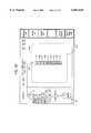
- FIGS. 4A-4Fshow a sequence of maps of a farming field which include visible indicia of a characteristic of the field displayed on an electronic display when data representative of the characteristic is being gathered and the DPU of FIG. 1 is in a panning mode of operation.
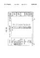
- FIGS. 5A-5Cshow a sequence of maps of a farming field which include visible indicia of a characteristic of the field displayed on an electronic display when data representative of the characteristic is being gathered and the DPU of FIG. 1 is in an automatic resealing mode of operation.
- a site-specific farming system 100preferably includes one or more core systems 102 which provide data processing functions for different agricultural vehicles including tractors and combines.
- each tractor or combineis equipped with its own core system 102.
- Each tractoris also equipped with an implement system 104 appropriate for the task at hand, and core system 102 of the tractor communicates with implement system 104 over bus 106.
- each combineis also equipped with a yield sensing system 108, and core system 102 of the combine communicates with yield sensing system 108 over bus 110.
- core system 102is removable and can be installed on a variety of agricultural vehicles.
- core system 102can be configured to operate in an "apply" mode wherein it collects, controls, records and displays application rate data.
- the displayed datamay include either the desired application rate data (e.g., the prescription map) or the actual application rate data (e.g., the sensed feedback).
- core system 102can be configured to operate in a "harvest” mode wherein it collects, records and displays harvest data (e.g., yield or moisture content).
- harvest datae.g., yield or moisture content
- Core system 102may also operate in a "scout” mode wherein it records and displays data observed and entered by an operator.
- Core system 102may also provide directional or positional assistance during scouting or when collecting soil samples. Sensing and control functions that require specialized input and output processing are performed outside core system 102.
- Farming system 100also includes a workstation or personal computer 112 which may be located in the farm office or may be portable.
- a medium of communicationis used to transfer site-specific data between core system 102 and computer 112.
- core system 102 and computer 112each include a read/write interface (not shown) for a removable memory card 114 which can be transported between core system 102 and computer 112.
- Memory cards 114may be Type II PCMCIA cards made by Centennial Technologies, Inc. However, other mediums of communication (e.g., floppy or hard disk, RF, infrared, RS-232/485 links, etc.) may be used.
- Memory card 114is used to transfer site-specific characteristic data from core system 102 to computer 112, and to transfer prescription maps from computer 112 to core system 102.
- Core system 102includes a general purpose data processing unit (DPU) 116 which communicates with the vehicle operator through a user interface 118 via links 120 (e.g., an RS-232/485 interface; a standard keyboard interface).
- DPU 116includes a processor (e.g., a 486DX or Pentium® microprocessor) and various types of memory which may include non-volatile memory (PROM, EEPROM or FLASH) and volatile memory (RAM).
- the processorexecutes a program stored in the non-volatile memory and the volatile memory (RAM) may include a battery back-up circuit.
- DPU 116may be implemented using dedicated, specific purpose equipment or hard-wired logic circuitry.
- User interface 118includes a graphical user interface (GUI) 122 providing cursor control (e.g., a mouse, joystick or four-way switch with up, down, right and left positions), assignable switches 124 (e.g., push buttons) configurable by the processor, a keyboard 125, and a voice-communication interface 126.
- GUIgraphical user interface
- DPU 116is configured to generate display signals which are applied to a reconfigurable display 128 (e.g., a CRT, flat screen LCD display) via communication link 130.
- Display 128is preferably an active-matrix LCD capable of displaying full-motion video and a number of colors under varying ambient light conditions.
- Display 128is also capable of displaying graphics and alpha-numeric characters.
- Display 128is used, inter alia, to display the current configurations of assignable switches 124.
- DPU 116, user interface 118 and display 128are located in the vehicle cab such that the operator has easy access to user interface 118 and an unobstructed view of display 128.
- Core system 102may also include a printer 132 in the cab which communicates with DPU 116 via an interface 133 (e.g., an RS-232 link).
- DPU 116receives signals representing the speed of the vehicle from ground speed sensor 134 via interface 136 (e.g., a frequency interface).
- Ground speed sensor 134may include a magnetic pickup sensor configured to sense the speed of the vehicle's wheels or transmission, or may include a radar device mounted to the body of the vehicle. The speed signals may be used by DPU 116 to calculate distance travelled as described below.
- DPU 116also communicates with a location signal generation circuit 138 which generates location signals representing the vehicle's position.
- Circuit 138may include a global positioning system (GPS) signal receiver 140 with an associated antenna 142, and a differential GPS (DGPS) signal receiver 144 with an associated antenna 146.
- GPS receiver 140may, for example, be manufactured by Trimble Navigation Ltd. of California, and DGPS receiver 144 may be manufactured by Satloc, Inc. of Arizona.
- GPS receiver 140determines longitude and latitude coordinates (and altitude) of the vehicle from signals transmitted by the GPS satellite network. The accuracy of the position data is improved by applying correction signals received by DGPS receiver 144.
- the differential correction signalsare used to correct errors present on GPS signals including the selective availability error signal added to GPS signals by the U.S. government.
- DPGS correction signalsare transmitted by the U.S. Coast Guard and by commercial services.
- the Omnistar DGPS system from John E. Chance & Assoc. of Texasincludes a network of ten land-based differential reference stations which send correction signals to a master station which uploads signals to a satellite for broadcast throughout North America.
- GPS differential correction signalsmay also be transmitted from a local base station such as the top of a building.
- DPU 116interfaces with the SATLOC L-Band Integrated TerraStar DGPS System via an RS-485 communication link.
- DPU 116communicates with implement system 104 via bus 106.
- Implement system 104may include one or more variable-rate controllers 148, variable-rate actuators 149 and application sensors 150.
- DPU 116reads application rate data for a particular field location from a prescription map (which may be supplied by computer 112), or reads an input device such as a potentiometer (not shown) used to manually set a desired application rate, and generates commands which are sent to variable-rate controllers 148.
- the command output rateis a function of the speed of the tractor and the desired application rate. For example, an increased speed will require an increased output rate to maintain a constant desired application rate.
- controllers 148In response, controllers 148 generate control signals which are applied to variable-rate actuators 149.
- Application sensors 150provide feedback signals representing the actual application rates to enable closed-loop control.
- Variable-rate application systemsinclude, for example, a variable-rate planter controller from Rawson Control Systems of Iowa and a variable-rate fertilizer spreader from Soil Teq., Inc. of Minnesota.
- Bus 106may be an RS-485 bus for a single-channel variable-rate controller, or a J-1939 implement bus for a multiple-channel controller.
- the tractormay also include site-specific sensors configured to sense characteristics of a field during field operations and communicate the information to DPU 116, even if the tractor is not equipped with variable-rate controllers.
- site-specific sensorsconfigured to sense characteristics of a field during field operations and communicate the information to DPU 116, even if the tractor is not equipped with variable-rate controllers.
- a tractor pulling a plowmay be equipped with sensors for monitoring site-specific characteristics (e.g., draft force; implement position) as a field is worked.
- site-specific characteristicse.g., draft force; implement position
- a tractor with a hitch assembly control system with various sensorsis described in U.S. Pat. No. 5,421,416, commonly assigned and incorporated herein by reference.
- a tractor, as used herein,includes various agricultural vehicles attached to implements such as planters, spreaders or fertilizers.
- yield sensing system 108typically includes a yield flow sensor 152 and a moisture sensor 154.
- Yield flow sensor 152may include an impact-type mass flow rate sensor attached to a steel plate which is struck by grain passing through the clean-grain elevator of the combine to measure the force of the grain flow.
- Moisture sensor 154may be a capacitive-type sensor mounted on the underside of the grain tank loading auger of the combine to measure the moisture content of grain passing near the sensor.
- Moisture sensor 154may include a grain temperature sensor to compensate the grain moisture signals for temperature.
- DPU 116receives sensed signals from flow sensor 152 and moisture sensor 154, and receives location signals from location signal generation circuit 138 which represent the positions of the combine where grain flow and moisture content were sampled.
- the grain flow and moisture content signalsare processed to form data representative of the respective characteristic, and this data is correlated with location data representative of the location signals. Correlated data is stored in memory card 114 or in another memory.
- the distance travelled by the combineis determined by multiplying the combine's speed by elapsed time.
- the speedmay be based upon signals sensed by speed sensor 134, or may be determined by calculating the difference between successive position signals received from location signal generation circuit 138 and dividing by elapsed time.
- the yielde.g., bu/acre
- the yieldis determined by dividing the quantity of sensed grain (e.g., bu) by the area of the field harvested (e.g., acres), wherein the quantity of sensed grain is the product of the grain flow rate and time, and the area is the product of the width of cut and distance travelled.
- DPU 116receives RS-485 serial communication signals from a yield module unit (YMU) 155 which is configured to perform data processing for yield sensing system 108. Using a separate YMU off-loads data processing functions from DPU 116, and minimizes wiring between the combine and the DPU.
- YMU 155receives sensed signals from flow sensor 152, moisture sensor 154, a header up/down sensor 156, an elevator speed sensor 158 and a ground speed sensor 160. Header up/down sensor 156 senses the position of the combine's header to detect whether the combine is harvesting. When header position is above a pre-programmed value, YMU 155 assumes the combine is not harvesting and yield information is not calculated.
- Elevator speed sensor 158senses the speed of the clean grain elevator to determine the speed at which grain passes through the elevator. Signals from sensor 158 may be used to compensate the yield calculations for the delay before harvested grain is sensed.
- Ground speed sensor 160senses ground speed of the combine, and may be the same as ground speed sensor 134, or similar to it.
- YMU 155uses signals from sensors 152, 154, 156, 158 and 160 to calculate and communicate yield and moisture content data to DPU 116 via bus 110.
- the update rate at which data is communicatedmay be once per second.
- YMU 155may provide instantaneous yield and moisture content data, and may also provide field and load total (summary) values for grain weight, wet and dry bushels, average moisture, area harvested and dry yield.
- YMU 155allows specific yield processing functions to be moved from DPU 116.
- YMU 155may send raw sensed data to DPU 116 and the DPU may perform the calculations.
- farming system 100could also be configured such that DPU 116 reads the signals directly from the sensors.
- Core system 102may communicate with other vehicle systems over a vehicle data bus (not shown).
- vehicle data busconforms to the standards of SAE J-1939 ("Recommended Practice for a Serial Control and Communications Vehicle Network").
- a bridge circuitmay be used to facilitate the transfer of data between the vehicle data bus and a secondary implement bus coupled to implement system 104 and DPU 116.
- the bridge circuitmay be used to filter data between busses, thereby decreasing bus loading.
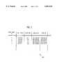
- FIG. 2generally represents the structure in which a layer of site-specific data representing a characteristic of a farming field is stored in memory.
- the structuremay be referred to as a georeferenced digital map, or a layer of data.
- the structureis preferably implemented using a database 200 (e.g., a geographical information system (GIS) database) represented by the table shown in FIG. 2, wherein each row represents a characteristic data point taken at a location in the field.
- GISgeographical information system
- a layer having 5000 data pointsis represented by a table having 5000 rows. Columns of information are associated with each data point.
- the columns shown in FIG. 2include yield data (bu/acre), moisture content, and the longitude and latitude coordinates at which each data point was sampled.
- Additional columnsmay include flow rate, GPS time, combine serial number (S/N), field identification, type of grain (e.g., corn), and altitude.
- the data structure of FIG. 2represents, for example, a yield layer.
- Data in the first rowindicates that flow sensor 152 and moisture sensor 154 of the combine sensed grain flow corresponding to a yield of 32.0739 bu/acre and a moisture content of 17.7, respectively, at a location defined by longitude and latitude coordinates -88.7291520 and 39.0710720.
- Similar structuresmay be used to store other layers of data.
- a pH layermay include a row for each data point and columns for pH, longitude and latitude.
- DPU 116uses the characteristic data and correlated location data to generate display signals which cause display 128 to plot a map of a field which includes visible indicia of the characteristic.
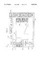
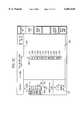
- the screen 300 of electronic display 128includes a map display area 302, a graphical operator interface 304 to show the current configuration of assignable switches 124, a legend block 306, a status block 308 for displaying statistical data (average yield and moisture content) of the field, a compass indicator 310 to show the heading of the vehicle, a map scale 312, and a status line 314 for displaying status information such as operating mode ("harvest” or "apply"), vehicle speed, time remaining until memory card 114 is full, GPS and DGPS status (e.g., good or bad) and date/time.
- the graphical symbols and their positions within screen 200are shown for illustration only and may be modified.
- map display area 302may cover any portion or all of screen 300, with other displayed information superimposed or suppressed if necessary.
- FIG. 3represents an exemplary display when core system 102 is mounted on a combine equipped with yield flow sensor 152 and moisture sensor 154, and the combine is harvesting grain.
- the boundaries of the field being harvestedare defined and are stored in memory.
- DPU 116accesses the longitude and latitude coordinates of the field boundary from memory and scales the field boundary to substantially correspond to a portion of map display area 302.
- DPU 116scales the boundary data and produces display signals which, when applied to display 128, generate a visible map 316 of the field within the portion of the map display area 302.
- the portion of map display area 302 which is used to display map 316may be 80%, 85% or 90% of the size of map display area 302, with the percentage selected to enhance the visual appearance of map 316. However, any percentage value may be used which provides a desirable appearance, including 100%, and the percentage may be set by the user.
- the scale of map 316is displayed at map scale 312 (e.g. 100 ft/inch).
- the combinewas located at the upper-right hand corner of map 316.
- the combinethen made a number of passes through the field, turning at the headlands (located at the boundaries of map 316).
- the current location of the combineis marked by an icon 318, such as an arrow which also indicates the direction of travel which may be determined from changes in the location data.
- iconsmay be used (e.g., a drawing of a combine).
- DPU 116gathers site-specific data sensed by flow sensor 152 and moisture sensor 154 and correlates the sensed data with the locations at which the sensed data was sampled using signals from location signal generation circuit 138. Thedata may be sampled, for example, at 1 second intervals.
- the correlated datais stored in memory (e.g., memory card 114) for later analysis by office computer 112.
- DPU 116may be configured to not calculate yield data based upon an indication that the combine is not harvesting (e.g., header position is above a threshold position).
- DPU 116provides an indication of the time remaining before memory card 114 is filled up by yield data during "harvest” mode, or by actual application rate data during "apply” mode when core system 102 is on a tractor.
- the time remainingequals the amount of memory currently free multiplied by the time since the start of harvesting or application, divided by the difference between the amount of memory free at the start and the amount of memory currently free.
- the result of the calculationis displayed in status line 314 (e.g., "10.3 Hours Until Card is Full").
- DPU 116may display the portion or percentage of memory card 114 filled up.
- DPU 116may also provide an indication of the estimated time remaining until sampling of the field is complete (i.e., estimated time to complete harvesting or application).
- the estimated time to completeequals the time since the start of harvesting or application multiplied by the difference between the area of map 316 within the boundaries and the area harvested, divided by the area harvested.
- the resultis displayed on display 128 (e.g., "Estimated Time to Complete is 3.5 Hours").
- DPU 116may display the portion or percentage of the field that has been worked.
- DPU 116is preferably programmed with variables, which may be set by the operator, which indicate the distance and direction between GPS antenna 142 and the sampled location of the field (i.e., between antenna 142 and the combine's header or the tractor's implement). This information is used as an offset to correct the location data stored with the sensed data. Also, to compensate for the time required for grain entering the header of the combine to reach flow sensor 152, DPU 116 is programmed with a delay value (e.g., 10 seconds). Sensed data is correlated with the location data received 10 seconds earlier. Thus, no data will be sensed and no data will be plotted until 10 seconds after harvesting starts. In one embodiment, DPU 116 maintains a buffer of the last 20 positions received, and selects a position to use based upon the delay value.
- variableswhich may be set by the operator, which indicate the distance and direction between GPS antenna 142 and the sampled location of the field (i.e., between antenna 142 and the combine's header or the tractor's implement). This information
- the characteristic data and correlated location dataare used to produce a display signal in real-time which, when applied to display 128, generates visible indicia of the characteristic data at corresponding locations of map 316.
- DPU 116gathers characteristic data over "square" areas of the field where the sides of the square are substantially equal to the width of cut of the combine (or the width of the implement). Other shapes or blocks could also be used such as rectangles where the width is equal to the width of cut and the length is equal to the distance traversed in some time interval. Data within each block is automatically processed or filtered (e.g., averaged). Averaging data as it is plotted eliminates the need to plot every data point, thereby decreasing visual noise on display 128.
- the blocks of datacould be stored in memory rather than the raw data to reduce the memory storage and subsequent processing requirements.
- the average value of the data in each block, and location data associated with the block (appropriately scaled),are used to produce the display signal applied to display 128.
- display 128generates visible blocks 320 which include visible indicia of the average characteristic value at corresponding locations of map 316.
- Characteristic datamay be visually represented on display 128 in several ways.
- distinguishable colorsrepresent different ranges of the average data in each visible block.
- the colors red, orange, yellow, green, cyan, blue and violetmay represent increasing ranges of average yield.
- Legend 306displays each color and its associated yield range: below 25 (red); 25-49 (orange); 50-74 (yellow); 75-99 (green); 100-124 (cyan); 125-150 (blue); and above 150 bu/acre of corn (violet).
- the default colors and rangesare: 0-7% (red); 7-14% (orange); 14-21% (yellow); 21-28% (green); 29-35% (cyan); 35-42% (blue); and above 42% (violet).
- the ranges and colorscould also be selectable by the user.
- the userselects an average value of the characteristic for the field and the ranges are based on the average value, with green centered at the average.
- each colormay represent a yield range of 5 bu/acre if the selected average yield is 50 bu/acre or less, a range of 10 bu/acre if the selected average yield is 50 to 125 bu/acre, or a range of 15 bu/acre if the selected average yield is 125 bu/acre or more.
- rangesmay be represented by alpha-numeric characters or by different light intensity levels or grey scales.
- Graphical operator interface 304includes a label which shows the assignment currently selected for each switch 124. The label and assignment depend on the mode of operation of DPU 116.
- Indicator 310is an electronic compass which shows the current direction or heading of the vehicle with respect to north (e.g., northeast in FIG. 3).
- DPU 116may calculate the heading based on a vector from the previous location of the vehicle to the current location. Appropriate filtering should be used to keep the compass from changing direction due to GPS errors when the vehicle is not moving.
- the vehiclemay be equipped with a compass or gyroscope electronically interfaced with DPU 116.
- the orientation of the displayshows the vehicle going up and down as it travels northeast. However, the orientation of the display could also be geographic (e.g., north up).
- core system 102can generate visual maps of a field which may be preferable to the operator in certain situations. For example, in a large field which requires an agricultural vehicle to make many passes, the size of data blocks 320 may become very small due to scaling if display 128 shows the entire field. The small size may make it difficult to monitor the sensed characteristic as the field is worked. Even if the data blocks are relatively large compared to the size of the field, as in FIG. 3, much of the display screen remains blank until corresponding data is gathered. Blank space does not provide characteristic information and does not make optimum use of screen 300. In addition, it may be difficult to determine the scale factor to use when the map borders are undefined and not available for scaling the location data.
- core system 102provides alternative formats for displaying characteristic data in real-time as it is being gathered.
- the first alternative formatreferred to as “panning” is illustrated by the sequence of maps shown in FIGS. 4A-4F and the second alternative format, referred to as “auto resealing", is illustrated by the sequence of maps shown in FIGS. 5A-5C.
- the displayed mapis dynamically changed to keep the vehicle on the display screen.
- each map sequenceis described in relation to plotting a yield map as a field of grain is harvested. However, the sequence is similar for other characteristic data (e.g., moisture content) which may be selected by the user.
- other characteristic datae.g., moisture content
- an operator input to DPU 116indicates that harvest is about to begin.
- the operatormay, if desired, enter a farm name and field name into DPU 116 to label the field being harvested.
- DPU 116generates display signals which, when applied to electronic display 128, generates icon 318 substantially at the center of map display area 302.
- the center positioncorresponds to the current location of the vehicle determined from location signals received from location signal generation circuit 138.
- the scale of the mapis set to a default value (e.g., 50 ft/inch) shown by map scale 312.
- the combinehas traveled to the location in the field represented by icon 318.
- the combinehas traveled a distance equal to three times the width of cut and yield data received from flow sensor 152 has been processed and correlated with location data for three blocks 410, 411 and 412 of data.
- Average yield data for first block 410 and third block 412was in the range of 25-49 bu/acre and the average yield for the second block 411 was below 25 bu/acre.
- the color for each blockwas computed by comparing the average yield for the block with the yield ranges for the colors.
- the comparison resultscaused DPU 116 to produce display signals which, when applied to display 128, have caused display 128 to draw an orange block, red block, and orange block, respectively, along the path of travel.
- DPU 116allows a user to change the scale (e.g., between 50, 100, 200, 400, etc. ft/inch) by configuring assignable switches 124 to include a ZOOM IN switch 400 and a ZOOM OUT switch 402.
- Each actuation of ZOOM IN switch 400decreases the map scale by a fraction (e.g., multiply by 1/2).
- Each actuation of ZOOM OUT switch 402increases the scale by the inverse of the fraction (e.g., multiply by 2).
- the maximum zoomed in viewis limited to a certain scale (e.g., 50 ft/inch).
- a certain scalee.g., 50 ft/inch.
- an actuation of ZOOM IN switch 400would change the scale from 100 to 50 ft/inch and the size of each block 410-412 would double.
- a subsequent actuation of ZOOM OUT switch 402would switch the scale back to 100 ft/inch and the size of each block would revert to its original size.
- Block 414is the last block of data that can be plotted inside of an invisible rectangular region 404 preferably centered in map display area 302, and icon 318 shows that the combine has just moved outside of region 404.
- Region 404covers a portion of map display area 302, such as 80, 85, 90 or even 100%. Since the vehicle is still traveling in the same direction, as shown by icon 318, region 404 has no room for another block.
- the map of the field represented by blocks 411-415is redrawn such that icon 318 is again centered in map display area 302.
- DPU 116recalculates the boundaries of the area that will be displayed such that the current location is centered.
- the mapis not rescaled in the panning display format (see scale 312).
- first data block 410is no longer displayed since it is mapped outside of the display area.
- the combinehas continued to travel and has again begun to move outside of region 404.
- Four new data blocks 416-419have been processed and plotted.
- FIG. 4Fthe combine moved outside region 404 in FIG. 4E, and the map represented by the data blocks has been redrawn such that icon 318 is again centered in map display area 302. Again, the scale of the map has not changed (see scale 312).
- a new data block 420is displayed but data blocks which no longer correspond with map display area 302, such as blocks 411-415, are no longer displayed.
- the panning formatis used whenever the vehicle leaves region 404 regardless of direction. Also, if the vehicle were to turn around, data blocks which had been displayed previously will reappear as the vehicle reaches nearby locations.
- the displayed mapremains relatively stationary since it is redrawn only when the vehicle moves beyond region 404. This is advantageous compared with a display system which always keeps the vehicle centered on the map since such a map must be constantly redrawn.
- the stability of the mapdecreases the computation needed to redraw the map, and makes the map easier to view since it is not constantly being redrawn and is not constantly shifting.
- Core system 102remains in the panning mode until the user zooms out to the maximum zoom out where all the data is displayed on the map.
- the mapis drawn using a custom scaling such that the displayed map uses some portion of the map display area, such as 80, 85, 90 or even 100% of the map display area.
- the systemswitches into the automatic resealing display format.
- an operatorcould select the automatic resealing display format at the start of the harvest.
- the automatic resealing display formatis explained in reference to FIGS. 5A-5C. As stated above, automatic resealing is used when all the gathered data is displayed (i.e., in maximum zoom out).
- the combineis making a first pass through the field and is at the location in the field represented by icon 318.
- map scale 312a default scale of 50 ft/inch is used.
- Core system 102has plotted blocks of data 510-520 along the path of the combine on display 128.
- the combineis at a location in the field which substantially corresponds to a border 500 of map display area 302 (i.e., the location is at or close to border 500, such as within 10, 15 or 20% of the border).
- a new data block 521(not shown in FIG. 5B) has been processed and is ready to be plotted, but there is no room for block 521 in map display area 302.
- DPU 116responds by resealing the geographic area defined by blocks 510-521 such that the map represented by blocks 510-521 appears smaller by some percentage (e.g., 20%).
- the rescaled or resized mapis displayed and centered in map display area 302. As shown by map scale 312, the map was automatically resized or rescaled from 50 ft/inch to 60 ft/inch (e.g., 20%).
- the automatic resealing display formatis used until ZOOM IN switch 400 is actuated. At this point, all of the selected data can no longer be displayed. Thus, the map is rescaled to the next smallest allowed distance (e.g., 500, 1000, 2000, etc. and ft./inch) around the vehicle and the panning format is used.
- the next smallest allowed distancee.g., 500, 1000, 2000, etc. and ft./inch
- the system described hereinmay also be used to draw maps of moisture content or other site-specific data collected during harvesting.
- the systemmay also be used to draw a map of other site-specific characteristic data in the cab of a tractor or other agricultural vehicle.
- the systemmay be used to draw a map showing the actual or the desired application rate of fertilizer, herbicide, water, insecticide or seed when operated in "apply" mode on a tractor.
- Other site-specific map datamay include soil type, soil fertility, soil moisture content, soil compaction, pH, crop height, insect or weed infestation, landmarks, field borders or topography (e.g., altitude).
- Soil compactionfor example, may be measured by sensing draft force exerted by the ground on an implement such as a plow, and correcting for the plow's depth using a position signal.
Landscapes
- Engineering & Computer Science (AREA)
- Radar, Positioning & Navigation (AREA)
- Remote Sensing (AREA)
- Life Sciences & Earth Sciences (AREA)
- Soil Sciences (AREA)
- General Physics & Mathematics (AREA)
- Physics & Mathematics (AREA)
- Mechanical Engineering (AREA)
- Automation & Control Theory (AREA)
- Environmental Sciences (AREA)
- Management, Administration, Business Operations System, And Electronic Commerce (AREA)
- Guiding Agricultural Machines (AREA)
- Navigation (AREA)
- Position Fixing By Use Of Radio Waves (AREA)
- Radio Relay Systems (AREA)
- Radar Systems Or Details Thereof (AREA)
Abstract
Description
Claims (33)
Priority Applications (1)
| Application Number | Priority Date | Filing Date | Title |
|---|---|---|---|
| US09/335,360US6061618A (en) | 1996-11-22 | 1999-06-17 | Panning display of GPS field maps |
Applications Claiming Priority (2)
| Application Number | Priority Date | Filing Date | Title |
|---|---|---|---|
| US08/754,926US5938709A (en) | 1996-11-22 | 1996-11-22 | Panning display of GPS field maps |
| US09/335,360US6061618A (en) | 1996-11-22 | 1999-06-17 | Panning display of GPS field maps |
Related Parent Applications (1)
| Application Number | Title | Priority Date | Filing Date |
|---|---|---|---|
| US08/754,926ContinuationUS5938709A (en) | 1996-11-22 | 1996-11-22 | Panning display of GPS field maps |
Publications (1)
| Publication Number | Publication Date |
|---|---|
| US6061618Atrue US6061618A (en) | 2000-05-09 |
Family
ID=25036977
Family Applications (2)
| Application Number | Title | Priority Date | Filing Date |
|---|---|---|---|
| US08/754,926Expired - LifetimeUS5938709A (en) | 1996-11-22 | 1996-11-22 | Panning display of GPS field maps |
| US09/335,360Expired - LifetimeUS6061618A (en) | 1996-11-22 | 1999-06-17 | Panning display of GPS field maps |
Family Applications Before (1)
| Application Number | Title | Priority Date | Filing Date |
|---|---|---|---|
| US08/754,926Expired - LifetimeUS5938709A (en) | 1996-11-22 | 1996-11-22 | Panning display of GPS field maps |
Country Status (6)
| Country | Link |
|---|---|
| US (2) | US5938709A (en) |
| EP (1) | EP0952766B1 (en) |
| AR (1) | AR011281A1 (en) |
| AU (1) | AU719575B2 (en) |
| DE (1) | DE69723868T2 (en) |
| WO (1) | WO1998021927A1 (en) |
Cited By (47)
| Publication number | Priority date | Publication date | Assignee | Title |
|---|---|---|---|---|
| WO2001052160A1 (en)* | 2000-01-14 | 2001-07-19 | Ag-Chem Equipment Company, Inc. | Application report and method for creating the same |
| US20010026271A1 (en)* | 2000-03-29 | 2001-10-04 | Higgins Darin Wayne | System and method for synchronizing raster and vector map images |
| US20010033290A1 (en)* | 2000-03-29 | 2001-10-25 | Scott Dan Martin | System and method for georeferencing digial raster maps |
| US6327569B1 (en)* | 1998-10-15 | 2001-12-04 | Milestone Technology, Inc. | System and methods for real time linkage between harvest environment and marketplace |
| US6336066B1 (en)* | 1998-09-29 | 2002-01-01 | Pellenc S.A. | Process for using localized agricultural data to optimize the cultivation of perennial plants |
| US6356830B1 (en)* | 1998-08-11 | 2002-03-12 | Purdue Research Foundation | System and method for automated measurement of soil pH |
| US6516271B2 (en) | 2001-06-29 | 2003-02-04 | The Regents Of The University Of California | Method and apparatus for ultra precise GPS-based mapping of seeds or vegetation during planting |
| US6522948B1 (en)* | 2000-08-14 | 2003-02-18 | Flexi-Coil Ltd. | Agricultural product application tracking and control |
| US6553312B2 (en) | 2001-06-29 | 2003-04-22 | The Regents Of The University Of California | Method and apparatus for ultra precise GPS-based mapping of seeds or vegetation during planting |
| US6597992B2 (en) | 2001-11-01 | 2003-07-22 | Soil And Topography Information, Llc | Soil and topography surveying |
| US6651005B2 (en)* | 2000-09-25 | 2003-11-18 | O'neall Donald L. | Method for establishing universal standards for yield measurement |
| WO2004003301A1 (en)* | 2002-07-01 | 2004-01-08 | Compaction Technology (Soil) Ltd | Drop mass compaction of soil |
| WO2004012494A1 (en)* | 2002-07-26 | 2004-02-12 | Cnh Belgium Nv | Methods of optimising stochastic processing parameters in crop harvesting machines |
| US6748884B1 (en) | 2003-06-03 | 2004-06-15 | Case, Llc | Automatic liquid fertilizer rate system |
| US20050073532A1 (en)* | 2000-03-29 | 2005-04-07 | Scott Dan Martin | System and method for georeferencing maps |
| US20050150160A1 (en)* | 2003-10-28 | 2005-07-14 | Norgaard Daniel G. | Method for selecting crop varieties |
| US6956590B1 (en)* | 2001-02-28 | 2005-10-18 | Navteq North America, Llc | Method of providing visual continuity when panning and zooming with a map display |
| EP1650715A1 (en)* | 2004-09-30 | 2006-04-26 | CLAAS Selbstfahrende Erntemaschinen GmbH | Scalable function window in a display unit |
| US20070068238A1 (en)* | 2005-09-27 | 2007-03-29 | Cnh America Llc | Tire inflation system for use with an agricultural implement |
| US20070087828A1 (en)* | 2005-10-14 | 2007-04-19 | Alexander Robertson | Computer system for creating and playing location aware games |
| US20070089390A1 (en)* | 2005-10-25 | 2007-04-26 | Hendrickson Larry L | Crop attribute map input for vehicle guidance |
| US20080015770A1 (en)* | 2004-06-15 | 2008-01-17 | Xanavi Informatics Corporation | Map Data Providing Method |
| US20080091520A1 (en)* | 2004-11-04 | 2008-04-17 | Keiji Hatori | Work Management System and Working Machine Equipped With the Same |
| US20080127905A1 (en)* | 2006-12-01 | 2008-06-05 | Gmv Aerospace And Defence S.A. | System and a method for determining the region searched by a moving scent detector (organ or apparatus) in the presence of wind |
| US20080275609A1 (en)* | 2007-05-01 | 2008-11-06 | Broughton Boydell | Automatic steering system and method for a work vehicle with feedback gain dependent on a sensed payload |
| US20090208296A1 (en)* | 2004-11-29 | 2009-08-20 | Compaction Technology (Proprietary) Ltd. | Drop mass soil compaction apparatus |
| US7908062B2 (en) | 2007-02-28 | 2011-03-15 | Caterpillar Inc. | System and method for preparing a worksite based on soil moisture map data |
| US8028450B2 (en) | 2008-07-31 | 2011-10-04 | Typenex Medical, Llc | Recipient verification systems and methods of use including recipient identification |
| US20120240421A1 (en)* | 2010-12-28 | 2012-09-27 | Agco Corporation | Field Productivity Gauge |
| US8412419B1 (en) | 2009-09-17 | 2013-04-02 | Helena Chemical Company | System for mapping GIS layers |
| US20130184944A1 (en)* | 2010-07-14 | 2013-07-18 | Bart M.A. Missotten | Method and device for predictive control of agricultural vehicle systems |
| US20130311050A1 (en)* | 2012-05-15 | 2013-11-21 | Trimble Navigation Limited | Agricultural Rate Management |
| US8635903B2 (en) | 2009-12-22 | 2014-01-28 | Caterpillar Paving Products Inc. | Method and system for compaction measurement |
| WO2014130192A1 (en)* | 2013-02-20 | 2014-08-28 | Deere & Company | Crop sensing display |
| US8827001B2 (en) | 2012-01-17 | 2014-09-09 | Cnh Industrial America Llc | Soil monitoring system |
| US9320196B2 (en) | 2013-02-20 | 2016-04-26 | Deere & Company | Stripper plate adjustment |
| US10039231B2 (en)* | 2015-05-19 | 2018-08-07 | Deere & Company | System for measuring plant attributes using a priori plant maps |
| US10178828B2 (en) | 2013-02-20 | 2019-01-15 | Deere & Company | Per plant crop sensing resolution |
| US10194574B2 (en) | 2016-11-18 | 2019-02-05 | Cnh Industrial America Llc | System for adjusting smoothing tools of a harrow according to location |
| US10918008B2 (en) | 2018-11-30 | 2021-02-16 | Cnh Industrial America Llc | System and method for generating a prescription map for an agricultural implement based on soil compaction |
| US11001380B2 (en) | 2019-02-11 | 2021-05-11 | Cnh Industrial Canada, Ltd. | Methods for acquiring field condition data |
| US11059582B2 (en) | 2019-02-11 | 2021-07-13 | Cnh Industrial Canada, Ltd. | Systems for acquiring field condition data |
| US11064645B2 (en) | 2018-10-16 | 2021-07-20 | Cnh Industrial America Llc | System and method for controlling operation of a work vehicle towing an agricultural implement |
| US11212962B2 (en) | 2013-02-20 | 2022-01-04 | Deere & Company | Field condition determination |
| US11337359B2 (en)* | 2017-06-02 | 2022-05-24 | Cnh Industrial America Llc | Ground bearing capacity |
| US11570944B1 (en)* | 2021-08-31 | 2023-02-07 | Hainan University | Automatic row-guiding method for maize combine harvester based on situation of missing plants |
| US12016257B2 (en) | 2020-02-19 | 2024-06-25 | Sabanto, Inc. | Methods for detecting and clearing debris from planter gauge wheels, closing wheels and seed tubes |
Families Citing this family (53)
| Publication number | Priority date | Publication date | Assignee | Title |
|---|---|---|---|---|
| GB9520478D0 (en)* | 1995-10-06 | 1995-12-06 | West Glamorgan County Council | Monitoring system |
| US5938709A (en)* | 1996-11-22 | 1999-08-17 | Case Corporation | Panning display of GPS field maps |
| US6070673A (en)* | 1996-11-22 | 2000-06-06 | Case Corporation | Location based tractor control |
| DE19706614A1 (en)* | 1997-02-20 | 1998-08-27 | Claas Ohg | Situation-related program-controlled electronic map image display in a motor vehicle |
| US5959257A (en)* | 1998-04-15 | 1999-09-28 | Harvestmaster, Inc. | System for weighing material on a conveyor |
| DE19844615C2 (en)* | 1998-09-29 | 2003-02-20 | Deutsch Zentr Luft & Raumfahrt | Method for determining and geocoding a fertility map of soil surfaces and device for carrying out the method |
| US6115481A (en) | 1998-10-22 | 2000-09-05 | Centrak, Llc | User modifiable land management zones for the variable application of substances thereto |
| DE19855807B4 (en)* | 1998-12-03 | 2004-07-08 | Volker Hegewald | Soil sampling method |
| US6505146B1 (en)* | 1999-09-24 | 2003-01-07 | Monsanto Company | Method and system for spatial evaluation of field and crop performance |
| US6898559B2 (en)* | 2000-12-08 | 2005-05-24 | Tracker R&D, Llc | System for dynamic and automatic building mapping |
| FR2820509B1 (en)* | 2001-02-07 | 2004-05-14 | Univ Paris Curie | METHOD FOR PROCESSING GEOREFERENCED ELECTRICAL RESISTIVITY MEASUREMENTS FOR ELECTRICAL MAPPING OF SOILS IN REAL TIME |
| CA2356575C (en)* | 2001-08-31 | 2004-07-13 | Bourgault Industries Ltd. | Zone control for agricultural product application |
| JP2003263104A (en)* | 2002-03-11 | 2003-09-19 | Mitsubishi Electric Corp | Imaging information recognition system |
| US7103451B2 (en) | 2002-08-19 | 2006-09-05 | Intime, Inc. | Method and system for spatially variable rate application of agricultural chemicals based on remotely sensed vegetation data |
| US6813544B2 (en) | 2002-08-19 | 2004-11-02 | Institute Of Technology Development | Method and apparatus for spatially variable rate application of agricultural chemicals based on remotely sensed vegetation data |
| DE10250694B3 (en)* | 2002-10-31 | 2004-02-12 | CNH Österreich GmbH | Agricultural vehicle control method provides automatic travel and field end management by detection, storage and controlled alteration of vehicle operating parameters |
| CN100535601C (en)* | 2004-03-19 | 2009-09-02 | 日本先锋公司 | Portable information processor |
| US7865301B2 (en)* | 2004-03-23 | 2011-01-04 | Google Inc. | Secondary map in digital mapping system |
| US7831387B2 (en)* | 2004-03-23 | 2010-11-09 | Google Inc. | Visually-oriented driving directions in digital mapping system |
| WO2005104039A2 (en)* | 2004-03-23 | 2005-11-03 | Google, Inc. | A digital mapping system |
| US7620496B2 (en)* | 2004-03-23 | 2009-11-17 | Google Inc. | Combined map scale and measuring tool |
| US7599790B2 (en)* | 2004-03-23 | 2009-10-06 | Google Inc. | Generating and serving tiles in a digital mapping system |
| US7933897B2 (en) | 2005-10-12 | 2011-04-26 | Google Inc. | Entity display priority in a distributed geographic information system |
| US7917286B2 (en)* | 2005-12-16 | 2011-03-29 | Google Inc. | Database assisted OCR for street scenes and other images |
| US20070282812A1 (en)* | 2006-03-08 | 2007-12-06 | Superior Edge, Inc. | Process execution support system |
| US7313478B1 (en)* | 2006-06-08 | 2007-12-25 | Deere & Company | Method for determining field readiness using soil moisture modeling |
| US7591226B2 (en)* | 2006-11-03 | 2009-09-22 | Cnh America Llc | Automatic path generation for tramlines |
| US8478515B1 (en) | 2007-05-23 | 2013-07-02 | Google Inc. | Collaborative driving directions |
| US8359139B2 (en)* | 2008-09-15 | 2013-01-22 | Cnh America Llc | Method and system for vehicle orientation measurement |
| US8463510B2 (en) | 2010-04-30 | 2013-06-11 | Cnh America Llc | GPS controlled residue spread width |
| US9213905B2 (en) | 2010-10-25 | 2015-12-15 | Trimble Navigation Limited | Automatic obstacle location mapping |
| US10115158B2 (en) | 2010-10-25 | 2018-10-30 | Trimble Inc. | Generating a crop recommendation |
| US9058633B2 (en) | 2010-10-25 | 2015-06-16 | Trimble Navigation Limited | Wide-area agricultural monitoring and prediction |
| US9846848B2 (en) | 2010-10-25 | 2017-12-19 | Trimble Inc. | Exchanging water allocation credits |
| US9408342B2 (en) | 2010-10-25 | 2016-08-09 | Trimble Navigation Limited | Crop treatment compatibility |
| US9058560B2 (en) | 2011-02-17 | 2015-06-16 | Superior Edge, Inc. | Methods, apparatus and systems for generating, updating and executing an invasive species control plan |
| CN103930919A (en)* | 2011-10-24 | 2014-07-16 | 天宝导航有限公司 | Agricultural and soil management |
| US9551980B2 (en)* | 2011-11-09 | 2017-01-24 | Lonestar Inventions, L.P. | Solar timer using GPS technology |
| US9113590B2 (en) | 2012-08-06 | 2015-08-25 | Superior Edge, Inc. | Methods, apparatus, and systems for determining in-season crop status in an agricultural crop and alerting users |
| GB2510629B (en) | 2013-02-11 | 2015-10-14 | Kverneland Group Les Landes Genusson | Strip tilling system |
| US8849523B1 (en) | 2013-05-20 | 2014-09-30 | Elwha Llc | Systems and methods for detecting soil characteristics |
| US10373353B2 (en)* | 2013-10-31 | 2019-08-06 | Trimble Inc. | Crop yield data adjustments |
| JP6162582B2 (en)* | 2013-11-18 | 2017-07-12 | 株式会社クボタ | Agricultural support system |
| US9489576B2 (en) | 2014-03-26 | 2016-11-08 | F12 Solutions, LLC. | Crop stand analysis |
| EP2980669B1 (en)* | 2014-08-01 | 2017-09-20 | AGCO Corporation | Determining field characterisitics using optical recognition |
| US9652840B1 (en) | 2014-10-30 | 2017-05-16 | AgriSight, Inc. | System and method for remote nitrogen monitoring and prescription |
| US20170115833A1 (en)* | 2015-10-27 | 2017-04-27 | Cnh Industrial America Llc | Top bar display for an agricultural system |
| US11096323B2 (en)* | 2017-04-18 | 2021-08-24 | CropZilla Software, Inc. | Machine control system providing actionable management information and insight using agricultural telematics |
| US11582903B1 (en)* | 2017-05-17 | 2023-02-21 | Hydro-Gear Limited Partnership | Vision based guidance system and method for lawn mowing devices |
| US10776733B2 (en) | 2017-06-26 | 2020-09-15 | Acuitus Ag, Inc. | Computer platform for controlling agricultural assets |
| US10860189B2 (en)* | 2018-01-11 | 2020-12-08 | Precision Planting Llc | Systems and methods for customizing scale and corresponding views of data displays |
| DE102018009344A1 (en)* | 2018-11-29 | 2020-06-04 | Bomag Gmbh | METHOD FOR CARRYING OUT A SURFACE-WIDE, DYNAMIC COMPRESSION CONTROL OF A SOIL COMPRESSION MACHINE USING A MOBILE COMPONENT, SOIL COMPRESSION MACHINE AND SYSTEM, INCLUDING AT LEAST TWO BOTTOM COMPRESSIONS |
| CN110542914B (en)* | 2019-09-10 | 2023-03-10 | 江西理工大学 | A 3S seamlessly integrated field dynamic inspection method for land law enforcement |
Citations (34)
| Publication number | Priority date | Publication date | Assignee | Title |
|---|---|---|---|---|
| US35100A (en)* | 1862-04-29 | Improvement in windmills | ||
| EP0120487A2 (en)* | 1983-03-25 | 1984-10-03 | Nippondenso Co., Ltd. | Map display system for vehicles |
| US4578678A (en)* | 1983-11-14 | 1986-03-25 | The United States Of America As Represented By The United States National Aeronautics And Space Administration | High dynamic global positioning system receiver |
| US4630773A (en)* | 1984-11-06 | 1986-12-23 | Soil Teq., Inc. | Method and apparatus for spreading fertilizer |
| US4675676A (en)* | 1983-03-09 | 1987-06-23 | Nippondenso Co. Ltd. | Map display system |
| US4736303A (en)* | 1985-04-09 | 1988-04-05 | Mitsubishi Denki Kabushiki Kaisha | On-vehicle navigation system |
| US4792907A (en)* | 1986-11-17 | 1988-12-20 | Nippondenso Co., Ltd. | Vehicle navigation system |
| US4949268A (en)* | 1987-09-22 | 1990-08-14 | Kabushiki Kaisha Toyota Chuo Kenkyusho | Land vehicle navigation system |
| US5084822A (en)* | 1987-12-15 | 1992-01-28 | Mitsubishi Denki Kabushiki Kaisha | Navigation apparatus for moving object |
| US5214757A (en)* | 1990-08-07 | 1993-05-25 | Georesearch, Inc. | Interactive automated mapping system |
| US5220509A (en)* | 1990-04-27 | 1993-06-15 | Pioneer Electronic Corporation | Vehicle navigation apparatus |
| EP0576121A1 (en)* | 1992-06-22 | 1993-12-29 | Ag-Chem Equipment Co., Inc. | Variable rate application system |
| US5282389A (en)* | 1992-09-16 | 1994-02-01 | Dawn Equipment Company | Apparatus for measuring agricultural yield |
| WO1995002318A2 (en)* | 1993-07-17 | 1995-01-26 | Duerrstein Georg | Process for working exploitable territories |
| US5396431A (en)* | 1991-10-22 | 1995-03-07 | Pioneer Electronic Corporation | Navigation system with position measuring device and aerial photographic storage capability |
| US5398034A (en)* | 1993-03-29 | 1995-03-14 | Stanford Telecommunications, Inc. | Vector delay lock loop processing of radiolocation transmitter signals |
| US5416712A (en)* | 1993-05-28 | 1995-05-16 | Trimble Navigation Limited | Position and velocity estimation system for adaptive weighting of GPS and dead-reckoning information |
| US5421416A (en)* | 1993-09-08 | 1995-06-06 | Case Corporation | Hitch assembly control system |
| US5428544A (en)* | 1990-11-05 | 1995-06-27 | Norm Pacific Automation Corporation | Traffic information inter-vehicle transference and navigation system |
| US5440484A (en)* | 1992-05-15 | 1995-08-08 | Zexel Corporation | Calibration method for a relative heading sensor |
| US5452211A (en)* | 1992-08-10 | 1995-09-19 | Caterpillar Inc. | Method and system for determining vehicle position |
| US5455769A (en)* | 1994-06-24 | 1995-10-03 | Case Corporation | Combine head raise and lower rate control |
| US5467271A (en)* | 1993-12-17 | 1995-11-14 | Trw, Inc. | Mapping and analysis system for precision farming applications |
| US5469158A (en)* | 1992-04-20 | 1995-11-21 | Sumitomo Electric Industries, Ltd. | Apparatus for correcting the detected heading of a vehicle |
| US5490073A (en)* | 1993-04-05 | 1996-02-06 | Caterpillar Inc. | Differential system and method for a satellite based navigation |
| US5497149A (en)* | 1993-09-02 | 1996-03-05 | Fast; Ray | Global security system |
| US5510798A (en)* | 1993-04-02 | 1996-04-23 | Bauer; William D. | Multiple-accuracy GPS system |
| US5517419A (en)* | 1993-07-22 | 1996-05-14 | Synectics Corporation | Advanced terrain mapping system |
| US5523765A (en)* | 1993-06-10 | 1996-06-04 | Alpine Electronics, Inc. | Method and apparatus for detecting vehicle location for a vehicle navigation system |
| US5525998A (en)* | 1994-08-01 | 1996-06-11 | Motorola, Inc. | Odometer assisted GPS navigation method |
| US5526291A (en)* | 1994-09-08 | 1996-06-11 | Trimble Navigation Limited | Compensation for receiver and satellite signal differences |
| US5646846A (en)* | 1994-05-10 | 1997-07-08 | Rawson Control Systems | Global positioning planter system |
| US5754137A (en)* | 1993-07-17 | 1998-05-19 | Duerrstein; Georg | Process for taking action on productive lands |
| US5938709A (en)* | 1996-11-22 | 1999-08-17 | Case Corporation | Panning display of GPS field maps |
- 1996
- 1996-11-22USUS08/754,926patent/US5938709A/ennot_activeExpired - Lifetime
- 1997
- 1997-11-21EPEP97948348Apatent/EP0952766B1/ennot_activeExpired - Lifetime
- 1997-11-21AUAU54432/98Apatent/AU719575B2/ennot_activeCeased
- 1997-11-21WOPCT/US1997/021031patent/WO1998021927A1/enactiveIP Right Grant
- 1997-11-21ARARP970105463Apatent/AR011281A1/enunknown
- 1997-11-21DEDE69723868Tpatent/DE69723868T2/ennot_activeExpired - Lifetime
- 1999
- 1999-06-17USUS09/335,360patent/US6061618A/ennot_activeExpired - Lifetime
Patent Citations (36)
| Publication number | Priority date | Publication date | Assignee | Title |
|---|---|---|---|---|
| US35100A (en)* | 1862-04-29 | Improvement in windmills | ||
| US4675676A (en)* | 1983-03-09 | 1987-06-23 | Nippondenso Co. Ltd. | Map display system |
| EP0120487A2 (en)* | 1983-03-25 | 1984-10-03 | Nippondenso Co., Ltd. | Map display system for vehicles |
| US4571684A (en)* | 1983-03-25 | 1986-02-18 | Nippondenso Co., Ltd. | Map display system for vehicles |
| US4578678A (en)* | 1983-11-14 | 1986-03-25 | The United States Of America As Represented By The United States National Aeronautics And Space Administration | High dynamic global positioning system receiver |
| US4630773A (en)* | 1984-11-06 | 1986-12-23 | Soil Teq., Inc. | Method and apparatus for spreading fertilizer |
| US4736303A (en)* | 1985-04-09 | 1988-04-05 | Mitsubishi Denki Kabushiki Kaisha | On-vehicle navigation system |
| US4792907A (en)* | 1986-11-17 | 1988-12-20 | Nippondenso Co., Ltd. | Vehicle navigation system |
| US4949268A (en)* | 1987-09-22 | 1990-08-14 | Kabushiki Kaisha Toyota Chuo Kenkyusho | Land vehicle navigation system |
| US5084822A (en)* | 1987-12-15 | 1992-01-28 | Mitsubishi Denki Kabushiki Kaisha | Navigation apparatus for moving object |
| US5220509A (en)* | 1990-04-27 | 1993-06-15 | Pioneer Electronic Corporation | Vehicle navigation apparatus |
| US5214757A (en)* | 1990-08-07 | 1993-05-25 | Georesearch, Inc. | Interactive automated mapping system |
| US5428544A (en)* | 1990-11-05 | 1995-06-27 | Norm Pacific Automation Corporation | Traffic information inter-vehicle transference and navigation system |
| US5396431A (en)* | 1991-10-22 | 1995-03-07 | Pioneer Electronic Corporation | Navigation system with position measuring device and aerial photographic storage capability |
| US5469158A (en)* | 1992-04-20 | 1995-11-21 | Sumitomo Electric Industries, Ltd. | Apparatus for correcting the detected heading of a vehicle |
| US5440484A (en)* | 1992-05-15 | 1995-08-08 | Zexel Corporation | Calibration method for a relative heading sensor |
| EP0576121A1 (en)* | 1992-06-22 | 1993-12-29 | Ag-Chem Equipment Co., Inc. | Variable rate application system |
| USRE35100E (en) | 1992-06-22 | 1995-11-28 | Ag-Chem Equipment Co., Inc. | Variable rate application system |
| US5452211A (en)* | 1992-08-10 | 1995-09-19 | Caterpillar Inc. | Method and system for determining vehicle position |
| US5282389A (en)* | 1992-09-16 | 1994-02-01 | Dawn Equipment Company | Apparatus for measuring agricultural yield |
| US5398034A (en)* | 1993-03-29 | 1995-03-14 | Stanford Telecommunications, Inc. | Vector delay lock loop processing of radiolocation transmitter signals |
| US5510798A (en)* | 1993-04-02 | 1996-04-23 | Bauer; William D. | Multiple-accuracy GPS system |
| US5490073A (en)* | 1993-04-05 | 1996-02-06 | Caterpillar Inc. | Differential system and method for a satellite based navigation |
| US5416712A (en)* | 1993-05-28 | 1995-05-16 | Trimble Navigation Limited | Position and velocity estimation system for adaptive weighting of GPS and dead-reckoning information |
| US5523765A (en)* | 1993-06-10 | 1996-06-04 | Alpine Electronics, Inc. | Method and apparatus for detecting vehicle location for a vehicle navigation system |
| US5754137A (en)* | 1993-07-17 | 1998-05-19 | Duerrstein; Georg | Process for taking action on productive lands |
| WO1995002318A2 (en)* | 1993-07-17 | 1995-01-26 | Duerrstein Georg | Process for working exploitable territories |
| US5517419A (en)* | 1993-07-22 | 1996-05-14 | Synectics Corporation | Advanced terrain mapping system |
| US5497149A (en)* | 1993-09-02 | 1996-03-05 | Fast; Ray | Global security system |
| US5421416A (en)* | 1993-09-08 | 1995-06-06 | Case Corporation | Hitch assembly control system |
| US5467271A (en)* | 1993-12-17 | 1995-11-14 | Trw, Inc. | Mapping and analysis system for precision farming applications |
| US5646846A (en)* | 1994-05-10 | 1997-07-08 | Rawson Control Systems | Global positioning planter system |
| US5455769A (en)* | 1994-06-24 | 1995-10-03 | Case Corporation | Combine head raise and lower rate control |
| US5525998A (en)* | 1994-08-01 | 1996-06-11 | Motorola, Inc. | Odometer assisted GPS navigation method |
| US5526291A (en)* | 1994-09-08 | 1996-06-11 | Trimble Navigation Limited | Compensation for receiver and satellite signal differences |
| US5938709A (en)* | 1996-11-22 | 1999-08-17 | Case Corporation | Panning display of GPS field maps |
Non-Patent Citations (52)
| Title |
|---|
| 3rd International Conference on Land Vehicle Navigation Prof. Dr. Kurt Biedonkopf; Jun. 14 16, 1994.* |
| 3rd International Conference on Land Vehicle Navigation--Prof. Dr. Kurt Biedonkopf; Jun. 14-16, 1994. |
| Accuracy from Afar , Top Producer / Feb. 1992.* |
| Accuracy from Afar, Top Producer / Feb. 1992. |
| Accuracy to the Inch , Top Producer / Jan. 1995.* |
| Accuracy to the Inch, Top Producer / Jan. 1995. |
| Auernhammer et al. "GPS for Yield Mapping on Combines"; Computers and Electronics in Agriculture; pp. 53-68; 1994. |
| Auernhammer et al. GPS for Yield Mapping on Combines ; Computers and Electronics in Agriculture ; pp. 53 68; 1994.* |
| Brochure: Advanced Farming Systems , 1996 Case Corporation.* |
| Brochure: Advanced Farming Systems, © 1996 Case Corporation. |
| Brochure: HINIKER 8150 Control System The Simple and Economical Solution to Accurate Chemical and Fertilizer Application .* |
| Brochure: HINIKER 8150 Control System--The Simple and Economical Solution to Accurate Chemical and Fertilizer Application. |
| Brochure: HINIKER 8200 Monitor The Most Versatile Low Cost Acre Monitor on the Market .* |
| Brochure: HINIKER 8200 Monitor--The Most Versatile Low Cost Acre Monitor on the Market. |
| Brochure: Introducing the Greenstar Combine Yeild Mapping System (What is the Greenstar Combine Yield Mapping System ).* |
| Brochure: Introducing the Greenstar Combine Yeild-Mapping System (What is the Greenstar Combine Yield-Mapping System?). |
| Brochure: John Deere Greenstar Combine Yield Mapping System , John Deere.* |
| Brochure: John Deere Greenstar Combine Yield-Mapping System, John Deere. |
| Control Concepts for Tillage Systems Robert L. Schafer Dec. 1981.* |
| Control Concepts for Tillage Systems--Robert L. Schafer--Dec. 1981. |
| Control System for Combine Harvesters Report by Kotyk et al.* |
| Control System for Combine Harvesters--Report by Kotyk et al. |
| Data Acquisition for Yield Mapping with Combine Harvesters Computers in Agriculture, ASAE 1994.* |
| Data Acquisition for Yield Mapping with Combine Harvesters P. Reitz and H.D. Kutzbach.* |
| Data Acquisition for Yield Mapping with Combine Harvesters--P. Reitz and H.D. Kutzbach. |
| Farming with Satellites the Future of Farming , Farmweek, p. 3, Monday, Feb. 24, 1992.* |
| Farming with Satellites the Future of Farming?, Farmweek, p. 3, Monday, Feb. 24, 1992. |
| Field Positioning Technology , Soybean Digest, HighTech Tools, pp. 23 25, Winter 1992.* |
| Field Positioning Technology, Soybean Digest, HighTech Tools, pp. 23-25, Winter 1992. |
| Global Positioning System Applications Al Demmler; Apr. 1994.* |
| Global Positioning System Applications--Al Demmler; Apr. 1994. |
| PCT Form/ISA/220, International Search Report for Application, PCT/US97/21031; Feb. 4, 1998.* |
| Reitz, P., Kutzbach, H.D. "Investigations on a Particular Yield Mapping System for Combine Harvesters"; Computers and Electronics in Agriculture; pp. 137-150; 1996. |
| Reitz, P., Kutzbach, H.D. Investigations on a Particular Yield Mapping System for Combine Harvesters ; Computers and Electronics in Agriculture ; pp. 137 150; 1996.* |
| Report No. 94 D 139, Site Specific Yield Measurement in Combines and Forage Harvesting Machines , AGENG Milano 94.* |
| Report No. 94-D-139, Site Specific Yield Measurement in Combines and Forage Harvesting Machines, AGENG--Milano '94. |
| Robotics and Intelligent Machines in Agriculture , ASAE Proceedings the First International Conference on Robotics . . . Oct. 2 4, 1983.* |
| Robotics and Intelligent Machines in Agriculture, ASAE--Proceedings--the First International Conference on Robotics . . . --Oct. 2-4, 1983. |
| Sensing and Mapping Grain Yield Variation , Automated Agriculture for the 21 st Century, ASAE Pub. Nov. 1991.* |
| Sensing and Mapping Grain Yield Variation, Automated Agriculture for the 21st Century, ASAE Pub. Nov. 1991. |
| Site Specific Farming s Second Wave Bryce Knorr; Mar. 1995.* |
| Site Specific Farming's Second Wave--Bryce Knorr; Mar. 1995. |
| Six Ply Precision Layers of Computerized Information Allow Fine Tuned Crop Production , Top Producer/Jan. 1995.* |
| Six-Ply Precision Layers of Computerized Information Allow Fine-Tuned Crop Production, Top Producer/Jan. 1995. |
| The Use of GPS in Agriculture for Yield Mapping and Tractor Implement Guidance , DGPS 91 Symposium, vol. II, Seite 455 465.* |
| The Use of GPS in Agriculture for Yield Mapping and Tractor Implement Guidance, DGPS '91 Symposium, vol. II, Seite 455-465. |
| Tools with Eyes , Farm Journal / Mid Mar., 1989.* |
| Tools with Eyes, Farm Journal / Mid-Mar., 1989. |
| Where in the World Ron Harbour; AgMapping Jun. 1991.* |
| Where in the World?--Ron Harbour; AgMapping Jun. 1991. |
| Yield Monitoring Experiences 1994 , ASAE Winter Meeting, Atlanta, GA, Dec. 16, 1994.* |
| Yield Monitoring Experiences--1994, ASAE Winter Meeting, Atlanta, GA, Dec. 16, 1994. |
Cited By (76)
| Publication number | Priority date | Publication date | Assignee | Title |
|---|---|---|---|---|
| US6356830B1 (en)* | 1998-08-11 | 2002-03-12 | Purdue Research Foundation | System and method for automated measurement of soil pH |
| US6336066B1 (en)* | 1998-09-29 | 2002-01-01 | Pellenc S.A. | Process for using localized agricultural data to optimize the cultivation of perennial plants |
| US6327569B1 (en)* | 1998-10-15 | 2001-12-04 | Milestone Technology, Inc. | System and methods for real time linkage between harvest environment and marketplace |
| WO2001052160A1 (en)* | 2000-01-14 | 2001-07-19 | Ag-Chem Equipment Company, Inc. | Application report and method for creating the same |
| US7190377B2 (en) | 2000-03-29 | 2007-03-13 | Sourceprose Corporation | System and method for georeferencing digital raster maps with resistance to potential errors |
| US7142217B2 (en) | 2000-03-29 | 2006-11-28 | Sourceprose Corporation | System and method for synchronizing raster and vector map images |
| US20010033290A1 (en)* | 2000-03-29 | 2001-10-25 | Scott Dan Martin | System and method for georeferencing digial raster maps |
| US20010028348A1 (en)* | 2000-03-29 | 2001-10-11 | Higgins Darin Wayne | System and method for synchronizing raster and vector map images |
| US20010026271A1 (en)* | 2000-03-29 | 2001-10-04 | Higgins Darin Wayne | System and method for synchronizing raster and vector map images |
| US20050073532A1 (en)* | 2000-03-29 | 2005-04-07 | Scott Dan Martin | System and method for georeferencing maps |
| US7038681B2 (en) | 2000-03-29 | 2006-05-02 | Sourceprose Corporation | System and method for georeferencing maps |
| US7167187B2 (en)* | 2000-03-29 | 2007-01-23 | Sourceprose Corporation | System and method for georeferencing digital raster maps using a georeferencing function |
| US20010033291A1 (en)* | 2000-03-29 | 2001-10-25 | Scott Dan Martin | System and method for georeferencing digital raster maps |
| US7161604B2 (en) | 2000-03-29 | 2007-01-09 | Sourceprose Corporation | System and method for synchronizing raster and vector map images |
| US7148898B1 (en) | 2000-03-29 | 2006-12-12 | Sourceprose Corporation | System and method for synchronizing raster and vector map images |
| US6678580B2 (en)* | 2000-08-14 | 2004-01-13 | Case, Llc | Control system for an agricultural implement |
| US6708080B2 (en)* | 2000-08-14 | 2004-03-16 | Case, Llc | Method for dispensing an agricultural product |
| US20040128045A1 (en)* | 2000-08-14 | 2004-07-01 | Benneweis Robert K. | Precision farming system for applying product to a field |
| US6522948B1 (en)* | 2000-08-14 | 2003-02-18 | Flexi-Coil Ltd. | Agricultural product application tracking and control |
| US6877675B2 (en) | 2000-08-14 | 2005-04-12 | Cnh Canada, Ltd. | Precision farming system for applying product to a field |
| US6651005B2 (en)* | 2000-09-25 | 2003-11-18 | O'neall Donald L. | Method for establishing universal standards for yield measurement |
| US6956590B1 (en)* | 2001-02-28 | 2005-10-18 | Navteq North America, Llc | Method of providing visual continuity when panning and zooming with a map display |
| US6553312B2 (en) | 2001-06-29 | 2003-04-22 | The Regents Of The University Of California | Method and apparatus for ultra precise GPS-based mapping of seeds or vegetation during planting |
| US6941225B2 (en) | 2001-06-29 | 2005-09-06 | The Regents Of The University Of California | Method and apparatus for ultra precise GPS-based mapping of seeds or vegetation during planting |
| US6516271B2 (en) | 2001-06-29 | 2003-02-04 | The Regents Of The University Of California | Method and apparatus for ultra precise GPS-based mapping of seeds or vegetation during planting |
| US6597992B2 (en) | 2001-11-01 | 2003-07-22 | Soil And Topography Information, Llc | Soil and topography surveying |
| US20050192752A1 (en)* | 2001-11-01 | 2005-09-01 | Soil And Topography Information, Llc, A Wisconsin Corporation | Soil and topography surveying |
| US6959245B2 (en) | 2001-11-01 | 2005-10-25 | Soil And Topography Information, Llc | Soil and topography surveying |
| US7254485B2 (en) | 2001-11-01 | 2007-08-07 | Deere & Company | Soil and topography surveying |
| WO2004003301A1 (en)* | 2002-07-01 | 2004-01-08 | Compaction Technology (Soil) Ltd | Drop mass compaction of soil |
| WO2004012494A1 (en)* | 2002-07-26 | 2004-02-12 | Cnh Belgium Nv | Methods of optimising stochastic processing parameters in crop harvesting machines |
| US7308326B2 (en) | 2002-07-26 | 2007-12-11 | Cnh America Llc | Methods of optimizing stochastic processing parameters in crop harvesting machines |
| US6748884B1 (en) | 2003-06-03 | 2004-06-15 | Case, Llc | Automatic liquid fertilizer rate system |
| US20090164281A1 (en)* | 2003-10-28 | 2009-06-25 | New Vision Coop | Method for selecting crop varieties |
| US20050150160A1 (en)* | 2003-10-28 | 2005-07-14 | Norgaard Daniel G. | Method for selecting crop varieties |
| US20080015770A1 (en)* | 2004-06-15 | 2008-01-17 | Xanavi Informatics Corporation | Map Data Providing Method |
| US8396652B2 (en)* | 2004-06-15 | 2013-03-12 | Xanavi Informatics Corporation | Map data providing method |
| EP1650715A1 (en)* | 2004-09-30 | 2006-04-26 | CLAAS Selbstfahrende Erntemaschinen GmbH | Scalable function window in a display unit |
| US20080091520A1 (en)* | 2004-11-04 | 2008-04-17 | Keiji Hatori | Work Management System and Working Machine Equipped With the Same |
| US20090208296A1 (en)* | 2004-11-29 | 2009-08-20 | Compaction Technology (Proprietary) Ltd. | Drop mass soil compaction apparatus |
| US7302837B2 (en) | 2005-09-27 | 2007-12-04 | Cnh America Llc | Tire inflation system for use with an agricultural implement |
| US20070068238A1 (en)* | 2005-09-27 | 2007-03-29 | Cnh America Llc | Tire inflation system for use with an agricultural implement |
| US20070087828A1 (en)* | 2005-10-14 | 2007-04-19 | Alexander Robertson | Computer system for creating and playing location aware games |
| US7725233B2 (en)* | 2005-10-25 | 2010-05-25 | Deere & Company | Crop attribute map input for vehicle guidance |
| US20070089390A1 (en)* | 2005-10-25 | 2007-04-26 | Hendrickson Larry L | Crop attribute map input for vehicle guidance |
| US20080127905A1 (en)* | 2006-12-01 | 2008-06-05 | Gmv Aerospace And Defence S.A. | System and a method for determining the region searched by a moving scent detector (organ or apparatus) in the presence of wind |
| US7899648B2 (en)* | 2006-12-01 | 2011-03-01 | GMV Aerospace and Defense S.A. | System and a method for determining the region searched by a moving scent detector (organ or apparatus) in the presence of wind |
| US7908062B2 (en) | 2007-02-28 | 2011-03-15 | Caterpillar Inc. | System and method for preparing a worksite based on soil moisture map data |
| US20080275609A1 (en)* | 2007-05-01 | 2008-11-06 | Broughton Boydell | Automatic steering system and method for a work vehicle with feedback gain dependent on a sensed payload |
| US8260499B2 (en)* | 2007-05-01 | 2012-09-04 | Deere & Company | Automatic steering system and method for a work vehicle with feedback gain dependent on a sensed payload |
| US8028450B2 (en) | 2008-07-31 | 2011-10-04 | Typenex Medical, Llc | Recipient verification systems and methods of use including recipient identification |
| US8412419B1 (en) | 2009-09-17 | 2013-04-02 | Helena Chemical Company | System for mapping GIS layers |
| US8635903B2 (en) | 2009-12-22 | 2014-01-28 | Caterpillar Paving Products Inc. | Method and system for compaction measurement |
| US20130184944A1 (en)* | 2010-07-14 | 2013-07-18 | Bart M.A. Missotten | Method and device for predictive control of agricultural vehicle systems |
| US9008918B2 (en)* | 2010-07-14 | 2015-04-14 | Cnh Industrial America Llc | Method and device for predictive control of agricultural vehicle systems |
| US20120240421A1 (en)* | 2010-12-28 | 2012-09-27 | Agco Corporation | Field Productivity Gauge |
| US8827001B2 (en) | 2012-01-17 | 2014-09-09 | Cnh Industrial America Llc | Soil monitoring system |
| US20130311050A1 (en)* | 2012-05-15 | 2013-11-21 | Trimble Navigation Limited | Agricultural Rate Management |
| US9338938B2 (en)* | 2012-05-15 | 2016-05-17 | Trimble Navigation Limited | Agricultural rate management |
| WO2014130192A1 (en)* | 2013-02-20 | 2014-08-28 | Deere & Company | Crop sensing display |
| US11212962B2 (en) | 2013-02-20 | 2022-01-04 | Deere & Company | Field condition determination |
| US9668420B2 (en) | 2013-02-20 | 2017-06-06 | Deere & Company | Crop sensing display |
| US9693503B2 (en) | 2013-02-20 | 2017-07-04 | Deere & Company | Crop sensing |
| US9832928B2 (en) | 2013-02-20 | 2017-12-05 | Deere & Company | Crop sensing |
| US10178828B2 (en) | 2013-02-20 | 2019-01-15 | Deere & Company | Per plant crop sensing resolution |
| US9320196B2 (en) | 2013-02-20 | 2016-04-26 | Deere & Company | Stripper plate adjustment |
| US10039231B2 (en)* | 2015-05-19 | 2018-08-07 | Deere & Company | System for measuring plant attributes using a priori plant maps |
| US10194574B2 (en) | 2016-11-18 | 2019-02-05 | Cnh Industrial America Llc | System for adjusting smoothing tools of a harrow according to location |
| US11337359B2 (en)* | 2017-06-02 | 2022-05-24 | Cnh Industrial America Llc | Ground bearing capacity |
| US11064645B2 (en) | 2018-10-16 | 2021-07-20 | Cnh Industrial America Llc | System and method for controlling operation of a work vehicle towing an agricultural implement |
| US10918008B2 (en) | 2018-11-30 | 2021-02-16 | Cnh Industrial America Llc | System and method for generating a prescription map for an agricultural implement based on soil compaction |
| US11059582B2 (en) | 2019-02-11 | 2021-07-13 | Cnh Industrial Canada, Ltd. | Systems for acquiring field condition data |
| US11001380B2 (en) | 2019-02-11 | 2021-05-11 | Cnh Industrial Canada, Ltd. | Methods for acquiring field condition data |
| US12016257B2 (en) | 2020-02-19 | 2024-06-25 | Sabanto, Inc. | Methods for detecting and clearing debris from planter gauge wheels, closing wheels and seed tubes |
| US11570944B1 (en)* | 2021-08-31 | 2023-02-07 | Hainan University | Automatic row-guiding method for maize combine harvester based on situation of missing plants |
| US20230072236A1 (en)* | 2021-08-31 | 2023-03-09 | Hainan University | Automatic row-guiding method for maize combine harvester based on situation of missing plants |
Also Published As
| Publication number | Publication date |
|---|---|
| AR011281A1 (en) | 2000-08-16 |
| DE69723868D1 (en) | 2003-09-04 |
| WO1998021927A1 (en) | 1998-05-28 |
| EP0952766B1 (en) | 2003-07-30 |
| AU5443298A (en) | 1998-06-10 |
| AU719575B2 (en) | 2000-05-11 |
| DE69723868T2 (en) | 2004-04-22 |
| EP0952766A1 (en) | 1999-11-03 |
| US5938709A (en) | 1999-08-17 |
Similar Documents
| Publication | Publication Date | Title |
|---|---|---|
| US6061618A (en) | Panning display of GPS field maps | |
| US5902343A (en) | Automatic scaling of GPS field maps | |
| US6029106A (en) | Global position correction for the electronic display of field maps | |
| US5870689A (en) | Scouting system for an agricultural field | |
| US5878371A (en) | Method and apparatus for synthesizing site-specific farming data | |
| US5978723A (en) | Automatic identification of field boundaries in a site-specific farming system | |
| US5961573A (en) | Height control of an agricultural tool in a site-specific farming system | |
| US5771169A (en) | Site-specific harvest statistics analyzer | |
| US5991687A (en) | System and method for communicating information related to a geographical area | |
| US6070673A (en) | Location based tractor control | |
| US5995894A (en) | System for analyzing spatially-variable harvest data by pass | |
| US6041582A (en) | System for recording soil conditions | |
| US6119069A (en) | System and method for deriving field boundaries using alpha shapes | |
| US6141614A (en) | Computer-aided farming system and method | |
| KR102639478B1 (en) | Farming system | |
| US7184859B2 (en) | Method and system for spatially variable rate application of agricultural chemicals based on remotely sensed vegetation data | |
| EP1678996B1 (en) | Variety locator | |
| US6085135A (en) | Method for agricultural map image display | |
| CN113167779A (en) | Mapping field anomalies using digital images and machine learning models | |
| EP3358519A1 (en) | Field management system | |
| CN113614769A (en) | Real-time agricultural recommendations using weather sensing on equipment | |
| US20240094710A1 (en) | Computer systems for integration with agricultural operations | |
| EP4445707A1 (en) | Agricultural road identification system, control system, and agricultural machine | |
| Chan | Integrated analysis of GPS, GIS, and machine dynamic response in precision liquid fertilizer application | |
| US20240142980A1 (en) | Agronomy Data Utilization System And Method |
Legal Events
| Date | Code | Title | Description |
|---|---|---|---|
| AS | Assignment | Owner name:CASE CORPORATION, WISCONSIN Free format text:ASSIGNMENT OF ASSIGNORS INTEREST;ASSIGNORS:HALE, GEORGE H.;WENDTE, KEITH W.;HAACK, PAUL W.;REEL/FRAME:010040/0850 Effective date:19961114 | |
| STCF | Information on status: patent grant | Free format text:PATENTED CASE | |
| FPAY | Fee payment | Year of fee payment:4 | |
| SULP | Surcharge for late payment | ||
| AS | Assignment | Owner name:CNH AMERICA LLC, PENNSYLVANIA Free format text:ASSIGNMENT OF ASSIGNORS INTEREST;ASSIGNOR:CASE CORPORATION;REEL/FRAME:014981/0944 Effective date:20040805 | |
| AS | Assignment | Owner name:BLUE LEAF I.P., INC., DELAWARE Free format text:ASSIGNMENT OF ASSIGNORS INTEREST;ASSIGNOR:CNH AMERICA LLC;REEL/FRAME:017766/0484 Effective date:20060606 Owner name:CNH AMERICA LLC, PENNSYLVANIA Free format text:ASSIGNMENT OF ASSIGNORS INTEREST;ASSIGNOR:CNH AMERICA LLC;REEL/FRAME:017766/0484 Effective date:20060606 | |
| FPAY | Fee payment | Year of fee payment:8 | |
| FPAY | Fee payment | Year of fee payment:12 |