US6061613A - Base station for automated durability road (ADR) facility - Google Patents
Base station for automated durability road (ADR) facilityDownload PDFInfo
- Publication number
- US6061613A US6061613AUS08/707,118US70711896AUS6061613AUS 6061613 AUS6061613 AUS 6061613AUS 70711896 AUS70711896 AUS 70711896AUS 6061613 AUS6061613 AUS 6061613A
- Authority
- US
- United States
- Prior art keywords
- vehicle
- vcon
- signals
- track
- block
- Prior art date
- Legal status (The legal status is an assumption and is not a legal conclusion. Google has not performed a legal analysis and makes no representation as to the accuracy of the status listed.)
- Expired - Lifetime
Links
- 238000012360testing methodMethods0.000claimsabstractdescription52
- 238000004891communicationMethods0.000claimsdescription24
- 230000015654memoryEffects0.000claimsdescription15
- 230000004044responseEffects0.000claimsdescription10
- 230000033001locomotionEffects0.000claimsdescription9
- 230000035939shockEffects0.000claimsdescription7
- 239000006096absorbing agentSubstances0.000claimsdescription6
- 239000000446fuelSubstances0.000claimsdescription5
- 238000000926separation methodMethods0.000claimsdescription5
- 230000000694effectsEffects0.000abstractdescription2
- 239000010432diamondSubstances0.000description40
- 229910003460diamondInorganic materials0.000description38
- 238000000034methodMethods0.000description33
- 230000008569processEffects0.000description28
- 238000004590computer programMethods0.000description6
- 101000606504Drosophila melanogaster Tyrosine-protein kinase-like otkProteins0.000description5
- 238000010586diagramMethods0.000description5
- 230000008859changeEffects0.000description4
- 230000006870functionEffects0.000description4
- 239000004033plasticSubstances0.000description4
- 238000012545processingMethods0.000description3
- 238000012546transferMethods0.000description3
- 230000005540biological transmissionEffects0.000description2
- 229910052799carbonInorganic materials0.000description2
- 230000003750conditioning effectEffects0.000description2
- 238000013523data managementMethods0.000description2
- 238000013500data storageMethods0.000description2
- 238000001514detection methodMethods0.000description2
- 230000001939inductive effectEffects0.000description2
- 239000003921oilSubstances0.000description2
- 230000002035prolonged effectEffects0.000description2
- 241001125831IstiophoridaeSpecies0.000description1
- 230000009471actionEffects0.000description1
- 239000000872bufferSubstances0.000description1
- 239000003990capacitorSubstances0.000description1
- 238000006243chemical reactionMethods0.000description1
- 239000013078crystalSubstances0.000description1
- 230000000994depressogenic effectEffects0.000description1
- 238000011161developmentMethods0.000description1
- 230000009977dual effectEffects0.000description1
- 230000005672electromagnetic fieldEffects0.000description1
- 238000005516engineering processMethods0.000description1
- 239000000284extractSubstances0.000description1
- 239000000835fiberSubstances0.000description1
- 239000002828fuel tankSubstances0.000description1
- 230000036039immunityEffects0.000description1
- 230000002452interceptive effectEffects0.000description1
- 239000010705motor oilSubstances0.000description1
- 230000003287optical effectEffects0.000description1
- 239000004065semiconductorSubstances0.000description1
- 238000001228spectrumMethods0.000description1
- 230000003936working memoryEffects0.000description1
Images


Classifications
- G—PHYSICS
- G08—SIGNALLING
- G08G—TRAFFIC CONTROL SYSTEMS
- G08G1/00—Traffic control systems for road vehicles
- G08G1/20—Monitoring the location of vehicles belonging to a group, e.g. fleet of vehicles, countable or determined number of vehicles
Definitions
- the present inventionrelates generally to automobile testing, and more particularly to computer-controlled testing at automobile proving grounds.
- test time and mileagecan be reduced, and test effectiveness enhanced, by driving test vehicles over rough test tracks, in addition to driving test vehicles over smoothly paved tracks.
- timecan be saved, testing costs can be reduced, and test effectiveness can be improved by using rough tracks.
- prolonged driving over rough tracksis extremely physically demanding on human test drivers. Indeed, a human driver's operating time over such tracks must be severely limited for the driver's protection.
- the above-stated advantages of using vehicle testingcan be realized without requiring human test drivers by providing a computer-controlled facility for testing vehicles. Thereby, test costs are significantly reduced and test driver fatigue and discomfort are eliminated.
- the computer control system of the test facilityOf importance to the present invention is the computer control system of the test facility. As recognized herein, to provide for completely automated test driving and safety, the computer control system must perform a plethora of tasks. These tasks include providing for the interactive definition of vehicle test profiles (referred to herein as "missions"), and the avoidance of mutual interference ("MI") between vehicles. Also, vehicle operation must be monitored and displayed for facility operators.
- the present inventionboth advantageously recognizes the above-noted problems, and addresses them using the novel inventive principles discussed below.
- a base computergenerates signals for controlling a plurality of vehicles, each including an on-board vehicle controller (VCON) and each being disposed on a test track.
- the systemincludes, for each VCON, a respective vehicle manager.
- each vehicle manageris in communication with its respective VCON for communicating mission signals thereto and for receiving status signals therefrom.
- a traffic managerreceives the status signals and generates control signals in response.
- the traffic managergenerates a control signal when a status signal indicates that a vehicle's speed is less than a predetermined speed. Also, the traffic manager generates a control signal when a status signal indicates that a vehicle's position is outside an expected position envelope. Moreover, the traffic manager generates a control signal when a status signal indicates that the distance between any two vehicles is less than a minimum separation distance.
- an operator computergenerates mission signals representative of desired vehicle movements around the test track, and the base computer receives the mission signals from the operating computer.
- the operator computersends the mission signals to a database.
- the base computerfurther includes a database interface that is electrically connected to the database.
- the base stationincludes a wake-up listener for establishing a vehicle manager when a respective VCON is activated.
- the database interfacesends status signals from the vehicle managers to the database.
- An rf transceiveris electrically connected to the base computer and a base antenna is electrically connected to the rf transceiver for the sending mission and control signals and for receiving status signals.
- each status signalrepresents vehicle fuel status, vehicle position, vehicle speed, and vehicle shock absorber temperature.
- the present base computercan be used in combination with a plurality of position transponders that are disposed at fixed locations on the track. Also, at least one guide wire is disposed on the track for carrying an ac signal characterized by a guide frequency. Consequently, each mission signal may represent two or more of: a desired vehicle speed, at least one transponder, and one or more frequencies corresponding to the transponder.
- a vehicle test track systemfor operating a plurality of vehicles.
- the systemincludes wake-up listener means for establishing a vehicle manager for a vehicle controller computer (VCON) in a vehicle.
- Meansare provided in the vehicle manager for generating mission signals for communication thereof to the vehicle.
- meansare provided in the vehicle manager for receiving status signals from the vehicle, while a traffic manager receives the status signals from the vehicle manager and generates control signals in response.
- VCONvehicle controller computer
- a methodfor automatically operating a plurality of vehicles.
- the novel method disclosed belowincludes generating mission signals representative of desired vehicle movements around a test track, and receiving status signals representative of a vehicle's actual movements around the track.
- the method disclosed hereinincludes generating a control signal when a status signal indicates that a vehicle's speed is less than a predetermined speed, or when a vehicle's position is outside an expected position envelope, or when the distance between any two vehicles is less than a minimum separation distance.
- a computer program deviceis used by a computer to remove control vehicles on a test track.
- the program deviceis realized in a critical machine component that causes a computer to perform the method steps disclosed below.
- a machine componentestablishes a computer program product for remotely controlling vehicles.
- the computer program deviceincludes a program means having instructions that are executable by the computer.
- the instructionsinclude computer readable code means for causing the computer to perform the below-described method steps.
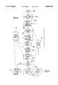
- FIG. 1is a schematic diagram of the control system for automated test facility of the present invention
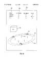
- FIG. 1Ais a schematic representation of a graphic display of the operator interface
- FIG. 2is a perspective view of a test vehicle showing the guidance antennas and guide wire, with portions of the vehicle broken away;
- FIG. 3is a perspective view of a test vehicle showing the position antenna juxtaposed with a position transponder, with portions of the vehicle broken away;
- FIG. 4is a schematic diagram of the vehicle controller (VCON) of the present invention.
- FIG. 5is a schematic diagram of the guide board of the present invention.
- FIG. 6is a flow chart showing the overall control steps of the present invention.
- FIG. 7is a flow chart showing the operational steps of the vehicle controller (VCON);
- FIG. 8is a schematic diagram of a control message
- FIG. 9is a schematic diagram of a report message
- FIG. 10is a flow chart of the off-track routing control
- FIG. 11is a flow chart of the database interface function of the base station.
- FIG. 12is a flow chart of the operator interface operation.
- a control systemfor automatically guiding a plurality of vehicles 12 around a test track 14.
- the system 10 shown in FIG. 1includes a base station 16 and an operator interface 18.
- an operatorcan, via the operator interface 18, input data to the base station 16 that is representative of a desired movement or series of movements of each vehicle 12 around the test track 14.
- the base station 16communicates with vehicle controllers (VCON) 20 that are positioned in the passenger compartments of respective vehicles 12, and the VCON 20 are operably associated with various control apparatus to operate the controls of the associated vehicle 12 to cause the vehicle 12 to move.
- VCONvehicle controllers
- FIG. 1shows that the operator interface 18 is electrically connected to a data display device 22, e.g., a video monitor.
- the data display device 22can include both alpha-numeric and graphical data presentations.
- the display device 22can display a column 22a of alpha-numeric characters representative of the model and test number of each vehicle 12, followed by a column 22b of alpha-numeric characters representative of the percentage completion of the desired test for the vehicle listed in the same row.
- the display device 22can display a column 22c of alpha-numeric characters showing the quantity of fuel remaining, in percent, for each vehicle, followed by a column 22d of alpha-numeric characters showing the status of the associated vehicle 12, e.g., "OK".
- the display device 22can present two-dimensional or three-dimensional images 12a of the vehicles 12, as well as an image 14a of the track 14. Also, the display device 22 can present an image 44a of relay antennas discussed below. Further, the display device 22 can present an image 16a of the base station 16, and images 76a of position transponders discussed further below.
- the operator interface 18is electrically connected to an input device 24, e.g., a keyboard, mouse, touch screen, pen, or voice recognition device.
- an input device 24e.g., a keyboard, mouse, touch screen, pen, or voice recognition device.
- the operator interface 18is a personal computer or laptop computer which recognizes machine readable computer code to execute desired input commands, store and transfer data, etc. in accordance with principles well-known in the art.
- the operations of the operator interface 18, as well as the operations of the base station 16 described below,could be embodied in machine-readable form and stored on a computer program storage device having a data storage medium, such as a computer floppy diskette.
- a data storage mediumsuch as a computer floppy diskette.
- such mediacan also be found in semiconductor devices, on magnetic tape, on optical disks, on a DASD array, on magnetic tape, on a conventional hard disk drive, on electronic read-only memory or on electronic random access memory, or other appropriate data storage device.
- the computer-executable instructionsmay be lines of compiled C or C ++ language code.
- the operator interface 18is electrically connected to a file server/database 26.
- the file server/database 26includes a Cybase database on a Novell server, running on a model 486 computer made by Intel.
- the base station 16includes a global memory 30 for electronically storing data pertaining to the operation of the system 10. As shown, the global memory 30 is electrically connected to the file server/database 26. Also, the base station 16 includes a database interface (db interface) 32 which functions as an interface between the file server/database 26 and base station 16 in accordance with principles discussed below.
- db interfacedatabase interface
- a traffic manager 34 of the base station 16is in communication with the global memory 30 for purposes to be shortly disclosed.
- a plurality of vehicle managers 36are in communication with the global memory 30. It is to be understood that a respective vehicle manager 36 is associated with each vehicle 12 on the track 14. As also shown, the vehicle managers 36 are also in communication with the db interface 32 for receiving and sending information to and from the file server/database 26.
- each vehicle manager 36is electrically connected to a radiofrequency (rf) communications base transceiver 38.
- the transceiver 38is a spread spectrum transceiver. As recognized by the present invention, such a transceiver provides high data bandwidth and relative immunity from multi-path effects.
- the base transceiver 38is an ARLAN transceiver made by Aironet of Canada operating at a frequency in the range of between about eight hundred megaHertz and five gigaHertz (800 mHz-5 gHz) and preferably at a frequency of 2.46 gHz.
- the base transceiver 38is in communication with a wake-up listener module 40 of the base station 16.
- the database interface 32, traffic manager 34, vehicle managers 36, and wake-up listener 40are realized in software, and that the base station 16 accordingly is a computer.
- the base station 16is a type Alpha computer made by Digital Electronics Corp. (DEC).
- the base transceiver 38is electrically connected to a base antenna 42, and as can be appreciated in reference to FIG. 1, the base antenna 42 is in communications with one or more other components of the system 10.
- the transceiver 38 via the base antenna 42communicates, preferably via dual point fiber optic pairs 43, with one or more (preferably five) relay stations 44 that are positioned in sequence around the track 14.
- the relay stations 44are in rf communication with the vehicles 12 via respective vehicle antennae 46 that are mounted on the roofs of their respective vehicles 12.
- each vehicle antenna 46is electrically connected to a respective vehicle transceiver 48 within the associated vehicle 12.
- the vehicle transceivers 48are preferably ARLAN transceivers, with the outputs of each vehicle transceiver 48 being sent to a respective VCON 20.
- each vehicle 12includes a respective guidance antenna, generally designated 50, for sensing one of a plurality of guide wires 52 (only one guide wire 52 shown) that are embedded in the track 14, generally parallel to and spaced from each other. Occasionally, however, the wires intersect for lane change purposes.
- the guidance antenna 50is a dual-coil antenna that generates a guidance signal which is usable by the associated VCON 20 to guide the vehicle 12.
- the guidance antenna 50includes a right inductive coil 54 and a left inductive coil 56.
- the vehicle 12defines a longitudinal centerline 58, and the coils 54, 56 are mounted on the vehicle 12 and are spaced from the centerline 58 of the vehicle 12 equally and oppositely from each other.
- the coils 54, 56are spaced eighteen inches (18") to the right and left, respectively, of the centerline 58 of the vehicle 12.
- the coils 54, 56are positioned roughly twelve inches (12") above the ground.
- each coil 54, 56is affixed to an elongated rigid support brace 60 by respective left and right mounts, e.g., by means of respective ties 62 or bolts (not shown).
- the support brace 60is advantageously mounted on the front of the vehicle 12 as shown, preferably by engaging four bolts 64 with four respective holes 65 that are formed in the brace 60.
- the bolts 64are in turn threadably engaged with the standard four front license plate attaching nuts of the vehicle 12. Thereby, easy mounting of the guidance antenna 50 is facilitated on a wide variety of vehicles 12.
- each guide wire 52is electrically connected to a frequency generator 66 for generating a signal that is characterized by a frequency in the associated guide wire 52.
- the frequency in each guide wire 52is different from the frequencies in the other guide wires. Consequently, the VCON 20 of a vehicle 12 is instructed to follow a predetermined frequency and, hence, to cause the associated vehicle 12 to follow a predetermined course around the test track 14. It is to be understood that with the above-disclosed novel arrangement, the VCON 20 can be programmed to follow a first frequency around a predetermined part of the track 14, and then switch to and follow a second frequency, thereby changing its course to another guide wire 52.
- the frequency generator 66includes a controllable current amplifier characterized by low distortion and low noise, thereby facilitating the establishment of a constant field strength in the guide wire 52 independent of the particular frequency selected.
- the frequency generator 66is a crystal controlled oscillator.
- the electromagnetic field generated by the wire 52 when it is energizedinduces the coils 54, 56 to generate respective guidance error signals.
- the signals from the coils 54, 56are conducted to the associated VCON 20 via electrical leads 66.
- the guidance error signalsare equal and when combined together they establish a balanced signal.
- the coils 54, 56are not spaced equidistantly from the guide wire 52, when the guidance error signals are combined together they produce an unbalanced signal with a polarity consistent with the lateral error from center.
- the VCON 20includes one or more servo controllers 70.
- the servo controller 70generates a position signal representative of the combination of the guidance error signals and sends it to a computer 72.
- the servo controller 70controls the steering wheel of the vehicle 12.
- a position loop antenna 74 having five turns of wireis movably mounted to the vehicle 12 and is configured generally as a rectangle.
- the track location antenna 74senses position identification signals from rf position transponders 76 that are embedded in the track 14 adjacent the guide wire 52 at known fixed locations. Indeed, the system 10 contains a map of the entire track 14 with transponders 76.
- the transponders 76are TIRIS transponders made by Texas Instruments. Per the present invention, several query pulses per second are generated by the VCON 20 and are transmitted from the track location antenna 74. When the track location antenna 74 is adjacent one of the transponders 76 and the track location antenna 74 emits a query pulse, the transponder 76 is energized by the query pulse to emit a position identification signal pulse in response back to the track location antenna 74.
- the position identification signal pulsecontains information that represents the identity of the particular transponder 76 (and, hence, the position of the vehicle 12 on the track 14).
- the position identification signal pulsesare sent via an electrical lead 78 (FIG. 3) to the VCON 20 (FIG. 1) of the vehicle 12.
- the VCON 20determines its position on the track 14 based on the position identification signal pulse, and then transmits a position signal, via the communication system discussed above, to the base station 16 (FIG. 1).
- components of the vehicle 12can interfere with proper reception of position identification signal pulses by the track location antenna 74.
- variations in vehicle fuel tank location, exhaust pipes, etc.exist between the various vehicle models it is desired to test. Consequently, the present invention recognizes that it would be advantageous to provide for easily mounting the track location antenna 74 on the vehicle 12, and for adjusting the height of the antenna 74 as appropriate to ensure satisfactory reception of the position identification signal pulses from the transponders 76.
- FIG. 3shows that the track location antenna 74 is movably mounted on the rear of the vehicle 12 for movement of the antenna 74 in the vertical dimension as appropriate to ensure adequate reception of the position identification signal pulses.
- a stationary frame member 80includes a flat plate 82 that is formed with a plurality of holes 81. The holes 81 are spaced apart so that four respective bolts 84 can be advanced through the holes and into threadable engagement with the four rear license plate frame receptacles of the vehicle 12. Additionally, the stationary frame member 80 includes left and right flanges 86, 88 that are formed integrally with or attached to the plate 82 and extend longitudinally rearwardly therefrom.
- a sliding frame memberis slidably engaged with the stationary frame member 80 for vertical motion of the sliding frame member 90 relative to the vehicle 12.
- the sliding frame member 90includes left and right upper L-beams 92, 94.
- Respective upper support flanges 96, 98extend laterally outwardly from the L-beams 92, 94, and respective plastic support blocks 100, 102 depend downwardly from and are bolted to the upper support flanges 96, 98.
- a top segment 104 of the track location antenna 74is snugly sandwiched between the plastic support blocks 100, 102 and the upper support flanges 96, 98 as shown.
- the sliding member 90includes an elongated, transversely-oriented plastic lower support block 106 that is formed with side channels 108, 110 for respectively supporting side segments 112, 114 of the track location antenna 74.
- Left and right plastic connecting plates 116, 118are bolted to the lower support block 106 as shown.
- left and right elongated, vertically-oriented cylindrical slide bars 120, 122are attached to the connecting plates 116, 118. As shown in FIG. 3, the slide bars 120, 122 are slidably engaged with complementarily-shaped channels in respective bar bearings 124 (only one bearing 124 shown) that are formed integrally with or affixed to the flanges 86, 88 of the stationary frame member 80.
- Respective set screws 126are threadably engaged with the flanges 86, 88, and the set screws 126 can be manipulated to abut the respective slide bars 120, 122. It can now be appreciated that the set screws 126 can be loosened to release the slide bars 120, 122 and permit moving the sliding frame member 90 with track location antenna 74 up and down as appropriate to establish a height of the antenna 74 as appropriate for proper reception of position identification signal pulses from the transponders 76. Then, the set screws 126 can be tightened against the slide bars 120, 122 to stationarily hold the sliding frame member 90 against the stationary frame member 80 and thereby maintain the established height of the track location antenna 74.
- the VCON 20includes a computer or master central processing unit (CPU) 72, preferably a type MVME 162/22 CPU made by Motorola.
- the master CPU 72is electrically connected to a slave CPU 130, and the slave CPU 130 includes the servo controller 70.
- the servo controller 70is a servo controller made by Technology 80.
- the master CPU 72is also connected via a coaxial cable 131 to the vehicle transceiver 48 via a transceiver interface 132.
- the transceiver interface 132translates data from the transceiver 48 into binary code that is recognizable by the master CPU 72.
- the transceiver interface 132translates binary code from the master CPU 72 into data that is intelligible to the transceiver 48.
- the transceiver interface 132translates binary code from the master CPU 72 into a ten base two format for transmission of the data by the vehicle transceiver 48 to the base station 16.
- FIG. 4shows that the slave CPU 130 with servo controller 70 is operationally connected to both the track location antenna 74 and the coils 54, 56 of the guidance antenna 50.
- the coils 54, 56, the left and right coils 56, 54 of the guidance antenna 50are electrically connected to a guide circuit 134, with the guide circuit 134 being connected to the slave CPU 130 with servo controller 70 through an analog-to-digital input-output (ADIO) converter 136.
- ADIOanalog-to-digital input-output
- the slave CPU 70, master CPU 72, and ADIO decoder 136are connected to a parallel bus 137.
- the ADIO converter 136is an analog-to-digital conversion device made by Greenspring for converting the analog signal from the guide circuit 134 to a digital output for use by the slave CPU 130 with servo controller 70.
- the guide circuit 134includes a signal conditioning circuit and a frequency defining circuit. More particularly, the signal conditioning circuit of the guide circuit 134 includes a gain and level amplifier 138. Per the present invention, the guide signals from the coils 54, 56 are combined and then input to the gain and level amplifier 138. In response, the gain and level amplifier 138 amplifies the guide signal from the coils 54, 56 and establishes an output signal having an amplitude within a predetermined range.
- the signalis further amplified by a driver amplifier 140.
- the driver amplifier 140is a type MC34084 operational amplifier (opamp).
- the amplifiers 138, 140establish an output signal of the guide circuit 134 which has, after being processed through the remaining below-described components of the guide circuit 134, an amplitude of plus or minus five volts DC ( ⁇ 5 vDC) when the coils 54, 56 are not equidistantly spaced from the guide wire 52, and an amplitude of minus one volt DC (-1 vDC) when the coils 54, 56 are equidistantly spaced from the guide wire 52.
- ⁇ 5 vDCplus or minus five volts DC
- -1 vDCamplitude of minus one volt DC
- the output of the driver amp 140is sent to a fourth order switched capacitor bandpass filter 142.
- the bandpass filter 142outputs only signals having a predetermined frequency.
- a noise filter 144filters noise from the signal in accordance with well-understood principles, and then the signal is rectified by a rectifier 146 and converted to DC by a root mean square (RMS) converter 148, also in accordance with well-known principles of signal processing.
- RMSroot mean square
- the output signal of the guide circuit 134is sent to the ADIO converter 136 as shown. Also, the output is sent to a frequency detector 150, which detects whether an output voltage is present and, hence, whether a signal having the proper frequency was passed by the bandpass filter 142. The output of the frequency detector 150 is sent to the master CPU 72 as shown, such that the master CPU 72 can determine whether guidance of the vehicle 12 has been lost by virtue of the absence of a guide signal from the guidance circuit 134.
- FIG. 5further shows the means by which the guide frequency is established. It is to be understood that instructions to follow a particular guidance frequency which the vehicle 12 is to "follow” are downloaded (via the rf link described above) from the respective vehicle manager 36 (FIG. 1) of the base station 16 to the VCON 20. In other words, the base station 16 instructs the VCON 20 which guide wire 52 to "follow".
- This guidance signal instructionis transmitted from the master CPU 72 to a logic decoder 152.
- the logic decoder 152converts the binary signal from the master CPU 72 to a guidance frequency command, and then sends the guidance frequency command to a multiplexer (MUX) decoder 154.
- FIG. 5also shows that the MUX decoder 154 receives a plurality of frequency inputs from a clock frequency generator 156. Together, the logic decoder 152, MUX decoder 154, and frequency generator 156 establish a frequency defining circuit.
- each input from the generator 156corresponds to a guide wire 52 frequency. Accordingly, the MUX decoder 154 matches the guidance frequency command with the appropriate input from the generator 156 and outputs a guidance frequency instruction to the bandpass filter 142 to configure the bandpass filter 142 to pass only signals having frequencies substantially equal to the guide frequency.
- the output signal of the track location antenna 74is sent to a position circuit 158.
- the position circuit 158is a TIRIS position circuit by Texas Instruments.
- the position circuit 158periodically (e.g., every few hundred milliseconds) outputs transponder identification information to the slave CPU 130 with servo controller 70 over an RS232 connection 159, which in turn communicates to the master CPU 72.
- the position circuit 158repeatedly generates a query pulse of about fifty milliseconds (50 ms) in duration which is transmitted by the track location antenna 74 toward the track 14. Then, the position circuit 158 is enabled for a predetermined period (e.g., thirty milliseconds) to receive a position identification signal pulse, which is generated by a transponder 76 (FIG. 1) if the transponder 76 is sufficiently close to the track location antenna 74.
- a predetermined periode.g., thirty milliseconds
- the position identification signal pulseis representative of the identity of the transponder 76 and, hence, is representative of the position of the vehicle 12 on the track 14.
- the position identification signal pulseis detected by the position circuit 158 and sent to the slave CPU 130 with servo controller 70 for use by the master CPU 72 as described below.
- FIG. 4shows that the guide circuit 134, position circuit 158, and ADIO converter 136 are connected to a select bus 160. It may now be appreciated that the ADIO converter 136 determines which of the circuits 134, 158 are read by the slave CPU 130. In other words, the ADIO converter 136 manages communications between the antennas 50, 74 and the CPUs of the present invention in accordance with principles well-known in the art to avoid communications interference.
- FIG. 4still further shows that the slave CPU 130 is connected to a connector backplane 162 via "B" and “C” connector ribbons 164, 166. It may now be appreciated that control signals from the slave CPU 130 with servo controller 70 are sent to the backplane 162 for controlling the servos that operate the various controls of the vehicle 12.
- the ADIO converter 136is connected to the connector backplane 162 via a connector ribbon 168.
- the backplane 162isolates the servo amplifiers 170 from the CPUs 130, 72 to limit the introduction of random, unintended commands to the servo amplifiers 170.
- the backplane 162is physically configured as appropriate to provide convenient connections between the various components of the VCON 20.
- the backplane 162includes opto-isolators for isolating servo amplifiers 170 (also preferably made by Copley) that are connected to the backplane 162 from noise signals.
- the backplane 162includes electrical buffers and electrical connector for effecting noise-free connection from the slave CPU 130 with servo controller 70 to the servo amplifiers 170.
- the skilled artisanwill recognize that the servo amplifiers 170 are tuned for the particular vehicle 12.
- the servo amplifiers 170are connected to a steering servo 172, a brake servo 174, an accelerator servo 176, and a shift servo 178.
- the servos 172-178are respectively mechanically coupled to the steering wheel, brake pedal, accelerator pedal, and shifter of the vehicle 12.
- the servos 172-178operate respective encoders 172a-178a and limit switches 172b-178b in accordance with well-known principles. As shown in FIG. 4, the signals from the encoders 172a-178a and limit switches 172b-178b are fed back to the backplane 162 and, hence, to the servo controller 70 for controlling the servo amplifiers 170 in accordance with servo feedback operation.
- the encoders 172a-178aoutput signals respectively representative of the positions of the steering wheel, brake pedal, accelerator pedal, and shifter of the vehicle 12.
- the limit switches 172b-178boutput signals representative of whether the steering wheel, brake pedal, accelerator pedal, and shifter, respectively, have reached predetermined positions.
- FIG. 4shows that the master CPU 72 is connected to a power up device (PUD) 180.
- the PUD 180includes a flight recorder 182 which extracts data from the communications bus 184 of the vehicle 12.
- the communications bus 184is a so-called J1850 bus
- the flight recorder 182is a Motorola 68HC11 microprocessor.
- the data extracted from the bus 184 by the flight recorder 182includes vehicle 12 speed, engine rpm, throttle position, and engine oil pressure low warning signal. This data is sent to the master CPU 72 as shown.
- the flight recorder 182communicates with an input-output expander decoder 186.
- a manual data input device 188such as a keypad, is also connected to the decoder 186.
- the decoder 186receives a vehicle 12 VCON internal temperature signal from one or more temperature sensors 190.
- the decoder 186also receives from other of the sensors 190 signals that represent the temperatures of the shock absorbers of the vehicle 12.
- the temperature sensors 190can be dual-blade thermocouples made by Marlin.
- the decoder 186communicates with a key actuator 192 to operate the actuator 192.
- Details of the key actuator 192are set forth in the first of the above-referenced patent applications.
- a four position select switch 194is also connected to the decoder 186.
- the select switch 194can be manipulated to one of four positions. These positions respectively correspond to “disable”, in which no power is to be supplied to the VCON 20, "power”, in which power is supplied to the VCON 20 but the VCON 20 does not control the vehicle 12, "local”, in which the vehicle 12 can be controlled through the VCON 20 by means of the manual input device 188, and "remote”, in which the VCON 20 controls the vehicle 12 in response to signals downloaded from the base station 16.
- the signals from the select switch 194, manual input device 188, and temperature sensors 190are sent to the master CPU 72 via the PUD 180 for use as described below.
- the VCON 20uses power from various dc-dc voltage converters 196.
- the voltage converters 196collectively generate 36 volt power, 15 volt power, 12 volt power, and 5 volt power.
- the voltage converters 196receive input power from the battery 198 of the vehicle 12 via power relays 200 that are controlled by the PUD 180 as shown.
- FIGS. 1 and 6the overall operation of the system 10 can be appreciated. It is to be understood that while for clarity of disclosure the discussion below focusses on a single vehicle 12, the system 10 undertakes the below steps for all vehicles 12 on the track 14. It is to be further understood that while the processes below are shown in flow chart format, they run continuously during operation of the vehicle 12 on the track 14, as indicated by the feedback loops in the flow charts.
- the systemstarts at circle 202 and proceeds to decision diamond 204, wherein the VCON 20 determines whether the select switch 194 (FIG. 4) is in "remote” and whether the passenger compartment temperature as indicated by the sensors 190 is within the operating temperature limits of the VCON 20. If so, the logic proceeds to block 206, wherein the base station 16 signals the power-up device (PUD) to start the VCON 20 by appropriately operating the key actuator 192 (FIG. 4) as described in the second of the above-referenced patent applications. Also at block 206, the operator defines the desired test program of the vehicle 12 using the operator interface 18, the details of which are disclosed further below in reference to FIG. 12.
- the vehicle 12transmits its identification to the wake-up listener 40.
- the wake-up listener 40creates a vehicle manager 36 at the base station 16 at block 210.
- the base station 16transfers the desired test to the vehicle manager 36, which in turn transfers it to the VCON 20 of the vehicle 12.
- the vehicle 12drives around the track 14. While doing so, at block 214 the VCON 20 reports various data to the base station 16 via the rf network described above. More particularly, at block 214 the VCON 20 periodically (e.g., every three hundred milliseconds (300 ms)) reports shock absorber temperature, whether the low oil pressure switch of the vehicle 12 has been activated, vehicle 12 speed, vehicle 12 position as reported by the position circuit 158 (FIG. 4), and whether the required guide wire 52 frequency has been sensed as reported by the frequency detector 150 of the guide board 134 (FIG. 5).
- shock absorber temperaturee.g., every three hundred milliseconds (300 ms)
- the vehicle manager 36updates the global memory 30 each reporting period.
- the database interface 32updates the database 26 every update period, e.g., every five minutes.
- the database interface 32monitors the database 26 for any new commands or updates entered into the database 26 via the operator interface 18 at block 220.
- the database interface 32determines whether a new entry is present in the database 26, and if so, the process loops back to block 212. Otherwise, the process returns to block 218.
- the base station 16makes several determinations. Specifically, at decision diamond 224, the base station determines whether the reported vehicle 12 shock absorber temperature exceeds a predetermined temperature. If so, the base station 16 proceeds to block 232, wherein the vehicle 12 is stopped and exited from the track 14 using the process described in FIG. 10 below. Also, the database interface 32 updates the database 26, and the updated status is presented on the display 22.
- the processproceeds to decision diamond 234, wherein the base station 16 determines whether the vehicle 12 test has been completed. If so, the base station 16 proceeds to block 236, wherein the vehicle manager 36 routes the vehicle 12 off-track using the process described below in reference to FIG. 10. Otherwise, the system continues to monitor and report as described. Also from diamond 234 if the test there is negative the system continues to monitor and report as described.
- the base station 16determines, at decision diamond 226, whether the speed of the vehicle 12 is an anomaly. More particularly, the vehicles 12 on the track 14 operate at a common speed, e.g., twenty five miles per hour (25 mph) to avoid mutual interference. If a vehicle 12 reports a speed that exceeds or is less than the common speed by a predetermined amount, e.g., five miles per hour, an anomaly is indicated at decision diamond 226. If a speed anomaly exists, the process moves to block 232. Otherwise, the process moves directly to decision diamond 234.
- a common speede.g., twenty five miles per hour (25 mph) to avoid mutual interference.
- the base station 16determines whether the reported position of the vehicle 12 is an anomaly. More particularly, the vehicle 12 periodically reports its position as disclosed previously. Additionally, the vehicle manager 36 determines, based on the last reported position and reported speed, what the next position reported should be. If the reported position is not within a predetermined envelope (e.g., fifty feet) of the expected position, or if no report of a detection of a transponder 76 (FIG. 3) is made when expected, a position anomaly is indicated at decision diamond 228. If a position anomaly exists, the process moves to block 232. Otherwise, the process moves directly to decision diamond 234.
- a predetermined envelopee.g. fifty feet
- the base station 16determines whether any two vehicles are within a predetermined minimum separation distance (e.g., two hundred feet) of each other, both during the current cycle and at a predetermined time period in the future, e.g., thirty seconds. If the distance between any two vehicles is less than the minimum separation distance, an interference anomaly is indicated at decision diamond 230. If an interference anomaly exists, the process moves to block 232. Otherwise, the process moves directly to decision diamond 234.
- a predetermined minimum separation distancee.g., two hundred feet
- the operation of the VCON 20can be appreciated.
- the VCONproceeds to decision diamond 240, wherein the VCON 20 determines whether the select switch 194 (FIG. 4) is in the "remote" or "local” position, indicating that the VCON 20 is enabled to operate the vehicle 12 in response to base station 16 commands or manual input device 188 commands, respectively. As shown in FIG. 7, the VCON 20 does not proceed until the select switch 194 is in one of these operate positions.
- the VCON 20then proceeds to block 242, wherein the VCON 20 receives the desired test instructions via the above-described rf communication path from the associated vehicle manager 36 (FIG. 1) of the base station 16.
- the command from the vehicle manager 36includes a routing sequence from transponder 76 to transponder 76 at predetermined speeds, following predetermined guide wire 52 frequencies.
- the VCON 20then moves to block 244 to establish motion parameters for the vehicle 12. For example, at block 244 the VCON 20 establishes initial positions for the servos 172-178 as appropriate to execute the first routing command received at block 242.
- Steps 246-262illustrate how the VCON 20 causes the vehicle 12 to execute the desired test. Stated differently, the process described below is a preferred example of a vehicle operating parameter error controller.
- the VCON 20determines whether a course error is indicated. If not, the VCON 20 moves to block 248 to transmit a status report to the base station 16 at the appropriate transmission time.
- the VCON 20determines that a course error exists, the VCON 20 moves to block 250 to operate the steering servo 172 (FIG. 4).
- the steering servo 172operates a steering actuator to turn the steering wheel of the vehicle 12 as appropriate to correct the course error, in accordance with well-known servo feedback control principles.
- An example of a steering actuator that can be usedis disclosed in the second of the above-referenced patent applications.
- the VCON 20monitors for speed errors at decision diamond 252. To do this, depending on the desired speed, the VCON 20 monitors one or more of the following inputs from the flight recorder 182 (FIG. 4): speedometer reading (for higher speeds, e.g., in excess of 10 miles per hour), engine speed and engine throttle position (for lower speeds).
- the VCON 20proceeds to decision diamond 254 to ascertain the magnitude and direction of the speed error. If the magnitude and direction of the speed error do not exceed a predetermined error, the VCON 20 proceeds to block 256, wherein the accelerator servo 176 (FIG. 4) is activated to depress or release the accelerator of the vehicle 12 as appropriate to correct the speed error, in accordance with well-known servo feedback control principles.
- the accelerator servo 176FIG. 4
- An example of an accelerator actuator that can be usedis disclosed in the second of the above-referenced patent applications. It is to be understood that the predetermined magnitude and speed error is a predetermined overspeed error that is empirically established as appropriate for the particular model of the vehicle 12. From block 256, the VCON 20 moves to block 248.
- both the accelerator servo 176 and brake servo 174are activated to correct the error in accordance with well-known servo feedback control principles. In other words, when the actual speed exceeds the desired speed by a predetermined amount, the accelerator pedal is released and the brake pedal depressed.
- An example of a brake actuator that can be usedis disclosed in the second of the above-referenced patent applications. From block 258, the VCON 20 moves to block 248.
- the VCON 20determines, at decision diamond 260, whether the gear shift lever of the vehicle 12 is in a position appropriate for the desired speed. If it is not, the VCON 20 proceeds to block 262 to operate the shift servo 178, and thence to block 248. Otherwise, the VCON 20 proceeds directly to block 248 from decision diamond 260.
- An example of a shift lever actuator that can be usedis disclosed in the second of the above-referenced patent applications.
- VCON 20proceeds to decision diamonds 264, 270, 272, 274 to determine whether any failure mode exists in the vehicle 12, and to undertake corrective action if it does. Stated differently, the process described below is a preferred example of a vehicle safety shutdown determiner.
- the VCON 20determines whether any predetermined task of the VCON 20 and/or PUD 180 has stopped or otherwise failed. If not, the VCON 20 moves to block 266 to monitor for new commands from the vehicle manager 36, and then loops back to decision diamonds 246, 252, 254, and 260. Otherwise, the VCON 20 moves to block 268 to stop the vehicle 12 by causing the brake servo 174 to depress the brake pedal and by stopping the engine of the vehicle 12. In accordance with the present invention, the engine can be stopped by issuing an ignition off command to the key actuator 192. From block 268, the VCON 266 moves to block 266 to monitor for a new command in accordance with, e.g., FIG. 10 described below.
- the VCON 20determines, based on the signal from the guide circuit 134, whether the vehicle 12 has become distanced from or otherwise lost detection of the signal in the guide wire 52. If so, the VCON 20 proceeds to block 268, but if not, the VCON 20 proceeds to block 266.
- the VCON 20determines, based on the speedometer signal as sensed by the flight recorder 182, whether the speed of the vehicle 12 exceeds a predetermined speed. If so, the VCON 20 proceeds to block 268, but if not, the VCON 20 proceeds to block 266.
- the VCON 20determines, based on the signal from the vehicle transceiver 48, whether the vehicle 12 has lost communication with the base station 16. If so, the VCON 20 proceeds to block 268, but if not, the VCON 20 proceeds to block 266.
- a command message, generally designated 280, from a vehicle manager 36 of the base station 16 to an associated VCON 20is schematically shown.
- the command message 280includes a header 282 that identifies the particular VCON to which the message 280 is addressed.
- the command message 280includes a body 284.
- FIG. 8illustrates that the body 284 includes a plurality of routing blocks 286, each of which carries data representative of a transponder 76 location, a vehicle speed, and a guide wire 52 frequency. It will readily be appreciated that together the routing blocks 286 establish a desired route and speed for the vehicle 12 around the track 14.
- an auxiliary data block 288can be included to, e.g., command the VCON 20 to transmit status reports at predetermined intervals.
- FIG. 9schematically shows a routine status report message, generally designated 290, and an anomaly status report message, generally designated 296, each of which can be transmitted from a VCON 20 to an associated vehicle manager 36 at the base station 16.
- a header 292identifies the address of the associated vehicle manager 36
- a data block 294includes data pertaining to reporting vehicle 12.
- the data block 294includes the current position of the vehicle 12 as indicated by the output signal of the position circuit 158 (FIG. 4), as well as the percent fuel remaining in the vehicle 12.
- the data block 294includes the current speed of the vehicle 12, shock temperature of the vehicle 12, and whether the oil pressure low switch of the vehicle 12 has been activated.
- the anomaly report message 296includes a header 298 that identifies the address of the associated vehicle manager 36
- the anomaly message 296further includes a data block 300 that indicates the presence of one or more of the above-disclosed vehicle anomalies, along with the current position of the vehicle 12.
- FIG. 10shows that in the event of an anomaly, or in the event that the vehicle 12 has completed its assignment, at block 302 the VCON 20 and/or its associated vehicle manager 36 accesses a map of the track 14 to determine the nearest off-track facility that is appropriate to receive the vehicle 12. For example, if the vehicle 12 has completed its assignment and is low on fuel, the nearest off-track facility that is appropriate to receive the vehicle 12 might be a track gas station located near the track 14. Access roads (not shown) having guide wires embedded therein connect the track 14 with the off-track facilities. Accordingly, in determining the nearest facility, the associated access road is also determined.
- the VCON 20causes the vehicle 12 to reduce speed and follow the frequency of the guide wire that is embedded in the access road selected at block 302.
- FIG. 11shows the details of the data management of the present invention at the base station 16.
- the processmoves to block 322 to set up the global, i.e., shared, memory 30.
- the processmoves to data read block 324, wherein any vehicle commands entered into the database 26 by the operator interface 18 are read and categorized.
- the processmoves to data read block 330, wherein track commands in the database 26 are read. Examples of track commands have been discussed above, e.g., "all vehicles stop” is a track command issued for certain of the above-disclosed anomalies.
- the global (shared) memory 30is updated as appropriate for the read performed at data read block 330.
- the processmoves to data read block 334 to read vehicle data from global (shared) memory 30.
- decision diamond 336it is determined whether any vehicle status change has been reported by one or more of the vehicles 12 to the global memory 30 in accordance with principles discussed above, and if so, the process writes the status change to the database 26 at write block 340. From write block 340, or, if no vehicle status change has been reported at decision diamond 336, the process moves to read block 338, wherein track status changes are read from the global memory 30. Any changes are written to the database 26 at write block 342, and then the process returns to read block 324.
- FIG. 12shows the operator interface processes of the present invention. From start state 350 the process moves to block 352 to set up the working memory. Next, at decision diamond 354, it is determined whether a valid command has been input, and if not, an invalid input is ignored at block 356. Moving from block 356 to decision diamond 358, it is determined whether a keyboard input from the input device 24 (FIG. 1). If so, the process loops back to decision diamond 354, to determine whether the entry was valid.
- the processmoves to block 360, wherein the command is formatted as appropriate.
- the commandis written to the database 26.
- the processmoves to read block 364 to read the track status from the database 26.
- the display 22 (FIG. 1)is updated in response to the read at block 364.
- the processmoves to read block 368 to read the vehicle status from the database 26, and updates the active vehicle screen 22 (FIG. 1) at block 370 in response to the read at block 368.
- the processthen loops back to decision diamond 358.
Landscapes
- Physics & Mathematics (AREA)
- General Physics & Mathematics (AREA)
- Traffic Control Systems (AREA)
Abstract
Description
Claims (8)
Priority Applications (1)
| Application Number | Priority Date | Filing Date | Title |
|---|---|---|---|
| US08/707,118US6061613A (en) | 1996-09-03 | 1996-09-03 | Base station for automated durability road (ADR) facility |
Applications Claiming Priority (1)
| Application Number | Priority Date | Filing Date | Title |
|---|---|---|---|
| US08/707,118US6061613A (en) | 1996-09-03 | 1996-09-03 | Base station for automated durability road (ADR) facility |
Publications (1)
| Publication Number | Publication Date |
|---|---|
| US6061613Atrue US6061613A (en) | 2000-05-09 |
Family
ID=24840422
Family Applications (1)
| Application Number | Title | Priority Date | Filing Date |
|---|---|---|---|
| US08/707,118Expired - LifetimeUS6061613A (en) | 1996-09-03 | 1996-09-03 | Base station for automated durability road (ADR) facility |
Country Status (1)
| Country | Link |
|---|---|
| US (1) | US6061613A (en) |
Cited By (18)
| Publication number | Priority date | Publication date | Assignee | Title |
|---|---|---|---|---|
| US6259991B1 (en)* | 1999-02-10 | 2001-07-10 | X-Cyte Inc. | Environmental location system |
| US6370452B1 (en)* | 1999-12-08 | 2002-04-09 | Samuel T. Pfister | Autonomous vehicle transit system |
| US20020046285A1 (en)* | 2000-09-25 | 2002-04-18 | Pioneer Corporation | Data communication system |
| US6687587B2 (en)* | 2001-12-21 | 2004-02-03 | General Motors Corporation | Method and system for managing vehicle control modules through telematics |
| US6697752B1 (en)* | 2000-05-19 | 2004-02-24 | K&L Technologies, Inc. | System, apparatus and method for testing navigation or guidance equipment |
| US20040181339A1 (en)* | 2003-03-14 | 2004-09-16 | Yoshio Mukaiyama | Vehicular driving support apparatus and driving support method |
| US20040199306A1 (en)* | 2002-12-18 | 2004-10-07 | Harro Heilmann | Method of controlling at least one autonomously driving vehicle |
| US6925380B1 (en)* | 2002-10-30 | 2005-08-02 | Acuere Technologies Corporation | Navigation control system |
| DE102004003099A1 (en)* | 2004-01-21 | 2005-08-18 | TÜV Automotive GmbH | System for driverless implementation of long duration continuous driving tests of motor vehicles has a vehicle control and positioning arrangement with a two-way communications link to a stationary controller |
| US20090125174A1 (en)* | 2007-11-09 | 2009-05-14 | Bruno Delean | Computerized driverless vehicles and traffic control system |
| US20090276589A1 (en)* | 2008-04-30 | 2009-11-05 | Honeywell International Inc. | Method and apparatus for data download from a mobile vehicle |
| US20090287371A1 (en)* | 2007-12-12 | 2009-11-19 | Honeywell International, Inc. | Shock absorber health and condition monitoring device |
| US7628239B1 (en)* | 2006-08-30 | 2009-12-08 | The United States Of America As Represented By The Secretary Of The Navy | Adaptable remote control driving system |
| US20100216498A1 (en)* | 2009-02-24 | 2010-08-26 | Brian Mintah | Fleet communication network |
| US8051936B1 (en)* | 2006-08-30 | 2011-11-08 | The United States Of America As Represented By The Secretary Of The Navy | Human-portable remote control driving system |
| US20170257437A1 (en)* | 2016-03-02 | 2017-09-07 | Tom Freund | Networked Gate Machines Gaging the Condition of Unmanned Platforms |
| US20180266920A1 (en)* | 2017-03-15 | 2018-09-20 | Hyundai Motor Company | Vehicle driving test apparatus and method |
| US20230401908A1 (en)* | 2021-06-09 | 2023-12-14 | Johnny Bohmer Proving Grounds, LLC | System and method for centralized control of vehicle testing |
Citations (109)
| Publication number | Priority date | Publication date | Assignee | Title |
|---|---|---|---|---|
| US1722069A (en)* | 1923-09-22 | 1929-07-23 | Stanley W Widney | Apparatus for charting the riding qualities of vehicles |
| US1950640A (en)* | 1929-12-19 | 1934-03-13 | Bendix Cowdrey Brake Tester In | Foot pedal jack |
| US2716561A (en)* | 1953-03-30 | 1955-08-30 | Ben E Beran | Vehicle safety belt attachment |
| US3001394A (en)* | 1958-05-23 | 1961-09-26 | Walter J Nelson | Road simulating apparatus for vibration testing of motor vehicles |
| FR1376438A (en) | 1963-12-11 | 1964-10-23 | Device for testing the hydraulic braking system of vehicles | |
| US3330477A (en)* | 1964-08-13 | 1967-07-11 | Short Brothers & Harland Ltd | Control systems |
| US3465577A (en)* | 1967-09-28 | 1969-09-09 | Rca Corp | Automobile control manipulating apparatus |
| US3520180A (en)* | 1967-11-08 | 1970-07-14 | Gen Motors Corp | Road simulator facility |
| US3556244A (en)* | 1968-03-15 | 1971-01-19 | Rca Corp | Vehicle road guidance system |
| DE2004979A1 (en) | 1970-02-04 | 1971-08-12 | Porsche Kg | Device for the automatic actuation of the operating devices of vehicles, in particular motor vehicles |
| US3662593A (en)* | 1970-11-23 | 1972-05-16 | Gen Motors Corp | Test apparatus for depressing vehicle brake and accelerator pedals |
| US3696882A (en)* | 1970-02-13 | 1972-10-10 | Kabel Metallwerke Ghh | Method for guiding vehicles automatically along a predetermined path |
| US3877299A (en)* | 1973-07-25 | 1975-04-15 | Clayton Manufacturing Co | Brake pedal actuator |
| US4123023A (en)* | 1977-10-03 | 1978-10-31 | General Motors Corporation | System for controlling vehicle movement over a fixed guideway |
| US4334221A (en)* | 1979-10-22 | 1982-06-08 | Ideal Toy Corporation | Multi-vehicle multi-controller radio remote control system |
| US4361202A (en)* | 1979-06-15 | 1982-11-30 | Michael Minovitch | Automated road transportation system |
| US4379497A (en)* | 1980-09-02 | 1983-04-12 | Bell & Howell, Company | Vehicle collision avoidance system |
| US4442708A (en)* | 1982-09-22 | 1984-04-17 | Ford Motor Company | Automatic driver system |
| US4495801A (en)* | 1981-07-15 | 1985-01-29 | Mitsubishi Denki Kabushiki Kaisha | Manipulator for shifting speed changing gears in automotive vehicles |
| US4499784A (en)* | 1981-11-20 | 1985-02-19 | Westinghouse Electric Corp. | Split-ball type wrist and manipulating assembly for robot |
| US4530056A (en)* | 1982-10-28 | 1985-07-16 | Modular Automation Corp. | Automated guided vehicle system |
| US4554824A (en)* | 1984-12-17 | 1985-11-26 | Ford Motor Company | Automated manual transmission shifter with electronic control actuators external of the vehicle |
| US4556940A (en)* | 1980-09-05 | 1985-12-03 | Mitsubishi Denki Kabushiki Kaisha | Robot vehicle |
| US4585273A (en)* | 1982-09-02 | 1986-04-29 | Hawtal Whiting Design & Engineering Co., Ltd. of Pembroke House | Vehicle seat |
| US4602334A (en)* | 1983-10-31 | 1986-07-22 | Leonard Salesky | Vehicle travel control device |
| US4616326A (en)* | 1982-11-30 | 1986-10-07 | Siemens Aktiengesellschaft | Self optimizing robot controller |
| US4621525A (en)* | 1984-12-17 | 1986-11-11 | Ford Motor Company | Accelerator pedal actuator system for automatic driving system |
| US4647784A (en)* | 1983-05-14 | 1987-03-03 | The General Electric Company Plc | Vehicle guidance and control system |
| US4649742A (en)* | 1984-10-27 | 1987-03-17 | Bayerische Motoren Werke Aktiengesellschaft | Automatic gear-shifting arrangement |
| US4700301A (en)* | 1983-11-02 | 1987-10-13 | Dyke Howard L | Method of automatically steering agricultural type vehicles |
| US4742720A (en)* | 1986-03-04 | 1988-05-10 | Carl Schenck Ag | Reference platform for motor vehicle operation |
| US4777601A (en)* | 1985-03-15 | 1988-10-11 | Jd-Technologie Ag | Method and apparatus for a passive track system for guiding and controlling robotic transport and assembly or installation devices |
| US4780817A (en)* | 1986-09-19 | 1988-10-25 | Ndc Technologies, Inc. | Method and apparatus for providing destination and vehicle function information to an automatic guided vehicle |
| US4790177A (en)* | 1987-10-09 | 1988-12-13 | Ford Motor Company | Shifting control for automated manual transmission shifter |
| US4791570A (en)* | 1985-05-02 | 1988-12-13 | Eaton-Kenway, Inc. | Guide wire communication system and method |
| US4799915A (en)* | 1987-12-04 | 1989-01-24 | Lehmann Roger W | Radio-controlled robot operator for battery-powered toys |
| US4804937A (en)* | 1987-05-26 | 1989-02-14 | Motorola, Inc. | Vehicle monitoring arrangement and system |
| US4813751A (en)* | 1988-04-04 | 1989-03-21 | Fenn Melvin C | Seat mounted utility console |
| US4817040A (en)* | 1986-03-20 | 1989-03-28 | Lucas Industries Public Limited Company | Vehicle condition monitoring system |
| US4822104A (en)* | 1988-02-16 | 1989-04-18 | General Motors Corporation | Seat belt buckle for child restraint |
| EP0236518B1 (en) | 1986-03-08 | 1989-05-17 | Carl Schenck Ag | Apparatus and process for the automatic operation of operating devices of motor vehicles |
| US4855656A (en)* | 1986-08-13 | 1989-08-08 | Murata Kikai Kabushiki Kaisha | Driverless car travelling guide system |
| US4855822A (en)* | 1988-01-26 | 1989-08-08 | Honeywell, Inc. | Human engineered remote driving system |
| US4860209A (en)* | 1983-11-24 | 1989-08-22 | Kabushiki Kaisha Toyota Chuo Kenkyusho | Running command system for unmanned vehicle |
| US4913490A (en)* | 1987-10-26 | 1990-04-03 | Combi Co., Ltd. | Auxiliary chair mounted in vehicle |
| US4939651A (en)* | 1986-12-16 | 1990-07-03 | Shinko Electric Co., Ltd. | Control method for an unmanned vehicle (robot car) |
| US4946120A (en)* | 1988-08-09 | 1990-08-07 | Posting Equipment Corporation | Support |
| US4954761A (en)* | 1987-10-23 | 1990-09-04 | Mitsubishi Jukogyo K. K. | Control system of an industrial robot |
| US4956777A (en)* | 1988-06-09 | 1990-09-11 | R. J. Reynolds Tobacco Company | Automatic vehicle control system |
| US4973083A (en)* | 1989-12-12 | 1990-11-27 | Richards Lawrence O | Seatbelts having immovable anchor straps |
| US5012689A (en)* | 1989-10-04 | 1991-05-07 | Smith Steven R | Vehicle foot pedal actuator apparatus and method |
| US5023790A (en)* | 1989-02-17 | 1991-06-11 | Whs Robotics | Automatic guided vehicle system |
| US5029294A (en)* | 1988-06-17 | 1991-07-02 | Samsung Electronics Co., Ltd. | Sensor unit for traffic control of an automatic guided vehicle |
| US5032994A (en)* | 1989-12-06 | 1991-07-16 | Crown Equipment Corporation | Manual sensing of wire guidance signal |
| US5036935A (en)* | 1989-03-08 | 1991-08-06 | Kabushiki Kaisha Toyoda Jidoshokki Seisakusho | Travel control device for unmanned vehicle |
| US5068790A (en)* | 1989-12-06 | 1991-11-26 | Crown Equipment Corporation | Wire guidance control system |
| US5068791A (en)* | 1989-12-06 | 1991-11-26 | Crown Equipment Corporation | Distance and angle measurements in a wire guided vehicle |
| US5075853A (en)* | 1989-02-17 | 1991-12-24 | Whs Robotics, Inc. | Replaceable vehicle control prom |
| US5111401A (en)* | 1990-05-19 | 1992-05-05 | The United States Of America As Represented By The Secretary Of The Navy | Navigational control system for an autonomous vehicle |
| US5126941A (en)* | 1982-11-08 | 1992-06-30 | Hailemichael Gurmu | Vehicle guidance system |
| US5128599A (en)* | 1989-09-25 | 1992-07-07 | Mannesmann Rexroth Gmbh | Automatic control system |
| US5131682A (en)* | 1990-12-10 | 1992-07-21 | Reed Rosemary J | Seat belt apparatus for sleepers |
| US5163001A (en)* | 1989-02-17 | 1992-11-10 | Luke Jr Walter | Interactive display for use on an automatic guided vehicle |
| US5170351A (en)* | 1990-09-18 | 1992-12-08 | Matushita Electric Industrial Co., Ltd. | Automatic guided vehicle and method for controlling travel thereof |
| US5172589A (en)* | 1989-12-08 | 1992-12-22 | Georg Witt | Robot driver |
| US5175480A (en)* | 1990-01-18 | 1992-12-29 | Mckeefery James | Vehicle guidance and control systems and methods for controllably guiding a vehicle along a predetermined pathway |
| US5179329A (en)* | 1989-04-25 | 1993-01-12 | Shinko Electric Co., Ltd. | Travel control method, travel control device, and mobile robot for mobile robot systems |
| US5184694A (en)* | 1991-05-08 | 1993-02-09 | Pacer Manufacturing Co., Inc. | Remote control system for go kart track and go kart conversion kit |
| US5189612A (en)* | 1987-02-04 | 1993-02-23 | Protee Groupement D'interet Economique | System and method of navigating the travel of an autonomous vehicle |
| US5193062A (en)* | 1990-02-07 | 1993-03-09 | Nissan Motor Co., Ltd. | Automatic vehicle driving system and method of driving the same on chassis dynamometer |
| DE3744631C2 (en) | 1987-12-31 | 1993-03-11 | Friedrich Prof. Dr.-Ing. 6600 Saarbruecken De Klinger | |
| US5197346A (en)* | 1991-02-15 | 1993-03-30 | Comau S.P.A. | Articulated robot with two forearms |
| US5220497A (en)* | 1987-11-20 | 1993-06-15 | North American Philips Corp. | Method and apparatus for controlling high speed vehicles |
| US5248187A (en)* | 1991-10-04 | 1993-09-28 | Harrison Rick G | Seat belt extension apparatus |
| US5271092A (en)* | 1990-08-06 | 1993-12-14 | Siemens Aktiengesellschaft | Method for transmitting a permission signal for the operation of a robot |
| US5270628A (en)* | 1990-12-30 | 1993-12-14 | Horiba, Ltd. | Method and apparatus for automatic robotic control of a vehicle |
| US5280431A (en)* | 1985-08-30 | 1994-01-18 | Texas Instruments Incorporated | Method for controlling the movements of a mobile robot in a multiple node factory |
| US5283739A (en)* | 1985-08-30 | 1994-02-01 | Texas Instruments Incorporated | Static collision avoidance method for multiple automatically guided vehicles |
| US5289183A (en)* | 1992-06-19 | 1994-02-22 | At/Comm Incorporated | Traffic monitoring and management method and apparatus |
| US5295551A (en)* | 1986-03-06 | 1994-03-22 | Josef Sukonick | System for the cooperative driving of two or more vehicles |
| US5299130A (en)* | 1989-05-01 | 1994-03-29 | Toyoichi Ono | Apparatus for controlling movement of vehicle |
| US5303154A (en)* | 1991-10-25 | 1994-04-12 | Luke Jr Walter | Continuous on-line communications system for automatic guided vehicles |
| US5303163A (en)* | 1992-08-20 | 1994-04-12 | Cummins Electronics Company | Configurable vehicle monitoring system |
| US5318143A (en)* | 1992-06-22 | 1994-06-07 | The Texas A & M University System | Method and apparatus for lane sensing for automatic vehicle steering |
| US5341130A (en)* | 1990-12-03 | 1994-08-23 | Eaton-Kenway, Inc. | Downward compatible AGV system and methods |
| US5357824A (en)* | 1989-12-28 | 1994-10-25 | Kawasaki Jukogyo Kabushiki Kaisha | Industrial robot |
| US5363027A (en)* | 1991-01-16 | 1994-11-08 | Horiba, Ltd. | Apparatus and method of controlling the robotic driving of a vehicle |
| US5369581A (en)* | 1989-03-17 | 1994-11-29 | Hitachi, Ltd. | Vehicle control apparatus and method therefor |
| US5369591A (en)* | 1993-03-11 | 1994-11-29 | Broxmeyer; Charles | Vehicle longitudinal control and collision avoidance system for an automated highway system |
| US5372035A (en)* | 1991-12-07 | 1994-12-13 | Horiba, Ltd. | Robot for driving an automobile on a chassis dynamometer |
| US5379469A (en)* | 1993-09-27 | 1995-01-10 | Millis; Sandra S. | Infant crib |
| US5379664A (en)* | 1992-10-07 | 1995-01-10 | United Kingdom Atomic Energy Authority | Hydraulic manipulator |
| US5387853A (en)* | 1987-09-30 | 1995-02-07 | Ono; Toyoichi | Automatic travelling system of construction vehicle |
| US5394743A (en)* | 1992-05-09 | 1995-03-07 | Horiba, Ltd. | Method and apparatus for controlling a robot to simulate driving of a motorcar |
| US5396792A (en)* | 1992-05-09 | 1995-03-14 | Horiba, Ltd. | Apparatus and method of controlling a robot to automatically simulate driving of a motorcar |
| US5402051A (en)* | 1992-03-24 | 1995-03-28 | Sanyo Electric Co., Ltd. | Floor cleaning robot and method of controlling same |
| US5415034A (en)* | 1991-09-10 | 1995-05-16 | Horiba, Ltd. | Robot for driving automobile on chassis dynamometer |
| US5416394A (en)* | 1992-09-25 | 1995-05-16 | Samsung Electronics Co., Ltd. | Motor control method and apparatus thereof in numerical control systems |
| US5420794A (en)* | 1993-06-30 | 1995-05-30 | James; Robert D. | Automated highway system for controlling the operating parameters of a vehicle |
| US5430645A (en)* | 1993-09-07 | 1995-07-04 | Keller; A. Scott | Robotic system for testing of electric vehicles |
| US5434781A (en)* | 1993-08-13 | 1995-07-18 | Control Engineering Company | Method and apparatus for guiding a driverless vehicle using a sensor tracking a cable emitting an electromagnetic field |
| USH1469H (en)* | 1992-09-03 | 1995-08-01 | The United States Of America As Represented By The Secretary Of The Navy | Remotely piloted vehicle control and interface system |
| US5442553A (en)* | 1992-11-16 | 1995-08-15 | Motorola | Wireless motor vehicle diagnostic and software upgrade system |
| US5446356A (en) | 1993-09-09 | 1995-08-29 | Samsung Electronics Co., Ltd. | Mobile robot |
| US5448479A (en) | 1994-09-01 | 1995-09-05 | Caterpillar Inc. | Remote control system and method for an autonomous vehicle |
| US5450321A (en) | 1991-08-12 | 1995-09-12 | Crane; Harold E. | Interactive dynamic realtime management system for powered vehicles |
| US5468046A (en) | 1994-07-13 | 1995-11-21 | Hoover Universal, Inc. | Seat belt mounting for integral child seat |
| US5469356A (en) | 1994-09-01 | 1995-11-21 | Caterpillar Inc. | System for controlling a vehicle to selectively allow operation in either an autonomous mode or a manual mode |
| US5485892A (en) | 1991-10-14 | 1996-01-23 | Mazda Motor Corporation | Drive control system for automobile |
- 1996
- 1996-09-03USUS08/707,118patent/US6061613A/ennot_activeExpired - Lifetime
Patent Citations (111)
| Publication number | Priority date | Publication date | Assignee | Title |
|---|---|---|---|---|
| US1722069A (en)* | 1923-09-22 | 1929-07-23 | Stanley W Widney | Apparatus for charting the riding qualities of vehicles |
| US1950640A (en)* | 1929-12-19 | 1934-03-13 | Bendix Cowdrey Brake Tester In | Foot pedal jack |
| US2716561A (en)* | 1953-03-30 | 1955-08-30 | Ben E Beran | Vehicle safety belt attachment |
| US3001394A (en)* | 1958-05-23 | 1961-09-26 | Walter J Nelson | Road simulating apparatus for vibration testing of motor vehicles |
| FR1376438A (en) | 1963-12-11 | 1964-10-23 | Device for testing the hydraulic braking system of vehicles | |
| US3330477A (en)* | 1964-08-13 | 1967-07-11 | Short Brothers & Harland Ltd | Control systems |
| US3465577A (en)* | 1967-09-28 | 1969-09-09 | Rca Corp | Automobile control manipulating apparatus |
| US3520180A (en)* | 1967-11-08 | 1970-07-14 | Gen Motors Corp | Road simulator facility |
| US3556244A (en)* | 1968-03-15 | 1971-01-19 | Rca Corp | Vehicle road guidance system |
| DE2004979A1 (en) | 1970-02-04 | 1971-08-12 | Porsche Kg | Device for the automatic actuation of the operating devices of vehicles, in particular motor vehicles |
| US3713332A (en)* | 1970-02-04 | 1973-01-30 | Porsche Kg | Apparatus for the automatic operation of operating devices for motor vehicles |
| US3696882A (en)* | 1970-02-13 | 1972-10-10 | Kabel Metallwerke Ghh | Method for guiding vehicles automatically along a predetermined path |
| US3662593A (en)* | 1970-11-23 | 1972-05-16 | Gen Motors Corp | Test apparatus for depressing vehicle brake and accelerator pedals |
| US3877299A (en)* | 1973-07-25 | 1975-04-15 | Clayton Manufacturing Co | Brake pedal actuator |
| US4123023A (en)* | 1977-10-03 | 1978-10-31 | General Motors Corporation | System for controlling vehicle movement over a fixed guideway |
| US4361202A (en)* | 1979-06-15 | 1982-11-30 | Michael Minovitch | Automated road transportation system |
| US4334221A (en)* | 1979-10-22 | 1982-06-08 | Ideal Toy Corporation | Multi-vehicle multi-controller radio remote control system |
| US4379497A (en)* | 1980-09-02 | 1983-04-12 | Bell & Howell, Company | Vehicle collision avoidance system |
| US4556940A (en)* | 1980-09-05 | 1985-12-03 | Mitsubishi Denki Kabushiki Kaisha | Robot vehicle |
| US4495801A (en)* | 1981-07-15 | 1985-01-29 | Mitsubishi Denki Kabushiki Kaisha | Manipulator for shifting speed changing gears in automotive vehicles |
| US4499784A (en)* | 1981-11-20 | 1985-02-19 | Westinghouse Electric Corp. | Split-ball type wrist and manipulating assembly for robot |
| US4585273A (en)* | 1982-09-02 | 1986-04-29 | Hawtal Whiting Design & Engineering Co., Ltd. of Pembroke House | Vehicle seat |
| US4442708A (en)* | 1982-09-22 | 1984-04-17 | Ford Motor Company | Automatic driver system |
| US4530056A (en)* | 1982-10-28 | 1985-07-16 | Modular Automation Corp. | Automated guided vehicle system |
| US5126941A (en)* | 1982-11-08 | 1992-06-30 | Hailemichael Gurmu | Vehicle guidance system |
| US4616326A (en)* | 1982-11-30 | 1986-10-07 | Siemens Aktiengesellschaft | Self optimizing robot controller |
| US4647784A (en)* | 1983-05-14 | 1987-03-03 | The General Electric Company Plc | Vehicle guidance and control system |
| US4602334A (en)* | 1983-10-31 | 1986-07-22 | Leonard Salesky | Vehicle travel control device |
| US4700301A (en)* | 1983-11-02 | 1987-10-13 | Dyke Howard L | Method of automatically steering agricultural type vehicles |
| US4860209A (en)* | 1983-11-24 | 1989-08-22 | Kabushiki Kaisha Toyota Chuo Kenkyusho | Running command system for unmanned vehicle |
| US4649742A (en)* | 1984-10-27 | 1987-03-17 | Bayerische Motoren Werke Aktiengesellschaft | Automatic gear-shifting arrangement |
| US4554824A (en)* | 1984-12-17 | 1985-11-26 | Ford Motor Company | Automated manual transmission shifter with electronic control actuators external of the vehicle |
| US4621525A (en)* | 1984-12-17 | 1986-11-11 | Ford Motor Company | Accelerator pedal actuator system for automatic driving system |
| US4777601A (en)* | 1985-03-15 | 1988-10-11 | Jd-Technologie Ag | Method and apparatus for a passive track system for guiding and controlling robotic transport and assembly or installation devices |
| US4791570A (en)* | 1985-05-02 | 1988-12-13 | Eaton-Kenway, Inc. | Guide wire communication system and method |
| US5280431A (en)* | 1985-08-30 | 1994-01-18 | Texas Instruments Incorporated | Method for controlling the movements of a mobile robot in a multiple node factory |
| US5283739A (en)* | 1985-08-30 | 1994-02-01 | Texas Instruments Incorporated | Static collision avoidance method for multiple automatically guided vehicles |
| EP0235333B1 (en) | 1986-03-04 | 1989-05-03 | Carl Schenck Ag | Reference platform for an arrestable alignment |
| US4742720A (en)* | 1986-03-04 | 1988-05-10 | Carl Schenck Ag | Reference platform for motor vehicle operation |
| US5295551A (en)* | 1986-03-06 | 1994-03-22 | Josef Sukonick | System for the cooperative driving of two or more vehicles |
| EP0236518B1 (en) | 1986-03-08 | 1989-05-17 | Carl Schenck Ag | Apparatus and process for the automatic operation of operating devices of motor vehicles |
| US4817040A (en)* | 1986-03-20 | 1989-03-28 | Lucas Industries Public Limited Company | Vehicle condition monitoring system |
| US4855656A (en)* | 1986-08-13 | 1989-08-08 | Murata Kikai Kabushiki Kaisha | Driverless car travelling guide system |
| US4780817A (en)* | 1986-09-19 | 1988-10-25 | Ndc Technologies, Inc. | Method and apparatus for providing destination and vehicle function information to an automatic guided vehicle |
| US4939651A (en)* | 1986-12-16 | 1990-07-03 | Shinko Electric Co., Ltd. | Control method for an unmanned vehicle (robot car) |
| US5189612A (en)* | 1987-02-04 | 1993-02-23 | Protee Groupement D'interet Economique | System and method of navigating the travel of an autonomous vehicle |
| US4804937A (en)* | 1987-05-26 | 1989-02-14 | Motorola, Inc. | Vehicle monitoring arrangement and system |
| US5387853A (en)* | 1987-09-30 | 1995-02-07 | Ono; Toyoichi | Automatic travelling system of construction vehicle |
| US4790177A (en)* | 1987-10-09 | 1988-12-13 | Ford Motor Company | Shifting control for automated manual transmission shifter |
| US4954761A (en)* | 1987-10-23 | 1990-09-04 | Mitsubishi Jukogyo K. K. | Control system of an industrial robot |
| US4913490A (en)* | 1987-10-26 | 1990-04-03 | Combi Co., Ltd. | Auxiliary chair mounted in vehicle |
| US5220497A (en)* | 1987-11-20 | 1993-06-15 | North American Philips Corp. | Method and apparatus for controlling high speed vehicles |
| US4799915A (en)* | 1987-12-04 | 1989-01-24 | Lehmann Roger W | Radio-controlled robot operator for battery-powered toys |
| DE3744631C2 (en) | 1987-12-31 | 1993-03-11 | Friedrich Prof. Dr.-Ing. 6600 Saarbruecken De Klinger | |
| US4855822A (en)* | 1988-01-26 | 1989-08-08 | Honeywell, Inc. | Human engineered remote driving system |
| US4822104A (en)* | 1988-02-16 | 1989-04-18 | General Motors Corporation | Seat belt buckle for child restraint |
| US4813751A (en)* | 1988-04-04 | 1989-03-21 | Fenn Melvin C | Seat mounted utility console |
| US4956777A (en)* | 1988-06-09 | 1990-09-11 | R. J. Reynolds Tobacco Company | Automatic vehicle control system |
| US5029294A (en)* | 1988-06-17 | 1991-07-02 | Samsung Electronics Co., Ltd. | Sensor unit for traffic control of an automatic guided vehicle |
| US4946120A (en)* | 1988-08-09 | 1990-08-07 | Posting Equipment Corporation | Support |
| US5023790A (en)* | 1989-02-17 | 1991-06-11 | Whs Robotics | Automatic guided vehicle system |
| US5163001A (en)* | 1989-02-17 | 1992-11-10 | Luke Jr Walter | Interactive display for use on an automatic guided vehicle |
| US5075853A (en)* | 1989-02-17 | 1991-12-24 | Whs Robotics, Inc. | Replaceable vehicle control prom |
| US5036935A (en)* | 1989-03-08 | 1991-08-06 | Kabushiki Kaisha Toyoda Jidoshokki Seisakusho | Travel control device for unmanned vehicle |
| US5369581A (en)* | 1989-03-17 | 1994-11-29 | Hitachi, Ltd. | Vehicle control apparatus and method therefor |
| US5179329A (en)* | 1989-04-25 | 1993-01-12 | Shinko Electric Co., Ltd. | Travel control method, travel control device, and mobile robot for mobile robot systems |
| US5299130A (en)* | 1989-05-01 | 1994-03-29 | Toyoichi Ono | Apparatus for controlling movement of vehicle |
| US5128599A (en)* | 1989-09-25 | 1992-07-07 | Mannesmann Rexroth Gmbh | Automatic control system |
| US5012689A (en)* | 1989-10-04 | 1991-05-07 | Smith Steven R | Vehicle foot pedal actuator apparatus and method |
| US5032994A (en)* | 1989-12-06 | 1991-07-16 | Crown Equipment Corporation | Manual sensing of wire guidance signal |
| US5068791A (en)* | 1989-12-06 | 1991-11-26 | Crown Equipment Corporation | Distance and angle measurements in a wire guided vehicle |
| US5068790A (en)* | 1989-12-06 | 1991-11-26 | Crown Equipment Corporation | Wire guidance control system |
| US5172589A (en)* | 1989-12-08 | 1992-12-22 | Georg Witt | Robot driver |
| US4973083A (en)* | 1989-12-12 | 1990-11-27 | Richards Lawrence O | Seatbelts having immovable anchor straps |
| US5357824A (en)* | 1989-12-28 | 1994-10-25 | Kawasaki Jukogyo Kabushiki Kaisha | Industrial robot |
| US5175480A (en)* | 1990-01-18 | 1992-12-29 | Mckeefery James | Vehicle guidance and control systems and methods for controllably guiding a vehicle along a predetermined pathway |
| US5193062A (en)* | 1990-02-07 | 1993-03-09 | Nissan Motor Co., Ltd. | Automatic vehicle driving system and method of driving the same on chassis dynamometer |
| US5111401A (en)* | 1990-05-19 | 1992-05-05 | The United States Of America As Represented By The Secretary Of The Navy | Navigational control system for an autonomous vehicle |
| US5271092A (en)* | 1990-08-06 | 1993-12-14 | Siemens Aktiengesellschaft | Method for transmitting a permission signal for the operation of a robot |
| US5170351A (en)* | 1990-09-18 | 1992-12-08 | Matushita Electric Industrial Co., Ltd. | Automatic guided vehicle and method for controlling travel thereof |
| US5341130A (en)* | 1990-12-03 | 1994-08-23 | Eaton-Kenway, Inc. | Downward compatible AGV system and methods |
| US5131682A (en)* | 1990-12-10 | 1992-07-21 | Reed Rosemary J | Seat belt apparatus for sleepers |
| US5270628A (en)* | 1990-12-30 | 1993-12-14 | Horiba, Ltd. | Method and apparatus for automatic robotic control of a vehicle |
| US5363027A (en)* | 1991-01-16 | 1994-11-08 | Horiba, Ltd. | Apparatus and method of controlling the robotic driving of a vehicle |
| US5197346A (en)* | 1991-02-15 | 1993-03-30 | Comau S.P.A. | Articulated robot with two forearms |
| US5184694A (en)* | 1991-05-08 | 1993-02-09 | Pacer Manufacturing Co., Inc. | Remote control system for go kart track and go kart conversion kit |
| US5450321A (en) | 1991-08-12 | 1995-09-12 | Crane; Harold E. | Interactive dynamic realtime management system for powered vehicles |
| US5415034A (en)* | 1991-09-10 | 1995-05-16 | Horiba, Ltd. | Robot for driving automobile on chassis dynamometer |
| US5248187A (en)* | 1991-10-04 | 1993-09-28 | Harrison Rick G | Seat belt extension apparatus |
| US5485892A (en) | 1991-10-14 | 1996-01-23 | Mazda Motor Corporation | Drive control system for automobile |
| US5303154A (en)* | 1991-10-25 | 1994-04-12 | Luke Jr Walter | Continuous on-line communications system for automatic guided vehicles |
| US5372035A (en)* | 1991-12-07 | 1994-12-13 | Horiba, Ltd. | Robot for driving an automobile on a chassis dynamometer |
| US5402051A (en)* | 1992-03-24 | 1995-03-28 | Sanyo Electric Co., Ltd. | Floor cleaning robot and method of controlling same |
| US5394743A (en)* | 1992-05-09 | 1995-03-07 | Horiba, Ltd. | Method and apparatus for controlling a robot to simulate driving of a motorcar |
| US5396792A (en)* | 1992-05-09 | 1995-03-14 | Horiba, Ltd. | Apparatus and method of controlling a robot to automatically simulate driving of a motorcar |
| US5289183A (en)* | 1992-06-19 | 1994-02-22 | At/Comm Incorporated | Traffic monitoring and management method and apparatus |
| US5318143A (en)* | 1992-06-22 | 1994-06-07 | The Texas A & M University System | Method and apparatus for lane sensing for automatic vehicle steering |
| US5303163A (en)* | 1992-08-20 | 1994-04-12 | Cummins Electronics Company | Configurable vehicle monitoring system |
| USH1469H (en)* | 1992-09-03 | 1995-08-01 | The United States Of America As Represented By The Secretary Of The Navy | Remotely piloted vehicle control and interface system |
| US5416394A (en)* | 1992-09-25 | 1995-05-16 | Samsung Electronics Co., Ltd. | Motor control method and apparatus thereof in numerical control systems |
| US5379664A (en)* | 1992-10-07 | 1995-01-10 | United Kingdom Atomic Energy Authority | Hydraulic manipulator |
| US5442553A (en)* | 1992-11-16 | 1995-08-15 | Motorola | Wireless motor vehicle diagnostic and software upgrade system |
| US5369591A (en)* | 1993-03-11 | 1994-11-29 | Broxmeyer; Charles | Vehicle longitudinal control and collision avoidance system for an automated highway system |
| US5420794A (en)* | 1993-06-30 | 1995-05-30 | James; Robert D. | Automated highway system for controlling the operating parameters of a vehicle |
| US5434781A (en)* | 1993-08-13 | 1995-07-18 | Control Engineering Company | Method and apparatus for guiding a driverless vehicle using a sensor tracking a cable emitting an electromagnetic field |
| US5430645A (en)* | 1993-09-07 | 1995-07-04 | Keller; A. Scott | Robotic system for testing of electric vehicles |
| US5446356A (en) | 1993-09-09 | 1995-08-29 | Samsung Electronics Co., Ltd. | Mobile robot |
| US5379469A (en)* | 1993-09-27 | 1995-01-10 | Millis; Sandra S. | Infant crib |
| US5468046A (en) | 1994-07-13 | 1995-11-21 | Hoover Universal, Inc. | Seat belt mounting for integral child seat |
| US5448479A (en) | 1994-09-01 | 1995-09-05 | Caterpillar Inc. | Remote control system and method for an autonomous vehicle |
| US5469356A (en) | 1994-09-01 | 1995-11-21 | Caterpillar Inc. | System for controlling a vehicle to selectively allow operation in either an autonomous mode or a manual mode |
Non-Patent Citations (12)
| Title |
|---|
| E. W. Morris "Developments in Guided Vehicle Systems--Possibilities and LImitations and the Economics of their Operation," MFS (Conferences) Ltd. 1st International Conference on Automated Guided Vehicle Systems, Jun. 2-4, 1981, pp. 67-76. |
| E. W. Morris Developments in Guided Vehicle Systems Possibilities and LImitations and the Economics of their Operation, MFS (Conferences) Ltd. 1st International Conference on Automated Guided Vehicle Systems, Jun. 2 4, 1981, pp. 67 76.* |
| F. Gentil and G. Prodo "Guided Vehicle Systems at Renault," MFS (Conferences) Ltd. 1st International Conference on Automated Guided Vehicle Systems, Jun. 2-4, 1981, pp. 59-65. |
| F. Gentil and G. Prodo Guided Vehicle Systems at Renault, MFS (Conferences) Ltd. 1st International Conference on Automated Guided Vehicle Systems, Jun. 2 4, 1981, pp. 59 65.* |
| Joe Quinlan "The Great AGVS Race," Material Handling Engineering, vol. 35, Mo. 6, pp. 56-64 (Jun. 1980). |
| Joe Quinlan The Great AGVS Race, Material Handling Engineering, vol. 35, Mo. 6, pp. 56 64 (Jun. 1980).* |
| Juerg Sommer "Digitron's Automated Guided Vehicle Systems are Controlled by Standard Software: A Field-Proven Approach," MFS (Conferences) Ltd. 1st International Conference on Automated Guided Vehicle Systems, Jun. 2-4, 1981, pp. 95-101. |
| Juerg Sommer Digitron s Automated Guided Vehicle Systems are Controlled by Standard Software: A Field Proven Approach, MFS (Conferences) Ltd. 1st International Conference on Automated Guided Vehicle Systems, Jun. 2 4, 1981, pp. 95 101.* |
| Jurgen Raschke and Bodo Titze "Automatic Driver for Exhaust Emission and Consumption Measurements," Automobiltechnische Zeitschrift 88 (1986) 7/8. |
| Jurgen Raschke and Bodo Titze Automatic Driver for Exhaust Emission and Consumption Measurements, Automobiltechnische Zeitschrift 88 (1986) 7/8.* |
| L. Marce, M. Julliere and H. Place "An Autonomous Computer-Controlled Vehicle," MFS (Conferences) Ltd. 1st International Conference on Automated Guided Vehicle Systems, Jun. 2-4, 1981, pp. 113-122. |
| L. Marce, M. Julliere and H. Place An Autonomous Computer Controlled Vehicle, MFS (Conferences) Ltd. 1st International Conference on Automated Guided Vehicle Systems, Jun. 2 4, 1981, pp. 113 122.* |
Cited By (29)
| Publication number | Priority date | Publication date | Assignee | Title |
|---|---|---|---|---|
| US6259991B1 (en)* | 1999-02-10 | 2001-07-10 | X-Cyte Inc. | Environmental location system |
| US6370452B1 (en)* | 1999-12-08 | 2002-04-09 | Samuel T. Pfister | Autonomous vehicle transit system |
| US6697752B1 (en)* | 2000-05-19 | 2004-02-24 | K&L Technologies, Inc. | System, apparatus and method for testing navigation or guidance equipment |
| US20020046285A1 (en)* | 2000-09-25 | 2002-04-18 | Pioneer Corporation | Data communication system |
| EP1191761A3 (en)* | 2000-09-25 | 2004-01-02 | Pioneer Corporation | Storage system for mobile communication device data |
| US6687587B2 (en)* | 2001-12-21 | 2004-02-03 | General Motors Corporation | Method and system for managing vehicle control modules through telematics |
| US6925380B1 (en)* | 2002-10-30 | 2005-08-02 | Acuere Technologies Corporation | Navigation control system |
| US20040199306A1 (en)* | 2002-12-18 | 2004-10-07 | Harro Heilmann | Method of controlling at least one autonomously driving vehicle |
| US6996462B2 (en)* | 2002-12-18 | 2006-02-07 | Daimlerchrysler Ag | Method of controlling at least one autonomously driving vehicle |
| US7274988B2 (en)* | 2003-03-14 | 2007-09-25 | Toyota Jidosha Kabushiki Kaisha | Vehicular driving support apparatus and driving support method |
| US20040181339A1 (en)* | 2003-03-14 | 2004-09-16 | Yoshio Mukaiyama | Vehicular driving support apparatus and driving support method |
| DE102004003099A1 (en)* | 2004-01-21 | 2005-08-18 | TÜV Automotive GmbH | System for driverless implementation of long duration continuous driving tests of motor vehicles has a vehicle control and positioning arrangement with a two-way communications link to a stationary controller |
| DE102004003099B4 (en)* | 2004-01-21 | 2005-12-15 | TÜV Automotive GmbH | System for the driverless carrying out of endurance tests of motor vehicles |
| US8051936B1 (en)* | 2006-08-30 | 2011-11-08 | The United States Of America As Represented By The Secretary Of The Navy | Human-portable remote control driving system |
| US7628239B1 (en)* | 2006-08-30 | 2009-12-08 | The United States Of America As Represented By The Secretary Of The Navy | Adaptable remote control driving system |
| US20090125174A1 (en)* | 2007-11-09 | 2009-05-14 | Bruno Delean | Computerized driverless vehicles and traffic control system |
| US8090489B2 (en)* | 2007-11-09 | 2012-01-03 | Bruno Delean | Computerized driverless vehicles and traffic control system |
| US8275515B2 (en) | 2007-12-12 | 2012-09-25 | Honeywell International Inc. | Shock absorber health and condition monitoring device |
| US20090287371A1 (en)* | 2007-12-12 | 2009-11-19 | Honeywell International, Inc. | Shock absorber health and condition monitoring device |
| US8126598B2 (en) | 2008-04-30 | 2012-02-28 | Honeywell International Inc. | Method and apparatus for data download from a mobile vehicle |
| US20090276589A1 (en)* | 2008-04-30 | 2009-11-05 | Honeywell International Inc. | Method and apparatus for data download from a mobile vehicle |
| US20100216498A1 (en)* | 2009-02-24 | 2010-08-26 | Brian Mintah | Fleet communication network |
| US8364189B2 (en) | 2009-02-24 | 2013-01-29 | Caterpillar Inc. | Fleet communication network |
| US9414204B2 (en) | 2009-02-24 | 2016-08-09 | Caterpillar Inc. | Fleet communication network |
| US20170257437A1 (en)* | 2016-03-02 | 2017-09-07 | Tom Freund | Networked Gate Machines Gaging the Condition of Unmanned Platforms |
| US10536530B2 (en)* | 2016-03-02 | 2020-01-14 | Dig.Y.Sol Llc | Networked gate machines gaging the condition of unmanned platforms |
| US20180266920A1 (en)* | 2017-03-15 | 2018-09-20 | Hyundai Motor Company | Vehicle driving test apparatus and method |
| US10564072B2 (en)* | 2017-03-15 | 2020-02-18 | Hyundai Motor Company | Vehicle driving test apparatus and method |
| US20230401908A1 (en)* | 2021-06-09 | 2023-12-14 | Johnny Bohmer Proving Grounds, LLC | System and method for centralized control of vehicle testing |
Similar Documents
| Publication | Publication Date | Title |
|---|---|---|
| US6141620A (en) | Vehicle control system for automated durability road (ADR) facility | |
| US5908454A (en) | Operator interface for automated durability road (ADR) facility | |
| US6061613A (en) | Base station for automated durability road (ADR) facility | |
| US5867089A (en) | Base-to-remotely controlled vehicle communications for automated durability road (ADR) facility | |
| US5906647A (en) | Vehicle mounted guidance antenna for automated durability road (ADR) facility | |
| US6681174B1 (en) | Method and system for optimum bus resource allocation | |
| US6611739B1 (en) | System and method for remote bus diagnosis and control | |
| US11254336B2 (en) | Rail flaw detector | |
| US7564375B2 (en) | System and method to associate geographical position data collected from a vehicle with a specific route | |
| CN101378939B (en) | Distributed train intelligence system and method | |
| US20040019577A1 (en) | System and method for monitoring the condition of a vehicle | |
| CN109544985A (en) | Detection system for the vehicles | |
| AU1354501A (en) | Configuration of a remote data collection and communication system | |
| US5938705A (en) | Vehicle controller (VCON) for automated durability road (ADR) facility | |
| HU193852B (en) | Railway-service data processing and car informing system | |
| MXPA02002989A (en) | Method of transferring files and analysis of train operational data. | |
| MXPA02004187A (en) | Remote verification of software configuration information. | |
| EP0398481A3 (en) | Method and apparatus for diagnosing an electronic automotive control system by means of pattern recognition | |
| AU2021269349B2 (en) | Visual diagnostic system for railroad network | |
| KR100991633B1 (en) | Fault data transmission recorder of rolling stock train | |
| KR102763516B1 (en) | Vehicle v2x inspection device and method thereof | |
| US11584383B2 (en) | Vehicle feature availability detection | |
| CN215187405U (en) | Communication device for vehicle | |
| EP0509775B1 (en) | Remote monitoring and controlling system for moving bodies | |
| Shoval et al. | Robot driver for guidance of automatic durability road (ADR) test vehicles |
Legal Events
| Date | Code | Title | Description |
|---|---|---|---|
| AS | Assignment | Owner name:CHRYSLER CORPORATION, MICHIGAN Free format text:ASSIGNMENT OF ASSIGNORS INTEREST;ASSIGNORS:ZYBURT, JEFFREY P.;GU, ZHENGANG;ROBINSON, DAVID;AND OTHERS;REEL/FRAME:008247/0271;SIGNING DATES FROM 19961108 TO 19961114 | |
| STCF | Information on status: patent grant | Free format text:PATENTED CASE | |
| FPAY | Fee payment | Year of fee payment:4 | |
| AS | Assignment | Owner name:WILMINGTON TRUST COMPANY, DELAWARE Free format text:GRANT OF SECURITY INTEREST IN PATENT RIGHTS - FIRST PRIORITY;ASSIGNOR:CHRYSLER LLC;REEL/FRAME:019773/0001 Effective date:20070803 Owner name:WILMINGTON TRUST COMPANY,DELAWARE Free format text:GRANT OF SECURITY INTEREST IN PATENT RIGHTS - FIRST PRIORITY;ASSIGNOR:CHRYSLER LLC;REEL/FRAME:019773/0001 Effective date:20070803 | |
| AS | Assignment | Owner name:WILMINGTON TRUST COMPANY, DELAWARE Free format text:GRANT OF SECURITY INTEREST IN PATENT RIGHTS - SECOND PRIORITY;ASSIGNOR:CHRYSLER LLC;REEL/FRAME:019767/0810 Effective date:20070803 Owner name:WILMINGTON TRUST COMPANY,DELAWARE Free format text:GRANT OF SECURITY INTEREST IN PATENT RIGHTS - SECOND PRIORITY;ASSIGNOR:CHRYSLER LLC;REEL/FRAME:019767/0810 Effective date:20070803 | |
| FPAY | Fee payment | Year of fee payment:8 | |
| AS | Assignment | Owner name:DAIMLERCHRYSLER CORPORATION, MICHIGAN Free format text:CHANGE OF NAME;ASSIGNOR:CHRYSLER CORPORATION;REEL/FRAME:021826/0034 Effective date:19981116 | |
| AS | Assignment | Owner name:CHRYSLER LLC, MICHIGAN Free format text:CHANGE OF NAME;ASSIGNOR:DAIMLERCHRYSLER COMPANY LLC;REEL/FRAME:021832/0233 Effective date:20070727 Owner name:DAIMLERCHRYSLER COMPANY LLC, MICHIGAN Free format text:CHANGE OF NAME;ASSIGNOR:DAIMLERCHRYSLER CORPORATION;REEL/FRAME:021832/0256 Effective date:20070329 | |
| AS | Assignment | Owner name:US DEPARTMENT OF THE TREASURY, DISTRICT OF COLUMBI Free format text:GRANT OF SECURITY INTEREST IN PATENT RIGHTS - THIR;ASSIGNOR:CHRYSLER LLC;REEL/FRAME:022259/0188 Effective date:20090102 Owner name:US DEPARTMENT OF THE TREASURY,DISTRICT OF COLUMBIA Free format text:GRANT OF SECURITY INTEREST IN PATENT RIGHTS - THIR;ASSIGNOR:CHRYSLER LLC;REEL/FRAME:022259/0188 Effective date:20090102 | |
| AS | Assignment | Owner name:CHRYSLER LLC, MICHIGAN Free format text:RELEASE BY SECURED PARTY;ASSIGNOR:US DEPARTMENT OF THE TREASURY;REEL/FRAME:022910/0273 Effective date:20090608 | |
| AS | Assignment | Owner name:CHRYSLER LLC, MICHIGAN Free format text:RELEASE OF SECURITY INTEREST IN PATENT RIGHTS - FIRST PRIORITY;ASSIGNOR:WILMINGTON TRUST COMPANY;REEL/FRAME:022910/0498 Effective date:20090604 Owner name:CHRYSLER LLC, MICHIGAN Free format text:RELEASE OF SECURITY INTEREST IN PATENT RIGHTS - SECOND PRIORITY;ASSIGNOR:WILMINGTON TRUST COMPANY;REEL/FRAME:022910/0740 Effective date:20090604 Owner name:NEW CARCO ACQUISITION LLC, MICHIGAN Free format text:ASSIGNMENT OF ASSIGNORS INTEREST;ASSIGNOR:CHRYSLER LLC;REEL/FRAME:022915/0001 Effective date:20090610 Owner name:THE UNITED STATES DEPARTMENT OF THE TREASURY, DIST Free format text:SECURITY AGREEMENT;ASSIGNOR:NEW CARCO ACQUISITION LLC;REEL/FRAME:022915/0489 Effective date:20090610 Owner name:CHRYSLER LLC,MICHIGAN Free format text:RELEASE OF SECURITY INTEREST IN PATENT RIGHTS - FIRST PRIORITY;ASSIGNOR:WILMINGTON TRUST COMPANY;REEL/FRAME:022910/0498 Effective date:20090604 Owner name:CHRYSLER LLC,MICHIGAN Free format text:RELEASE OF SECURITY INTEREST IN PATENT RIGHTS - SECOND PRIORITY;ASSIGNOR:WILMINGTON TRUST COMPANY;REEL/FRAME:022910/0740 Effective date:20090604 Owner name:NEW CARCO ACQUISITION LLC,MICHIGAN Free format text:ASSIGNMENT OF ASSIGNORS INTEREST;ASSIGNOR:CHRYSLER LLC;REEL/FRAME:022915/0001 Effective date:20090610 Owner name:THE UNITED STATES DEPARTMENT OF THE TREASURY,DISTR Free format text:SECURITY AGREEMENT;ASSIGNOR:NEW CARCO ACQUISITION LLC;REEL/FRAME:022915/0489 Effective date:20090610 | |
| AS | Assignment | Owner name:CHRYSLER GROUP LLC, MICHIGAN Free format text:CHANGE OF NAME;ASSIGNOR:NEW CARCO ACQUISITION LLC;REEL/FRAME:022919/0126 Effective date:20090610 Owner name:CHRYSLER GROUP LLC,MICHIGAN Free format text:CHANGE OF NAME;ASSIGNOR:NEW CARCO ACQUISITION LLC;REEL/FRAME:022919/0126 Effective date:20090610 | |
| AS | Assignment | Owner name:CHRYSLER GROUP LLC, MICHIGAN Free format text:RELEASE BY SECURED PARTY;ASSIGNOR:THE UNITED STATES DEPARTMENT OF THE TREASURY;REEL/FRAME:026343/0298 Effective date:20110524 Owner name:CHRYSLER GROUP GLOBAL ELECTRIC MOTORCARS LLC, NORT Free format text:RELEASE BY SECURED PARTY;ASSIGNOR:THE UNITED STATES DEPARTMENT OF THE TREASURY;REEL/FRAME:026343/0298 Effective date:20110524 | |
| AS | Assignment | Owner name:CITIBANK, N.A., NEW YORK Free format text:SECURITY AGREEMENT;ASSIGNOR:CHRYSLER GROUP LLC;REEL/FRAME:026404/0123 Effective date:20110524 | |
| AS | Assignment | Owner name:CITIBANK, N.A., NEW YORK Free format text:SECURITY AGREEMENT;ASSIGNOR:CHRYSLER GROUP LLC;REEL/FRAME:026435/0652 Effective date:20110524 | |
| FPAY | Fee payment | Year of fee payment:12 | |
| AS | Assignment | Owner name:JPMORGAN CHASE BANK, N.A., ILLINOIS Free format text:SECURITY AGREEMENT;ASSIGNOR:CHRYSLER GROUP LLC;REEL/FRAME:032384/0640 Effective date:20140207 | |
| AS | Assignment | Owner name:FCA US LLC, MICHIGAN Free format text:CHANGE OF NAME;ASSIGNOR:CHRYSLER GROUP LLC;REEL/FRAME:035553/0356 Effective date:20141203 | |
| AS | Assignment | Owner name:FCA US LLC, FORMERLY KNOWN AS CHRYSLER GROUP LLC, Free format text:RELEASE OF SECURITY INTEREST RELEASING SECOND-LIEN SECURITY INTEREST PREVIOUSLY RECORDED AT REEL 026426 AND FRAME 0644, REEL 026435 AND FRAME 0652, AND REEL 032384 AND FRAME 0591;ASSIGNOR:CITIBANK, N.A.;REEL/FRAME:037784/0001 Effective date:20151221 | |
| AS | Assignment | Owner name:FCA US LLC (FORMERLY KNOWN AS CHRYSLER GROUP LLC), Free format text:RELEASE BY SECURED PARTY;ASSIGNOR:CITIBANK, N.A.;REEL/FRAME:042885/0255 Effective date:20170224 | |
| AS | Assignment | Owner name:FCA US LLC (FORMERLY KNOWN AS CHRYSLER GROUP LLC), Free format text:RELEASE BY SECURED PARTY;ASSIGNOR:JPMORGAN CHASE BANK, N.A.;REEL/FRAME:048177/0356 Effective date:20181113 |