US6061604A - RF base repeater for automated residence management system - Google Patents
RF base repeater for automated residence management systemDownload PDFInfo
- Publication number
- US6061604A US6061604AUS08/852,102US85210297AUS6061604AUS 6061604 AUS6061604 AUS 6061604AUS 85210297 AUS85210297 AUS 85210297AUS 6061604 AUS6061604 AUS 6061604A
- Authority
- US
- United States
- Prior art keywords
- units
- unit
- interface
- communication
- automated
- Prior art date
- Legal status (The legal status is an assumption and is not a legal conclusion. Google has not performed a legal analysis and makes no representation as to the accuracy of the status listed.)
- Expired - Fee Related
Links
Images

Classifications
- G—PHYSICS
- G05—CONTROLLING; REGULATING
- G05B—CONTROL OR REGULATING SYSTEMS IN GENERAL; FUNCTIONAL ELEMENTS OF SUCH SYSTEMS; MONITORING OR TESTING ARRANGEMENTS FOR SUCH SYSTEMS OR ELEMENTS
- G05B19/00—Programme-control systems
- G05B19/02—Programme-control systems electric
- G05B19/04—Programme control other than numerical control, i.e. in sequence controllers or logic controllers
- G05B19/042—Programme control other than numerical control, i.e. in sequence controllers or logic controllers using digital processors
- G05B19/0421—Multiprocessor system
Definitions
- the present inventionrelates generally to automation systems for connecting appliances, such as computers, stoves, refrigerators, water heaters, and the like, and systems, such as residential heating, ventilation and air conditioning (HVAC) systems, in communication and/or in controlling relationships with one another, and with a central control device, such as a programmable microprocessor, in order to enable all such appliances and systems in a plurality of residences and other spaces to operate in a centrally controlled manner.
- HVACresidential heating, ventilation and air conditioning
- the present inventionalso relates to devices and methods for enabling the systems deployed within each of the plurality of residences and other spaces to communicate with local interfaces systems.
- Private homes, apartment buildings, office buildings, and other occupied spaces and structuresare becoming more and more regulated by electronic systems.
- electronic systemsFor example, many, if not most of the appliances which are located in a modern home, such as a furnace or spa pool heater, and many of the basic mechanical systems, such as an HVAC system, are electronically controlled, by dedicated control devices, such as programmable microprocessors, situated within the specific device or system.
- dedicated control devicessuch as programmable microprocessors
- unitssuch as found in apartment buildings, hospitals, hotels, motels, nursing homes, residence halls and similar multi-unit structures.
- the inventioncomprises a multi-unit automated space management and communication system.
- the systemis used in association with a structure having a plurality of units, such as an apartment dwelling.
- the systemcomprises a monitoring structure, an automated subsystem, an external communication interface and a structure for storing data.
- the monitoring structuremonitors various utility related aspects of the units.
- the subsystemincludes an appliance apparatus in the unit, and structures capable of generating signals representative of the appliance apparatus and an interface.
- the various subsystemsare linked to the monitoring structure by way of an external communication interface.
- the data storing structurestores the data associated with the subsystems of each one of the units.
- the systemfurther includes a structure for controlling the appliances in each one of the units.
- the systemfurther includes a structure for receiving commands from a utility company.
- the systemfurther includes a user interface that allows the user to access the data in the data storage structure.
- the inventionfurther comprises an apparatus for identifying an undesirable condition in at least one unit of a multi-unit group.
- Each unit of the multi-unit groupincludes at least a first-type device having operating parameters.
- the apparatusincludes a monitoring structure, a structure for gathering information from the monitoring structure and a structure for identifying the undesirable condition in the unit of the multi-unit structure.
- the apparatusfurther includes a structure for controlling the operating parameters of the first-type device in response to the identification of the undesirable condition.
- the apparatusfurther includes a structure for receiving notification of the undesirable condition from a utility company.
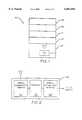
- FIG. 1 of the drawingsis a schematic representation of a multi-unit structure
- FIG. 2 of the drawingsis a schematic block diagram of a multi-unit automation system controller
- FIG. 3 of the drawingsis a block diagram of a single unit of the multi-unit structure of FIG. 1, including various appliances and mechanical systems associated with that particular single unit;
- FIG. 4 of the drawingsis a schematic block diagram of the unit controller of the unit disclosed in FIG. 3 of the drawings;
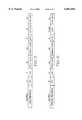
- FIG. 5 of the drawingsis a diagram of an acquisition communication packet
- FIG. 6 of the drawingsis a diagram of a normal communication packet.
- FIG. 1represents an embodiment of the present invention, schematically illustrating a multi-unit structure 5 having a plurality of units 9, 10, 11, 1 2 and 13. While these units are depicted as being on separate floors of a structure, the plurality of units can be configured in any manner, such as multiple units on multiple floors, such as in an apartment building or hotel. Furthermore, it is contemplated that linking every unit of a multi-unit structure would not be necessary or desirable, thus, for purposes of the present application, such units are ignored and not considered part of the plurality of units.
- a structure-wide automation systemis created by providing desired ones of the plurality of units with a respective self-contained unit controller and associated system components, as will be described hereinbelow, and providing one unit associated with the structure with a central controller.
- central controller 100is disposed within unit 9 of multi-unit structure 5.
- Unit 9 of multi-unit structure 5can be thought of as an office, control center, or janitor's apartment.
- central controller 100allows building personnel to monitor (and in various instances control) specific aspects of multi-unit structure 5 from a central location.
- multi-unit automation system controller 100includes internal communication interface 101, processor 102, and external communication interface 103.
- Multi-unit automation system controller 100may include further sub-systems, such as volatile and non-volatile memory, power supplies and the like, as would be known to those of ordinary skill in the art.
- Internal communication interface 101communicates with each of the self-contained automation system controllers (such as reference 15) associated with the plurality of units.
- communication interface 101facilitates communication between multi-unit automation system controller 100 and its unit controllers via a radio frequency link.
- AIMsappliance interface modules
- the initial cost of installing an automated multi-unit structure using the appliance interface modules ("AIMs") and automated system controlis reduced, thereby encouraging adoption of such systems.
- communication according to a standard like CEBus, WHISPER or other automation standardcan be done via twisted pair, coaxial cable, power line or radio frequency communications. Audio/video bus communications and fiber optics communications standards which are currently being developed in the industry, are also contemplated as being used in connection with the present invention.
- communication interface 101can communicate with one of the plurality of unit controllers at a time. Accordingly, communication between the various units and central controller 100 is facilitated using a time-slotted protocol assigned by controller 100.
- a time-slotted protocol assigned by controller 100it is possible to configure communication interface 101 such that it can simultaneously receive and/or transmit to two or more self-contained automated system controllers Nevertheless, as the number of units that can be controlled by a single central controller could number in the hundreds, it is contemplated that some time-slotted protocol would still be required even in a simultaneous reception/transmission embodiment.
- the present inventionutilizes a spread-spectrum communication technique in the 900 Mhz transmission range. While this technique provides various benefits such as lower power requirements and additional security, use of spread-spectrum technology is not necessary to practice a radio frequency embodiment of the present invention.
- Unit 10 of the plurality of units of multi-unit structure 5 containing a self-contained automation control systemis shown in FIG. 3 of the drawings.
- the other unitswould contain similar systems to that associated with unit 10, with each unit system being substantially separate from each other unit system. All such unit systems would be linked to central controller 100 as described above.
- Each unit systemincludes unit controller 15, which is connected, for example--via residential electrical wiring system 20 within unit 10--to HVAC system 25, water heater 30, lights 35, security system 40, internal telephone wiring system 45, gas meter 50, electric meter 55, water meter 60, or other appliances 65 (such as a hot tub, clothes dryer, etc.).
- AIMsappliance interface modules
- AIMscan be attached to both electric-only and gas-operated appliances in various manners that are not pertinent to the present invention. Additionally, some AIMs may contain non-volatile memory, so as to store module addresses and other information and maintain such information even through power failures. Some AIMs are configured solely to monitor appliance operation, others also control appliance operation and still others can actually override built-in electronic or mechanical control for their associated appliance (and/or override otherwise conflicting instructions received from remote sources) upon receipt of appropriate instructions from unit controller 15. Accordingly, various units of multi-unit structure 5 will have differing configurations of AIMs and associated appliances.
- unit controller 15includes appliance communications interface 200, processor 201, and external communication interface 202.
- Appliance communications interface 200 and processor 201are directed toward communicating with, controlling, and obtaining data from various ones of the AIMs disposed within the associated unit of multi-unit structure 5.
- External communication interface 202handles communication between central controller 100 and unit controller 15. As discussed above, in a preferred embodiment, this interface is a spread-spectrum radio frequency link. However, other embodiments using alternate modes of communication are additionally contemplated, particularly for new construction of multi-unit structures.
- communication between external communication interface 20 and central controller 100occur in packets transmitted over the RF link.
- a spread spectrum techniqueis used whereby each packet is transmitted on a pseudo-randomly selected one of a plurality of frequencies.
- the unitssynchronously change their transmission frequencies to another of the plurality of frequencies, as is generally known in the art.
- the present inventionutilizes a table with various pseudo-random sequences from which the central and unit controllers select their hopping sequence.
- central controller 100As a new unit controller is brought into service it will be unknown to central controller 100. Similarly, a unit controller may also fall out of sync with central controller 100. Accordingly, external communication interface 103 of central controller 100 selects an idle channel by listening on a channel and monitoring the Received Signal Strength Indicator (RSSI) for that channel. If the RSSI is lower than a predetermined threshold value then the channel is idle. Otherwise a new channel is selected and the process continues until an idle channel is found. Once found, central controller 100 transmits a synchronization signal for an extended period of time, such as 60 minutes, to allow various unit controllers to synchronize to the central controller.
- RSSIReceived Signal Strength Indicator
- the unit controllerUpon locating the central controller's signal, the unit controller transmits a packet indicating the table-sequence being used by that unit controller and the unit's next frequency selection within that sequence on which the unit controller will "come up on” after it is assigned a time slot by central controller 100.
- the unit and central controllerscommunicate at an assigned time slot, until synchronization is lost or transmission quality is too low.
- external communication interface 103spends much of its time locating and scheduling new unit controllers.
- the transmission packets used in a preferred embodimentare shown in FIGS. 5 and 6.
- the packet of FIG. 5is used during acquisition of synchronization and the packet of FIG. 6 during normal communication.
- Each packetincludes a preamble; "SPC” [Charles: what is this?]; message priority indicator ("CTRL”); the unique base address of central controller 100; the unique address of the unit controller involved with the present communication; a data length field (“LEN”); data comprising (i) for the acquisition packet, the location within the hopping sequence ("HOP SEQ") or (ii) for the communication packet, data associated with a command; and an error-detecting code ("CHK SUM").
- Each preambleis suited to its particular function. For instance, the acquisition preamble is longer than the normal preamble thus increasing the potential for detection of the packet by the central controller so as to facilitate earliest synchronization. Otherwise, the preambles may be virtually identical.
- the message priority indicatorcan support normal, priority and special messages.
- a priority messageis acted upon quicker in central controller 100.
- a special messageoccurs whenever unit controller 15 transmits outside of its regularly scheduled time-slot. Such transmission may occur on the occurrence of a hazardous condition or alarm situation.
- Each commandincludes, in addition to the command-type, the device type (gas meter, water meter, water heater, flow station, etc.).
- the error-detecting codepreferably comprises a "Flecher's Checksum.”
- Other error-detecting codesare known within the art that are similarly suitable for this application, such as a standard checksum, cyclic redundancy checking, etc.
- a standard checksumcyclic redundancy checking, etc.
- the external communication interface 203 of unit controller 15may report data only if there was a value change, However, to facilitate a "handshaking" protocol used to ensure receipt of the various transmissions, the unit will still provide an abbreviated response to central controller 100. This abbreviated response will conserve power--particularly significant if the radio is battery-powered--as well as minimize the time required for transmission and any resulting radio interface caused by the transmission.
- external communication interface 203 of unit controller 15may further include volatile memory for the storage of data transmitted by unit controller 15 to central controller 100.
- external communication interface 203could continue to send a data packet until the unit controller is assured of proper receipt.
- the transmitted datais saved in case of data loss during transmission at least until an acknowledgment is received from central controller 100. Failure to receive a return acknowledgment signal from central controller 100 (or a unit controller) can be due to any number of environmental and electrical factors.
- the external communication interfacestores data along with the time from an internal timestamp counter.
- the internal timestamp counterutilizes a realtime clock.
- the use of a realtime clockrequires only conversion from seconds to hours:minutes:seconds.
- Another embodimentwould simply use a timestamp counter that is based on the seconds maintained by units, thus, avoiding the overhead associated with a real-time clock.
- the value of the timestamp countermust be continually verified and, if necessary, corrected by the central controller 100, so as to facilitate synchronization of the logged data in kept real time by central controller 100 and the various utilities in the event that data transmission is required from the log. Of course, this verification and correction also facilitates time-division multiplexing.
- Processor 102 of central controller 100is a programmable processing device capable of a variety of operations. Normally associated with processor 102 is volatile and non-volatile memory to facilitate the various functions of central controller 100. These functions are related to the foregoing operations described with respect to facilitating communication between central controller 100 and the plurality of units.
- processor 102must be configured and/or programmed to process the various data transmitted from each of the plurality of units in multi-unit structure 5, as well as the data transmitted by the utilities via external communication interface 103. For instance, via any and all of the unit controllers, central controller 100 will receive information either directly or extrapolated from the various AIMs disposed in the various spaces.
- each unithas its own gas furnace
- those associated AIMs1) monitor instantaneous and total natural or LP gas usage and electric usage of the furnace (and air conditioner); 2) provide inputs for setting nominal firing rates for the burner and power consumption of electrical devices, such as a compressor, during installation, so as to enable reporting of gas and electric power consumption during operation; 3) monitor supply air and return air temperatures (from suitably placed temperature sensors within the furnace); 4) have input ports for receiving data from externally placed sensors, such as temperature sensors in individual rooms for actual room temperature sensing; 5) have input ports for receiving remote commands for heating, raising or lowering of set points for heating and cooling, etc., from remote sensors or full-function thermostats, remote automation controllers or other devices; 6) monitor and report, to the automation system controller, the status of a pilot flame, gas burner, stack damper, induced draft blower, circulating blower, etc.; and 7) monitor and report, to the automation system controller, failures such as blocked stack, clogged filter, pilot or main burner failure, compressor failure or failure of
- the central controllerputs building owners in a position to acquire much more accurate and detailed information regarding patterns of power usage, incidence of usage of failing or inefficient equipment and the like, which would assist the owner in setting rents, planning appliance upgrades and repairing various related aspects of the structure that directly affect power-usage.
- the residence's gas consumption datamight appear to be inconsistent with the gas usage data from other similarly situated units. This may indicate a faulty furnace, water heater and other gas appliances. This data may alternatively indicate poor thermal insulation or a resident overheating the unit.
- the reason for the aberrationcan be determined.
- This informationcan be used to protect tenants and the structure from potential appliance malfunction. Further, a cost savings may be achieved by reducing the amount of time, labor and effort involved in gathering data and locating faulty appliances for replacement, thus, leading to earlier replacement and saved utility costs.
- central controller 100The control aspects provided by central controller 100 via each of the unit controllers also provide significant cost benefits. For instance, if the building personnel know that a unit is vacant, they can control the environment of that unit to reflect the vacancy and, thus, save on certain utility expenses. One example of this is a residence hall during a vacation period.
- central controller 100further includes external communication interface 103.
- External communication interface 103facilitates communication between central controller 100 and various utility companies.
- external communication interface 103may comprise a modem configured to communicate with one or more utility companies via a standard telephone line.
- external communication interface 103may comprise an RF transmitter/receiver unit configured to communicate with one or more utility companies.
- external communication interface 103may comprise a cable TV system interface. The connection through external communication interface 103 from the utility to processor 102 is intended to be complete so as to permit the transmission of inquiries and/or data to or from the utility to be passed through from or to the system at all times.
- each central controller 100 and multi-structure unit 5is assigned a unique address. Accordingly, external communication interface 103 performs a gate-keeping function by allowing only messages intended for the associated controller 100 to be passed thereto. Further, external communication interface 103 also ensures transmission to the utility.
- connection of the various units to central controller 100permits various advantageous cost and effort-saving functions to be possible.
- the building personnelwill be able to monitor individual unit usages throughout multi-unit structure 5. Accordingly, if there are any aberrations, such as abnormally high gas usage, this may indicate various correctable problems that might otherwise go unnoticed.
- building personnelmay even undertake some limited override control of the operation of the appliances and mechanical systems of one or more units. For instance, in a residence hall, the heat could be lowered in one or more units during vacation periods.
- connection maintained with the utility companiesmay lead to further potential control situations. For instance, if the utility were to perceive that a potential power shortage ("brownout") were developing, or that there were a dangerous gas pressure instability occurring, the utility could then communicate with central controller 100, which, in turn, would communicate with the unit controllers associated with the various units toward ultimately shutting (or slowing) down various appliances.
- brownoutpotential power shortage
Landscapes
- Physics & Mathematics (AREA)
- General Physics & Mathematics (AREA)
- Engineering & Computer Science (AREA)
- Automation & Control Theory (AREA)
- Selective Calling Equipment (AREA)
Abstract
Description
Claims (9)
Priority Applications (3)
| Application Number | Priority Date | Filing Date | Title |
|---|---|---|---|
| US08/852,102US6061604A (en) | 1997-05-06 | 1997-05-06 | RF base repeater for automated residence management system |
| PCT/US1998/009266WO1998050833A1 (en) | 1997-05-06 | 1998-05-06 | Rf base repeater for automated residence management system |
| AU73705/98AAU7370598A (en) | 1997-05-06 | 1998-05-06 | Rf base repeater for automated residence management system |
Applications Claiming Priority (1)
| Application Number | Priority Date | Filing Date | Title |
|---|---|---|---|
| US08/852,102US6061604A (en) | 1997-05-06 | 1997-05-06 | RF base repeater for automated residence management system |
Publications (1)
| Publication Number | Publication Date |
|---|---|
| US6061604Atrue US6061604A (en) | 2000-05-09 |
Family
ID=25312500
Family Applications (1)
| Application Number | Title | Priority Date | Filing Date |
|---|---|---|---|
| US08/852,102Expired - Fee RelatedUS6061604A (en) | 1997-05-06 | 1997-05-06 | RF base repeater for automated residence management system |
Country Status (3)
| Country | Link |
|---|---|
| US (1) | US6061604A (en) |
| AU (1) | AU7370598A (en) |
| WO (1) | WO1998050833A1 (en) |
Cited By (71)
| Publication number | Priority date | Publication date | Assignee | Title |
|---|---|---|---|---|
| US20020012323A1 (en)* | 1999-03-18 | 2002-01-31 | Petite Thomas D. | Systems and methods for enabling a mobile user to notify an automated monitoring system of an emergency situation |
| US20020072809A1 (en)* | 2000-10-24 | 2002-06-13 | Michael Zuraw | Microcomputer control of physical devices |
| US20020125998A1 (en)* | 1998-06-22 | 2002-09-12 | Petite Thomas D. | System and method for monitoring and controlling remote devices |
| US20020193888A1 (en)* | 2001-06-19 | 2002-12-19 | Bandu Wewalaarachchi | Method and apparatus for automatically generating a SCADA system |
| US20030007503A1 (en)* | 2000-12-26 | 2003-01-09 | Wolfgang Daum | Method and apparatus for interfacing a power line carrier and an appliance |
| US20030046377A1 (en)* | 2000-12-27 | 2003-03-06 | Wolfgang Daum | Method and apparatus for appliance service diagnostics |
| US6552525B2 (en)* | 2001-03-14 | 2003-04-22 | General Electric Company | System and method for scheduling and monitoring electrical device usage |
| US20030088318A1 (en)* | 2001-10-25 | 2003-05-08 | Fuji Xerox Co., Ltd. | Device control system |
| US6693531B2 (en)* | 2002-04-18 | 2004-02-17 | Uponor Canada Inc. | Integrated control of a system |
| US6816538B2 (en) | 2002-06-26 | 2004-11-09 | Elster Electricity, Llc | Frequency hopping spread spectrum decoder |
| US20040233281A1 (en)* | 2003-05-20 | 2004-11-25 | Tolmei Vincent Ronald | Visual and audible surveillance system, using CATV cable plant distribution equipment, that enables the public to monitor, on television receivers, "at risk" areas or facilities 24 hours per day 7 days per week |
| US6836737B2 (en) | 2000-08-09 | 2004-12-28 | Statsignal Systems, Inc. | Systems and methods for providing remote monitoring of consumption for a utility meter |
| US6850149B2 (en)* | 2000-11-27 | 2005-02-01 | Lg Electronics Inc. | Network control method and apparatus for home appliance |
| US6888876B1 (en) | 2001-12-21 | 2005-05-03 | Elster Electricity, Llc | Frequency hopping spread spectrum communications system |
| US6891838B1 (en) | 1998-06-22 | 2005-05-10 | Statsignal Ipc, Llc | System and method for monitoring and controlling residential devices |
| US20050116836A1 (en)* | 2003-11-26 | 2005-06-02 | Triacta Power Technologies Inc. | Method and apparatus for monitoring power consumption on power distribution circuits for centralized analysis |
| US6922558B2 (en)* | 1998-03-06 | 2005-07-26 | Don Delp | Integrated building control and information system with wireless networking |
| US7020178B2 (en) | 2002-06-26 | 2006-03-28 | Elster Electricity, Llc | Microprocessor decoder frequency hopping spread spectrum communications receiver |
| US7079810B2 (en) | 1997-02-14 | 2006-07-18 | Statsignal Ipc, Llc | System and method for communicating with a remote communication unit via the public switched telephone network (PSTN) |
| US7103511B2 (en) | 1998-10-14 | 2006-09-05 | Statsignal Ipc, Llc | Wireless communication networks for providing remote monitoring of devices |
| US7126494B2 (en) | 1997-02-12 | 2006-10-24 | Elster Electricity, Llc | Remote access to electronic meters using a TCP/IP protocol suite |
| US7137550B1 (en) | 1997-02-14 | 2006-11-21 | Statsignal Ipc, Llc | Transmitter for accessing automated financial transaction machines |
| US7142106B2 (en) | 2004-06-15 | 2006-11-28 | Elster Electricity, Llc | System and method of visualizing network layout and performance characteristics in a wireless network |
| US7145474B2 (en) | 2002-06-27 | 2006-12-05 | Elster Electricity, Llc | Dynamic self-configuring metering network |
| US7170425B2 (en) | 2004-09-24 | 2007-01-30 | Elster Electricity, Llc | System and method for creating multiple operating territories within a meter reading system |
| US7176807B2 (en) | 2004-09-24 | 2007-02-13 | Elster Electricity, Llc | System for automatically enforcing a demand reset in a fixed network of electricity meters |
| US7187906B2 (en) | 2004-04-26 | 2007-03-06 | Elster Electricity, Llc | Method and system for configurable qualification and registration in a fixed network automated meter reading system |
| US7239250B2 (en) | 2004-04-26 | 2007-07-03 | Elster Electricity, Llc | System and method for improved transmission of meter data |
| US7262709B2 (en) | 2004-04-26 | 2007-08-28 | Elster Electricity, Llc | System and method for efficient configuration in a fixed network automated meter reading system |
| US7295128B2 (en) | 1998-06-22 | 2007-11-13 | Sipco, Llc | Smoke detection methods, devices, and systems |
| US7308369B2 (en) | 2005-09-28 | 2007-12-11 | Elster Electricity Llc | Ensuring automatic season change demand resets in a mesh type network of telemetry devices |
| US7308370B2 (en) | 2005-03-22 | 2007-12-11 | Elster Electricity Llc | Using a fixed network wireless data collection system to improve utility responsiveness to power outages |
| US7312721B2 (en) | 2002-06-28 | 2007-12-25 | Elster Electricity, Llc | Data collector for an automated meter reading system |
| US7327998B2 (en) | 2004-12-22 | 2008-02-05 | Elster Electricity, Llc | System and method of providing a geographic view of nodes in a wireless network |
| US7340509B2 (en) | 2002-07-18 | 2008-03-04 | General Electric Company | Reconfigurable appliance control system |
| US7346463B2 (en) | 2001-08-09 | 2008-03-18 | Hunt Technologies, Llc | System for controlling electrically-powered devices in an electrical network |
| US20080092227A1 (en)* | 1999-07-01 | 2008-04-17 | International Business Machines Corporation | Security For Network-Connected Vehicles and Other Network-Connected Processing Environments |
| US7397907B2 (en) | 1997-02-14 | 2008-07-08 | Sipco, Llc | Multi-function general purpose transceiver |
| US7424527B2 (en) | 2001-10-30 | 2008-09-09 | Sipco, Llc | System and method for transmitting pollution information over an integrated wireless network |
| US7427927B2 (en) | 2006-02-16 | 2008-09-23 | Elster Electricity, Llc | In-home display communicates with a fixed network meter reading system |
| US7480501B2 (en) | 2001-10-24 | 2009-01-20 | Statsignal Ipc, Llc | System and method for transmitting an emergency message over an integrated wireless network |
| US7495578B2 (en) | 2005-09-02 | 2009-02-24 | Elster Electricity, Llc | Multipurpose interface for an automated meter reading device |
| US7545285B2 (en) | 2006-02-16 | 2009-06-09 | Elster Electricity, Llc | Load control unit in communication with a fixed network meter reading system |
| US20090151190A1 (en)* | 2007-12-12 | 2009-06-18 | Richard Anderson | Drying system and method of using same |
| US20090185601A1 (en)* | 2003-05-06 | 2009-07-23 | Britta Felbecker | Channel qualification for an adaptive frequency hopping method by means of bit or packet error rate measurement and simultaneous field strength measurement |
| US7650425B2 (en) | 1999-03-18 | 2010-01-19 | Sipco, Llc | System and method for controlling communication between a host computer and communication devices associated with remote devices in an automated monitoring system |
| US7653443B2 (en) | 2007-03-01 | 2010-01-26 | Daniel Flohr | Methods, systems, circuits and computer program products for electrical service demand management |
| US7697492B2 (en) | 1998-06-22 | 2010-04-13 | Sipco, Llc | Systems and methods for monitoring and controlling remote devices |
| US7702594B2 (en) | 2004-09-24 | 2010-04-20 | Elster Electricity, Llc | System and method for automated configuration of meters |
| US7742430B2 (en) | 2004-09-24 | 2010-06-22 | Elster Electricity, Llc | System for automated management of spontaneous node migration in a distributed fixed wireless network |
| US7756086B2 (en) | 2004-03-03 | 2010-07-13 | Sipco, Llc | Method for communicating in dual-modes |
| US20110037455A1 (en)* | 2009-08-17 | 2011-02-17 | Oren Navot | System for measuring electrical power |
| US20110140901A1 (en)* | 2009-12-16 | 2011-06-16 | Schneider Electric USA, Inc. | Point-of-use status indicator |
| US8000314B2 (en) | 1996-12-06 | 2011-08-16 | Ipco, Llc | Wireless network system and method for providing same |
| US8031650B2 (en) | 2004-03-03 | 2011-10-04 | Sipco, Llc | System and method for monitoring remote devices with a dual-mode wireless communication protocol |
| US8073384B2 (en) | 2006-12-14 | 2011-12-06 | Elster Electricity, Llc | Optimization of redundancy and throughput in an automated meter data collection system using a wireless network |
| US8203463B2 (en) | 2009-02-13 | 2012-06-19 | Elster Electricity Llc | Wakeup and interrogation of meter-reading devices using licensed narrowband and unlicensed wideband radio communication |
| US8320302B2 (en) | 2007-04-20 | 2012-11-27 | Elster Electricity, Llc | Over the air microcontroller flash memory updates |
| US8410931B2 (en) | 1998-06-22 | 2013-04-02 | Sipco, Llc | Mobile inventory unit monitoring systems and methods |
| US8489063B2 (en) | 2001-10-24 | 2013-07-16 | Sipco, Llc | Systems and methods for providing emergency messages to a mobile device |
| US8525692B2 (en) | 2008-06-13 | 2013-09-03 | Elster Solutions, Llc | Techniques for limiting demand from an electricity meter with an installed relay |
| US20130297075A1 (en)* | 2012-05-07 | 2013-11-07 | Trane International, Inc. | Control system |
| US8787246B2 (en) | 2009-02-03 | 2014-07-22 | Ipco, Llc | Systems and methods for facilitating wireless network communication, satellite-based wireless network systems, and aircraft-based wireless network systems, and related methods |
| US20140281076A1 (en)* | 2013-03-15 | 2014-09-18 | Apple Inc. | Methods and apparatus for multi-drop digital bus |
| US9439126B2 (en) | 2005-01-25 | 2016-09-06 | Sipco, Llc | Wireless network protocol system and methods |
| US9612132B2 (en) | 2007-12-26 | 2017-04-04 | Elster Solutions, Llc | Optimized data collection in a wireless fixed network metering system |
| US10085224B2 (en) | 2014-11-19 | 2018-09-25 | Apple Inc. | Methods and apparatus for synchronization of media playback within a wireless network |
| US20180356111A1 (en)* | 2017-06-09 | 2018-12-13 | Johnson Controls Technology Company | Thermostat with efficient wireless data transmission |
| US10868857B2 (en) | 2017-04-21 | 2020-12-15 | Johnson Controls Technology Company | Building management system with distributed data collection and gateway services |
| US11032172B2 (en) | 2017-06-09 | 2021-06-08 | Johnson Controls Technology Company | Asynchronous wireless data transmission system and method for asynchronously transmitting samples of a measured variable by a wireless sensor |
| US11039408B2 (en) | 2012-06-07 | 2021-06-15 | Apple Inc. | Methods and apparatus for synchronization among integrated circuits within a wireless network |
Families Citing this family (2)
| Publication number | Priority date | Publication date | Assignee | Title |
|---|---|---|---|---|
| SE9900510D0 (en) | 1999-02-15 | 1999-02-15 | Iro Patent Ag | Yarn processing system and method to operate a yarn processing system |
| DE10000609B4 (en)* | 2000-01-10 | 2006-04-13 | Gira Giersiepen Gmbh & Co. Kg | Interface device for a data connection between an electrical installation system and a Komminikationssystem and equipped therewith electrical installation system |
Citations (30)
| Publication number | Priority date | Publication date | Assignee | Title |
|---|---|---|---|---|
| US3881325A (en)* | 1973-09-21 | 1975-05-06 | Tenna Corp | Override clutch |
| US4310896A (en)* | 1979-11-13 | 1982-01-12 | General Electric Company | Method of interfacing remote units to a central microprocessor |
| US4360881A (en)* | 1980-07-07 | 1982-11-23 | Martinson John R | Energy consumption control system and method |
| US4389577A (en)* | 1982-04-14 | 1983-06-21 | Honeywell Inc. | Apparatus for power load-shedding with auxiliary commandable thermostat |
| US4421268A (en)* | 1980-10-17 | 1983-12-20 | Honeywell Inc. | Integrated control system using a microprocessor |
| US4508261A (en)* | 1982-01-28 | 1985-04-02 | Gerald Blank | Hot water control and management system |
| US4519540A (en)* | 1981-08-27 | 1985-05-28 | Societe Anonyme Saunier Duval Eau Chaude Chauffage - S.D.E.C.C. | Sealed gas heater with forced draft and regulation by microprocessor |
| US4567557A (en)* | 1983-02-23 | 1986-01-28 | Burns Martin J | Building intelligence system |
| US4607787A (en)* | 1985-04-12 | 1986-08-26 | Rogers Iii Charles F | Electronic control and method for increasing efficiency of heating |
| US4644320A (en)* | 1984-09-14 | 1987-02-17 | Carr R Stephen | Home energy monitoring and control system |
| US4703306A (en)* | 1986-09-26 | 1987-10-27 | The Maytag Company | Appliance system |
| US4799059A (en)* | 1986-03-14 | 1989-01-17 | Enscan, Inc. | Automatic/remote RF instrument monitoring system |
| US4819180A (en)* | 1987-02-13 | 1989-04-04 | Dencor Energy Cost Controls, Inc. | Variable-limit demand controller for metering electrical energy |
| US4888706A (en)* | 1982-07-06 | 1989-12-19 | Institute Of Gas Technology | Fluid distribution to multiple users through distributed intelligence sub-centers |
| US5032833A (en)* | 1989-04-27 | 1991-07-16 | Schlumberger Industries, Inc. | Adaptive network routing for power line communications |
| US5056107A (en)* | 1990-02-15 | 1991-10-08 | Iris Systems Inc. | Radio communication network for remote data generating stations |
| US5073862A (en)* | 1987-08-26 | 1991-12-17 | Carlson Peter J | Method and apparatus for diagnosing problems with the thermodynamic performance of a heat engine |
| US5126934A (en)* | 1989-06-09 | 1992-06-30 | Smart House, L.P. | Gas distribution system |
| US5168170A (en)* | 1989-09-07 | 1992-12-01 | Lexington Power Management Corporation | Subscriber electric power load control system |
| US5186386A (en)* | 1990-02-09 | 1993-02-16 | Inter-City Products Corporation (Usa) | Two stage furnace control |
| US5270704A (en)* | 1990-06-04 | 1993-12-14 | Union Electrica De Canarias, S.A. | Autonomous pulse reading and recording system |
| US5323307A (en)* | 1990-11-29 | 1994-06-21 | Square D Company | Power management and automation system |
| US5350114A (en)* | 1993-07-21 | 1994-09-27 | The Budd Company | Microprocessor controller for diesel fuel fired heater |
| EP0620631A1 (en)* | 1993-04-15 | 1994-10-19 | ZELTRON S.p.A. | Management system for domestic electric loads |
| WO1996012993A1 (en)* | 1994-10-24 | 1996-05-02 | Fisher-Rosemount Systems, Inc. | Apparatus for providing access to field devices in a distributed control system |
| US5528621A (en)* | 1989-06-29 | 1996-06-18 | Symbol Technologies, Inc. | Packet data communication system |
| US5533025A (en)* | 1994-09-26 | 1996-07-02 | International Business Machines Corporation | Robust frequency management and acquisition in a wireless local area network that uses frequency-hopping radios |
| US5572438A (en)* | 1995-01-05 | 1996-11-05 | Teco Energy Management Services | Engery management and building automation system |
| US5706191A (en)* | 1995-01-19 | 1998-01-06 | Gas Research Institute | Appliance interface apparatus and automated residence management system |
| US5726644A (en)* | 1995-06-30 | 1998-03-10 | Philips Electronics North America Corporation | Lighting control system with packet hopping communication |
- 1997
- 1997-05-06USUS08/852,102patent/US6061604A/ennot_activeExpired - Fee Related
- 1998
- 1998-05-06WOPCT/US1998/009266patent/WO1998050833A1/enactiveApplication Filing
- 1998-05-06AUAU73705/98Apatent/AU7370598A/ennot_activeAbandoned
Patent Citations (30)
| Publication number | Priority date | Publication date | Assignee | Title |
|---|---|---|---|---|
| US3881325A (en)* | 1973-09-21 | 1975-05-06 | Tenna Corp | Override clutch |
| US4310896A (en)* | 1979-11-13 | 1982-01-12 | General Electric Company | Method of interfacing remote units to a central microprocessor |
| US4360881A (en)* | 1980-07-07 | 1982-11-23 | Martinson John R | Energy consumption control system and method |
| US4421268A (en)* | 1980-10-17 | 1983-12-20 | Honeywell Inc. | Integrated control system using a microprocessor |
| US4519540A (en)* | 1981-08-27 | 1985-05-28 | Societe Anonyme Saunier Duval Eau Chaude Chauffage - S.D.E.C.C. | Sealed gas heater with forced draft and regulation by microprocessor |
| US4508261A (en)* | 1982-01-28 | 1985-04-02 | Gerald Blank | Hot water control and management system |
| US4389577A (en)* | 1982-04-14 | 1983-06-21 | Honeywell Inc. | Apparatus for power load-shedding with auxiliary commandable thermostat |
| US4888706A (en)* | 1982-07-06 | 1989-12-19 | Institute Of Gas Technology | Fluid distribution to multiple users through distributed intelligence sub-centers |
| US4567557A (en)* | 1983-02-23 | 1986-01-28 | Burns Martin J | Building intelligence system |
| US4644320A (en)* | 1984-09-14 | 1987-02-17 | Carr R Stephen | Home energy monitoring and control system |
| US4607787A (en)* | 1985-04-12 | 1986-08-26 | Rogers Iii Charles F | Electronic control and method for increasing efficiency of heating |
| US4799059A (en)* | 1986-03-14 | 1989-01-17 | Enscan, Inc. | Automatic/remote RF instrument monitoring system |
| US4703306A (en)* | 1986-09-26 | 1987-10-27 | The Maytag Company | Appliance system |
| US4819180A (en)* | 1987-02-13 | 1989-04-04 | Dencor Energy Cost Controls, Inc. | Variable-limit demand controller for metering electrical energy |
| US5073862A (en)* | 1987-08-26 | 1991-12-17 | Carlson Peter J | Method and apparatus for diagnosing problems with the thermodynamic performance of a heat engine |
| US5032833A (en)* | 1989-04-27 | 1991-07-16 | Schlumberger Industries, Inc. | Adaptive network routing for power line communications |
| US5126934A (en)* | 1989-06-09 | 1992-06-30 | Smart House, L.P. | Gas distribution system |
| US5528621A (en)* | 1989-06-29 | 1996-06-18 | Symbol Technologies, Inc. | Packet data communication system |
| US5168170A (en)* | 1989-09-07 | 1992-12-01 | Lexington Power Management Corporation | Subscriber electric power load control system |
| US5186386A (en)* | 1990-02-09 | 1993-02-16 | Inter-City Products Corporation (Usa) | Two stage furnace control |
| US5056107A (en)* | 1990-02-15 | 1991-10-08 | Iris Systems Inc. | Radio communication network for remote data generating stations |
| US5270704A (en)* | 1990-06-04 | 1993-12-14 | Union Electrica De Canarias, S.A. | Autonomous pulse reading and recording system |
| US5323307A (en)* | 1990-11-29 | 1994-06-21 | Square D Company | Power management and automation system |
| EP0620631A1 (en)* | 1993-04-15 | 1994-10-19 | ZELTRON S.p.A. | Management system for domestic electric loads |
| US5350114A (en)* | 1993-07-21 | 1994-09-27 | The Budd Company | Microprocessor controller for diesel fuel fired heater |
| US5533025A (en)* | 1994-09-26 | 1996-07-02 | International Business Machines Corporation | Robust frequency management and acquisition in a wireless local area network that uses frequency-hopping radios |
| WO1996012993A1 (en)* | 1994-10-24 | 1996-05-02 | Fisher-Rosemount Systems, Inc. | Apparatus for providing access to field devices in a distributed control system |
| US5572438A (en)* | 1995-01-05 | 1996-11-05 | Teco Energy Management Services | Engery management and building automation system |
| US5706191A (en)* | 1995-01-19 | 1998-01-06 | Gas Research Institute | Appliance interface apparatus and automated residence management system |
| US5726644A (en)* | 1995-06-30 | 1998-03-10 | Philips Electronics North America Corporation | Lighting control system with packet hopping communication |
Cited By (119)
| Publication number | Priority date | Publication date | Assignee | Title |
|---|---|---|---|---|
| US8233471B2 (en) | 1996-12-06 | 2012-07-31 | Ipco, Llc | Wireless network system and method for providing same |
| US8625496B2 (en) | 1996-12-06 | 2014-01-07 | Ipco, Llc | Wireless network system and method for providing same |
| US8000314B2 (en) | 1996-12-06 | 2011-08-16 | Ipco, Llc | Wireless network system and method for providing same |
| US8982856B2 (en) | 1996-12-06 | 2015-03-17 | Ipco, Llc | Systems and methods for facilitating wireless network communication, satellite-based wireless network systems, and aircraft-based wireless network systems, and related methods |
| US7126494B2 (en) | 1997-02-12 | 2006-10-24 | Elster Electricity, Llc | Remote access to electronic meters using a TCP/IP protocol suite |
| US7397907B2 (en) | 1997-02-14 | 2008-07-08 | Sipco, Llc | Multi-function general purpose transceiver |
| US7137550B1 (en) | 1997-02-14 | 2006-11-21 | Statsignal Ipc, Llc | Transmitter for accessing automated financial transaction machines |
| US7079810B2 (en) | 1997-02-14 | 2006-07-18 | Statsignal Ipc, Llc | System and method for communicating with a remote communication unit via the public switched telephone network (PSTN) |
| US6922558B2 (en)* | 1998-03-06 | 2005-07-26 | Don Delp | Integrated building control and information system with wireless networking |
| US7719440B2 (en)* | 1998-03-06 | 2010-05-18 | Don Delp | Integrated building control and information system with wireless networking |
| US20060159043A1 (en)* | 1998-03-06 | 2006-07-20 | Don Delp | Integrated building control and information system with wireless networking |
| US8964708B2 (en) | 1998-06-22 | 2015-02-24 | Sipco Llc | Systems and methods for monitoring and controlling remote devices |
| US8212667B2 (en) | 1998-06-22 | 2012-07-03 | Sipco, Llc | Automotive diagnostic data monitoring systems and methods |
| US9571582B2 (en) | 1998-06-22 | 2017-02-14 | Sipco, Llc | Systems and methods for monitoring and controlling remote devices |
| US7295128B2 (en) | 1998-06-22 | 2007-11-13 | Sipco, Llc | Smoke detection methods, devices, and systems |
| US6891838B1 (en) | 1998-06-22 | 2005-05-10 | Statsignal Ipc, Llc | System and method for monitoring and controlling residential devices |
| US8223010B2 (en) | 1998-06-22 | 2012-07-17 | Sipco Llc | Systems and methods for monitoring vehicle parking |
| US9430936B2 (en) | 1998-06-22 | 2016-08-30 | Sipco Llc | Systems and methods for monitoring and controlling remote devices |
| US8410931B2 (en) | 1998-06-22 | 2013-04-02 | Sipco, Llc | Mobile inventory unit monitoring systems and methods |
| US8064412B2 (en) | 1998-06-22 | 2011-11-22 | Sipco, Llc | Systems and methods for monitoring conditions |
| US7053767B2 (en) | 1998-06-22 | 2006-05-30 | Statsignal Systems, Inc. | System and method for monitoring and controlling remote devices |
| US20020125998A1 (en)* | 1998-06-22 | 2002-09-12 | Petite Thomas D. | System and method for monitoring and controlling remote devices |
| US8013732B2 (en) | 1998-06-22 | 2011-09-06 | Sipco, Llc | Systems and methods for monitoring and controlling remote devices |
| US9691263B2 (en) | 1998-06-22 | 2017-06-27 | Sipco, Llc | Systems and methods for monitoring conditions |
| US9129497B2 (en) | 1998-06-22 | 2015-09-08 | Statsignal Systems, Inc. | Systems and methods for monitoring conditions |
| US7697492B2 (en) | 1998-06-22 | 2010-04-13 | Sipco, Llc | Systems and methods for monitoring and controlling remote devices |
| US7103511B2 (en) | 1998-10-14 | 2006-09-05 | Statsignal Ipc, Llc | Wireless communication networks for providing remote monitoring of devices |
| US8930571B2 (en) | 1999-03-18 | 2015-01-06 | Sipco, LLP | Systems and methods for controlling communication between a host computer and communication devices |
| US20020012323A1 (en)* | 1999-03-18 | 2002-01-31 | Petite Thomas D. | Systems and methods for enabling a mobile user to notify an automated monitoring system of an emergency situation |
| US8924587B2 (en) | 1999-03-18 | 2014-12-30 | Sipco, Llc | Systems and methods for controlling communication between a host computer and communication devices |
| US8924588B2 (en) | 1999-03-18 | 2014-12-30 | Sipco, Llc | Systems and methods for controlling communication between a host computer and communication devices |
| US7650425B2 (en) | 1999-03-18 | 2010-01-19 | Sipco, Llc | System and method for controlling communication between a host computer and communication devices associated with remote devices in an automated monitoring system |
| US7263073B2 (en) | 1999-03-18 | 2007-08-28 | Statsignal Ipc, Llc | Systems and methods for enabling a mobile user to notify an automated monitoring system of an emergency situation |
| US7797737B2 (en)* | 1999-07-01 | 2010-09-14 | International Business Machines Corporation | Security for network-connected vehicles and other network-connected processing environments |
| US20080092227A1 (en)* | 1999-07-01 | 2008-04-17 | International Business Machines Corporation | Security For Network-Connected Vehicles and Other Network-Connected Processing Environments |
| US7209840B2 (en) | 2000-08-09 | 2007-04-24 | Hunt Technologies, Llc | Systems and methods for providing remote monitoring of electricity consumption for an electric meter |
| US6836737B2 (en) | 2000-08-09 | 2004-12-28 | Statsignal Systems, Inc. | Systems and methods for providing remote monitoring of consumption for a utility meter |
| US20050043059A1 (en)* | 2000-08-09 | 2005-02-24 | Petite Thomas D. | Systems and methods for providing remote monitoring of electricity consumption for an electric meter |
| US20020072809A1 (en)* | 2000-10-24 | 2002-06-13 | Michael Zuraw | Microcomputer control of physical devices |
| US6850149B2 (en)* | 2000-11-27 | 2005-02-01 | Lg Electronics Inc. | Network control method and apparatus for home appliance |
| US7170405B2 (en) | 2000-12-26 | 2007-01-30 | General Electric Company | Method and apparatus for interfacing a power line carrier and an appliance |
| US20030007503A1 (en)* | 2000-12-26 | 2003-01-09 | Wolfgang Daum | Method and apparatus for interfacing a power line carrier and an appliance |
| US20030046377A1 (en)* | 2000-12-27 | 2003-03-06 | Wolfgang Daum | Method and apparatus for appliance service diagnostics |
| US6552525B2 (en)* | 2001-03-14 | 2003-04-22 | General Electric Company | System and method for scheduling and monitoring electrical device usage |
| US6957110B2 (en)* | 2001-06-19 | 2005-10-18 | Eutech Cybernetics | Method and apparatus for automatically generating a SCADA system |
| US20020193888A1 (en)* | 2001-06-19 | 2002-12-19 | Bandu Wewalaarachchi | Method and apparatus for automatically generating a SCADA system |
| US7346463B2 (en) | 2001-08-09 | 2008-03-18 | Hunt Technologies, Llc | System for controlling electrically-powered devices in an electrical network |
| US8489063B2 (en) | 2001-10-24 | 2013-07-16 | Sipco, Llc | Systems and methods for providing emergency messages to a mobile device |
| US8666357B2 (en) | 2001-10-24 | 2014-03-04 | Sipco, Llc | System and method for transmitting an emergency message over an integrated wireless network |
| US7480501B2 (en) | 2001-10-24 | 2009-01-20 | Statsignal Ipc, Llc | System and method for transmitting an emergency message over an integrated wireless network |
| US10149129B2 (en) | 2001-10-24 | 2018-12-04 | Sipco, Llc | Systems and methods for providing emergency messages to a mobile device |
| US9282029B2 (en) | 2001-10-24 | 2016-03-08 | Sipco, Llc. | System and method for transmitting an emergency message over an integrated wireless network |
| US10687194B2 (en) | 2001-10-24 | 2020-06-16 | Sipco, Llc | Systems and methods for providing emergency messages to a mobile device |
| US9615226B2 (en) | 2001-10-24 | 2017-04-04 | Sipco, Llc | System and method for transmitting an emergency message over an integrated wireless network |
| US20030088318A1 (en)* | 2001-10-25 | 2003-05-08 | Fuji Xerox Co., Ltd. | Device control system |
| US7176785B2 (en)* | 2001-10-25 | 2007-02-13 | Fuji Xerox Co., Ltd. | Device control system |
| US9515691B2 (en) | 2001-10-30 | 2016-12-06 | Sipco, Llc. | System and method for transmitting pollution information over an integrated wireless network |
| US7424527B2 (en) | 2001-10-30 | 2008-09-09 | Sipco, Llc | System and method for transmitting pollution information over an integrated wireless network |
| US8171136B2 (en) | 2001-10-30 | 2012-05-01 | Sipco, Llc | System and method for transmitting pollution information over an integrated wireless network |
| US9111240B2 (en) | 2001-10-30 | 2015-08-18 | Sipco, Llc. | System and method for transmitting pollution information over an integrated wireless network |
| US6888876B1 (en) | 2001-12-21 | 2005-05-03 | Elster Electricity, Llc | Frequency hopping spread spectrum communications system |
| US6693531B2 (en)* | 2002-04-18 | 2004-02-17 | Uponor Canada Inc. | Integrated control of a system |
| US7020178B2 (en) | 2002-06-26 | 2006-03-28 | Elster Electricity, Llc | Microprocessor decoder frequency hopping spread spectrum communications receiver |
| US6816538B2 (en) | 2002-06-26 | 2004-11-09 | Elster Electricity, Llc | Frequency hopping spread spectrum decoder |
| US7301476B2 (en) | 2002-06-27 | 2007-11-27 | Elster Electricity, Llc | Dynamic self-configuring metering network |
| US7145474B2 (en) | 2002-06-27 | 2006-12-05 | Elster Electricity, Llc | Dynamic self-configuring metering network |
| US7312721B2 (en) | 2002-06-28 | 2007-12-25 | Elster Electricity, Llc | Data collector for an automated meter reading system |
| US7340509B2 (en) | 2002-07-18 | 2008-03-04 | General Electric Company | Reconfigurable appliance control system |
| US8537877B2 (en)* | 2003-05-06 | 2013-09-17 | Intel Mobile Communications GmbH | Channel qualification for an adaptive frequency hopping method by means of bit or packet error rate measurement and simultaneous field strength measurement |
| US20090185601A1 (en)* | 2003-05-06 | 2009-07-23 | Britta Felbecker | Channel qualification for an adaptive frequency hopping method by means of bit or packet error rate measurement and simultaneous field strength measurement |
| US20040233281A1 (en)* | 2003-05-20 | 2004-11-25 | Tolmei Vincent Ronald | Visual and audible surveillance system, using CATV cable plant distribution equipment, that enables the public to monitor, on television receivers, "at risk" areas or facilities 24 hours per day 7 days per week |
| US20050116836A1 (en)* | 2003-11-26 | 2005-06-02 | Triacta Power Technologies Inc. | Method and apparatus for monitoring power consumption on power distribution circuits for centralized analysis |
| US7756086B2 (en) | 2004-03-03 | 2010-07-13 | Sipco, Llc | Method for communicating in dual-modes |
| US8031650B2 (en) | 2004-03-03 | 2011-10-04 | Sipco, Llc | System and method for monitoring remote devices with a dual-mode wireless communication protocol |
| US8446884B2 (en) | 2004-03-03 | 2013-05-21 | Sipco, Llc | Dual-mode communication devices, methods and systems |
| US8379564B2 (en) | 2004-03-03 | 2013-02-19 | Sipco, Llc | System and method for monitoring remote devices with a dual-mode wireless communication protocol |
| US7262709B2 (en) | 2004-04-26 | 2007-08-28 | Elster Electricity, Llc | System and method for efficient configuration in a fixed network automated meter reading system |
| US7239250B2 (en) | 2004-04-26 | 2007-07-03 | Elster Electricity, Llc | System and method for improved transmission of meter data |
| US7187906B2 (en) | 2004-04-26 | 2007-03-06 | Elster Electricity, Llc | Method and system for configurable qualification and registration in a fixed network automated meter reading system |
| US7142106B2 (en) | 2004-06-15 | 2006-11-28 | Elster Electricity, Llc | System and method of visualizing network layout and performance characteristics in a wireless network |
| US7170425B2 (en) | 2004-09-24 | 2007-01-30 | Elster Electricity, Llc | System and method for creating multiple operating territories within a meter reading system |
| US7742430B2 (en) | 2004-09-24 | 2010-06-22 | Elster Electricity, Llc | System for automated management of spontaneous node migration in a distributed fixed wireless network |
| US7176807B2 (en) | 2004-09-24 | 2007-02-13 | Elster Electricity, Llc | System for automatically enforcing a demand reset in a fixed network of electricity meters |
| US7702594B2 (en) | 2004-09-24 | 2010-04-20 | Elster Electricity, Llc | System and method for automated configuration of meters |
| US7327998B2 (en) | 2004-12-22 | 2008-02-05 | Elster Electricity, Llc | System and method of providing a geographic view of nodes in a wireless network |
| US11039371B2 (en) | 2005-01-25 | 2021-06-15 | Sipco, Llc | Wireless network protocol systems and methods |
| US10356687B2 (en) | 2005-01-25 | 2019-07-16 | Sipco, Llc | Wireless network protocol systems and methods |
| US9860820B2 (en) | 2005-01-25 | 2018-01-02 | Sipco, Llc | Wireless network protocol systems and methods |
| US9439126B2 (en) | 2005-01-25 | 2016-09-06 | Sipco, Llc | Wireless network protocol system and methods |
| US7308370B2 (en) | 2005-03-22 | 2007-12-11 | Elster Electricity Llc | Using a fixed network wireless data collection system to improve utility responsiveness to power outages |
| US7495578B2 (en) | 2005-09-02 | 2009-02-24 | Elster Electricity, Llc | Multipurpose interface for an automated meter reading device |
| US7308369B2 (en) | 2005-09-28 | 2007-12-11 | Elster Electricity Llc | Ensuring automatic season change demand resets in a mesh type network of telemetry devices |
| US7545285B2 (en) | 2006-02-16 | 2009-06-09 | Elster Electricity, Llc | Load control unit in communication with a fixed network meter reading system |
| US7427927B2 (en) | 2006-02-16 | 2008-09-23 | Elster Electricity, Llc | In-home display communicates with a fixed network meter reading system |
| US8073384B2 (en) | 2006-12-14 | 2011-12-06 | Elster Electricity, Llc | Optimization of redundancy and throughput in an automated meter data collection system using a wireless network |
| US7653443B2 (en) | 2007-03-01 | 2010-01-26 | Daniel Flohr | Methods, systems, circuits and computer program products for electrical service demand management |
| US20100125376A1 (en)* | 2007-03-01 | 2010-05-20 | Daniel Flohr | Methods, systems, circuits, and computer program products for reducing peak electrical demand by shifting activation of electrical appliances |
| US7962248B2 (en) | 2007-03-01 | 2011-06-14 | Daniel Flohr | Methods, systems, circuits, and computer program products for reducing peak electrical demand by shifting activation of electrical appliances |
| US8320302B2 (en) | 2007-04-20 | 2012-11-27 | Elster Electricity, Llc | Over the air microcontroller flash memory updates |
| US20090151190A1 (en)* | 2007-12-12 | 2009-06-18 | Richard Anderson | Drying system and method of using same |
| US8006407B2 (en)* | 2007-12-12 | 2011-08-30 | Richard Anderson | Drying system and method of using same |
| US9612132B2 (en) | 2007-12-26 | 2017-04-04 | Elster Solutions, Llc | Optimized data collection in a wireless fixed network metering system |
| US8525692B2 (en) | 2008-06-13 | 2013-09-03 | Elster Solutions, Llc | Techniques for limiting demand from an electricity meter with an installed relay |
| US8787246B2 (en) | 2009-02-03 | 2014-07-22 | Ipco, Llc | Systems and methods for facilitating wireless network communication, satellite-based wireless network systems, and aircraft-based wireless network systems, and related methods |
| US8203463B2 (en) | 2009-02-13 | 2012-06-19 | Elster Electricity Llc | Wakeup and interrogation of meter-reading devices using licensed narrowband and unlicensed wideband radio communication |
| US20110037455A1 (en)* | 2009-08-17 | 2011-02-17 | Oren Navot | System for measuring electrical power |
| US20110140901A1 (en)* | 2009-12-16 | 2011-06-16 | Schneider Electric USA, Inc. | Point-of-use status indicator |
| US8063787B2 (en) | 2009-12-16 | 2011-11-22 | Parker Kevin L | Point-of-use status indicator |
| US20130297075A1 (en)* | 2012-05-07 | 2013-11-07 | Trane International, Inc. | Control system |
| US11039408B2 (en) | 2012-06-07 | 2021-06-15 | Apple Inc. | Methods and apparatus for synchronization among integrated circuits within a wireless network |
| US20140281076A1 (en)* | 2013-03-15 | 2014-09-18 | Apple Inc. | Methods and apparatus for multi-drop digital bus |
| US10102175B2 (en)* | 2013-03-15 | 2018-10-16 | Apple Inc. | Methods and apparatus for multi-drop digital bus |
| US10085224B2 (en) | 2014-11-19 | 2018-09-25 | Apple Inc. | Methods and apparatus for synchronization of media playback within a wireless network |
| US11272465B2 (en) | 2014-11-19 | 2022-03-08 | Apple Inc. | Methods and apparatus for synchronization of media playback within a wireless network |
| US10645659B2 (en) | 2014-11-19 | 2020-05-05 | Apple Inc. | Methods and apparatus for synchronization of media playback within a wireless network |
| US10868857B2 (en) | 2017-04-21 | 2020-12-15 | Johnson Controls Technology Company | Building management system with distributed data collection and gateway services |
| US11032172B2 (en) | 2017-06-09 | 2021-06-08 | Johnson Controls Technology Company | Asynchronous wireless data transmission system and method for asynchronously transmitting samples of a measured variable by a wireless sensor |
| US10739028B2 (en)* | 2017-06-09 | 2020-08-11 | Johnson Controls Technology Company | Thermostat with efficient wireless data transmission |
| US20180356111A1 (en)* | 2017-06-09 | 2018-12-13 | Johnson Controls Technology Company | Thermostat with efficient wireless data transmission |
Also Published As
| Publication number | Publication date |
|---|---|
| AU7370598A (en) | 1998-11-27 |
| WO1998050833A1 (en) | 1998-11-12 |
Similar Documents
| Publication | Publication Date | Title |
|---|---|---|
| US6061604A (en) | RF base repeater for automated residence management system | |
| US5801940A (en) | Fault-tolerant HVAC system | |
| US5706191A (en) | Appliance interface apparatus and automated residence management system | |
| US6934862B2 (en) | Appliance retrofit monitoring device with a memory storing an electronic signature | |
| US6862498B2 (en) | System and method for controlling power demand over an integrated wireless network | |
| US5341988A (en) | Wireless air balancing system | |
| US6453687B2 (en) | Refrigeration monitor unit | |
| US20110130887A1 (en) | Refrigeration monitor unit | |
| US7979164B2 (en) | Low voltage power line communication for climate control system | |
| US8437877B2 (en) | System recovery in a heating, ventilation and air conditioning network | |
| US8255086B2 (en) | System recovery in a heating, ventilation and air conditioning network | |
| US7774102B2 (en) | System including interactive controllers for controlling operation of climate control system | |
| US7738999B2 (en) | System for controlling electrically-powered devices in an integrated wireless network | |
| US20010048030A1 (en) | Retrofit damper system | |
| US20050195757A1 (en) | Wireless association approach and arrangement therefor | |
| WO2001052478A2 (en) | Building control | |
| US20080236177A1 (en) | Monitoring and Control System For Air Conditioner | |
| US20100106314A1 (en) | System recovery in a heating, ventilation and air conditioning network | |
| US20050194456A1 (en) | Wireless controller with gateway | |
| US20070021872A1 (en) | Radio frequency enabled control of environmental zones | |
| KR20010087222A (en) | Freezing air conditioning device and conditioning method thereof | |
| KR20090058988A (en) | Multi air conditioner control method and device using stand-alone type air conditioner controller | |
| JP4683798B2 (en) | Air conditioner | |
| JPH0993356A (en) | Installation information terminal system | |
| JPS62293017A (en) | Centralized remote control device for combustion equipment, etc. |
Legal Events
| Date | Code | Title | Description |
|---|---|---|---|
| AS | Assignment | Owner name:GAS RESEARCH INSTITUTE, ILLINOIS Free format text:ASSIGNMENT OF ASSIGNORS INTEREST;ASSIGNORS:BASSETT, WILLIAM W.;RUSS, ROBERT M.;GLORIOSO, CHARLES A.;REEL/FRAME:009346/0132 Effective date:19971006 | |
| AS | Assignment | Owner name:SAFEGUARD DELAWARE, INC., PENNSYLVANIA Free format text:SECURITY AGREEMENT;ASSIGNOR:WHISPER COMMUNICATIONS, INC.;REEL/FRAME:010927/0775 Effective date:20000619 | |
| AS | Assignment | Owner name:SAFEGUARD DELAWARE, INC., PENNSYLVANIA Free format text:ASSIGNMENT OF ASSIGNORS INTEREST;ASSIGNOR:GAS RESEARCH INSTITUTE;REEL/FRAME:012376/0809 Effective date:20011018 | |
| FEPP | Fee payment procedure | Free format text:PAYOR NUMBER ASSIGNED (ORIGINAL EVENT CODE: ASPN); ENTITY STATUS OF PATENT OWNER: SMALL ENTITY | |
| FPAY | Fee payment | Year of fee payment:4 | |
| FEPP | Fee payment procedure | Free format text:PETITION RELATED TO MAINTENANCE FEES GRANTED (ORIGINAL EVENT CODE: PMFG); ENTITY STATUS OF PATENT OWNER: SMALL ENTITY | |
| REMI | Maintenance fee reminder mailed | ||
| FEPP | Fee payment procedure | Free format text:PETITION RELATED TO MAINTENANCE FEES FILED (ORIGINAL EVENT CODE: PMFP); ENTITY STATUS OF PATENT OWNER: SMALL ENTITY | |
| REIN | Reinstatement after maintenance fee payment confirmed | ||
| FP | Lapsed due to failure to pay maintenance fee | Effective date:20080509 | |
| FPAY | Fee payment | Year of fee payment:8 | |
| SULP | Surcharge for late payment | ||
| PRDP | Patent reinstated due to the acceptance of a late maintenance fee | Effective date:20081020 | |
| REMI | Maintenance fee reminder mailed | ||
| LAPS | Lapse for failure to pay maintenance fees | ||
| STCH | Information on status: patent discontinuation | Free format text:PATENT EXPIRED DUE TO NONPAYMENT OF MAINTENANCE FEES UNDER 37 CFR 1.362 | |
| FP | Lapsed due to failure to pay maintenance fee | Effective date:20120509 |