US6061593A - EEG d-c voltage shift as a means for detecting the onset of a neurological event - Google Patents
EEG d-c voltage shift as a means for detecting the onset of a neurological eventDownload PDFInfo
- Publication number
- US6061593A US6061593AUS09/065,739US6573998AUS6061593AUS 6061593 AUS6061593 AUS 6061593AUS 6573998 AUS6573998 AUS 6573998AUS 6061593 AUS6061593 AUS 6061593A
- Authority
- US
- United States
- Prior art keywords
- event
- electrodes
- control module
- brain
- patient
- Prior art date
- Legal status (The legal status is an assumption and is not a legal conclusion. Google has not performed a legal analysis and makes no representation as to the accuracy of the status listed.)
- Expired - Lifetime
Links
Images


Classifications
- A—HUMAN NECESSITIES
- A61—MEDICAL OR VETERINARY SCIENCE; HYGIENE
- A61B—DIAGNOSIS; SURGERY; IDENTIFICATION
- A61B5/00—Measuring for diagnostic purposes; Identification of persons
- A61B5/24—Detecting, measuring or recording bioelectric or biomagnetic signals of the body or parts thereof
- A61B5/316—Modalities, i.e. specific diagnostic methods
- A61B5/369—Electroencephalography [EEG]
- A61B5/37—Intracranial electroencephalography [IC-EEG], e.g. electrocorticography [ECoG]
- A—HUMAN NECESSITIES
- A61—MEDICAL OR VETERINARY SCIENCE; HYGIENE
- A61B—DIAGNOSIS; SURGERY; IDENTIFICATION
- A61B5/00—Measuring for diagnostic purposes; Identification of persons
- A61B5/24—Detecting, measuring or recording bioelectric or biomagnetic signals of the body or parts thereof
- A61B5/316—Modalities, i.e. specific diagnostic methods
- A61B5/369—Electroencephalography [EEG]
- A—HUMAN NECESSITIES
- A61—MEDICAL OR VETERINARY SCIENCE; HYGIENE
- A61B—DIAGNOSIS; SURGERY; IDENTIFICATION
- A61B5/00—Measuring for diagnostic purposes; Identification of persons
- A61B5/40—Detecting, measuring or recording for evaluating the nervous system
- A61B5/4076—Diagnosing or monitoring particular conditions of the nervous system
- A61B5/4094—Diagnosing or monitoring seizure diseases, e.g. epilepsy
- A—HUMAN NECESSITIES
- A61—MEDICAL OR VETERINARY SCIENCE; HYGIENE
- A61B—DIAGNOSIS; SURGERY; IDENTIFICATION
- A61B5/00—Measuring for diagnostic purposes; Identification of persons
- A61B5/68—Arrangements of detecting, measuring or recording means, e.g. sensors, in relation to patient
- A61B5/6801—Arrangements of detecting, measuring or recording means, e.g. sensors, in relation to patient specially adapted to be attached to or worn on the body surface
- A61B5/6813—Specially adapted to be attached to a specific body part
- A61B5/6814—Head
- A—HUMAN NECESSITIES
- A61—MEDICAL OR VETERINARY SCIENCE; HYGIENE
- A61N—ELECTROTHERAPY; MAGNETOTHERAPY; RADIATION THERAPY; ULTRASOUND THERAPY
- A61N1/00—Electrotherapy; Circuits therefor
- A61N1/18—Applying electric currents by contact electrodes
- A61N1/32—Applying electric currents by contact electrodes alternating or intermittent currents
- A61N1/36—Applying electric currents by contact electrodes alternating or intermittent currents for stimulation
- A61N1/3605—Implantable neurostimulators for stimulating central or peripheral nerve system
- G—PHYSICS
- G16—INFORMATION AND COMMUNICATION TECHNOLOGY [ICT] SPECIALLY ADAPTED FOR SPECIFIC APPLICATION FIELDS
- G16H—HEALTHCARE INFORMATICS, i.e. INFORMATION AND COMMUNICATION TECHNOLOGY [ICT] SPECIALLY ADAPTED FOR THE HANDLING OR PROCESSING OF MEDICAL OR HEALTHCARE DATA
- G16H20/00—ICT specially adapted for therapies or health-improving plans, e.g. for handling prescriptions, for steering therapy or for monitoring patient compliance
- G16H20/40—ICT specially adapted for therapies or health-improving plans, e.g. for handling prescriptions, for steering therapy or for monitoring patient compliance relating to mechanical, radiation or invasive therapies, e.g. surgery, laser therapy, dialysis or acupuncture
- A—HUMAN NECESSITIES
- A61—MEDICAL OR VETERINARY SCIENCE; HYGIENE
- A61N—ELECTROTHERAPY; MAGNETOTHERAPY; RADIATION THERAPY; ULTRASOUND THERAPY
- A61N1/00—Electrotherapy; Circuits therefor
- A61N1/18—Applying electric currents by contact electrodes
- A61N1/32—Applying electric currents by contact electrodes alternating or intermittent currents
- A61N1/36—Applying electric currents by contact electrodes alternating or intermittent currents for stimulation
- A61N1/36014—External stimulators, e.g. with patch electrodes
- A61N1/36025—External stimulators, e.g. with patch electrodes for treating a mental or cerebral condition
- A—HUMAN NECESSITIES
- A61—MEDICAL OR VETERINARY SCIENCE; HYGIENE
- A61N—ELECTROTHERAPY; MAGNETOTHERAPY; RADIATION THERAPY; ULTRASOUND THERAPY
- A61N1/00—Electrotherapy; Circuits therefor
- A61N1/18—Applying electric currents by contact electrodes
- A61N1/32—Applying electric currents by contact electrodes alternating or intermittent currents
- A61N1/36—Applying electric currents by contact electrodes alternating or intermittent currents for stimulation
- A61N1/3605—Implantable neurostimulators for stimulating central or peripheral nerve system
- A61N1/3606—Implantable neurostimulators for stimulating central or peripheral nerve system adapted for a particular treatment
- A61N1/36082—Cognitive or psychiatric applications, e.g. dementia or Alzheimer's disease
- A—HUMAN NECESSITIES
- A61—MEDICAL OR VETERINARY SCIENCE; HYGIENE
- A61N—ELECTROTHERAPY; MAGNETOTHERAPY; RADIATION THERAPY; ULTRASOUND THERAPY
- A61N1/00—Electrotherapy; Circuits therefor
- A61N1/18—Applying electric currents by contact electrodes
- A61N1/32—Applying electric currents by contact electrodes alternating or intermittent currents
- A61N1/36—Applying electric currents by contact electrodes alternating or intermittent currents for stimulation
- A61N1/372—Arrangements in connection with the implantation of stimulators
- A61N1/37211—Means for communicating with stimulators
Definitions
- This inventionis in the field of devices for the treatment of neurological disorders in human subjects, particularly those disorders that originate in the brain.
- the Liss deviceis not programmable and it does not provide a means to record EEG signals.
- Examples of a “neurological event”are the occurrence of an epileptic seizure or the occurrence of a migraine headache.
- a “neurological event”is defined herein as either the precursor of an event such as an epileptic seizure, or the epileptic seizure itself.
- a devicehas been approved for human use to stimulate the vagus nerve in a continuous fashion with the objective of decreasing the rate of epileptic seizures.
- Clinical reports on such devicesindicate only a modest degree of success in that only 50% of the patients experience a greater than 20% reduction in the rate of epileptic seizures.
- Another device that has been recently introduced into clinical practiceutilizes continuous stimulation of the thalamus for the treatment of involuntary motion disorders such as Parkinson's syndrome.
- Neither of these two open-loop devices described aboveis highly effective for the treatment of a neurological disorder such as epilepsy, and neither anticipates the use of decision making in order to optimize a response to turn off the neurological event nor the recording of EEG signals.
- the automatic implantable cardiac defibrillatoris an example of a decision making device having data recording capability that has been successfully used in a decision based closed-loop mode for the treatment of ventricular fibrillation.
- the requirements for detection and treatment of ventricular fibrillationare significantly simpler and certainly different from the requirements for a device to detect and treat an impending epileptic seizure.
- an implantable cardiac defibrillatorrequires only a single signal, namely the heart's ECG, in order to detect a fibrillation event. What is more, only a single pair of electrodes is required for detection of the fibrillation event and that same pair of electrodes can be used to provide an electrical stimulus for electrical defibrillation.
- a heart defibrillator electrodeis adapted to be placed on or in close proximity to the heart and is not suitable for use as a brain electrode.
- Coker and Fischell in U.S. Pat. No. 4,581,758describe sophisticated signal processing techniques using the sum of squared signals from two microphones to identify the direction with respect to a person from whom human speech originates.
- the Coker and Fischell patentteaches several signal processing techniques which may be applied with others to detect neurological events, the Coker and Fischell method is aimed at identifying the location of the speech source, while one of the goals of the present invention is to utilize the known location of the source of EEG signals to help identify an abnormal EEG which signifies an impending neurological event.
- the NeuroCybernetic Prosthesis Systemrecently made available for the treatment of epileptic seizures, utilizes continuous open-loop stimulation of the vagus nerve. This device does not sense the onset of an epileptic seizure, and it utilizes wires that are placed in the neck. Because of the frequent motions of such wires, they will have a tendency to fracture. No existing system utilizes electrodes, electrical wires and a control module that are entirely contained within the patient's scalp and essentially all contained within the patient's cranium. Such systems would not have any repeated bending of connecting wires thereby improving long term reliability.
- the NeuroCybernetic Prosthesis Systemdoes not use a rechargeable battery, nor does it utilize a separate external device controlled by the patient to activate the implanted system at the start of a neurological event in order to decrease the severity or time duration of the neurological event.
- the present inventionis a multiple electrode, closed-loop system for the treatment of certain neurological disorders such as epilepsy, migraine headaches and Parkinson's disease.
- a purpose of the present inventionis to overcome the shortcomings of all prior art devices for the treatment of such disorders.
- the present inventioncombines a multi-electrode array with sophisticated signal processing techniques to achieve reliable detection of the onset of a neurological event (such as an epileptic seizure or migraine headache) typically originating from a focus of limited spatial extent within the brain. It is well known that in certain patients, epileptic seizures consistently originate from a single location within the brain.
- the system described hereinis also adaptable for the treatment of a neurological event that involves a major portion or possibly all of the brain tissue.
- the present inventionalso provides means for generating an ensemble of coordinated electrical stimuli designed to terminate the neurological event immediately upon (or even prior to) its onset.
- the present inventionis a responsive detection and stimulation system for the early recognition and prompt treatment of a neurological event.
- the present inventionenvisions a multiplicity of brain electrodes placed either within the brain, on the surface of the brain itself, on the scalp or on the dura mater that surrounds the brain. Some one, several, or all of these brain electrodes can be used for detection of an abnormal neurological event such as an epileptic seizure.
- a responsive stimulation signalcan also be applied to any one, several, or all elements of such an electrode array.
- the responsive stimulation signals sent to each electrodemay be identical or they may be programmed to differ in amplitude, frequency, waveform, phase and time duration. It is also envisioned that sensing electrodes may be entirely separate from the electrodes used for responsive stimulation.
- the present inventionenvisions that a neurological event can be reliably detected in the presence of a normal EEG signal and in the presence of external noise by the use of modern and sophisticated signal processing techniques.
- the electrical signal from an epileptic focus within a specific and limited spatial region within the braincan be reliably detected by combining the signals received at different electrodes that are placed at different distances from the epileptic focus.
- the signal received at a specified location which is at a specific distance from the epileptic focuscould have a specific time delay to account for the propagation time it takes for the signal to reach that electrode.
- the signal at the first (closest) electrodemust have an added time delay to account for the time required for the signal to arrive at the position of the second electrode.
- cross-correlation of EEG signals in the time domainis envisioned to be within the scope of the present invention.
- EEG signals detected either under the cranium or on the scalp surfaceshow a DC shift just before the onset of an epileptic seizure. It is envisioned that the present invention could utilize the EEG signal DC shift from one or more electrodes to identify the onset of a seizure. DC shift detection might also be combined with other signal processing techniques to allow multiple detection methods running simultaneously.
- Electrodes sitescan be used to enhance the reliability for detection and termination of a neurological event.
- the present inventionenvisions enhancement of detection by the use of the spatial domain as it applies to the positioning of detection and treatment electrodes.
- the present inventionalso envisions signal-to-noise enhancement for optimizing the detection of neurological events by searching for signals in a particular frequency domain. For example, a low-pass filter that excludes signals above 5 Hz could be used to enhance the reliability for detection of a neurological event for certain patients.
- detectionmay be enhanced by first conditioning the EEG signals using programmable, multiple step, signal processing. The processing steps that are envisioned for this signal conditioning include signal summing, squaring, subtracting, amplifying, and filtering.
- the present inventionenvisions four different modalities for stopping the progression of a neurological event such as an epileptic seizure once it has been detected.
- a preferred methodis to provide a responsive stimulation electrical signal
- a second methodis to release medication in response to the detection of an event
- a third methodis to provide an electrical short circuit in the vicinity of the epileptic focus to prevent the occurrence of a full epileptic seizure
- a fourth methodis the application of a sensory input through normal sensory pathways.
- Such sensory inputcould be acoustic (sound input), visual (light input), or other sensory input such as mechanical vibration or electrical stimulation of the skin.
- any two or more of these modalitiescan be used in combination in order to preclude, prevent or decrease the severity of a neurological event such as an epileptic seizure, migraine headache, Parkinson's disease tremor, etc.
- a valuable attribute of the present inventionis the ability to record the EEG signal from any one or all of the detection electrodes.
- the EEG signalwould be continuously recorded in a first-in first-out (FIFO) digital data recording system where the current data over-writes the oldest data as memory storage capacity is exceeded.
- FIFOfirst-in first-out
- the devicewould save the preceding several minutes of data while continuing to record subsequent EEG data after the application of a response such as responsive stimulation, short circuiting of some electrode(s) or the delivery of a bolus of medication. It is conceived that the device would hold in memory the recording made for several minutes both before and after the neurological event.
- certain other databe recorded that can be helpful to the physician for treating the patient.
- additional datawould include: (1) the number of neurological events detected since the last memory readout and; (2) the number of responses triggered by the neurological events that were delivered to the patient.
- the systemcan be programmed so that when a neurological event is detected, the electrical signal from any one or more of the multiple steps in the signal conditioning can be stored in a digital memory.
- telemetrywould be provided to the physician that would indicate the serial number of the device that is implanted in the patient and the date and time that each neurological event or patient initiated recording occurred.
- Another valuable attribute of the present inventionis the capability to program the functions and parameters of the system to enhance the detection of a neurological event and to optimize the system responses for stopping a neurological event such as an epileptic seizure.
- programmable functions and parametersare: (1) the time delay introduced for a signal being received from a specific electrode; (2) the use or non-use of a specific electrode; (3) the frequency response characteristic of the channel assigned to process the signal received from a specific electrode; (4) whether or not a particular electrode is electrically shorted to another electrode or to the metal case of the device after a neurological event has been detected; (5) the amplitude, frequency, duration, phase and wave-form of the response signal delivered to a specific electrode; (6) the allocation of memory for storing EEG signals as received from one or more electrodes; (7) determination as to whether or not the data from a particular electrode will be stored in memory; (8) the amplitude, frequency and time duration of an acoustic, visual, or other sensory input applied to the patient in response to the detection of a neurological event,
- a telemetry signalwould be transmitted from the implanted device.
- External receiving equipmenttypically located in the physician's office, would process that signal and provide a paper print-out and a CRT display to indicate the state to which all the parameters of the implanted device have been programmed.
- the displaywould indicate which electrodes are active, what algorithm is being used for detection, what specific bandwidth is being used with a specific electrode, etc.
- the present inventionis entirely different from any implantable medical device (such as an automatic heart defibrillator) that always allows the unwanted event to occur.
- a specific capability of this systemis to provide electrical stimulation to a specific portion of the brain as the means of stopping a neurological event. It is believed that the earliest possible detection of a seizure and treatment of aberrant electrical activity from an epileptic focus has the highest probability of aborting the occurrence of a full seizure. It is envisioned that either through specific placement of treatment electrodes or by adjusting the phase of signals applied to an array of electrodes, stimulation can be directed to the location(s) within the brain that offer the highest probability of stopping the seizure.
- the design concept of the current inventionis to predispose the decision making algorithm to never miss a real event while allowing a false positive rate to be detected at up to 5 times the rate of actual events.
- Telemetry data transmitted from the implanted devicecan be sent to a physician's workstation in the physician's office either with the patient in the physician's office or remotely from the patient's home by means of a modem.
- the physician's workstationcan also be used to specify all of the programmable parameters of the implanted system.
- a novel aspect of a preferred embodiment of this inventionis that the entire implantable portion of this system for treating neurological disorders lies under the patient's scalp. Such placement will either have the device located between the scalp and the cranium or the within a hole in the cranium. Because of size constraints, the intracranial location is the preferred embodiment.
- the implantable portion of the systemincludes; (1) electrodes that lie in close proximity to or actually within the brain; (2) a control module that contains a battery and all the electronics for sensing, recording and controlling brain activity, (3) electrically conducting wires that connect the control module to the electrodes, (4) a buzzer providing an acoustic signal or electrical "tickle” indicating that a neurological event has been detected, and (5) an input-output wire coil (or antenna) used for communication of the implanted system with any and all external equipment.
- the battery that provides power for the system and an electronics moduleare both contained within a metal shell that lies under the patient's scalp. The metal shell which contains the electronics module and the battery collectively form the control module.
- All electrodesconnect by means of electrically conducting wires to electrical terminals that are formed into the metal shell.
- the electronics moduleis electrically joined to the brain electrodes by means of the shell's electrical terminals which are electrically joined to the wires that connect to the brain electrodes.
- the shell containing the electronics module and the batteryi.e. the control module
- the shell containing the electronics module and the batteryi.e. the control module
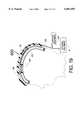
- the control moduleis to be placed in the cranium of the skull at a place where a significant volume of bone is removed.
- the probability of wire breakage due to repeated wire bendingis drastically reduced.
- the present inventionalso envisions the placement in the chest or abdomen of a control module if a large battery or a large volume electronics module dictates such a large size for the control module that it cannot be conveniently placed within the cranium.
- Such a thoracic or abdominal placement of a control modulewould require wires to be run through the neck.
- the present inventionalso envisions the utilization of an intracranial system for the treatment of certain diseases without placing wires through the neck.
- an alternative embodiment of the inventionenvisions the use of electrodes in or on the brain with an intracranial control module used in conjunction with a remote sensor/actuator device.
- blood pressurecould be sensed with a threshold of, let us say 150 mm Hg, and if that pressure was exceeded, a signal transmitted by electrical conduction through the body from the remote sensor/actuator device could be received at the control module and that would cause brain stimulation in such a way as to reduce the blood pressure.
- a signalcould be sent by electrical conduction through the body to a remote sensor/actuator device which could provide electrical stimulation to locally stimulate a nerve to reduce the perception of that pain.
- a remote actuatorcould be used to electrically stimulate one or both vagus nerves so as to stop the epileptic seizure from occurring.
- Such a remote devicecould be located in the trunk of the patient's body.
- Another important aspect of this inventionis that a comparatively simple surgical procedure can be used to place the control module just beneath the patient's scalp.
- a similar simple procedurecan be used to replace either the battery or both the battery and the electronics module. Specifically, if the hair on the scalp is shaved off at a site directly over where the control module is implanted, an incision can then be made in the scalp through which incision a depleted battery can be removed and replaced with a new battery, or a more advanced electronics module can replace a less capable or failed electronics module. The incision can then be closed, and when the hair grows back, the entire implanted system would be cosmetically undetectable. A good cosmetic appearance is very important for the patient's psychological well being.
- control moduleis optimally placed in either the left or right anterior quadrant of the cranium. Because the large sagital sinus vein runs along the anterior-posterior center line of the cranium, it is inadvisable to run epidural wires through that region, and furthermore, it would be inadvisable to place the control module directly over that major vein. Since movement of the jaw causes motions of the scalp relative to the cranium, it is advisable to run the connecting wires for electrodes that must be placed on the anterior portion of the brain in the epidural space as opposed to running them between the scalp and the cranium.
- the connecting wires for electrodes to be placed on a posterior portion of the brain's surfaceare best located beneath the scalp, then through burr holes in the cranium where they connect to any electrodes placed in a posterior position on the surface of the dura mater.
- most of the length of the connecting wires for electrodes located in the anterior portion of the brainwould be placed in the epidural space. In no case should epidural wires be passed through the anterior-posterior centerline of the brain where the large sagital sinus vein is located.
- An important operational aspect of the implanted systemis the use of an input-output coil formed from many turns of fine wire that is placed between the scalp and the cranium generally along the anterior-posterior center line of the head. All communication between the external equipment and the implanted system can be accomplished by magnetic induction through the hair and scalp of the patient. Examples of these signals are the readout of telemetry from the implanted system, or the changing of some operational parameter of the implanted system by means of a command from some piece of external equipment. Furthermore, such an input-output coil can be used to recharge a rechargeable battery that can be located inside the control module. Since the input-output coil can be placed on a posterior portion of the cranium, relative motion of the scalp and cranium should not be a problem in that region.
- the patientcan be provided with a cap to be worn on the head which cap includes a flexible coil that can communicate by magnetic induction using an alternating magnetic field with the implanted input-output coil.
- a capcould be placed on the patient in the doctor's office when the doctor wishes to read out stored telemetry or program one or more new parameters into the implanted system.
- the capcould be used by the patient at home for remote connection to the physicians workstation over telephone lines using a pair of modems, or the cap could be used to recharge a rechargeable battery located in the control module of the implanted system.
- a buzzerthat can be implanted just behind the ear on the outer or inner surface of the cranium or actually within a burr hole within the cranium. If a neurological event is detected, the buzzer can provide an acoustic output that is detectable by the patient's ear or the buzzer can provide an electrical "tickle" signal.
- the buzzercan be used to indicate to the patient that a neurological event such as an epileptic seizure is about to occur so that an appropriate action can be taken.
- a neurological eventsuch as an epileptic seizure is about to occur so that an appropriate action can be taken.
- the appropriate actions that could be taken by the patientis the application of an acoustic, visual or sensory input that could by themselves be a means for stopping a neurological event such as an epileptic seizure.
- the acoustic inputcould be by means of a sound producing, hearing aid shaped device that can emit an appropriate tone as to pitch and volume directly into the ear.
- the visual devicecould be from a light emitting diode in eyeglasses or a small flashlight type of device that emits a particular type of light at some appropriate flashing rate.
- a sensory inputcould be provided by, for example, an externally mounted electrical stimulator placed on the wrist to stimulate the median nerve or by a mechanical vibrator applied to the patient's skin.
- any such acoustic, visual or other sensory inputis actuated, either automatically or manually in response to the detection of a neurological event, literally billions of neurons are recruited within the brain. The activation of these neurons can be an effective means for stopping an epileptic seizure.
- An alternative embodiment of the present inventionenvisions the use of a control module located external to the patient's body connected to electrodes either external or internal to the patient's scalp. Such an externally located control module might be positioned behind the patient's ear like a hearing aid.
- Another object of this inventionis to provide increased reliability for neurological event detection by the use of cross-correlated signals from multiple electrodes with appropriate time delay(s) to increase the sensitivity and reliability for detection from a specific area of the brain.
- Still another object of this inventionis to exploit a spectral characteristic of the signals from multiple electrodes to optimize the detection of a neurological event.
- Still another object of this inventionis to use the detection of an EEG signal DC shift from one or more brain electrodes to identify the onset of a neurological event.
- Another objectis to detect the activity preceding the EEG signal DC shift from one or more brain electrodes to identify the onset of a neurological event.
- Still another objectis to use a detection scheme which looks for the combination of the activity preceding the EEG signal DC shift and the DC shift itself to identify the onset of a neurological event.
- Still another object of this inventionis to predispose the decision-making algorithm to allow false positives to cause a responsive stimulation but to disallow missing an actual event.
- Still another object of this inventionis to have the response to a neurological event be an electrical stimulation that is focused on a specific area of the brain by variably delaying the stimulation signal sent from each of several stimulation electrodes placed at different locations placed in close proximity to the brain or within the brain.
- Still another object of this inventionis to have the specific area of the brain onto which the response is focused be the area from which the event signal was detected.
- Still another object of this inventionis to record (and ultimately recover for analysis) the EEG signal(s) from one or more electrodes before, during and after a neurological event.
- Still another object of this inventionis to provide programmability for all-important operating parameters of the device.
- Still another object of this inventionis to provide recording of the certain functions of the device such as how many neurological events were detected and how many times the device responded to such detections.
- Still another object of this inventionis to use medication delivery as the response to a neurological event, either alone or in conjunction with electrical stimulation.
- Still another object of this inventionis to utilize implanted electronic circuitry which is adaptable to changing EEG input signals so as to provide self-adaptation for the detection and/or treatment of a neurological event.
- Still another object of this inventionis to have a system of electrodes connected by wires to a control module, the entire system being placed under the scalp and being essentially contained within the cranium.
- Still another object of this systemis to have essentially no flexure of interconnecting wires so as to enhance system reliability.
- Still another object of this inventionis to be able to replace a depleted battery within the system's control module by a comparatively simple and quick surgical procedure.
- Still another object of this inventionis to be able to replace an electronics module within the system's control module by a comparatively simple and quick surgical procedure.
- Still another object of this inventionis to be able to recharge the battery in the control module.
- Still another object of this inventionis to provide an externally situated patient's initiating device that can be used by the patient when he or she senses that a neurological event is about to occur in order to provide a response for causing the stopping of that neurological event or in order to initiate the recording of EEG signals from a pre-selected set of electrodes.
- Still another object of this inventionis to utilize a remotely located sensor/actuator device within the body to detect an abnormal physiological condition and send an electrical signal with or without wires to a control module within the cranium which then responds by an electrical signal delivered to the brain to treat the abnormal physiological condition.
- Still another object of this inventionis to utilize an intracranial system for sensing some abnormal physiological condition and then sending an electrical signal with or without wires to a remote sensor/actuator device that is remotely located within the body to carry out some treatment modality.
- Still another object of this inventionis to provide a buzzer which indicates to the patient that a neurological event has occurred.
- Still another object of this inventionis to provide acoustic, visual or other sensory inputs to the patient either automatically or manually following the detection of a neurological event so as to stop the neurological event.
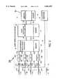
- FIG. 1is a top view of a human head showing the configuration of an implantable system for the treatment of neurological disorders as it would be situated in the human skull.
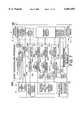
- FIG. 2is a block diagram of the implanted and external portions of the system.
- FIG. 3is a block diagram illustrating the event detection sub-system which utilizes digital signal processing techniques that can exploit either or both time and frequency domain information to accomplish event detection.
- FIG. 4is a flow chart pertinent to the processing activity carried on within the programmable digital signal processor which is part of the event detection sub-system.
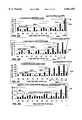
- FIG. 5Aillustrates the amplitude of the electrical signal received at FIFO memory 344A as a function of time.
- FIG. 5Billustrates the amplitude of the electrical signal received at FIFO memory 344B as a function of time.
- FIG. 5Cillustrates the amplitude of the electrical signal received at FIFO memory 344C as a function of time.
- FIG. 5Dillustrates the sum of the time delayed signal amplitudes showing also that the event detection threshold is exceeded at -20 milliseconds.
- FIG. 6illustrates a block diagram for an alternative algorithm for detection of a neurological event which uses the amplitude differences of signals from pairs of electrodes.
- FIG. 7is a flow chart of the event recording and processing which is carried on within the event processing microcomputer used for the second stage of an event detection sub-system.
- FIG. 8illustrates the recording of EEG and/or EEG spectrum signals by the central processor.
- FIG. 9shows a flow chart of the central processor function for: (1) receiving event detection information from the event detection sub-system; (2) sending delay and threshold parameters to the event processing microcomputer and digital signal processor; (3) storing event related data; (4) inducing responsive brain stimulation through the stimulation sub-system; and (5) communicating externally for physician data read out and system programming.
- FIG. 10is a block diagram of the stimulation sub-system as used to stimulate the brain responsive to a detected event.
- FIG. 11is a block diagram of the data communication sub-system and external data interface.
- FIG. 12is a block diagram of a hybrid analog/digital representation of the event detection sub-system using time domain information for event detection.
- FIG. 13is a block diagram of a hybrid analog/digital representation of the event detection sub-system using frequency domain information for event detection.
- FIG. 14is a block diagram of an implantable system that can respond to a detected neurological event by infusing medication into the patient's body.
- FIG. 15is a top view of a human head showing the arrangement of a multiplicity of electrodes connected by wires to a control module that is implanted within the cranium.
- FIG. 16is a side view of a human head showing the arrangement of one surface and one deep electrode connected by wires that pass through a hole in the cranium and connect to a control module that is implanted within the cranium.
- FIG. 17is a top view of a human head showing the arrangement of an implanted input-output flat wire coil connected by wires to a control module that is implanted within the cranium.
- FIG. 18is a side view of a human head showing the arrangement of the implanted input-output flat wire coil as it would be used with a patient's initiating device to trigger some operation of the implanted system.
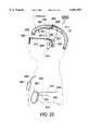
- FIG. 19is a side view of a human head showing the arrangement of the implanted input-output coil as it would be used with a cap and with the physician's external equipment to perform some interaction with the implanted system.
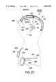
- FIG. 20is a top view of the shell of the control module.
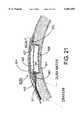
- FIG. 21is a cross section of the cranium showing a control module placed essentially within the cranium within a space where cranium bone has been removed.
- the cross section of the shell in FIG. 21is taken along the section plane 21--21 of FIG. 20.
- FIG. 22is a side view of the human head and torso showing an alternative embodiment of the present invention using a control module implanted within the chest.
- FIG. 23is a side view of the human head and torso showing an alternative embodiment of the present invention using a control module implanted between the scalp and the cranium, a remote sensor/actuator device located within the chest, and external devices for applying acoustic, visual, or other sensory input to the patient.
- FIG. 24is a side view of a human head showing alternative communication means between the external equipment and an implanted control module and also showing alternative locations for electrodes mounted in close proximity to the patient's brain.
- FIG. 25is a side view of the human head and torso showing an alternative embodiment of the present invention using a control module located external to the patient's body and a remote sensor/actuator device located within the chest, and external devices for applying acoustic, visual, or other sensory input to the patient.
- FIG. 26illustrates a block diagram for an alternative algorithm for detection of a neurological event which uses the DC shift in the EEG signals from one or more electrodes to identify the onset of a neurological event.
- FIG. 1illustrates the configuration of an implantable system 10 for the treatment of neurological disorders as it would be situated under the scalp of a human head 9 having a control module 20, electrodes 15A, 15B, 15C, 15N and 16 with wires 17A, 17B, 17C, 17N and 18 connected through the connector 8 to the control module 20.
- the control module 20is permanently implanted into the top of the skull in a location where the skull is fairly thick. It is also envisioned that the control module 20 could be located in the trunk of the patient's body like a heart pacemaker with the connecting wires being run under the patient's skin.
- the electrodes 15A, 15B, 15C, 15N and 16would be placed under the cranium and above the dura mater (i.e., placed epidurally) or placed deep into the brain.
- the connecting wires 17A, 17B, 17C, 17N and 18would be run from the control module 20 underneath the scalp and then be connected to the electrodes placed beneath the patient's cranium.
- FIG. 1shows only 4 active electrodes 15A, 15B, 15C, 15N with connecting wires 17A, 17B, 17C, 17N, more than 4active electrodes with connecting wires may be used with the present invention.
- the electrode 16(having a connecting wire 18) could be considered a common or indifferent electrode.
- the terminology “the electrodes 15A through 15N”is meant to include all electrodes 15A, 15B, 15C, . . . to 15N inclusive where N may be any integer between 1 and 200. Similar terminology using the words “through” or “to” for other groups of objects (i.e., wires 17A through 17N) will have a similar inclusive meaning.
- FIGS. 1 through 25 inclusivelines connecting boxes on block diagrams or on software flow charts will each be labeled with an element number. Lines without arrows between boxes and/or solid circles indicate a single wire.
- a physical connectionnamely a wire or group of wires (data bus) over which analog or digital signals may be sent.
- Data streamsinclude messages, analog or digital signals, commands, EEG information, and software downloads to change system operation and parameters.
- FIG. 2is a block diagram of the implantable system 10 and the external equipment 11.
- the wires 17A through 17N from the electrodes 15A through 15N, and the wire 18 from the common electrode 16,are shown connected to both the event detection sub-system 30 and the stimulation sub-system 40. It is also envisioned to use the case of the control module 20 of FIG. 1 as the common (or indifferent) electrode 16.
- the wires 17A through 17Ncarry EEG signals 21A through 21N from the electrodes 15A through 15N to the event detection sub-system 30.
- the electrodes 15A through 15Ncan be energized by the stimulation sub-system 40 via the wires 17A through 17N to electrically stimulate the patient's brain using the stimulation signals 412A through 412N respectively.
- the electrodes 15A through 15N and 16 shown hereare connected to both the event detection sub-system 30 and the stimulation sub-system 40, it is obvious that a separate set of electrodes and associated wires could be used with each sub-system. Furthermore, it is envisioned that any one, several or all of the electrodes 15A through 15N could be electrically connected (i.e., shorted) to the electrode 16 or to each other. This would be accomplished by appropriate switching circuitry in the stimulation sub-system 40.
- the event detection sub-system 30receives the EEG signals 21A through 21N (referenced to system ground 19 connected to the wire 18 from the common electrode 16) and processes them to identify neurological events such as an epileptic seizure or its precursor.
- a central processing system 50 with central processor 51 and memory 55acts to control and coordinate all functions of the implantable system 10.
- the interconnection 52is used to transmit programming parameters and instructions to the event detection sub-system 30 from the central processing system 50.
- the interconnection 53is used to transmit signals to the central processing system 50 identifying the detection of a neurological event by the event detection sub-system 30.
- the interconnection 53is also used to transmit EEG and other related data for storage in the memory 55.
- the central processor 51can command the stimulation sub-system 40 via the interconnection 54 to transmit electrical signals to any one or more of the electrodes 15A through 15N via the wires 17A through 17N. It is anticipated that, if appropriate electrical signals 412A to 412N inclusive are transmitted to certain locations in or near the brain, the normal progression of an epileptic seizure can be aborted. It may also be necessary for the stimulation sub-system 40 to temporarily disable the event detection sub-system 30 via the interconnection 29 when stimulation is imminent so that the stimulation signals are not inadvertently interpreted as a neurological event by the event detection system 30.
- a power supply 90provides power to each component of the system 10.
- Power supplies for comparable implantable devicessuch as heart pacemakers and heart defibrillators are well known in the art of implantable electronic devices.
- Such a power supplytypically utilizes a primary (non-rechargeable) storage battery with an associated d-c to d-c converter to obtain whatever voltages are required for the implantable system 10.
- the power supplycould use a rechargeable battery that is charged by means of a coil of wire in the control module 20 that receives energy by magnetic induction from an external coil that is placed outside the patient but in close proximity to the control module.
- the implanted coil of wirecould also be located remotely from control module 20 but joined to it by electrical wires. Such technology is well known from the rechargeable cardiac pacemaker.
- the same pair of coils of wirecould be used to provide power to the implanted system 10 when it is desired to read out stored telemetry or reprogram some portion of the implanted system 10.
- Data stored in the memory 55can be retrieved by the patient's physician by a wireless communication link 72 with the data communication sub-system 60 connected to the central processing system 50.
- An external data interface 70can be directly connected with an RS-232 type serial connection 74 to the physician's workstation 80.
- the serial connectionmay be via modems 85 and 750 and phone line 75 from the patient's home to the physician's workstation 80.
- the software in the computer section of the physician's work station 80allows the physician to read out a history of events detected including EEG information both before, during and after the event as well as specific information relating to the detection of the event such as the time evolving energy spectrum of the patient's EEG.
- the workstation 80also allows the physician to specify or alter the programmable parameters of the implantable system 10.
- a buzzer 95 connected to the central processor 51 via the link 92can be used to notify the patient that an event has occurred or that the implanted system 10 is not functioning properly.
- the buzzercould provide a mechanical vibration (typically an acoustic signal) or an electrical stimulation "tickle" either of which could be perceived by the patient.
- a mechanical vibrationtypically an acoustic signal
- an electrical stimulation "tickle"either of which could be perceived by the patient.
- a real time clock 91is used for timing and synchronizing various portions of the implanted system 10 and also to enable the system to provide the exact date and time corresponding to each neurological event that is detected by the implantable system 10 and recorded in memory.
- the interconnection 96is used to send data from the central processor 51 to the real time clock 91 in order to set the correct date and time in the clock 91.
- the various interconnections between sub-systemsmay be either analog or digital, single wire or multiple wires (a "data bus").
- the event detection sub-system 30continuously processes the EEG signals 21A through 21N carried by the wires 17A through 17N from the N electrodes 15A through 15N.
- the event detection sub-system 30notifies the central processor 51 via the link 53 that an event has occurred.
- the central processor 51then triggers the stimulation sub-system 40 via the link 54 to electrically stimulate the patient's brain (or electrically short some electrodes or release medication) in order to stop the neurological event using any one, several or all of the electrodes 15A through 15N.
- the stimulation sub-system 40also sends a signal via the link 29 to the event detection sub-system 30 to disable event detection during stimulation to avoid an undesired input into the event detection sub-system 30.
- the central processor system 50will store EEG signals and event related data received from the event detection sub-system 30 via the link 53 over a time from X minutes before the event to Y minutes after the event for later analysis by the patient's physician.
- the value of X and Ymay be set from as little as 0.1 minutes to as long as 30 minutes.
- the central processor S1may "buzz" to notify the patient that an event has occurred by sending a signal via the link 92 to the buzzer 95.
- FIG. 3is a block diagram illustrating an implementation of the event detection sub-system 30 using digital signal processing techniques.
- the event detection sub-system 30can use either or both, time and frequency domain information for event detection.
- the event detection sub-system 30receives the signals 21A through 21N from the wires 17A through 17N and processes them to identify the early stages of a neurological event such as an epileptic seizure.
- the signals 21A through 21Nare amplified by the amplifiers 32A through 32N respectively, to produce the amplified EEG signals 22A through 22N.
- the amplifiers 32A through 32Ncan also provide low pass and/or high pass filtering to remove unwanted noise.
- Each amplifier 32A through 32Ncan be disabled by a signal placed on interconnection 29 from the stimulation sub-system 40 during brain stimulation so as to prevent overloading the amplifiers or creating an undesired input signal into the event detection sub-system 30.
- the amplified EEG signals 22A through 22Nare then digitized by the analog-to-digital converters 33A through 33N producing the digitized EEG signals 23A through 23N which are processed by the programmable digital signal processor 34 with associated memory 35 to enhance the signal-to-noise ratio for the detection of neurological events.
- Processed signals 24are then passed to the event processing microcomputer 36 with associated memory 37 for analysis with the goal of achieving event detection.
- the event processing microcomputer 36identifies an event, it produces a detection signal which it sends along with stored EEG and EEG energy spectral data streams to the central processor 51 through the interconnection 53.
- the central processor 51can pass specific program parameters and revised programming instructions to the event processing microcomputer 36 via the interconnection 52.
- the event processing microcomputer 36can also pass any appropriate program parameters and revised programming instructions received from the central processor 51 on to the programmable digital signal processor 34 via the interconnection 25.
- This schemeprovides patient-specific optimization of event detection algorithm(s). For example the program might look at signal amplitude differences between certain electrodes, or alternately, event detection might be based on analysis of a signal created by adding the signals (possibly with varying time delays) derived from a specific subset of the electrodes.
- the programmable digital signal processor 34might be programmed to perform both digital signal processing and event processing thus not requiring a separate event processing microcomputer 36.
- the event processing microcomputer 36 and the central processor 51may be the same microcomputer having separate subroutines in software for each function.
- the amplifiers 32A through 32N, the analog-to-digital converters 33A through 33N and the programmable digital signal processor 34each separately and collectively constitute a signal conditioning means for processing the EEG signals 21A through 21N.
- the event processing microcomputer 36provides event detection means for the detection of a neurological event.
- Integrated circuit amplifiersanalog-to digital converters, digital signal processors (DSPs), digital memory and microcomputers and the techniques to interconnect and program them are well known in the art. Custom VLSI or hybrid circuits could be developed that would combine certain functions.
- FIG. 4is a flow chart pertinent to the processing activity 340 carried on within the programmable, digital signal processor 34 of the event detection sub-system 30.
- the digitized EEG signals 23A through 23Nare first processed by the step of removing any d-c bias by the subroutines 341A through 341N producing digital signals 351A through 351N which are then processed by the automatic gain control (AGC) subroutines 342A through 342N to produce the AGC EEG signals 352A through 352N.
- AGCautomatic gain control
- the step of AGC at this stage of the processingwill allow the use of a constant threshold for event identification at a later stage.
- the AGC time constantis among the programmable parameters that can be programmed in the DSP program instructions 348 that are passed via the interconnection 25 from the event processing microcomputer 36.
- AGC algorithmswhich adjust the output gain based on time averaged energy are well known in the art and can be implemented by an experienced DSP programmer. It is also envisioned that the amplifiers 32A through 32N of FIG. 3 might be analog AGC amplifiers so that a DSP AGC algorithm would be unnecessary.
- AGCis an example of a self-adaptive algorithm used by the event detection sub-system 30.
- the process of removing d-c bias by the subroutines 341A through 341 Nrequires the real time measurement of the d-c component of the EEG signals 23A through 23N. Recent studies have indicated that there is a significant shift in the d-c component of the EEG signal just before the onset of an epileptic seizure.
- the subroutines 341A through 341Ncould, therefore, also act as d-c shift detectors for identifying the onset of an epileptic seizure.
- the processed EEG signals 352A through 352Nare continuously passed via the interconnections 24 to the event processing microcomputer 36 so that they may be stored for later physician analysis if a neurological event occurs.
- the processed EEG signals 352A through 352Nare also processed further by additional signal conditioning steps to enhance event identification. These steps involve first squaring the signals 352A through 352N using the squaring subroutines 343A through 343N to produce the squared EEG signals 353A through 353N.
- the squared EEG signals 353A through 353Nare fed into the First-In-First-Out (FIFO) buffers 344A through 344N where between 1 and 100 milliseconds of data can be stored.
- FIFOFirst-In-First-Out
- a preferred embodiment of the digital signal processing algorithm 340 for event detectionis based on the principle that the signals arriving at the electrodes 15A through 15N (shown in FIG. 2) from an epileptic focus will always do so with essentially the same time delay for each electrode. Or stated another way, the propagation time required for a signal to travel from the epileptic focus to an electrode will be consistently as follows: t 1 milliseconds for a electrode 15A, t 2 milliseconds for electrode 15B, t 3 milliseconds for electrode 15C, etc., where t 1 , t 2 , t 3 . . .
- the FIFOs 344A through 344Nare nothing more than a digital equivalent of a delay line where the sum with delay algorithm 345 can elect to sample the squared EEG signals 353A through 353N with each delayed appropriately to create the time synchronized EEG signals 354A through 354N which are summed by the sum with delay algorithm 345.
- the sum with delay algorithm 345will produce the sum of time synchronized squared signals 355. EEG signals originating from parts of the brain away from the focus will not be synchronized by the algorithm 345 whose time delays are set to synchronize EEG signals originating at the focus. Thus the amplitude of the sum of time synchronized squared signals 355 will be much larger for EEG signals originating at the focus.
- the delays for each of the FIFO buffersare programmed through the DSP program instructions 348.
- the settings for FIFO time delayswould be derived from analysis of recorded EEG signals during events from a patient having the same electrode configuration to be used for event detection.
- Interconnection 25is the interconnection over which the programming instructions 348 are provided by the event processing microcomputer 36 to set the time delay parameters for the FIFO buffers.
- the signal 355can be sent to the event processing microcomputer 36 for time domain event detection.
- the signal 355can also be transformed into the frequency domain by the transform algorithm 346, which will produce a frequency spectrum that can change with time having frequency band signals 356-1, 356-2, 356-3, 356-4 through 356-M which are the time evolving signals corresponding to a total of M frequency bands (band 1 through band M).
- the frequency band signals 356-1 through 356-Mare digital data streams, each representing the energy of the signal 355 in the corresponding frequency band (band 1 through band M).
- An example of such frequency bandsis as follows: (a) band 1:1 to 2 Hz; (b) band 2:2 to 4 Hz; (c) band 3:4 to 8 Hz; etc.
- the specific division of the bandsis programmable through the DSP programming instructions 348 and may be derived for each patient from analysis of recorded EEG information.
- the frequency band signals 356-1 through 356-Mare sent to the event processing microcomputer 36 for the purpose of event detection.
- FIGS. 3 and 4illustrate one embodiment of a multiple step signal conditioning means for the EEG signals 21A through 21N.
- the specific steps used in this embodimentare amplification, analog-to-digital conversion, adjustment of d-c offset, AGC, squaring, time delaying, summing and frequency transformation.
- the ability to program the programmable digital signal processor 34 to implement any combination of these or other steps in any order to enhance event detection for each patientis an important aspect of the event detection sub-system 30.
- FIGS. 5A, 5B and 5Cshow the signal traces for a 3 electrode implementation of the present invention with the squared EEG signals 353A, 353B and 353C stored in the FIFOs 344A, 344B and 344C respectively.
- the FIFOs 344A, 344B and 344Cstore 100 milliseconds of data consisting of 20 samples each, with each sample being the average value for a period of 5 milliseconds of the squared EEG signals 353A, 353B and 353C.
- the last data placed in the FIFOs 344A, 344B, and 344Ccorrespond to time equals zero, and are the most recent samples of the squared EEG signals 353A, 353B and 353C.
- the relative delays between EEG signals from an epileptic focus arriving at electrodes 15A, 15B and 15Cwould be calculated.
- the electrode 15A from which the data in FIFO 344A originatesis the last to receive the EEG signal from such an event.
- the time delay parameter 358A for the electrode 15Ais therefore set to 0.
- electrode 15B which is the source of data for FIFO 344Bis known to receive an event signal 15 ms before electrode 15A thus the time delay parameter 358B for electrode 15B is set to 15 ms.
- the specific samples 354A, 354B and 354Care fed into the sum with delay algorithm 345.
- the sum with delay algorithm 345adds these specific FIFO samples together to produce the signal 355 as shown in FIGS. 4 and 5D.
- FIG. 5Dshows the current sample of the signal 355 and the last 100 milliseconds of the signal 355 created by the sum with delay algorithm 345.
- a simple means to detect, a neurological event using the sum with delay algorithm 345 with resulting signal 355is to compare the signal 355 with a fixed event detection threshold 369 as shown in FIG. 5D.
- the threshold 369is exceeded at times 0, -10 ms and -20 ms.
- This methodologycan be an effective means for event detection when used in conjunction with the automatic gain control algorithms 342A, 342B and 342C as shown in FIG. 4.
- the automatic gain controlhas the effect which is seen in FIGS. 5A through 5C of keeping the samples of the squared EEG signals below the AGC limits 362A, 362B and 362C which limits are programmed into the automatic gain control algorithms 342A, 342B and 342C shown in FIG. 4.
- the AGC subroutines 342A, 342B and 342Cmight adjust the amplitude of the EEG signals 352A through 352N based on the average energy detected over a period of several minutes so that a rapidly changing signal such as that from a neurological event will not be affected.
- the delay parameters 358A, 358B and 358Cmay be self-adaptive so that when an event is detected, post-analysis by the digital signal processor 34 using the data stored in the FIFOs 344A, 344B and 344C can determine if adjusting the delays 358B and 358C plus or minus in time would increase or decrease the sum of the time synchronized squared EEG signals 355. If the signal 355 increases by a shift of the time delay 358B or 358C, then the delay parameters 358B and 358C could be automatically changed to increase the sensitivity for future event detection.
- This example of the capability to modify it's own operating parametersis an example of self-adaptation of the programmable digital signal processor 34.
- other programmable components of the system 10 of FIG. 2 other than the event detection sub-system 30may be self-adaptive to be capable of optimizing system operability without external commands.
- FIGS. 5A-5Dshow the signals relating to an implementation of the present invention using 3 signal electrodes, the algorithms described can be applied to any set of 2 or more signal electrodes.
- the electrodesinstead of delaying the signals from each electrode to provide time synchronization, the electrodes might be placed at positions where the time delays from an epileptic focus to each electrode could be the same. Furthermore, it is envisioned that instead of squaring the value of the EEG signal amplitude, which is done to eliminate a zero average over a certain period of time, the same objective could be accomplished by rectification of the EEG signal.
- FIG. 6shows an embodiment of the present invention in which the digital signal processor processing 440 based on DSP program instructions 448 takes the digitized EEG signals 23A, 23B, 23C and 23D from four brain electrodes 15A, 15B, 15C and 15D and creates the difference signal 424 from signals 23A and 23B using the subtraction algorithm 434, and the difference signal 425 from signals 23C and 23D using the subtraction algorithm 435.
- the difference signals 424 and 425can then be multiplied by weighting factor algorithms 436 and 437 to adjust for difference in signal level for events arriving at each pair of electrodes.
- the resulting weighted differential EEG signals 426 and 427are summed by the algorithm 438 to create the summed differential EEG signal 428.
- the summed differential EEG signal 428can then be transformed into a set of frequency band signals 456-1 through 456-M by the algorithm 446 as previously described with respect to the digital signal processing 340 shown in FIG. 4.
- FIG. 6will work best when the electrode pairs 15A-15B and 15C-15D are located in positions that will cause the EEG signal differences 424 and 425 to be synchronized in time for EEG signals originating at the focus of a neurological event. It is also envisioned that a programmable delay adjustment, as described for FIG. 4, could be implemented here if the time delays for EEG signal differences 424 and 425 from a neurological event are not the same.
- the summed differential EEG signal 428, the difference EEG signals 424 and 425, and the frequency band signals 456-1 through 456-Mcan be sent via interconnection 24 to the event processing microcomputer 36 for storage.
- the input stagecould use any one or more pairs of brain electrodes with no single common electrode.
- the processing 340 of FIG. 4 and 440 of FIG. 6are examples of two different implementations of multiple step signal conditioning programs which can be run within the programmable digital signal processor 34 of FIGS. 2 and 3.
- FIG. 7shows the software flow chart for event recording and processing 360 of the event processing microcomputer 36 used for the second stage of the event detection sub-system 30 shown in FIGS. 2 and 3.
- event recording and processing 360represents the algorithms and subroutines in software used by the event processing microcomputer 36 (hardware) as the event detection means and also to record relevant EEG and spectral band data.
- a primary objective of event recording and processing 360 softwareis to make possible the recording of AGC modified EEG signals 352A through 352N inclusive and the frequency band signals 356-1 to 356-M inclusive by the central processing system 50.
- FIG. 8indicates that the central processing system 50 is capable of recording EEG and frequency band data for "X" minutes before a neurological event is detected and "Y" minutes after the neurological event is detected.
- the event recording and processing 360 of FIG. 7is used to facilitate this data recording capability.
- the EEG signals 352A through 352N(also see FIG. 4) are stored in data FIFO memories 363A through 363N. If an event is detected, the FIFOs 363A through 363N can be read by the central processor 51 via the link 53 to retrieve the stored EEG data streams 373A through 373N for a time "X" minutes before the event.
- the central processor 51can also read the data FIFOs 363A through 363N in real time after detection of a neurological event for a period of "Y" minutes.
- the data FIFOs 363A through 363Ncould be used to store and then read out "Y" minutes of data stored after the event is detected.
- the goal of retrieving "X" minutes of pre-event detection data and "Y" minutes of post-event detection datacan be achieved.
- the central processing system 50may be programmed to record EEG data from a sub-set of the electrodes 15A through 15N (see FIG. 2). All data stored by the central processing system 50 can be retrieved by the patient's doctor for analysis with the goal of improving the response of the system 10 so as to more reliably stop a neurological event.
- FIG. 7also shows two different schemes for detecting an event. If the amplitude of the sum of the time synchronized squared EEG signals 355 exceeds the event detection threshold 369 as shown in
- FIG. 5D(using threshold detector algorithm 368 of FIG. 7), the algorithm 368 sends a positive event detected message 358 to the event density counter/detector algorithm 371.
- the event density counter/detector algorithm 371determines if there have been enough events in the most recent time period "T" to notify the central processor 51 with the event identified message 372 indicating that an event has really occurred.
- a typical time period "T”would be approximately 2 seconds but could be in the range from 1/2 to 100 seconds.
- the event density counter/detector algorithm 371will reduce the number of false positive event identifications by eliminating short uncorrelated EEG bursts.
- the system for detecting a neurological event based on the threshold detector 368would involve processing data for the entire frequency spectrum of the sum of the time synchronized and squared EEG signals 355.
- the signal 355can be transformed into a set of frequency band signals 356-1 through 356-M inclusive each of which signals is of limited bandwidth as compared with the broadband signal 355.
- Each of the frequency band signals 356-1 through 356-M of FIG. 7can be analyzed by a threshold detector algorithm 367-1 through 367-M respectively in a manner exactly analogous to the threshold detector algorithm 368 used to detect events from the broadband signal 355.
- each of the set of threshold detector algorithms 367-1 through 367-Mcan send a positive event detected signal 357-1 through 357-M to a corresponding frequency band event density counter/detector 369-1 through 369-M when the amplitude of the frequency band signal 356-1 through 356-M exceeds a preset threshold level.
- the frequency band event density counter/detectors 369-1 through 369-Mwill, analogous to the event density counter/detector 371, determine if there are a sufficient number of events per time period "T" in any of the bands 1 through M to send an event identified message 359-1 through 359-M to the central processor 51 indicating that a neurological event has occurred.
- each of the M frequency band signals 356-1 through 356-Mis stored in FIFO memories 366-1 through 366-M, so that if an event is detected, the FIFOs can be read by the central processing system 50 via the link 53 to retrieve the frequency band data streams 376-1 through 376-M for a time "X" before event detection until some time "Y” after event detection.
- FIG. 8illustrates this concept for data storage.
- Constructing computer code to store and retrieve sampled digital signals from FIFO memoryis well known in the art of software design. Comparing an input signal amplitude against a preset threshold, determining the number of counts per unit time and comparing the counts per unit time against a preset number of counts per unit time are also well known in the art of software design.
- the software which is the digital signal processor processing 340is run by the programmable digital signal processor 34 according to the DSP program instructions 348.
- the software for event recording and processing 360is run by the event processing microcomputer 36 of FIG. 4 according to the program instructions for DSP and event processing 375.
- the programming instructions for DSP and event processing 375serves as a pass through for the DSP program instructions 348 of
- the program instructions for DSP and event processing 375are received by the event processing microcomputer 36 (using the software for event recording and processing 360) from the central processor 51 via the interconnection 52.
- the DSP program instructions 348are received over interconnection 25 by the digital signal processor 34 from the program instructions for DSP processing and event processing 375 of FIG. 7.
- the thresholds to be used for detection by the threshold detector algorithms 368 and 367-1 through 367-M and the required event densities for event identification by the event density counter/detector algorithms 371 and 369-1 through 369-Mwill typically be programmed to minimize the chance of missing a "real" neurological event even though this could result in the occasional false positive identification of an event. This bias toward allowing false positives might typically be set to produce from 1/2 to 5 times as many false positives as "real" events.
- the software for event recording and processing 360might not require a separate microcomputer but could operate either as a set of subroutines in the central processor 51 or a set of subroutines in the programmable digital signal processor 34.
- event recording and processing software 360could be programmed to provide an event detection means based on detecting specific aspects of the waveform of either time or frequency domain outputs of the signal conditioning by the digital signal processor 36. Such aspects of the waveform could include pulse width, first derivative or waveform shape.
- FIG. 9shows a flow chart of the software for central processor processing 510 as run by the central processor 51 of FIG. 2.
- the central processor 51receives event detection messages 372 and 359-1 through 359-M, EEG data streams 373A through 373N and the frequency band data streams 376-1 through 376-M from the event processing microcomputer 36.
- the central processor 51 of FIG. 2also sends and receives data to and from the data communication sub-system 60 via interconnections 56 and 57.
- the processing 510processes these messages, signals, and data streams.
- Algorithm 514receives the event detection messages 372 and 359-1 through 359-M provided by the event processing microcomputer 36 via the link 53.
- the algorithm 514calls the subroutine 512.
- the calling of the subroutine 512 by the algorithm 514is indicated by the element 515.
- the subroutine 512reads and saves to the central processor's memory 55 via the link 518, the last X minutes of stored EEG data streams 373A through 373N and frequency band data streams 376-1 through 376-M from the event processing microcomputer 36.
- the algorithm 512will continue to read and save to the central processor's memory 55, the next "Y" minutes of EEG data streams 373A through 373N and frequency band data streams 376-1 through 376-M from the event processing microcomputer 36. As seen in FIG. 8, these data streams may include a blank period during stimulation followed by data which can be analyzed to determine the efficacy of the treatment.
- the algorithm 514also causes a signal 511 to be sent to the stimulation sub-system 40 via the link 54 to cause the stimulation sub-system 40 to respond as programmed to stop the neurological event.
- Values for X and Ywill typically be several minutes for X and as much as a half-hour for Y.
- the memory 55must be large enough for at least one event and could be large enough to hold 10 or more events.
- the values X and Y like other parametersare programmable and adaptable to the needs of each particular patient.
- the I/O subroutine 517receives physician commands from the data communication sub-system 60 via the link 56 and, in turn, reads and sends back via the link 57 the data stream 519 containing the event related data previously stored in the memory 55 by the algorithm 512. These data are transmitted to the external equipment 11 by the data communication sub-system 60 via the wireless link 72 as shown in FIGS. 2 and 11.
- the I/O subroutine 517also plays a key role in the downloading of software programs and parameters 59 to the programmable sub-systems of the implantable system 10 of FIG. 2. These programmable sub-systems include the event detection sub-system 30, the central processing system 50 and the stimulation sub-system 40.
- the programmable components of the event detection sub-system 30are the programmable digital signal processor 34 and the event processing microcomputer 36 shown in FIG. 3.
- the programming instructions and parameters 59 for the programmable sub-systems 30, 40 and 50are downloaded through the I/O subroutine 517 by the programming and parameters downloading subroutine 516 of the central processor processing 510.
- the subroutine 516stores the instructions and parameters 59 and downloads the program instructions for DSP and event processing 375 (also see FIG.
- the subroutine 516also downloads the stimulation sub-system instructions and parameters 592 via the link 54 to the stimulation sub-system 40.
- the subroutine 516also updates the memory 55 with the programming instructions and parameters 594 for the central processor processing 510.
- Programmable microprocessors or self-contained microcomputerssuch as the Intel 8048 and 8051, which contain read only memory for basic programs and random access memory for data storage and/or program storage, can be used to implement the central processor processing 510 as previously described. It is also envisioned that a custom VLSI chip involving microprocessor, signaling and memory modules could be produced specifically for this application. All of the previously described algorithms to store data, send notification signals and messages and make decisions based on input data are straightforward for a software programmer to implement based on the current state of the art.
- EEG storagefor a 4 electrode system using 8 bits (one byte) per sample at a sampling rate of 250 samples per second (required for frequencies up to 125 Hz) will require 60,000 bytes per minute of data storage. Having 100 minutes of storage would require only 6 megabytes, which is readily achievable using current memory chip technology. Thus if both X and Y were each 1 minute, then a total of 50 neurological events could be stored in the 6 megabyte memory.
- non-volatile memorysuch as “flash memory” could be used to conserve power.
- FIG. 10illustrates the stimulation sub-system 40 including its interconnections to other sub-systems.
- the stimulation sub-system 40is used to stimulate the brain, responsive to a detected event.
- the preferred embodiment of the stimulation sub-system 40comprises a delay processing microcomputer 420 and N signal generators 422A through 422N attached to the electrodes 15A through 15N by the wires 17A through 17N.
- the event detection signal 511 from the central processor 51is received by the delay processing microcomputer 420 which first sends a signal via the link 29 to the event detection sub-system 30 to shut down event detection during stimulation.
- the delay processing microcomputer 420will then feed stimulation command signals 410A through 410N to the signal generators 422A through 422N for a specific pre-programmed time period.
- the stimulation command signals 410A through 410Nmay be simultaneous or may have a relative delay with respect to each other. These delays can be downloaded by the instruction and parameter download 592 from the central processor 51 via the link 54. It may be desirable that the delays be adjusted so that the stimulation signals 412A through 412N from the signal generators 422A through 422N reach the neurological event focus in the brain at the same time and in-phase. This could enhance performance of the stimulation sub-system 40 in turning off a neurological event. Alternately, experience may indicate that certain signals being out of phase when they arrive at the neurological event focus may be particularly efficacious in aborting a neurological event.
- the stimulation command signals 410A through 410Ncan be used to control the amplitude, waveform, frequency, phase and time duration of the signal generators' output signals.
- the typical stimulation signals 412A through 412N generated by the signal generators 422A through 422Nshould be biphasic (that is with equal energy positive and negative of ground) with a typical frequency of between 30 and 200 Hz, although frequencies of between 0.1 and 1000 Hz may be effective. It is also envisioned that pure d-c voltages might be used, although they are less desirable. If frequencies above 30 Hz are used, the signal generators could be capacitively coupled to the wires 17A through 17N.
- the typical width of the biphasic pulseshould be between 250 and 500 microseconds, although pulse widths of 10 microseconds to 10 seconds may be effective for a particular patient. Typical voltages applied may be between 1 millivolt and 10 volts rms. The stimulation would typically be turned on for several seconds although times as short as a 1 millisecond or as long as 30 minutes may be used.
- Biphasic voltage generation circuitsare well known in the art of circuit design and need not be diagrammed here. Similarly, the code to have the delay processing microcomputer 420 provide different command parameters to the signal generators 422A through 422N is easily accomplished using well known programming techniques.
- the delay processing microcomputer 420is shown here as a separate unit, it may be practical to have the central processor 51 or the event detection microcomputer 36 of FIG. 3 provide the required processing. Consolidating many of the processing functions within a single processor is practical with the system 10 of FIG. 2 as the real time demands on any one system typically occurs when the others are not extremely busy. For example, during processing to identify an event, there is no need for data I/O, EEG storage or stimulation. When an event is detected and there is a need for EEG storage and stimulation, there is reduced need for event detection processing.
- the stimulation sub-system 40could operate with only one electrode such as a single electrode centrally located at an epileptic focus, or a deep electrode implanted in the thalmus or the hippocampus of the brain. If this were the case, the delay processing microcomputer 420 would not be needed, and only a single signal generator circuit would be required.
- a single electrodecentrally located at an epileptic focus
- a deep electrodeimplanted in the thalmus or the hippocampus of the brain.
- FIG. 11shows the block diagram of the data communication sub-system 60 and the external data interface 70 including interconnections to the central processor 51 and the physician's work-station 80.
- the antenna 730 of the external data interfaceis placed near the antenna 630 of the data communication sub-system 60.
- the workstation 80is then connected by the cable 74 to an RS-232 serial data interface circuit 740 of the external data interface 70.
- the RS-232 serial data interface circuit 740connects to the RF transmitter 720 and RF receiver 710 through the serial connections 722 and 712, respectively.
- the workstation 80can be connected to the RS-232 serial data interface over a dial-up connection 75 using the modems 750 and 85.
- wireless signals 72can sent to and from the RF transmitter/receiver pair 610 and 620 of the data communication sub-system 60 and the RF transmitter/receiver pair 710 and 720 of the external data interface 70.
- the wireless signals 72are used to command software updates via the link 612 through the serial-to-parallel data converter 614 and the link 56 to the central processor 51.
- the wireless signals 72are also used to send stored data back through the link 57 through the parallel-to-serial data converter 624 through the link 622 to the RF transmitter 620.
- RF transceiver circuitry and antennas similar to thisare used in data communication with heart pacemakers and defibrillators, and therefore, this technology is well known in the art of implantable programmable devices.
- RS-232 interfaces, serial to parallel and parallel to serial conversion circuits,are also well known.
- FIG. 12is a block diagram of a hybrid analog/digital embodiment of an event detection sub-system 130 that uses time domain information for event detection.
- analog circuitry 139is used to process and detect possible neurological events
- digital logic circuitry 138is used to check if the density of possible events is sufficient to declare a "real" event.
- the incoming EEG signals 21A through 21N on wires 17A through 17Nare amplified by the amplifiers 131A through 131N which may also provide band-pass or low-pass filtering and/or AGC of the signals 21A through 21N resulting in the amplified signals 121A through 121N which are then squared by the squarer circuits 132A through 132N resulting in the squared signals 122A through 122N.
- the squared signals 122A through 122Nare then processed by a series of analog delay line circuits 133A through 133N to create the squared and time synchronized EEG signals 123A through 123N, which are subsequently added together by the summing circuit 135.
- the resulting summed time synchronized signal 125is then fed into a threshold detection circuit 136 which will output a digital pulse 126 whenever the summed time synchronized signal 125 exceeds a pre-set threshold.
- the digital pulses 126 collected over timeare then processed by the digital logic circuit 138 to determine if the event is real or not.
- the delay parameters 124A through 124Nare input to the delay lines 133A through 133N from the central processor 151 and can be pre-set for a particular patient. Setting the values for these time delays could be based on measured delays of EEG signals received from an epileptic focus during diagnostic testing of the patient using the implanted system 10 of FIG. 2.
- a signal 129is sent from the stimulation sub-system 40 to shut down the amplifiers 131A through 131N to avoid amplifier overload or mistakenly identifying a stimulation signal as a neurological event signal.
- Analog integrated circuits to multiply or sum analog signalsare commercially available. Integrated circuit bucket brigade analog delay lines are also commercially available. It is also envisioned that a hybrid circuit containing multipliers, summers and delay lines could be produced to miniaturize the system 130.
- a standard comparator circuitalso available as an integrated circuit, can be used as the threshold detector 136 to compare the signal 125 with a pre-set threshold. If the threshold is exceeded, then a pulse is sent via the connection 126 from the threshold detector circuit 136 to the event counter 141 of the digital logic 138.
- the digital logic 138which counts the number of event pulses per second emitted by the threshold detector 136, can be implemented using a simple programmable microcomputer similar to that described for event recording and processing 360 shown in FIG. 7, or it can be implemented by a collection of standard digital logic and counting circuitry. Such a set of circuitry could use a counter 141 to count the possible event pulses 126 generated by the threshold detector 136. An event detected pulse 128 would be emitted by the counter 141 only when it overflows.
- the counter 141is reset once a second by a reset pulse 147 from an OR gate 146 which has been sent a pulse 144 from the clock 142, then only if the counter 141 overflows in the one second time period between reset pulses 147 will the event detected pulse 128 be generated.
- Certain available counter chipscan be reset to a preset number rather than 0.
- the event counter 141could be implemented with such a counter chip so that a reset signal will cause the counter to reset to a preset number 148 that would be set via the connection 145 from the central processor 151.
- an 8 bit counter(which counts up to the number 256) could be set to overflow when the number of pulses counted by the counter 141 causes it to count from the downloaded preset number 148 to the number two hundred and fifty-six in less than one second.
- times of less than 1 second or more than 1 secondcan also be used for the time between the pulses 144 from the reset clock 142.
- the event detected pulse 128is also used to reset both the clock 142 and the event counter 141.
- An OR gate 146will allow the event counter 141 to be reset by either the pulse 144 from the clock 142 or the event detected pulse 128.
- the processing by the central processor 151would be analogous to that shown in FIG. 9.
- the specific threshold to be used for detection by the threshold detector 136 and the preset 148 for the event counter 141will typically be set to minimize the chance of missing a "real" event even though this will result in occasional false positive identification of an event.
- FIG. 13is a block diagram of a hybrid analog/digital representation of still another embodiment of the event detection sub-system 230 using frequency domain information for event detection.
- analog circuitry 239is used to process and detect possible events in each of M frequency bands.
- Digital logic circuitry 238is used to check if the density of possible events is sufficient to declare a "real" event.
- the front end (up through and including the sum 135) of the analog circuitry 239 of the sub-system 230is identical to the front end of the analog circuitry 139 of FIG. 12.
- the incoming EEG signals 21A through 21N on wires 17A through 17Nare amplified by the amplifiers 131A through 131N.
- These amplifiers 131A through 131N(which may also provide band-pass or low-pass filtering of the signals 21A through 21N) produce the amplified signals 121A through 121N.
- the amplified signals 121A through 121Nare then squared by the squarer circuits 132A through 132N resulting in the squared signals 122A through 122N.
- the squared signals 122A through 122Nare then processed by a series of analog delay line circuits 133A through 133N to create the squared and time synchronized EEG signals 123A through 123N, which are subsequently added together by the summing circuit 135.
- the resulting summed time synchronized signal 125is fed to a set of analog band-pass filters 266-1 through 266-M for the M frequency bands.
- the resulting band signals 256-1 through 256-Mare examined by the threshold detectors 267-1 through 267-M analogous to the threshold detector 136 of FIG. 12.
- Each of the threshold detectors (267-1 through 267-M)will generate a corresponding pulse (257-1 through 257-M) when a preset threshold is exceeded analogous to the pulse 126 generated by the threshold detector 136 of FIG. 12.
- the pulses 257-1 through 257-Mare fed into the event density counter/detectors 268-1 through 268-M each identical to the digital logic circuit 138 of FIG. 12.
- the event density counter/detectors 268-1 through 268-Mwill feed the detected frequency band event pulses 258-1 through 258-M to the central processor 251.
- the central processor 251processes events from event density counter/detectors in a similar manner to the central processor 151 of FIG. 12. The main differences are that the counter presets 259-1 through 259-M may be different for each of the bands as required to optimize sensitivity. During responsive brain stimulation, a signal 129 is sent from the stimulation sub-system 40 to shut down the amplifiers 131A through 131N to avoid amplifier overload or mistakenly identify a stimulation signal as an event signal. The processing by the central processor 251 would be analogous to that shown in FIG. 9.
- FIG. 14is a diagram of an implantable system 910 which can respond to a detected neurological event by infusing medication from an implantable medication system 91 into the patient's body through the hollow catheter 93.
- the system 910is identical to the system 10 of FIG. 2 except that the programmable drug delivery sub-system 91 replaces the stimulation sub-system 40 of FIG. 2 as the sub-system which provides the response to an neurological event detected by the event detection sub-system 30.
- the signal indicating that an event has been detected and the programming instructions for the implantable drug delivery system 91are transmitted via the link 96 from the central processor 51.
- CSFcerebrospinal fluid
- the event detection sub-system 30continuously processes the EEG signals 21A through 21N carried by the wires 17A through 17N from the N electrodes 15A through 15N.
- the event detection sub-system 30notifies the central processor 51 via the link 53 that an event has occurred.
- the central processor 51signals the drug delivery system 91 via the link 96 to infuse medication through the catheter 93 into the patient's body as a means for stopping a neurological event.
- the drug delivery system 91delivers pre-programmed drug infusion to the desired site.
- the central processor 51will store EEG and event related data from X minutes before the event to Y minutes after the event for later analysis by the patient's physician.
- the central processor 51may initiate a "buzz" to notify the patient that an event has occurred by sending a signal via the link 92 to the buzzer 95.
- an externally worn system with implanted electrodescould function adequately and would allow a plug-in interface to the data communication sub-system 60 and simple battery replacement. It is also envisioned that the techniques described above would work with an external device with electrodes attached to the outside of the head. External devices would have great merit in determining if an implantable system would work well enough to be warranted. An external version with implanted electrodes could be used to record EEG signals from neurological events to calculate the optimal programming algorithms and parameters to be used by a permanently implanted system using the same set of electrodes.
- EEG recording capabilities of the present inventioncould be used without the event detection and stimulation components to store patient EEG activity for diagnostic purposes.
- FIG. 15shows a top view of an intracranial system 600 consisting of brain surface electrodes 601, 602, 603, 604, 605 and 606 connected by wires 611, 612, 613, 614, 615 and 616 respectively which provide an electrical conducting means to join the electrodes 601 through 606 to a control module 620.
- a control module 620the proximal end of each of the wires 611 through 616 is connected to the control module 620, and the distal end of each of the wires 611 through 616 is connected to an electrode.
- these surface electrodes 601-606are placed between the bottom of the cranium (i.e., inside the skull) and the top of the dura mater that surrounds the brain. Thus this is an epidural placement of the surface electrodes.
- six surface electrodesare shown in FIG. 15, it is envisioned that as many as 12 or more active electrodes could be usefully implanted.
- the metal case of the control module 620could serve as a common or indifferent electrode which also could be considered to be at ground potential.
- the control modulemight utilize a case which is non-conducting in which only part of the outer surface is conducting so as to provide one or more electrodes. Also shown in FIG.
- Deep electrode 15is a deep electrode 601D connected by wire 611D to the control module 620. It is anticipated that as many as eight deep electrodes could be used with the intracranial system 600. One or more deep electrodes might advantageously be placed in the hippocampus and/or the thalmus or possibly some other portion of deep brain tissue.
- FIG. 16is a simplified side view of the human head 9 into which the intracranial system 600 has been implanted. In this simplified view, only one brain surface electrode 602 is shown and one deep electrode 601D. The brain surface electrode 602 is connected by the insulated wire 612 to control module 620. Also shown in FIG. 16 is the deep electrode 601D connected by the wire 611D to the control module 620.
- FIGS. 15 and 16also show that the control module 620 is located in an anterior portion of the patient's head 9.
- an anterior portionis meant that it is located anterior to the head's lateral centerline (LCL) that roughly goes through the center of the ears.
- the control module 620cannot be situated on the anterior-posterior centerline (APCL) because just under the APCL is the very large sagital sinus vein, and it would be inadvisable to place the control module 620 at such a location.
- the reason for placing the control module 620 in the anterior half of the patient's craniumis that the middle meningeal artery and its branches, (which arteries all lie posterior to the LCL) cause grooves to be formed in the underside of the cranium. Therefore, that location is also inappropriate for removing the considerable volume of cranium bone that should be removed for placement of the control module 620.
- FIGS. 15 and 16also show that the electrodes are connected by wires to the control module 620 via holes that are made by removing bone from the patients cranium. Specifically, the interconnecting wires 611, 612, 613 and 614 pass respectively through the holes H1, H2, H3 and H4. It can also be seen in FIG. 15 that the wire 616 passes through the hole H1 and wires 615 and 611D pass through the hole H4.
- the wires 612 and 613are placed under the scalp for most of their length because in this posterior portion of the patient's head the scalp exhibits very little motion relative to the cranium but the middle meningeal artery and its branches do cause interior surface grooves in the cranium in this posterior region of the head.
- the reverse situationis seen for the connecting wires 615 and 616.
- most of the length of the wires 615 and 616is placed epidurally where there are no grooves in the interior surface of the cranium.
- an epileptic focus 630Indicated by phantom lines in FIG. 15 is the location of an epileptic focus 630 where an electrode 601 has been placed. As previously described, it may be advantageous to provide an electrical short circuit between such an electrode 601 located over the epileptic focus 630 and the metal case of the control module 620 which acts as an indifferent, common or ground electrode. Also, responsive stimulation using only the electrode 601 may be sufficient to abort an epileptic seizure with no other electrode being actuated.
- FIG. 17shows the location of the control module 620 connected by wires 631 and 632 to a flat wire input-output coil 635 that is placed in a posterior position on the patient's head along the APCL.
- FIG. 18shows a cross section of the patient's cranium along the APCL showing the cross section of flat wire coil 635 and also shows a patient initiating device 750 having a case 751 and an initiating button 752.
- FIG. 19shows a cross section of the patient's cranium along the APCL again showing the cross section of the flat wire coil 635 and also the cross section of a cap 636 which includes a flat wire input-output communication coil 637.
- the flat wire coils 635 and 637can act as emitting and receiving devices to provide two-way communication between the control module 620 and the external equipment 11.
- the flat wire coil 635serves several important functions for the operation of the implanted system 10.
- a first useis as the means to communicate by magnetic induction between the external equipment 11 and the implanted system 600.
- magnetic inductionis meant that an alternating magnetic field generated by (for example) the coil 638 generates an electrical current in the coil 635.
- Such an alternating magnetic fieldcan also be modulated to provide the wireless two-way communication link 72 of FIG. 2.
- the external equipment 11 via the communication coil 637can be used to read out telemetry stored in the control module 620 or reprogram the control module 620 with new software or operational parameters.
- Another use of the flat coil 635is to allow the patient's initiating device 750 to cause a specific action to occur within the implanted system 10.
- the device 750can be used to trigger a response from the implanted system 600 that would be initiated by the patient when he or she feels that some neurological event was about to occur. For example, when the aura of a seizure is felt or some visual manifestation of a migraine headache, the patient would place the device 750 over the site of the implanted control module and then press the actuate button 752.
- the device 750might have several buttons to initiate different responses from the implanted system 600. One response that the patient may wish to have accomplished is to hold in memory the prior several minutes of recorded EEG data if the patient feels that data may be important to an understanding of his neurological condition. Furthermore, the pressing of different buttons could be used to initiate some different response from the implanted system 600.
- a coil within the patient's initiating device 750can communicate by magnetic induction with the flat coil 635 to carry out a specific action such as: (1) hold data stored in the FIFOs to be read out at a later time, (2) provide a pre-programmed response to stop a neurological event, (3) turn off the implanted system, and (4) initiate any other action requested by the patient that has been pre-programmed by the physician.
- Another use for the flat coil 635, as shown in FIG. 19,is to connect the communication coil 637 via the wire 638 to the charging equipment 639 as required to recharge a rechargeable battery that would be located in the control module 620.
- the external equipment 11could also provide electrical power to the control module 620 during readout of telemetry or during reading in of new operational parameters. Powering the control module 620 from an external source during such times of high power drains could extend the lifetime of a primary (non-rechargeable) battery located in the control module 620.
- FIG. 17shows the flat coil 635 located remotely from the control module 620, such a coil could also be placed on the surface of or interior to the control module 620. Remote placement has the advantage that the high frequency and intense alternating magnetic field required for communication or recharging would not be placed onto the electronics portion of the control module 620 thus avoiding interference with the operation of the system 600.
- the coupling by magnetic induction of the coil 635 with either the device 750 or the communication coil 637can provide the wireless communication link 72 of FIG. 2. It is envisioned that any of the two-way communication capabilities described herein could be implemented with either the electromagnetic induction structures as shown in FIGS. 17, 18 and 19 or by the radio frequency (RF) components shown in FIG. 11.
- RFradio frequency
- FIG. 20is a top view of a thin-walled metal shell 621 which acts as a base for the control module 620.
- FIG. 21is a cross section of the control module 620 and also shows the cross section of the shell 621 as indicated by the section 21--21 in FIG. 20.
- FIGS. 20 and 21show that the shell 621 has a flange 622 and four holes through which are inserted bone screws 623 that attach the shell 621 to the bony structure of the cranium.
- Also shown in FIG. 20 and 21are input wires (of which only wire 611 is indicated) that enter the insulating strain relief structure 640.
- the shell 621On the interior of the shell 621 are male connecting pins 641 which are designed to mate with a female receptacle which forms part of the electronics module 626 that is shown in FIG. 21.
- the electronics module 626contains most if not all of the electronic circuitry that is contained within the control module 620.
- the battery 625which has a top plate 624 that extends over the flange 622 of the shell 621.
- An O-ring 627is used to provide a fluid seal to prevent body fluids from entering the control module 620.
- a silicone rubber adhesive or small metal screwscould be used to join the top plate 624 to the flange 622 of the shell 621.
- the shell 621, battery 625, and electronics module 626constitute the three major parts of the control module 620.
- the control module 620is designed for easy implantation within a space in the cranium where the bone has been removed.
- the thickness of the cranium at the site of the implantationwould be approximately 10 mm. Therefore, the thickness of the control module 620 would be approximately the same 10 mm with a diameter of approximately 40 mm.
- To implant the control module 620the hair would be shaved over the implantation site, an incision would be made in the scalp, and the bone would be removed to make room for the control module 620.
- holes such as H1-H4 inclusivewould be made in the cranium for the pass-through of wires connecting to the brain electrodes.
- FIG. 21shows the electronics module 626 located beneath the battery 625, it also envisioned that those positions could be reversed if such positioning offered a more advantageous construction. In either case, either the battery 625 or the electronics module 626 could be readily replaced through a simple incision in the scalp over the site of the implanted control module 620 after the hair has been removed from the incision site.
- FIG. 22illustrates an alternative embodiment of the invention in which the system 700 for the treatment of neurological disorders utilizes a control module 720 that is located in the patient's chest.
- the system 700uses epidural electrodes 701, 702 and 703 and a deep electrode 701D; the electrodes being joined by connecting wires 711, 712, 713 and 711D, respectively, through a wire cable 710 to the control module 720.
- the electrode 701is shown placed at an epileptic focus 730. This system can be used in exactly the same manner as previously described for the system 10 that had a control module 20 that was placed within the cranium.
- FIG. 23illustrates another embodiment of the invention which utilizes a control module placed between the patient's scalp and cranium and a remotely located implantable sensor/actuator device 850 located within the patient's body but not in the patient's head.
- the system 800could operate in one of two modes. In the first mode, the sensor/actuator device 850 would operate as a sensor for sensing some physiological condition such as an elevated blood pressure or an electrical signal from a nerve or muscle indicating the presence of pain.
- the active electrode 854is connected by the wire 851 to the sensor/actuator device 850 using the metal case of the sensor/actuator device 850 as an indifferent electrode.
- An electrical signal in the frequency range 1 to 500 kHz emitted from the electrode 854could be used to communicate with the control module 820, thus providing a signaling means to the control module 820 from the remote sensor/actuator device 850.
- signaling meanscan also be provided from the control module 820 to the sensor/actuator device 850.
- the electrical signal from the sensor/actuator device 850would be detected between the active electrode 801 and an indifferent electrode that could be the metal case of control module 820 or it could be a separate electrode.
- the active electrode 801is connected to the control module 820 by the connecting wire 811. It should be noted that in FIG. 23, the electrode 801 is placed epidurally at the bottom of the hole H8. This can be a comparatively simple way to place an epidural electrode.
- the control module 820Having received a signal from the sensor/actuator device 850 acting as a sensor, the control module 820 would send a signal via the wire 812 to electrode 802 to act on that portion of the brain that would result in a treatment of the physiological condition that caused the sensor/actuator device 850 to communicate with the control module 820.
- the electrode 802could be used to turn off a certain region of the brain so that the patient would not perceive that pain.
- a second mode of operation for the system 800would be when the intracranial portion of the system 800 is used for sensing an adverse physiological condition, and the sensor/actuator device 850 is used as an actuator to carry out some treatment at a remote location to ameliorate that adverse physiological condition.
- the electrode 802would sense the adverse condition and send an alternating electrical signal out from electrode 801 to carry out some treatment at a remote location within the body.
- the electrode 854would receive that signal and could cause the sensor/actuator device 850 to carry out a pre-programmed treatment. For example, if a migraine headache is perceived by the control module 820, the sensor/actuator device 850 could be instructed to release medication via the catheter 853 into the cerebrospinal fluid (the CSF) to relieve that headache.
- the CSFcerebrospinal fluid
- Parkinson's disease tremormight be detected and the neurotransmitter epinephrine would be appropriately released into the CSF to relieve that tremor.
- the neurotransmitter epinephrinewould be appropriately released into the CSF to relieve that tremor.
- that musclecould be activated by the electrode 856 which is connected by the wire 852 to the sensor/actuator device 850.
- the communication signal means between the control module 820 and the sensor/actuator device 850could be modulated by any one of several well known techniques (such as AM, FM, phase modulation, etc.) in order to carry out proportional responses based upon the sensing signal received by the electrode 802 and processed by the control module 820. It should also be understood that communication between the control module 820 and the remote sensor/actuator device 850 could be accomplished by acoustic (e.g. ultrasonic) vibrations from a buzzer at either location to a microphone at the receiving end of the transmission or by any suitable electromagnetic communication means. Of course it is also understood that a multiplicity of electrodes could be used with either the control module 820 or the sensor/actuator device 850, and that both the control module 820 and the remote sensor/actuator device 850 might together produce the response to a detected event.
- acoustice.g. ultrasonic
- the signaling means between the control module 820 and the remote sensor/actuator device 850may be in the form of either analog or digital signals.
- FIG. 23also illustrates how a buzzer 95 connected by the wires 92 to a control module 820 could be used as part of the means for stopping a neurological event such as an epileptic seizure. Since the buzzer could be located in close proximity to the ear, if it produces an acoustic output when an epileptic seizure is detected by the control module 820, that acoustic input into the brain can stop the epileptic seizure. Furthermore, a hearing aid type of acoustic output device 895 placed in the ear could have an acoustic output of a particular intensity and pitch that could turn off the seizure.
- the operation of either the buzzer 95 or the acoustic output device 895would be automatic, i.e., when a seizure precursor is detected, an acoustic input signal would be applied automatically.
- the device 895could be actuated by receiving a signal from the buzzer 95.
- FIG. 23also shows a visual light source 896 that could be a light emitting diode in eyeglasses worn by the patient or a special flashlight type of device. Either device could be used with a particular wavelength of light and rate of flashing on and off so as to provide a visual input that could act as a means for stopping an epileptic seizure.
- the light source 896could be automatic if it were on a pair of eyeglasses, if a flashlight type of device is used, the visual input would be manually applied.
- a sensory actuator 897which can apply electrical stimulation to electrodes 898 through wires 899 to the patient's skin.
- the sensory actuator 897might also produce mechanical vibrations applied directly to the patient's skin.
- FIG. 24shows an alternative embodiment of the invention, which uses a multiple pin, pyrolytic carbon receptacle 911 placed through the patient's scalp which provides a multiplicity of electrical connections for the control module 920.
- the system 900has a control module 920 that is electrically connected to the receptacle 911 by means of the wire cable 922.
- the mating plug 912is connected by the cable 913 to provide two-way communication via electrical wires between the control module 920 and the external equipment 11.
- the plug 912 and cable 913can also be used with the charging equipment 914 to recharge a rechargeable battery (not shown) located in the control module 920.
- FIG. 24shows an acoustic (ultrasonic) transducer 931 mounted on the control module 920 that can communicate with the externally located transducer 932 which is in two-way communication with the external equipment 11 through the wire cable 933.
- an infrared emitter/receiver 941can send an infrared signal through the patient's scalp to an infrared emitter/receiver 943 that is connected by the wire cable 943 to the external equipment 11.
- two-way communication 72can also be accomplished by a variety of electromagnetic means including an alternating magnetic field or by radio frequency communication.
- FIG. 24also shows other locations for electrodes that are to be placed in close proximity to the brain.
- FIG. 24shows an electrode 950 mounted on the outer surface of the scalp that is connected by the cable wire 951 to the control module 920.
- Such an external electrode 950could also be used with an externally placed control module (not shown).
- electrodes such as the electrode 960could be placed between the patient's scalp and cranium and would be connected by the wire cable 961 to the control module 920.
- electrodes such as the electrode 950could be placed between the dura mater and the arachnoid and would be connected via the wire cable 971 to the control module 920.
- any of the electrodes described herein that are in the general proximity of the brain either inside or on top of the patient's head or deep within the patient's braincan all be considered to be “brain electrodes.”
- FIG. 25illustrates a system 980 for the treatment of neurological disorders that uses an external control module 990 with either internal or external means for stopping a neurological event.
- the scalp mounted electrode 994 connected by the wire 996 to the control module 990could be used to detect a neurological event. Of course one could use a multiplicity of such scalp-mounted electrodes.
- the control module 990could actuate an acoustic input device 895, or a visual light input device 986 or an actuator 897 for other sensory inputs.
- a system 980envisions a control module 990 mounted external to the patient that uses external remote actuators that can provide acoustic, visual or other sensory inputs that could stop an epileptic seizure.
- the system 980envisions the use of the externally mounted control module 990 with electrodes mounted in close proximity to the brain or actually within the brain (i.e. "brain electrodes").
- the electrodes 801 and 802could be mounted on the dura mater and a deep electrode 801D could be placed within the brain itself.
- the wires 811, 812 and 811Dcould be connected to receptacle 982 that is mated to the plug 984 that connects by the wire 992 to the control module 990.
- the electrodes 801, 802 and 801Dcould be used either for sensing a neurological event or for providing an electrical stimulation to stop such a neurological event.
- the remote sensor/actuator device 850can be used as part of the means for stopping a neurological event by applying an electrical stimulus to one or two vagus nerves by means of the electrodes 854 and/or 856. This could also be accomplished using the system shown in FIG. 23, i.e., with any control module 820 (or 20) that is implanted beneath the scalp.
- the catheter 853can be used to apply medication as part of the means for stopping a neurological event.
- the sensor/actuator device 850can be triggered to stop the neurological event by means of a signal originating from the externally mounted control module 990.
- an external remote actuator 897which can apply electrical stimulation to electrodes 898 through wires 899 to the patient's skin.
- the actuator 897might also produce mechanical vibrations applied directly to the patient's skin as another form of sensory input.
- FIG. 26shows still another embodiment of the present invention in which the digital signal processor processing 980 is designed to detect a shift in the d-c component of the EEG signals 23A through 23 N.
- the DSP program instructions 988provide the program for the digital signal processor processing 980.
- the processing 980 as shown in FIG. 26is a sequence of processing steps as follows:
- the incoming digitized EEG signals 23A through 23Nare first processed by the inversion subroutines 984A through 984N which can alter the sign on any or all of the EEG signals 23A through 23N to produce the aligned EEG signals 994A through 994N.
- This inversion subroutines 984A through 984Nare used to adjust for relative position of the electrodes which can produce signals of opposite signs. If a single EEG input channel is used then inversion is unnecessary.
- the aligned EEG signals 994A through 994Nare then adjusted by the weighting factor multiplication subroutines 985A through 985N. Weighting allows the processing 980 to compensate for variations in amplitude based on electrode placement relative to the focus of the neurological event.
- the resulting weighted aligned EEG signals 995A through 995Nare then added together by the summing subroutine 986 to create the summed EEG signal 996.
- the weighted aligned EEG signals 995A through 995N and the summed EEG signal 996are provided via the link 24 to the Event Processing Microcomputer 36 for storage.
- the summed EEG signal 996is processed by a d-c shift threshold detector subroutine 987 which ignores all high frequency components (greater than 0.5 Hz) in the summed signal 996 while checking for a rise in the d-c level beyond a pre-set threshold, the threshold being provided within the DSP Program Instructions 988.
- the detector 987could also require that the threshold be exceeded for at least a minimum period of time to be considered a "d-c shift". The minimum period of time for a d-c shift could be 1 to 5 seconds.
- D-c shift detected signal 997is sent via the link 24 to the Event Processing Microcomputer 36.
- D-c shift detectionmay be an effective means of event detection using either implanted or surface brain electrodes.
- the positioning and number of electrodes to be used for the processing 980will be different for each patient. It is anticipated that optimally, between 2 and 8 electrodes would be used, each of which is placed in a position where the measured EEG d-c shift before a seizure is pronounced.
- the processing 340 of FIG. 4, 440 of FIG. 6 and 980 of FIG. 26are examples of three different implementations of multiple step signal conditioning programs which can be run within the programmable digital signal processor 34 of FIGS. 2 and 3. It is also envisioned that the multiple step signal conditioning might use both d-c shift detection as seen in FIG. 26 and a feature detection algorithm such as 340 of FIG. 4 to provide improved reliability in the detection of a neurological event.
- any one or more of the detection techniques described hereincan be combined with any one or more of the stimulation techniques.
- a ring of electrodes positioned near the epileptic focus on the surface of the brain below the dura matercould detect d-c shifts as the indication of the onset of a seizure.
- the present inventionwould then apply electrical stimulation between the ring of surface electrodes and one or more deep electrodes to create a volume of depolarized neurons which could act as a "fire break" like barrier to prevent the spread of a seizure from its focal origin to other parts of the brain.
Landscapes
- Health & Medical Sciences (AREA)
- Life Sciences & Earth Sciences (AREA)
- General Health & Medical Sciences (AREA)
- Engineering & Computer Science (AREA)
- Public Health (AREA)
- Neurology (AREA)
- Biomedical Technology (AREA)
- Veterinary Medicine (AREA)
- Animal Behavior & Ethology (AREA)
- Neurosurgery (AREA)
- Medical Informatics (AREA)
- Surgery (AREA)
- Heart & Thoracic Surgery (AREA)
- Physics & Mathematics (AREA)
- Pathology (AREA)
- Biophysics (AREA)
- Molecular Biology (AREA)
- Nuclear Medicine, Radiotherapy & Molecular Imaging (AREA)
- Radiology & Medical Imaging (AREA)
- Physiology (AREA)
- Psychiatry (AREA)
- Psychology (AREA)
- Urology & Nephrology (AREA)
- Epidemiology (AREA)
- Primary Health Care (AREA)
- Electrotherapy Devices (AREA)
- Medicines That Contain Protein Lipid Enzymes And Other Medicines (AREA)
- Pharmaceuticals Containing Other Organic And Inorganic Compounds (AREA)
Abstract
Description
Claims (19)
Priority Applications (1)
| Application Number | Priority Date | Filing Date | Title |
|---|---|---|---|
| US09/065,739US6061593A (en) | 1997-10-27 | 1998-04-24 | EEG d-c voltage shift as a means for detecting the onset of a neurological event |
Applications Claiming Priority (2)
| Application Number | Priority Date | Filing Date | Title |
|---|---|---|---|
| US08/957,869US6016449A (en) | 1997-10-27 | 1997-10-27 | System for treatment of neurological disorders |
| US09/065,739US6061593A (en) | 1997-10-27 | 1998-04-24 | EEG d-c voltage shift as a means for detecting the onset of a neurological event |
Related Parent Applications (1)
| Application Number | Title | Priority Date | Filing Date |
|---|---|---|---|
| US08/957,869Continuation-In-PartUS6016449A (en) | 1997-10-27 | 1997-10-27 | System for treatment of neurological disorders |
Publications (1)
| Publication Number | Publication Date |
|---|---|
| US6061593Atrue US6061593A (en) | 2000-05-09 |
Family
ID=25500270
Family Applications (6)
| Application Number | Title | Priority Date | Filing Date |
|---|---|---|---|
| US08/957,869Expired - LifetimeUS6016449A (en) | 1997-10-27 | 1997-10-27 | System for treatment of neurological disorders |
| US09/065,739Expired - LifetimeUS6061593A (en) | 1997-10-27 | 1998-04-24 | EEG d-c voltage shift as a means for detecting the onset of a neurological event |
| US09/450,303Expired - LifetimeUS6128538A (en) | 1997-10-27 | 1999-11-29 | Means and method for the treatment of neurological disorders |
| US09/483,806Expired - LifetimeUS6134474A (en) | 1997-10-27 | 2000-01-15 | Responsive implantable system for the treatment of neurological disorders |
| US09/628,977Expired - LifetimeUS6360122B1 (en) | 1997-10-27 | 2000-08-02 | Data recording methods for an implantable device |
| US09/932,178AbandonedUS20020002390A1 (en) | 1997-10-27 | 2001-08-17 | Implantable neurostimulator having a data communication link |
Family Applications Before (1)
| Application Number | Title | Priority Date | Filing Date |
|---|---|---|---|
| US08/957,869Expired - LifetimeUS6016449A (en) | 1997-10-27 | 1997-10-27 | System for treatment of neurological disorders |
Family Applications After (4)
| Application Number | Title | Priority Date | Filing Date |
|---|---|---|---|
| US09/450,303Expired - LifetimeUS6128538A (en) | 1997-10-27 | 1999-11-29 | Means and method for the treatment of neurological disorders |
| US09/483,806Expired - LifetimeUS6134474A (en) | 1997-10-27 | 2000-01-15 | Responsive implantable system for the treatment of neurological disorders |
| US09/628,977Expired - LifetimeUS6360122B1 (en) | 1997-10-27 | 2000-08-02 | Data recording methods for an implantable device |
| US09/932,178AbandonedUS20020002390A1 (en) | 1997-10-27 | 2001-08-17 | Implantable neurostimulator having a data communication link |
Country Status (5)
| Country | Link |
|---|---|
| US (6) | US6016449A (en) |
| EP (1) | EP0911061B1 (en) |
| AT (1) | ATE307638T1 (en) |
| CA (1) | CA2251852C (en) |
| DE (1) | DE69832022T2 (en) |
Cited By (261)
| Publication number | Priority date | Publication date | Assignee | Title |
|---|---|---|---|---|
| WO2001009897A1 (en)* | 1999-07-30 | 2001-02-08 | University Of Kentucky Research Foundation | Method for storing and retrieving sequential information |
| US20020006970A1 (en)* | 1999-08-17 | 2002-01-17 | Yong Wang | Method and catalyst structure for steam reforming of a hydrocarbon |
| WO2001097906A3 (en)* | 2000-06-20 | 2002-03-28 | Advanced Bionics Corp | Apparatus for treatment of mood and/or anxiety disorders by electrical brain stimulation and/or drug infusion |
| US20020066457A1 (en)* | 1999-07-30 | 2002-06-06 | University Of Kentucky | Neural network model for instruments that store and retrieve sequential information |
| US6420105B1 (en) | 1999-08-13 | 2002-07-16 | University Of Kentucky Research Foundation | Method for analyzing molecular expression or function in an intact single cell |
| US6427086B1 (en) | 1997-10-27 | 2002-07-30 | Neuropace, Inc. | Means and method for the intracranial placement of a neurostimulator |
| US6473639B1 (en)* | 2000-03-02 | 2002-10-29 | Neuropace, Inc. | Neurological event detection procedure using processed display channel based algorithms and devices incorporating these procedures |
| US20030004428A1 (en)* | 2001-06-28 | 2003-01-02 | Pless Benjamin D. | Seizure sensing and detection using an implantable device |
| WO2003005899A3 (en)* | 2001-07-11 | 2003-04-24 | Cns Response Inc | Electroencepahlography based systems and methods for selecting therapies and predicting outcomes |
| US20030078633A1 (en)* | 2001-09-28 | 2003-04-24 | Firlik Andrew D. | Methods and implantable apparatus for electrical therapy |
| US20030093129A1 (en)* | 2001-10-29 | 2003-05-15 | Nicolelis Miguel A.L. | Closed loop brain machine interface |
| WO2003043690A1 (en)* | 2001-10-15 | 2003-05-30 | Vertis Neuroscience, Inc. | Systems and methods for automatically optimizing stimulus parameters and electrode configurations for neuro-stimulators |
| US20030105409A1 (en)* | 2001-11-14 | 2003-06-05 | Donoghue John Philip | Neurological signal decoding |
| US20030114886A1 (en)* | 1999-12-07 | 2003-06-19 | Gluckman Bruce J. | Adaptive electric field modulation of neural systems |
| US20030130706A1 (en)* | 2000-07-13 | 2003-07-10 | Sheffield W. Douglas | Methods and apparatus for effectuating a lasting change in a neural-function of a patient |
| US6594524B2 (en) | 2000-12-12 | 2003-07-15 | The Trustees Of The University Of Pennsylvania | Adaptive method and apparatus for forecasting and controlling neurological disturbances under a multi-level control |
| US20030144875A1 (en)* | 1997-09-06 | 2003-07-31 | Suffin Stephen C. | EEG prediction method for medication response |
| US20030176905A1 (en)* | 2002-03-14 | 2003-09-18 | Nicolelis Miguel A.L. | Miniaturized high-density multichannel electrode array for long-term neuronal recordings |
| US20030176898A1 (en)* | 2000-05-08 | 2003-09-18 | Yossi Gross | Stimulation for treating eye pathologies |
| US20030187490A1 (en)* | 2002-03-28 | 2003-10-02 | Gliner Bradford Evan | Electrode geometries for efficient neural stimulation |
| US6654633B2 (en) | 2001-11-07 | 2003-11-25 | Neuralynx, Inc. | Mobile neurological signal data acquisition system and method |
| US6658287B1 (en) | 1998-08-24 | 2003-12-02 | Georgia Tech Research Corporation | Method and apparatus for predicting the onset of seizures based on features derived from signals indicative of brain activity |
| US6665562B2 (en) | 1999-12-07 | 2003-12-16 | George Mason University | Adaptive electric field modulation of neural systems |
| US6678548B1 (en)* | 2000-10-20 | 2004-01-13 | The Trustees Of The University Of Pennsylvania | Unified probabilistic framework for predicting and detecting seizure onsets in the brain and multitherapeutic device |
| US20040010208A1 (en)* | 2002-07-09 | 2004-01-15 | Michael Ayad | Brain retraction sensor |
| US20040015211A1 (en)* | 2002-06-04 | 2004-01-22 | Nurmikko Arto V. | Optically-connected implants and related systems and methods of use |
| US20040015068A1 (en)* | 2000-05-08 | 2004-01-22 | Alon Shalev | Method and apparatus for stimulating the sphenopalatine ganglion to modify properties of the bbb and cerebral blood flow |
| US20040019370A1 (en)* | 2001-10-15 | 2004-01-29 | Gliner Bradford Evan | Systems and methods for reducing the likelihood of inducing collateral neural activity during neural stimulation threshold test procedures |
| US20040111127A1 (en)* | 2002-12-10 | 2004-06-10 | Gliner Bradford Evan | Systems and methods for enhancing or optimizing neural stimulation therapy for treating symptoms of Parkinson's disease and/or other movement disorders |
| US20040122335A1 (en)* | 2002-08-27 | 2004-06-24 | Sackellares James Chris | Optimization of multi-dimensional time series processing for seizure warning and prediction |
| US20040127810A1 (en)* | 2002-09-30 | 2004-07-01 | Sackellares James Chris | Multi-dimensional multi-parameter time series processing for seizure warning and prediction |
| US20040138517A1 (en)* | 2002-10-15 | 2004-07-15 | Medtronic, Inc. | Multi-modal operation of a medical device system |
| US20040158119A1 (en)* | 2002-10-15 | 2004-08-12 | Medtronic, Inc. | Screening techniques for management of a nervous system disorder |
| US20040172090A1 (en)* | 2002-12-09 | 2004-09-02 | Janzig Darren A. | Coupling module of a modular implantable medical device |
| US20040176831A1 (en)* | 2000-07-13 | 2004-09-09 | Gliner Bradford Evan | Apparatuses and systems for applying electrical stimulation to a patient |
| US20040193021A1 (en)* | 2002-12-11 | 2004-09-30 | Proteus Biomedical, Inc., A Delaware Corporation | Method and system for monitoring and treating hemodynamic parameters |
| US20040220644A1 (en)* | 2000-05-08 | 2004-11-04 | Alon Shalev | Stimulation for acute conditions |
| US20040220553A1 (en)* | 2001-04-10 | 2004-11-04 | Medtronic, Inc. | Implantable therapeutic substance delivery device |
| US20040249302A1 (en)* | 2003-06-09 | 2004-12-09 | Cyberkinetics, Inc. | Methods and systems for processing of brain signals |
| US20050004637A1 (en)* | 2003-05-16 | 2005-01-06 | Ruchika Singhal | Explantation of implantable medical device |
| US20050004618A1 (en)* | 2003-05-16 | 2005-01-06 | Scott Erik R. | Implantable medical device with a nonhermetic battery |
| US20050004620A1 (en)* | 2002-12-09 | 2005-01-06 | Medtronic, Inc. | Implantable medical device with anti-infection agent |
| US20050004624A1 (en)* | 2003-04-24 | 2005-01-06 | Gliner Bradford E. | Systems and methods for facilitating and/or effectuating development, rehabilitation, restoration, and/or recovery of visual function through neural stimulation |
| US20050003268A1 (en)* | 2003-05-16 | 2005-01-06 | Scott Erik R. | Battery housing configuration |
| US20050021105A1 (en)* | 2000-07-13 | 2005-01-27 | Firlik Andrew D. | Methods and apparatus for effectuating a change in a neural-function of a patient |
| US20050021106A1 (en)* | 2000-07-13 | 2005-01-27 | Firlik Andrew D. | Methods and apparatus for effectuating a lasting change in a neural-function of a patient |
| US20050021118A1 (en)* | 2000-07-13 | 2005-01-27 | Chris Genau | Apparatuses and systems for applying electrical stimulation to a patient |
| US20050021107A1 (en)* | 2001-03-08 | 2005-01-27 | Firlik Andrew D. | Methods and apparatus for effectuating a lasting change in a neural-function of a patient |
| US20050049651A1 (en)* | 2000-06-20 | 2005-03-03 | Whitehurst Todd K. | Treatment of mood and/or anxiety disorders by electrical brain stimulation and/or drug infusion |
| US20050059898A1 (en)* | 2001-11-20 | 2005-03-17 | Rene Gobel | Device for determining sleep profiles |
| US20050113744A1 (en)* | 2003-11-21 | 2005-05-26 | Cyberkinetics, Inc. | Agent delivery systems and related methods under control of biological electrical signals |
| US20050143589A1 (en)* | 2003-11-09 | 2005-06-30 | Donoghue John P. | Calibration systems and methods for neural interface devices |
| US20050203366A1 (en)* | 2004-03-12 | 2005-09-15 | Donoghue John P. | Neurological event monitoring and therapy systems and related methods |
| US20050222641A1 (en)* | 2000-04-05 | 2005-10-06 | Pless Benjamin D | Neurostimulator involving stimulation strategies and process for using it |
| US20050222626A1 (en)* | 1998-08-05 | 2005-10-06 | Dilorenzo Daniel J | Cloosed-loop feedback-driven neuromodulation |
| US20050228461A1 (en)* | 2002-07-20 | 2005-10-13 | Ivan Osorio | Stimulation methodologies and apparatus for control of brain states |
| US20050228315A1 (en)* | 2002-07-09 | 2005-10-13 | George Washington University | Brain retraction sensor |
| US6959215B2 (en) | 2002-12-09 | 2005-10-25 | Northstar Neuroscience, Inc. | Methods for treating essential tremor |
| US20050240242A1 (en)* | 1998-08-05 | 2005-10-27 | Dilorenzo Daniel J | Closed-loop feedback-driven neuromodulation |
| US20050245806A1 (en)* | 2004-04-29 | 2005-11-03 | Ruchika Singhal | Implantation of implantable medical device |
| US20050245984A1 (en)* | 2004-04-30 | 2005-11-03 | Medtronic, Inc. | Implantable medical device with lubricious material |
| US20050266099A1 (en)* | 2002-04-25 | 2005-12-01 | Alon Shalev | Methods and apparatus for modifying properties of the bbb and cerebral circulation by using the neuroexcitatory and/or neuroinhibitory effects of odorants on nerves in the head |
| US20050267597A1 (en)* | 2003-11-25 | 2005-12-01 | Flaherty J Christopher | Neural interface system with embedded id |
| US20050283203A1 (en)* | 2003-12-29 | 2005-12-22 | Flaherty J C | Transcutaneous implant |
| US20060049957A1 (en)* | 2004-08-13 | 2006-03-09 | Surgenor Timothy R | Biological interface systems with controlled device selector and related methods |
| US20060095092A1 (en)* | 2004-11-02 | 2006-05-04 | Medtronic, Inc. | Techniques for data reporting in an implantable medical device |
| US20060094972A1 (en)* | 2004-11-02 | 2006-05-04 | Medtronic, Inc. | Techniques for user-activated data retention in an implantable medical device |
| US20060094974A1 (en)* | 2004-11-02 | 2006-05-04 | Cain Robert C | Systems and methods for detecting brain waves |
| US20060106431A1 (en)* | 2004-11-12 | 2006-05-18 | Allen Wyler | Systems and methods for selecting stimulation sites and applying treatment, including treatment of symptoms of Parkinson's disease, other movement disorders, and/or drug side effects |
| US20060111644A1 (en)* | 2004-05-27 | 2006-05-25 | Children's Medical Center Corporation | Patient-specific seizure onset detection system |
| US20060129056A1 (en)* | 2004-12-10 | 2006-06-15 | Washington University | Electrocorticography telemitter |
| US20060129202A1 (en)* | 2004-12-10 | 2006-06-15 | Cyberonics, Inc. | Neurostimulator with activation based on changes in body temperature |
| US20060149338A1 (en)* | 2005-01-06 | 2006-07-06 | Flaherty J C | Neurally controlled patient ambulation system |
| US20060167564A1 (en)* | 2005-01-10 | 2006-07-27 | Flaherty J C | Limb and digit movement system |
| US20060167530A1 (en)* | 2005-01-06 | 2006-07-27 | Flaherty J C | Patient training routine for biological interface system |
| US20060167371A1 (en)* | 2005-01-10 | 2006-07-27 | Flaherty J Christopher | Biological interface system with patient training apparatus |
| US20060167497A1 (en)* | 2005-01-27 | 2006-07-27 | Cyberonics, Inc. | Implantable medical device having multiple electrode/sensor capability and stimulation based on sensed intrinsic activity |
| US20060173259A1 (en)* | 2004-10-04 | 2006-08-03 | Flaherty J C | Biological interface system |
| US20060189900A1 (en)* | 2005-01-18 | 2006-08-24 | Flaherty J C | Biological interface system with automated configuration |
| US20060195169A1 (en)* | 2002-11-14 | 2006-08-31 | Yossi Gross | Surgical tools and techniques for stimulation |
| US20060195039A1 (en)* | 2004-11-02 | 2006-08-31 | Medtronic, Inc. | Clustering with combined physiological signals |
| US20060206162A1 (en)* | 2005-03-11 | 2006-09-14 | Wahlstrand Carl D | Implantable neurostimulator device |
| US20060206163A1 (en)* | 2005-03-11 | 2006-09-14 | Wahlstrand Carl D | Neurostimulation site screening |
| US20060235489A1 (en)* | 2004-11-02 | 2006-10-19 | Medtronic, Inc. | Patient event marking in combination with physiological signals |
| US20060241356A1 (en)* | 2005-01-06 | 2006-10-26 | Flaherty J C | Biological interface system with gated control signal |
| US20060287677A1 (en)* | 2002-11-14 | 2006-12-21 | Alon Shalev | SPG stimulation via the greater palatine canal |
| US20060287607A1 (en)* | 2002-08-27 | 2006-12-21 | University Of Florida Research Foundation, Inc. | Multi-dimensional dynamical analysis |
| US20070027499A1 (en)* | 2005-07-29 | 2007-02-01 | Cyberonics, Inc. | Neurostimulation device for treating mood disorders |
| US20070027498A1 (en)* | 2005-07-29 | 2007-02-01 | Cyberonics, Inc. | Selective nerve stimulation for the treatment of eating disorders |
| US20070066915A1 (en)* | 2002-10-15 | 2007-03-22 | Medtronic, Inc. | Phase Shifting of Neurological Signals in a Medical Device System |
| US20070078498A1 (en)* | 2005-04-13 | 2007-04-05 | The Cleveland Clinic Foundation And Intelect Medical, Inc. | System and method for providing a waveform for stimulating biological tissue |
| US20070088403A1 (en)* | 2005-10-19 | 2007-04-19 | Allen Wyler | Methods and systems for establishing parameters for neural stimulation |
| US20070088404A1 (en)* | 2005-10-19 | 2007-04-19 | Allen Wyler | Methods and systems for improving neural functioning, including cognitive functioning and neglect disorders |
| US7209787B2 (en) | 1998-08-05 | 2007-04-24 | Bioneuronics Corporation | Apparatus and method for closed-loop intracranial stimulation for optimal control of neurological disease |
| US7212851B2 (en) | 2002-10-24 | 2007-05-01 | Brown University Research Foundation | Microstructured arrays for cortex interaction and related methods of manufacture and use |
| US20070100278A1 (en)* | 2002-10-15 | 2007-05-03 | Medtronic, Inc. | Signal Quality Monitoring And Control For A Medical Device System |
| US20070106143A1 (en)* | 2005-11-08 | 2007-05-10 | Flaherty J C | Electrode arrays and related methods |
| US20070142886A1 (en)* | 2005-12-19 | 2007-06-21 | Fischell Robert E | Magnetic pulsing system for inducing electric currents in a human body |
| US20070156126A1 (en)* | 2005-12-29 | 2007-07-05 | Flaherty J C | Medical device insertion system and related methods |
| US7242984B2 (en) | 1998-08-05 | 2007-07-10 | Neurovista Corporation | Apparatus and method for closed-loop intracranial stimulation for optimal control of neurological disease |
| US20070161919A1 (en)* | 1998-08-05 | 2007-07-12 | Bioneuronics Corporation | Methods and systems for continuous EEG monitoring |
| US20070161914A1 (en)* | 2003-01-24 | 2007-07-12 | Mark Zdeblick | Methods and systems for measuring cardiac parameters |
| US20070173732A1 (en)* | 2004-01-29 | 2007-07-26 | Elvir Causevic | Method and apparatus for wireless brain interface |
| US20070179534A1 (en)* | 2005-10-19 | 2007-08-02 | Firlik Andrew D | Systems and methods for patient interactive neural stimulation and/or chemical substance delivery |
| US20070179557A1 (en)* | 2006-01-27 | 2007-08-02 | Maschino Steven E | Controlling neuromodulation using stimulus modalities |
| US20070213783A1 (en)* | 2006-03-13 | 2007-09-13 | Neuropace, Inc. | Implantable system enabling responsive therapy for pain |
| US20070216865A1 (en)* | 2002-02-08 | 2007-09-20 | Novavision, Inc. | Process and Device for Apportioning Therapeutic Vision Stimuli |
| US7277758B2 (en) | 1998-08-05 | 2007-10-02 | Neurovista Corporation | Methods and systems for predicting future symptomatology in a patient suffering from a neurological or psychiatric disorder |
| US20070255330A1 (en)* | 2006-04-27 | 2007-11-01 | Lee Brian B | Telemetry-synchronized physiological monitoring and therapy delivery systems |
| US20070255338A1 (en)* | 2006-04-28 | 2007-11-01 | Medtronic, Inc. | Cranial implant |
| US20070255323A1 (en)* | 2006-04-28 | 2007-11-01 | Medtronic, Inc. | Implantable medical device for the concurrent treatment of a plurality of neurological disorders and method therefore |
| US7299096B2 (en) | 2001-03-08 | 2007-11-20 | Northstar Neuroscience, Inc. | System and method for treating Parkinson's Disease and other movement disorders |
| US7302298B2 (en) | 2002-11-27 | 2007-11-27 | Northstar Neuroscience, Inc | Methods and systems employing intracranial electrodes for neurostimulation and/or electroencephalography |
| US7317947B2 (en) | 2003-05-16 | 2008-01-08 | Medtronic, Inc. | Headset recharger for cranially implantable medical devices |
| US20080013047A1 (en)* | 2006-06-30 | 2008-01-17 | Novavision, Inc. | Diagnostic and Therapeutic System for Eccentric Viewing |
| US7324851B1 (en) | 1998-08-05 | 2008-01-29 | Neurovista Corporation | Closed-loop feedback-driven neuromodulation |
| US20080033509A1 (en)* | 2002-04-25 | 2008-02-07 | Brainsgate Ltd. | Stimulation of the otic ganglion for treating medical conditions |
| US20080033508A1 (en)* | 2002-10-15 | 2008-02-07 | Medtronic, Inc. | Clustering of recorded patient neurological activity to determine length of a neurological event |
| US20080043201A1 (en)* | 2006-07-25 | 2008-02-21 | Novavision, Inc. | Dynamic fixation stimuli for visual field testing and therapy |
| US20080091118A1 (en)* | 2006-07-06 | 2008-04-17 | Apostolos Georgopoulos | Analysis of brain patterns using temporal measures |
| US7385443B1 (en) | 2007-01-31 | 2008-06-10 | Medtronic, Inc. | Chopper-stabilized instrumentation amplifier |
| US20080146958A1 (en)* | 2006-10-12 | 2008-06-19 | Kenneth Shane Guillory | Self-contained seizure monitor and method |
| US7391257B1 (en) | 2007-01-31 | 2008-06-24 | Medtronic, Inc. | Chopper-stabilized instrumentation amplifier for impedance measurement |
| US20080172102A1 (en)* | 2004-02-20 | 2008-07-17 | Brainsgate Ltd. | Transmucosal electrical stimulation |
| US20080177352A1 (en)* | 2007-01-22 | 2008-07-24 | Novavision, Inc. | Device for Treating Human Vision Using Combined Optical and Electrical Stimulation |
| US20080180278A1 (en)* | 2007-01-31 | 2008-07-31 | Medtronic, Inc. | Chopper-stabilized instrumentation amplifier for wireless telemetry |
| US20080234598A1 (en)* | 2007-03-21 | 2008-09-25 | David Snyder | Implantable Systems and Methods for Identifying a Contra-ictal Condition in a Subject |
| US20080269841A1 (en)* | 2007-04-30 | 2008-10-30 | Medtronic, Inc. | Chopper mixer telemetry circuit |
| US20080269630A1 (en)* | 2007-04-30 | 2008-10-30 | Medtronic, Inc. | Seizure prediction |
| US20080269631A1 (en)* | 2007-04-30 | 2008-10-30 | Medtronic, Inc. | Seizure prediction |
| US7454245B2 (en) | 2005-01-28 | 2008-11-18 | Cyberonics, Inc. | Trained and adaptive response in a neurostimulator |
| US20080294218A1 (en)* | 2005-03-31 | 2008-11-27 | Proteus Biomedical, Inc. | Automated Optimization of Multi-Electrode Pacing for Cardiac Resynchronization |
| US20080306394A1 (en)* | 2005-08-12 | 2008-12-11 | Zdeblick Mark J | Measuring Conduction Velocity Using One or More Satellite Devices |
| US20080319511A1 (en)* | 2007-06-22 | 2008-12-25 | Neuropace, Inc. | Auto adjusting system for brain tissue stimulator |
| US7483747B2 (en) | 2004-07-15 | 2009-01-27 | Northstar Neuroscience, Inc. | Systems and methods for enhancing or affecting neural stimulation efficiency and/or efficacy |
| US20090082691A1 (en)* | 2007-09-26 | 2009-03-26 | Medtronic, Inc. | Frequency selective monitoring of physiological signals |
| US20090079607A1 (en)* | 2007-09-26 | 2009-03-26 | Medtronic, Inc. | Chopper-stabilized analog-to-digital converter |
| US20090079606A1 (en)* | 2007-09-26 | 2009-03-26 | Terry Michael B | Implantable medical device with low power delta-sigma analog-to-digital converter |
| US20090112282A1 (en)* | 2007-10-26 | 2009-04-30 | Medtronic, Inc. | Occipital nerve stimulation |
| US7555344B2 (en) | 2005-10-28 | 2009-06-30 | Cyberonics, Inc. | Selective neurostimulation for treating epilepsy |
| US20090172640A1 (en)* | 2007-12-26 | 2009-07-02 | Medtronic Minimed, Inc. | Medical Device With Full Options and Selective Enablement/Disablement |
| US7561918B2 (en) | 2005-01-28 | 2009-07-14 | Cyberonics, Inc. | Autocapture in a neurostimulator |
| US7565199B2 (en) | 2002-12-09 | 2009-07-21 | Advanced Neuromodulation Systems, Inc. | Methods for treating and/or collecting information regarding neurological disorders, including language disorders |
| US7577481B2 (en) | 2000-07-13 | 2009-08-18 | Advanced Neuromodulation Systems, Inc. | Methods and apparatus for effectuating a lasting change in a neural-function of a patient |
| US20090210026A1 (en)* | 2006-08-17 | 2009-08-20 | Brainsgate Ltd. | Spg stimulation for enhancing neurogenesis and brain metabolism |
| US7620455B2 (en) | 2005-10-25 | 2009-11-17 | Cyberonics, Inc. | Cranial nerve stimulation to treat eating disorders |
| US20090287266A1 (en)* | 2008-05-13 | 2009-11-19 | Mark Zdeblick | High-voltage tolerant multiplex multi-electrode stimulation systems and methods for using the same |
| US20090299447A1 (en)* | 2005-07-01 | 2009-12-03 | Marc Jensen | Deployable epicardial electrode and sensor array |
| US20090299418A1 (en)* | 2004-08-23 | 2009-12-03 | Brainsgate Ltd. | Concurrent bilateral spg modulation |
| US7640062B2 (en) | 2000-05-08 | 2009-12-29 | Brainsgate Ltd. | Methods and systems for management of alzheimer's disease |
| US20100023021A1 (en)* | 2005-12-27 | 2010-01-28 | Flaherty J Christopher | Biological Interface and Insertion |
| US20100030227A1 (en)* | 2008-07-31 | 2010-02-04 | Medtronic, Inc. | Medical lead implantation |
| US7676263B2 (en) | 2006-06-23 | 2010-03-09 | Neurovista Corporation | Minimally invasive system for selecting patient-specific therapy parameters |
| US7684866B2 (en) | 2003-08-01 | 2010-03-23 | Advanced Neuromodulation Systems, Inc. | Apparatus and methods for applying neural stimulation to a patient |
| USRE41291E1 (en) | 2001-05-18 | 2010-04-27 | Ge Healthcare Finland Oy | Closed loop drug administration method and apparatus using EEG complexity for control purposes |
| US20100114223A1 (en)* | 2008-10-31 | 2010-05-06 | Wahlstrand John D | Determining intercardiac impedance |
| US20100114234A1 (en)* | 2004-09-02 | 2010-05-06 | Proteus Biomedical, Inc. | Implantable Satellite Effectors |
| US20100113964A1 (en)* | 2008-10-31 | 2010-05-06 | Wahlstrand John D | Determining intercardiac impedance |
| US7729773B2 (en) | 2005-10-19 | 2010-06-01 | Advanced Neuromodualation Systems, Inc. | Neural stimulation and optical monitoring systems and methods |
| US7747325B2 (en) | 1998-08-05 | 2010-06-29 | Neurovista Corporation | Systems and methods for monitoring a patient's neurological disease state |
| ITRM20090027A1 (en)* | 2009-01-26 | 2010-07-27 | Alain Rocco | STIMULATION SYSTEM FOR PAIN TREATMENT AND ITS FUNCTIONING METHOD. |
| US20100204766A1 (en)* | 2005-12-22 | 2010-08-12 | Mark Zdeblick | Implantable integrated circuit |
| US7831305B2 (en) | 2001-10-15 | 2010-11-09 | Advanced Neuromodulation Systems, Inc. | Neural stimulation system and method responsive to collateral neural activity |
| US20100298735A1 (en)* | 1997-09-06 | 2010-11-25 | Stephen Suffin | Methods For Classifying And Treating Physiologic Brain Imbalances Using Quantitative EEG |
| WO2010146220A1 (en)* | 2009-06-17 | 2010-12-23 | Nexstim Oy | Magnetic stimulation device and method |
| US7860569B2 (en) | 2007-10-18 | 2010-12-28 | Brainsgate, Ltd. | Long-term SPG stimulation therapy for prevention of vascular dementia |
| US20110015537A1 (en)* | 2009-07-15 | 2011-01-20 | General Electric Company | Method, apparatus and computer program for monitoring specific cerebral activity |
| US20110022124A1 (en)* | 2008-11-13 | 2011-01-27 | Mark Zdeblick | Multiplexed multi-electrode neurostimulation devices |
| US20110022113A1 (en)* | 2008-12-02 | 2011-01-27 | Mark Zdeblick | Analyzer Compatible Communication Protocol |
| EP2277586A3 (en)* | 2000-07-26 | 2011-03-09 | Boston Scientific Neuromodulation Corporation | Regarcheable spinal cord stimulator system |
| US20110082530A1 (en)* | 2009-04-02 | 2011-04-07 | Mark Zdeblick | Method and Apparatus for Implantable Lead |
| US20110130809A1 (en)* | 2008-11-13 | 2011-06-02 | Proteus Biomedical, Inc. | Pacing and Stimulation Apparatus and Methods |
| US7957796B2 (en) | 2005-10-28 | 2011-06-07 | Cyberonics, Inc. | Using physiological sensor data with an implantable medical device |
| US7970722B1 (en) | 1999-11-08 | 2011-06-28 | Aloft Media, Llc | System, method and computer program product for a collaborative decision platform |
| US7974696B1 (en) | 1998-08-05 | 2011-07-05 | Dilorenzo Biomedical, Llc | Closed-loop autonomic neuromodulation for optimal control of neurological and metabolic disease |
| US8055347B2 (en) | 2005-08-19 | 2011-11-08 | Brainsgate Ltd. | Stimulation for treating brain events and other conditions |
| US8187181B2 (en) | 2002-10-15 | 2012-05-29 | Medtronic, Inc. | Scoring of sensed neurological signals for use with a medical device system |
| US8239028B2 (en) | 2009-04-24 | 2012-08-07 | Cyberonics, Inc. | Use of cardiac parameters in methods and systems for treating a chronic medical condition |
| EP2504060A2 (en)* | 2009-11-25 | 2012-10-03 | Medtronic, Inc. | Optical stimulation therapy |
| US8295934B2 (en) | 2006-11-14 | 2012-10-23 | Neurovista Corporation | Systems and methods of reducing artifact in neurological stimulation systems |
| US8337404B2 (en) | 2010-10-01 | 2012-12-25 | Flint Hills Scientific, Llc | Detecting, quantifying, and/or classifying seizures using multimodal data |
| US8355784B2 (en) | 2011-05-13 | 2013-01-15 | Medtronic, Inc. | Dynamic representation of multipolar leads in a programmer interface |
| US8382667B2 (en) | 2010-10-01 | 2013-02-26 | Flint Hills Scientific, Llc | Detecting, quantifying, and/or classifying seizures using multimodal data |
| US20130072775A1 (en)* | 2011-06-03 | 2013-03-21 | John Rogers | Conformable Actively Multiplexed High-Density Surface Electrode Array for Brain Interfacing |
| US8417344B2 (en) | 2008-10-24 | 2013-04-09 | Cyberonics, Inc. | Dynamic cranial nerve stimulation based on brain state determination from cardiac data |
| EP2485799A4 (en)* | 2009-10-05 | 2013-05-15 | Univ California | EXTRACRANIAL IMPLANTABLE DEVICES, SYSTEMS AND METHODS FOR THE TREATMENT OF NEUROLOGICAL DISORDERS |
| US8452387B2 (en) | 2010-09-16 | 2013-05-28 | Flint Hills Scientific, Llc | Detecting or validating a detection of a state change from a template of heart rate derivative shape or heart beat wave complex |
| US8473069B2 (en) | 2008-02-28 | 2013-06-25 | Proteus Digital Health, Inc. | Integrated circuit implementation and fault control system, device, and method |
| US8543214B2 (en) | 2002-10-15 | 2013-09-24 | Medtronic, Inc. | Configuring and testing treatment therapy parameters for a medical device system |
| US8554325B2 (en) | 2007-10-16 | 2013-10-08 | Medtronic, Inc. | Therapy control based on a patient movement state |
| US8562536B2 (en) | 2010-04-29 | 2013-10-22 | Flint Hills Scientific, Llc | Algorithm for detecting a seizure from cardiac data |
| US8588933B2 (en) | 2009-01-09 | 2013-11-19 | Cyberonics, Inc. | Medical lead termination sleeve for implantable medical devices |
| US8644919B2 (en) | 2008-11-13 | 2014-02-04 | Proteus Digital Health, Inc. | Shielded stimulation and sensing system and method |
| US8641646B2 (en) | 2010-07-30 | 2014-02-04 | Cyberonics, Inc. | Seizure detection using coordinate data |
| US8649871B2 (en) | 2010-04-29 | 2014-02-11 | Cyberonics, Inc. | Validity test adaptive constraint modification for cardiac data used for detection of state changes |
| US8679009B2 (en) | 2010-06-15 | 2014-03-25 | Flint Hills Scientific, Llc | Systems approach to comorbidity assessment |
| US8684921B2 (en) | 2010-10-01 | 2014-04-01 | Flint Hills Scientific Llc | Detecting, assessing and managing epilepsy using a multi-variate, metric-based classification analysis |
| US8718770B2 (en) | 2010-10-21 | 2014-05-06 | Medtronic, Inc. | Capture threshold measurement for selection of pacing vector |
| US8718777B2 (en) | 2002-11-27 | 2014-05-06 | Advanced Neuromodulation Systems, Inc. | Methods and systems for intracranial neurostimulation and/or sensing |
| US8725239B2 (en) | 2011-04-25 | 2014-05-13 | Cyberonics, Inc. | Identifying seizures using heart rate decrease |
| US8725243B2 (en) | 2005-12-28 | 2014-05-13 | Cyberonics, Inc. | Methods and systems for recommending an appropriate pharmacological treatment to a patient for managing epilepsy and other neurological disorders |
| US8762065B2 (en) | 1998-08-05 | 2014-06-24 | Cyberonics, Inc. | Closed-loop feedback-driven neuromodulation |
| US8786049B2 (en) | 2009-07-23 | 2014-07-22 | Proteus Digital Health, Inc. | Solid-state thin-film capacitor |
| US8786624B2 (en) | 2009-06-02 | 2014-07-22 | Cyberonics, Inc. | Processing for multi-channel signals |
| US8827912B2 (en) | 2009-04-24 | 2014-09-09 | Cyberonics, Inc. | Methods and systems for detecting epileptic events using NNXX, optionally with nonlinear analysis parameters |
| US8831732B2 (en) | 2010-04-29 | 2014-09-09 | Cyberonics, Inc. | Method, apparatus and system for validating and quantifying cardiac beat data quality |
| US8849390B2 (en) | 2008-12-29 | 2014-09-30 | Cyberonics, Inc. | Processing for multi-channel signals |
| US8868172B2 (en) | 2005-12-28 | 2014-10-21 | Cyberonics, Inc. | Methods and systems for recommending an appropriate action to a patient for managing epilepsy and other neurological disorders |
| US8929991B2 (en) | 2005-10-19 | 2015-01-06 | Advanced Neuromodulation Systems, Inc. | Methods for establishing parameters for neural stimulation, including via performance of working memory tasks, and associated kits |
| US8959082B2 (en) | 2011-10-31 | 2015-02-17 | Elwha Llc | Context-sensitive query enrichment |
| US9042988B2 (en) | 1998-08-05 | 2015-05-26 | Cyberonics, Inc. | Closed-loop vagus nerve stimulation |
| US9050469B1 (en) | 2003-11-26 | 2015-06-09 | Flint Hills Scientific, Llc | Method and system for logging quantitative seizure information and assessing efficacy of therapy using cardiac signals |
| US9056195B2 (en) | 2013-03-15 | 2015-06-16 | Cyberonics, Inc. | Optimization of cranial nerve stimulation to treat seizure disorderse during sleep |
| US9211408B2 (en) | 2005-04-13 | 2015-12-15 | The Cleveland Clinic Foundation | System and method for neuromodulation using composite patterns of stimulation or waveforms |
| US9233245B2 (en) | 2004-02-20 | 2016-01-12 | Brainsgate Ltd. | SPG stimulation |
| US9248288B2 (en) | 2007-09-26 | 2016-02-02 | Medtronic, Inc. | Patient directed therapy control |
| US9259591B2 (en) | 2007-12-28 | 2016-02-16 | Cyberonics, Inc. | Housing for an implantable medical device |
| US9302109B2 (en) | 2014-04-25 | 2016-04-05 | Cyberonics, Inc. | Cranial nerve stimulation to treat depression during sleep |
| US9339650B2 (en) | 2005-04-13 | 2016-05-17 | The Cleveland Clinic Foundation | Systems and methods for neuromodulation using pre-recorded waveforms |
| US9375573B2 (en) | 1998-08-05 | 2016-06-28 | Cyberonics, Inc. | Systems and methods for monitoring a patient's neurological disease state |
| US9393432B2 (en) | 2008-10-31 | 2016-07-19 | Medtronic, Inc. | Non-hermetic direct current interconnect |
| US9402550B2 (en) | 2011-04-29 | 2016-08-02 | Cybertronics, Inc. | Dynamic heart rate threshold for neurological event detection |
| US9415222B2 (en) | 1998-08-05 | 2016-08-16 | Cyberonics, Inc. | Monitoring an epilepsy disease state with a supervisory module |
| US9439150B2 (en) | 2013-03-15 | 2016-09-06 | Medtronic, Inc. | Control of spectral agressors in a physiological signal montoring device |
| US9504390B2 (en) | 2011-03-04 | 2016-11-29 | Globalfoundries Inc. | Detecting, assessing and managing a risk of death in epilepsy |
| US9521979B2 (en) | 2013-03-15 | 2016-12-20 | Medtronic, Inc. | Control of spectral agressors in a physiological signal monitoring device |
| US9585611B2 (en) | 2014-04-25 | 2017-03-07 | Cyberonics, Inc. | Detecting seizures based on heartbeat data |
| US9615744B2 (en) | 2007-01-31 | 2017-04-11 | Medtronic, Inc. | Chopper-stabilized instrumentation amplifier for impedance measurement |
| US9622675B2 (en) | 2007-01-25 | 2017-04-18 | Cyberonics, Inc. | Communication error alerting in an epilepsy monitoring system |
| US9643019B2 (en) | 2010-02-12 | 2017-05-09 | Cyberonics, Inc. | Neurological monitoring and alerts |
| US9675796B2 (en) | 2013-11-10 | 2017-06-13 | Brainsgate Ltd. | Implant and delivery system for neural stimulator |
| US9706957B2 (en) | 2008-01-25 | 2017-07-18 | Medtronic, Inc. | Sleep stage detection |
| US9770204B2 (en) | 2009-11-11 | 2017-09-26 | Medtronic, Inc. | Deep brain stimulation for sleep and movement disorders |
| US9788744B2 (en) | 2007-07-27 | 2017-10-17 | Cyberonics, Inc. | Systems for monitoring brain activity and patient advisory device |
| US9886493B2 (en) | 2012-09-28 | 2018-02-06 | The Regents Of The University Of California | Systems and methods for sensory and cognitive profiling |
| US9898656B2 (en) | 2007-01-25 | 2018-02-20 | Cyberonics, Inc. | Systems and methods for identifying a contra-ictal condition in a subject |
| US9924904B2 (en) | 2014-09-02 | 2018-03-27 | Medtronic, Inc. | Power-efficient chopper amplifier |
| US10016601B2 (en) | 2010-11-30 | 2018-07-10 | The Regents Of The University Of California | Pulse generator for cranial nerve stimulation |
| US10028694B2 (en) | 2014-11-25 | 2018-07-24 | Scienceplusplease, Llc | Non-invasive systems and methods to detect cortical spreading depression for the detection and assessment of brain injury and concussion |
| US10182736B2 (en) | 2012-10-12 | 2019-01-22 | The Regents Of The University Of California | Configuration and spatial placement of frontal electrode sensors to detect physiological signals |
| US10206591B2 (en) | 2011-10-14 | 2019-02-19 | Flint Hills Scientific, Llc | Seizure detection methods, apparatus, and systems using an autoregression algorithm |
| US10220211B2 (en) | 2013-01-22 | 2019-03-05 | Livanova Usa, Inc. | Methods and systems to diagnose depression |
| US10238862B2 (en) | 2009-10-05 | 2019-03-26 | The Regents Of The University Of California | Extracranial implantable devices, systems and methods for the treatment of medical disorders |
| US10258291B2 (en) | 2012-11-10 | 2019-04-16 | The Regents Of The University Of California | Systems and methods for evaluation of neuropathologies |
| US10258284B1 (en) | 2018-04-05 | 2019-04-16 | Tufts Medical Center, Inc. | Implant in middle meningial-artery |
| US10271907B2 (en) | 2015-05-13 | 2019-04-30 | Brainsgate Ltd. | Implant and delivery system for neural stimulator |
| US10406363B2 (en)* | 2015-04-21 | 2019-09-10 | Livanova Usa, Inc. | Evaluation of efficacy of epilepsy therapy |
| US10448839B2 (en) | 2012-04-23 | 2019-10-22 | Livanova Usa, Inc. | Methods, systems and apparatuses for detecting increased risk of sudden death |
| US10639468B2 (en) | 2009-10-05 | 2020-05-05 | The Regents Of The University Of California | Devices, systems and methods for the treatment of medical disorders |
| WO2021021659A1 (en)* | 2019-07-26 | 2021-02-04 | Boston Scientific Neuromodulation Corporation | Methods and systems for storage, retrieval, and visualization of signals and signal features |
| US10912648B2 (en) | 2016-08-30 | 2021-02-09 | Longeviti Neuro Solutions Llc | Method for manufacturing a low-profile intercranial device and the low-profile intercranial device manufactured thereby |
| CN112774037A (en)* | 2021-02-05 | 2021-05-11 | 杭州诺为医疗技术有限公司 | Data transmission method and system in implantable closed-loop self-response system |
| US11058541B2 (en) | 2015-09-04 | 2021-07-13 | The Johns Hopkins University | Low-profile intercranial device |
| US11172868B2 (en)* | 2017-07-21 | 2021-11-16 | Yi Zheng | Screening of malignant glioma, brain tumors, and brain injuries using disturbance coefficient, differential impedances, and artificial neural network |
| US11406317B2 (en) | 2007-12-28 | 2022-08-09 | Livanova Usa, Inc. | Method for detecting neurological and clinical manifestations of a seizure |
| US11589992B2 (en) | 2018-01-09 | 2023-02-28 | Longeviti Neuro Solutions Llc | Universal low-profile intercranial assembly |
| US11623095B2 (en) | 2019-06-20 | 2023-04-11 | Boston Scientific Neuromodulation Corporation | Methods and systems for interleaving waveforms for electrical stimulation and measurement |
| US11690548B2 (en) | 2007-10-17 | 2023-07-04 | Neuronexus Technologies, Inc. | Method for implanting an implantable device in body tissue |
| US12053632B2 (en) | 2019-07-26 | 2024-08-06 | Boston Scientific Neuromodulation Corporation | Methods and systems for making electrical stimulation adjustments based on patient-specific factors |
| US20250253034A1 (en)* | 2022-04-12 | 2025-08-07 | Cochlear Limited | Mapping environment with sensory prostheses |
| US12383190B2 (en) | 2011-03-04 | 2025-08-12 | Flint Hills Scientific, Llc | Detecting, assessing and managing extreme seizure events |
Families Citing this family (584)
| Publication number | Priority date | Publication date | Assignee | Title |
|---|---|---|---|---|
| US20020169485A1 (en)* | 1995-10-16 | 2002-11-14 | Neuropace, Inc. | Differential neurostimulation therapy driven by physiological context |
| US6480743B1 (en)* | 2000-04-05 | 2002-11-12 | Neuropace, Inc. | System and method for adaptive brain stimulation |
| US6463328B1 (en)* | 1996-02-02 | 2002-10-08 | Michael Sasha John | Adaptive brain stimulation method and system |
| US6695885B2 (en) | 1997-02-26 | 2004-02-24 | Alfred E. Mann Foundation For Scientific Research | Method and apparatus for coupling an implantable stimulator/sensor to a prosthetic device |
| US7799337B2 (en) | 1997-07-21 | 2010-09-21 | Levin Bruce H | Method for directed intranasal administration of a composition |
| US6731976B2 (en) | 1997-09-03 | 2004-05-04 | Medtronic, Inc. | Device and method to measure and communicate body parameters |
| US6016449A (en)* | 1997-10-27 | 2000-01-18 | Neuropace, Inc. | System for treatment of neurological disorders |
| US6354299B1 (en) | 1997-10-27 | 2002-03-12 | Neuropace, Inc. | Implantable device for patient communication |
| US6597954B1 (en)* | 1997-10-27 | 2003-07-22 | Neuropace, Inc. | System and method for controlling epileptic seizures with spatially separated detection and stimulation electrodes |
| US6230049B1 (en)* | 1999-08-13 | 2001-05-08 | Neuro Pace, Inc. | Integrated system for EEG monitoring and electrical stimulation with a multiplicity of electrodes |
| US6647296B2 (en)* | 1997-10-27 | 2003-11-11 | Neuropace, Inc. | Implantable apparatus for treating neurological disorders |
| US6351472B1 (en)* | 1998-04-30 | 2002-02-26 | Siemens Audiologische Technik Gmbh | Serial bidirectional data transmission method for hearing devices by means of signals of different pulsewidths |
| US6018682A (en)* | 1998-04-30 | 2000-01-25 | Medtronic, Inc. | Implantable seizure warning system |
| US8068897B1 (en) | 1999-03-01 | 2011-11-29 | Gazdzinski Robert F | Endoscopic smart probe and method |
| US7914442B1 (en) | 1999-03-01 | 2011-03-29 | Gazdzinski Robert F | Endoscopic smart probe and method |
| US10973397B2 (en) | 1999-03-01 | 2021-04-13 | West View Research, Llc | Computerized information collection and processing apparatus |
| US8636648B2 (en) | 1999-03-01 | 2014-01-28 | West View Research, Llc | Endoscopic smart probe |
| US6341236B1 (en)* | 1999-04-30 | 2002-01-22 | Ivan Osorio | Vagal nerve stimulation techniques for treatment of epileptic seizures |
| GB9910323D0 (en)* | 1999-05-06 | 1999-06-30 | Univ Ulster | Cardiac defibrillation |
| US6539263B1 (en)* | 1999-06-11 | 2003-03-25 | Cornell Research Foundation, Inc. | Feedback mechanism for deep brain stimulation |
| DE19928992A1 (en)* | 1999-06-24 | 2000-12-28 | Siemens Ag | Evaluation of scanned signals from a dynamic system, especially for predicting epileptic fits from brain scans, comprises determining the structural dimensionality of the system dynamics |
| US6516227B1 (en) | 1999-07-27 | 2003-02-04 | Advanced Bionics Corporation | Rechargeable spinal cord stimulator system |
| DE19944649C2 (en)* | 1999-09-17 | 2003-07-17 | Martin Lauhoff | Electronic pulse evaluation device for controlling electrodes for use in muscles, nerves and organs |
| US6304775B1 (en)* | 1999-09-22 | 2001-10-16 | Leonidas D. Iasemidis | Seizure warning and prediction |
| US6560486B1 (en)* | 1999-10-12 | 2003-05-06 | Ivan Osorio | Bi-directional cerebral interface system |
| US7346391B1 (en) | 1999-10-12 | 2008-03-18 | Flint Hills Scientific Llc | Cerebral or organ interface system |
| WO2001028622A2 (en)* | 1999-10-19 | 2001-04-26 | Johns Hopkins University | Techniques using heat flow management, stimulation, and signal analysis to treat medical disorders |
| US7228171B2 (en)* | 1999-10-19 | 2007-06-05 | The Johns Hopkins University | Signal analysis, heat flow management, and stimulation techniques to treat medical disorders |
| US6882881B1 (en) | 1999-10-19 | 2005-04-19 | The Johns Hopkins University | Techniques using heat flow management, stimulation, and signal analysis to treat medical disorders |
| US20010037220A1 (en)* | 1999-12-21 | 2001-11-01 | Merry Randy L. | Integrated software system for implantable medical device installation and management |
| US6920359B2 (en)* | 2000-02-15 | 2005-07-19 | Advanced Bionics Corporation | Deep brain stimulation system for the treatment of Parkinson's Disease or other disorders |
| US20050055064A1 (en)* | 2000-02-15 | 2005-03-10 | Meadows Paul M. | Open loop deep brain stimulation system for the treatment of Parkinson's Disease or other disorders |
| US6582441B1 (en) | 2000-02-24 | 2003-06-24 | Advanced Bionics Corporation | Surgical insertion tool |
| US6609030B1 (en)* | 2000-02-24 | 2003-08-19 | Electrocore Techniques, Llc | Method of treating psychiatric diseases by neuromodulation within the dorsomedial thalamus |
| US6389315B1 (en)* | 2000-02-25 | 2002-05-14 | Medtronic, Inc. | Implantable medical device incorporating self-timed logic |
| US6466822B1 (en)* | 2000-04-05 | 2002-10-15 | Neuropace, Inc. | Multimodal neurostimulator and process of using it |
| DE10018518A1 (en)* | 2000-04-13 | 2001-10-25 | Walter Paulus | Method of inducing changes in stimulation of the brain of a living being |
| US6353754B1 (en)* | 2000-04-24 | 2002-03-05 | Neuropace, Inc. | System for the creation of patient specific templates for epileptiform activity detection |
| US6704603B1 (en)* | 2000-05-16 | 2004-03-09 | Lockheed Martin Corporation | Adaptive stimulator for relief of symptoms of neurological disorders |
| US20030125786A1 (en)* | 2000-07-13 | 2003-07-03 | Gliner Bradford Evan | Methods and apparatus for effectuating a lasting change in a neural-function of a patient |
| US6402678B1 (en) | 2000-07-31 | 2002-06-11 | Neuralieve, Inc. | Means and method for the treatment of migraine headaches |
| US6497699B1 (en) | 2000-08-09 | 2002-12-24 | The Research Foundation Of State University Of New York | Hybrid neuroprosthesis for the treatment of brain disorders |
| US6591138B1 (en)* | 2000-08-31 | 2003-07-08 | Neuropace, Inc. | Low frequency neurostimulator for the treatment of neurological disorders |
| US8086314B1 (en)* | 2000-09-27 | 2011-12-27 | Cvrx, Inc. | Devices and methods for cardiovascular reflex control |
| US7840271B2 (en) | 2000-09-27 | 2010-11-23 | Cvrx, Inc. | Stimulus regimens for cardiovascular reflex control |
| US20080177366A1 (en)* | 2000-09-27 | 2008-07-24 | Cvrx, Inc. | Cuff electrode arrangement for nerve stimulation and methods of treating disorders |
| US7158832B2 (en)* | 2000-09-27 | 2007-01-02 | Cvrx, Inc. | Electrode designs and methods of use for cardiovascular reflex control devices |
| US7616997B2 (en)* | 2000-09-27 | 2009-11-10 | Kieval Robert S | Devices and methods for cardiovascular reflex control via coupled electrodes |
| US6850801B2 (en) | 2001-09-26 | 2005-02-01 | Cvrx, Inc. | Mapping methods for cardiovascular reflex control devices |
| US7499742B2 (en)* | 2001-09-26 | 2009-03-03 | Cvrx, Inc. | Electrode structures and methods for their use in cardiovascular reflex control |
| US7623926B2 (en) | 2000-09-27 | 2009-11-24 | Cvrx, Inc. | Stimulus regimens for cardiovascular reflex control |
| US20070185542A1 (en)* | 2002-03-27 | 2007-08-09 | Cvrx, Inc. | Baroreflex therapy for disordered breathing |
| US6985774B2 (en) | 2000-09-27 | 2006-01-10 | Cvrx, Inc. | Stimulus regimens for cardiovascular reflex control |
| AU2001237911A1 (en)* | 2000-10-30 | 2002-05-21 | Neuropace, Inc. | System and method for determining stimulation parameters for the treatment of epileptic seizures |
| US7089059B1 (en) | 2000-11-03 | 2006-08-08 | Pless Benjamin D | Predicting susceptibility to neurological dysfunction based on measured neural electrophysiology |
| US6591137B1 (en) | 2000-11-09 | 2003-07-08 | Neuropace, Inc. | Implantable neuromuscular stimulator for the treatment of gastrointestinal disorders |
| US6529774B1 (en) | 2000-11-09 | 2003-03-04 | Neuropace, Inc. | Extradural leads, neurostimulator assemblies, and processes of using them for somatosensory and brain stimulation |
| US7493171B1 (en) | 2000-11-21 | 2009-02-17 | Boston Scientific Neuromodulation Corp. | Treatment of pathologic craving and aversion syndromes and eating disorders by electrical brain stimulation and/or drug infusion |
| US6832114B1 (en) | 2000-11-21 | 2004-12-14 | Advanced Bionics Corporation | Systems and methods for modulation of pancreatic endocrine secretion and treatment of diabetes |
| US7440806B1 (en) | 2000-11-21 | 2008-10-21 | Boston Scientific Neuromodulation Corp. | Systems and methods for treatment of diabetes by electrical brain stimulation and/or drug infusion |
| US6950707B2 (en) | 2000-11-21 | 2005-09-27 | Advanced Bionics Corporation | Systems and methods for treatment of obesity and eating disorders by electrical brain stimulation and/or drug infusion |
| US6922590B1 (en) | 2000-11-21 | 2005-07-26 | Advanced Bionics Corporation | Systems and methods for treatment of diabetes by electrical brain stimulation and/or drug infusion |
| US6618623B1 (en) | 2000-11-28 | 2003-09-09 | Neuropace, Inc. | Ferrule for cranial implant |
| US7158833B2 (en)* | 2000-11-28 | 2007-01-02 | Neuropace, Inc. | Ferrule for cranial implant |
| ES2178946B1 (en)* | 2000-12-14 | 2004-03-16 | Univ Coruna | MULTI-SENSORY STIMULATION SYSTEM (AUDITIVE-VISUAL-SOMESTIC) MINIATURIZED PORTABLE RHYTHMIC. |
| US20060064140A1 (en)* | 2001-01-30 | 2006-03-23 | Whitehurst Todd K | Methods and systems for stimulating a trigeminal nerve to treat a psychiatric disorder |
| US6735475B1 (en) | 2001-01-30 | 2004-05-11 | Advanced Bionics Corporation | Fully implantable miniature neurostimulator for stimulation as a therapy for headache and/or facial pain |
| US7493172B2 (en)* | 2001-01-30 | 2009-02-17 | Boston Scientific Neuromodulation Corp. | Methods and systems for stimulating a nerve originating in an upper cervical spine area to treat a medical condition |
| US6597953B2 (en)* | 2001-02-20 | 2003-07-22 | Neuropace, Inc. | Furcated sensing and stimulation lead |
| WO2002073526A2 (en) | 2001-03-13 | 2002-09-19 | Wide Horizon Holdings Inc. | Cerebral programming |
| US6671555B2 (en)* | 2001-04-27 | 2003-12-30 | Medtronic, Inc. | Closed loop neuromodulation for suppression of epileptic activity |
| US7013177B1 (en) | 2001-07-05 | 2006-03-14 | Advanced Bionics Corporation | Treatment of pain by brain stimulation |
| US6606521B2 (en) | 2001-07-09 | 2003-08-12 | Neuropace, Inc. | Implantable medical lead |
| JP2005500109A (en)* | 2001-08-20 | 2005-01-06 | サンディク、レウヴェン | Method and apparatus for treating a patient |
| US20060241717A1 (en)* | 2001-08-30 | 2006-10-26 | Whitehurst Todd K | Treatment of movement disorders by extra dural motor cortex stimulation |
| US7054686B2 (en)* | 2001-08-30 | 2006-05-30 | Biophan Technologies, Inc. | Pulsewidth electrical stimulation |
| WO2003026738A1 (en)* | 2001-09-28 | 2003-04-03 | Northstar Neuroscience, Inc. | Methods and apparatus for electrically stimulating cells implanted in the nervous system |
| IL145700A0 (en)* | 2001-09-30 | 2002-06-30 | Younis Imad | Electrode system for neural applications |
| US7136695B2 (en) | 2001-10-12 | 2006-11-14 | Pless Benjamin D | Patient-specific template development for neurological event detection |
| US6944497B2 (en)* | 2001-10-31 | 2005-09-13 | Medtronic, Inc. | System and method of treating stuttering by neuromodulation |
| US6788976B2 (en) | 2001-11-02 | 2004-09-07 | Lockheed Martin Corporation | Movement timing simulator |
| AU2002360407A1 (en)* | 2001-11-20 | 2003-09-02 | California Institute Of Technology | Neural prosthetic micro system |
| US20030100931A1 (en)* | 2001-11-28 | 2003-05-29 | Keith Mullett | Brain signal feedback for pain management |
| US7409373B2 (en)* | 2001-12-28 | 2008-08-05 | Concepta Ab | Pattern analysis system and method |
| US20030144711A1 (en) | 2002-01-29 | 2003-07-31 | Neuropace, Inc. | Systems and methods for interacting with an implantable medical device |
| WO2009021080A2 (en)* | 2007-08-06 | 2009-02-12 | Great Lakes Biosciences, Llc | Methods and apparatus for electrical stimulation of tissues using signals that minimize the effects of tissue impedance |
| CA2477488A1 (en)* | 2002-02-04 | 2003-08-14 | Great Lake Biosciences, Llc | Treatment of neurological disorders using electrical stimulation |
| US7110820B2 (en)* | 2002-02-05 | 2006-09-19 | Tcheng Thomas K | Responsive electrical stimulation for movement disorders |
| US20030171738A1 (en)* | 2002-03-06 | 2003-09-11 | Konieczynski David D. | Convection-enhanced drug delivery device and method of use |
| US7108680B2 (en)* | 2002-03-06 | 2006-09-19 | Codman & Shurtleff, Inc. | Closed-loop drug delivery system |
| DE10211766B4 (en)* | 2002-03-14 | 2004-07-01 | Forschungszentrum Jülich GmbH | Device for treating patients by means of brain stimulation and the use of the device in medicine |
| US7146222B2 (en) | 2002-04-15 | 2006-12-05 | Neurospace, Inc. | Reinforced sensing and stimulation leads and use in detection systems |
| US6898461B2 (en)* | 2002-04-23 | 2005-05-24 | Medtronic, Inc. | Implantable medical device stream processor |
| US6937891B2 (en)* | 2002-04-26 | 2005-08-30 | Medtronic, Inc. | Independent therapy programs in an implantable medical device |
| US7003352B1 (en) | 2002-05-24 | 2006-02-21 | Advanced Bionics Corporation | Treatment of epilepsy by brain stimulation |
| US7151961B1 (en)* | 2002-05-24 | 2006-12-19 | Advanced Bionics Corporation | Treatment of movement disorders by brain stimulation |
| US20050182453A1 (en)* | 2002-05-24 | 2005-08-18 | Whitehurst Todd K. | Treatment of epilepsy by high frequency electrical stimulation and/or drug stimulation |
| US7254449B2 (en)* | 2002-07-31 | 2007-08-07 | Advanced Bionics Corp | Systems and methods for providing power to one or more implantable devices |
| US7623929B1 (en)* | 2002-08-30 | 2009-11-24 | Advanced Bionics, Llc | Current sensing coil for cochlear implant data detection |
| US7277748B2 (en)* | 2002-09-13 | 2007-10-02 | Neuropace, Inc. | Spatiotemporal pattern recognition for neurological event detection and prediction in an implantable device |
| US20050075679A1 (en)* | 2002-09-30 | 2005-04-07 | Gliner Bradford E. | Methods and apparatuses for treating neurological disorders by electrically stimulating cells implanted in the nervous system |
| WO2004033034A1 (en)* | 2002-10-04 | 2004-04-22 | Microchips, Inc. | Medical device for neural stimulation and controlled drug delivery |
| US7460904B2 (en)* | 2002-10-09 | 2008-12-02 | Wake Forest University Health Sciences | Wireless systems and methods for the detection of neural events using onboard processing |
| EP1583464B1 (en)* | 2002-10-15 | 2014-04-09 | Medtronic, Inc. | Clustering of recorded patient neurological activity to determine length of a neurological event |
| US7242983B2 (en)* | 2002-10-15 | 2007-07-10 | Medtronic, Inc. | Channel-selective blanking for a medical device system |
| WO2004036454A2 (en)* | 2002-10-15 | 2004-04-29 | Creo Inc. | Automated information management system and methods |
| AU2003285888A1 (en)* | 2002-10-15 | 2004-05-04 | Medtronic Inc. | Medical device system with relaying module for treatment of nervous system disorders |
| WO2004034998A2 (en)* | 2002-10-15 | 2004-04-29 | Medtronic Inc. | Control of treatment therapy during start-up and during operation of a medical device system |
| EP1565102A4 (en) | 2002-10-15 | 2008-05-28 | Medtronic Inc | Synchronization and calibration of clocks for a medical device and calibrated clock |
| WO2004034982A2 (en)* | 2002-10-15 | 2004-04-29 | Medtronic Inc. | Treatment termination in a medical device |
| EP1558333B1 (en)* | 2002-10-24 | 2007-05-23 | Lockheed Martin Corporation | System for treating movement disorders |
| US7031765B2 (en) | 2002-11-11 | 2006-04-18 | Medtronic, Inc | Algorithms for detecting atrial arrhythmias from discriminatory signatures of ventricular cycle lengths |
| WO2004043536A1 (en) | 2002-11-12 | 2004-05-27 | Neuropace, Inc. | System for adaptive brain stimulation |
| US7189204B2 (en)* | 2002-12-04 | 2007-03-13 | Cardiac Pacemakers, Inc. | Sleep detection using an adjustable threshold |
| US6902544B2 (en)* | 2003-01-22 | 2005-06-07 | Codman & Shurtleff, Inc. | Troubleshooting accelerator system for implantable drug delivery pumps |
| AU2003302233A1 (en)* | 2003-02-04 | 2004-09-06 | Arizona Board Of Regents, Acting For And On Behalf Of Arizona State University (Abr/Asu) | Using benzocyclobutene as a biocompatible material |
| US20060111626A1 (en)* | 2003-03-27 | 2006-05-25 | Cvrx, Inc. | Electrode structures having anti-inflammatory properties and methods of use |
| US7130678B2 (en)* | 2003-04-25 | 2006-10-31 | Medtronic, Inc. | Adaptive memory prioritization for implanted medical devices |
| US20040225335A1 (en)* | 2003-05-08 | 2004-11-11 | Whitehurst Todd K. | Treatment of Huntington's disease by brain stimulation |
| US7738952B2 (en)* | 2003-06-09 | 2010-06-15 | Palo Alto Investors | Treatment of conditions through modulation of the autonomic nervous system |
| CA2432810A1 (en) | 2003-06-19 | 2004-12-19 | Andres M. Lozano | Method of treating depression, mood disorders and anxiety disorders by brian infusion |
| US8606356B2 (en) | 2003-09-18 | 2013-12-10 | Cardiac Pacemakers, Inc. | Autonomic arousal detection system and method |
| DE10338953B4 (en)* | 2003-08-25 | 2008-11-20 | Wietholt, Dietmar, Dr. | Device for stimulating the brain in humans or mammals with a tendency to epileptic seizures |
| US20050102006A1 (en)* | 2003-09-25 | 2005-05-12 | Whitehurst Todd K. | Skull-mounted electrical stimulation system |
| US8190248B2 (en)* | 2003-10-16 | 2012-05-29 | Louisiana Tech University Foundation, Inc. | Medical devices for the detection, prevention and/or treatment of neurological disorders, and methods related thereto |
| WO2005039696A1 (en)* | 2003-10-21 | 2005-05-06 | The Regents Of The University Of Michigan | Intracranial neural interface system |
| US7480532B2 (en)* | 2003-10-22 | 2009-01-20 | Cvrx, Inc. | Baroreflex activation for pain control, sedation and sleep |
| US20080208288A1 (en)* | 2003-10-24 | 2008-08-28 | Lockheed Martin Corporation | Systems and methods for treating movement disorders |
| US20050159671A1 (en)* | 2003-12-18 | 2005-07-21 | Sneddo & Associates Inc. | Method for diagnosing, detecting, and monitoring brain function including neurological disease and disorders |
| WO2005062829A2 (en)* | 2003-12-19 | 2005-07-14 | Advanced Bionics Corporation | Skull-mounted electrical stimulation system and method for treating patients |
| US8060207B2 (en) | 2003-12-22 | 2011-11-15 | Boston Scientific Scimed, Inc. | Method of intravascularly delivering stimulation leads into direct contact with tissue |
| US20050137646A1 (en)* | 2003-12-22 | 2005-06-23 | Scimed Life Systems, Inc. | Method of intravascularly delivering stimulation leads into brain |
| US8086318B2 (en)* | 2004-02-12 | 2011-12-27 | Ndi Medical, Llc | Portable assemblies, systems, and methods for providing functional or therapeutic neurostimulation |
| US7295875B2 (en)* | 2004-02-20 | 2007-11-13 | Boston Scientific Scimed, Inc. | Method of stimulating/sensing brain with combination of intravascularly and non-vascularly delivered leads |
| US20050203600A1 (en) | 2004-03-12 | 2005-09-15 | Scimed Life Systems, Inc. | Collapsible/expandable tubular electrode leads |
| US7590454B2 (en)* | 2004-03-12 | 2009-09-15 | Boston Scientific Neuromodulation Corporation | Modular stimulation lead network |
| US7177702B2 (en) | 2004-03-12 | 2007-02-13 | Scimed Life Systems, Inc. | Collapsible/expandable electrode leads |
| EP2077752A2 (en) | 2004-03-22 | 2009-07-15 | California Institute of Technology | Cognitive control signals for neural prosthetics |
| US7283856B2 (en)* | 2004-04-09 | 2007-10-16 | Neuro Pace, Inc. | Implantable lead system with seed electrodes |
| US7998060B2 (en)* | 2004-04-19 | 2011-08-16 | The Invention Science Fund I, Llc | Lumen-traveling delivery device |
| US8353896B2 (en)* | 2004-04-19 | 2013-01-15 | The Invention Science Fund I, Llc | Controllable release nasal system |
| US8361013B2 (en)* | 2004-04-19 | 2013-01-29 | The Invention Science Fund I, Llc | Telescoping perfusion management system |
| US20050234440A1 (en)* | 2004-04-19 | 2005-10-20 | Searete Llc, A Limited Liability Corporation Of The State Of Delaware | System with a sensor for perfusion management |
| US7850676B2 (en)* | 2004-04-19 | 2010-12-14 | The Invention Science Fund I, Llc | System with a reservoir for perfusion management |
| US8000784B2 (en)* | 2004-04-19 | 2011-08-16 | The Invention Science Fund I, Llc | Lumen-traveling device |
| US8337482B2 (en)* | 2004-04-19 | 2012-12-25 | The Invention Science Fund I, Llc | System for perfusion management |
| US9011329B2 (en)* | 2004-04-19 | 2015-04-21 | Searete Llc | Lumenally-active device |
| US8092549B2 (en) | 2004-09-24 | 2012-01-10 | The Invention Science Fund I, Llc | Ciliated stent-like-system |
| US8512219B2 (en) | 2004-04-19 | 2013-08-20 | The Invention Science Fund I, Llc | Bioelectromagnetic interface system |
| US8024036B2 (en)* | 2007-03-19 | 2011-09-20 | The Invention Science Fund I, Llc | Lumen-traveling biological interface device and method of use |
| US20070010868A1 (en)* | 2004-04-19 | 2007-01-11 | Searete Llc, A Limited Liability Corporation Of The State Of Delaware | Lumenally-active device |
| EP1750800A1 (en)* | 2004-04-30 | 2007-02-14 | Advanced Neuromodulation Systems, Inc. | Method of treating mood disorders and/or anxiety disorders by brain stimulation |
| US8412348B2 (en) | 2004-05-06 | 2013-04-02 | Boston Scientific Neuromodulation Corporation | Intravascular self-anchoring integrated tubular electrode body |
| DE102004025825A1 (en)* | 2004-05-24 | 2005-12-29 | Forschungszentrum Jülich GmbH | Apparatus for treating patients by brain stimulation, an electronic component and the use of the device and the electronic component in medicine and medical treatment method |
| US7656673B1 (en)* | 2004-05-25 | 2010-02-02 | University Of South Florida | Wireless micro-electro-opto-fluidic-mechanical foldable flex system |
| US20050267388A1 (en)* | 2004-05-26 | 2005-12-01 | Hanna Joseph P | Method and apparatus for relief of headache |
| US20050267555A1 (en) | 2004-05-28 | 2005-12-01 | Marnfeldt Goran N | Engagement tool for implantable medical devices |
| US7747323B2 (en) | 2004-06-08 | 2010-06-29 | Cardiac Pacemakers, Inc. | Adaptive baroreflex stimulation therapy for disordered breathing |
| US7596413B2 (en)* | 2004-06-08 | 2009-09-29 | Cardiac Pacemakers, Inc. | Coordinated therapy for disordered breathing including baroreflex modulation |
| WO2006009771A1 (en) | 2004-06-18 | 2006-01-26 | Neuronetrix, Inc. | Evoked response testing system for neurological disorders |
| US20060004417A1 (en)* | 2004-06-30 | 2006-01-05 | Cvrx, Inc. | Baroreflex activation for arrhythmia treatment |
| US7346382B2 (en) | 2004-07-07 | 2008-03-18 | The Cleveland Clinic Foundation | Brain stimulation models, systems, devices, and methods |
| US20060009814A1 (en)* | 2004-07-07 | 2006-01-12 | Alfred E. Mann Foundation For Scientific Research | Brian implant device |
| US20080027513A1 (en)* | 2004-07-09 | 2008-01-31 | Advanced Bionics Corporation | Systems And Methods For Using A Butterfly Coil To Communicate With Or Transfer Power To An Implantable Medical Device |
| US9044201B2 (en)* | 2004-07-12 | 2015-06-02 | St. Jude Medical Coordination Center Bvba | Wireless communication of physiological variables using spread spectrum |
| US20060009817A1 (en)* | 2004-07-12 | 2006-01-12 | Radi Medical Systems Ab | Wireless communication of physiological variables |
| US7286879B2 (en) | 2004-07-16 | 2007-10-23 | Boston Scientific Scimed, Inc. | Method of stimulating fastigium nucleus to treat neurological disorders |
| US7486993B2 (en)* | 2004-08-05 | 2009-02-03 | Neurotone Systems, Inc. | Brain stimulation method and device |
| US8452407B2 (en)* | 2004-08-16 | 2013-05-28 | Boston Scientific Neuromodulation Corporation | Methods for treating gastrointestinal disorders |
| RU2314803C2 (en)* | 2004-09-03 | 2008-01-20 | Александр Сергеевич Шершевер | Express-estimation method for evaluating epilepsy treatment effectiveness with depakin injections under eeg-control |
| US7353065B2 (en)* | 2004-09-14 | 2008-04-01 | Neuropace, Inc. | Responsive therapy for psychiatric disorders |
| US20060058854A1 (en)* | 2004-09-14 | 2006-03-16 | Scimed Life Systems, Inc. | Method for stimulating neural tissue in response to a sensed physiological event |
| US8473060B2 (en) | 2004-10-05 | 2013-06-25 | The Trustees Of Dartmouth College | Apparatus and method for modulating neurochemical levels in the brain |
| EP1804912A2 (en)* | 2004-10-05 | 2007-07-11 | Dartmouth College | Apparatus and method for modulating neurochemical levels in the brain |
| US7288066B2 (en)* | 2004-11-01 | 2007-10-30 | Medtronic, Inc. | Data compression method for implantable medical devices |
| US20130197944A1 (en)* | 2004-11-02 | 2013-08-01 | Medtronic, Inc. | Techniques for Data Reporting in an Implantable Medical Device |
| US9358393B1 (en) | 2004-11-09 | 2016-06-07 | Andres M. Lozano | Stimulation methods and systems for treating an auditory dysfunction |
| US20060106430A1 (en)* | 2004-11-12 | 2006-05-18 | Brad Fowler | Electrode configurations for reducing invasiveness and/or enhancing neural stimulation efficacy, and associated methods |
| US7483746B2 (en)* | 2004-12-06 | 2009-01-27 | Boston Scientific Neuromodulation Corp. | Stimulation of the stomach in response to sensed parameters to treat obesity |
| RU2289444C2 (en)* | 2004-12-08 | 2006-12-20 | Татьяна Александровна Баканова | Device for electrotherapy |
| US7937160B2 (en)* | 2004-12-10 | 2011-05-03 | Boston Scientific Neuromodulation Corporation | Methods for delivering cortical electrode leads into patient's head |
| US7819812B2 (en)* | 2004-12-15 | 2010-10-26 | Neuropace, Inc. | Modulation and analysis of cerebral perfusion in epilepsy and other neurological disorders |
| US7341562B2 (en)* | 2004-12-15 | 2008-03-11 | Neuropace, Inc. | Modulation and analysis of cerebral perfusion in epilepsy and other neurological disorders |
| WO2006066218A2 (en) | 2004-12-16 | 2006-06-22 | California Institute Of Technology | Prosthetic devices and methods and systems related thereto |
| US20070239230A1 (en)* | 2004-12-17 | 2007-10-11 | Medtronic, Inc. | System and method for regulating cardiac triggered therapy to the brain |
| US8108046B2 (en) | 2004-12-17 | 2012-01-31 | Medtronic, Inc. | System and method for using cardiac events to trigger therapy for treating nervous system disorders |
| US8108038B2 (en)* | 2004-12-17 | 2012-01-31 | Medtronic, Inc. | System and method for segmenting a cardiac signal based on brain activity |
| US8112148B2 (en)* | 2004-12-17 | 2012-02-07 | Medtronic, Inc. | System and method for monitoring cardiac signal activity in patients with nervous system disorders |
| US20070239060A1 (en)* | 2004-12-17 | 2007-10-11 | Medtronic, Inc. | System and method for regulating cardiac triggered therapy to the brain |
| US8112153B2 (en)* | 2004-12-17 | 2012-02-07 | Medtronic, Inc. | System and method for monitoring or treating nervous system disorders |
| WO2006066280A1 (en)* | 2004-12-17 | 2006-06-22 | Medtronic, Inc. | System and method for monitoring or treating nervous system disorders |
| US8209019B2 (en) | 2004-12-17 | 2012-06-26 | Medtronic, Inc. | System and method for utilizing brain state information to modulate cardiac therapy |
| US8209009B2 (en)* | 2004-12-17 | 2012-06-26 | Medtronic, Inc. | System and method for segmenting a cardiac signal based on brain stimulation |
| US8485979B2 (en)* | 2004-12-17 | 2013-07-16 | Medtronic, Inc. | System and method for monitoring or treating nervous system disorders |
| US8214035B2 (en)* | 2004-12-17 | 2012-07-03 | Medtronic, Inc. | System and method for utilizing brain state information to modulate cardiac therapy |
| DK3150121T3 (en)* | 2004-12-20 | 2018-11-26 | Uneeg Medical As | DEVICE FOR PREVENTION AND WARNING OF HYPOGLYKEMIC ATTACKS |
| US9095713B2 (en)* | 2004-12-21 | 2015-08-04 | Allison M. Foster | Methods and systems for treating autism by decreasing neural activity within the brain |
| WO2006069144A2 (en)* | 2004-12-21 | 2006-06-29 | University Of Pittsburgh - Of The Commonwealth System Of Higher Education | Deep brain stimulation apparatus, and associated methods |
| US9327069B2 (en) | 2004-12-21 | 2016-05-03 | Boston Scientific Neuromodulation Corporation | Methods and systems for treating a medical condition by promoting neural remodeling within the brain |
| US20060161217A1 (en)* | 2004-12-21 | 2006-07-20 | Jaax Kristen N | Methods and systems for treating obesity |
| US20070038264A1 (en)* | 2004-12-21 | 2007-02-15 | Jaax Kristen N | Methods and systems for treating autism |
| US8515541B1 (en) | 2004-12-22 | 2013-08-20 | Boston Scientific Neuromodulation Corporation | Methods and systems for treating post-stroke disorders |
| US9352145B2 (en)* | 2004-12-22 | 2016-05-31 | Boston Scientific Neuromodulation Corporation | Methods and systems for treating a psychotic disorder |
| US7775966B2 (en) | 2005-02-24 | 2010-08-17 | Ethicon Endo-Surgery, Inc. | Non-invasive pressure measurement in a fluid adjustable restrictive device |
| US9314633B2 (en) | 2008-01-25 | 2016-04-19 | Cyberonics, Inc. | Contingent cardio-protection for epilepsy patients |
| US8260426B2 (en)* | 2008-01-25 | 2012-09-04 | Cyberonics, Inc. | Method, apparatus and system for bipolar charge utilization during stimulation by an implantable medical device |
| US8565867B2 (en)* | 2005-01-28 | 2013-10-22 | Cyberonics, Inc. | Changeable electrode polarity stimulation by an implantable medical device |
| US20060293578A1 (en)* | 2005-02-03 | 2006-12-28 | Rennaker Robert L Ii | Brian machine interface device |
| US7699770B2 (en) | 2005-02-24 | 2010-04-20 | Ethicon Endo-Surgery, Inc. | Device for non-invasive measurement of fluid pressure in an adjustable restriction device |
| US20060212097A1 (en)* | 2005-02-24 | 2006-09-21 | Vijay Varadan | Method and device for treatment of medical conditions and monitoring physical movements |
| US7927270B2 (en) | 2005-02-24 | 2011-04-19 | Ethicon Endo-Surgery, Inc. | External mechanical pressure sensor for gastric band pressure measurements |
| US7658196B2 (en) | 2005-02-24 | 2010-02-09 | Ethicon Endo-Surgery, Inc. | System and method for determining implanted device orientation |
| US8016744B2 (en) | 2005-02-24 | 2011-09-13 | Ethicon Endo-Surgery, Inc. | External pressure-based gastric band adjustment system and method |
| US8066629B2 (en) | 2005-02-24 | 2011-11-29 | Ethicon Endo-Surgery, Inc. | Apparatus for adjustment and sensing of gastric band pressure |
| US7775215B2 (en) | 2005-02-24 | 2010-08-17 | Ethicon Endo-Surgery, Inc. | System and method for determining implanted device positioning and obtaining pressure data |
| US20060200205A1 (en)* | 2005-03-01 | 2006-09-07 | Haller Matthew I | Systems and methods for treating a patient with multiple stimulation therapies |
| WO2006094072A2 (en)* | 2005-03-01 | 2006-09-08 | Functional Neuroscience Inc. | Method of treating cognitive disorders using neuromodulation |
| US9931500B2 (en)* | 2005-03-01 | 2018-04-03 | Andres M. Lozano | Method of treating depression, mood disorders and anxiety disorders using neuromodulation |
| US7920915B2 (en)* | 2005-11-16 | 2011-04-05 | Boston Scientific Neuromodulation Corporation | Implantable stimulator |
| US8423155B1 (en) | 2005-03-14 | 2013-04-16 | Boston Scientific Neuromodulation Corporation | Methods and systems for facilitating stimulation of one or more stimulation sites |
| US7848803B1 (en) | 2005-03-14 | 2010-12-07 | Boston Scientific Neuromodulation Corporation | Methods and systems for facilitating stimulation of one or more stimulation sites |
| US7853321B2 (en)* | 2005-03-14 | 2010-12-14 | Boston Scientific Neuromodulation Corporation | Stimulation of a stimulation site within the neck or head |
| US7627383B2 (en)* | 2005-03-15 | 2009-12-01 | Boston Scientific Neuromodulation Corporation | Implantable stimulator |
| RU2289303C1 (en)* | 2005-03-17 | 2006-12-20 | ГУ Московский научно-исследовательский институт психиатрии МЗ РФ | Method for evaluating the quality of remission at epilepsy |
| US8473049B2 (en)* | 2005-05-25 | 2013-06-25 | Cardiac Pacemakers, Inc. | Implantable neural stimulator with mode switching |
| US8112154B2 (en)* | 2005-04-13 | 2012-02-07 | The Cleveland Clinic Foundation | Systems and methods for neuromodulation using pre-recorded waveforms |
| US20070010862A1 (en)* | 2005-04-26 | 2007-01-11 | Thomas Osypka | Apparatus and method for providing an electrical field to a targeted area |
| US7200504B1 (en) | 2005-05-16 | 2007-04-03 | Advanced Bionics Corporation | Measuring temperature change in an electronic biomedical implant |
| US7395119B2 (en)* | 2005-05-19 | 2008-07-01 | Cvrx, Inc. | Implantable electrode assembly having reverse electrode configuration |
| US7801600B1 (en) | 2005-05-26 | 2010-09-21 | Boston Scientific Neuromodulation Corporation | Controlling charge flow in the electrical stimulation of tissue |
| US7818052B2 (en)* | 2005-06-01 | 2010-10-19 | Advanced Bionics, Llc | Methods and systems for automatically identifying whether a neural recording signal includes a neural response signal |
| US7343200B2 (en)* | 2005-06-01 | 2008-03-11 | Advanced Bionics, Llc | Methods and systems for automatically determining a neural response threshold current level |
| US7447549B2 (en)* | 2005-06-01 | 2008-11-04 | Advanced Bionioics, Llc | Methods and systems for denoising a neural recording signal |
| WO2006138358A2 (en) | 2005-06-14 | 2006-12-28 | The Regents Of The University Of Michigan Technology Management Office | Flexible polymer microelectrode with fluid delivery capability and methods for making same |
| US7740588B1 (en)* | 2005-06-24 | 2010-06-22 | Michael Sciarra | Wireless respiratory and heart rate monitoring system |
| WO2007007058A1 (en)* | 2005-07-07 | 2007-01-18 | Isis Innovation Limited | Method and apparatus for regulating blood pressure |
| WO2007007321A2 (en)* | 2005-07-07 | 2007-01-18 | Bar-Ilan University | Method and system for processing an electroencephalograph (eeg) signal |
| US7711419B2 (en)* | 2005-07-13 | 2010-05-04 | Cyberonics, Inc. | Neurostimulator with reduced size |
| US20070118044A1 (en)* | 2005-07-18 | 2007-05-24 | Mega Elektroniikka Oy | Method and device for identifying; measuring and analyzing abnormal neurological responses |
| US9238150B2 (en) | 2005-07-22 | 2016-01-19 | The Board Of Trustees Of The Leland Stanford Junior University | Optical tissue interface method and apparatus for stimulating cells |
| EP2465925A1 (en) | 2005-07-22 | 2012-06-20 | The Board Of Trustees Of The Leland | Light-activated cation channel and uses thereof |
| US8926959B2 (en) | 2005-07-22 | 2015-01-06 | The Board Of Trustees Of The Leland Stanford Junior University | System for optical stimulation of target cells |
| US9274099B2 (en) | 2005-07-22 | 2016-03-01 | The Board Of Trustees Of The Leland Stanford Junior University | Screening test drugs to identify their effects on cell membrane voltage-gated ion channel |
| US20090093403A1 (en) | 2007-03-01 | 2009-04-09 | Feng Zhang | Systems, methods and compositions for optical stimulation of target cells |
| US10052497B2 (en) | 2005-07-22 | 2018-08-21 | The Board Of Trustees Of The Leland Stanford Junior University | System for optical stimulation of target cells |
| US7904144B2 (en)* | 2005-08-02 | 2011-03-08 | Brainscope Company, Inc. | Method for assessing brain function and portable automatic brain function assessment apparatus |
| US7720530B2 (en)* | 2005-08-02 | 2010-05-18 | Brainscope Company, Inc. | Field-deployable concussion detector |
| US8649876B2 (en) | 2005-09-10 | 2014-02-11 | Artann Laboratories Inc. | Leadless system for deep brain stimulation using time reversal acoustics |
| WO2007042999A2 (en)* | 2005-10-07 | 2007-04-19 | Neuronexus Technologies | Modular multichannel microelectrode array and methods of making same |
| US7489561B2 (en) | 2005-10-24 | 2009-02-10 | Cyberonics, Inc. | Implantable medical device with reconfigurable non-volatile program |
| EP1954348A1 (en)* | 2005-11-22 | 2008-08-13 | Mayo Foundation for Medical Education and Research | Detecting and treating nervous system disorders |
| US7729758B2 (en)* | 2005-11-30 | 2010-06-01 | Boston Scientific Neuromodulation Corporation | Magnetically coupled microstimulators |
| WO2007075477A2 (en)* | 2005-12-19 | 2007-07-05 | University Of Florida | Closed-loop state-dependent seizure prevention systems |
| US20070142888A1 (en)* | 2005-12-20 | 2007-06-21 | Alfonso Chavez | Implantable leads and methods of using the same |
| US20070142872A1 (en)* | 2005-12-21 | 2007-06-21 | Mickle Marlin H | Deep brain stimulation apparatus, and associated methods |
| WO2007079181A2 (en)* | 2005-12-28 | 2007-07-12 | Neurovista Corporation | Methods and systems for recommending an action to a patient for managing epilepsy and other neurological disorders |
| US20070149952A1 (en)* | 2005-12-28 | 2007-06-28 | Mike Bland | Systems and methods for characterizing a patient's propensity for a neurological event and for communicating with a pharmacological agent dispenser |
| US7610100B2 (en)* | 2005-12-30 | 2009-10-27 | Boston Scientific Neuromodulation Corporation | Methods and systems for treating osteoarthritis |
| US7835803B1 (en) | 2006-01-17 | 2010-11-16 | Boston Scientific Neuromodulation Corporation | Lead assemblies with one or more switching networks |
| US20070173890A1 (en)* | 2006-01-24 | 2007-07-26 | Cyberonics, Inc. | Stimulation mode adjustment for an implantable medical device |
| US7996079B2 (en)* | 2006-01-24 | 2011-08-09 | Cyberonics, Inc. | Input response override for an implantable medical device |
| WO2007089738A2 (en)* | 2006-01-26 | 2007-08-09 | The Regents Of The University Of Michigan | Microelectrode with laterally extending platform for reduction of tissue encapsulation |
| US7657310B2 (en) | 2006-01-26 | 2010-02-02 | Cyberonics, Inc. | Treatment of reproductive endocrine disorders by vagus nerve stimulation |
| US20070287931A1 (en)* | 2006-02-14 | 2007-12-13 | Dilorenzo Daniel J | Methods and systems for administering an appropriate pharmacological treatment to a patient for managing epilepsy and other neurological disorders |
| US7787945B2 (en)* | 2006-03-08 | 2010-08-31 | Neuropace, Inc. | Implantable seizure monitor |
| WO2007106692A2 (en)* | 2006-03-15 | 2007-09-20 | University Of Pittsbugh Of The Commonwealth System Of Higher Education | Vagus nerve stimulation apparatus, and associated methods |
| US8190251B2 (en)* | 2006-03-24 | 2012-05-29 | Medtronic, Inc. | Method and apparatus for the treatment of movement disorders |
| US7777641B2 (en)* | 2006-03-29 | 2010-08-17 | Advanced Bionics, Llc | Systems and methods of facilitating communication between a first and second device |
| EP3363495A1 (en)* | 2006-03-29 | 2018-08-22 | Dignity Health | Microburst electrical stimulation of cranial nerves for the treatment of medical conditions |
| US8870742B2 (en) | 2006-04-06 | 2014-10-28 | Ethicon Endo-Surgery, Inc. | GUI for an implantable restriction device and a data logger |
| US8152710B2 (en) | 2006-04-06 | 2012-04-10 | Ethicon Endo-Surgery, Inc. | Physiological parameter analysis for an implantable restriction device and a data logger |
| US9220917B2 (en) | 2006-04-12 | 2015-12-29 | The Invention Science Fund I, Llc | Systems for autofluorescent imaging and target ablation |
| US20120035540A1 (en) | 2006-04-12 | 2012-02-09 | Searete Llc, A Limited Liability Corporation Of The State Of Delaware | Event-based control of a lumen traveling device |
| US7764988B2 (en) | 2006-04-27 | 2010-07-27 | Medtronic, Inc. | Flexible memory management scheme for loop recording in an implantable device |
| US7359837B2 (en)* | 2006-04-27 | 2008-04-15 | Medtronic, Inc. | Peak data retention of signal data in an implantable medical device |
| US7610083B2 (en)* | 2006-04-27 | 2009-10-27 | Medtronic, Inc. | Method and system for loop recording with overlapping events |
| US8355789B2 (en) | 2006-04-28 | 2013-01-15 | Medtronic, Inc. | Method and apparatus providing asynchronous neural stimulation |
| US7869885B2 (en)* | 2006-04-28 | 2011-01-11 | Cyberonics, Inc | Threshold optimization for tissue stimulation therapy |
| US7962220B2 (en)* | 2006-04-28 | 2011-06-14 | Cyberonics, Inc. | Compensation reduction in tissue stimulation therapy |
| US7348805B2 (en)* | 2006-05-02 | 2008-03-25 | International Business Machines Corporation | Chip-to-chip digital transmission circuit delivering power over signal lines |
| US8086316B2 (en)* | 2006-05-24 | 2011-12-27 | Drexel University | Wireless controlled neuromodulation system |
| US20090187426A1 (en)* | 2006-05-31 | 2009-07-23 | Kerstna Juergen | Implantable medical device system and method for adapting functions of the clinician's workstation thereof |
| US7498516B1 (en)* | 2006-06-14 | 2009-03-03 | Boston Scientific Neuromodulation Corporation | Feedthru assembly |
| US7894904B2 (en)* | 2006-06-20 | 2011-02-22 | Ebr Systems, Inc. | Systems and methods for implantable leadless brain stimulation |
| US8078283B2 (en) | 2006-06-20 | 2011-12-13 | Ebr Systems, Inc. | Systems and methods for implantable leadless bone stimulation |
| US8504163B1 (en) | 2006-06-30 | 2013-08-06 | Boston Scientific Neuromodulation Corporation | Cranially mounted stimulation systems and methods |
| US8401654B1 (en) | 2006-06-30 | 2013-03-19 | Boston Scientific Neuromodulation Corporation | Methods and systems for treating one or more effects of deafferentation |
| WO2008005478A2 (en) | 2006-07-05 | 2008-01-10 | Brainvital Corporation | Treatment of neurological disorders via electrical stimulation, and methods related thereto |
| US8073545B2 (en)* | 2006-07-21 | 2011-12-06 | Neuropace, Inc. | Treatment and warning of recurring therapy and other events using an implantable device |
| WO2008017055A2 (en)* | 2006-08-02 | 2008-02-07 | Northstar Neuroscience, Inc. | Methods for treating neurological disorders, including neuropsychiatric and neuropsychological disorders, and associated systems |
| US9162051B2 (en) | 2006-09-21 | 2015-10-20 | Neuropace, Inc. | Treatment of language, behavior and social disorders |
| US7445528B1 (en) | 2006-09-29 | 2008-11-04 | Boston Scientific Neuromodulation Corporation | Connector assemblies |
| US7818061B1 (en) | 2006-10-13 | 2010-10-19 | Advanced Bionics, Llc | Systems and methods for detecting an error associated with an implantable device |
| US7869867B2 (en) | 2006-10-27 | 2011-01-11 | Cyberonics, Inc. | Implantable neurostimulator with refractory stimulation |
| US7347746B1 (en) | 2006-10-27 | 2008-03-25 | Boston Scientific Neuromodulation Corporation | Receptacle connector assembly |
| US7809437B2 (en)* | 2006-11-13 | 2010-10-05 | Advanced Bionics, Llc | Methods and systems for removing accumulated charge from one or more electrodes |
| US7747318B2 (en)* | 2006-12-07 | 2010-06-29 | Neuropace, Inc. | Functional ferrule |
| US20080154331A1 (en)* | 2006-12-21 | 2008-06-26 | Varghese John | Device for multicentric brain modulation, repair and interface |
| US20080161712A1 (en) | 2006-12-27 | 2008-07-03 | Kent Leyde | Low Power Device With Contingent Scheduling |
| US8398692B2 (en) | 2007-01-10 | 2013-03-19 | The Board Of Trustees Of The Leland Stanford Junior University | System for optical stimulation of target cells |
| US8696724B2 (en)* | 2007-01-11 | 2014-04-15 | Scion Neurostim, Llc. | Devices for vestibular or cranial nerve stimulation |
| US8267983B2 (en) | 2007-01-11 | 2012-09-18 | Scion Neurostim, Llc. | Medical devices incorporating thermoelectric transducer and controller |
| DE102007003799A1 (en)* | 2007-01-25 | 2008-07-31 | Anm Adaptive Neuromodulation Gmbh | Implant for stimulation of nerve cells |
| US7769467B1 (en) | 2007-01-31 | 2010-08-03 | Advanced Bionics, Llc | Level-dependent stimulation methods and systems |
| US8540642B2 (en)* | 2007-01-31 | 2013-09-24 | Medtronic, Inc. | Implantable medical device and method for physiological event monitoring |
| US7894890B2 (en) | 2007-02-09 | 2011-02-22 | Neuropace, Inc. | Devices and methods for monitoring physiological information relating to sleep with an implantable device |
| US8401609B2 (en) | 2007-02-14 | 2013-03-19 | The Board Of Trustees Of The Leland Stanford Junior University | System, method and applications involving identification of biological circuits such as neurological characteristics |
| EP2126791A2 (en)* | 2007-02-21 | 2009-12-02 | NeuroVista Corporation | Methods and systems for characterizing and generating a patient-specific seizure advisory system |
| US8731673B2 (en)* | 2007-02-26 | 2014-05-20 | Sapiens Steering Brain Stimulation B.V. | Neural interface system |
| US20080249591A1 (en)* | 2007-04-06 | 2008-10-09 | Northstar Neuroscience, Inc. | Controllers for implantable medical devices, and associated methods |
| US7945323B2 (en)* | 2007-04-13 | 2011-05-17 | Boston Scientific Neuromodulation Corporation | Treatment of obesity and/or type II diabetes by stimulation of the pituitary gland |
| US8578118B2 (en)* | 2007-04-26 | 2013-11-05 | Medtronic, Inc. | Scheme for overwriting stored physiological data in an implantable medical device |
| US8000788B2 (en) | 2007-04-27 | 2011-08-16 | Medtronic, Inc. | Implantable medical device for treating neurological conditions including ECG sensing |
| US7974701B2 (en)* | 2007-04-27 | 2011-07-05 | Cyberonics, Inc. | Dosing limitation for an implantable medical device |
| US9521955B2 (en)* | 2007-05-03 | 2016-12-20 | Cornell Research Foundtion, Inc. | Subdural electro-optical sensor |
| US20080319505A1 (en)* | 2007-05-09 | 2008-12-25 | Massachusetts Institute Of Technology | Integrated Transcranial Current Stimulation and Electroencephalography Device |
| US20090132002A1 (en)* | 2007-05-11 | 2009-05-21 | Cvrx, Inc. | Baroreflex activation therapy with conditional shut off |
| KR100877228B1 (en)* | 2007-05-14 | 2009-01-09 | 가천의과학대학교 산학협력단 | Deep brain stimulation device driven by wireless power supply by magnetic induction |
| KR100877229B1 (en)* | 2007-05-14 | 2009-01-09 | 가천의과학대학교 산학협력단 | Neuro-electronic interface device for controlling the motor and sensory functions of the human body |
| US9421388B2 (en)* | 2007-06-01 | 2016-08-23 | Witricity Corporation | Power generation for implantable devices |
| US8131352B2 (en)* | 2007-06-20 | 2012-03-06 | Neuropace, Inc. | System and method for automatically adjusting detection thresholds in a feedback-controlled neurological event detector |
| US20090005756A1 (en)* | 2007-06-29 | 2009-01-01 | Boston Scientific Neuromodulation Corporation | Methods and Systems of Treating Strabismus |
| CN101687097B (en)* | 2007-07-10 | 2014-02-26 | 沙皮恩斯脑部刺激控制有限公司 | neurostimulation system |
| US8594794B2 (en) | 2007-07-24 | 2013-11-26 | Cvrx, Inc. | Baroreflex activation therapy with incrementally changing intensity |
| WO2009018172A2 (en) | 2007-07-27 | 2009-02-05 | Second Sight Medical Products | Implantable device for the brain |
| US20090264789A1 (en)* | 2007-09-26 | 2009-10-22 | Medtronic, Inc. | Therapy program selection |
| WO2009042170A1 (en)* | 2007-09-26 | 2009-04-02 | Medtronic, Inc. | Therapy program selection |
| DE102007046694A1 (en)* | 2007-09-28 | 2009-04-09 | Raumedic Ag | Sensor system for measuring, transmitting, processing and displaying a brain parameter |
| US8565894B2 (en)* | 2007-10-17 | 2013-10-22 | Neuronexus Technologies, Inc. | Three-dimensional system of electrode leads |
| US8224417B2 (en)* | 2007-10-17 | 2012-07-17 | Neuronexus Technologies, Inc. | Guide tube for an implantable device system |
| EP2211708A1 (en) | 2007-10-23 | 2010-08-04 | Optima Neuroscience, Inc. | System for seizure monitoring and detection |
| EP2200529B1 (en) | 2007-10-26 | 2012-09-05 | Boston Scientific Neuromodulation Corporation | Burr hole plug designs |
| US20090112278A1 (en)* | 2007-10-30 | 2009-04-30 | Neuropace, Inc. | Systems, Methods and Devices for a Skull/Brain Interface |
| US9179850B2 (en) | 2007-10-30 | 2015-11-10 | Neuropace, Inc. | Systems, methods and devices for a skull/brain interface |
| US10434327B2 (en) | 2007-10-31 | 2019-10-08 | The Board Of Trustees Of The Leland Stanford Junior University | Implantable optical stimulators |
| US10035027B2 (en) | 2007-10-31 | 2018-07-31 | The Board Of Trustees Of The Leland Stanford Junior University | Device and method for ultrasonic neuromodulation via stereotactic frame based technique |
| US9248280B2 (en)* | 2007-11-02 | 2016-02-02 | Boston Scientific Neuromodulation Corporation | Closed-loop feedback for steering stimulation energy within tissue |
| US20090118804A1 (en)* | 2007-11-05 | 2009-05-07 | Advanced Bionics Corporation | Method of mounting minimally invasive plug electrodes within cranium of patient |
| US20090125080A1 (en)* | 2007-11-12 | 2009-05-14 | Montgomery Jr Erwin B | Intraventricular electrodes for electrical stimulation of the brain |
| US8538537B2 (en)* | 2007-12-07 | 2013-09-17 | Advanced Neuromodulations Systems, Inc. | Systems and methods for providing targeted neural stimulation therapy to address neurological disorders, including neuropyschiatric and neuropyschological disorders |
| US8187163B2 (en) | 2007-12-10 | 2012-05-29 | Ethicon Endo-Surgery, Inc. | Methods for implanting a gastric restriction device |
| US8100870B2 (en) | 2007-12-14 | 2012-01-24 | Ethicon Endo-Surgery, Inc. | Adjustable height gastric restriction devices and methods |
| US8600512B2 (en)* | 2007-12-26 | 2013-12-03 | Boston Scientific Neuromodulation Corporation | Methods and systems for treating seizures caused by brain stimulation |
| US8142452B2 (en) | 2007-12-27 | 2012-03-27 | Ethicon Endo-Surgery, Inc. | Controlling pressure in adjustable restriction devices |
| US8377079B2 (en) | 2007-12-27 | 2013-02-19 | Ethicon Endo-Surgery, Inc. | Constant force mechanisms for regulating restriction devices |
| US8914112B2 (en)* | 2008-01-23 | 2014-12-16 | Boston Scienctific Neuromodulation Corporation | Methods and systems of treating pancreatitis pain caused by sphincter of Oddi dysfunction |
| US9579506B2 (en) | 2008-01-25 | 2017-02-28 | Flint Hills Scientific, L.L.C. | Contingent cardio-protection for epilepsy patients |
| US8060209B2 (en)* | 2008-01-25 | 2011-11-15 | Boston Scientific Neuromodulation Corporation | Methods and systems of treating ischemia pain in visceral organs |
| US8192350B2 (en) | 2008-01-28 | 2012-06-05 | Ethicon Endo-Surgery, Inc. | Methods and devices for measuring impedance in a gastric restriction system |
| US8591395B2 (en) | 2008-01-28 | 2013-11-26 | Ethicon Endo-Surgery, Inc. | Gastric restriction device data handling devices and methods |
| US8337389B2 (en) | 2008-01-28 | 2012-12-25 | Ethicon Endo-Surgery, Inc. | Methods and devices for diagnosing performance of a gastric restriction system |
| US8315686B2 (en)* | 2008-01-30 | 2012-11-20 | New York University | Cortical electrode array and method for stimulating and recording brain activity |
| US8676322B2 (en)* | 2008-01-30 | 2014-03-18 | Boston Scientific Neuromodulation Corporation | Methods and systems of treating pancreatitis pain |
| US7844342B2 (en) | 2008-02-07 | 2010-11-30 | Ethicon Endo-Surgery, Inc. | Powering implantable restriction systems using light |
| US8221439B2 (en) | 2008-02-07 | 2012-07-17 | Ethicon Endo-Surgery, Inc. | Powering implantable restriction systems using kinetic motion |
| US8114345B2 (en) | 2008-02-08 | 2012-02-14 | Ethicon Endo-Surgery, Inc. | System and method of sterilizing an implantable medical device |
| US9220889B2 (en) | 2008-02-11 | 2015-12-29 | Intelect Medical, Inc. | Directional electrode devices with locating features |
| US8057492B2 (en) | 2008-02-12 | 2011-11-15 | Ethicon Endo-Surgery, Inc. | Automatically adjusting band system with MEMS pump |
| US8591532B2 (en) | 2008-02-12 | 2013-11-26 | Ethicon Endo-Sugery, Inc. | Automatically adjusting band system |
| US8019440B2 (en) | 2008-02-12 | 2011-09-13 | Intelect Medical, Inc. | Directional lead assembly |
| US8034065B2 (en) | 2008-02-26 | 2011-10-11 | Ethicon Endo-Surgery, Inc. | Controlling pressure in adjustable restriction devices |
| US8498720B2 (en) | 2008-02-29 | 2013-07-30 | Neuronexus Technologies, Inc. | Implantable electrode and method of making the same |
| US8187162B2 (en) | 2008-03-06 | 2012-05-29 | Ethicon Endo-Surgery, Inc. | Reorientation port |
| US8233995B2 (en) | 2008-03-06 | 2012-07-31 | Ethicon Endo-Surgery, Inc. | System and method of aligning an implantable antenna |
| WO2009122485A1 (en)* | 2008-03-31 | 2009-10-08 | 岡山県 | Biological measurement system and biological stimulation system |
| US20090247894A1 (en)* | 2008-03-31 | 2009-10-01 | Brainscope Company, Inc. | Systems and Methods For Neurological Evaluation and Treatment Guidance |
| US20090264785A1 (en)* | 2008-04-18 | 2009-10-22 | Brainscope Company, Inc. | Method and Apparatus For Assessing Brain Function Using Diffusion Geometric Analysis |
| US20090264786A1 (en)* | 2008-04-21 | 2009-10-22 | Brainscope Company, Inc. | System and Method For Signal Denoising Using Independent Component Analysis and Fractal Dimension Estimation |
| US8041136B2 (en)* | 2008-04-21 | 2011-10-18 | Brainscope Company, Inc. | System and method for signal processing using fractal dimension analysis |
| EP3165534B1 (en) | 2008-04-23 | 2018-09-26 | The Board of Trustees of The Leland Stanford Junior University | Systems, methods and compositions for optical stimulation of target cells |
| US8204603B2 (en) | 2008-04-25 | 2012-06-19 | Cyberonics, Inc. | Blocking exogenous action potentials by an implantable medical device |
| US8315703B2 (en)* | 2008-04-30 | 2012-11-20 | Advanced Neuromodulation Systems, Inc. | Methods for targeting deep brain sites to treat mood and/or anxiety disorders |
| US8473062B2 (en)* | 2008-05-01 | 2013-06-25 | Autonomic Technologies, Inc. | Method and device for the treatment of headache |
| US20090281623A1 (en)* | 2008-05-12 | 2009-11-12 | Medtronic, Inc. | Customization of implantable medical devices |
| US8391986B2 (en)* | 2008-05-13 | 2013-03-05 | The Board Of Trustees Of The University Of Illinois | Apparatus for managing a neurological disorder |
| US9272153B2 (en) | 2008-05-15 | 2016-03-01 | Boston Scientific Neuromodulation Corporation | VOA generation system and method using a fiber specific analysis |
| CN102076866A (en) | 2008-05-29 | 2011-05-25 | 利兰·斯坦福青年大学托管委员会 | Cell lines, systems and methods for optically controlling second messengers |
| WO2009155371A1 (en) | 2008-06-17 | 2009-12-23 | The Board Of Trustees Of The Leland Stanford Junior University | Methods, systems and devices for optical stimulation of target cells using an optical transmission element |
| SG191604A1 (en) | 2008-06-17 | 2013-07-31 | Univ Leland Stanford Junior | Apparatus and methods for controlling cellular development |
| US9101759B2 (en) | 2008-07-08 | 2015-08-11 | The Board Of Trustees Of The Leland Stanford Junior University | Materials and approaches for optical stimulation of the peripheral nervous system |
| US8043304B2 (en)* | 2008-07-24 | 2011-10-25 | Boston Scientific Neuromodulation Corporation | Cam lock burr hole plug for securing retainer/plug base |
| US8425534B2 (en) | 2008-07-24 | 2013-04-23 | Boston Scientific Neuromodulation Corporation | Cam lock burr hole plug for securing stimulation lead |
| WO2010014259A1 (en)* | 2008-08-01 | 2010-02-04 | Ndi Medical, Llc | Portable assemblies, systems, and methods for providing functional or therapeutic neurostimulation |
| US8262714B2 (en)* | 2008-08-05 | 2012-09-11 | Advanced Neuromodulation Systems, Inc. | Techniques for selecting signal delivery sites and other parameters for treating depression and other neurological disorders, and associated systems and methods |
| US8712082B2 (en)* | 2008-09-26 | 2014-04-29 | Phonak Ag | Wireless updating of hearing devices |
| CA2739431C (en) | 2008-10-01 | 2016-12-06 | Sherwin Hua | System and method for wire-guided pedicle screw stabilization of spinal vertebrae |
| US8280516B2 (en)* | 2008-10-09 | 2012-10-02 | Daniel Graupe | Method and apparatus for closed-loop deep brain stimulation in treating neurological diseases |
| US8457747B2 (en) | 2008-10-20 | 2013-06-04 | Cyberonics, Inc. | Neurostimulation with signal duration determined by a cardiac cycle |
| US8958868B2 (en)* | 2008-10-28 | 2015-02-17 | Georgia Tech Research Corporation | Systems and methods for multichannel wireless implantable neural recording |
| US10369353B2 (en)* | 2008-11-11 | 2019-08-06 | Medtronic, Inc. | Seizure disorder evaluation based on intracranial pressure and patient motion |
| NZ602416A (en) | 2008-11-14 | 2014-08-29 | Univ Leland Stanford Junior | Optically-based stimulation of target cells and modifications thereto |
| US8442644B2 (en) | 2008-11-18 | 2013-05-14 | Greatbatch Ltd. | Satellite therapy delivery system for brain neuromodulation |
| EP2369986A4 (en)* | 2008-12-23 | 2013-08-28 | Neurovista Corp | Brain state analysis based on select seizure onset characteristics and clinical manifestations |
| US8412336B2 (en) | 2008-12-29 | 2013-04-02 | Autonomic Technologies, Inc. | Integrated delivery and visualization tool for a neuromodulation system |
| US8849369B2 (en)* | 2009-01-15 | 2014-09-30 | Eic Laboratories | Wireless recording and stimulation of brain activity |
| US9320908B2 (en)* | 2009-01-15 | 2016-04-26 | Autonomic Technologies, Inc. | Approval per use implanted neurostimulator |
| US8494641B2 (en) | 2009-04-22 | 2013-07-23 | Autonomic Technologies, Inc. | Implantable neurostimulator with integral hermetic electronic enclosure, circuit substrate, monolithic feed-through, lead assembly and anchoring mechanism |
| US20100185249A1 (en)* | 2009-01-22 | 2010-07-22 | Wingeier Brett M | Method and Devices for Adrenal Stimulation |
| US20100191304A1 (en) | 2009-01-23 | 2010-07-29 | Scott Timothy L | Implantable Medical Device for Providing Chronic Condition Therapy and Acute Condition Therapy Using Vagus Nerve Stimulation |
| US8374703B2 (en) | 2009-01-26 | 2013-02-12 | Incube Labs, Llc | Method and apparatus for the detection of aberrant neural-electric activity |
| US8364254B2 (en)* | 2009-01-28 | 2013-01-29 | Brainscope Company, Inc. | Method and device for probabilistic objective assessment of brain function |
| US8655438B2 (en)* | 2009-02-25 | 2014-02-18 | Dartmouth College | Electroencephalography monitoring device having a self-adaptive analog-to-digital converter |
| CA2753870C (en)* | 2009-03-06 | 2017-06-13 | Neuralieve | Method and apparatus to record and analyze tms treatments and results |
| US8774923B2 (en)* | 2009-03-22 | 2014-07-08 | Sorin Crm Sas | Optimal deep brain stimulation therapy with Q learning |
| US20100280336A1 (en)* | 2009-04-30 | 2010-11-04 | Medtronic, Inc. | Anxiety disorder monitoring |
| JP5416274B2 (en) | 2009-05-27 | 2014-02-12 | カーディアック ペースメイカーズ, インコーポレイテッド | Adaptive event memory in an implantable device |
| WO2011013041A1 (en)* | 2009-07-30 | 2011-02-03 | Koninklijke Philips Electronics N.V. | System and method for deep brain stimulation |
| US20110028859A1 (en)* | 2009-07-31 | 2011-02-03 | Neuropace, Inc. | Methods, Systems and Devices for Monitoring a Target in a Neural System and Facilitating or Controlling a Cell Therapy |
| US10321840B2 (en)* | 2009-08-14 | 2019-06-18 | Brainscope Company, Inc. | Development of fully-automated classifier builders for neurodiagnostic applications |
| WO2011025865A1 (en) | 2009-08-27 | 2011-03-03 | The Cleveland Clinic Foundation | System and method to estimate region of tissue activation |
| WO2011075574A1 (en) | 2009-12-18 | 2011-06-23 | Scion Neurostim, Llc | Devices and methods for vestibular and/or cranial nerve stimulation |
| US20110087125A1 (en)* | 2009-10-09 | 2011-04-14 | Elvir Causevic | System and method for pain monitoring at the point-of-care |
| US8332046B2 (en)* | 2009-10-16 | 2012-12-11 | Neuronexus Technologies, Inc. | Neural interface system |
| EP2506921A4 (en)* | 2009-11-30 | 2013-10-30 | Univ South Florida | IMPLANTABLE NEURONAL PROSTHESIS IN CUBIC SILICON CARBIDE |
| WO2011068997A1 (en) | 2009-12-02 | 2011-06-09 | The Cleveland Clinic Foundation | Reversing cognitive-motor impairments in patients having a neuro-degenerative disease using a computational modeling approach to deep brain stimulation programming |
| US20110144520A1 (en)* | 2009-12-16 | 2011-06-16 | Elvir Causevic | Method and device for point-of-care neuro-assessment and treatment guidance |
| KR20130004253A (en) | 2009-12-21 | 2013-01-09 | 셔윈 화 | Insertion of medical devices through non-orthogonal and orthogonal trajectories within the cranium and methods of using |
| US20110219325A1 (en)* | 2010-03-02 | 2011-09-08 | Himes David M | Displaying and Manipulating Brain Function Data Including Enhanced Data Scrolling Functionality |
| US20110218820A1 (en)* | 2010-03-02 | 2011-09-08 | Himes David M | Displaying and Manipulating Brain Function Data Including Filtering of Annotations |
| ES2676274T3 (en) | 2010-03-17 | 2018-07-18 | The Board Of Trustees Of The Leland Stanford Junior University | Light sensitive molecules that allow the passage of ions |
| US9717439B2 (en) | 2010-03-31 | 2017-08-01 | Medtronic, Inc. | Patient data display |
| CA2795159C (en) | 2010-04-01 | 2020-11-03 | Ecole Polytechnique Federale De Lausanne | Device for interacting with neurological tissue and methods of making and using the same |
| CN102247137B (en)* | 2010-05-19 | 2013-06-19 | 中国科学院电子学研究所 | Microelectrode array-based multichannel neural information detection system |
| US8913804B2 (en) | 2010-06-14 | 2014-12-16 | Boston Scientific Neuromodulation Corporation | Programming interface for spinal cord neuromodulation |
| US8951192B2 (en) | 2010-06-15 | 2015-02-10 | Flint Hills Scientific, Llc | Systems approach to disease state and health assessment |
| US8690748B1 (en)* | 2010-08-02 | 2014-04-08 | Chi Yung Fu | Apparatus for measurement and treatment of a patient |
| US9037224B1 (en) | 2010-08-02 | 2015-05-19 | Chi Yung Fu | Apparatus for treating a patient |
| US9095266B1 (en) | 2010-08-02 | 2015-08-04 | Chi Yung Fu | Method for treating a patient |
| US9211411B2 (en) | 2010-08-26 | 2015-12-15 | Medtronic, Inc. | Therapy for rapid eye movement behavior disorder (RBD) |
| US9155861B2 (en) | 2010-09-20 | 2015-10-13 | Neuronexus Technologies, Inc. | Neural drug delivery system with fluidic threads |
| US9155891B2 (en) | 2010-09-20 | 2015-10-13 | Neuropace, Inc. | Current management system for a stimulation output stage of an implantable neurostimulation system |
| US10226209B2 (en) | 2010-10-15 | 2019-03-12 | Brain Sentinel, Inc. | Method and apparatus for classification of seizure type and severity using electromyography |
| US8983591B2 (en) | 2010-10-15 | 2015-03-17 | Brain Sentinel, Inc. | Method and apparatus for detecting seizures |
| EP2635341B1 (en) | 2010-11-05 | 2018-08-08 | The Board of Trustees of the Leland Stanford Junior University | Upconversion of light for use in optogenetic methods |
| EP2635346B1 (en) | 2010-11-05 | 2017-03-29 | The Board of Trustees of the Leland Stanford Junior University | Optogenetic control of reward-related behaviors |
| WO2012061744A2 (en) | 2010-11-05 | 2012-05-10 | The Board Of Trustees Of The Leland Stanford Junior University | Stabilized step function opsin proteins and methods of using the same |
| EP2635295B1 (en) | 2010-11-05 | 2017-12-20 | The Board of Trustees of the Leland Stanford Junior University | Control and characterization of memory function |
| JP6276591B2 (en) | 2010-11-05 | 2018-02-07 | ザ ボード オブ トラスティーズ オブ ザ レランド スタンフォード ジュニア ユニバーシティー | Photo-activated chimeric opsin and method of use thereof |
| EP2635109A4 (en) | 2010-11-05 | 2014-03-19 | Univ Leland Stanford Junior | OPTICALLY CONTROLLED CNS DYSFUNCTION |
| JP5746206B2 (en)* | 2010-11-09 | 2015-07-08 | 国立大学法人大阪大学 | Implantable device |
| US8696722B2 (en) | 2010-11-22 | 2014-04-15 | The Board Of Trustees Of The Leland Stanford Junior University | Optogenetic magnetic resonance imaging |
| JP6580298B2 (en) | 2010-12-16 | 2019-09-25 | サイオン・ニューロスティム,リミテッド・ライアビリティ・カンパニー | Vestibular stimulation device and vestibular stimulation system |
| US9737230B2 (en)* | 2011-01-06 | 2017-08-22 | The Johns Hopkins University | Seizure detection device and systems |
| JP2014518516A (en) | 2011-03-29 | 2014-07-31 | ボストン サイエンティフィック ニューロモデュレイション コーポレイション | System and method for atlas alignment |
| ITRM20110206A1 (en)* | 2011-04-21 | 2012-10-22 | Ab Medica Spa | ACQUISITION AND MONITORING SYSTEM OF BIOELECTRIC SIGNALS FROM THE BRAIN AND INTRACRANIC STIMULATION. |
| US9192670B2 (en) | 2011-05-04 | 2015-11-24 | Ramot At Tel-Aviv University Ltd. | Regulation of amyloid beta molecular composition for the treatment of alzheimer's disease |
| US9592389B2 (en) | 2011-05-27 | 2017-03-14 | Boston Scientific Neuromodulation Corporation | Visualization of relevant stimulation leadwire electrodes relative to selected stimulation information |
| US9227074B2 (en) | 2012-08-28 | 2016-01-05 | Boston Scientific Neuromodulation Corporation | Parameter visualization, selection, and annotation interface |
| BR112014000106A8 (en) | 2011-07-05 | 2018-02-06 | Brain Sentinel Inc | METHOD AND DEVICE FOR DETECTING SEIZURES |
| EP2742450A2 (en) | 2011-08-09 | 2014-06-18 | Boston Scientific Neuromodulation Corporation | Systems and methods for stimulation-related volume analysis, creation, and sharing |
| TWI442905B (en)* | 2011-09-30 | 2014-07-01 | Univ Nat Chiao Tung | Apparatus for locating the target of the stimulation |
| US10220144B2 (en) | 2011-11-21 | 2019-03-05 | Incube Labs, Llc | Apparatus, systems and methods for the treatment of neurological conditions |
| JP6406581B2 (en) | 2011-12-16 | 2018-10-17 | ザ ボード オブ トラスティーズ オブ ザ レランド スタンフォード ジュニア ユニバーシティー | Opsin polypeptides and uses thereof |
| US20140024701A1 (en) | 2012-02-21 | 2014-01-23 | Circuit Therapeutics, Inc. | Compositions and Methods for Treating Neurogenic Disorders of the Pelvic Floor |
| US9681836B2 (en) | 2012-04-23 | 2017-06-20 | Cyberonics, Inc. | Methods, systems and apparatuses for detecting seizure and non-seizure states |
| US10542903B2 (en)* | 2012-06-07 | 2020-01-28 | Masimo Corporation | Depth of consciousness monitor |
| EP2879757B1 (en) | 2012-08-04 | 2019-06-26 | Boston Scientific Neuromodulation Corporation | Systems and methods for storing and transferring registration, atlas, and lead information between medical devices |
| US9345884B2 (en) | 2012-09-28 | 2016-05-24 | Neuropace, Inc. | Methods and systems for controlling a state of a neurostimulator |
| US8583238B1 (en) | 2012-10-02 | 2013-11-12 | Great Lakes Neuro Technologies Inc. | Wearable, unsupervised transcranial direct current stimulation (tDCS) device for movement disorder therapy, and method of using |
| US9792412B2 (en) | 2012-11-01 | 2017-10-17 | Boston Scientific Neuromodulation Corporation | Systems and methods for VOA model generation and use |
| BR112015017042B1 (en) | 2013-01-21 | 2022-03-03 | Cala Health, Inc | Device to treat tremor |
| USD728801S1 (en) | 2013-03-08 | 2015-05-05 | Brainscope Company, Inc. | Electrode headset |
| US9427593B2 (en) | 2013-03-12 | 2016-08-30 | Neuropace, Inc. | Measuring current during delivery of voltage regulated stimulation to a patient |
| US9837704B2 (en) | 2013-03-14 | 2017-12-05 | Neuropace, Inc. | Anatomically compliant antenna for implantable medical device |
| EP2968997B1 (en) | 2013-03-15 | 2019-06-26 | The Board of Trustees of the Leland Stanford Junior University | Optogenetic control of behavioral state |
| US9636380B2 (en) | 2013-03-15 | 2017-05-02 | The Board Of Trustees Of The Leland Stanford Junior University | Optogenetic control of inputs to the ventral tegmental area |
| US9101771B2 (en) | 2013-03-15 | 2015-08-11 | Neuropace, Inc. | System and method for optimizing energy use and delivered current in an implantable device |
| CN105431046B (en) | 2013-04-29 | 2020-04-17 | 小利兰·斯坦福大学托管委员会 | Devices, systems, and methods for optogenetic modulation of action potentials in target cells |
| US11229789B2 (en) | 2013-05-30 | 2022-01-25 | Neurostim Oab, Inc. | Neuro activator with controller |
| CA2913074C (en) | 2013-05-30 | 2023-09-12 | Graham H. Creasey | Topical neurological stimulation |
| US9427566B2 (en) | 2013-08-14 | 2016-08-30 | Syntilla Medical LLC | Implantable neurostimulation lead for head pain |
| EP3033427A4 (en) | 2013-08-14 | 2017-05-31 | The Board Of Trustees Of The University Of the Leland Stanford Junior University | Compositions and methods for controlling pain |
| US9042991B2 (en) | 2013-08-14 | 2015-05-26 | Syntilla Medical LLC | Implantable head mounted neurostimulation system for head pain |
| US9839777B2 (en) | 2013-08-14 | 2017-12-12 | Syntilla Medical LLC | Implantable neurostimulation lead for head pain |
| WO2015063449A1 (en)* | 2013-09-04 | 2015-05-07 | Zero360, Inc. | Device for providing alerts via electric stimulation |
| US9498635B2 (en) | 2013-10-16 | 2016-11-22 | Syntilla Medical LLC | Implantable head located radiofrequency coupled neurostimulation system for head pain |
| US10258805B2 (en) | 2013-10-23 | 2019-04-16 | Syntilla Medical, Llc | Surgical method for implantable head mounted neurostimulation system for head pain |
| US10960215B2 (en) | 2013-10-23 | 2021-03-30 | Nuxcel, Inc. | Low profile head-located neurostimulator and method of fabrication |
| SG10201807959YA (en)* | 2014-03-18 | 2018-10-30 | Fisher & Paykel Healthcare Ltd | Medical data management system |
| US10231621B2 (en) | 2014-05-05 | 2019-03-19 | Neuropace, Inc. | Use of a progressive compression encoding of physiologic waveform data in an implantable device to support discontinuing transmission of low-value data |
| CA2949843A1 (en) | 2014-06-02 | 2015-12-10 | Cala Health, Inc. | Systems and methods for peripheral nerve stimulation to treat tremor |
| US9959388B2 (en) | 2014-07-24 | 2018-05-01 | Boston Scientific Neuromodulation Corporation | Systems, devices, and methods for providing electrical stimulation therapy feedback |
| US10272247B2 (en) | 2014-07-30 | 2019-04-30 | Boston Scientific Neuromodulation Corporation | Systems and methods for stimulation-related volume analysis, creation, and sharing with integrated surgical planning and stimulation programming |
| US10265528B2 (en) | 2014-07-30 | 2019-04-23 | Boston Scientific Neuromodulation Corporation | Systems and methods for electrical stimulation-related patient population volume analysis and use |
| AU2015301401B2 (en) | 2014-08-15 | 2020-01-16 | Axonics Modulation Technologies, Inc. | Electromyographic lead positioning and stimulation titration in a nerve stimulation system for treatment of overactive bladder |
| ES2782556T3 (en) | 2014-08-15 | 2020-09-15 | Axonics Modulation Tech Inc | System for neurostimulation electrode configurations based on neuronal location |
| CA2958210C (en) | 2014-08-15 | 2023-09-26 | Axonics Modulation Technologies, Inc. | Integrated electromyographic clinician programmer for use with an implantable neurostimulator |
| US9974959B2 (en) | 2014-10-07 | 2018-05-22 | Boston Scientific Neuromodulation Corporation | Systems, devices, and methods for electrical stimulation using feedback to adjust stimulation parameters |
| US10130813B2 (en) | 2015-02-10 | 2018-11-20 | Neuropace, Inc. | Seizure onset classification and stimulation parameter selection |
| EP3259020B1 (en) | 2015-02-16 | 2020-11-11 | Newronika S.p.A. | Apparatus for treating neurological disorders |
| USD765259S1 (en) | 2015-02-19 | 2016-08-30 | Brainscope Company, Inc. | Ear attachment for medical headset |
| US11077301B2 (en) | 2015-02-21 | 2021-08-03 | NeurostimOAB, Inc. | Topical nerve stimulator and sensor for bladder control |
| US10039928B2 (en) | 2015-03-27 | 2018-08-07 | Equility Llc | Ear stimulation with neural feedback sensing |
| US11364380B2 (en) | 2015-03-27 | 2022-06-21 | Elwha Llc | Nerve stimulation system, subsystem, headset, and earpiece |
| US10406376B2 (en) | 2015-03-27 | 2019-09-10 | Equility Llc | Multi-factor control of ear stimulation |
| US10512783B2 (en) | 2015-03-27 | 2019-12-24 | Equility Llc | User interface method and system for ear stimulation |
| US10589105B2 (en) | 2015-03-27 | 2020-03-17 | The Invention Science Fund Ii, Llc | Method and system for controlling ear stimulation |
| US10327984B2 (en) | 2015-03-27 | 2019-06-25 | Equility Llc | Controlling ear stimulation in response to image analysis |
| US10398902B2 (en) | 2015-03-27 | 2019-09-03 | Equility Llc | Neural stimulation method and system with audio output |
| US9987489B2 (en) | 2015-03-27 | 2018-06-05 | Elwha Llc | Controlling ear stimulation in response to electrical contact sensing |
| US10780283B2 (en) | 2015-05-26 | 2020-09-22 | Boston Scientific Neuromodulation Corporation | Systems and methods for analyzing electrical stimulation and selecting or manipulating volumes of activation |
| CN107530542B (en) | 2015-05-26 | 2020-10-13 | 波士顿科学神经调制公司 | System for analyzing electrical stimulation and selecting or manipulating activation volume |
| EP4342516A3 (en) | 2015-06-10 | 2024-07-10 | Cala Health, Inc. | Systems and methods for peripheral nerve stimulation to treat tremor with detachable therapy and monitoring units |
| US10568516B2 (en) | 2015-06-22 | 2020-02-25 | The Board Of Trustees Of The Leland Stanford Junior University | Methods and devices for imaging and/or optogenetic control of light-responsive neurons |
| ES2940303T3 (en) | 2015-06-29 | 2023-05-05 | Boston Scient Neuromodulation Corp | Stimulation parameter selection systems by use of targets and direction |
| EP3280490B1 (en) | 2015-06-29 | 2021-09-01 | Boston Scientific Neuromodulation Corporation | Systems for selecting stimulation parameters based on stimulation target region, effects, or side effects |
| US10232169B2 (en) | 2015-07-23 | 2019-03-19 | Boston Scientific Neuromodulation Corporation | Burr hole plugs for electrical stimulation systems and methods of making and using |
| US10729352B2 (en) | 2015-08-17 | 2020-08-04 | Neuropace, Inc. | Neurological event detection tools for implantable medical devices |
| WO2017053847A1 (en) | 2015-09-23 | 2017-03-30 | Cala Health, Inc. | Systems and methods for peripheral nerve stimulation in the finger or hand to treat hand tremors |
| WO2017062378A1 (en) | 2015-10-09 | 2017-04-13 | Boston Scientific Neuromodulation Corporation | System and methods for clinical effects mapping for directional stimulations leads |
| US9717917B2 (en) | 2016-01-06 | 2017-08-01 | Syntilla Medical LLC | Charging system incorporating independent charging and communication with multiple implanted devices |
| CA3011993C (en) | 2016-01-21 | 2024-05-14 | Cala Health, Inc. | Systems, methods and devices for peripheral neuromodulation for treating diseases related to overactive bladder |
| US10786674B2 (en)* | 2016-03-08 | 2020-09-29 | Medtronic, Inc. | Medical therapy target definition |
| MX2018012853A (en) | 2016-04-19 | 2019-03-28 | Brain Sentinel Inc | Systems and methods for characterization of seizures. |
| US10716942B2 (en) | 2016-04-25 | 2020-07-21 | Boston Scientific Neuromodulation Corporation | System and methods for directional steering of electrical stimulation |
| EP3458152B1 (en) | 2016-06-24 | 2021-04-21 | Boston Scientific Neuromodulation Corporation | Systems and methods for visual analytics of clinical effects |
| WO2018009680A1 (en) | 2016-07-08 | 2018-01-11 | Cala Health, Inc. | Systems and methods for stimulating n nerves with exactly n electrodes and improved dry electrodes |
| WO2018013884A1 (en) | 2016-07-15 | 2018-01-18 | Cortera Neurotechnologies, Inc. | Neuromodulation apparatus, method and system |
| CA3033662A1 (en) | 2016-08-25 | 2018-03-01 | Cala Health, Inc. | Systems and methods for treating cardiac dysfunction through peripheral nerve stimulation |
| WO2018044881A1 (en) | 2016-09-02 | 2018-03-08 | Boston Scientific Neuromodulation Corporation | Systems and methods for visualizing and directing stimulation of neural elements |
| US10780282B2 (en) | 2016-09-20 | 2020-09-22 | Boston Scientific Neuromodulation Corporation | Systems and methods for steering electrical stimulation of patient tissue and determining stimulation parameters |
| ES2869184T3 (en) | 2016-10-14 | 2021-10-25 | Boston Scient Neuromodulation Corp | Systems to determine in closed loop the configuration of the stimulation parameters of an electrical stimulation system |
| PL3528888T3 (en) | 2016-10-19 | 2021-04-19 | Precisis Ag | Devices for the electrical stimulation of brain tissue via electrodes within cranial bone |
| US11191959B2 (en) | 2016-12-12 | 2021-12-07 | Cogniguard Medical Holdings Limited | Monitoring and treatment system for neurological disorders |
| JP6834005B2 (en) | 2017-01-03 | 2021-02-24 | ボストン サイエンティフィック ニューロモデュレイション コーポレイション | Systems and methods for selecting MRI-matched stimulus parameters |
| EP3519043B1 (en) | 2017-01-10 | 2020-08-12 | Boston Scientific Neuromodulation Corporation | Systems and methods for creating stimulation programs based on user-defined areas or volumes |
| US10939867B2 (en)* | 2017-03-10 | 2021-03-09 | Robert S. Bray | Paralysis monitoring system |
| US10625082B2 (en) | 2017-03-15 | 2020-04-21 | Boston Scientific Neuromodulation Corporation | Visualization of deep brain stimulation efficacy |
| US11294165B2 (en) | 2017-03-30 | 2022-04-05 | The Board Of Trustees Of The Leland Stanford Junior University | Modular, electro-optical device for increasing the imaging field of view using time-sequential capture |
| EP3606604A4 (en) | 2017-04-03 | 2020-12-16 | Cala Health, Inc. | SYSTEMS, METHODS AND DEVICES FOR PERIPHERAL NEUROMODULATION FOR THE TREATMENT OF DISEASES RELATED TO OVERACTIVE BLADDER |
| US11357986B2 (en) | 2017-04-03 | 2022-06-14 | Boston Scientific Neuromodulation Corporation | Systems and methods for estimating a volume of activation using a compressed database of threshold values |
| JP6932835B2 (en) | 2017-07-14 | 2021-09-08 | ボストン サイエンティフィック ニューロモデュレイション コーポレイション | Systems and methods for estimating the clinical effects of electrical stimulation |
| WO2019028394A1 (en)* | 2017-08-03 | 2019-02-07 | The University Of Melbourne | Medical device for sensing and or stimulating tissue |
| EP3634569A1 (en) | 2017-08-15 | 2020-04-15 | Boston Scientific Neuromodulation Corporation | Systems and methods for controlling electrical stimulation using multiple stimulation fields |
| US10729907B2 (en) | 2017-10-20 | 2020-08-04 | Neuropace, Inc. | Systems and methods for clinical decision making for a patient receiving a neuromodulation therapy based on deep learning |
| CN111601636A (en) | 2017-11-07 | 2020-08-28 | Oab神经电疗科技公司 | Non-invasive neural activator with adaptive circuit |
| JP2021502215A (en) | 2017-11-13 | 2021-01-28 | ボストン サイエンティフィック ニューロモデュレイション コーポレイション | Systems and methods for manufacturing and using flat control modules for electrical stimulation systems |
| DK3499914T3 (en)* | 2017-12-13 | 2020-12-14 | Oticon As | Høreapparatsystem |
| US11497914B2 (en) | 2018-01-16 | 2022-11-15 | Boston Scientific Neuromodulation Corporation | Systems and methods for making and using an electrical stimulation system with a case-neutral battery |
| EP3740274A4 (en) | 2018-01-17 | 2021-10-27 | Cala Health, Inc. | Systems and methods for treating inflammatory bowel disease through peripheral nerve stimulation |
| IT201800002962A1 (en) | 2018-02-22 | 2019-08-22 | Newronika Srl | APPARATUS FOR THE TREATMENT OF NEUROLOGICAL DISORDERS USING ELECTROSTIMULATION AND METHOD OF PROCESSING THE NEUROLOGICAL SIGNAL COLLECTED BY THIS APP |
| US11058870B2 (en) | 2018-03-09 | 2021-07-13 | Boston Scientific Neuromodulation Corporation | Burr hole plugs for electrical stimulation systems and methods of making and using |
| EP3765142B1 (en) | 2018-03-16 | 2022-05-04 | Boston Scientific Neuromodulation Corporation | Kit for securing burr hole plugs for stimulation systems |
| US11298553B2 (en) | 2018-04-27 | 2022-04-12 | Boston Scientific Neuromodulation Corporation | Multi-mode electrical stimulation systems and methods of making and using |
| EP3784332B1 (en) | 2018-04-27 | 2023-04-26 | Boston Scientific Neuromodulation Corporation | Systems for visualizing and programming electrical stimulation |
| CN111195189A (en)* | 2018-11-17 | 2020-05-26 | 中国科学院宁波工业技术研究院慈溪生物医学工程研究所 | Gait freezing symptom rehabilitation training method and system for Parkinson patient |
| US11318309B2 (en) | 2018-12-13 | 2022-05-03 | Newronika S.P.A. | Method and apparatus for treating Tourette Syndrome by brain stimulation |
| US12035996B2 (en) | 2019-02-12 | 2024-07-16 | Brown University | High spatiotemporal resolution brain imaging |
| US11481578B2 (en) | 2019-02-22 | 2022-10-25 | Neuropace, Inc. | Systems and methods for labeling large datasets of physiological records based on unsupervised machine learning |
| US11612750B2 (en) | 2019-03-19 | 2023-03-28 | Neuropace, Inc. | Methods and systems for optimizing therapy using stimulation mimicking natural seizures |
| US11160580B2 (en) | 2019-04-24 | 2021-11-02 | Spine23 Inc. | Systems and methods for pedicle screw stabilization of spinal vertebrae |
| US11093038B2 (en) | 2019-05-14 | 2021-08-17 | Synchron Australia Pty Limited | Systems and methods for generic control using a neural signal |
| WO2020242900A1 (en) | 2019-05-24 | 2020-12-03 | Axonics Modulation Technologies, Inc. | Trainer device for a neurostimulator programmer and associated methods of use with a neurostimulation system |
| US11439829B2 (en) | 2019-05-24 | 2022-09-13 | Axonics, Inc. | Clinician programmer methods and systems for maintaining target operating temperatures |
| WO2020264214A1 (en) | 2019-06-26 | 2020-12-30 | Neurostim Technologies Llc | Non-invasive nerve activator with adaptive circuit |
| US12251560B1 (en) | 2019-08-13 | 2025-03-18 | Cala Health, Inc. | Connection quality determination for wearable neurostimulation systems |
| US11890468B1 (en) | 2019-10-03 | 2024-02-06 | Cala Health, Inc. | Neurostimulation systems with event pattern detection and classification |
| EP4048371A4 (en) | 2019-10-29 | 2024-03-13 | Synchron Australia Pty Ltd | SYSTEMS AND METHODS FOR CONFIGURING A BRAIN CONTROL INTERFACE USING DATA FROM DEPLOYED SYSTEMS |
| US12168135B2 (en)* | 2020-08-07 | 2024-12-17 | Synchron Australia Pty Limited | Methods, systems, and apparatus for closed-loop neuromodulation |
| EP4065016A1 (en) | 2019-11-27 | 2022-10-05 | Spine23 Inc. | Systems, devices and methods for treating a lateral curvature of a spine |
| CN114728161A (en) | 2019-12-16 | 2022-07-08 | 神经科学技术有限责任公司 | Non-invasive neural activator with boosted charge delivery |
| EP3866684B1 (en)* | 2020-01-09 | 2022-10-26 | Synergia Medical | Active implantable stimulating device for on-demand stimulation of a vagus nerve |
| US12263020B2 (en) | 2020-02-17 | 2025-04-01 | Covidien Lp | Systems and methods for detecting strokes |
| US12364397B2 (en) | 2020-02-17 | 2025-07-22 | Covidien Lp | Systems and methods for detecting strokes |
| CN111544289A (en)* | 2020-05-13 | 2020-08-18 | 江苏师范大学 | Intelligent eye physiotherapy equipment with electroencephalogram feedback |
| RU2753267C1 (en)* | 2020-06-05 | 2021-08-12 | ОБЩЕСТВО С ОГРАНИЧЕННОЙ ОТВЕТСТВЕННОСТЬЮ "СберМедИИ" | Method for detecting focal epileptiform discharges in long-term eeg recording |
| US12333443B2 (en) | 2020-06-24 | 2025-06-17 | Neuropace, Inc | Systems and methods for using federated learning for training centralized seizure detection and prediction models on decentralized datasets |
| AU2021310547A1 (en) | 2020-07-17 | 2023-02-09 | Newronika S.P.A. | Systems and methods for adaptive deep brain stimulation |
| EP4203770A1 (en) | 2020-08-28 | 2023-07-05 | Covidien LP | Detection of patient conditions using signals sensed on or near the head |
| US12285264B2 (en) | 2020-08-28 | 2025-04-29 | Covidien Lp | Determining composite signals from at least three electrodes |
| CN112842362B (en)* | 2021-02-05 | 2023-04-07 | 杭州诺为医疗技术有限公司 | Self-response detection parameter optimization method and system for implantable electrical stimulation device |
| US20220323019A1 (en)* | 2021-04-02 | 2022-10-13 | Neuropace, Inc. | Systems and methods for obtaining a clinical response estimate biomarker using machine-learned models trained on implanted neurostimulator data |
| US12403315B2 (en) | 2021-04-27 | 2025-09-02 | Boston Scientific Neuromodulation Corporation | Systems and methods for automated programming of electrical stimulation |
| WO2022241140A1 (en) | 2021-05-12 | 2022-11-17 | Spine23 Inc. | Systems and methods for pedicle screw stabilization of spinal vertebrae |
| WO2022251234A1 (en)* | 2021-05-24 | 2022-12-01 | The Regents Of The University Of California | Memory enhancement by prefrontal deep brain stimulation synchronized to medial temporal lobe during sleep |
| US12403313B2 (en) | 2021-06-15 | 2025-09-02 | Boston Scientific Neuromodulation Corporation | Methods and systems for estimating neural activation by stimulation using a stimulation system |
| US12076110B2 (en) | 2021-10-20 | 2024-09-03 | Brown University | Large-scale wireless biosensor networks for biomedical diagnostics |
| EP4463756A1 (en) | 2022-01-13 | 2024-11-20 | Synchron Australia Pty Limited | Systems and methods for generic control using a neural signal |
| WO2023205736A2 (en) | 2022-04-20 | 2023-10-26 | Brown University | A compact optoelectronic device for noninvasive imaging |
| GR1010550B (en) | 2023-02-20 | 2023-09-25 | Αθανασιος Παναγιωτη Κακαρουντας | INTERCRANIAL NEURONAL ELECTRICAL STIMULATION SYSTEM BASED ON INTERCRISIS EPILEPTIC ACTIVITY FOR THE TREATMENT OF EPILEPTIC SEIZURES |
| GR1010577B (en)* | 2023-03-03 | 2023-11-22 | Βασιλειος Νικολαου Κοκκινος | Long-term intracranial stereoelectroencephalography system |
| US20240316350A1 (en) | 2023-03-21 | 2024-09-26 | Neuropace, Inc. | Conformal antenna for an implantable medical device |
| WO2025046353A1 (en)* | 2023-08-28 | 2025-03-06 | Medtronic, Inc. | Sensing electrodes for monitoring events |
| US20250229090A1 (en) | 2024-01-12 | 2025-07-17 | Neuropace, Inc. | Implantable medical device with a slot antenna |
Citations (3)
| Publication number | Priority date | Publication date | Assignee | Title |
|---|---|---|---|---|
| US4566464A (en)* | 1981-07-27 | 1986-01-28 | Piccone Vincent A | Implantable epilepsy monitor apparatus |
| US5299569A (en)* | 1991-05-03 | 1994-04-05 | Cyberonics, Inc. | Treatment of neuropsychiatric disorders by nerve stimulation |
| US5743860A (en)* | 1996-03-20 | 1998-04-28 | Lockheed Martin Energy Systems, Inc. | Apparatus and method for epileptic seizure detection using non-linear techniques |
Family Cites Families (27)
| Publication number | Priority date | Publication date | Assignee | Title |
|---|---|---|---|---|
| US3032029A (en)* | 1958-07-09 | 1962-05-01 | Thompson Ramo Wooldridge Inc | System controlling apparatus and method |
| US3850161A (en) | 1973-04-09 | 1974-11-26 | S Liss | Method and apparatus for monitoring and counteracting excess brain electrical energy to prevent epileptic seizures and the like |
| US3918461A (en)* | 1974-01-31 | 1975-11-11 | Irving S Cooper | Method for electrically stimulating the human brain |
| US4019518A (en) | 1975-08-11 | 1977-04-26 | Medtronic, Inc. | Electrical stimulation system |
| US4223678A (en)* | 1978-05-03 | 1980-09-23 | Mieczyslaw Mirowski | Arrhythmia recorder for use with an implantable defibrillator |
| US4373527B1 (en) | 1979-04-27 | 1995-06-27 | Univ Johns Hopkins | Implantable programmable medication infusion system |
| US4295474A (en)* | 1979-10-02 | 1981-10-20 | The Johns Hopkins University | Recorder with patient alarm and service request systems suitable for use with automatic implantable defibrillator |
| JPS57177735A (en)* | 1981-04-27 | 1982-11-01 | Toyoda Chuo Kenkyusho Kk | Telemeter type brain nanometer |
| US5025807A (en)* | 1983-09-14 | 1991-06-25 | Jacob Zabara | Neurocybernetic prosthesis |
| US4702254A (en)* | 1983-09-14 | 1987-10-27 | Jacob Zabara | Neurocybernetic prosthesis |
| US4867164A (en)* | 1983-09-14 | 1989-09-19 | Jacob Zabara | Neurocybernetic prosthesis |
| US4581758A (en) | 1983-11-04 | 1986-04-08 | At&T Bell Laboratories | Acoustic direction identification system |
| US4844075A (en)* | 1984-01-09 | 1989-07-04 | Pain Suppression Labs, Inc. | Transcranial stimulation for the treatment of cerebral palsy |
| US4878498A (en)* | 1988-10-14 | 1989-11-07 | Somatics, Inc. | Electroconvulsive therapy apparatus and method for automatic monitoring of patient seizures |
| US4873981A (en)* | 1988-10-14 | 1989-10-17 | Somatics, Inc. | Electroconvulsive therapy apparatus and method for automatic monitoring of patient seizures |
| US5269303A (en)* | 1991-02-22 | 1993-12-14 | Cyberonics, Inc. | Treatment of dementia by nerve stimulation |
| US5222503A (en)* | 1991-04-24 | 1993-06-29 | Beth Israel Hospital Association | Ambulatory electroencephalography system |
| US5335657A (en)* | 1991-05-03 | 1994-08-09 | Cyberonics, Inc. | Therapeutic treatment of sleep disorder by nerve stimulation |
| US5269302A (en)* | 1991-05-10 | 1993-12-14 | Somatics, Inc. | Electroconvulsive therapy apparatus and method for monitoring patient seizures |
| US5304206A (en)* | 1991-11-18 | 1994-04-19 | Cyberonics, Inc. | Activation techniques for implantable medical device |
| JPH09508553A (en)* | 1994-02-09 | 1997-09-02 | ユニヴァーシティ オブ アイオワ リサーチ ファンデーション | Human cerebral cortical nerve prosthesis |
| US5540734A (en)* | 1994-09-28 | 1996-07-30 | Zabara; Jacob | Cranial nerve stimulation treatments using neurocybernetic prosthesis |
| US5626627A (en)* | 1995-07-27 | 1997-05-06 | Duke University | Electroconvulsive therapy method using ICTAL EEG data as an indicator of ECT seizure adequacy |
| US5995868A (en)* | 1996-01-23 | 1999-11-30 | University Of Kansas | System for the prediction, rapid detection, warning, prevention, or control of changes in activity states in the brain of a subject |
| US5683422A (en)* | 1996-04-25 | 1997-11-04 | Medtronic, Inc. | Method and apparatus for treating neurodegenerative disorders by electrical brain stimulation |
| US5782798A (en)* | 1996-06-26 | 1998-07-21 | Medtronic, Inc. | Techniques for treating eating disorders by brain stimulation and drug infusion |
| US6016449A (en)* | 1997-10-27 | 2000-01-18 | Neuropace, Inc. | System for treatment of neurological disorders |
- 1997
- 1997-10-27USUS08/957,869patent/US6016449A/ennot_activeExpired - Lifetime
- 1998
- 1998-04-24USUS09/065,739patent/US6061593A/ennot_activeExpired - Lifetime
- 1998-10-26DEDE69832022Tpatent/DE69832022T2/ennot_activeExpired - Lifetime
- 1998-10-26ATAT98308716Tpatent/ATE307638T1/ennot_activeIP Right Cessation
- 1998-10-26CACA2251852Apatent/CA2251852C/ennot_activeExpired - Lifetime
- 1998-10-26EPEP98308716Apatent/EP0911061B1/ennot_activeExpired - Lifetime
- 1999
- 1999-11-29USUS09/450,303patent/US6128538A/ennot_activeExpired - Lifetime
- 2000
- 2000-01-15USUS09/483,806patent/US6134474A/ennot_activeExpired - Lifetime
- 2000-08-02USUS09/628,977patent/US6360122B1/ennot_activeExpired - Lifetime
- 2001
- 2001-08-17USUS09/932,178patent/US20020002390A1/ennot_activeAbandoned
Patent Citations (3)
| Publication number | Priority date | Publication date | Assignee | Title |
|---|---|---|---|---|
| US4566464A (en)* | 1981-07-27 | 1986-01-28 | Piccone Vincent A | Implantable epilepsy monitor apparatus |
| US5299569A (en)* | 1991-05-03 | 1994-04-05 | Cyberonics, Inc. | Treatment of neuropsychiatric disorders by nerve stimulation |
| US5743860A (en)* | 1996-03-20 | 1998-04-28 | Lockheed Martin Energy Systems, Inc. | Apparatus and method for epileptic seizure detection using non-linear techniques |
Cited By (560)
| Publication number | Priority date | Publication date | Assignee | Title |
|---|---|---|---|---|
| US20100298735A1 (en)* | 1997-09-06 | 2010-11-25 | Stephen Suffin | Methods For Classifying And Treating Physiologic Brain Imbalances Using Quantitative EEG |
| US8562951B2 (en) | 1997-09-06 | 2013-10-22 | Cns Response | Methods for classifying and treating physiologic brain imbalances using quantitative EEG |
| US8632750B2 (en) | 1997-09-06 | 2014-01-21 | Cns Response, Inc. | Methods for recommending neurophysiological disorder therapy |
| US20030144875A1 (en)* | 1997-09-06 | 2003-07-31 | Suffin Stephen C. | EEG prediction method for medication response |
| US6427086B1 (en) | 1997-10-27 | 2002-07-30 | Neuropace, Inc. | Means and method for the intracranial placement of a neurostimulator |
| US7324851B1 (en) | 1998-08-05 | 2008-01-29 | Neurovista Corporation | Closed-loop feedback-driven neuromodulation |
| US7747325B2 (en) | 1998-08-05 | 2010-06-29 | Neurovista Corporation | Systems and methods for monitoring a patient's neurological disease state |
| US7930035B2 (en) | 1998-08-05 | 2011-04-19 | Neurovista Corporation | Providing output indicative of subject's disease state |
| US9421373B2 (en) | 1998-08-05 | 2016-08-23 | Cyberonics, Inc. | Apparatus and method for closed-loop intracranial stimulation for optimal control of neurological disease |
| US20070161919A1 (en)* | 1998-08-05 | 2007-07-12 | Bioneuronics Corporation | Methods and systems for continuous EEG monitoring |
| US7277758B2 (en) | 1998-08-05 | 2007-10-02 | Neurovista Corporation | Methods and systems for predicting future symptomatology in a patient suffering from a neurological or psychiatric disorder |
| US7242984B2 (en) | 1998-08-05 | 2007-07-10 | Neurovista Corporation | Apparatus and method for closed-loop intracranial stimulation for optimal control of neurological disease |
| US9415222B2 (en) | 1998-08-05 | 2016-08-16 | Cyberonics, Inc. | Monitoring an epilepsy disease state with a supervisory module |
| US7231254B2 (en) | 1998-08-05 | 2007-06-12 | Bioneuronics Corporation | Closed-loop feedback-driven neuromodulation |
| US20050222626A1 (en)* | 1998-08-05 | 2005-10-06 | Dilorenzo Daniel J | Cloosed-loop feedback-driven neuromodulation |
| US9375573B2 (en) | 1998-08-05 | 2016-06-28 | Cyberonics, Inc. | Systems and methods for monitoring a patient's neurological disease state |
| US7209787B2 (en) | 1998-08-05 | 2007-04-24 | Bioneuronics Corporation | Apparatus and method for closed-loop intracranial stimulation for optimal control of neurological disease |
| US20050240242A1 (en)* | 1998-08-05 | 2005-10-27 | Dilorenzo Daniel J | Closed-loop feedback-driven neuromodulation |
| US9320900B2 (en) | 1998-08-05 | 2016-04-26 | Cyberonics, Inc. | Methods and systems for determining subject-specific parameters for a neuromodulation therapy |
| US7853329B2 (en) | 1998-08-05 | 2010-12-14 | Neurovista Corporation | Monitoring efficacy of neural modulation therapy |
| US7974696B1 (en) | 1998-08-05 | 2011-07-05 | Dilorenzo Biomedical, Llc | Closed-loop autonomic neuromodulation for optimal control of neurological and metabolic disease |
| US9113801B2 (en)* | 1998-08-05 | 2015-08-25 | Cyberonics, Inc. | Methods and systems for continuous EEG monitoring |
| US7403820B2 (en) | 1998-08-05 | 2008-07-22 | Neurovista Corporation | Closed-loop feedback-driven neuromodulation |
| US7623928B2 (en) | 1998-08-05 | 2009-11-24 | Neurovista Corporation | Controlling a subject's susceptibility to a seizure |
| US20070167991A1 (en)* | 1998-08-05 | 2007-07-19 | Bioneuronics Corporation | Methods and systems for determining subject-specific parameters for a neuromodulation therapy |
| US9042988B2 (en) | 1998-08-05 | 2015-05-26 | Cyberonics, Inc. | Closed-loop vagus nerve stimulation |
| US8781597B2 (en) | 1998-08-05 | 2014-07-15 | Cyberonics, Inc. | Systems for monitoring a patient's neurological disease state |
| US8762065B2 (en) | 1998-08-05 | 2014-06-24 | Cyberonics, Inc. | Closed-loop feedback-driven neuromodulation |
| US6658287B1 (en) | 1998-08-24 | 2003-12-02 | Georgia Tech Research Corporation | Method and apparatus for predicting the onset of seizures based on features derived from signals indicative of brain activity |
| WO2001009897A1 (en)* | 1999-07-30 | 2001-02-08 | University Of Kentucky Research Foundation | Method for storing and retrieving sequential information |
| US20020066457A1 (en)* | 1999-07-30 | 2002-06-06 | University Of Kentucky | Neural network model for instruments that store and retrieve sequential information |
| US7643354B2 (en) | 1999-07-30 | 2010-01-05 | University Of Kentucky Research Foundation | Neural network model for instruments that store and retrieve sequential information |
| US6354298B1 (en) | 1999-07-30 | 2002-03-12 | University Of Kentucky Research Foundation | Method for storing and retrieving sequential information |
| US6420105B1 (en) | 1999-08-13 | 2002-07-16 | University Of Kentucky Research Foundation | Method for analyzing molecular expression or function in an intact single cell |
| US20020006970A1 (en)* | 1999-08-17 | 2002-01-17 | Yong Wang | Method and catalyst structure for steam reforming of a hydrocarbon |
| US8160988B1 (en) | 1999-11-08 | 2012-04-17 | Aloft Media, Llc | System, method and computer program product for a collaborative decision platform |
| US8005777B1 (en) | 1999-11-08 | 2011-08-23 | Aloft Media, Llc | System, method and computer program product for a collaborative decision platform |
| US7970722B1 (en) | 1999-11-08 | 2011-06-28 | Aloft Media, Llc | System, method and computer program product for a collaborative decision platform |
| US6665562B2 (en) | 1999-12-07 | 2003-12-16 | George Mason University | Adaptive electric field modulation of neural systems |
| US20040073273A1 (en)* | 1999-12-07 | 2004-04-15 | Gluckman Bruce J. | Adaptive electric field modulation of neural systems |
| US20030114886A1 (en)* | 1999-12-07 | 2003-06-19 | Gluckman Bruce J. | Adaptive electric field modulation of neural systems |
| US6873872B2 (en) | 1999-12-07 | 2005-03-29 | George Mason University | Adaptive electric field modulation of neural systems |
| US6473639B1 (en)* | 2000-03-02 | 2002-10-29 | Neuropace, Inc. | Neurological event detection procedure using processed display channel based algorithms and devices incorporating these procedures |
| US8326417B2 (en) | 2000-04-05 | 2012-12-04 | Neuropace, Inc. | Neurostimulator involving stimulation strategies and process for using it |
| US20110213442A1 (en)* | 2000-04-05 | 2011-09-01 | Neuropace, Inc. | Neurostimulator involving stimulation strategies and process for using it |
| US8412333B2 (en) | 2000-04-05 | 2013-04-02 | Neuropace, Inc. | Neurostimulator involving stimulation strategies and process for using it |
| US8694106B2 (en) | 2000-04-05 | 2014-04-08 | Neuropace, Inc. | Neurostimulator involving stimulation strategies and process for using it |
| US20050222641A1 (en)* | 2000-04-05 | 2005-10-06 | Pless Benjamin D | Neurostimulator involving stimulation strategies and process for using it |
| US8073544B2 (en) | 2000-04-05 | 2011-12-06 | Neuropace, Inc. | Neurostimulator involving stimulation strategies and process for using it |
| US20110213441A1 (en)* | 2000-04-05 | 2011-09-01 | Neuropace, Inc. | Neurostimulator involving stimulation strategies and process for using it |
| US7117033B2 (en) | 2000-05-08 | 2006-10-03 | Brainsgate, Ltd. | Stimulation for acute conditions |
| US20040220644A1 (en)* | 2000-05-08 | 2004-11-04 | Alon Shalev | Stimulation for acute conditions |
| US7640062B2 (en) | 2000-05-08 | 2009-12-29 | Brainsgate Ltd. | Methods and systems for management of alzheimer's disease |
| US7729759B2 (en) | 2000-05-08 | 2010-06-01 | Brainsgate Ltd. | Method and apparatus for stimulating the sphenopalatine ganglion to modify properties of the BBB and cerebral blood flow |
| US20040015068A1 (en)* | 2000-05-08 | 2004-01-22 | Alon Shalev | Method and apparatus for stimulating the sphenopalatine ganglion to modify properties of the bbb and cerebral blood flow |
| US7120489B2 (en) | 2000-05-08 | 2006-10-10 | Brainsgate, Ltd. | Method and apparatus for stimulating the sphenopalatine ganglion to modify properties of the BBB and cerebral blood flow |
| US7146209B2 (en) | 2000-05-08 | 2006-12-05 | Brainsgate, Ltd. | Stimulation for treating eye pathologies |
| US7190998B2 (en) | 2000-05-08 | 2007-03-13 | Braingate Ltd. | Method and apparatus for stimulating the sphenopalatine ganglion to modify properties of the BBB and cerbral blood flow |
| US20030176898A1 (en)* | 2000-05-08 | 2003-09-18 | Yossi Gross | Stimulation for treating eye pathologies |
| US20050159790A1 (en)* | 2000-05-08 | 2005-07-21 | Brainsgate Ltd. | Stimulation for treating and diagnosing conditions |
| US20040210269A1 (en)* | 2000-05-08 | 2004-10-21 | Brainsgate Ltd. | Method and apparatus for stimulating the sphenopalatine ganglion to modify properties of the BBB and cerbral blood flow |
| US20050049651A1 (en)* | 2000-06-20 | 2005-03-03 | Whitehurst Todd K. | Treatment of mood and/or anxiety disorders by electrical brain stimulation and/or drug infusion |
| US6782292B2 (en) | 2000-06-20 | 2004-08-24 | Advanced Bionics Corporation | System and method for treatment of mood and/or anxiety disorders by electrical brain stimulation and/or drug infusion |
| WO2001097906A3 (en)* | 2000-06-20 | 2002-03-28 | Advanced Bionics Corp | Apparatus for treatment of mood and/or anxiety disorders by electrical brain stimulation and/or drug infusion |
| US8046076B2 (en) | 2000-06-20 | 2011-10-25 | Boston Scientific Neuromodulation Corporation | Treatment of mood and/or anxiety disorders by electrical brain stimulation and/or drug infusion |
| US8718779B2 (en) | 2000-06-20 | 2014-05-06 | Boston Scientific Neuromodulation Corporation | Treatment of mood and/or anxiety disorders by electrical brain stimulation and/or drug infusion |
| US8412334B2 (en) | 2000-06-20 | 2013-04-02 | Boston Scientific Neuromodulation Corporation | Treatment of mood and/or anxiety disorders by electrical brain stimulation and/or drug infusion |
| US20070043392A1 (en)* | 2000-07-13 | 2007-02-22 | Northstar Neuroscience, Inc. | Systems and methods for reducing the likelihood of inducing collateral neural activity during neural stimulation threshold test procedures |
| US20030130706A1 (en)* | 2000-07-13 | 2003-07-10 | Sheffield W. Douglas | Methods and apparatus for effectuating a lasting change in a neural-function of a patient |
| US20050021105A1 (en)* | 2000-07-13 | 2005-01-27 | Firlik Andrew D. | Methods and apparatus for effectuating a change in a neural-function of a patient |
| US7305268B2 (en) | 2000-07-13 | 2007-12-04 | Northstar Neurscience, Inc. | Systems and methods for automatically optimizing stimulus parameters and electrode configurations for neuro-stimulators |
| US20040176831A1 (en)* | 2000-07-13 | 2004-09-09 | Gliner Bradford Evan | Apparatuses and systems for applying electrical stimulation to a patient |
| US7756584B2 (en) | 2000-07-13 | 2010-07-13 | Advanced Neuromodulation Systems, Inc. | Methods and apparatus for effectuating a lasting change in a neural-function of a patient |
| US7620456B2 (en) | 2000-07-13 | 2009-11-17 | Advanced Neuromodulation Systems, Inc. | Systems and methods for reducing the likelihood of inducing collateral neural activity during neural stimulation threshold test procedures |
| US20050021106A1 (en)* | 2000-07-13 | 2005-01-27 | Firlik Andrew D. | Methods and apparatus for effectuating a lasting change in a neural-function of a patient |
| US8195300B2 (en) | 2000-07-13 | 2012-06-05 | Advanced Neuromodulation Systems, Inc. | Systems and methods for automatically optimizing stimulus parameters and electrode configurations for neuro-stimulators |
| US20050021118A1 (en)* | 2000-07-13 | 2005-01-27 | Chris Genau | Apparatuses and systems for applying electrical stimulation to a patient |
| US8065012B2 (en) | 2000-07-13 | 2011-11-22 | Advanced Neuromodulation Systems, Inc. | Methods and apparatus for effectuating a lasting change in a neural-function of a patient |
| US8073546B2 (en) | 2000-07-13 | 2011-12-06 | Advanced Neuromodulation Systems, Inc. | Methods and apparatus for effectuating a lasting change in a neural-function of a patient |
| US7146217B2 (en) | 2000-07-13 | 2006-12-05 | Northstar Neuroscience, Inc. | Methods and apparatus for effectuating a change in a neural-function of a patient |
| US7577481B2 (en) | 2000-07-13 | 2009-08-18 | Advanced Neuromodulation Systems, Inc. | Methods and apparatus for effectuating a lasting change in a neural-function of a patient |
| US7236831B2 (en) | 2000-07-13 | 2007-06-26 | Northstar Neuroscience, Inc. | Methods and apparatus for effectuating a lasting change in a neural-function of a patient |
| US8433414B2 (en) | 2000-07-13 | 2013-04-30 | Advanced Neuromodulation Systems, Inc. | Systems and methods for reducing the likelihood of inducing collateral neural activity during neural stimulation threshold test procedures |
| US8412335B2 (en) | 2000-07-13 | 2013-04-02 | Advanced Neuromodulation Systems, Inc. | Systems and methods for automatically optimizing stimulus parameters and electrode configurations for neuro-stimulators |
| EP2277586A3 (en)* | 2000-07-26 | 2011-03-09 | Boston Scientific Neuromodulation Corporation | Regarcheable spinal cord stimulator system |
| US6678548B1 (en)* | 2000-10-20 | 2004-01-13 | The Trustees Of The University Of Pennsylvania | Unified probabilistic framework for predicting and detecting seizure onsets in the brain and multitherapeutic device |
| US7333851B2 (en) | 2000-10-20 | 2008-02-19 | The Trustees Of The University Of Pennsylvania | Unified probabilistic framework for predicting and detecting seizure onsets in the brain and multitherapeutic device |
| US8086294B2 (en) | 2000-10-20 | 2011-12-27 | The Trustees Of The University Of Pennsylvania | Unified probabilistic framework for predicting and detecting seizure onsets in the brain and multitherapeutic device |
| US7146218B2 (en) | 2000-12-12 | 2006-12-05 | The Trustees Of The University Of Pennsylvania | Adaptive method and apparatus for forecasting and controlling neurological disturbances under a multi-level control |
| US8065011B2 (en) | 2000-12-12 | 2011-11-22 | The Trustees Of The University Of Pennsylvania | Adaptive method and apparatus for forecasting and controlling neurological disturbances under a multi-level control |
| US20070142873A1 (en)* | 2000-12-12 | 2007-06-21 | Rosana Esteller | Adaptive Method and Apparatus for Forecasting and Controlling Neurological Disturbances under a multi-level control |
| US20030158587A1 (en)* | 2000-12-12 | 2003-08-21 | The Trustees Of The University Of Pennsylvania | Adaptive method and apparatus for forecasting and controlling neurological disturbances under a multi-level control |
| US6594524B2 (en) | 2000-12-12 | 2003-07-15 | The Trustees Of The University Of Pennsylvania | Adaptive method and apparatus for forecasting and controlling neurological disturbances under a multi-level control |
| US7672730B2 (en) | 2001-03-08 | 2010-03-02 | Advanced Neuromodulation Systems, Inc. | Methods and apparatus for effectuating a lasting change in a neural-function of a patient |
| US20050021107A1 (en)* | 2001-03-08 | 2005-01-27 | Firlik Andrew D. | Methods and apparatus for effectuating a lasting change in a neural-function of a patient |
| US7299096B2 (en) | 2001-03-08 | 2007-11-20 | Northstar Neuroscience, Inc. | System and method for treating Parkinson's Disease and other movement disorders |
| US7758568B2 (en) | 2001-04-10 | 2010-07-20 | Medtronic, Inc. | Implantable therapeutic substance delivery device |
| US20040220553A1 (en)* | 2001-04-10 | 2004-11-04 | Medtronic, Inc. | Implantable therapeutic substance delivery device |
| USRE41291E1 (en) | 2001-05-18 | 2010-04-27 | Ge Healthcare Finland Oy | Closed loop drug administration method and apparatus using EEG complexity for control purposes |
| US20070016094A1 (en)* | 2001-06-28 | 2007-01-18 | Neuropace, Inc. | Seizure sensing and detection using an implantable device |
| US7813793B2 (en) | 2001-06-28 | 2010-10-12 | Neuropace, Inc. | Seizure sensing and detection using an implantable device |
| US20030004428A1 (en)* | 2001-06-28 | 2003-01-02 | Pless Benjamin D. | Seizure sensing and detection using an implantable device |
| US20100331717A1 (en)* | 2001-06-28 | 2010-12-30 | Neuropace, Inc. | Seizure Sensing and Detection Using an Implantable Device |
| US10321866B2 (en) | 2001-06-28 | 2019-06-18 | Neuropace, Inc. | Seizure sensing and detection using an implantable device |
| US6810285B2 (en)* | 2001-06-28 | 2004-10-26 | Neuropace, Inc. | Seizure sensing and detection using an implantable device |
| US8224433B2 (en) | 2001-07-11 | 2012-07-17 | Cns Response, Inc. | Electroencephalography based systems and methods for selecting therapies and predicting outcomes |
| WO2003005899A3 (en)* | 2001-07-11 | 2003-04-24 | Cns Response Inc | Electroencepahlography based systems and methods for selecting therapies and predicting outcomes |
| US20100143256A1 (en)* | 2001-07-11 | 2010-06-10 | Cns Response, Inc. | Electroencephalography based systems and methods for selecting therapies and predicting outcomes |
| US20030078633A1 (en)* | 2001-09-28 | 2003-04-24 | Firlik Andrew D. | Methods and implantable apparatus for electrical therapy |
| US7024247B2 (en) | 2001-10-15 | 2006-04-04 | Northstar Neuroscience, Inc. | Systems and methods for reducing the likelihood of inducing collateral neural activity during neural stimulation threshold test procedures |
| AU2002340189B2 (en)* | 2001-10-15 | 2008-08-21 | Northstar Neuroscience, Inc. | Systems and methods for automatically optimizing stimulus parameters and electrode configurations for neuro-stimulators |
| US20040019370A1 (en)* | 2001-10-15 | 2004-01-29 | Gliner Bradford Evan | Systems and methods for reducing the likelihood of inducing collateral neural activity during neural stimulation threshold test procedures |
| US7831305B2 (en) | 2001-10-15 | 2010-11-09 | Advanced Neuromodulation Systems, Inc. | Neural stimulation system and method responsive to collateral neural activity |
| WO2003043690A1 (en)* | 2001-10-15 | 2003-05-30 | Vertis Neuroscience, Inc. | Systems and methods for automatically optimizing stimulus parameters and electrode configurations for neuro-stimulators |
| US20030093129A1 (en)* | 2001-10-29 | 2003-05-15 | Nicolelis Miguel A.L. | Closed loop brain machine interface |
| US7209788B2 (en) | 2001-10-29 | 2007-04-24 | Duke University | Closed loop brain machine interface |
| US6654633B2 (en) | 2001-11-07 | 2003-11-25 | Neuralynx, Inc. | Mobile neurological signal data acquisition system and method |
| US20030105409A1 (en)* | 2001-11-14 | 2003-06-05 | Donoghue John Philip | Neurological signal decoding |
| US7392079B2 (en) | 2001-11-14 | 2008-06-24 | Brown University Research Foundation | Neurological signal decoding |
| US20050059898A1 (en)* | 2001-11-20 | 2005-03-17 | Rene Gobel | Device for determining sleep profiles |
| US20070216865A1 (en)* | 2002-02-08 | 2007-09-20 | Novavision, Inc. | Process and Device for Apportioning Therapeutic Vision Stimuli |
| US20060206161A1 (en)* | 2002-03-14 | 2006-09-14 | Duke University | Miniaturized high-density multichannel electrode array for long-term neuronal recordings |
| US6993392B2 (en) | 2002-03-14 | 2006-01-31 | Duke University | Miniaturized high-density multichannel electrode array for long-term neuronal recordings |
| US20030176905A1 (en)* | 2002-03-14 | 2003-09-18 | Nicolelis Miguel A.L. | Miniaturized high-density multichannel electrode array for long-term neuronal recordings |
| US7983756B2 (en) | 2002-03-14 | 2011-07-19 | Duke University | Miniaturized high-density multichannel electrode array for long-term neuronal recordings |
| US7221981B2 (en) | 2002-03-28 | 2007-05-22 | Northstar Neuroscience, Inc. | Electrode geometries for efficient neural stimulation |
| US20030187490A1 (en)* | 2002-03-28 | 2003-10-02 | Gliner Bradford Evan | Electrode geometries for efficient neural stimulation |
| US8126568B2 (en) | 2002-03-28 | 2012-02-28 | Advanced Neuromodulation Systems, Inc. | Electrode geometries for efficient neural stimulation |
| US20050266099A1 (en)* | 2002-04-25 | 2005-12-01 | Alon Shalev | Methods and apparatus for modifying properties of the bbb and cerebral circulation by using the neuroexcitatory and/or neuroinhibitory effects of odorants on nerves in the head |
| US7684859B2 (en) | 2002-04-25 | 2010-03-23 | Brainsgate Ltd. | Stimulation of the OTIC ganglion for treating medical conditions |
| US20080033509A1 (en)* | 2002-04-25 | 2008-02-07 | Brainsgate Ltd. | Stimulation of the otic ganglion for treating medical conditions |
| US20040015211A1 (en)* | 2002-06-04 | 2004-01-22 | Nurmikko Arto V. | Optically-connected implants and related systems and methods of use |
| US7280870B2 (en) | 2002-06-04 | 2007-10-09 | Brown University Research Foundation | Optically-connected implants and related systems and methods of use |
| US7153279B2 (en) | 2002-07-09 | 2006-12-26 | George Washington University | Brain retraction sensor |
| US20050228315A1 (en)* | 2002-07-09 | 2005-10-13 | George Washington University | Brain retraction sensor |
| US6916294B2 (en) | 2002-07-09 | 2005-07-12 | George Washington University | Brain retraction sensor |
| US20040010208A1 (en)* | 2002-07-09 | 2004-01-15 | Michael Ayad | Brain retraction sensor |
| US20050228461A1 (en)* | 2002-07-20 | 2005-10-13 | Ivan Osorio | Stimulation methodologies and apparatus for control of brain states |
| US8588898B1 (en) | 2002-07-20 | 2013-11-19 | Flint Hills Scientific, Llc | Stimulation methodologies and apparatus for control of brain states |
| US7551956B2 (en)* | 2002-07-20 | 2009-06-23 | Flint Hills Scientific, Llc | Stimulation methodologies and apparatus for control of brain states |
| US20060287607A1 (en)* | 2002-08-27 | 2006-12-21 | University Of Florida Research Foundation, Inc. | Multi-dimensional dynamical analysis |
| WO2004036804A3 (en)* | 2002-08-27 | 2004-08-19 | Univ Florida | Optimization of multi-dimensional time series processing for seizure warning and prediction |
| US7373199B2 (en) | 2002-08-27 | 2008-05-13 | University Of Florida Research Foundation, Inc. | Optimization of multi-dimensional time series processing for seizure warning and prediction |
| US20040122335A1 (en)* | 2002-08-27 | 2004-06-24 | Sackellares James Chris | Optimization of multi-dimensional time series processing for seizure warning and prediction |
| US20040127810A1 (en)* | 2002-09-30 | 2004-07-01 | Sackellares James Chris | Multi-dimensional multi-parameter time series processing for seizure warning and prediction |
| US7263467B2 (en) | 2002-09-30 | 2007-08-28 | University Of Florida Research Foundation Inc. | Multi-dimensional multi-parameter time series processing for seizure warning and prediction |
| US20070066915A1 (en)* | 2002-10-15 | 2007-03-22 | Medtronic, Inc. | Phase Shifting of Neurological Signals in a Medical Device System |
| US20080033508A1 (en)* | 2002-10-15 | 2008-02-07 | Medtronic, Inc. | Clustering of recorded patient neurological activity to determine length of a neurological event |
| US9072832B2 (en) | 2002-10-15 | 2015-07-07 | Medtronic, Inc. | Clustering of recorded patient neurological activity to determine length of a neurological event |
| US7917206B2 (en)* | 2002-10-15 | 2011-03-29 | Medtronic, Inc. | Signal quality monitoring and control for a medical device system |
| US20040138517A1 (en)* | 2002-10-15 | 2004-07-15 | Medtronic, Inc. | Multi-modal operation of a medical device system |
| US7933646B2 (en) | 2002-10-15 | 2011-04-26 | Medtronic, Inc. | Clustering of recorded patient neurological activity to determine length of a neurological event |
| US7976465B2 (en) | 2002-10-15 | 2011-07-12 | Medtronic, Inc | Phase shifting of neurological signals in a medical device system |
| US8738136B2 (en) | 2002-10-15 | 2014-05-27 | Medtronic, Inc. | Clustering of recorded patient neurological activity to determine length of a neurological event |
| US20040158119A1 (en)* | 2002-10-15 | 2004-08-12 | Medtronic, Inc. | Screening techniques for management of a nervous system disorder |
| US8594798B2 (en) | 2002-10-15 | 2013-11-26 | Medtronic, Inc. | Multi-modal operation of a medical device system |
| US8187181B2 (en) | 2002-10-15 | 2012-05-29 | Medtronic, Inc. | Scoring of sensed neurological signals for use with a medical device system |
| US20070100278A1 (en)* | 2002-10-15 | 2007-05-03 | Medtronic, Inc. | Signal Quality Monitoring And Control For A Medical Device System |
| US8543214B2 (en) | 2002-10-15 | 2013-09-24 | Medtronic, Inc. | Configuring and testing treatment therapy parameters for a medical device system |
| US8579786B2 (en) | 2002-10-15 | 2013-11-12 | Medtronic, Inc. | Screening techniques for management of a nervous system disorder |
| US7212851B2 (en) | 2002-10-24 | 2007-05-01 | Brown University Research Foundation | Microstructured arrays for cortex interaction and related methods of manufacture and use |
| US20070169333A1 (en)* | 2002-10-24 | 2007-07-26 | Donoghue John P | Microstructured arrays for cortex interaction and related methods of manufacture and use |
| US9427585B2 (en) | 2002-11-01 | 2016-08-30 | Advanced Neuromodulation Systems, Inc. | Systems and methods for enhancing or optimizing neural stimulation therapy for treating symptoms of parkinsons disease and or other movement disorders |
| US7636597B2 (en) | 2002-11-14 | 2009-12-22 | Brainsgate, Ltd. | Surgical tools and techniques for stimulation |
| US20100049230A1 (en)* | 2002-11-14 | 2010-02-25 | Brainsgate Ltd. | Greater palatine canal stylet |
| US7561919B2 (en) | 2002-11-14 | 2009-07-14 | Brainsgate Ltd. | SPG stimulation via the greater palatine canal |
| US20060195169A1 (en)* | 2002-11-14 | 2006-08-31 | Yossi Gross | Surgical tools and techniques for stimulation |
| US8229571B2 (en) | 2002-11-14 | 2012-07-24 | Brainsgate Ltd. | Greater palatine canal stylet |
| US20060287677A1 (en)* | 2002-11-14 | 2006-12-21 | Alon Shalev | SPG stimulation via the greater palatine canal |
| US7302298B2 (en) | 2002-11-27 | 2007-11-27 | Northstar Neuroscience, Inc | Methods and systems employing intracranial electrodes for neurostimulation and/or electroencephalography |
| US8718777B2 (en) | 2002-11-27 | 2014-05-06 | Advanced Neuromodulation Systems, Inc. | Methods and systems for intracranial neurostimulation and/or sensing |
| US20080071323A1 (en)* | 2002-11-27 | 2008-03-20 | Lowry David W | Methods and Systems Employing Intracranial Electrodes for Neurostimulation and/or Electroencephalography |
| US7848817B2 (en) | 2002-12-09 | 2010-12-07 | Medtronic, Inc. | Coupling module of a modular implantable medical device |
| US7212864B2 (en) | 2002-12-09 | 2007-05-01 | Medtronic, Inc. | Modular implantable medical device |
| US20070185539A1 (en)* | 2002-12-09 | 2007-08-09 | Medtronic, Inc. | Overmold for a modular implantable medical device |
| US20040176819A1 (en)* | 2002-12-09 | 2004-09-09 | Wahlstrand Carl D. | Reducing relative intermodule motion in a modular implantable medical device |
| US20090292327A1 (en)* | 2002-12-09 | 2009-11-26 | Medtronic, Inc. | Implantable medical device with anti-infection agent |
| US20040173221A1 (en)* | 2002-12-09 | 2004-09-09 | Ruchika Singhal | Implantation of low-profile implantable medical device |
| US8457744B2 (en) | 2002-12-09 | 2013-06-04 | Medtronic, Inc. | Low-profile implantable medical device |
| US7596408B2 (en) | 2002-12-09 | 2009-09-29 | Medtronic, Inc. | Implantable medical device with anti-infection agent |
| US8397732B2 (en) | 2002-12-09 | 2013-03-19 | Medtronic, Inc. | Implantation of low-profile implantable medical device |
| US7565199B2 (en) | 2002-12-09 | 2009-07-21 | Advanced Neuromodulation Systems, Inc. | Methods for treating and/or collecting information regarding neurological disorders, including language disorders |
| US8666497B2 (en) | 2002-12-09 | 2014-03-04 | Medtronic, Inc. | Coupling module of a modular implantable medical device |
| US20040176818A1 (en)* | 2002-12-09 | 2004-09-09 | Wahlstrand Carl D. | Modular implantable medical device |
| US7529586B2 (en) | 2002-12-09 | 2009-05-05 | Medtronic, Inc. | Concavity of an implantable medical device |
| US20040176815A1 (en)* | 2002-12-09 | 2004-09-09 | Janzig Darren A. | Low-profile implantable medical device |
| US20110054563A1 (en)* | 2002-12-09 | 2011-03-03 | Medtronic, Inc. | Coupling module of a modular implantable medical device |
| US6959215B2 (en) | 2002-12-09 | 2005-10-25 | Northstar Neuroscience, Inc. | Methods for treating essential tremor |
| US20040176816A1 (en)* | 2002-12-09 | 2004-09-09 | Ruchika Singhal | Lead connection module of a modular implantable medical device |
| US7242982B2 (en) | 2002-12-09 | 2007-07-10 | Medtronic, Inc. | Overmold for a modular implantable medical device |
| US20050004620A1 (en)* | 2002-12-09 | 2005-01-06 | Medtronic, Inc. | Implantable medical device with anti-infection agent |
| US20040176817A1 (en)* | 2002-12-09 | 2004-09-09 | Medtronic, Inc. | Modular implantable medical device |
| US20040176673A1 (en)* | 2002-12-09 | 2004-09-09 | Wahlstrand Carl D. | Concavity of an implantable medical device |
| US20040176814A1 (en)* | 2002-12-09 | 2004-09-09 | Ruchika Singhal | Overmold for a modular implantable medical device |
| US8086313B2 (en) | 2002-12-09 | 2011-12-27 | Medtronic, Inc. | Implantable medical device with anti-infection agent |
| US20040172090A1 (en)* | 2002-12-09 | 2004-09-02 | Janzig Darren A. | Coupling module of a modular implantable medical device |
| US7392089B2 (en) | 2002-12-09 | 2008-06-24 | Medtronic, Inc. | Reducing relative intermodule motion in a modular implantable medical device |
| US7353064B2 (en) | 2002-12-10 | 2008-04-01 | Northstar Neuroscience, Inc. | Systems and methods for enhancing or optimizing neural stimulation therapy for treating symptoms of movement disorders and/or other neurologic dysfunction |
| US20040111127A1 (en)* | 2002-12-10 | 2004-06-10 | Gliner Bradford Evan | Systems and methods for enhancing or optimizing neural stimulation therapy for treating symptoms of Parkinson's disease and/or other movement disorders |
| US7236830B2 (en) | 2002-12-10 | 2007-06-26 | Northstar Neuroscience, Inc. | Systems and methods for enhancing or optimizing neural stimulation therapy for treating symptoms of Parkinson's disease and/or other movement disorders |
| US20040193021A1 (en)* | 2002-12-11 | 2004-09-30 | Proteus Biomedical, Inc., A Delaware Corporation | Method and system for monitoring and treating hemodynamic parameters |
| US8712549B2 (en) | 2002-12-11 | 2014-04-29 | Proteus Digital Health, Inc. | Method and system for monitoring and treating hemodynamic parameters |
| US20070161914A1 (en)* | 2003-01-24 | 2007-07-12 | Mark Zdeblick | Methods and systems for measuring cardiac parameters |
| US6990377B2 (en) | 2003-04-24 | 2006-01-24 | Northstar Neuroscience, Inc. | Systems and methods for facilitating and/or effectuating development, rehabilitation, restoration, and/or recovery of visual function through neural stimulation |
| US20050004624A1 (en)* | 2003-04-24 | 2005-01-06 | Gliner Bradford E. | Systems and methods for facilitating and/or effectuating development, rehabilitation, restoration, and/or recovery of visual function through neural stimulation |
| US20050003268A1 (en)* | 2003-05-16 | 2005-01-06 | Scott Erik R. | Battery housing configuration |
| US7263401B2 (en) | 2003-05-16 | 2007-08-28 | Medtronic, Inc. | Implantable medical device with a nonhermetic battery |
| US20050004637A1 (en)* | 2003-05-16 | 2005-01-06 | Ruchika Singhal | Explantation of implantable medical device |
| US20080021511A1 (en)* | 2003-05-16 | 2008-01-24 | Medtronic, Inc. | Implantable medical device with a nonhermetic battery |
| US20050004618A1 (en)* | 2003-05-16 | 2005-01-06 | Scott Erik R. | Implantable medical device with a nonhermetic battery |
| US7317947B2 (en) | 2003-05-16 | 2008-01-08 | Medtronic, Inc. | Headset recharger for cranially implantable medical devices |
| US20060195156A1 (en)* | 2003-05-16 | 2006-08-31 | Medtronic, Inc. | Explantation of implantable medical device |
| US20060184210A1 (en)* | 2003-05-16 | 2006-08-17 | Medtronic, Inc. | Explantation of implantable medical device |
| US7881796B2 (en) | 2003-05-16 | 2011-02-01 | Medtronic, Inc. | Implantable medical device with a nonhermetic battery |
| US20080065173A1 (en)* | 2003-05-16 | 2008-03-13 | Medtronic, Inc. | Headset recharger for cranially implantable medical devices |
| US20040249302A1 (en)* | 2003-06-09 | 2004-12-09 | Cyberkinetics, Inc. | Methods and systems for processing of brain signals |
| US7684866B2 (en) | 2003-08-01 | 2010-03-23 | Advanced Neuromodulation Systems, Inc. | Apparatus and methods for applying neural stimulation to a patient |
| US20050143589A1 (en)* | 2003-11-09 | 2005-06-30 | Donoghue John P. | Calibration systems and methods for neural interface devices |
| US20050113744A1 (en)* | 2003-11-21 | 2005-05-26 | Cyberkinetics, Inc. | Agent delivery systems and related methods under control of biological electrical signals |
| US7751877B2 (en) | 2003-11-25 | 2010-07-06 | Braingate Co., Llc | Neural interface system with embedded id |
| US20050273890A1 (en)* | 2003-11-25 | 2005-12-08 | Flaherty J C | Neural interface system and method for neural control of multiple devices |
| US20050267597A1 (en)* | 2003-11-25 | 2005-12-01 | Flaherty J Christopher | Neural interface system with embedded id |
| US11185695B1 (en) | 2003-11-26 | 2021-11-30 | Flint Hills Scientific, L.L.C. | Method and system for logging quantitative seizure information and assessing efficacy of therapy using cardiac signals |
| US9050469B1 (en) | 2003-11-26 | 2015-06-09 | Flint Hills Scientific, Llc | Method and system for logging quantitative seizure information and assessing efficacy of therapy using cardiac signals |
| US7647097B2 (en) | 2003-12-29 | 2010-01-12 | Braingate Co., Llc | Transcutaneous implant |
| US20050283203A1 (en)* | 2003-12-29 | 2005-12-22 | Flaherty J C | Transcutaneous implant |
| US20070173732A1 (en)* | 2004-01-29 | 2007-07-26 | Elvir Causevic | Method and apparatus for wireless brain interface |
| US9233245B2 (en) | 2004-02-20 | 2016-01-12 | Brainsgate Ltd. | SPG stimulation |
| US20080172102A1 (en)* | 2004-02-20 | 2008-07-17 | Brainsgate Ltd. | Transmucosal electrical stimulation |
| US8954149B2 (en) | 2004-02-20 | 2015-02-10 | Brainsgate Ltd. | External stimulation of the SPG |
| US7908000B2 (en) | 2004-02-20 | 2011-03-15 | Brainsgate Ltd. | Transmucosal electrical stimulation |
| US20090131739A1 (en)* | 2004-02-20 | 2009-05-21 | Brainsgate, Ltd. | External magnetic field stimulation of the spg |
| US8010189B2 (en) | 2004-02-20 | 2011-08-30 | Brainsgate Ltd. | SPG stimulation for treating complications of subarachnoid hemorrhage |
| US20050203366A1 (en)* | 2004-03-12 | 2005-09-15 | Donoghue John P. | Neurological event monitoring and therapy systems and related methods |
| US20050245806A1 (en)* | 2004-04-29 | 2005-11-03 | Ruchika Singhal | Implantation of implantable medical device |
| US20090299380A1 (en)* | 2004-04-29 | 2009-12-03 | Medtronic, Inc. | Implantation of implantable medical device |
| US7596399B2 (en) | 2004-04-29 | 2009-09-29 | Medtronic, Inc | Implantation of implantable medical device |
| US20090299165A1 (en)* | 2004-04-29 | 2009-12-03 | Medronic, Inc. | Implantation of implantable medical device |
| US8280478B2 (en) | 2004-04-29 | 2012-10-02 | Medtronic, Inc. | Evaluation of implantation site for implantation of implantable medical device |
| US20090299164A1 (en)* | 2004-04-29 | 2009-12-03 | Medtronic, Inc. | Implantation of implantable medical device |
| US20070074732A1 (en)* | 2004-04-30 | 2007-04-05 | Medtronic, Inc. | Implantable medical device with lubricious material |
| US20050245984A1 (en)* | 2004-04-30 | 2005-11-03 | Medtronic, Inc. | Implantable medical device with lubricious material |
| US9162072B2 (en) | 2004-04-30 | 2015-10-20 | Medtronic, Inc. | Implantable medical device with lubricious material |
| US20060111644A1 (en)* | 2004-05-27 | 2006-05-25 | Children's Medical Center Corporation | Patient-specific seizure onset detection system |
| US7483747B2 (en) | 2004-07-15 | 2009-01-27 | Northstar Neuroscience, Inc. | Systems and methods for enhancing or affecting neural stimulation efficiency and/or efficacy |
| US8606361B2 (en) | 2004-07-15 | 2013-12-10 | Advanced Neuromodulation Systems, Inc. | Systems and methods for enhancing or affecting neural stimulation efficiency and/or efficacy |
| US7983762B2 (en) | 2004-07-15 | 2011-07-19 | Advanced Neuromodulation Systems, Inc. | Systems and methods for enhancing or affecting neural stimulation efficiency and/or efficacy |
| US11786729B2 (en) | 2004-07-15 | 2023-10-17 | Advanced Neuromodulation Systems, Inc. | Systems and methods for enhancing or affecting neural stimulation efficiency and/or efficacy |
| US20060058627A1 (en)* | 2004-08-13 | 2006-03-16 | Flaherty J C | Biological interface systems with wireless connection and related methods |
| US20060049957A1 (en)* | 2004-08-13 | 2006-03-09 | Surgenor Timothy R | Biological interface systems with controlled device selector and related methods |
| US20090299418A1 (en)* | 2004-08-23 | 2009-12-03 | Brainsgate Ltd. | Concurrent bilateral spg modulation |
| US20100249883A1 (en)* | 2004-09-02 | 2010-09-30 | Proteus Biomedical, Inc. | Methods for Configuring Satellite Electrodes |
| US20100114234A1 (en)* | 2004-09-02 | 2010-05-06 | Proteus Biomedical, Inc. | Implantable Satellite Effectors |
| US20060173259A1 (en)* | 2004-10-04 | 2006-08-03 | Flaherty J C | Biological interface system |
| US8560041B2 (en) | 2004-10-04 | 2013-10-15 | Braingate Co., Llc | Biological interface system |
| US20060195039A1 (en)* | 2004-11-02 | 2006-08-31 | Medtronic, Inc. | Clustering with combined physiological signals |
| US8768446B2 (en) | 2004-11-02 | 2014-07-01 | Medtronic, Inc. | Clustering with combined physiological signals |
| US8565864B2 (en) | 2004-11-02 | 2013-10-22 | Medtronic, Inc. | Techniques for data retention upon detection of an event in an implantable medical device |
| US20060095092A1 (en)* | 2004-11-02 | 2006-05-04 | Medtronic, Inc. | Techniques for data reporting in an implantable medical device |
| US20060094972A1 (en)* | 2004-11-02 | 2006-05-04 | Medtronic, Inc. | Techniques for user-activated data retention in an implantable medical device |
| US9259177B2 (en) | 2004-11-02 | 2016-02-16 | Medtronic, Inc. | Techniques for data retention upon detection of an event in an implantable medical device |
| US20110166471A1 (en)* | 2004-11-02 | 2011-07-07 | Medtronic, Inc. | Patient Event Marking in Combination with Physiological Signals |
| US8224431B2 (en) | 2004-11-02 | 2012-07-17 | Medtronic, Inc. | Techniques for selective channel processing and data retention in an implantable medical device |
| US20060094974A1 (en)* | 2004-11-02 | 2006-05-04 | Cain Robert C | Systems and methods for detecting brain waves |
| US20060095091A1 (en)* | 2004-11-02 | 2006-05-04 | Medtronic, Inc. | Apparatus for data retention in an implantable medical device |
| US10111613B2 (en) | 2004-11-02 | 2018-10-30 | Medtronic, Inc. | Methods for data retention in an implantable medical device |
| US20060235489A1 (en)* | 2004-11-02 | 2006-10-19 | Medtronic, Inc. | Patient event marking in combination with physiological signals |
| US10201305B2 (en) | 2004-11-02 | 2019-02-12 | Medtronic, Inc. | Apparatus for data retention in an implantable medical device |
| US8108033B2 (en) | 2004-11-02 | 2012-01-31 | Medtronic, Inc. | Techniques for data retention upon detection of an event in an implantable medical device |
| US8024029B2 (en) | 2004-11-02 | 2011-09-20 | Medtronic, Inc. | Techniques for user-activated data retention in an implantable medical device |
| US8478417B2 (en) | 2004-11-02 | 2013-07-02 | Medtronic, Inc. | Techniques for data reporting in an implantable medical device |
| US20060287691A1 (en)* | 2004-11-02 | 2006-12-21 | Medtronic, Inc. | Methods for data retention in an implantable medical device |
| US20060094970A1 (en)* | 2004-11-02 | 2006-05-04 | Medtronic, Inc. | Techniques for selective channel processing and data retention in an implantable medical device |
| US7917199B2 (en)* | 2004-11-02 | 2011-03-29 | Medtronic, Inc. | Patient event marking in combination with physiological signals |
| US20060094971A1 (en)* | 2004-11-02 | 2006-05-04 | Medtronic, Inc. | Techniques for data retention upon detection of an event in an implantable medical device |
| US7742820B2 (en) | 2004-11-12 | 2010-06-22 | Advanced Neuromodulation Systems, Inc. | Systems and methods for selecting stimulation sites and applying treatment, including treatment of symptoms of parkinson's disease, other movement disorders, and/or drug side effects |
| US20060106431A1 (en)* | 2004-11-12 | 2006-05-18 | Allen Wyler | Systems and methods for selecting stimulation sites and applying treatment, including treatment of symptoms of Parkinson's disease, other movement disorders, and/or drug side effects |
| US20060259095A1 (en)* | 2004-11-12 | 2006-11-16 | Northstar Neuroscience, Inc. | Systems and methods for selecting stimulation sites and applying treatment, including treatment of symptoms of Parkinson's disease, other movement disorders, and/or drug side effects |
| US7908009B2 (en) | 2004-11-12 | 2011-03-15 | Advanced Neuromodulation Systems, Inc. | Systems and methods for selecting stimulation sites and applying treatment, including treatment of symptoms of Parkinson's disease, other movement disorders, and/or drug side effects |
| US7917225B2 (en) | 2004-11-12 | 2011-03-29 | Advanced Neuromodulation Systems, Inc. | Systems and methods for selecting stimulation sites and applying treatment, including treatment of symptoms of parkinson's disease, other movement disorders, and/or drug side effects |
| US7565200B2 (en) | 2004-11-12 | 2009-07-21 | Advanced Neuromodulation Systems, Inc. | Systems and methods for selecting stimulation sites and applying treatment, including treatment of symptoms of Parkinson's disease, other movement disorders, and/or drug side effects |
| US7437196B2 (en) | 2004-11-12 | 2008-10-14 | Northstar Neuroscience, Inc. | Systems and methods for selecting stimulation sites and applying treatment, including treatment of symptoms of Parkinson's disease, other movement disorders, and/or drug side effects |
| US7366571B2 (en) | 2004-12-10 | 2008-04-29 | Cyberonics, Inc. | Neurostimulator with activation based on changes in body temperature |
| US20060129202A1 (en)* | 2004-12-10 | 2006-06-15 | Cyberonics, Inc. | Neurostimulator with activation based on changes in body temperature |
| US7643881B2 (en) | 2004-12-10 | 2010-01-05 | Cyberonics, Inc. | Neurostimulation with activation based on changes in body temperature |
| US20060142802A1 (en)* | 2004-12-10 | 2006-06-29 | Cyberonics, Inc. | Neurostimulation with activation based on changes in body temperature |
| US20060129056A1 (en)* | 2004-12-10 | 2006-06-15 | Washington University | Electrocorticography telemitter |
| US20060149338A1 (en)* | 2005-01-06 | 2006-07-06 | Flaherty J C | Neurally controlled patient ambulation system |
| US20060253166A1 (en)* | 2005-01-06 | 2006-11-09 | Flaherty J C | Patient training routine for biological interface system |
| US8095209B2 (en) | 2005-01-06 | 2012-01-10 | Braingate Co., Llc | Biological interface system with gated control signal |
| US20070032738A1 (en)* | 2005-01-06 | 2007-02-08 | Flaherty J C | Adaptive patient training routine for biological interface system |
| US7991461B2 (en) | 2005-01-06 | 2011-08-02 | Braingate Co., Llc | Patient training routine for biological interface system |
| US20060167530A1 (en)* | 2005-01-06 | 2006-07-27 | Flaherty J C | Patient training routine for biological interface system |
| US20060241356A1 (en)* | 2005-01-06 | 2006-10-26 | Flaherty J C | Biological interface system with gated control signal |
| US7901368B2 (en) | 2005-01-06 | 2011-03-08 | Braingate Co., Llc | Neurally controlled patient ambulation system |
| US20060206167A1 (en)* | 2005-01-06 | 2006-09-14 | Flaherty J C | Multi-device patient ambulation system |
| US20060189901A1 (en)* | 2005-01-10 | 2006-08-24 | Flaherty J C | Biological interface system with surrogate controlled device |
| US8812096B2 (en) | 2005-01-10 | 2014-08-19 | Braingate Co., Llc | Biological interface system with patient training apparatus |
| US20060167371A1 (en)* | 2005-01-10 | 2006-07-27 | Flaherty J Christopher | Biological interface system with patient training apparatus |
| US20060167564A1 (en)* | 2005-01-10 | 2006-07-27 | Flaherty J C | Limb and digit movement system |
| US20060189899A1 (en)* | 2005-01-10 | 2006-08-24 | Flaherty J Christopher | Joint movement apparatus |
| US8060194B2 (en) | 2005-01-18 | 2011-11-15 | Braingate Co., Llc | Biological interface system with automated configuration |
| US7881780B2 (en) | 2005-01-18 | 2011-02-01 | Braingate Co., Llc | Biological interface system with thresholded configuration |
| US20060189900A1 (en)* | 2005-01-18 | 2006-08-24 | Flaherty J C | Biological interface system with automated configuration |
| US20060195042A1 (en)* | 2005-01-18 | 2006-08-31 | Flaherty J C | Biological interface system with thresholded configuration |
| US8600521B2 (en) | 2005-01-27 | 2013-12-03 | Cyberonics, Inc. | Implantable medical device having multiple electrode/sensor capability and stimulation based on sensed intrinsic activity |
| US20060167497A1 (en)* | 2005-01-27 | 2006-07-27 | Cyberonics, Inc. | Implantable medical device having multiple electrode/sensor capability and stimulation based on sensed intrinsic activity |
| US7454245B2 (en) | 2005-01-28 | 2008-11-18 | Cyberonics, Inc. | Trained and adaptive response in a neurostimulator |
| US7561918B2 (en) | 2005-01-28 | 2009-07-14 | Cyberonics, Inc. | Autocapture in a neurostimulator |
| US8620437B2 (en) | 2005-03-11 | 2013-12-31 | Medtronic, Inc. | Method for delivery of electrical stimulation with bendable housing |
| US7676271B2 (en) | 2005-03-11 | 2010-03-09 | Medtronic, Inc. | Neurostimulation site screening |
| US20100049277A1 (en)* | 2005-03-11 | 2010-02-25 | Medtronic, Inc. | Implantable neurostimulator device |
| US20090234420A1 (en)* | 2005-03-11 | 2009-09-17 | Medtronic, Inc. | Implantable neurostimulator device |
| US20070208391A1 (en)* | 2005-03-11 | 2007-09-06 | Medtronic, Inc. | Neurostimulation site screening |
| US8295936B2 (en) | 2005-03-11 | 2012-10-23 | Medtronic, Inc. | Implantable neurostimulator device |
| US20090240303A1 (en)* | 2005-03-11 | 2009-09-24 | Medtronic. Inc. | Method for delivery of electrical stimulation |
| US20060206163A1 (en)* | 2005-03-11 | 2006-09-14 | Wahlstrand Carl D | Neurostimulation site screening |
| US8744582B2 (en) | 2005-03-11 | 2014-06-03 | Medtronic, Inc. | Implantable neurostimulator device with bellows-like element coupling first and second housing portions |
| US7555345B2 (en) | 2005-03-11 | 2009-06-30 | Medtronic, Inc. | Implantable neurostimulator device |
| US20070162087A1 (en)* | 2005-03-11 | 2007-07-12 | Medtronic, Inc. | Neurostimulation site screening |
| US9149628B2 (en) | 2005-03-11 | 2015-10-06 | Medtronic, Inc. | Neurostimulator for treating occipital neuralgia with housing sized and curved to conform to a subcutaneous neck region |
| US7231256B2 (en) | 2005-03-11 | 2007-06-12 | Medtronic, Inc. | Neurostimulation site screening |
| US20060206162A1 (en)* | 2005-03-11 | 2006-09-14 | Wahlstrand Carl D | Implantable neurostimulator device |
| US7664552B2 (en) | 2005-03-11 | 2010-02-16 | Medtronic, Inc. | Neurostimulation site screening |
| US20080294218A1 (en)* | 2005-03-31 | 2008-11-27 | Proteus Biomedical, Inc. | Automated Optimization of Multi-Electrode Pacing for Cardiac Resynchronization |
| US8036743B2 (en) | 2005-03-31 | 2011-10-11 | Proteus Biomedical, Inc. | Automated optimization of multi-electrode pacing for cardiac resynchronization |
| US20070078498A1 (en)* | 2005-04-13 | 2007-04-05 | The Cleveland Clinic Foundation And Intelect Medical, Inc. | System and method for providing a waveform for stimulating biological tissue |
| US9211408B2 (en) | 2005-04-13 | 2015-12-15 | The Cleveland Clinic Foundation | System and method for neuromodulation using composite patterns of stimulation or waveforms |
| US9339650B2 (en) | 2005-04-13 | 2016-05-17 | The Cleveland Clinic Foundation | Systems and methods for neuromodulation using pre-recorded waveforms |
| US7715912B2 (en) | 2005-04-13 | 2010-05-11 | Intelect Medical, Inc. | System and method for providing a waveform for stimulating biological tissue |
| US20090299447A1 (en)* | 2005-07-01 | 2009-12-03 | Marc Jensen | Deployable epicardial electrode and sensor array |
| US20070027498A1 (en)* | 2005-07-29 | 2007-02-01 | Cyberonics, Inc. | Selective nerve stimulation for the treatment of eating disorders |
| US20070027499A1 (en)* | 2005-07-29 | 2007-02-01 | Cyberonics, Inc. | Neurostimulation device for treating mood disorders |
| US7499752B2 (en) | 2005-07-29 | 2009-03-03 | Cyberonics, Inc. | Selective nerve stimulation for the treatment of eating disorders |
| US20080306394A1 (en)* | 2005-08-12 | 2008-12-11 | Zdeblick Mark J | Measuring Conduction Velocity Using One or More Satellite Devices |
| US7983751B2 (en) | 2005-08-12 | 2011-07-19 | Proteus Biomedical, Inc. | Measuring conduction velocity using one or more satellite devices |
| US8055347B2 (en) | 2005-08-19 | 2011-11-08 | Brainsgate Ltd. | Stimulation for treating brain events and other conditions |
| US8958881B2 (en) | 2005-08-19 | 2015-02-17 | Brainsgate Ltd. | Neuroprotective electrical stimulation |
| US8406869B2 (en) | 2005-08-19 | 2013-03-26 | Brainsgate, Ltd. | Post-acute electrical stimulation treatment of adverse cerebrovascular events |
| US20070088403A1 (en)* | 2005-10-19 | 2007-04-19 | Allen Wyler | Methods and systems for establishing parameters for neural stimulation |
| US8706241B2 (en) | 2005-10-19 | 2014-04-22 | Advanced Neuromodulation Systems, Inc. | System for patent interactive neural stimulation with robotic facilitation of limb movement |
| US7856264B2 (en) | 2005-10-19 | 2010-12-21 | Advanced Neuromodulation Systems, Inc. | Systems and methods for patient interactive neural stimulation and/or chemical substance delivery |
| US20070088404A1 (en)* | 2005-10-19 | 2007-04-19 | Allen Wyler | Methods and systems for improving neural functioning, including cognitive functioning and neglect disorders |
| US7729773B2 (en) | 2005-10-19 | 2010-06-01 | Advanced Neuromodualation Systems, Inc. | Neural stimulation and optical monitoring systems and methods |
| US20070179534A1 (en)* | 2005-10-19 | 2007-08-02 | Firlik Andrew D | Systems and methods for patient interactive neural stimulation and/or chemical substance delivery |
| US8929991B2 (en) | 2005-10-19 | 2015-01-06 | Advanced Neuromodulation Systems, Inc. | Methods for establishing parameters for neural stimulation, including via performance of working memory tasks, and associated kits |
| US20110092882A1 (en)* | 2005-10-19 | 2011-04-21 | Firlik Andrew D | Systems and methods for patient interactive neural stimulation and/or chemical substance delivery |
| US7620455B2 (en) | 2005-10-25 | 2009-11-17 | Cyberonics, Inc. | Cranial nerve stimulation to treat eating disorders |
| US8972013B2 (en) | 2005-10-28 | 2015-03-03 | Cyberonics, Inc. | Using physiological sensor data with an implantable medical device |
| US20110172732A1 (en)* | 2005-10-28 | 2011-07-14 | Cyberonics, Inc. | Using physiological sensor data with an implantable medical device |
| US7555344B2 (en) | 2005-10-28 | 2009-06-30 | Cyberonics, Inc. | Selective neurostimulation for treating epilepsy |
| US7957796B2 (en) | 2005-10-28 | 2011-06-07 | Cyberonics, Inc. | Using physiological sensor data with an implantable medical device |
| US20070106143A1 (en)* | 2005-11-08 | 2007-05-10 | Flaherty J C | Electrode arrays and related methods |
| US20070142886A1 (en)* | 2005-12-19 | 2007-06-21 | Fischell Robert E | Magnetic pulsing system for inducing electric currents in a human body |
| US8740765B1 (en) | 2005-12-19 | 2014-06-03 | Eneura, Inc. | Magnetic pulsing system for inducing electric currents in a human body |
| US8262556B2 (en)* | 2005-12-19 | 2012-09-11 | Neuralieve, Inc. | Magnetic pulsing system for inducing electric currents in a human body |
| US20100204766A1 (en)* | 2005-12-22 | 2010-08-12 | Mark Zdeblick | Implantable integrated circuit |
| US20100023021A1 (en)* | 2005-12-27 | 2010-01-28 | Flaherty J Christopher | Biological Interface and Insertion |
| US9592004B2 (en) | 2005-12-28 | 2017-03-14 | Cyberonics, Inc. | Methods and systems for managing epilepsy and other neurological disorders |
| US8868172B2 (en) | 2005-12-28 | 2014-10-21 | Cyberonics, Inc. | Methods and systems for recommending an appropriate action to a patient for managing epilepsy and other neurological disorders |
| US8725243B2 (en) | 2005-12-28 | 2014-05-13 | Cyberonics, Inc. | Methods and systems for recommending an appropriate pharmacological treatment to a patient for managing epilepsy and other neurological disorders |
| US9044188B2 (en) | 2005-12-28 | 2015-06-02 | Cyberonics, Inc. | Methods and systems for managing epilepsy and other neurological disorders |
| US20070156126A1 (en)* | 2005-12-29 | 2007-07-05 | Flaherty J C | Medical device insertion system and related methods |
| US20070179557A1 (en)* | 2006-01-27 | 2007-08-02 | Maschino Steven E | Controlling neuromodulation using stimulus modalities |
| US7801601B2 (en) | 2006-01-27 | 2010-09-21 | Cyberonics, Inc. | Controlling neuromodulation using stimulus modalities |
| US20110118661A1 (en)* | 2006-03-13 | 2011-05-19 | Neuropace, Inc. | Implantable system enabling responsive therapy for pain |
| US9114260B2 (en) | 2006-03-13 | 2015-08-25 | Neuropace, Inc. | Implantable system enabling responsive therapy for pain |
| US7894905B2 (en) | 2006-03-13 | 2011-02-22 | Neuropace, Inc. | Implantable system enabling responsive therapy for pain |
| US9421371B2 (en) | 2006-03-13 | 2016-08-23 | Neuropace, Inc. | Implantable system enabling responsive therapy for pain |
| US8583239B2 (en) | 2006-03-13 | 2013-11-12 | Neuropace, Inc. | Implantable system enabling responsive therapy for pain |
| US8805520B2 (en) | 2006-03-13 | 2014-08-12 | Neuropace, Inc. | Implantable system enabling responsive therapy for pain |
| US20070213783A1 (en)* | 2006-03-13 | 2007-09-13 | Neuropace, Inc. | Implantable system enabling responsive therapy for pain |
| US20110166464A1 (en)* | 2006-04-27 | 2011-07-07 | Medtronic, Inc. | Telemetry-synchronized physiological monitoring and therapy delivery systems |
| US7912537B2 (en)* | 2006-04-27 | 2011-03-22 | Medtronic, Inc. | Telemetry-synchronized physiological monitoring and therapy delivery systems |
| US20070255330A1 (en)* | 2006-04-27 | 2007-11-01 | Lee Brian B | Telemetry-synchronized physiological monitoring and therapy delivery systems |
| US8326431B2 (en) | 2006-04-28 | 2012-12-04 | Medtronic, Inc. | Implantable medical device for the concurrent treatment of a plurality of neurological disorders and method therefore |
| US20070255323A1 (en)* | 2006-04-28 | 2007-11-01 | Medtronic, Inc. | Implantable medical device for the concurrent treatment of a plurality of neurological disorders and method therefore |
| US20070255338A1 (en)* | 2006-04-28 | 2007-11-01 | Medtronic, Inc. | Cranial implant |
| US9504402B2 (en) | 2006-04-28 | 2016-11-29 | Medtronic, Inc. | Cranial implant |
| US9084901B2 (en) | 2006-04-28 | 2015-07-21 | Medtronic, Inc. | Cranial implant |
| US9480845B2 (en) | 2006-06-23 | 2016-11-01 | Cyberonics, Inc. | Nerve stimulation device with a wearable loop antenna |
| US7676263B2 (en) | 2006-06-23 | 2010-03-09 | Neurovista Corporation | Minimally invasive system for selecting patient-specific therapy parameters |
| US20080013047A1 (en)* | 2006-06-30 | 2008-01-17 | Novavision, Inc. | Diagnostic and Therapeutic System for Eccentric Viewing |
| US9101276B2 (en)* | 2006-07-06 | 2015-08-11 | Regents Of The University Of Minnesota | Analysis of brain patterns using temporal measures |
| US20080091118A1 (en)* | 2006-07-06 | 2008-04-17 | Apostolos Georgopoulos | Analysis of brain patterns using temporal measures |
| US20080043201A1 (en)* | 2006-07-25 | 2008-02-21 | Novavision, Inc. | Dynamic fixation stimuli for visual field testing and therapy |
| US8029138B2 (en) | 2006-07-25 | 2011-10-04 | Novavision, Inc. | Dynamic peripheral stimuli for visual field testing and therapy |
| US7753526B2 (en) | 2006-07-25 | 2010-07-13 | Novavision, Inc. | Frequency doubling fixation stimuli for visual field testing and therapy |
| US7748846B2 (en) | 2006-07-25 | 2010-07-06 | Novavision, Inc. | Dynamic fixation stimuli for visual field testing and therapy |
| US20090210026A1 (en)* | 2006-08-17 | 2009-08-20 | Brainsgate Ltd. | Spg stimulation for enhancing neurogenesis and brain metabolism |
| EP1900335A1 (en)* | 2006-09-15 | 2008-03-19 | The Cleveland Clinic Foundation | System and method for providing a waveform for stimulating biological tissue |
| US20080146958A1 (en)* | 2006-10-12 | 2008-06-19 | Kenneth Shane Guillory | Self-contained seizure monitor and method |
| US8295934B2 (en) | 2006-11-14 | 2012-10-23 | Neurovista Corporation | Systems and methods of reducing artifact in neurological stimulation systems |
| US8855775B2 (en) | 2006-11-14 | 2014-10-07 | Cyberonics, Inc. | Systems and methods of reducing artifact in neurological stimulation systems |
| US20110118806A1 (en)* | 2007-01-22 | 2011-05-19 | Alvaro Pascual-Leone | Device For Treating Human Vision Using Combined Optical And Electrical Stimulation |
| US20080177352A1 (en)* | 2007-01-22 | 2008-07-24 | Novavision, Inc. | Device for Treating Human Vision Using Combined Optical and Electrical Stimulation |
| WO2008091876A1 (en)* | 2007-01-22 | 2008-07-31 | Novavision, Inc. | Device for treating human vision using combined optical and electrical stimulation |
| US9898656B2 (en) | 2007-01-25 | 2018-02-20 | Cyberonics, Inc. | Systems and methods for identifying a contra-ictal condition in a subject |
| US9622675B2 (en) | 2007-01-25 | 2017-04-18 | Cyberonics, Inc. | Communication error alerting in an epilepsy monitoring system |
| US9615744B2 (en) | 2007-01-31 | 2017-04-11 | Medtronic, Inc. | Chopper-stabilized instrumentation amplifier for impedance measurement |
| US20080180278A1 (en)* | 2007-01-31 | 2008-07-31 | Medtronic, Inc. | Chopper-stabilized instrumentation amplifier for wireless telemetry |
| US7622988B2 (en) | 2007-01-31 | 2009-11-24 | Medtronic, Inc. | Chopper-stabilized instrumentation amplifier for impedance measurement |
| US9197173B2 (en) | 2007-01-31 | 2015-11-24 | Medtronic, Inc. | Chopper-stabilized instrumentation amplifier for impedance measurement |
| US8265769B2 (en) | 2007-01-31 | 2012-09-11 | Medtronic, Inc. | Chopper-stabilized instrumentation amplifier for wireless telemetry |
| US7847628B2 (en) | 2007-01-31 | 2010-12-07 | Medtronic, Inc. | Chopper-stabilized instrumentation amplifier |
| US7385443B1 (en) | 2007-01-31 | 2008-06-10 | Medtronic, Inc. | Chopper-stabilized instrumentation amplifier |
| US20080211574A1 (en)* | 2007-01-31 | 2008-09-04 | Medtronic, Inc. | Chopper-stabilized instrumentation amplifier |
| US8354881B2 (en) | 2007-01-31 | 2013-01-15 | Medtronic, Inc. | Chopper-stabilized instrumentation amplifier |
| US7391257B1 (en) | 2007-01-31 | 2008-06-24 | Medtronic, Inc. | Chopper-stabilized instrumentation amplifier for impedance measurement |
| US20080183098A1 (en)* | 2007-01-31 | 2008-07-31 | Medtronic, Inc. | Chopper-stabilized instrumentation amplifier for impedance measurement |
| US20110068861A1 (en)* | 2007-01-31 | 2011-03-24 | Medtronic, Inc. | Chopper-stabilized instrumentation amplifier |
| US8036736B2 (en)* | 2007-03-21 | 2011-10-11 | Neuro Vista Corporation | Implantable systems and methods for identifying a contra-ictal condition in a subject |
| US9445730B2 (en) | 2007-03-21 | 2016-09-20 | Cyberonics, Inc. | Implantable systems and methods for identifying a contra-ictal condition in a subject |
| US20080234598A1 (en)* | 2007-03-21 | 2008-09-25 | David Snyder | Implantable Systems and Methods for Identifying a Contra-ictal Condition in a Subject |
| US8543199B2 (en) | 2007-03-21 | 2013-09-24 | Cyberonics, Inc. | Implantable systems and methods for identifying a contra-ictal condition in a subject |
| US20080269631A1 (en)* | 2007-04-30 | 2008-10-30 | Medtronic, Inc. | Seizure prediction |
| US20080269841A1 (en)* | 2007-04-30 | 2008-10-30 | Medtronic, Inc. | Chopper mixer telemetry circuit |
| US9449501B2 (en) | 2007-04-30 | 2016-09-20 | Medtronics, Inc. | Chopper mixer telemetry circuit |
| US8781595B2 (en) | 2007-04-30 | 2014-07-15 | Medtronic, Inc. | Chopper mixer telemetry circuit |
| US9788750B2 (en) | 2007-04-30 | 2017-10-17 | Medtronic, Inc. | Seizure prediction |
| US20080269630A1 (en)* | 2007-04-30 | 2008-10-30 | Medtronic, Inc. | Seizure prediction |
| US8594779B2 (en) | 2007-04-30 | 2013-11-26 | Medtronic, Inc. | Seizure prediction |
| US20080319511A1 (en)* | 2007-06-22 | 2008-12-25 | Neuropace, Inc. | Auto adjusting system for brain tissue stimulator |
| US7801618B2 (en) | 2007-06-22 | 2010-09-21 | Neuropace, Inc. | Auto adjusting system for brain tissue stimulator |
| US9788744B2 (en) | 2007-07-27 | 2017-10-17 | Cyberonics, Inc. | Systems for monitoring brain activity and patient advisory device |
| US20090079607A1 (en)* | 2007-09-26 | 2009-03-26 | Medtronic, Inc. | Chopper-stabilized analog-to-digital converter |
| US20090079606A1 (en)* | 2007-09-26 | 2009-03-26 | Terry Michael B | Implantable medical device with low power delta-sigma analog-to-digital converter |
| US20090082691A1 (en)* | 2007-09-26 | 2009-03-26 | Medtronic, Inc. | Frequency selective monitoring of physiological signals |
| US9248288B2 (en) | 2007-09-26 | 2016-02-02 | Medtronic, Inc. | Patient directed therapy control |
| US10258798B2 (en) | 2007-09-26 | 2019-04-16 | Medtronic, Inc. | Patient directed therapy control |
| US7623053B2 (en) | 2007-09-26 | 2009-11-24 | Medtronic, Inc. | Implantable medical device with low power delta-sigma analog-to-digital converter |
| US7714757B2 (en) | 2007-09-26 | 2010-05-11 | Medtronic, Inc. | Chopper-stabilized analog-to-digital converter |
| US8554325B2 (en) | 2007-10-16 | 2013-10-08 | Medtronic, Inc. | Therapy control based on a patient movement state |
| US11690548B2 (en) | 2007-10-17 | 2023-07-04 | Neuronexus Technologies, Inc. | Method for implanting an implantable device in body tissue |
| US7860569B2 (en) | 2007-10-18 | 2010-12-28 | Brainsgate, Ltd. | Long-term SPG stimulation therapy for prevention of vascular dementia |
| US9008782B2 (en) | 2007-10-26 | 2015-04-14 | Medtronic, Inc. | Occipital nerve stimulation |
| US20090112282A1 (en)* | 2007-10-26 | 2009-04-30 | Medtronic, Inc. | Occipital nerve stimulation |
| US9427572B2 (en) | 2007-10-26 | 2016-08-30 | Medtronic, Inc. | Implantable medical device with connector blocks |
| WO2009082553A1 (en)* | 2007-12-26 | 2009-07-02 | Medtronic Minimed, Inc. | Medical device with full options and selective enablement/disablement |
| US20090172640A1 (en)* | 2007-12-26 | 2009-07-02 | Medtronic Minimed, Inc. | Medical Device With Full Options and Selective Enablement/Disablement |
| US11406317B2 (en) | 2007-12-28 | 2022-08-09 | Livanova Usa, Inc. | Method for detecting neurological and clinical manifestations of a seizure |
| US9259591B2 (en) | 2007-12-28 | 2016-02-16 | Cyberonics, Inc. | Housing for an implantable medical device |
| US9706957B2 (en) | 2008-01-25 | 2017-07-18 | Medtronic, Inc. | Sleep stage detection |
| US10165977B2 (en) | 2008-01-25 | 2019-01-01 | Medtronic, Inc. | Sleep stage detection |
| US8473069B2 (en) | 2008-02-28 | 2013-06-25 | Proteus Digital Health, Inc. | Integrated circuit implementation and fault control system, device, and method |
| US20090287266A1 (en)* | 2008-05-13 | 2009-11-19 | Mark Zdeblick | High-voltage tolerant multiplex multi-electrode stimulation systems and methods for using the same |
| US20100030227A1 (en)* | 2008-07-31 | 2010-02-04 | Medtronic, Inc. | Medical lead implantation |
| US8849409B2 (en) | 2008-10-24 | 2014-09-30 | Cyberonics, Inc. | Dynamic cranial nerve stimulation based on brain state determination from cardiac data |
| US8417344B2 (en) | 2008-10-24 | 2013-04-09 | Cyberonics, Inc. | Dynamic cranial nerve stimulation based on brain state determination from cardiac data |
| US8768471B2 (en) | 2008-10-24 | 2014-07-01 | Cyberonics, Inc. | Dynamic cranial nerve stimulation based on brain state determination from cardiac data |
| US9393432B2 (en) | 2008-10-31 | 2016-07-19 | Medtronic, Inc. | Non-hermetic direct current interconnect |
| US8478402B2 (en) | 2008-10-31 | 2013-07-02 | Medtronic, Inc. | Determining intercardiac impedance |
| US20100113964A1 (en)* | 2008-10-31 | 2010-05-06 | Wahlstrand John D | Determining intercardiac impedance |
| US20100114223A1 (en)* | 2008-10-31 | 2010-05-06 | Wahlstrand John D | Determining intercardiac impedance |
| US20110022124A1 (en)* | 2008-11-13 | 2011-01-27 | Mark Zdeblick | Multiplexed multi-electrode neurostimulation devices |
| US20110224757A1 (en)* | 2008-11-13 | 2011-09-15 | Mark Zdeblick | Multiplexed Multi-Electrode Neurostimulation Devices |
| US7974705B2 (en) | 2008-11-13 | 2011-07-05 | Proteus Biomedical, Inc. | Multiplexed multi-electrode neurostimulation devices |
| US20110130809A1 (en)* | 2008-11-13 | 2011-06-02 | Proteus Biomedical, Inc. | Pacing and Stimulation Apparatus and Methods |
| US8644919B2 (en) | 2008-11-13 | 2014-02-04 | Proteus Digital Health, Inc. | Shielded stimulation and sensing system and method |
| US8738154B2 (en) | 2008-11-13 | 2014-05-27 | Proteus Digital Health, Inc. | Multiplexed multi-electrode neurostimulation devices |
| US20110022113A1 (en)* | 2008-12-02 | 2011-01-27 | Mark Zdeblick | Analyzer Compatible Communication Protocol |
| US8849390B2 (en) | 2008-12-29 | 2014-09-30 | Cyberonics, Inc. | Processing for multi-channel signals |
| US8588933B2 (en) | 2009-01-09 | 2013-11-19 | Cyberonics, Inc. | Medical lead termination sleeve for implantable medical devices |
| US9289595B2 (en) | 2009-01-09 | 2016-03-22 | Cyberonics, Inc. | Medical lead termination sleeve for implantable medical devices |
| ITRM20090027A1 (en)* | 2009-01-26 | 2010-07-27 | Alain Rocco | STIMULATION SYSTEM FOR PAIN TREATMENT AND ITS FUNCTIONING METHOD. |
| US20110082530A1 (en)* | 2009-04-02 | 2011-04-07 | Mark Zdeblick | Method and Apparatus for Implantable Lead |
| US8239028B2 (en) | 2009-04-24 | 2012-08-07 | Cyberonics, Inc. | Use of cardiac parameters in methods and systems for treating a chronic medical condition |
| US8827912B2 (en) | 2009-04-24 | 2014-09-09 | Cyberonics, Inc. | Methods and systems for detecting epileptic events using NNXX, optionally with nonlinear analysis parameters |
| US8786624B2 (en) | 2009-06-02 | 2014-07-22 | Cyberonics, Inc. | Processing for multi-channel signals |
| US9375585B2 (en) | 2009-06-17 | 2016-06-28 | Nexstim Oy | Magnetic stimulation device and method |
| CN102802725B (en)* | 2009-06-17 | 2015-12-09 | 内克斯蒂姆股份公司 | Magnetic stimulation device and method |
| WO2010146220A1 (en)* | 2009-06-17 | 2010-12-23 | Nexstim Oy | Magnetic stimulation device and method |
| CN102802725A (en)* | 2009-06-17 | 2012-11-28 | 内克斯蒂姆股份公司 | Magnetic stimulation device and method |
| US20110015537A1 (en)* | 2009-07-15 | 2011-01-20 | General Electric Company | Method, apparatus and computer program for monitoring specific cerebral activity |
| US8786049B2 (en) | 2009-07-23 | 2014-07-22 | Proteus Digital Health, Inc. | Solid-state thin-film capacitor |
| EP2485799A4 (en)* | 2009-10-05 | 2013-05-15 | Univ California | EXTRACRANIAL IMPLANTABLE DEVICES, SYSTEMS AND METHODS FOR THE TREATMENT OF NEUROLOGICAL DISORDERS |
| US10639468B2 (en) | 2009-10-05 | 2020-05-05 | The Regents Of The University Of California | Devices, systems and methods for the treatment of medical disorders |
| US10195435B2 (en) | 2009-10-05 | 2019-02-05 | The Regents Of The University Of California | Extracranial implantable devices, systems and methods for the treatment of neuropsychiatric disorders |
| US10058704B2 (en) | 2009-10-05 | 2018-08-28 | The Regents Of The University Of California | Systems, devices and methods for the treatment of neurological disorders and conditions |
| US10322283B2 (en) | 2009-10-05 | 2019-06-18 | The Regents Of The University Of California | Devices, systems and methods for treatment of neuropsychiatric disorders |
| US10238862B2 (en) | 2009-10-05 | 2019-03-26 | The Regents Of The University Of California | Extracranial implantable devices, systems and methods for the treatment of medical disorders |
| US9770204B2 (en) | 2009-11-11 | 2017-09-26 | Medtronic, Inc. | Deep brain stimulation for sleep and movement disorders |
| EP2504060A2 (en)* | 2009-11-25 | 2012-10-03 | Medtronic, Inc. | Optical stimulation therapy |
| US9643019B2 (en) | 2010-02-12 | 2017-05-09 | Cyberonics, Inc. | Neurological monitoring and alerts |
| US9700256B2 (en) | 2010-04-29 | 2017-07-11 | Cyberonics, Inc. | Algorithm for detecting a seizure from cardiac data |
| US8562536B2 (en) | 2010-04-29 | 2013-10-22 | Flint Hills Scientific, Llc | Algorithm for detecting a seizure from cardiac data |
| US8649871B2 (en) | 2010-04-29 | 2014-02-11 | Cyberonics, Inc. | Validity test adaptive constraint modification for cardiac data used for detection of state changes |
| US9241647B2 (en) | 2010-04-29 | 2016-01-26 | Cyberonics, Inc. | Algorithm for detecting a seizure from cardiac data |
| US8831732B2 (en) | 2010-04-29 | 2014-09-09 | Cyberonics, Inc. | Method, apparatus and system for validating and quantifying cardiac beat data quality |
| US8679009B2 (en) | 2010-06-15 | 2014-03-25 | Flint Hills Scientific, Llc | Systems approach to comorbidity assessment |
| US9220910B2 (en) | 2010-07-30 | 2015-12-29 | Cyberonics, Inc. | Seizure detection using coordinate data |
| US8641646B2 (en) | 2010-07-30 | 2014-02-04 | Cyberonics, Inc. | Seizure detection using coordinate data |
| US8452387B2 (en) | 2010-09-16 | 2013-05-28 | Flint Hills Scientific, Llc | Detecting or validating a detection of a state change from a template of heart rate derivative shape or heart beat wave complex |
| US8948855B2 (en) | 2010-09-16 | 2015-02-03 | Flint Hills Scientific, Llc | Detecting and validating a detection of a state change from a template of heart rate derivative shape or heart beat wave complex |
| US9020582B2 (en) | 2010-09-16 | 2015-04-28 | Flint Hills Scientific, Llc | Detecting or validating a detection of a state change from a template of heart rate derivative shape or heart beat wave complex |
| US8571643B2 (en) | 2010-09-16 | 2013-10-29 | Flint Hills Scientific, Llc | Detecting or validating a detection of a state change from a template of heart rate derivative shape or heart beat wave complex |
| US8382667B2 (en) | 2010-10-01 | 2013-02-26 | Flint Hills Scientific, Llc | Detecting, quantifying, and/or classifying seizures using multimodal data |
| US8337404B2 (en) | 2010-10-01 | 2012-12-25 | Flint Hills Scientific, Llc | Detecting, quantifying, and/or classifying seizures using multimodal data |
| US8852100B2 (en) | 2010-10-01 | 2014-10-07 | Flint Hills Scientific, Llc | Detecting, quantifying, and/or classifying seizures using multimodal data |
| US8684921B2 (en) | 2010-10-01 | 2014-04-01 | Flint Hills Scientific Llc | Detecting, assessing and managing epilepsy using a multi-variate, metric-based classification analysis |
| US8888702B2 (en) | 2010-10-01 | 2014-11-18 | Flint Hills Scientific, Llc | Detecting, quantifying, and/or classifying seizures using multimodal data |
| US8945006B2 (en) | 2010-10-01 | 2015-02-03 | Flunt Hills Scientific, LLC | Detecting, assessing and managing epilepsy using a multi-variate, metric-based classification analysis |
| US8718770B2 (en) | 2010-10-21 | 2014-05-06 | Medtronic, Inc. | Capture threshold measurement for selection of pacing vector |
| US10016601B2 (en) | 2010-11-30 | 2018-07-10 | The Regents Of The University Of California | Pulse generator for cranial nerve stimulation |
| US12383190B2 (en) | 2011-03-04 | 2025-08-12 | Flint Hills Scientific, Llc | Detecting, assessing and managing extreme seizure events |
| US9504390B2 (en) | 2011-03-04 | 2016-11-29 | Globalfoundries Inc. | Detecting, assessing and managing a risk of death in epilepsy |
| US9498162B2 (en) | 2011-04-25 | 2016-11-22 | Cyberonics, Inc. | Identifying seizures using heart data from two or more windows |
| US8725239B2 (en) | 2011-04-25 | 2014-05-13 | Cyberonics, Inc. | Identifying seizures using heart rate decrease |
| US9402550B2 (en) | 2011-04-29 | 2016-08-02 | Cybertronics, Inc. | Dynamic heart rate threshold for neurological event detection |
| US8355784B2 (en) | 2011-05-13 | 2013-01-15 | Medtronic, Inc. | Dynamic representation of multipolar leads in a programmer interface |
| US8483829B2 (en) | 2011-05-13 | 2013-07-09 | Medtronic, Inc. | Dynamic representation of multipolar leads in a programmer interface |
| US8934965B2 (en)* | 2011-06-03 | 2015-01-13 | The Board Of Trustees Of The University Of Illinois | Conformable actively multiplexed high-density surface electrode array for brain interfacing |
| US20130072775A1 (en)* | 2011-06-03 | 2013-03-21 | John Rogers | Conformable Actively Multiplexed High-Density Surface Electrode Array for Brain Interfacing |
| US10349860B2 (en) | 2011-06-03 | 2019-07-16 | The Board Of Trustees Of The University Of Illinois | Conformable actively multiplexed high-density surface electrode array for brain interfacing |
| US10206591B2 (en) | 2011-10-14 | 2019-02-19 | Flint Hills Scientific, Llc | Seizure detection methods, apparatus, and systems using an autoregression algorithm |
| US9569439B2 (en) | 2011-10-31 | 2017-02-14 | Elwha Llc | Context-sensitive query enrichment |
| US8959082B2 (en) | 2011-10-31 | 2015-02-17 | Elwha Llc | Context-sensitive query enrichment |
| US10169339B2 (en) | 2011-10-31 | 2019-01-01 | Elwha Llc | Context-sensitive query enrichment |
| US10448839B2 (en) | 2012-04-23 | 2019-10-22 | Livanova Usa, Inc. | Methods, systems and apparatuses for detecting increased risk of sudden death |
| US11596314B2 (en) | 2012-04-23 | 2023-03-07 | Livanova Usa, Inc. | Methods, systems and apparatuses for detecting increased risk of sudden death |
| US9886493B2 (en) | 2012-09-28 | 2018-02-06 | The Regents Of The University Of California | Systems and methods for sensory and cognitive profiling |
| US10891313B2 (en) | 2012-09-28 | 2021-01-12 | The Regents Of The University Of California | Systems and methods for sensory and cognitive profiling |
| US10182736B2 (en) | 2012-10-12 | 2019-01-22 | The Regents Of The University Of California | Configuration and spatial placement of frontal electrode sensors to detect physiological signals |
| US10258291B2 (en) | 2012-11-10 | 2019-04-16 | The Regents Of The University Of California | Systems and methods for evaluation of neuropathologies |
| US11103707B2 (en) | 2013-01-22 | 2021-08-31 | Livanova Usa, Inc. | Methods and systems to diagnose depression |
| US10220211B2 (en) | 2013-01-22 | 2019-03-05 | Livanova Usa, Inc. | Methods and systems to diagnose depression |
| US12144992B2 (en) | 2013-01-22 | 2024-11-19 | Livanova Usa, Inc. | Methods and systems to diagnose depression |
| US9521979B2 (en) | 2013-03-15 | 2016-12-20 | Medtronic, Inc. | Control of spectral agressors in a physiological signal monitoring device |
| US9439150B2 (en) | 2013-03-15 | 2016-09-06 | Medtronic, Inc. | Control of spectral agressors in a physiological signal montoring device |
| US9056195B2 (en) | 2013-03-15 | 2015-06-16 | Cyberonics, Inc. | Optimization of cranial nerve stimulation to treat seizure disorderse during sleep |
| US10080895B2 (en) | 2013-03-15 | 2018-09-25 | Cyberonics, Inc. | Optimization of cranial nerve stimulation to treat seizure disorders during sleep |
| US9700723B2 (en) | 2013-03-15 | 2017-07-11 | Cyberonics, Inc. | Optimization of cranial nerve stimulation to treat seizure disorders during sleep |
| US10512771B2 (en) | 2013-11-10 | 2019-12-24 | Brainsgate Ltd. | Implant and delivery system for neural stimulator |
| US9675796B2 (en) | 2013-11-10 | 2017-06-13 | Brainsgate Ltd. | Implant and delivery system for neural stimulator |
| US9585611B2 (en) | 2014-04-25 | 2017-03-07 | Cyberonics, Inc. | Detecting seizures based on heartbeat data |
| US9302109B2 (en) | 2014-04-25 | 2016-04-05 | Cyberonics, Inc. | Cranial nerve stimulation to treat depression during sleep |
| US9918670B2 (en) | 2014-04-25 | 2018-03-20 | Cyberonics, Inc. | Detecting seizures based on heartbeat data |
| US9924904B2 (en) | 2014-09-02 | 2018-03-27 | Medtronic, Inc. | Power-efficient chopper amplifier |
| US10028694B2 (en) | 2014-11-25 | 2018-07-24 | Scienceplusplease, Llc | Non-invasive systems and methods to detect cortical spreading depression for the detection and assessment of brain injury and concussion |
| US11571573B2 (en) | 2015-04-21 | 2023-02-07 | Livanova Usa, Inc. | Evaluation of efficacy of epilepsy therapy |
| US10406363B2 (en)* | 2015-04-21 | 2019-09-10 | Livanova Usa, Inc. | Evaluation of efficacy of epilepsy therapy |
| US10271907B2 (en) | 2015-05-13 | 2019-04-30 | Brainsgate Ltd. | Implant and delivery system for neural stimulator |
| US12161555B2 (en) | 2015-09-04 | 2024-12-10 | The Johns Hopkins University | Low-profile intercranial device |
| US12213884B2 (en) | 2015-09-04 | 2025-02-04 | The Johns Hopkins University | Low-profile intercranial device |
| US12150858B2 (en) | 2015-09-04 | 2024-11-26 | The Johns Hopkins University | Low-profile intercranial device |
| US11058541B2 (en) | 2015-09-04 | 2021-07-13 | The Johns Hopkins University | Low-profile intercranial device |
| US11446148B2 (en) | 2016-08-30 | 2022-09-20 | Longeviti Neuro Solutions Llc | Method for manufacturing a low-profile intercranial device and the low-profile intercranial device manufactured thereby |
| US10912648B2 (en) | 2016-08-30 | 2021-02-09 | Longeviti Neuro Solutions Llc | Method for manufacturing a low-profile intercranial device and the low-profile intercranial device manufactured thereby |
| US11172868B2 (en)* | 2017-07-21 | 2021-11-16 | Yi Zheng | Screening of malignant glioma, brain tumors, and brain injuries using disturbance coefficient, differential impedances, and artificial neural network |
| US11589992B2 (en) | 2018-01-09 | 2023-02-28 | Longeviti Neuro Solutions Llc | Universal low-profile intercranial assembly |
| US11284841B2 (en) | 2018-04-05 | 2022-03-29 | Tufts Medical Center, Inc. | Implant in middle meningial-artery |
| US10258284B1 (en) | 2018-04-05 | 2019-04-16 | Tufts Medical Center, Inc. | Implant in middle meningial-artery |
| US11623095B2 (en) | 2019-06-20 | 2023-04-11 | Boston Scientific Neuromodulation Corporation | Methods and systems for interleaving waveforms for electrical stimulation and measurement |
| US12053632B2 (en) | 2019-07-26 | 2024-08-06 | Boston Scientific Neuromodulation Corporation | Methods and systems for making electrical stimulation adjustments based on patient-specific factors |
| US12130753B2 (en)* | 2019-07-26 | 2024-10-29 | Boston Scientific Neuromodulation Corporation | Methods and systems for storage, retrieval, and visualization of signals and signal features |
| AU2020323478B2 (en)* | 2019-07-26 | 2023-09-28 | Boston Scientific Neuromodulation Corporation | Methods and systems for storage, retrieval, and visualization of signals and signal features |
| US20220300434A1 (en)* | 2019-07-26 | 2022-09-22 | Boston Scientific Neuromodulation Corporation | Methods and systems for storage, retrieval, and visualization of signals and signal features |
| WO2021021659A1 (en)* | 2019-07-26 | 2021-02-04 | Boston Scientific Neuromodulation Corporation | Methods and systems for storage, retrieval, and visualization of signals and signal features |
| CN112774037A (en)* | 2021-02-05 | 2021-05-11 | 杭州诺为医疗技术有限公司 | Data transmission method and system in implantable closed-loop self-response system |
| US20250253034A1 (en)* | 2022-04-12 | 2025-08-07 | Cochlear Limited | Mapping environment with sensory prostheses |
Also Published As
| Publication number | Publication date |
|---|---|
| DE69832022D1 (en) | 2005-12-01 |
| EP0911061A2 (en) | 1999-04-28 |
| US6134474A (en) | 2000-10-17 |
| EP0911061B1 (en) | 2005-10-26 |
| CA2251852C (en) | 2012-12-18 |
| US20020002390A1 (en) | 2002-01-03 |
| US6128538A (en) | 2000-10-03 |
| EP0911061A3 (en) | 1999-11-24 |
| US6016449A (en) | 2000-01-18 |
| CA2251852A1 (en) | 1999-04-27 |
| US6360122B1 (en) | 2002-03-19 |
| ATE307638T1 (en) | 2005-11-15 |
| DE69832022T2 (en) | 2006-07-13 |
Similar Documents
| Publication | Publication Date | Title |
|---|---|---|
| US6061593A (en) | EEG d-c voltage shift as a means for detecting the onset of a neurological event | |
| US6459936B2 (en) | Methods for responsively treating neurological disorders | |
| US6647296B2 (en) | Implantable apparatus for treating neurological disorders | |
| US6427086B1 (en) | Means and method for the intracranial placement of a neurostimulator | |
| US6354299B1 (en) | Implantable device for patient communication | |
| US20210346696A1 (en) | Peripheral nerve stimulation device for affecting parasympathetic and sympathetic activity to achieve therapeutic effects | |
| US6597954B1 (en) | System and method for controlling epileptic seizures with spatially separated detection and stimulation electrodes | |
| US8849409B2 (en) | Dynamic cranial nerve stimulation based on brain state determination from cardiac data | |
| US5205285A (en) | Voice suppression of vagal stimulation | |
| US10321866B2 (en) | Seizure sensing and detection using an implantable device | |
| US7167751B1 (en) | Method of using a fully implantable miniature neurostimulator for vagus nerve stimulation | |
| JP2002513656A (en) | Activation of the cardiac activity algorithm of the neural stimulator | |
| EP2152355A2 (en) | Systems and methods for stimulating neural targets | |
| EP1838385A1 (en) | Stimulator for auricular branch of vagus nerve | |
| US12403309B2 (en) | Transcutaneous power and data communication link | |
| US20240207618A1 (en) | System for neuromodulation applications | |
| US20170049337A1 (en) | Implantable blood pressure monitor | |
| US20240416119A1 (en) | Power link optimization via an independent data link | |
| US20240416126A1 (en) | Machine learning for treatment of physiological disorders | |
| KR20240059466A (en) | System, apparatus and method for adaptive brain stimulation control based on neural signal analysis |
Legal Events
| Date | Code | Title | Description |
|---|---|---|---|
| AS | Assignment | Owner name:NEUROPACE, INC, CALIFORNIA Free format text:ASSIGNMENT OF ASSIGNORS INTEREST;ASSIGNORS:FISCHELL, ROBERT E.;FISCHELL, DAVID R.;UPTON, ADRIAN R.M.;REEL/FRAME:010724/0040 Effective date:20000327 | |
| STCF | Information on status: patent grant | Free format text:PATENTED CASE | |
| FPAY | Fee payment | Year of fee payment:4 | |
| FEPP | Fee payment procedure | Free format text:PAT HOLDER NO LONGER CLAIMS SMALL ENTITY STATUS, ENTITY STATUS SET TO UNDISCOUNTED (ORIGINAL EVENT CODE: STOL); ENTITY STATUS OF PATENT OWNER: LARGE ENTITY | |
| REFU | Refund | Free format text:REFUND - PAYMENT OF MAINTENANCE FEE, 8TH YR, SMALL ENTITY (ORIGINAL EVENT CODE: R2552); ENTITY STATUS OF PATENT OWNER: LARGE ENTITY | |
| FPAY | Fee payment | Year of fee payment:8 | |
| FPAY | Fee payment | Year of fee payment:12 | |
| AS | Assignment | Owner name:CAPITAL ROYALTY PARTNERS II L.P., TEXAS Free format text:SHORT-FORM PATENT SECURITY AGREEMENT;ASSIGNOR:NEUROPACE, INC.;REEL/FRAME:034410/0767 Effective date:20141118 Owner name:CAPITAL ROYALTY PARTNERS II - PARALLEL FUND "A" L. Free format text:SHORT-FORM PATENT SECURITY AGREEMENT;ASSIGNOR:NEUROPACE, INC.;REEL/FRAME:034410/0767 Effective date:20141118 Owner name:PARALLEL INVESTMENT OPPORTUNITIES PARTNERS II L.P. Free format text:SHORT-FORM PATENT SECURITY AGREEMENT;ASSIGNOR:NEUROPACE, INC.;REEL/FRAME:034410/0767 Effective date:20141118 | |
| AS | Assignment | Owner name:NEUROPACE INC., CALIFORNIA Free format text:RELEASE BY SECURED PARTY;ASSIGNOR:CRG SERVICING LLC AS SUCCESSOR TO CAPITAL ROYALTY PARTNERS II L.P., CAPITAL ROYALTY PARTNERS II - PARALLEL FUND "A" L.P., AND PARALLEL INVESTMENT OPPORTUNITIES PARTNERS II L.P.;REEL/FRAME:071495/0800 Effective date:20250604 |