US6061392A - Apparatus and method for communicating voice and data between a customer premises and a central office - Google Patents
Apparatus and method for communicating voice and data between a customer premises and a central officeDownload PDFInfo
- Publication number
- US6061392A US6061392AUS08/962,796US96279697AUS6061392AUS 6061392 AUS6061392 AUS 6061392AUS 96279697 AUS96279697 AUS 96279697AUS 6061392 AUS6061392 AUS 6061392A
- Authority
- US
- United States
- Prior art keywords
- band
- transmission
- frequency
- transmission state
- modem
- Prior art date
- Legal status (The legal status is an assumption and is not a legal conclusion. Google has not performed a legal analysis and makes no representation as to the accuracy of the status listed.)
- Expired - Lifetime
Links
- 238000000034methodMethods0.000titleclaimsabstractdescription36
- 230000005540biological transmissionEffects0.000claimsabstractdescription257
- 238000004891communicationMethods0.000claimsabstractdescription104
- 230000004044responseEffects0.000claimsabstractdescription9
- 230000003595spectral effectEffects0.000claimsdescription5
- 238000007493shaping processMethods0.000claims1
- 238000001228spectrumMethods0.000description14
- 238000010586diagramMethods0.000description8
- 230000008901benefitEffects0.000description6
- 238000001514detection methodMethods0.000description6
- 238000012986modificationMethods0.000description4
- 230000004048modificationEffects0.000description4
- 238000012545processingMethods0.000description4
- 230000003044adaptive effectEffects0.000description3
- 230000000694effectsEffects0.000description3
- 230000000977initiatory effectEffects0.000description3
- 239000003990capacitorSubstances0.000description2
- 230000008859changeEffects0.000description2
- 230000009977dual effectEffects0.000description2
- 230000002452interceptive effectEffects0.000description2
- 230000000737periodic effectEffects0.000description2
- 238000000926separation methodMethods0.000description2
- 238000012546transferMethods0.000description2
- 238000004804windingMethods0.000description2
- 230000006978adaptationEffects0.000description1
- 239000011230binding agentSubstances0.000description1
- 230000000903blocking effectEffects0.000description1
- 230000006735deficitEffects0.000description1
- 230000002939deleterious effectEffects0.000description1
- 230000001419dependent effectEffects0.000description1
- 238000011161developmentMethods0.000description1
- 238000005516engineering processMethods0.000description1
- 230000006872improvementEffects0.000description1
- 238000009434installationMethods0.000description1
- 238000002955isolationMethods0.000description1
- 238000004519manufacturing processMethods0.000description1
- 238000005259measurementMethods0.000description1
- 230000003534oscillatory effectEffects0.000description1
- 238000005192partitionMethods0.000description1
- 230000008447perceptionEffects0.000description1
- 230000008569processEffects0.000description1
- 230000009467reductionEffects0.000description1
- 238000012552reviewMethods0.000description1
- 230000035945sensitivityEffects0.000description1
- 230000011664signalingEffects0.000description1
- 230000003068static effectEffects0.000description1
- 230000007704transitionEffects0.000description1
Images


Classifications
- H—ELECTRICITY
- H04—ELECTRIC COMMUNICATION TECHNIQUE
- H04M—TELEPHONIC COMMUNICATION
- H04M11/00—Telephonic communication systems specially adapted for combination with other electrical systems
- H04M11/06—Simultaneous speech and data transmission, e.g. telegraphic transmission over the same conductors
- H04M11/062—Simultaneous speech and data transmission, e.g. telegraphic transmission over the same conductors using different frequency bands for speech and other data
- H—ELECTRICITY
- H04—ELECTRIC COMMUNICATION TECHNIQUE
- H04J—MULTIPLEX COMMUNICATION
- H04J1/00—Frequency-division multiplex systems
- H04J1/02—Details
- H04J1/12—Arrangements for reducing cross-talk between channels
- H—ELECTRICITY
- H04—ELECTRIC COMMUNICATION TECHNIQUE
- H04L—TRANSMISSION OF DIGITAL INFORMATION, e.g. TELEGRAPHIC COMMUNICATION
- H04L1/00—Arrangements for detecting or preventing errors in the information received
- H04L1/0001—Systems modifying transmission characteristics according to link quality, e.g. power backoff
- H—ELECTRICITY
- H04—ELECTRIC COMMUNICATION TECHNIQUE
- H04L—TRANSMISSION OF DIGITAL INFORMATION, e.g. TELEGRAPHIC COMMUNICATION
- H04L5/00—Arrangements affording multiple use of the transmission path
- H04L5/14—Two-way operation using the same type of signal, i.e. duplex
- H04L5/1438—Negotiation of transmission parameters prior to communication
Definitions
- the present inventiongenerally relates to modems, and more particularly to high speed modems offering robust communication between a central office and a customer premises.
- High speed digital modemssuch as Rate Adaptive Digital Subscriber Loop (“RADSL”) modems are able to transfer data at high rates over the local loop, because they use frequencies which are significantly higher than the voice band frequencies used in Plain Old Telephone Service (“POTS").
- POTSPlain Old Telephone Service
- speech on a POTS systemgenerally occurs in the frequency spectrum between about 0 Hz (“DC”) and about 4 KHz
- RADSL modemsuse the frequency spectrum of between about 20 KHz to about 1 MHz.
- High speed digital modemsgenerally include error detection circuitry which measures the errors which occur during communications. By making such measurements, they are then able to update their statistical knowledge of the wire pair which extends between the subscriber's location and the central office. Using that statistical knowledge, the modems can select optimal operating speeds. These modems were originally proposed when it was thought that services, such as video-on-demand, would be desirable.
- RADSL modemsWhile the high speeds of RADSL modems seem to be quite desirable, their use of high frequencies mean that they also need to be protected from high frequency noise, such as cross-talk from adjacent channels or adjacent loops in the loop cable binder, as such noise causes them to downwardly adjust their operating speeds.
- RADSL modemstypically require the use of filters, called POTS filters, together with splitters for isolating Public Switched Telephone Network ("PSTN") equipment from the RADSL modems.
- PSTNPublic Switched Telephone Network
- POTS filters and POTS splittersreduce POTS signaling transients from interfering with RADSL data transmission.
- the use of the high RADSL bandwidthdemands relatively high transmit power, which can cause distortions and dynamic range overload to POTS equipment.
- the present inventionis generally directed to a method and apparatus for communicating data across a local loop, in a manner that senses and dynamically adapts to the simultaneous transmission of POTS (e.g., voice or PSTN modem) information across the local loop.
- a method for dynamically communicating data over a local loop using a modemcomprising the steps of transmitting data in a full-band transmission state, sensing a band-limiting condition, and adjusting the transmission of data from the full-band transmission state to a band-limited transmission state, in response to the sensing step.
- the step of sensing a band-limiting conditionincludes both the detection of the onset of a condition indicating that the method should enter the band-limited transmission state, as well as the detection of the cessation of that condition, indicating that the method should enter the full-band transmission state from the band-limited transmission state.
- datamay be transmitted by the modem across the local loop at the same time that POTS (e.g. voice or PSTN modem data) information is communicated across the same local loop.
- POTSe.g. voice or PSTN modem data
- a significant aspect of the present inventionis the dynamic allocation of the data transmission bandwidth, whereby the invention senses a condition indicative of whether POTS information is being communicated. If so, then the system shifts and/or narrows the data transmission bandwidth to allow for voice communications without interference from or with the data transmission. However, when no POTS information is being communicated, the invention dynamically allocates the data transmission bandwidth to utilize at least a portion, if not all, of the frequency band otherwise used for communicating voice information.
- the methodsenses an off-hook condition of a telephone handset of a telephone electrically connected to the local loop.
- a local loopextending between a customer premises and a central office branches, at the customer premise, to support multiple connections to the local loop.
- the various branches or connectionsare typically routed throughout a customer premises to phone jacks, such as RJ-11 jacks. Multiple telephones may be plugged directly into these jacks for voice communication across the local loop.
- a modem constructed in accordance with the present inventionmay be plugged directly into one of these jacks.
- the off-hook conditionis preferably sensed by detecting either a change in impedance in the telephone line, or alternatively, a drop in line voltage across the telephone line.
- the full-band transmission stateis defined by a transmission frequency bandwidth having a lower frequency boundary of less than about 15-20 kilohertz (and preferably less than 4 kilohertz).
- the transmission frequency bandwidthhas a lower frequency boundary of greater than 4 kilohertz.
- the embodimentshifts the lower boundary of the transmission frequency bandwidth above the generally 4 kilohertz upper limit of the voice band.
- the lower boundarywill be shifted upwardly to approximately 20 kilohertz, to allow sufficient separation between the voice and data transmission frequency bands to that no interference between the two is realized, either by voice information corrupting data, or data transmission being heard in the voice band as noise.
- the precise value of the upper boundary of the transmission frequency bandwidthis not so significant, as it is the dynamic adjustment of the lower boundary and/or the reduced power in POTS mode, that realizes the inventive step.
- the upper boundarywill generally be greater than 40 kilohertz, in order to define a meaningful transmission frequency bandwidth for data transmission.
- the upper frequency boundaryis approximately 80 kilohertz. It is believed that this frequency is low enough that transmissions may be effectively implemented without the need for POTS filters or POTS splitters, and therefore significantly reducing the cost of implementing the inventive system.
- Signal-to-noise ratiois high to permit reasonable data throughput without excessive power incident on attached POTS devices.
- premises wiring and subscriber loop stubsdo not cause substantive nulls in the frequency response. It will be further appreciated that shifting of the upper frequency boundary is not relevant to the present invention. That is, the upper boundary may be shifted in conjunction with the shifting of the lower frequency boundary, or alternatively, the upper frequency boundary may remain substantially fixed.
- the spectral shape of the band-limited xDSL transmissionmay be varied to minimize noise, intermodulation products, or other interference within the POTS frequency band. More particularly, it is generally understood that the power density of xDSL transmissions is generally greater than that of POTS transmissions. Merely shifting the xDSL transmission into the band-limited transmission state with a lower cut-off frequency of approximately 20 kHz may not always provide a wide enough guard band to prevent interference with the POTS band. Line loading, line conditions, and other factors (which differ among local loops) factor into this determination. Intermodulation products are another source of noise that often is present within the POTS band.
- the band-limited transmission statemay be further configured by reducing the power-density of the xDSL transmission.
- Another, related solutionmay be to uniquely shape the spectral curve for xDSL transmissions. This, for example, may be done by tapering the lower frequency portion of the curve (i.e., that portion near the approximately 15-20 kHz frequency).
- a modemfor communicating data across a local loop.
- the modemincludes an input/output signal line that is electrically connected with the local loop (e.g., plugged into an RJ-11 phone jack).
- the modemalso includes a processor unit that is adapted for operation in one of two states: a full-band transmission state and a band-limited transmission state.
- the full-band transmission stateis defined by a lower frequency boundary at a value below approximately 15-20 kilohertz and an upper frequency boundary generally greater than 40 kilohertz (as discussed above).
- the band-limited stateis defined by a lower frequency boundary greater than 4 kilohertz and an upper frequency boundary greater than 40 kilohertz (which may or may not be the same as the upper frequency boundary for the full-band transmission state).
- the modemfurther includes a sensor or other sensing means for sensing that the local loop is in POTS mode (e.g., transmitting POTS information, or preparing to transmit POTS information), and the data signal power and bandwidth are adaptively altered to provide data without out interfering with the POTS transmission.
- the controllerUpon sensing the band-limiting condition, such as an off-hook condition, the controller causes the processor unit to upwardly shift the lower frequency boundary of the transmission frequency band and operate in the band-limited, or reduced-power, state.
- the controllerupon sensing no band-limiting condition (or a cessation in the band-limiting condition), the controller causes the processor unit to downwardly shift the lower frequency boundary of the transmission frequency band, and operate in the full-band transmission state, to maximize data throughput.
- a methodfor simultaneously communicating both voice and data between a customer premises and a central office across a local loop.
- the methodcomprises the steps of: (1) transmitting data between the customer premises and the central office in a first frequency band, wherein the first frequency band is defined by an upper frequency boundary and a lower frequency boundary; (2) allocating a second frequency band for transmitting voice information between the customer premises and the central office; (3) sensing a band-limiting condition; and (4) dynamically shifting the lower frequency boundary of the first frequency band in response to the sensed band-limiting condition.
- the lower frequency boundary of the first frequency bandshifted to at least partially overlap the second frequency band when no band-limiting condition exists.
- the lower frequency boundary of the first frequency bandis further shifted to avoid overlapping with any portion of the second frequency band when the band-limiting condition exists.
- a modemfor communicating across a communication link capable of single-use transmissions and multiple-use transmissions.
- the term single-use transmissionsis used to generally connote that a single transmission or communication is occurring across the link. For example, a single PSTN voice call, or a single data communication transmission.
- the term multiple-use transmissionsis used to generally imply that multiple transmissions or communications are occurring simultaneously. For example, the simultaneous transmission of a data communication and a PSTN voice call.
- the modem constructed in accordance with this aspect of the inventionincludes an input/output signal line in communication with the communication link.
- the present inventionoperates by adjusting transmit power between a band-limited transmission state and a full-band transmission state.
- the full-band transmission stateoccurs when the communication link is operating in a single-use transmission mode
- the band-limited transmission stategenerally occurs when the communication link is operating in a multiple-use transmission mode.
- substantial transmission energyis transmitted by the modem in or near the POTS frequency band, when the modem is transmitting in the full-band state.
- very little (ideally zero) energyis transmitted by the modem in or near the POTS frequency band, when the modem is transmitting in the band-limited state. This allows for simultaneous POTS transmissions (e.g., voice, PSTN modem, etc.) in the POTS frequency band, and band-limited modem transmissions.
- FIG. 1is an illustration of the frequency spectrum of a dual frequency band communications system of the prior art, depicting the POTS transmission frequency band and the xDSL transmission frequency band;
- FIG. 2is a block diagram illustrating the primary components in a system utilizing the present invention
- FIG. 3Ais a frequency spectrum illustrating the full-band transmission frequency band of the present invention.
- FIG. 3Bis a frequency spectrum illustrating the band-limited transmission frequency band of the present invention.
- FIG. 3Cis a frequency spectrum illustrating a band-limited transmission frequency band of an alternative embodiment of the present invention, having a uniquely shaped xDSL transmission band;
- FIG. 3Dis a frequency spectrum illustrating a band-limited transmission frequency band of an alternative embodiment of the present invention, having a reduced power xDSL transmission band;
- FIG. 4is a block diagram illustrating the primary components of a modem constructed in accordance with the present invention.
- FIG. 5is a circuit diagram illustrating the analog front end component of the modem block diagram of FIG. 4;
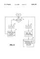
- FIG. 6is a software flowchart depicting the operation of the functional operation of the analog front end element, illustrated in FIG. 5;
- FIG. 7is a software flowchart illustrating the top-level operation of a system constructed in accordance with the present invention.
- FIG. 1is a diagram illustrating frequency band communications, as is known in the prior art.
- the term frequency band communicationsis used to indicate communication of information within a certain defined, frequency band.
- POTSplain old telephone system
- a second transmission frequency band 14is defined at a higher frequency level than the POTS frequency band 12, and is used in the transmission of digital subscriber line (DSL) communications.
- a guard dead band 16is typically provided to separate the two transmission frequency bands 12 and 14.
- the DSL transmission frequency band 14is more broadly denominated as "xDSL", wherein the "x" generically denominates any of a number of transmission techniques within the DSL family.
- xDSL transmission frequency bands 14may encompass a bandwidth of greater than I MHz.
- xDSL signalsare not compatible with attached POTS type equipment, such as telephones, PSTN modems, facsimile machines, etc.
- the present inventionprovides an upper transmission band having an upper frequency boundary that is much lower than the 1 MHz frequency boundary often encountered in xDSL transmissions.
- the upper frequency boundary of the present inventionis defined in a range that is readily supported by, or compatible with, transmission systems (and attached POTS-type equipment) presently in place between a customer premises and a central office, without the need for extraneous devices such as POTS filters and POTS splitters.
- FIG. 2is a top level diagram illustrating the principal hardware components of a system utilizing the present invention.
- a modem 20is provided for achieving efficient data communications between a customer premises 22 and a central office 24 across a local loop 26, by dynamically allocating a transmission frequency bandwidth and/or power for transmitting data.
- a modem 20is provided for achieving efficient data communications between a customer premises 22 and a central office 24 across a local loop 26, by dynamically allocating a transmission frequency bandwidth and/or power for transmitting data.
- the present inventiondynamically allocates a data transmission frequency band and/or power spectral density (PSD) in response to POTS communications across the same line. More particularly, the present invention may utilize the frequency band otherwise allocated for POTS/voice transmission, at times when there is no present demand for transmitting voice information. When, however, there is a demand for voice transmissions, then the present invention reallocates the transmission frequency band and PSD for the data communications so that there is no overlap or interference with the POTS transmission frequency band 12, and so that there is not significant interference to POTS-type attached equipment.
- PSDpower spectral density
- the customer premises 22may be a single-family household having a single phone line 26 for communicating between the customer premises 22 and a central office 24.
- multiple connectionsbranch off of the local loop 26 and are terminated at phone jacks (such as RJ-11) located in various rooms of the household.
- phone jackssuch as RJ-11
- a personal computermay be disposed in communication with the local loop 26 by way of a modem 20.
- FIG. 2also illustrates a variety of services that may be connected at the central office 24 to the mode 40, constructed in accordance with the present invention. These services may include a high speed ISP service 44, a high speed LAN access service 46, etc. Again, since the provision and operation of such services are generally understood and are further not necessary in order to describe the operation of the present invention, they will not be described herein.
- FIG. 3Aillustrates the data transmission frequency band 50 in a full-band transmission frequency state
- FIG. 3Billustrates a data transmission frequency band 52 in a band-limited (POTS compatible) transmission frequency state.
- the full-band transmission frequency band 50extends from approximately 0 Hz (DC) to approximately 100 KHz.
- the data transmission frequency band 52extends from approximately 20 KHz to approximately 100 KHz.
- a modem 20 constructed in accordance with the inventionsenses the need to dynamically allocate or deallocate a portion of the transmission frequency band in order to accommodate voice communications within the 0 to 4 KHz POTS frequency band 12.
- the present inventionmay sense this demand for voice transmissions (or band-limiting condition) by sensing an OFF-HOOK condition of a telephone 30, 32, (see FIG. 2) connected to the local loop 26.
- this band-limiting conditionmay be detected by an impedance change on the local loop 26.
- the systemmay also be configured to detect voice conversation. Upon voice detection, the system may increase transmit power as it shifts into the band-limited transmission state, to increase data rate dynamically, so long as the voice band SNR is about 30 to 40 dB. When silence is once again detected (for a predetermined amount of time), the system will again reduce the transmit power for good idle channel perception.
- the data transmission frequency band of the present inventionis much less than that. This permits relatively high-speed data communication without the addition of expensive equipment, such as POTS splitters and POTS filters. Importantly, this addresses a market need from consumers that do not wish to incur, or cannot afford, the additional expenses normally incurred with purchasing an xDSL communication service.
- An important aspect of the present inventionis its ability to sense when voice-band communications are not occurring, or otherwise when a band-limiting condition is not present, and expand the transmission frequency band into the frequency band otherwise reserved for POTS transmissions, and/or increase transmit power to increase the data rate. As can be seen from the illustrations in FIGS.
- FIGS. 3C and 3Dillustrate alternative embodiments of the present invention.
- FIGS. 3C and 3Dillustrate a spectrally-shaped transmission curve and an adaptive power transmission curve, respectively.
- the power density of the xDSL transmission bandis greater than that of the POTS transmission band.
- the guard band 16is not large enough to sufficiently separate the xDSL transmission band 52 from the POTS frequency band 12.
- xDSL transmissionsmay be evident in the POTS frequency band 12 as noise (audible static). The reasons this may occur are varied, and include factors such as telephone set sensitivity and non-linearities. Intermodulation products may also be manifest within the POTS transmission band 12 as noise.
- FIG. 3CYet another solution is to more particularly define the spectral shape of the transmission band.
- This solutionis illustrated in FIG. 3C.
- the power spectrum of the xDSL transmission band 54may be asymmetrically shaped to provide a greater taper on the lower frequency end of the curve. This taper, ensures sufficient attenuation of the xDSL transmission signal above the POTS frequency band 12, and therefore minimizes intermodulation products and noise (resulting from the xDSL transmission) within the POTS band 12.
- FIG. 3Donly one such shaped signal band 56 is illustrated in FIG. 3D, it will be appreciated that this aspect of the invention is not so limited. Instead, other shapes may be deemed desirable, depending upon the specific environment and line conditions.
- FIG. 4shows a block diagram of a modem 20 constructed in accordance with the present invention.
- the modem 20is in communication with both a local loop 26 and computing equipment 25, such as a personal computer. More specifically, the modem 20 communicates with the computing equipment 25 across line 60.
- the telephone line 26is typically comprised of a two wire service, which wires are often denoted as TIP 62 and RING 64.
- the TIP 62 and RING 64 linesare input to an analog front-end circuit 66 (see FIG. 5) as well as a monitor circuit 68, which is configured to detect an OFF-HOOK condition of the local loop 26.
- Analog-to-digital and digital-to-analog converter (ADC and DAC, respectively) circuitry 70is in communication with the analog front end circuitry 66, and is in further communication with digital signal processor 72.
- Data received from the local loop 26passes through the analog front-end 66 and is converted from analog-to-digital form by the analog to digital converter of block 70, before being passed to the digital signal processor 72.
- outgoing data output from the digital signal processor 72is converted by the digital to analog converter of block 70, before being communicated to the local loop 26, by way of the analog front-end 66.
- Data Terminal Equipment (DTE) interface 74is in communication with the digital signal processor 72 and in further communication across line 60, with the data terminal equipment, such as a computer 25.
- DTEData Terminal Equipment
- a significant component of the modem 20, constructed in accordance with the present inventionis a controller 80 that is in communication with the various other components of the modem 20. While there are various ways to implement the controller 80, one way, as illustrated, is to further partition the controller 80 into functional units denoted as a processing unit 82, a memory 84 (which may further include an executable code segment 86), and a controller 88.
- the controller 80receives a signal from the monitor circuit 68 on line 90, which signal indicates whether the invention should transmit data in a band-limited transmission state or a full-band transmission state.
- the monitor circuitry 68may be configured to detect an OFF-HOOK condition, or alternatively, a RING condition on local loop 26.
- the OFF-HOOK conditionmay be detected by a drop in voltage across the local loop 26, or alternatively, a sudden chance in impedance on the local loop 26.
- a RING detect conditionis identified by a low frequency oscillatory voltage on local loop 26. For example, the voltage drops from about 48 volts (on hook) to approximately 10 volts or less (off hook), at the customer premises end of the local loop.
- the controller 80evaluates the signal received on line 90 to determine whether data should be transmitted in the full-band transmission state or the band-limited transmission state. Appropriate signals may, accordingly, be transmitted to the digital signal processor 72 for formulating data transmissions (or interpreting received data transmissions).
- the monitor circuitry 68may be incorporated within the controller 80, whereby certain signal conditions may be evaluated to detect the band-limiting condition.
- an analog-to-digital converterwould also be implemented as part of the controller 80, to generate a signal in digital format which may be more readily evaluated and processed by the processing unit 82.
- the processing unit 82may be a microprocessor, a microcontroller, an application specific integrated circuit (ASIC), or other digital circuitry configured to specifically process information.
- the controller 80includes fundamental components (processor unit, controller, memory) that together operate to perform distinct computing operations. Such operations may be controlled, for example, by executable code 86 contained within the memory 84.
- FIG. 5shows a more detailed diagram of the circuitry comprising the analog front end element 66.
- the preferred embodimentincludes blocking capacitors 102 and 104, which are series connected with the TIP 62 and RING 64 signal lines, and serve to block any DC voltage otherwise carried on the TIP 62 and RING 64 lines.
- a transformer 106couples alternating current to the remainder of the circuitry, as well as provides safety and signal isolation for the remaining circuitry in the modem.
- a termination resistor 108 and switch 110are disposed for series connection with each other (depending upon whether the switch 110 is opened or closed), and together are connected in parallel across the secondary winding of the transformer 106.
- the switch 110is controlled by controller 80 (FIG.
- the switch 110may be open to switch out the terminating resistor 108, upon detection of an incoming RING signal or OFF-HOOK on the local loop 26.
- Capacitors 102 and 104are chosen to pass data, block DC, and yield acceptable Ringer Equivalence Number per FCC part 68.
- the switch 110is generally opened to switch out the terminating resistor when the monitor circuit 68 determines that the local loop 26 is in the OFF-HOOK state.
- the switch 110can be closed in the Off-HOOK state to improve line termination provided by the OFF-HOOK telephone.
- the item represented by reference numeral 112denotes circuitry that is configured in a form of a dependent current source.
- the current sourceis prompted by the transmit signal Tx to create an outgoing transmission signal.
- the item 112has a very high impedance (as seen across the secondary winding of transformer 106), and therefore, only the termination resistor 108 operates to terminate the line (when switched in).
- amplifier 114is the receive amplifier that generates the Rx signal, as is known in the art. Like the current source 112, the amplifier 114 has an extremely high input impedance and thus does not effect line termination.
- FIG. 6shows a software flow-chart illustrating the operation of the analog front-end element 66 of FIG. 5.
- the element 66determines whether the local loop 26 is ON-HOOK or OFF-HOOK. As will be appreciated from the foregoing discussion, this decision is made by the controller 80, which outputs a signal 122 (see FIG. 4) to the analog front-end 66 indicative of the ON-HOOK/OFF-HOOK status. If the resolution of step 120 is NO, the analog front-end element 66 opens switch 112 (step 122) to remove the termination resistor 108 from the circuit.
- step 122data is transmitted in accordance with the band-limited transmission frequency band (e.g., 20 kHz-100 kHz).
- the systemmay emit periodic tones within the audible frequency range to alert a user talking on an attached telephone that the local loop 26 is also being used for data transmissions.
- a personfor example, speaking in another part of the house over a telephone hearing periodic beeps would know that someone else in the household is using a computer to communicate data, and therefore, may wish to keep his or her conversation to a minimum, in order to free up the local loop 26, so that the present invention may obtain a full utilization of the full-banded transmission frequency band, for maximum data throughput.
- step 120If the resolution of step 120 is YES, indicating that all telephones attached to the local loop 26 are ON-HOOK, then the system ensures that switch 110 is closed thereby placing termination resistor 108 in the circuit, so as to achieve proper line termination (step 130). Thereafter, the system may transmit data across the local loop utilizing the entire, full-band transmission frequency (i.e., DC to approximately 100 KHz).
- the entire, full-band transmission frequencyi.e., DC to approximately 100 KHz.
- FIG. 7is a software flow-chart illustrating the top-level operation of a system communicating in accordance with the present invention.
- the systemawaits the initiation of data transmission. This initiation may occur either upon the instruction of a user at the computer 25 (see FIG. 2), or alternatively, from a remote user that is dialing the phone number of computer 25 to connect up to that computer (this assumes that that computer 25 is in auto answer mode).
- the systemfirst makes a check (at step 144) to determine whether the loop is in the OFF-HOOK state. If so, it begins the data communications in the band-limited frequency transition state (step 146) (e.g., 20 kHz-100 kHz).
- the systemwill make continuous checks to determine whether the data transmission has ended (step 148, or whether the band-limiting condition has subsided (step 150).
- the band-limiting conditionis generally identified by the OFF-HOOK detection circuitry. If the end data communications check, at step 148, resolves to YES, then the system returns to step 140. If not, the system proceeds to step 150 where it checks for the cessation of the band-limiting condition. If this step resolves to YES, then the system continues the data transmission in the full-band transmission frequency bandwidth (step 154).
- step 154transmits data in accordance with the full-band data transmission state (i.e., utilizing the full 0 to 100 KHz transmission frequency bandwidth).
- the systemperiodically checks to see if the data communications has terminated (step 156), or whether the occurrence of a band-limiting condition has occurred (step 158). This latter condition occurs, for example, when a person lifts a handset of an attached telephone. If this occurs, the system proceeds to step 146 and continues the data transmissions in accordance with the band-limited transmission frequency band (20 kHz-100 kHz).
- the invention described hereincould provide a low-cost solution to Internet access for the mass consumer market. In this regard, it could fill the gap between low-cost 33.6 kbps modems and high speed xDSL modems, which require the addition of relatively expensive equipment (such as POTS splitters and POTS filters) at the customer premise, and is labor intensive.
- the present inventionas described above, generally achieves transmission rates in the range of 64 kbps to 640 kbps.
- the inventionutilizes the low frequency portion of the telephone subscriber loop spectrum (roughly DC to approximately 100 KHz) to transport user data.
- the modulationcould be CAP (carrierless amplitude-phase), QAM (quadrature amplitude modulation), DMT (dual multi-tone), spread spectrum, etc, as the invention is not limited to any particular form.
- Utilization of the lower frequency portion of the telephone subscriber loophas the advantage of the lowest possible signal attenuation (usually the number one signal impairment in data communications) and low cross-talk. Other advantages are reduced transmission line concerns like reflections due to stubs.
- the inventionrequires a simple bridge (electrical parallel) connection to the subscriber loop or premise wiring. Therefore, one unit would connect (in bridge fashion) at the central office, and one companion unit connect at the customer premises.
Landscapes
- Engineering & Computer Science (AREA)
- Signal Processing (AREA)
- Computer Networks & Wireless Communication (AREA)
- Quality & Reliability (AREA)
- Telephonic Communication Services (AREA)
Abstract
Description
Claims (54)
Priority Applications (8)
| Application Number | Priority Date | Filing Date | Title |
|---|---|---|---|
| US08/962,796US6061392A (en) | 1996-12-17 | 1997-11-03 | Apparatus and method for communicating voice and data between a customer premises and a central office |
| CA002272576ACA2272576A1 (en) | 1996-12-17 | 1997-12-04 | Apparatus and method for communicating voice and data between a customer premises and a central office |
| PCT/US1997/022632WO1998027665A1 (en) | 1996-12-17 | 1997-12-04 | Apparatus and method for communicating voice and data between a customer premises and a central office |
| JP52780298AJP2001526849A (en) | 1996-12-17 | 1997-12-04 | Apparatus and method for transmitting voice and data between subscriber premises and central office |
| US09/374,774US6546090B1 (en) | 1996-12-17 | 1999-08-16 | Apparatus and method for communicating voice and data between a customer premises and a central office |
| US10/811,531US7130338B2 (en) | 1996-12-17 | 2004-03-29 | Apparatus and method for communicating voice and data between a customer premises and a central office |
| US10/926,827US20050074057A1 (en) | 1997-11-03 | 2004-08-26 | System and method for modulation on demand in a computing device |
| US11/589,375US7352803B2 (en) | 1996-12-17 | 2006-10-30 | Apparatus and method for communicating voice and data between a customer premises and a central office |
Applications Claiming Priority (2)
| Application Number | Priority Date | Filing Date | Title |
|---|---|---|---|
| US3366096P | 1996-12-17 | 1996-12-17 | |
| US08/962,796US6061392A (en) | 1996-12-17 | 1997-11-03 | Apparatus and method for communicating voice and data between a customer premises and a central office |
Related Child Applications (2)
| Application Number | Title | Priority Date | Filing Date |
|---|---|---|---|
| US21373298AContinuation-In-Part | 1997-11-03 | 1998-12-16 | |
| US09/374,774DivisionUS6546090B1 (en) | 1996-12-17 | 1999-08-16 | Apparatus and method for communicating voice and data between a customer premises and a central office |
Publications (1)
| Publication Number | Publication Date |
|---|---|
| US6061392Atrue US6061392A (en) | 2000-05-09 |
Family
ID=26709972
Family Applications (2)
| Application Number | Title | Priority Date | Filing Date |
|---|---|---|---|
| US08/962,796Expired - LifetimeUS6061392A (en) | 1996-12-17 | 1997-11-03 | Apparatus and method for communicating voice and data between a customer premises and a central office |
| US09/374,774Expired - LifetimeUS6546090B1 (en) | 1996-12-17 | 1999-08-16 | Apparatus and method for communicating voice and data between a customer premises and a central office |
Family Applications After (1)
| Application Number | Title | Priority Date | Filing Date |
|---|---|---|---|
| US09/374,774Expired - LifetimeUS6546090B1 (en) | 1996-12-17 | 1999-08-16 | Apparatus and method for communicating voice and data between a customer premises and a central office |
Country Status (1)
| Country | Link |
|---|---|
| US (2) | US6061392A (en) |
Cited By (90)
| Publication number | Priority date | Publication date | Assignee | Title |
|---|---|---|---|---|
| WO2000073741A1 (en) | 1999-05-27 | 2000-12-07 | Qwest Communications International Inc. | Method and system for providing telephony services via dsl |
| US6192109B1 (en)* | 1997-12-24 | 2001-02-20 | Globespan, Inc. | Apparatus and method for improved DSL communication |
| US6266395B1 (en)* | 1999-08-31 | 2001-07-24 | Nortel Networks Limited | Single-ended subscriber loop qualification for xDSL service |
| US6269154B1 (en)* | 1998-02-04 | 2001-07-31 | Texas Instruments Incorporated | Splitterless modem with integrated off-hook detector |
| WO2001059946A1 (en)* | 2000-02-10 | 2001-08-16 | Telogy Networks, Inc. | A generalized precoder for the upstream voiceband modem channel |
| US6301337B1 (en)* | 1997-09-18 | 2001-10-09 | Globespan, Inc. | Combined handset and POTS filter |
| US6304593B1 (en)* | 1997-10-06 | 2001-10-16 | California Institute Of Technology | Adaptive modulation scheme with simultaneous voice and data transmission |
| US6324268B1 (en)* | 1999-03-01 | 2001-11-27 | Ericsson Inc. | Splitter-less digital subscriber loop modems with improved throughput and voice and data separation |
| US6324212B1 (en)* | 1999-02-12 | 2001-11-27 | Siemens Information And Communication Networks, Inc. | Apparatus using low spectrum selectively for providing both ADSL and POTS service |
| WO2001091440A1 (en)* | 2000-05-22 | 2001-11-29 | Infineon Technologies Ag | INTEGRATED TELEPHONE SET WITH AN xDSL-MODEM |
| WO2001043415A3 (en)* | 1999-12-09 | 2002-02-14 | 3Com Corp | Method for reducing noise from an asymmetric digital subscriber line modem |
| US6363079B1 (en)* | 1997-12-31 | 2002-03-26 | At&T Corp. | Multifunction interface facility connecting wideband multiple access subscriber loops with various networks |
| US6373860B1 (en)* | 1998-07-29 | 2002-04-16 | Centillium Communications, Inc. | Dynamically-assigned voice and data channels in a digital-subscriber line (DSL) |
| US20020048275A1 (en)* | 1997-12-16 | 2002-04-25 | Antonio Atwater | Method and apparatus for receiving full-motion digital video multi-casts, interactive data and interactive voice via a DSL circuit |
| US20020064267A1 (en)* | 2000-03-31 | 2002-05-30 | Robert Martin | Telecommunications portal capable of interpreting messages from an external device |
| US20020093985A1 (en)* | 1998-09-02 | 2002-07-18 | Prasad Nimmagadda | Method and system for selection of mode of operation of a service in light of use of another service in an ADSL system |
| US6442248B1 (en)* | 2000-01-12 | 2002-08-27 | Multi-Tech Systems, Inc. | System for providing analog and digital telephone functions using a single telephone line |
| US6466588B1 (en)* | 1997-09-18 | 2002-10-15 | Globespanvirata, Inc. | Apparatus for facilitating combined POTS and xDSL services at a customer premises |
| US20030007621A1 (en)* | 1999-03-06 | 2003-01-09 | Graves Richard C. | Systems and processes for call and call feature administration on a telecommunications network |
| US6510133B1 (en)* | 1997-05-30 | 2003-01-21 | Matsushita Electric Industrial Co., Ltd. | Multi-carrier transmission method and data transmitter |
| US20030016794A1 (en)* | 1998-05-14 | 2003-01-23 | John D.W. Brothers | Communication of information via two wire lines |
| US20030016731A1 (en)* | 2000-03-15 | 2003-01-23 | Mitsuru Uesugi | Transmitter, receiver, and method of data transmission |
| US6522730B1 (en)* | 1999-01-15 | 2003-02-18 | Texas Instruments Incorporated | DSL communication system with improved bandwidth |
| US6522731B2 (en)* | 1998-04-24 | 2003-02-18 | Mitsubishi Denki Kabushiki Kaisha | Data communication apparatus |
| US20030041237A1 (en)* | 2001-08-22 | 2003-02-27 | Adtran, Inc. | Mechanism for automatically configuring integrated access device for use in voice over digital subscriber line circuit |
| US20030043785A1 (en)* | 2001-08-23 | 2003-03-06 | Ming-Kang Liu | Configurable digital subscriber loop access and end-to-end data and analog voice connection system |
| US6535589B1 (en)* | 1999-09-13 | 2003-03-18 | Paradyne Corporation | Method and apparatus for reducing transmission errors in digital subscriber line (DSL) communication systems |
| US20030059011A1 (en)* | 2001-09-27 | 2003-03-27 | Alcatel | Modem and method |
| US6546090B1 (en)* | 1996-12-17 | 2003-04-08 | Paradyne Corporation | Apparatus and method for communicating voice and data between a customer premises and a central office |
| US6563864B1 (en)* | 1998-02-04 | 2003-05-13 | Texas Instruments Incorporated | Residential power cutback for splitterless DSL operation |
| US20030112763A1 (en)* | 2001-12-17 | 2003-06-19 | Gin Liu | Communications channel performance determination for high-speed access |
| US6584122B1 (en)* | 1998-12-18 | 2003-06-24 | Integral Access, Inc. | Method and system for providing voice and data service |
| US6647024B1 (en)* | 1999-05-07 | 2003-11-11 | Lucent Technologies Inc. | System and method for an all digital communication system with a life line |
| US20030210779A1 (en)* | 2002-05-08 | 2003-11-13 | Paradyne Corporation | Automatic rapid switching between DSL service and POTS over loaded loops |
| US6650697B1 (en)* | 1998-09-18 | 2003-11-18 | Nortel Networks Limited | Wireline communication system and method of frequency allocation therein |
| US20040008761A1 (en)* | 2002-07-12 | 2004-01-15 | Kelliher Timothy L. | Faster modem method and apparatus |
| US6704324B1 (en)* | 1998-03-25 | 2004-03-09 | Paradyne Corporation | Apparatus and method for transmission of voice band signals over a DSL line |
| US20040081298A1 (en)* | 2002-10-29 | 2004-04-29 | Strauss Steven E. | Dynamic frequency passband switching in home phone-line networks |
| US20040085987A1 (en)* | 1997-10-10 | 2004-05-06 | Aware, Inc. | Splitterless multicarrier modem |
| US20040146072A1 (en)* | 2001-09-13 | 2004-07-29 | Pedestal Networks Incorporated | System for enhancing data transfer |
| US20040146068A1 (en)* | 1999-10-22 | 2004-07-29 | Naom Chaplik | Method and system for combining symmetric DSL signals and voice signals |
| US20040153544A1 (en)* | 2003-01-30 | 2004-08-05 | Kelliher Timothy L. | Universal broadband server system and method |
| US20040201933A1 (en)* | 2003-04-09 | 2004-10-14 | Blanc James Joseph | Method and apparatus for aggregating power from multiple sources |
| US20040233979A1 (en)* | 2003-05-20 | 2004-11-25 | Surf Communication | Long range broadband modem |
| US6829251B2 (en) | 2001-12-10 | 2004-12-07 | Globespanvirata, Inc | System and method for increasing data capacity in communication systems |
| US6839343B2 (en) | 2003-01-30 | 2005-01-04 | Pedestal Networks, Inc. | Physical layer router system and method |
| US6845157B1 (en) | 2000-02-14 | 2005-01-18 | Paradyne Corporation | Linear polarity guard and method for DSL-ready pots devices |
| US20050078690A1 (en)* | 2003-10-14 | 2005-04-14 | Delangis Eric M. | Residential communications gateway (RCG) for broadband communications over a plurality of standard POTS lines, with dynamic allocation of said bandwidth, that requires no additional equipment or modifications to the associated class 5 offices or the PSTN at large |
| US20050147158A1 (en)* | 1999-05-17 | 2005-07-07 | Paradyne Corporation | Method and apparatus for automatic selection and operation of a subscriber line spectrum class technology |
| US6925157B1 (en)* | 1999-01-18 | 2005-08-02 | Siemens Aktiengesellschaft | Method for operating devices for transmitting high-bit-rate data on an extension line and arrangement having such devices for data transmission |
| US6970924B1 (en) | 1999-02-23 | 2005-11-29 | Visual Networks, Inc. | Methods and apparatus for monitoring end-user experience in a distributed network |
| US20060159116A1 (en)* | 1997-12-31 | 2006-07-20 | Irwin Gerszberg | Facility management platform for a hybrid coaxial/twisted pair local loop network service architecture |
| US7142590B2 (en) | 2001-10-11 | 2006-11-28 | Utstarcom Inc. | Method and system for oversubscribing a DSL modem |
| US7142591B2 (en) | 2001-10-11 | 2006-11-28 | Utstarcom, Inc. | Method and system for oversubscribing a pool of modems |
| US7173944B1 (en)* | 1997-12-02 | 2007-02-06 | Conexant Systems, Inc. | Modulation switching for DSL signal transmission |
| US7227933B1 (en) | 2000-01-12 | 2007-06-05 | Multi-Tech Systems, Inc. | System and method for remote management of a DSL device |
| US20070127454A1 (en)* | 2001-04-24 | 2007-06-07 | General Bandwidth Inc. | System and Method for Providing Lifeline Telecommunication Service |
| US7274688B2 (en) | 2000-04-18 | 2007-09-25 | Serconet Ltd. | Telephone communication system over a single telephone line |
| US7317793B2 (en) | 2003-01-30 | 2008-01-08 | Serconet Ltd | Method and system for providing DC power on local telephone lines |
| US20080019432A1 (en)* | 1996-12-17 | 2008-01-24 | Paradyne Corporation | Apparatus and method for communicating voice and data between a customer premises and a central office |
| US7436842B2 (en) | 2001-10-11 | 2008-10-14 | Serconet Ltd. | Outlet with analog signal adapter, a method for use thereof and a network using said outlet |
| US7483524B2 (en) | 1999-07-20 | 2009-01-27 | Serconet, Ltd | Network for telephony and data communication |
| US7522714B2 (en) | 2000-03-20 | 2009-04-21 | Serconet Ltd. | Telephone outlet for implementing a local area network over telephone lines and a local area network using such outlets |
| US7542554B2 (en) | 2001-07-05 | 2009-06-02 | Serconet, Ltd | Telephone outlet with packet telephony adapter, and a network using same |
| US7587001B2 (en) | 2006-01-11 | 2009-09-08 | Serconet Ltd. | Apparatus and method for frequency shifting of a wireless signal and systems using frequency shifting |
| US7633966B2 (en) | 2000-04-19 | 2009-12-15 | Mosaid Technologies Incorporated | Network combining wired and non-wired segments |
| US7686653B2 (en) | 2003-09-07 | 2010-03-30 | Mosaid Technologies Incorporated | Modular outlet |
| US7737841B2 (en) | 2006-07-14 | 2010-06-15 | Remotemdx | Alarm and alarm management system for remote tracking devices |
| US20100183055A1 (en)* | 1997-12-05 | 2010-07-22 | Bremer Gordon F | System and Method of Communication Via Embedded Modulation |
| US7804412B2 (en) | 2005-08-10 | 2010-09-28 | Securealert, Inc. | Remote tracking and communication device |
| US7873058B2 (en) | 2004-11-08 | 2011-01-18 | Mosaid Technologies Incorporated | Outlet with analog signal adapter, a method for use thereof and a network using said outlet |
| US7936262B2 (en) | 2006-07-14 | 2011-05-03 | Securealert, Inc. | Remote tracking system with a dedicated monitoring center |
| US20110220289A1 (en)* | 2008-12-02 | 2011-09-15 | Kabushiki Kaisha Kobe Seiko Sho (Kobe Steel, Ltd.) | Member for plasma treatment apparatus and production method thereof |
| US8175649B2 (en) | 2008-06-20 | 2012-05-08 | Corning Mobileaccess Ltd | Method and system for real time control of an active antenna over a distributed antenna system |
| US8232876B2 (en) | 2008-03-07 | 2012-07-31 | Securealert, Inc. | System and method for monitoring individuals using a beacon and intelligent remote tracking device |
| US8238328B2 (en) | 2003-03-13 | 2012-08-07 | Mosaid Technologies Incorporated | Telephone system having multiple distinct sources and accessories therefor |
| US8270430B2 (en) | 1998-07-28 | 2012-09-18 | Mosaid Technologies Incorporated | Local area network of serial intelligent cells |
| US8325759B2 (en) | 2004-05-06 | 2012-12-04 | Corning Mobileaccess Ltd | System and method for carrying a wireless based signal over wiring |
| US8514070B2 (en) | 2010-04-07 | 2013-08-20 | Securealert, Inc. | Tracking device incorporating enhanced security mounting strap |
| US8594133B2 (en) | 2007-10-22 | 2013-11-26 | Corning Mobileaccess Ltd. | Communication system using low bandwidth wires |
| US20140050228A1 (en)* | 1999-07-07 | 2014-02-20 | Mosaid Technologies Incorporated | Local area network for distributing data communication, sensing and control signals |
| US8797210B2 (en) | 2006-07-14 | 2014-08-05 | Securealert, Inc. | Remote tracking device and a system and method for two-way voice communication between the device and a monitoring center |
| US8897215B2 (en) | 2009-02-08 | 2014-11-25 | Corning Optical Communications Wireless Ltd | Communication system using cables carrying ethernet signals |
| US20150085907A1 (en)* | 2012-03-30 | 2015-03-26 | British Telecommunications Public Limited Company | Method and apparatus for providing data and telephony services |
| US9184960B1 (en) | 2014-09-25 | 2015-11-10 | Corning Optical Communications Wireless Ltd | Frequency shifting a communications signal(s) in a multi-frequency distributed antenna system (DAS) to avoid or reduce frequency interference |
| US9338823B2 (en) | 2012-03-23 | 2016-05-10 | Corning Optical Communications Wireless Ltd | Radio-frequency integrated circuit (RFIC) chip(s) for providing distributed antenna system functionalities, and related components, systems, and methods |
| US9432172B2 (en) | 1997-12-05 | 2016-08-30 | Rembrandt Wireless Technologies, Lp | System and method of communication using at least two modulation methods |
| US10771110B2 (en) | 2016-11-08 | 2020-09-08 | British Telecommunications Public Limited Company | Method and apparatus for operating a digital subscriber line arrangement |
| US10986164B2 (en) | 2004-01-13 | 2021-04-20 | May Patents Ltd. | Information device |
| US11201969B2 (en) | 2016-11-08 | 2021-12-14 | British Telecommunications Public Limited Company | Method and apparatus for operating a digital subscriber line arrangement |
Families Citing this family (15)
| Publication number | Priority date | Publication date | Assignee | Title |
|---|---|---|---|---|
| US6580785B2 (en)* | 1997-02-28 | 2003-06-17 | Paradyne Corporation | Apparatus and method for simultaneous multiple telephone type services on a single telephone line |
| US7035380B1 (en)* | 2000-02-16 | 2006-04-25 | Paradyne Corporation | Line sharing multipoint POTS splitter with intelligent termination |
| US6418160B1 (en)* | 2000-03-29 | 2002-07-09 | Sbc Technology Resources, Inc. | Method for testing a communication channel |
| CA2303631A1 (en)* | 2000-03-31 | 2001-09-30 | Catena Networks Canada Inc. | A system and method for programmable spectrum management |
| US6738418B1 (en)* | 2000-04-03 | 2004-05-18 | Virata Corporation | Method and apparatus for adaptive data allocation in a multi-carrier communication system |
| US6895041B1 (en)* | 2000-06-23 | 2005-05-17 | Cisco Technology, Inc. | Digital subscriber line power reduction |
| SE0004036D0 (en)* | 2000-11-03 | 2000-11-03 | Ericsson Telefon Ab L M | Apparatus and method for provision of a back-up connection in a telecommunication system |
| US6963641B1 (en) | 2000-12-19 | 2005-11-08 | Cisco Technology, Inc. | Method and apparatus for providing variable attenuation to data signals in an XDSL frequency range |
| US20020172274A1 (en)* | 2001-05-18 | 2002-11-21 | Carlson Arthur J. | Method of intelligently restricting symbol size in ADSL modems |
| JP3627680B2 (en) | 2001-06-20 | 2005-03-09 | 日本電気株式会社 | Bandwidth control system and control method in digital subscriber line network |
| US7406117B2 (en)* | 2002-03-21 | 2008-07-29 | Westell Technologies, Inc. | XDSL multi-hybrid modem with power spectral density shaping |
| US7620154B2 (en)* | 2002-12-23 | 2009-11-17 | Cambron G Keith | Equivalent working length determinative system for digital subscriber line circuits |
| US7386319B2 (en)* | 2003-01-08 | 2008-06-10 | Vtech Telecommunications Limited | System and method for two-way messaging between a personal computer and a cordless device including stereo |
| DE10352056B4 (en)* | 2003-11-07 | 2006-04-20 | Infineon Technologies Ag | Hybrid DSL system for transmitting hybrid DSL data over a subscriber line to increase overall data transmission rate and optimize transmission ranges of both transceivers |
| US20060149845A1 (en)* | 2004-12-30 | 2006-07-06 | Xinnia Technology, Llc | Managed quality of service for users and applications over shared networks |
Citations (6)
| Publication number | Priority date | Publication date | Assignee | Title |
|---|---|---|---|---|
| US3875339A (en)* | 1972-09-05 | 1975-04-01 | I I Communications Inc | Variable bandwidth voice and data telephone communication system |
| US4442540A (en)* | 1981-06-04 | 1984-04-10 | Bell Telephone Laboratories, Incorporated | Data over voice transmission arrangement |
| US4757495A (en)* | 1986-03-05 | 1988-07-12 | Telebit Corporation | Speech and data multiplexor optimized for use over impaired and bandwidth restricted analog channels |
| US5410343A (en)* | 1991-09-27 | 1995-04-25 | Bell Atlantic Network Services, Inc. | Video-on-demand services using public switched telephone network |
| US5463616A (en)* | 1993-01-07 | 1995-10-31 | Advanced Protocol Systems, Inc. | Method and apparatus for establishing a full-duplex, concurrent, voice/non-voice connection between two sites |
| US5553063A (en)* | 1994-09-12 | 1996-09-03 | Dickson; William D. | Voice over data communication system |
Family Cites Families (6)
| Publication number | Priority date | Publication date | Assignee | Title |
|---|---|---|---|---|
| JP2649795B2 (en)* | 1986-02-26 | 1997-09-03 | キヤノン株式会社 | Communication device |
| US5003579A (en)* | 1986-08-22 | 1991-03-26 | Farallon Computing, Incorporated | System for connecting computers via telephone lines |
| US4821312B1 (en)* | 1987-10-14 | 1991-06-25 | Voice/data switch | |
| US4953160A (en)* | 1988-02-24 | 1990-08-28 | Integrated Network Corporation | Digital data over voice communication |
| US5475691A (en)* | 1993-11-15 | 1995-12-12 | At&T Corp. | Voice activated date rate change in simultaneous voice and data transmission |
| US6061392A (en)* | 1996-12-17 | 2000-05-09 | Paradyne Corporation | Apparatus and method for communicating voice and data between a customer premises and a central office |
- 1997
- 1997-11-03USUS08/962,796patent/US6061392A/ennot_activeExpired - Lifetime
- 1999
- 1999-08-16USUS09/374,774patent/US6546090B1/ennot_activeExpired - Lifetime
Patent Citations (6)
| Publication number | Priority date | Publication date | Assignee | Title |
|---|---|---|---|---|
| US3875339A (en)* | 1972-09-05 | 1975-04-01 | I I Communications Inc | Variable bandwidth voice and data telephone communication system |
| US4442540A (en)* | 1981-06-04 | 1984-04-10 | Bell Telephone Laboratories, Incorporated | Data over voice transmission arrangement |
| US4757495A (en)* | 1986-03-05 | 1988-07-12 | Telebit Corporation | Speech and data multiplexor optimized for use over impaired and bandwidth restricted analog channels |
| US5410343A (en)* | 1991-09-27 | 1995-04-25 | Bell Atlantic Network Services, Inc. | Video-on-demand services using public switched telephone network |
| US5463616A (en)* | 1993-01-07 | 1995-10-31 | Advanced Protocol Systems, Inc. | Method and apparatus for establishing a full-duplex, concurrent, voice/non-voice connection between two sites |
| US5553063A (en)* | 1994-09-12 | 1996-09-03 | Dickson; William D. | Voice over data communication system |
Cited By (197)
| Publication number | Priority date | Publication date | Assignee | Title |
|---|---|---|---|---|
| US7352803B2 (en) | 1996-12-17 | 2008-04-01 | Paradyne Corporation | Apparatus and method for communicating voice and data between a customer premises and a central office |
| US6546090B1 (en)* | 1996-12-17 | 2003-04-08 | Paradyne Corporation | Apparatus and method for communicating voice and data between a customer premises and a central office |
| US20080019432A1 (en)* | 1996-12-17 | 2008-01-24 | Paradyne Corporation | Apparatus and method for communicating voice and data between a customer premises and a central office |
| US6510133B1 (en)* | 1997-05-30 | 2003-01-21 | Matsushita Electric Industrial Co., Ltd. | Multi-carrier transmission method and data transmitter |
| US6608842B2 (en) | 1997-09-18 | 2003-08-19 | Globespanvirata, Inc. | Apparatus for facilitating combined POTS and xDSL services at a customer premises |
| US6466588B1 (en)* | 1997-09-18 | 2002-10-15 | Globespanvirata, Inc. | Apparatus for facilitating combined POTS and xDSL services at a customer premises |
| US6301337B1 (en)* | 1997-09-18 | 2001-10-09 | Globespan, Inc. | Combined handset and POTS filter |
| US6304593B1 (en)* | 1997-10-06 | 2001-10-16 | California Institute Of Technology | Adaptive modulation scheme with simultaneous voice and data transmission |
| US20090323788A1 (en)* | 1997-10-10 | 2009-12-31 | Gross Richard W | Splitterless multicarrier modem |
| US20040105465A1 (en)* | 1997-10-10 | 2004-06-03 | Aware, Inc. | Splitterless multicarrier modem |
| US8400940B2 (en) | 1997-10-10 | 2013-03-19 | Daphimo Co., B.V., LLC | Splitterless multicarrier modem |
| US8717928B2 (en) | 1997-10-10 | 2014-05-06 | Intellectual Ventures Ii Llc | Splitterless multicarrier modem |
| US20070248154A1 (en)* | 1997-10-10 | 2007-10-25 | Aware, Inc. | Splitterless multicarrier modem |
| US8031619B2 (en) | 1997-10-10 | 2011-10-04 | Daphimo Co., B.V., LLC | Splitterless multicarrier modem |
| US20040085987A1 (en)* | 1997-10-10 | 2004-05-06 | Aware, Inc. | Splitterless multicarrier modem |
| US7173944B1 (en)* | 1997-12-02 | 2007-02-06 | Conexant Systems, Inc. | Modulation switching for DSL signal transmission |
| US9432172B2 (en) | 1997-12-05 | 2016-08-30 | Rembrandt Wireless Technologies, Lp | System and method of communication using at least two modulation methods |
| US8457228B2 (en) | 1997-12-05 | 2013-06-04 | Gordon F. Bremer | System and method of communication using at least two modulation methods |
| US20100183055A1 (en)* | 1997-12-05 | 2010-07-22 | Bremer Gordon F | System and Method of Communication Via Embedded Modulation |
| US8023580B2 (en) | 1997-12-05 | 2011-09-20 | Bremer Gordon F | System and method of communication using at least two modulation methods |
| US20020048275A1 (en)* | 1997-12-16 | 2002-04-25 | Antonio Atwater | Method and apparatus for receiving full-motion digital video multi-casts, interactive data and interactive voice via a DSL circuit |
| US7840981B2 (en) | 1997-12-16 | 2010-11-23 | Nokia Siemens Networks Gmbh & Co. Kg | Method and apparatus for receiving full-motion digital video multi-casts, interactive data and interactive voice via a DSL circuit |
| US6192109B1 (en)* | 1997-12-24 | 2001-02-20 | Globespan, Inc. | Apparatus and method for improved DSL communication |
| US10075397B2 (en) | 1997-12-31 | 2018-09-11 | At&T Intellectual Property Ii, L.P. | Facility management platform for a hybrid coaxial/twisted pair local loop network service architecture |
| US7590105B2 (en) | 1997-12-31 | 2009-09-15 | At&T Intellectual Property Ii, L.P. | Multifunction interface facility connecting wideband multiple access subscriber loops with various networks |
| US8379543B2 (en) | 1997-12-31 | 2013-02-19 | At&T Intellectual Property Ii, L.P. | Facility management platform for a hybrid coaxial/twisted pair local loop network service architecture |
| US20060159116A1 (en)* | 1997-12-31 | 2006-07-20 | Irwin Gerszberg | Facility management platform for a hybrid coaxial/twisted pair local loop network service architecture |
| US20050254484A1 (en)* | 1997-12-31 | 2005-11-17 | Farhad Barzegar | Multifunction interface facility connecting wideband multiple access subscriber loops with various networks |
| US6363079B1 (en)* | 1997-12-31 | 2002-03-26 | At&T Corp. | Multifunction interface facility connecting wideband multiple access subscriber loops with various networks |
| US9154530B2 (en)* | 1997-12-31 | 2015-10-06 | At&T Intellectual Property Ii, L.P. | Facility management platform for a hybrid coaxial/twisted pair local loop network service architecture |
| US7184428B1 (en)* | 1997-12-31 | 2007-02-27 | At&T Corp. | Facility management platform for a hybrid coaxial/twisted pair local loop network service architecture |
| US20130156027A1 (en)* | 1997-12-31 | 2013-06-20 | At&T Intellectual Property Ii, L.P. | Facility management platform for a hybrid coaxial/twisted pair local loop network service architecture |
| US6563864B1 (en)* | 1998-02-04 | 2003-05-13 | Texas Instruments Incorporated | Residential power cutback for splitterless DSL operation |
| US6269154B1 (en)* | 1998-02-04 | 2001-07-31 | Texas Instruments Incorporated | Splitterless modem with integrated off-hook detector |
| US6704324B1 (en)* | 1998-03-25 | 2004-03-09 | Paradyne Corporation | Apparatus and method for transmission of voice band signals over a DSL line |
| US6522731B2 (en)* | 1998-04-24 | 2003-02-18 | Mitsubishi Denki Kabushiki Kaisha | Data communication apparatus |
| US20030016794A1 (en)* | 1998-05-14 | 2003-01-23 | John D.W. Brothers | Communication of information via two wire lines |
| US8325636B2 (en) | 1998-07-28 | 2012-12-04 | Mosaid Technologies Incorporated | Local area network of serial intelligent cells |
| US8270430B2 (en) | 1998-07-28 | 2012-09-18 | Mosaid Technologies Incorporated | Local area network of serial intelligent cells |
| US8908673B2 (en) | 1998-07-28 | 2014-12-09 | Conversant Intellectual Property Management Incorporated | Local area network of serial intelligent cells |
| US8885660B2 (en) | 1998-07-28 | 2014-11-11 | Conversant Intellectual Property Management Incorporated | Local area network of serial intelligent cells |
| US8885659B2 (en) | 1998-07-28 | 2014-11-11 | Conversant Intellectual Property Management Incorporated | Local area network of serial intelligent cells |
| US8867523B2 (en) | 1998-07-28 | 2014-10-21 | Conversant Intellectual Property Management Incorporated | Local area network of serial intelligent cells |
| US6373860B1 (en)* | 1998-07-29 | 2002-04-16 | Centillium Communications, Inc. | Dynamically-assigned voice and data channels in a digital-subscriber line (DSL) |
| US20020054597A1 (en)* | 1998-07-29 | 2002-05-09 | O'toole Anthony J.P. | Dynamically-assigned voice and data channels in a digital-subscriber line (DSL) |
| US20070127664A1 (en)* | 1998-09-02 | 2007-06-07 | Bellsouth Intellectual Property Corporation | Method and system for selection of mode of operation of a service in light of use of another service in an adsl system |
| US6426961B1 (en)* | 1998-09-02 | 2002-07-30 | Bellsouth Intellectual Property Corporation | Method and system for selection of mode of operation of a service in light of use of another service in an ADSL system |
| US7200140B2 (en)* | 1998-09-02 | 2007-04-03 | Bellsouth Intellectual Property Corporation | Method and system for selection of mode of operation of a service in light of use of another service in an ADSL system |
| US7911942B2 (en) | 1998-09-02 | 2011-03-22 | At&T Intellectual Property I, Lp | Method and system for selection of mode of operation of a service in light of use of another service in an ADSL system |
| US20020093985A1 (en)* | 1998-09-02 | 2002-07-18 | Prasad Nimmagadda | Method and system for selection of mode of operation of a service in light of use of another service in an ADSL system |
| US6650697B1 (en)* | 1998-09-18 | 2003-11-18 | Nortel Networks Limited | Wireline communication system and method of frequency allocation therein |
| US6584122B1 (en)* | 1998-12-18 | 2003-06-24 | Integral Access, Inc. | Method and system for providing voice and data service |
| US6522730B1 (en)* | 1999-01-15 | 2003-02-18 | Texas Instruments Incorporated | DSL communication system with improved bandwidth |
| US6925157B1 (en)* | 1999-01-18 | 2005-08-02 | Siemens Aktiengesellschaft | Method for operating devices for transmitting high-bit-rate data on an extension line and arrangement having such devices for data transmission |
| US6324212B1 (en)* | 1999-02-12 | 2001-11-27 | Siemens Information And Communication Networks, Inc. | Apparatus using low spectrum selectively for providing both ADSL and POTS service |
| US6970924B1 (en) | 1999-02-23 | 2005-11-29 | Visual Networks, Inc. | Methods and apparatus for monitoring end-user experience in a distributed network |
| US6324268B1 (en)* | 1999-03-01 | 2001-11-27 | Ericsson Inc. | Splitter-less digital subscriber loop modems with improved throughput and voice and data separation |
| US7069291B2 (en) | 1999-03-06 | 2006-06-27 | Coppercom, Inc. | Systems and processes for call and call feature administration on a telecommunications network |
| US20030007621A1 (en)* | 1999-03-06 | 2003-01-09 | Graves Richard C. | Systems and processes for call and call feature administration on a telecommunications network |
| US6647024B1 (en)* | 1999-05-07 | 2003-11-11 | Lucent Technologies Inc. | System and method for an all digital communication system with a life line |
| US7894472B2 (en)* | 1999-05-17 | 2011-02-22 | Brandywine Communications Technologies, LLC | Method and apparatus for automatic selection and operation of a subscriber line spectrum class technology |
| US20050147158A1 (en)* | 1999-05-17 | 2005-07-07 | Paradyne Corporation | Method and apparatus for automatic selection and operation of a subscriber line spectrum class technology |
| US20110134977A1 (en)* | 1999-05-17 | 2011-06-09 | Gordon Bremer | Method and Apparatus for Automatic Selection and Operation of a Subscriber Line Spectrum Class Technology |
| WO2000073741A1 (en) | 1999-05-27 | 2000-12-07 | Qwest Communications International Inc. | Method and system for providing telephony services via dsl |
| US6181715B1 (en)* | 1999-05-27 | 2001-01-30 | Qwest Communications International Inc. | Method and system for providing emulated telephony over DSL |
| US20140050228A1 (en)* | 1999-07-07 | 2014-02-20 | Mosaid Technologies Incorporated | Local area network for distributing data communication, sensing and control signals |
| US7522713B2 (en) | 1999-07-20 | 2009-04-21 | Serconet, Ltd. | Network for telephony and data communication |
| US7492875B2 (en) | 1999-07-20 | 2009-02-17 | Serconet, Ltd. | Network for telephony and data communication |
| US8929523B2 (en) | 1999-07-20 | 2015-01-06 | Conversant Intellectual Property Management Inc. | Network for telephony and data communication |
| US7483524B2 (en) | 1999-07-20 | 2009-01-27 | Serconet, Ltd | Network for telephony and data communication |
| US8351582B2 (en) | 1999-07-20 | 2013-01-08 | Mosaid Technologies Incorporated | Network for telephony and data communication |
| US6266395B1 (en)* | 1999-08-31 | 2001-07-24 | Nortel Networks Limited | Single-ended subscriber loop qualification for xDSL service |
| US6535589B1 (en)* | 1999-09-13 | 2003-03-18 | Paradyne Corporation | Method and apparatus for reducing transmission errors in digital subscriber line (DSL) communication systems |
| US20040146068A1 (en)* | 1999-10-22 | 2004-07-29 | Naom Chaplik | Method and system for combining symmetric DSL signals and voice signals |
| US7391764B2 (en)* | 1999-10-22 | 2008-06-24 | Temper Avionics, Limited Liability Company | Method and system for combining symmetric DSL signals and voice signals |
| WO2001043415A3 (en)* | 1999-12-09 | 2002-02-14 | 3Com Corp | Method for reducing noise from an asymmetric digital subscriber line modem |
| US6721394B1 (en) | 1999-12-09 | 2004-04-13 | 3Com Corporation | Method for reducing noise from an asymmetric digital subscriber line modem |
| US7227933B1 (en) | 2000-01-12 | 2007-06-05 | Multi-Tech Systems, Inc. | System and method for remote management of a DSL device |
| US6700955B1 (en) | 2000-01-12 | 2004-03-02 | Multi-Tech Systems, Inc. | System and method for remote management of a DSL device |
| US7106839B2 (en) | 2000-01-12 | 2006-09-12 | Multi-Tech Systems, Inc. | System for providing analog and digital telephone functions using a single telephone line |
| US20020168057A1 (en)* | 2000-01-12 | 2002-11-14 | Multi-Tech Systems, Inc.. | System for providing analog and digital telephone functions using a single telephone line |
| US6442248B1 (en)* | 2000-01-12 | 2002-08-27 | Multi-Tech Systems, Inc. | System for providing analog and digital telephone functions using a single telephone line |
| WO2001059946A1 (en)* | 2000-02-10 | 2001-08-16 | Telogy Networks, Inc. | A generalized precoder for the upstream voiceband modem channel |
| US6434190B1 (en) | 2000-02-10 | 2002-08-13 | Texas Instruments Incorporated | Generalized precoder for the upstream voiceband modem channel |
| US6845157B1 (en) | 2000-02-14 | 2005-01-18 | Paradyne Corporation | Linear polarity guard and method for DSL-ready pots devices |
| US7012949B2 (en)* | 2000-03-15 | 2006-03-14 | Matsushita Electric Industrial Co., Ltd. | OFDM guard band communication apparatus and method |
| US20030016731A1 (en)* | 2000-03-15 | 2003-01-23 | Mitsuru Uesugi | Transmitter, receiver, and method of data transmission |
| US8363797B2 (en) | 2000-03-20 | 2013-01-29 | Mosaid Technologies Incorporated | Telephone outlet for implementing a local area network over telephone lines and a local area network using such outlets |
| US7715534B2 (en) | 2000-03-20 | 2010-05-11 | Mosaid Technologies Incorporated | Telephone outlet for implementing a local area network over telephone lines and a local area network using such outlets |
| US8855277B2 (en) | 2000-03-20 | 2014-10-07 | Conversant Intellectual Property Managment Incorporated | Telephone outlet for implementing a local area network over telephone lines and a local area network using such outlets |
| US7522714B2 (en) | 2000-03-20 | 2009-04-21 | Serconet Ltd. | Telephone outlet for implementing a local area network over telephone lines and a local area network using such outlets |
| US20020085696A1 (en)* | 2000-03-31 | 2002-07-04 | Robert Martin | Methods and apparatus for call service processing |
| US20020064267A1 (en)* | 2000-03-31 | 2002-05-30 | Robert Martin | Telecommunications portal capable of interpreting messages from an external device |
| US7216350B2 (en) | 2000-03-31 | 2007-05-08 | Coppercom, Inc. | Methods and apparatus for call service processing by instantiating an object that executes a compiled representation of a mark-up language description of operations for performing a call feature or service |
| US7046778B2 (en) | 2000-03-31 | 2006-05-16 | Coppercom, Inc. | Telecommunications portal capable of interpreting messages from an external device |
| US7274688B2 (en) | 2000-04-18 | 2007-09-25 | Serconet Ltd. | Telephone communication system over a single telephone line |
| US8223800B2 (en) | 2000-04-18 | 2012-07-17 | Mosaid Technologies Incorporated | Telephone communication system over a single telephone line |
| US8559422B2 (en) | 2000-04-18 | 2013-10-15 | Mosaid Technologies Incorporated | Telephone communication system over a single telephone line |
| US7466722B2 (en) | 2000-04-18 | 2008-12-16 | Serconet Ltd | Telephone communication system over a single telephone line |
| US7397791B2 (en) | 2000-04-18 | 2008-07-08 | Serconet, Ltd. | Telephone communication system over a single telephone line |
| US7593394B2 (en) | 2000-04-18 | 2009-09-22 | Mosaid Technologies Incorporated | Telephone communication system over a single telephone line |
| US8000349B2 (en) | 2000-04-18 | 2011-08-16 | Mosaid Technologies Incorporated | Telephone communication system over a single telephone line |
| US8873586B2 (en) | 2000-04-19 | 2014-10-28 | Conversant Intellectual Property Management Incorporated | Network combining wired and non-wired segments |
| US8867506B2 (en) | 2000-04-19 | 2014-10-21 | Conversant Intellectual Property Management Incorporated | Network combining wired and non-wired segments |
| US8982904B2 (en) | 2000-04-19 | 2015-03-17 | Conversant Intellectual Property Management Inc. | Network combining wired and non-wired segments |
| US7633966B2 (en) | 2000-04-19 | 2009-12-15 | Mosaid Technologies Incorporated | Network combining wired and non-wired segments |
| US8848725B2 (en) | 2000-04-19 | 2014-09-30 | Conversant Intellectual Property Management Incorporated | Network combining wired and non-wired segments |
| US8873575B2 (en) | 2000-04-19 | 2014-10-28 | Conversant Intellectual Property Management Incorporated | Network combining wired and non-wired segments |
| US8982903B2 (en) | 2000-04-19 | 2015-03-17 | Conversant Intellectual Property Management Inc. | Network combining wired and non-wired segments |
| US7113574B1 (en) | 2000-05-22 | 2006-09-26 | Infineon Technologies Ag | Integrated telephone set with an xDSL-modem |
| WO2001091440A1 (en)* | 2000-05-22 | 2001-11-29 | Infineon Technologies Ag | INTEGRATED TELEPHONE SET WITH AN xDSL-MODEM |
| US20070127454A1 (en)* | 2001-04-24 | 2007-06-07 | General Bandwidth Inc. | System and Method for Providing Lifeline Telecommunication Service |
| US8861534B2 (en) | 2001-04-24 | 2014-10-14 | Genband Us Llc | System and method for providing lifeline telecommunication service |
| US8472593B2 (en) | 2001-07-05 | 2013-06-25 | Mosaid Technologies Incorporated | Telephone outlet with packet telephony adaptor, and a network using same |
| US8761186B2 (en) | 2001-07-05 | 2014-06-24 | Conversant Intellectual Property Management Incorporated | Telephone outlet with packet telephony adapter, and a network using same |
| US7680255B2 (en) | 2001-07-05 | 2010-03-16 | Mosaid Technologies Incorporated | Telephone outlet with packet telephony adaptor, and a network using same |
| US7769030B2 (en) | 2001-07-05 | 2010-08-03 | Mosaid Technologies Incorporated | Telephone outlet with packet telephony adapter, and a network using same |
| US7542554B2 (en) | 2001-07-05 | 2009-06-02 | Serconet, Ltd | Telephone outlet with packet telephony adapter, and a network using same |
| US7093289B2 (en) | 2001-08-22 | 2006-08-15 | Adtran, Inc. | Mechanism for automatically configuring integrated access device for use in voice over digital subscriber line circuit |
| US7739730B1 (en) | 2001-08-22 | 2010-06-15 | Adtran, Inc. | Mechanism for automatically configuring integrated access device for use in voice over digital subscriber line circuit |
| US20030041237A1 (en)* | 2001-08-22 | 2003-02-27 | Adtran, Inc. | Mechanism for automatically configuring integrated access device for use in voice over digital subscriber line circuit |
| US20030043785A1 (en)* | 2001-08-23 | 2003-03-06 | Ming-Kang Liu | Configurable digital subscriber loop access and end-to-end data and analog voice connection system |
| US7072331B2 (en) | 2001-08-23 | 2006-07-04 | Real Communications, Inc. | Configurable digital subscriber loop access and end-to-end data and analog voice connection system |
| US20040146072A1 (en)* | 2001-09-13 | 2004-07-29 | Pedestal Networks Incorporated | System for enhancing data transfer |
| US7376130B2 (en) | 2001-09-13 | 2008-05-20 | Utstarcom, Inc. | System for enhancing data transfer |
| US7227934B2 (en)* | 2001-09-27 | 2007-06-05 | Alcatel | Method and apparatus for processing multiple signals transceived through a coupling |
| US20030059011A1 (en)* | 2001-09-27 | 2003-03-27 | Alcatel | Modem and method |
| US7953071B2 (en) | 2001-10-11 | 2011-05-31 | Mosaid Technologies Incorporated | Outlet with analog signal adapter, a method for use thereof and a network using said outlet |
| US7436842B2 (en) | 2001-10-11 | 2008-10-14 | Serconet Ltd. | Outlet with analog signal adapter, a method for use thereof and a network using said outlet |
| US7453895B2 (en) | 2001-10-11 | 2008-11-18 | Serconet Ltd | Outlet with analog signal adapter, a method for use thereof and a network using said outlet |
| US7889720B2 (en) | 2001-10-11 | 2011-02-15 | Mosaid Technologies Incorporated | Outlet with analog signal adapter, a method for use thereof and a network using said outlet |
| US7142590B2 (en) | 2001-10-11 | 2006-11-28 | Utstarcom Inc. | Method and system for oversubscribing a DSL modem |
| US7860084B2 (en) | 2001-10-11 | 2010-12-28 | Mosaid Technologies Incorporated | Outlet with analog signal adapter, a method for use thereof and a network using said outlet |
| US7142591B2 (en) | 2001-10-11 | 2006-11-28 | Utstarcom, Inc. | Method and system for oversubscribing a pool of modems |
| US6829251B2 (en) | 2001-12-10 | 2004-12-07 | Globespanvirata, Inc | System and method for increasing data capacity in communication systems |
| US20030112763A1 (en)* | 2001-12-17 | 2003-06-19 | Gin Liu | Communications channel performance determination for high-speed access |
| US20090262911A1 (en)* | 2002-05-08 | 2009-10-22 | Bremer Gordon F | Repeaterless Backhaul |
| US20090262912A1 (en)* | 2002-05-08 | 2009-10-22 | Bremer Gordon F | Splitterless Communication |
| US20030210779A1 (en)* | 2002-05-08 | 2003-11-13 | Paradyne Corporation | Automatic rapid switching between DSL service and POTS over loaded loops |
| US7272215B2 (en) | 2002-05-08 | 2007-09-18 | Paradyne Corporation | Automatic rapid switching between DSL service and POTS over loaded loops |
| US7233649B2 (en) | 2002-07-12 | 2007-06-19 | Utstarcom, Inc. | Faster modem method and apparatus |
| US20040008761A1 (en)* | 2002-07-12 | 2004-01-15 | Kelliher Timothy L. | Faster modem method and apparatus |
| US7154996B2 (en)* | 2002-10-29 | 2006-12-26 | Agere Systems Inc. | Dynamic frequency passband switching in home phone-line networks |
| US20040081298A1 (en)* | 2002-10-29 | 2004-04-29 | Strauss Steven E. | Dynamic frequency passband switching in home phone-line networks |
| US7702095B2 (en) | 2003-01-30 | 2010-04-20 | Mosaid Technologies Incorporated | Method and system for providing DC power on local telephone lines |
| US6839343B2 (en) | 2003-01-30 | 2005-01-04 | Pedestal Networks, Inc. | Physical layer router system and method |
| US20040153544A1 (en)* | 2003-01-30 | 2004-08-05 | Kelliher Timothy L. | Universal broadband server system and method |
| US8787562B2 (en) | 2003-01-30 | 2014-07-22 | Conversant Intellectual Property Management Inc. | Method and system for providing DC power on local telephone lines |
| US8107618B2 (en) | 2003-01-30 | 2012-01-31 | Mosaid Technologies Incorporated | Method and system for providing DC power on local telephone lines |
| US7254648B2 (en) | 2003-01-30 | 2007-08-07 | Utstarcom, Inc. | Universal broadband server system and method |
| US7317793B2 (en) | 2003-01-30 | 2008-01-08 | Serconet Ltd | Method and system for providing DC power on local telephone lines |
| US8238328B2 (en) | 2003-03-13 | 2012-08-07 | Mosaid Technologies Incorporated | Telephone system having multiple distinct sources and accessories therefor |
| US20040201933A1 (en)* | 2003-04-09 | 2004-10-14 | Blanc James Joseph | Method and apparatus for aggregating power from multiple sources |
| US7259474B2 (en) | 2003-04-09 | 2007-08-21 | Utstarcom, Inc. | Method and apparatus for aggregating power from multiple sources |
| US20040233979A1 (en)* | 2003-05-20 | 2004-11-25 | Surf Communication | Long range broadband modem |
| US7867035B2 (en) | 2003-07-09 | 2011-01-11 | Mosaid Technologies Incorporated | Modular outlet |
| US7686653B2 (en) | 2003-09-07 | 2010-03-30 | Mosaid Technologies Incorporated | Modular outlet |
| US8235755B2 (en) | 2003-09-07 | 2012-08-07 | Mosaid Technologies Incorporated | Modular outlet |
| US8591264B2 (en) | 2003-09-07 | 2013-11-26 | Mosaid Technologies Incorporated | Modular outlet |
| US8092258B2 (en) | 2003-09-07 | 2012-01-10 | Mosaid Technologies Incorporated | Modular outlet |
| US8360810B2 (en) | 2003-09-07 | 2013-01-29 | Mosaid Technologies Incorporated | Modular outlet |
| US20050078690A1 (en)* | 2003-10-14 | 2005-04-14 | Delangis Eric M. | Residential communications gateway (RCG) for broadband communications over a plurality of standard POTS lines, with dynamic allocation of said bandwidth, that requires no additional equipment or modifications to the associated class 5 offices or the PSTN at large |
| US7606156B2 (en)* | 2003-10-14 | 2009-10-20 | Delangis Eric M | Residential communications gateway (RCG) for broadband communications over a plurality of standard POTS lines, with dynamic allocation of said bandwidth, that requires no additional equipment or modifications to the associated class 5 offices or the PSTN at large |
| US10986164B2 (en) | 2004-01-13 | 2021-04-20 | May Patents Ltd. | Information device |
| US10986165B2 (en) | 2004-01-13 | 2021-04-20 | May Patents Ltd. | Information device |
| US11095708B2 (en) | 2004-01-13 | 2021-08-17 | May Patents Ltd. | Information device |
| US11032353B2 (en) | 2004-01-13 | 2021-06-08 | May Patents Ltd. | Information device |
| US8325759B2 (en) | 2004-05-06 | 2012-12-04 | Corning Mobileaccess Ltd | System and method for carrying a wireless based signal over wiring |
| US7873058B2 (en) | 2004-11-08 | 2011-01-18 | Mosaid Technologies Incorporated | Outlet with analog signal adapter, a method for use thereof and a network using said outlet |
| US8031077B2 (en) | 2005-08-10 | 2011-10-04 | Securealert, Inc. | Remote tracking and communication device |
| US7804412B2 (en) | 2005-08-10 | 2010-09-28 | Securealert, Inc. | Remote tracking and communication device |
| US7587001B2 (en) | 2006-01-11 | 2009-09-08 | Serconet Ltd. | Apparatus and method for frequency shifting of a wireless signal and systems using frequency shifting |
| US8184681B2 (en) | 2006-01-11 | 2012-05-22 | Corning Mobileaccess Ltd | Apparatus and method for frequency shifting of a wireless signal and systems using frequency shifting |
| US7813451B2 (en) | 2006-01-11 | 2010-10-12 | Mobileaccess Networks Ltd. | Apparatus and method for frequency shifting of a wireless signal and systems using frequency shifting |
| US8013736B2 (en) | 2006-07-14 | 2011-09-06 | Securealert, Inc. | Alarm and alarm management system for remote tracking devices |
| US7737841B2 (en) | 2006-07-14 | 2010-06-15 | Remotemdx | Alarm and alarm management system for remote tracking devices |
| US8797210B2 (en) | 2006-07-14 | 2014-08-05 | Securealert, Inc. | Remote tracking device and a system and method for two-way voice communication between the device and a monitoring center |
| US7936262B2 (en) | 2006-07-14 | 2011-05-03 | Securealert, Inc. | Remote tracking system with a dedicated monitoring center |
| US9813229B2 (en) | 2007-10-22 | 2017-11-07 | Corning Optical Communications Wireless Ltd | Communication system using low bandwidth wires |
| US8594133B2 (en) | 2007-10-22 | 2013-11-26 | Corning Mobileaccess Ltd. | Communication system using low bandwidth wires |
| US9549301B2 (en) | 2007-12-17 | 2017-01-17 | Corning Optical Communications Wireless Ltd | Method and system for real time control of an active antenna over a distributed antenna system |
| US8232876B2 (en) | 2008-03-07 | 2012-07-31 | Securealert, Inc. | System and method for monitoring individuals using a beacon and intelligent remote tracking device |
| US8175649B2 (en) | 2008-06-20 | 2012-05-08 | Corning Mobileaccess Ltd | Method and system for real time control of an active antenna over a distributed antenna system |
| US20110220289A1 (en)* | 2008-12-02 | 2011-09-15 | Kabushiki Kaisha Kobe Seiko Sho (Kobe Steel, Ltd.) | Member for plasma treatment apparatus and production method thereof |
| US8897215B2 (en) | 2009-02-08 | 2014-11-25 | Corning Optical Communications Wireless Ltd | Communication system using cables carrying ethernet signals |
| US9129504B2 (en) | 2010-04-07 | 2015-09-08 | Securealert, Inc. | Tracking device incorporating cuff with cut resistant materials |
| US8514070B2 (en) | 2010-04-07 | 2013-08-20 | Securealert, Inc. | Tracking device incorporating enhanced security mounting strap |
| US10141959B2 (en) | 2012-03-23 | 2018-11-27 | Corning Optical Communications Wireless Ltd | Radio-frequency integrated circuit (RFIC) chip(s) for providing distributed antenna system functionalities, and related components, systems, and methods |
| US9948329B2 (en) | 2012-03-23 | 2018-04-17 | Corning Optical Communications Wireless, LTD | Radio-frequency integrated circuit (RFIC) chip(s) for providing distributed antenna system functionalities, and related components, systems, and methods |
| US9338823B2 (en) | 2012-03-23 | 2016-05-10 | Corning Optical Communications Wireless Ltd | Radio-frequency integrated circuit (RFIC) chip(s) for providing distributed antenna system functionalities, and related components, systems, and methods |
| US9584670B2 (en)* | 2012-03-30 | 2017-02-28 | British Telecommunications Public Limited Company | Method and apparatus for providing data and telephony services |
| US20150085907A1 (en)* | 2012-03-30 | 2015-03-26 | British Telecommunications Public Limited Company | Method and apparatus for providing data and telephony services |
| US9515855B2 (en) | 2014-09-25 | 2016-12-06 | Corning Optical Communications Wireless Ltd | Frequency shifting a communications signal(s) in a multi-frequency distributed antenna system (DAS) to avoid or reduce frequency interference |
| US9253003B1 (en) | 2014-09-25 | 2016-02-02 | Corning Optical Communications Wireless Ltd | Frequency shifting a communications signal(S) in a multi-frequency distributed antenna system (DAS) to avoid or reduce frequency interference |
| US9184960B1 (en) | 2014-09-25 | 2015-11-10 | Corning Optical Communications Wireless Ltd | Frequency shifting a communications signal(s) in a multi-frequency distributed antenna system (DAS) to avoid or reduce frequency interference |
| US10771110B2 (en) | 2016-11-08 | 2020-09-08 | British Telecommunications Public Limited Company | Method and apparatus for operating a digital subscriber line arrangement |
| US11201969B2 (en) | 2016-11-08 | 2021-12-14 | British Telecommunications Public Limited Company | Method and apparatus for operating a digital subscriber line arrangement |
Also Published As
| Publication number | Publication date |
|---|---|
| US6546090B1 (en) | 2003-04-08 |
Similar Documents
| Publication | Publication Date | Title |
|---|---|---|
| US6061392A (en) | Apparatus and method for communicating voice and data between a customer premises and a central office | |
| US7352803B2 (en) | Apparatus and method for communicating voice and data between a customer premises and a central office | |
| EP1155564B1 (en) | Splitter-less digital subscriber loop modem | |
| WO1998027665A1 (en) | Apparatus and method for communicating voice and data between a customer premises and a central office | |
| AU763810B2 (en) | Splitterless multicarrier modem | |
| US7272215B2 (en) | Automatic rapid switching between DSL service and POTS over loaded loops | |
| US6345071B1 (en) | Fast retrain based on communication profiles for a digital modem | |
| US6005923A (en) | Full featured data access arrangement for use with modems | |
| US6192109B1 (en) | Apparatus and method for improved DSL communication | |
| US6522730B1 (en) | DSL communication system with improved bandwidth | |
| US6567464B2 (en) | Fast retrain based on communication profiles for a digital modem | |
| US20010026607A1 (en) | Combined handset and pots filter | |
| AU1077699A (en) | Splitterless multicarrier modem | |
| US6456650B1 (en) | Splitterless modem using harmonics reduction | |
| US6879601B2 (en) | Method and system for conveying multiple calls on a single telephone line | |
| CA2432935C (en) | Power cutback configuration of digital subscriber line transceivers using public switched telephone network signaling | |
| US6795548B2 (en) | Method and system for data communication | |
| US6330235B1 (en) | Method and apparatus providing data communication over an existing telephone network without interfering with normal telephony functions | |
| US6625175B1 (en) | Method and an arrangement for securing an ADSL connection | |
| JP2003333205A (en) | Modem that superimposes digital signal on subscriber line and dialing system conversion of the telephone | |
| HK1058117B (en) | Power cutback configuration of digital subscriber line transceivers using public switched telephone network signaling | |
| AU2008202128A1 (en) | Splitterless multicarrier modem | |
| HK1029239B (en) | Full featured data access arrangement for use with modems |
Legal Events
| Date | Code | Title | Description |
|---|---|---|---|
| AS | Assignment | Owner name:PARADYNE CORPORATION, FLORIDA Free format text:ASSIGNMENT OF ASSIGNORS INTEREST;ASSIGNORS:BREMER, GORDON;BINGEL, THOMAS;REEL/FRAME:008873/0438 Effective date:19971031 | |
| STCF | Information on status: patent grant | Free format text:PATENTED CASE | |
| AS | Assignment | Owner name:FOOTHILL CAPITAL CORPORATION, CALIFORNIA Free format text:SECURITY AGREEMENT;ASSIGNOR:PARADYNE CORPORATION;REEL/FRAME:012211/0350 Effective date:20010716 | |
| CC | Certificate of correction | ||
| FPAY | Fee payment | Year of fee payment:4 | |
| REMI | Maintenance fee reminder mailed | ||
| FPAY | Fee payment | Year of fee payment:8 | |
| SULP | Surcharge for late payment | Year of fee payment:7 | |
| REMI | Maintenance fee reminder mailed | ||
| AS | Assignment | Owner name:PARADYNE CORPORATION, FLORIDA Free format text:RELEASE BY SECURED PARTY;ASSIGNOR:WELLS FARGO FOOTHILL, INC., F/K/A FOOTHILL CAPITAL CORPORATION;REEL/FRAME:027844/0446 Effective date:20041216 | |
| AS | Assignment | Owner name:WELLS FARGO BANK, NATIONAL ASSOCIATION, CALIFORNIA Free format text:PATENT AND TRADEMARK SECURITY AGREEMENT;ASSIGNOR:PARADYNE CORPORATION;REEL/FRAME:028115/0393 Effective date:20120313 | |
| FPAY | Fee payment | Year of fee payment:12 | |
| SULP | Surcharge for late payment | Year of fee payment:11 | |
| AS | Assignment | Owner name:PARADYNE CORPORATION, CALIFORNIA Free format text:RELEASE BY SECURED PARTY;ASSIGNOR:WELLS FARGO BANK, NATIONAL ASSOCIATION;REEL/FRAME:049983/0856 Effective date:20190227 |