US6061199A - Method and arrangement for servoing and formatting magnetic recording tape - Google Patents
Method and arrangement for servoing and formatting magnetic recording tapeDownload PDFInfo
- Publication number
- US6061199A US6061199AUS09/398,426US39842699AUS6061199AUS 6061199 AUS6061199 AUS 6061199AUS 39842699 AUS39842699 AUS 39842699AUS 6061199 AUS6061199 AUS 6061199A
- Authority
- US
- United States
- Prior art keywords
- head
- tape
- read
- scanner
- stripe
- Prior art date
- Legal status (The legal status is an assumption and is not a legal conclusion. Google has not performed a legal analysis and makes no representation as to the accuracy of the status listed.)
- Expired - Lifetime
Links
Images


Classifications
- G—PHYSICS
- G11—INFORMATION STORAGE
- G11B—INFORMATION STORAGE BASED ON RELATIVE MOVEMENT BETWEEN RECORD CARRIER AND TRANSDUCER
- G11B15/00—Driving, starting or stopping record carriers of filamentary or web form; Driving both such record carriers and heads; Guiding such record carriers or containers therefor; Control thereof; Control of operating function
- G11B15/02—Control of operating function, e.g. switching from recording to reproducing
- G11B15/12—Masking of heads; circuits for Selecting or switching of heads between operative and inoperative functions or between different operative functions or for selection between operative heads; Masking of beams, e.g. of light beams
- G11B15/125—Masking of heads; circuits for Selecting or switching of heads between operative and inoperative functions or between different operative functions or for selection between operative heads; Masking of beams, e.g. of light beams conditioned by the operating function of the apparatus
- G—PHYSICS
- G11—INFORMATION STORAGE
- G11B—INFORMATION STORAGE BASED ON RELATIVE MOVEMENT BETWEEN RECORD CARRIER AND TRANSDUCER
- G11B21/00—Head arrangements not specific to the method of recording or reproducing
- G11B21/02—Driving or moving of heads
- G11B21/04—Automatic feed mechanism producing a progressive transducing traverse of the head in a direction which cuts across the direction of travel of the recording medium, e.g. helical scan, e.g. by lead-screw
- G—PHYSICS
- G11—INFORMATION STORAGE
- G11B—INFORMATION STORAGE BASED ON RELATIVE MOVEMENT BETWEEN RECORD CARRIER AND TRANSDUCER
- G11B5/00—Recording by magnetisation or demagnetisation of a record carrier; Reproducing by magnetic means; Record carriers therefor
- G11B5/008—Recording on, or reproducing or erasing from, magnetic tapes, sheets, e.g. cards, or wires
- G11B5/00813—Recording on, or reproducing or erasing from, magnetic tapes, sheets, e.g. cards, or wires magnetic tapes
- G11B5/00847—Recording on, or reproducing or erasing from, magnetic tapes, sheets, e.g. cards, or wires magnetic tapes on transverse tracks
- G11B5/0086—Recording on, or reproducing or erasing from, magnetic tapes, sheets, e.g. cards, or wires magnetic tapes on transverse tracks using cyclically driven heads providing segmented tracks
- G—PHYSICS
- G11—INFORMATION STORAGE
- G11B—INFORMATION STORAGE BASED ON RELATIVE MOVEMENT BETWEEN RECORD CARRIER AND TRANSDUCER
- G11B5/00—Recording by magnetisation or demagnetisation of a record carrier; Reproducing by magnetic means; Record carriers therefor
- G11B5/48—Disposition or mounting of heads or head supports relative to record carriers ; arrangements of heads, e.g. for scanning the record carrier to increase the relative speed
- G11B5/52—Disposition or mounting of heads or head supports relative to record carriers ; arrangements of heads, e.g. for scanning the record carrier to increase the relative speed with simultaneous movement of head and record carrier, e.g. rotation of head
- G11B5/53—Disposition or mounting of heads on rotating support
- G11B5/531—Disposition of more than one recording or reproducing head on support rotating cyclically around an axis
- G11B5/535—Disposition of more than one recording or reproducing head on support rotating cyclically around an axis perpendicular to the direction of movement of the tape, e.g. for longitudinal scanning
- G11B5/537—Disposition of more than one recording or reproducing head on support rotating cyclically around an axis perpendicular to the direction of movement of the tape, e.g. for longitudinal scanning with all the heads disposed in a plane substantially parallel to the plane of the tape, e.g. for circular scanning
- G—PHYSICS
- G11—INFORMATION STORAGE
- G11B—INFORMATION STORAGE BASED ON RELATIVE MOVEMENT BETWEEN RECORD CARRIER AND TRANSDUCER
- G11B5/00—Recording by magnetisation or demagnetisation of a record carrier; Reproducing by magnetic means; Record carriers therefor
- G11B5/48—Disposition or mounting of heads or head supports relative to record carriers ; arrangements of heads, e.g. for scanning the record carrier to increase the relative speed
- G11B5/58—Disposition or mounting of heads or head supports relative to record carriers ; arrangements of heads, e.g. for scanning the record carrier to increase the relative speed with provision for moving the head for the purpose of maintaining alignment of the head relative to the record carrier during transducing operation, e.g. to compensate for surface irregularities of the latter or for track following
- G11B5/584—Disposition or mounting of heads or head supports relative to record carriers ; arrangements of heads, e.g. for scanning the record carrier to increase the relative speed with provision for moving the head for the purpose of maintaining alignment of the head relative to the record carrier during transducing operation, e.g. to compensate for surface irregularities of the latter or for track following for track following on tapes
- G11B5/588—Disposition or mounting of heads or head supports relative to record carriers ; arrangements of heads, e.g. for scanning the record carrier to increase the relative speed with provision for moving the head for the purpose of maintaining alignment of the head relative to the record carrier during transducing operation, e.g. to compensate for surface irregularities of the latter or for track following for track following on tapes by controlling the position of the rotating heads
Definitions
- the present inventionrelates to tape drives having an arcuate scanner, and more particularly to servo control of the scanner heads based on a reference point in the tape format to accurately control the operation of writing data to the tape and the operation of reading data from the tape.
- Conventional magnetic tape drive systemsprovide a reel-to-reel transport of magnetic tape past a fixed recording/reading location where a stationary single-track or multiple-track head is positioned. Recording and playback are performed longitudinally with respect to the tape by moving the tape on its longitudinal axis past the stationary record/playback head mechanism.
- the stationary head tape drivea plurality of transversely-aligned heads are fixedly positioned with respect to the tape during recording and playback.
- the recording headsplace a plurality of parallel longitudinally-extending tracks on the tape.
- Rotary head tape drive systemsprovide higher capacity.
- magnetic head mechanismsrotate relative to the moving storage tape.
- the most common rotary head systemfirst developed for video recording, utilizes a helical scan.
- the tapewraps around a drum tilted at an angle with regard to the direction of motion of the tape.
- the drumsupports two or more heads.
- the combination of tape motion and drum rotationproduces straight tracks recorded at an angle with respect to the length (longitudinal axis) of the tape.
- Helical scanningrequires high-pressure contact between the tape and the drum. Repeated motion of the tape across the drum for large numbers of read and/or write operations for common computer data storage and retrieval purposes causes wear on the head parts and the tapes. Also, the helical scanning mechanism tends to be large; complex and expensive.
- arcuate scan technologyAnother known type of rotary scanning technology, however, is arcuate scan technology.
- read and write scanner headsare mounted near the periphery of a circular planar surface and rotated thereon about an axis passing through the center of the circular surface and through the plane of a longitudinally-moving tape.
- arcuate scannersIn writing data on a tape, arcuate scanners produce a sequence of arcuately-shaped tracks which are transverse to the longitudinal axis of the tape.
- arcuate scanning tape drivesare described, for example, in: U.S. Pat. No. 2,750,449; U.S. Pat. No. 2,924,668; U.S. Pat. No. 3,320,371; U.S. Pat. No. 4,636,886; U.S. Pat. No. 4,647,993; and U.S. Pat. No. 4,731,681.
- timing of the commutationis critical, so that the read and write heads are properly positioned over the tape when performing their read and write operations. Variations in timing of the write operation cause variations in the placement of the arcuate data tracks on the tape. If a drive reading the tape cannot detect and compensate for such variations, that drive may not recover all of the data from all of the tracks.
- rotational pointmay be a scanner tachometer or tachometer index that the scanner heads pass as the scanner rotates.
- the position of the various heads relative to the scanner tachometer or tachometer indexis used to time the various heads.
- the present inventionovercomes the above noted problems regarding arcuate scanning and provides an enhancement in high-density storage of computer data on tape by referencing various operations of the scanner head assembly to a reference point on the readable recording tape.
- the present inventionrelates to a technique for controlling the operations of a multiple head arcuate scanner.
- the arcuate scanner head assemblyrotates about an assembly axis.
- the arcuate scanner head assemblyincludes at least two heads radially mounted on the assembly with a predetermined angle therebetween.
- a first one of the headsis a read head.
- the recording tapemoves longitudinally and across the assembly axis.
- the recording tapehas a readable stripe extending along the length of the recording tape at a predetermined lateral position on the recording tape.
- a circuitdetects passage of the first head across the readable stripe.
- one or more operations of the scannerare controlled in response to the detection of the passage over the stripe.
- a transit delay time of a second one of the headsis calculated.
- the time delaycorresponds to the time for the second head to transit from its angular position at the time when the first head crosses the readable stripe to a predetermined position in relation to the tape.
- Operation via the second headfor example a write operation or sampling of signals from a read head to detect a predetermined type of data, is activated after expiration of the delay time.
- the delayfollows the actual detection of passage of the first head across the readable stripe. In a second embodiment, the delay follows an estimated passage of the first head across the readable stripe.
- the inventionrelates to control of the angular orientation of the arcuate scanner head assembly, and thus the alignment of the assembly with regard to the moving tape, in response to the detection of the passage of the first head over the stripe. More specifically, an angular relationship of the first head with respect to a rotational index is determined when the head crosses the readable stripe.
- a control loopactivates a tilt control motor to adjust the tilt angle of the arcuate scanner head assembly in response to the angular relationship of the first head with respect to the index.
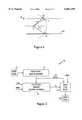
- FIG. 1is a diagram of an arcuate scanner of a tape drive, operating in accordance with an embodiment of the present invention.
- FIG. 2is front view of the arcuate scanner head assembly, of the scanner of FIG. 1, showing the angular relationship of the read and write heads and the passage of a tape past the head assembly.
- FIG. 3is a diagram of the format of information recorded on the tape, when viewed through the tape toward the planar surface end of the arcuate scanner head assembly in FIG. 2.
- FIG. 4is a simplified diagram of the format and the geometric relationship thereof to a read head and a write head.
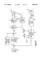
- FIG. 5is a functional/logic diagram of the control of a write operation in accord with a first aspect of the invention.
- FIG. 6is an exaggerated representation of vertical variations in track placement.
- FIG. 7provides a simplified illustration of the geometrical relationship of the arcuate scanner head assembly to the tape format from a side view, helpful in explaining another aspect of the invention.
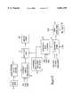
- FIG. 8is a functional/logic diagram of the control of a write operation in accord with another aspect of the invention.
- FIG. 9is a functional/logic diagram of an exemplary embodiment of the tilt angle control and write commutation control in accord with the present invention.
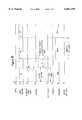
- FIG. 10is a timing diagram helpful in understanding operation of the system when controlled in the manner illustrated in FIG. 9.
- FIG. 1depicts a perspective view of an arcuate scanner head assembly (ASHA) 10 which writes and reads a sequence of arcuate tracks on a recording tape.
- the scanner 10has a drum 12 with an end face 14 at which a plurality of read and write transducers are mounted on support blocks 16.
- a magnetic transducer 15is mounted at the forward tip of each support block 16.
- the drum 12is rotated by a rotatable shaft 20 which is mounted for rotation in a motor/bearing assembly, generally indicated by reference numeral 22. Electrical signals are transferred to and from the transducers on the drum 12 by a conventional rotary transformer assembly having a rotary piece and a stator piece (not visible in the illustrated view).
- the drum 12(with the rotor) is fixed to rotate with the shaft 20.
- the housing 24 and statorare stationary with respect to the shaft 20. As the shaft 20 rotates together with the rotor and drum 12, electrical signals are written to and read from arcuate tracks on the recording tape by a signal path which includes the electromagnetic flux couplings between the rotor and stator.
- the housing 24is essentially cylindrical and encloses the structure providing rotational power to the shaft 20.
- the windings of the statorconnect to wiring pads, one of which is shown as reference numeral 26 on the outer surface of the motor/bearing housing 24.
- the wiring pads 26provide electrical connection through wiring to circuit elements.
- Sensors 28 and 30are also mounted to the housing 24 and provide, respectively, an index signal and a shaft rotational speed signal for each full rotation of the shaft 20.
- the first type of anglerelates to various rotational angles, i.e. of the various scanner heads, about the central axis of the arcuate scanner head assembly. Commutation functions are controlled as a function of the rotational angle relative to the index.
- the other critical angleis the tilt angle of the arcuate scanner head assembly. The tilt angle affects the alignment of the scanner with the tape.
- the scanner 10is positioned at a recording location so that the planar end face 14 of the drum 12 faces a tape on which a sequence of arcuate tracks is to be written or read.
- the end face 14is adjusted with respect to the edges of the tape by pivoting the housing 24, and with it the drum 12, about a pivot axis 32.
- the tapemoves past the end face 14 in a direction indicated by arrow 42 and the drum 12 rotates in the direction of arrow 44.
- a tilt motorcontrols the angular tilting of the scanner 10 with respect to the tape.
- the tilt motorincludes a stationary bracket 34 that carries on its rear portion a conventional voice coil 36 with an open center.
- a U-shaped bracket 38is affixed to the rear end of the motor/bearing housing 24 by another U-shaped bracket (not illustrated).
- the U-shaped bracket 38has one leg which is received in the center of the voice coil 36 and another leg to which a permanent magnet 40 is attached.
- Current through the voice coil 36sets up a magnetic field in its open center which is conducted in the U-shaped bracket 36 to the permanent magnet 40.
- An electromotive forceis exerted on the U-shape bracket 36 and its attached magnet 40 having a magnitude determined by the magnitude of the field induced in the coil 36.
- the scanner 10pivots above the pivot axis 32 by an angular amount that depends upon the relative strengths of the voice coil 36 field and the field of the permanent magnet 40, thereby selectively positioning the axis of rotation on which the shaft 20
- Alternative embodiments of the present inventionprovide other tilt mechanisms, such as a servo motor, or oppositely directed magnetic coils, as appreciated by one of ordinary skill in the art.
- the present inventionis not limited to controlling the tilting of the scanner to control the pointing of the scanner at the recording tape.
- Other embodiments of the inventionprovide other methods of controlling the pointing position of the scanner head relative to the tape. These include controlling the elevation of the scanner with an elevator mechanism, or providing a side swing mechanism for the scanner, as one of ordinary skill in the art will appreciate.
- FIG. 2is a view through a tape at the reading location towards the planar end face of the ASHA scanner drum.
- transducersmounted with their active surfaces extending slightly through a plane at the end face of the drum.
- W 0 , W 1 , W 2 and W 3the active surfaces of the drum.
- W 0 , W 1 , W 2 and W 3the active surfaces of the drum.
- R 0 , R 1 , R 2 and R 3there are four read transducers identified as R 0 , R 1 , R 2 and R 3 .
- Identical subscriptsidentify write/read transducer pairs in which the track written by transducer W 1 is later read by transducer R 1 .
- the write transducersare accurately spaced on the drum by 90° in the order in which they write tracks on the tape, which is W 0 , W 1 , W 2 and W 3 .
- the read transducersare spaced from each other by 90°, but are spaced from adjacent write transducers by 45°.
- read transducer R 1is displaced by 135° in the direction opposite the scanner rotation direction from write transducer W 1 .
- the sequence traced across the tape from edge to edge when the scanner rotates in the direction indicated in FIG. 2is: W 0 , R 3 , W 1 , R 0 , W 2 , R 1 , W 3 , R 2 .
- Write heads W 0 and W 2are oriented to write at a first azimuth angle on the tape, and read heads R 0 and R 2 read information recorded at the first azimuth angle.
- Write heads W 1 and W 3are oriented to write at a second azimuth angle on the tape, and read heads R 1 and R 3 read information recorded at the second azimuth angle.
- the write transducerswhen energized, will trace a sequence of contiguous recorded arcuate tracks with alternating azimuthal orientation. Similarly, the read heads sense recorded information from a sequence of arcuate tracks with alternating azimuthal orientation.
- FIG. 3shows the preferred format of the information on the developed tape in somewhat simplified form, as viewed through the tape looking towards the end face of the ASHA scanner drum in FIG. 2. It should also be noted that the various regions on the tape are not drawn to scale.
- the ⁇ TRIBO ⁇ interface standardspecifies a region along the top edge T of the tape as a guard band.
- a similar guard bandextends along the lower edge L of the tape.
- the top guard bandtypically is 15 mils wide, and the lower guard band typically is 10 mils wide.
- Each TRIBO guard bandextends for the full length of the tape. The arcuate scanner type data recording system will not write data in the guard bands.
- each guard bandis a magnetic stripe, designated an LS1 stripe.
- the manufacturerdeeply records the LS1 stripes along the entire length of the tape.
- the present inventionutilizes the lower LS1 stripe as a reference point.
- the upper LS1 stripeis not strictly necessary for the present invention, but its inclusion is preferred.
- the recorded sections of the tapeare spaced from the upper and lower guard bands and LS1 stripes by a specified distance, e.g. 1.0 mils.
- the actual data tracksare bounded by a top servo region and a lower servo region. Within these regions bursts A and B of servo frequency signals are recorded at predetermined locations.
- the scannerwrites predetermined amounts of erase signals before and after the respective servo bursts.
- a predetermined read headpartially overlaps data tracks in such a manner that it detects differing predetermined amounts of the A and B servo bursts during different time windows.
- the scanner systemuses comparisons of the detected amplitudes of the various A and B servo bursts as a servo control, e.g. for servo control of tape speed and/or ASHA tilt angle.
- all timing and orientation functions for servo control, data read commutation, and data write samplingare based on detection of the lower LS1 stripe and various known positional relationships between the ASHA components.
- the recorded information on the tapeforms arcs.
- the chord lengthbecomes a known value.
- the tapeis typically about 247 mils wide.
- the top guard bandis 15 mils
- the lower guard bandis 10 mils
- the desired spacing from the top guard bandis 1 mil
- the desired spacing from the lower guard bandis 1 mil.
- the chord lengththerefore should be about 220 mils.
- center line Cpasses through the center of the chord length of each recorded arc. Because of the differences in the guard band dimension, the center line C does not coincide with the physical center line of the tape.
- the chord lengthis 220 mils.
- the center of the chordis 110 mils from either end of the arc, or approximately 111 mils above the lower LS1 stripe.
- each write headis activated a predetermined period T 0 after a read head bearing a known angular relationship to the write head crosses the lower LS1 stripe.
- the read head R 1crosses the tape followed by the write head W 3 .
- the crossing of the read head R 1 over the LS1 stripe along the lower guard bandproduces a pulse output from that head.
- the write head W 3is offset by a known angle ⁇ from the read head R 1 , for example by approximately 45° in the ASHA embodiment illustrated in FIG. 2. This angle will vary slightly from one head assembly to another, but for a particular head assembly, this angle will remain constant for the entire useful life of the head-assembly.
- a microcontrollercan calculate a transit delay T 0 required for the write head W 3 to travel from the position shown in FIG. 4 (when the read head R 1 crosses the lower LS1 stripe) until the write head W 3 reaches the point X on the tape at which that head should begin a writing operation.
- the microcontrollertherefore activates the write head W 3 after a delay of T 0 following the detection of the lower LS1 stripe by the read head R 1 .
- FIG. 5is a simplified functional block diagram of the control loop 50 for controlling the write head commutation.
- the read head R 1supplies a detection signal to stripe detection logic and filter circuitry 51.
- the stripe detection logic and circuitry 51produces a pulse signal in response to the passage of the read head R 1 over the magnetized lower LS1 stripe. If two similar LS1 stripes are provided on the tape, e.g. upper and lower stripes as in FIG. 3, then the logic and circuitry 51 will differentiate between the two, for example based on a timing or sequence analysis.
- the stripe detection logic and circuitry 51supplies the LS1 detection pulse signal to a microcontroller (not shown in detail). Within the microcontroller, a microcode process is running to count position pulses relative to index to identify the LS1 position relative to the index. This microcode routine appears at reference numeral 53 in FIG. 5.
- the stripe detection logic and circuitry 51supplies the LS1 detection pulse signal to the position counter routine 53, and the routine 53 calculates a delay time T 0 for the transit of the next write head W 3 to the point X for the start of its write operation, as outlined above relative to FIG. 4.
- the LS1 position counter routine 53produces a clock count value representing the number of clock pulses equal to the necessary time delay T 0 .
- the stripe detection logic and circuitry 51also supplies the LS1 detection pulse signal to write control logic 53.
- the write control logic 55may be a separate circuit or another microcode routine running on the microcontroller.
- the LS1 position counter routine 53supplies the clock count.value representing the number of clock pulses equal to the necessary time delay T 0 to the write control logic 55.
- the write control logic 55counts the specified number of clock pulses equal to the necessary time delay T 0 following the LS1 detection pulse, and at that time, activates the write head W 3 to initiate its write operation.
- the microcontrolleralso provides servo signals, erase signals and data to the write head to write data on the tape in the sequence required to achieve the format shown in FIG. 3. All of the write sequence operations are referenced back to the pulse detected when the read head R 1 crossed over the lower LS1 stripe.
- read head signalsare similarly timed in relation to the LS1 stripe detection. Since the angle between read heads is known (FIG. 2), the signal processing circuity is activated to begin sampling and interpreting signals from the next read head when that read head reaches the appropriate position X over the tape.
- the control functionalityis virtually identical to that used to activate the operation of the write head W 3 discussed above.
- various timing windowsare defined by the microcode of the microcontroller. These windows for each read head are referenced to an earlier crossing of a read head over the lower LS1 stripe.
- the servo burst A Tis written in a particular section of the tape, and bounded by specified amounts of erase signal (E).
- the third read head R 3is located at an angle of 90° with regard to the second read head R 2 .
- the circuitry responsive to the signals from the third read head R 3are time indexed to the pulse signal indicating the passage of head R 2 over the lower LS1 stripe.
- a time windowis defined with reference to that LS1 crossing when the circuitry will sample for the A T servo burst. Similar time windows are defined for detecting the second top servo burst B T , the bottom server bursts A B , B B and various format timing blocks within the data tracks.
- the tilt angle of the ASHAis also referenced to the lower LS1 stripe.
- the write operation referenced to that stripewill also wander.
- FIG. 6provides a somewhat exaggerated representation of a developed tape showing the wander of the lower LS1 stripe and the corresponding variations in placement of the formatted information. As shown, at locations where the lower LS1 strip is slightly higher in relation to the bottom edge of the tape, the write head will place the written format information IF 1 at a correspondingly higher position on the tape. At such locations, the chord center C c is higher.
- the write headwill place the written format information IF 2 at a correspondingly lower position on the tape.
- the chord center C cis lower.
- the line formed by the centers of the arcs (C in FIG. 3)is no longer straight, instead the center line wanders in the same manner as the lower LS1 stripe. At any given point, however, the distance from LS1 to the center line C remains approximately constant.
- FIG. 7provides a lateral view of the relevant geometry.
- the ASHAis effectively aimed by adjusting the tilt angle ⁇ about the axis 32, as discussed above relative to FIG. 1.
- the tilt angleis servo controlled in response to detection of the lower LS1 stripe by one of the read heads, such as read head R 1 .
- the tilt angle ⁇is adjusted in response to detection of the lower LS1 stripe to keep the angle ⁇ 1 of the read head from the axis C d constant.
- FIG. 4can be referenced to explain how this operation works.
- the angle ⁇ 2 between the center of rotation C d and the point at which a specific read head, e.g. R 1 , crosses the lower LS1 stripeis a known constant.
- the intentis to align the center of rotation C d of the ASHA with the center of the information arc (i.e. at a particular point on the wandering center line C).
- the relationship of the lower LS1 stripe to the information arcis known.
- the angle ⁇ 2represents the angle of head rotation from the center of the information arc to the crossing of LS1.
- this anglecorresponds to one half the arc angle plus some small amount for the spacing between the arc and the lower LS1 stripe.
- variations in the angle ⁇ 2e.g. measured with reference to the index 28
- FIG. 8is a simplified functional block diagram of the control loop for controlling the tilt angle.
- this drawingshows only one read head, but it will be readily apparent that similar processing occurs with respect to other heads on the ASHA.
- the ASHA 10has a tilt motor 300, for example, comprising the elements 34, 36, 38 and 40 of FIG. 1.
- the tilt motor 300responds to signals from a current mode amplifier to adjust the tilt angle of the ASHA 10.
- An analog position loop 61provides a control current signal to the current mode amplifier 60.
- An optical position sensor 63detects the actual position of the ASHA produced by the tilt motor 300 and supplies a position sensor signal to the analog position loop 61.
- the analog position loop 61also is responsive to a position error signal (PES) produced in accord with the second aspect of the present invention. More specifically, the position error signal represents an error in the angle ⁇ 2 shown in FIG. 4.
- PESposition error signal
- the tilt control of the present inventionoperates during both read and write operations to maintain proper alignment. Consider first a write operation.
- one of the read headscrosses the lower LS1 stripe, e.g. read head R 1 .
- the read head R 1supplies signals to stripe detection logic and associated circuitry 65.
- the stripe detection logic and circuitry 65produces a pulse signal in response to the passage of the read head R 1 over the magnetized lower LS1 stripe. If two similar LS1 stripes are provided on the tape, e.g. upper and lower stripes as in FIG. 3, then the logic and circuitry 65 will differentiate between the two, for example based on a timing or sequence analysis.
- the stripe detection logic and circuitry 65supplies the LS1 pulse signal to a microcontroller (not shown in detail). Within the microcontroller, a microcode process is running to count position pulses relative to index 28 to identify the LS1 position relative to the index.
- This microcode routineappears at 67 in FIG. 8 and is similar to the routine 53 discussed above with regard to FIG. 5.
- the LS1 position routine 67receives the LS1 detection pulse, the tachometer (revolutions per minute) reading from the sensor 30, the ASHA index position from the sensor 28 (one per revolution) and a clock signal. From that information, the LS1 position routine 67 produces coarse and fine count values for the position of the LS1 crossing relative to the index.
- the count values for the current positionare applied to the negative input of a summation circuit 69.
- the summation circuit 69also receives coarse and fine values for a reference angle 68 for the LS1 crossing relative to the index.
- the summation circuitproduces a difference or error signal representing the difference between the measured LS1 position relative to index and the reference LS1 position relative to index.
- the summation circuit 69supplies this error signal to another microcode routine 71 of the microcontroller. This routine is the LS1 tilt servo loop control microcode.
- the microcode routine 71produces an analog position error signal (D/A converter not shown) which is summed with a reference analog position signal in a second summation circuit 73. The result of this summation goes to the analog position loop 61 as the position error signal (PES).
- PESposition error signal
- the loop control of FIG. 8adjusts the current applied to the tilt motor 300 to keep the LS1 angle ⁇ 2 constant as measured with respect to the angular rotation index of the ASHA.
- the tracksall end a specified distance (e.g. 1 mil) above the lower LS1 stripe.
- the same loopoperates to control the tilt angle during the reading operation.
- the tilt tracking loopcan also be fine tuned to exit and enter tracks at the center of the tracks.
- the LS1 tilt servois modulated based on a servo loop detection of the A and B servo pulses.
- the head commutation timing and the tilt angle control described aboveoccur as part of the ongoing control operations of the ASHA during each and every read cycle and write cycle executed through the ASHA.
- the activation of the write heads, the interpretation of the read head outputs and the tilt angle alignment of the ASHA with respect to the center of each data arcall are referenced to a common point on the tape, the crossing point of a read head over the lower LS1 stripe.
- FIG. 9depicts the most exemplary embodiment of the control circuitry in accord with the present invention.
- the embodiment of FIG. 9differs from that of FIGS. 5 and 8 in that it provides both tilt angle control and write commutation control in one circuit.
- the control circuit of FIG. 9references the commutation functions to an estimated lower LS1 detection event, rather than directly to an actual lower LS1 detection. Occasionally, the detection circuitry will miss the lower LS1 stripe detection. The tilt angle control elements will maintain the tilt angle at the last value for that angle. The lower LS1 estimation will still provide the necessary commutation timing reference.
- FIG. 9Several of the components shown in FIG. 9 are the same as components appearing in the earlier drawings, and those elements are indexed by the same reference numerals used in the earlier drawings.
- FIG. 10illustrates the timing of events and signals during control in accord with FIG. 9, and the following description will refer to both FIG. 9 and FIG. 10.
- the processinglogically begins with an S1 signal indicating detection of the index.
- the second line H in FIG. 10shows the times during which the various heads pass the tape.
- the read head R 1supplies a detection signal to stripe detection logic and filter circuitry 51. Passage of the head over the lower LS1 stripe produces an analog pulse waveform as shown at S2 in FIG. 2.
- the stripe detection logic and circuitry 51converts that analog impulse into a digital level type pulse signal (S3). As shown, the timing of the pulse signal (S3) coincides with the passage of the read head R 1 over the magnetized lower LS1 stripe.
- the stripe detection logic and circuitry 51supplies the lower LS1 detection pulse signal to a microcontroller (not shown in detail).
- a microcode process 67is running to count position pulses relative to index 28 to identify the lower LS1 position relative to the index.
- the LS1 position routine 67receives the lower LS1 detection pulse, the tachometer (revolutions per minute) reading from the sensor 30, the ASHA index position from the sensor 28 (one per revolution) and a clock signal. From that information, the LS1 position routine 67 produces coarse and fine count values for the position of the lower LS1 crossing relative to the index.
- the coarse and fine count values for the position of the lower LS1 crossing relative to the index and the coarse and fine count values for the LS1 reference position 68go to an ASHA LS1 tilt servo circuit 91.
- the circuit 91controls the tilt motor 300 and generally comprises the elements shown in FIG. 8 not reproduced in FIG. 9, e.g. the summation circuit 69, the loop control 71, the summation circuit 73, the nominal caged tilt value microcode, the position loop 61, the amplifier 60 and the position sensor 63.
- the ASHA LS1 tilt servo circuit 91controls the tilt motor 300 to maintain a constant rotational angle of the head R1 with respect to crossing of the lower LS1 stripe, when measured relative to the index, in the same manner as discussed above in detail relative to the embodiment of FIG. 8.
- the coarse and fine count values for the LS1 reference position 68also go to a pulse signal generator 93.
- the generator 93generates a pulse at a time after index estimated to coincide with crossing of the lower LS1 stripe by the read head R 1 as shown at S4 in FIG. 10. If the tilt angle is controlled as discussed above to keep the rotational reference angle constant, then the estimated lower LS1 pulse (S4) should coincide with the actual lower LS1 detection pulse (S3), as shown by comparison of those signals in FIG. 10.
- the pulse output by the generator 93is not dependent directly on actual lower LS1 stripe detection. If the system misses the lower LS1 stripe for a cycle or two, for some reason, the pulse generator 93 continues to output the pulse at the appropriate time after the index signal; and the write control logic 55 continues to activate the write heads to write the various forms of information on the recording tape.
- the estimated LS1 pulse generator 93outputs the pulse (S4) to a timer circuit 95.
- the timer circuit 95receives an ASHA speed or tachometer signal (revolutions per minute) and the clock signal.
- the timer circuit 95also receives an angle count (R 1 to W 3 ) representing the transit time T 0 for the head W 3 to travel from its position when the head R 1 crosses the lower LS1 stripe to the position at which that write head should begin writing.
- the timer circuit 95receives the angle count value from an appropriate microcode routine running in the microcontroller. This routine may be responsive to actual lower LS1 crossing detections, as in the earlier embodiment.
- the timer 95utilizes the last T 0 count value it received. Therefore the operation of the timer 95 is not interrupted by a temporary loss of detection of the lower LS1 stripe crossing.
- the write control logic 97passes data and other signals to the write head in response to the pulse signal (S5) from the timer circuit 95.
- Line S6 in FIG. 10shows the write interval initiated by the pulse S5.
- the logic circuit 97terminates the write operation, as shown by the pulse signal S7 in FIG. 10.
- the various sequencing operations within one write cyclealso are controlled in reference to the lower LS1 stripe.
- the tilt angleis controlled directly in response to the lower LS1 stripe detection to maintain a constant reference angle between the index and the point of rotation of the read head to detect that stripe.
- the LS1 detectioncoincides with the estimated LS1 pulse.
- the actual timing functions within the write sequenceare controlled in response to the estimated LS1 detection pulse.
- the timing functions relevant to read operationscan be controlled in a similar manner.
Landscapes
- Adjustment Of The Magnetic Head Position Track Following On Tapes (AREA)
Abstract
Description
Claims (8)
Priority Applications (1)
| Application Number | Priority Date | Filing Date | Title |
|---|---|---|---|
| US09/398,426US6061199A (en) | 1995-11-13 | 1999-09-17 | Method and arrangement for servoing and formatting magnetic recording tape |
Applications Claiming Priority (3)
| Application Number | Priority Date | Filing Date | Title |
|---|---|---|---|
| US08/557,772US5796537A (en) | 1995-11-13 | 1995-11-13 | Method and arrangement for servoing and formatting magnetic recording tape |
| US09/071,696US6031681A (en) | 1995-11-13 | 1998-05-01 | Method and arrangement for servoing and formatting magnetic recording tape |
| US09/398,426US6061199A (en) | 1995-11-13 | 1999-09-17 | Method and arrangement for servoing and formatting magnetic recording tape |
Related Parent Applications (1)
| Application Number | Title | Priority Date | Filing Date |
|---|---|---|---|
| US09/071,696DivisionUS6031681A (en) | 1995-11-13 | 1998-05-01 | Method and arrangement for servoing and formatting magnetic recording tape |
Publications (1)
| Publication Number | Publication Date |
|---|---|
| US6061199Atrue US6061199A (en) | 2000-05-09 |
Family
ID=24226825
Family Applications (3)
| Application Number | Title | Priority Date | Filing Date |
|---|---|---|---|
| US08/557,772Expired - Fee RelatedUS5796537A (en) | 1995-11-13 | 1995-11-13 | Method and arrangement for servoing and formatting magnetic recording tape |
| US09/071,696Expired - LifetimeUS6031681A (en) | 1995-11-13 | 1998-05-01 | Method and arrangement for servoing and formatting magnetic recording tape |
| US09/398,426Expired - LifetimeUS6061199A (en) | 1995-11-13 | 1999-09-17 | Method and arrangement for servoing and formatting magnetic recording tape |
Family Applications Before (2)
| Application Number | Title | Priority Date | Filing Date |
|---|---|---|---|
| US08/557,772Expired - Fee RelatedUS5796537A (en) | 1995-11-13 | 1995-11-13 | Method and arrangement for servoing and formatting magnetic recording tape |
| US09/071,696Expired - LifetimeUS6031681A (en) | 1995-11-13 | 1998-05-01 | Method and arrangement for servoing and formatting magnetic recording tape |
Country Status (1)
| Country | Link |
|---|---|
| US (3) | US5796537A (en) |
Cited By (17)
| Publication number | Priority date | Publication date | Assignee | Title |
|---|---|---|---|---|
| US6700729B1 (en) | 2000-10-17 | 2004-03-02 | Hewlett-Packard Development Company | Alignment marks for tape head positioning |
| US20040218304A1 (en)* | 2002-12-19 | 2004-11-04 | Turguy Goker | Method and apparatus for written-in tracking error compensation for linear tape drives |
| US20050083601A1 (en)* | 2003-10-20 | 2005-04-21 | Faramarz Mahnad | Servo methods and systems using existing data structures and optical masks |
| US20050083600A1 (en)* | 2003-10-20 | 2005-04-21 | Faramarz Mahnad | Methods and systems for magnetic recording |
| US20050088776A1 (en)* | 2003-10-20 | 2005-04-28 | Saliba George A. | Diffractive position sensors and control systems |
| US20050088770A1 (en)* | 2003-10-20 | 2005-04-28 | George A. Saliba | Electromagnetic void-sensing probes and position control systems |
| US20050094308A1 (en)* | 2003-10-20 | 2005-05-05 | Faramarz Mahnad | Servo methods and systems using masked medium edge position sensors |
| US20050270687A1 (en)* | 2004-06-04 | 2005-12-08 | James Zweighaft | Dual source tracking servo systems and associated methods |
| US20060103968A1 (en)* | 2004-11-12 | 2006-05-18 | Jurneke Joe K | Dynamic skew compensation systems and associated methods |
| US7102845B2 (en) | 2003-10-20 | 2006-09-05 | Quantum Corporation | Servo methods and systems using existing data structures and medium edge position |
| US20060209450A1 (en)* | 2005-03-18 | 2006-09-21 | Quantum Corporation | Auto-servo tape system and associated recording head |
| US20080266705A1 (en)* | 2007-04-25 | 2008-10-30 | Quantum Corporation | Servo error detection and compensation utilizing virtual data tracking servo methods |
| US8780682B2 (en) | 2012-11-07 | 2014-07-15 | Oracle International Corporation | Rotary head data storage and retrieval system and method for data erasure |
| US8793713B2 (en) | 2012-11-07 | 2014-07-29 | Oracle International Corporation | Rotary head data storage and retrieval system and method with tape medium having transverse primary data tracks and longitudinal secondary data track |
| US8869179B2 (en)* | 2011-06-17 | 2014-10-21 | Oracle International Corporation | Rotary head data storage and retrieval system and method |
| US8897113B2 (en) | 2012-11-07 | 2014-11-25 | Oracle International Corporation | Rotary head data storage and retrieval system and method for data verification |
| US9324347B2 (en) | 2012-09-19 | 2016-04-26 | Oracle International Corporation | Apparatus and method for controlling tape movement in a rotary head data storage system and retrieval system |
Families Citing this family (5)
| Publication number | Priority date | Publication date | Assignee | Title |
|---|---|---|---|---|
| US5986846A (en)* | 1997-07-09 | 1999-11-16 | Seagate Technology, Inc. | Methods and apparatus for track centering an arcuate scanner head assembly |
| US6101061A (en)* | 1997-10-01 | 2000-08-08 | Seagate Technology, Inc. | Methods and apparatus for calibration of a rotating scanner to a plurality of data track groups recorded on a tape |
| US6072653A (en) | 1997-10-01 | 2000-06-06 | Seagate Technology, Inc. | Methods and apparatus for calibration of a rotating scanner to a track recorded on a tape |
| US20020104882A1 (en)* | 1998-04-09 | 2002-08-08 | Jeffrey F. Liu | Optical data card reader system |
| JP3649587B2 (en)* | 1998-05-25 | 2005-05-18 | アルプス電気株式会社 | Rotating head device |
Citations (29)
| Publication number | Priority date | Publication date | Assignee | Title |
|---|---|---|---|---|
| US2750449A (en)* | 1951-11-07 | 1956-06-12 | Soundscriber Corp | Long playing magnetic tape recorder |
| US2772328A (en)* | 1952-04-28 | 1956-11-27 | Soundscriber Corp | Automatic synchronization apparatus for long-time transverse magnetic sound recorder and reproducer |
| US2900444A (en)* | 1953-01-12 | 1959-08-18 | Armour Res Found | Means for recording and reproducing video signals |
| US2924668A (en)* | 1956-01-25 | 1960-02-09 | Tdk Electronics Co Ltd | Magnetic recording and reading apparatus |
| US3320371A (en)* | 1963-01-08 | 1967-05-16 | Bach Auricon Inc | Video tape recording apparatus utilizing transversely scanning erase and record heads |
| US3351718A (en)* | 1954-05-04 | 1967-11-07 | Jr Thomas A Banning | Transverse scan magnetic recording using a cathode ray tube recording means |
| US3790755A (en)* | 1961-12-08 | 1974-02-05 | D Silverman | High density information system using multiple strips |
| US4112472A (en)* | 1977-02-28 | 1978-09-05 | International Business Machines Corporation | Longitudinal scan, cam shaped, turntable rotor for magnetic recording |
| US4139871A (en)* | 1975-11-24 | 1979-02-13 | Nippon Hoso Kyokai | Eight-head magnetic video tape recording and reproducing apparatus with rotary transformer |
| JPS5963913A (en)* | 1982-10-05 | 1984-04-11 | 松下電工株式会社 | Indoor wiring system |
| US4525754A (en)* | 1983-04-06 | 1985-06-25 | Ampex Corporation | System and method for synchronization of rotary head magnetic recording/reproducing devices |
| US4636886A (en)* | 1984-08-02 | 1987-01-13 | Magnetic Peripherals Inc. | Rotary head recording system |
| US4647993A (en)* | 1984-08-02 | 1987-03-03 | Magnetic Peripherals Inc. | Rotary head recording system |
| JPS62169716A (en)* | 1986-01-23 | 1987-07-25 | Pola Chem Ind Inc | Cosmetic |
| US4731681A (en)* | 1985-03-23 | 1988-03-15 | Victor Company Of Japan, Limited | Vertical magnetic recording and playback apparatus |
| US5060104A (en)* | 1989-07-28 | 1991-10-22 | Kabushiki Kaisha Toshiba | Rotary head device with six head units |
| WO1993026005A2 (en)* | 1992-06-12 | 1993-12-23 | Minnesota Mining And Manufacturing Company | Arcuate scanning tape drive |
| US5339207A (en)* | 1992-03-10 | 1994-08-16 | Nec Corporation | Servo system for providing increased recording density and improved operation of the AGC circuitry |
| US5345345A (en)* | 1990-03-06 | 1994-09-06 | Alps Electric Co., Ltd. | Rotary head type magnetic recording/reproducing unit |
| US5371638A (en)* | 1992-06-24 | 1994-12-06 | Digital Equipment Corporation | Servo method and apparatus for very high track density magnetic recording by adjusting head position based on servo information read from adjacent track |
| US5381277A (en)* | 1992-07-31 | 1995-01-10 | Sgs-Thompson Microelectronics S.A. | Method and apparatus for decreasing a transition time of a read head from a write mode to a read mode |
| US5396376A (en)* | 1992-03-23 | 1995-03-07 | Conner Peripherals, Inc. | Multi-track embedded servo recording format and method |
| WO1995006940A1 (en)* | 1993-08-30 | 1995-03-09 | Conner Peripherals, Inc. | Arcuate scan tape drive |
| US5412517A (en)* | 1992-11-11 | 1995-05-02 | Sony Corporation | Magnetic tape recording/playback device with playback monitoring |
| US5446601A (en)* | 1993-03-08 | 1995-08-29 | International Business Machines Corporation | Read/write circuit for minimizing recovery time |
| US5448430A (en)* | 1993-08-05 | 1995-09-05 | International Business Machines Corporation | Track following servo demodulation |
| US5453887A (en)* | 1987-01-13 | 1995-09-26 | Canon Denshi Kabushiki Kaisha | Head tracking servo pattern |
| WO1996000437A1 (en)* | 1994-06-27 | 1996-01-04 | Minnesota Mining And Manufacturing Company | Arcuate scanning head assembly and tape cartridge therefor |
| US5488525A (en)* | 1994-08-18 | 1996-01-30 | International Business Machines Corporation | Decoupled magnetic head assembly for quarter-inch tape |
- 1995
- 1995-11-13USUS08/557,772patent/US5796537A/ennot_activeExpired - Fee Related
- 1998
- 1998-05-01USUS09/071,696patent/US6031681A/ennot_activeExpired - Lifetime
- 1999
- 1999-09-17USUS09/398,426patent/US6061199A/ennot_activeExpired - Lifetime
Patent Citations (29)
| Publication number | Priority date | Publication date | Assignee | Title |
|---|---|---|---|---|
| US2750449A (en)* | 1951-11-07 | 1956-06-12 | Soundscriber Corp | Long playing magnetic tape recorder |
| US2772328A (en)* | 1952-04-28 | 1956-11-27 | Soundscriber Corp | Automatic synchronization apparatus for long-time transverse magnetic sound recorder and reproducer |
| US2900444A (en)* | 1953-01-12 | 1959-08-18 | Armour Res Found | Means for recording and reproducing video signals |
| US3351718A (en)* | 1954-05-04 | 1967-11-07 | Jr Thomas A Banning | Transverse scan magnetic recording using a cathode ray tube recording means |
| US2924668A (en)* | 1956-01-25 | 1960-02-09 | Tdk Electronics Co Ltd | Magnetic recording and reading apparatus |
| US3790755A (en)* | 1961-12-08 | 1974-02-05 | D Silverman | High density information system using multiple strips |
| US3320371A (en)* | 1963-01-08 | 1967-05-16 | Bach Auricon Inc | Video tape recording apparatus utilizing transversely scanning erase and record heads |
| US4139871A (en)* | 1975-11-24 | 1979-02-13 | Nippon Hoso Kyokai | Eight-head magnetic video tape recording and reproducing apparatus with rotary transformer |
| US4112472A (en)* | 1977-02-28 | 1978-09-05 | International Business Machines Corporation | Longitudinal scan, cam shaped, turntable rotor for magnetic recording |
| JPS5963913A (en)* | 1982-10-05 | 1984-04-11 | 松下電工株式会社 | Indoor wiring system |
| US4525754A (en)* | 1983-04-06 | 1985-06-25 | Ampex Corporation | System and method for synchronization of rotary head magnetic recording/reproducing devices |
| US4636886A (en)* | 1984-08-02 | 1987-01-13 | Magnetic Peripherals Inc. | Rotary head recording system |
| US4647993A (en)* | 1984-08-02 | 1987-03-03 | Magnetic Peripherals Inc. | Rotary head recording system |
| US4731681A (en)* | 1985-03-23 | 1988-03-15 | Victor Company Of Japan, Limited | Vertical magnetic recording and playback apparatus |
| JPS62169716A (en)* | 1986-01-23 | 1987-07-25 | Pola Chem Ind Inc | Cosmetic |
| US5453887A (en)* | 1987-01-13 | 1995-09-26 | Canon Denshi Kabushiki Kaisha | Head tracking servo pattern |
| US5060104A (en)* | 1989-07-28 | 1991-10-22 | Kabushiki Kaisha Toshiba | Rotary head device with six head units |
| US5345345A (en)* | 1990-03-06 | 1994-09-06 | Alps Electric Co., Ltd. | Rotary head type magnetic recording/reproducing unit |
| US5339207A (en)* | 1992-03-10 | 1994-08-16 | Nec Corporation | Servo system for providing increased recording density and improved operation of the AGC circuitry |
| US5396376A (en)* | 1992-03-23 | 1995-03-07 | Conner Peripherals, Inc. | Multi-track embedded servo recording format and method |
| WO1993026005A2 (en)* | 1992-06-12 | 1993-12-23 | Minnesota Mining And Manufacturing Company | Arcuate scanning tape drive |
| US5371638A (en)* | 1992-06-24 | 1994-12-06 | Digital Equipment Corporation | Servo method and apparatus for very high track density magnetic recording by adjusting head position based on servo information read from adjacent track |
| US5381277A (en)* | 1992-07-31 | 1995-01-10 | Sgs-Thompson Microelectronics S.A. | Method and apparatus for decreasing a transition time of a read head from a write mode to a read mode |
| US5412517A (en)* | 1992-11-11 | 1995-05-02 | Sony Corporation | Magnetic tape recording/playback device with playback monitoring |
| US5446601A (en)* | 1993-03-08 | 1995-08-29 | International Business Machines Corporation | Read/write circuit for minimizing recovery time |
| US5448430A (en)* | 1993-08-05 | 1995-09-05 | International Business Machines Corporation | Track following servo demodulation |
| WO1995006940A1 (en)* | 1993-08-30 | 1995-03-09 | Conner Peripherals, Inc. | Arcuate scan tape drive |
| WO1996000437A1 (en)* | 1994-06-27 | 1996-01-04 | Minnesota Mining And Manufacturing Company | Arcuate scanning head assembly and tape cartridge therefor |
| US5488525A (en)* | 1994-08-18 | 1996-01-30 | International Business Machines Corporation | Decoupled magnetic head assembly for quarter-inch tape |
Non-Patent Citations (2)
| Title |
|---|
| "Movable Head/Movable Track Accessory Arrangement", by Lissner, R. W., IBM Technology Disclosure Bulletin, Marcy. 1997. |
| Movable Head/Movable Track Accessory Arrangement , by Lissner, R. W., IBM Technology Disclosure Bulletin, Marcy. 1997.* |
Cited By (28)
| Publication number | Priority date | Publication date | Assignee | Title |
|---|---|---|---|---|
| US6700729B1 (en) | 2000-10-17 | 2004-03-02 | Hewlett-Packard Development Company | Alignment marks for tape head positioning |
| US6943979B2 (en) | 2002-12-19 | 2005-09-13 | Certance, Llc | Method and apparatus for written-in tracking error composition for linear tape drives |
| US20040218304A1 (en)* | 2002-12-19 | 2004-11-04 | Turguy Goker | Method and apparatus for written-in tracking error compensation for linear tape drives |
| US7136255B2 (en) | 2003-10-20 | 2006-11-14 | Quantum Corporation | Servo methods and systems using masked medium edge position sensors |
| US7149050B2 (en) | 2003-10-20 | 2006-12-12 | Quantum Corporation | Diffractive position sensors and control systems |
| US20050088770A1 (en)* | 2003-10-20 | 2005-04-28 | George A. Saliba | Electromagnetic void-sensing probes and position control systems |
| US20050094308A1 (en)* | 2003-10-20 | 2005-05-05 | Faramarz Mahnad | Servo methods and systems using masked medium edge position sensors |
| US20050083600A1 (en)* | 2003-10-20 | 2005-04-21 | Faramarz Mahnad | Methods and systems for magnetic recording |
| US20050088776A1 (en)* | 2003-10-20 | 2005-04-28 | Saliba George A. | Diffractive position sensors and control systems |
| US7139152B2 (en) | 2003-10-20 | 2006-11-21 | Quantum Corporation | Servo methods and systems using existing data structures and optical masks |
| US7085095B2 (en) | 2003-10-20 | 2006-08-01 | Quantum Corporation | Electromagnetic void-sensing probes and position control systems |
| US7102845B2 (en) | 2003-10-20 | 2006-09-05 | Quantum Corporation | Servo methods and systems using existing data structures and medium edge position |
| US20050083601A1 (en)* | 2003-10-20 | 2005-04-21 | Faramarz Mahnad | Servo methods and systems using existing data structures and optical masks |
| US7116514B2 (en) | 2003-10-20 | 2006-10-03 | Quantum Corporation | Methods and systems for magnetic recording |
| US7184233B2 (en) | 2004-06-04 | 2007-02-27 | Quantum Corporation | Dual source tracking servo systems and associated methods |
| US20050270687A1 (en)* | 2004-06-04 | 2005-12-08 | James Zweighaft | Dual source tracking servo systems and associated methods |
| US20060103968A1 (en)* | 2004-11-12 | 2006-05-18 | Jurneke Joe K | Dynamic skew compensation systems and associated methods |
| US7499235B2 (en) | 2005-03-18 | 2009-03-03 | Quantum Corporation | Auto-servo tape system and associated recording head |
| US20080198503A1 (en)* | 2005-03-18 | 2008-08-21 | Quantum Corporation | Auto-servo tape system and associated recording head |
| US20060209450A1 (en)* | 2005-03-18 | 2006-09-21 | Quantum Corporation | Auto-servo tape system and associated recording head |
| US7649707B2 (en) | 2005-03-18 | 2010-01-19 | Quantum Corporation | Auto-servo tape system and associated recording head |
| US20080266705A1 (en)* | 2007-04-25 | 2008-10-30 | Quantum Corporation | Servo error detection and compensation utilizing virtual data tracking servo methods |
| US7826169B2 (en) | 2007-04-25 | 2010-11-02 | Quantum Corporation | Servo error detection and compensation utilizing virtual data tracking servo methods |
| US8869179B2 (en)* | 2011-06-17 | 2014-10-21 | Oracle International Corporation | Rotary head data storage and retrieval system and method |
| US9324347B2 (en) | 2012-09-19 | 2016-04-26 | Oracle International Corporation | Apparatus and method for controlling tape movement in a rotary head data storage system and retrieval system |
| US8780682B2 (en) | 2012-11-07 | 2014-07-15 | Oracle International Corporation | Rotary head data storage and retrieval system and method for data erasure |
| US8793713B2 (en) | 2012-11-07 | 2014-07-29 | Oracle International Corporation | Rotary head data storage and retrieval system and method with tape medium having transverse primary data tracks and longitudinal secondary data track |
| US8897113B2 (en) | 2012-11-07 | 2014-11-25 | Oracle International Corporation | Rotary head data storage and retrieval system and method for data verification |
Also Published As
| Publication number | Publication date |
|---|---|
| US5796537A (en) | 1998-08-18 |
| US6031681A (en) | 2000-02-29 |
Similar Documents
| Publication | Publication Date | Title |
|---|---|---|
| US6061199A (en) | Method and arrangement for servoing and formatting magnetic recording tape | |
| US5847892A (en) | Servoing and formatting magnetic recording tape in an arcuate scanner system | |
| CA2066189C (en) | Servo tracking for helical scan recorder | |
| US4823212A (en) | Sampled servo code format and system for a disc drive | |
| US4530019A (en) | Servo pattern | |
| US4101942A (en) | Track following servo system and track following code | |
| US6130792A (en) | Flat servo bursts for arcuate track scanner | |
| US5969898A (en) | Method and system for reading data that is unreadable by a tape drive | |
| US4120008A (en) | Overlap track servo for dynamic position correction in a rotary-head tape recorder | |
| US5070421A (en) | Magnetic disk system having tracking control using recorded information | |
| US5675447A (en) | Method and arrangement for initiating search for start of data in arcuately recorded data tracks | |
| US5276566A (en) | Recording/reading high density data tracks with backward compatibility | |
| US5091808A (en) | Two-motor servo mechanism system for a magnetic disk drive | |
| US5815337A (en) | Tape drive having an arcuate scanner and a method for calibrating the arcuate scanner | |
| MY101621A (en) | Positioning misaligned disk heads | |
| US5793552A (en) | Method and apparatus for high speed searching in arcuate scan tape drives | |
| KR100281786B1 (en) | Recorder | |
| US5089918A (en) | Magnetic recording and/or reproducing apparatus having single head with two gaps and providing different lead angles in different operating states | |
| KR100275058B1 (en) | Recording/reproducing apparatus | |
| US5986846A (en) | Methods and apparatus for track centering an arcuate scanner head assembly | |
| JP2506648B2 (en) | Magnetic head positioning device | |
| EP0361488B1 (en) | Magnetic disk apparatus having a circuit for detecting the position of servo information recorded on a magnetic disk | |
| JPS62188015A (en) | Servo pattern recording method in magnetic disk device | |
| JPH05225540A (en) | Magnetic recording and reproducing device | |
| JPH10308008A (en) | Tracking servo method for magnetic reproducing apparatus and magnetic reproducing apparatus |
Legal Events
| Date | Code | Title | Description |
|---|---|---|---|
| STCF | Information on status: patent grant | Free format text:PATENTED CASE | |
| AS | Assignment | Owner name:SEAGATE REMOVABLE STORAGE SOLUTIONS LLC, CALIFORNI Free format text:ASSIGNMENT OF ASSIGNORS INTEREST;ASSIGNOR:SEAGATE TECHNOLOGY, INC.;REEL/FRAME:011111/0459 Effective date:20000728 | |
| AS | Assignment | Owner name:CHASE MANHATTAN BANK, AS COLLATERAL AGENT, THE, NE Free format text:SECURITY AGREEMENT;ASSIGNOR:SEAGATE REMOVABLE STORAGE SOLUTIONS LLC;REEL/FRAME:011436/0001 Effective date:20001122 | |
| FPAY | Fee payment | Year of fee payment:4 | |
| FEPP | Fee payment procedure | Free format text:PAYOR NUMBER ASSIGNED (ORIGINAL EVENT CODE: ASPN); ENTITY STATUS OF PATENT OWNER: LARGE ENTITY | |
| AS | Assignment | Owner name:CERTANCE LLC (FORMERLY SEAGATE REMOVABLE STORAGE S Free format text:RELEASE;ASSIGNOR:JPMORGAN CHASE BANK;REEL/FRAME:015918/0321 Effective date:20041101 | |
| AS | Assignment | Owner name:CERTANCE LLC, CALIFORNIA Free format text:ASSIGNMENT OF ASSIGNORS INTEREST;ASSIGNOR:SEAGATE REMOVABLE STORAGE SOLUTIONS, LLC;REEL/FRAME:018260/0302 Effective date:20030401 | |
| AS | Assignment | Owner name:KEYBANK NATIONAL ASSOCIATION, AS ADMINISTRATIVE AG Free format text:INTELLECTUAL PROPERTY SECURITY AGREEMENT (SECOND LIEN);ASSIGNOR:QUANTUM CORPORATION;REEL/FRAME:018268/0475 Effective date:20060822 | |
| AS | Assignment | Owner name:KEYBANK NATIONAL ASSOCIATION, AS ADMINISTRATIVE AG Free format text:INTELLECTUAL PROPERTY SECURITY AGREEMENT (FIRST LIEN);ASSIGNOR:QUANTUM CORPORATION;REEL/FRAME:018303/0336 Effective date:20060822 | |
| AS | Assignment | Owner name:CERTANCE LLC, CALIFORNIA Free format text:CHANGE OF NAME;ASSIGNOR:SEAGATE REMOVABLE STORAGE SOLUTIONS LLC;REEL/FRAME:019529/0409 Effective date:20030407 | |
| AS | Assignment | Owner name:QUANTUM CORPORATION, CALIFORNIA Free format text:TERMINATION OF SECURITY INTEREST IN PATENTS REEL 018269 FRAME 0005 AND REEL 018268 FRAME 0475;ASSIGNOR:KEY BANK, NATIONAL ASSOCIATION;REEL/FRAME:019550/0659 Effective date:20070712 Owner name:QUANTUM CORPORATION,CALIFORNIA Free format text:TERMINATION OF SECURITY INTEREST IN PATENTS REEL 018269 FRAME 0005 AND REEL 018268 FRAME 0475;ASSIGNOR:KEY BANK, NATIONAL ASSOCIATION;REEL/FRAME:019550/0659 Effective date:20070712 | |
| AS | Assignment | Owner name:QUANTUM CORPORATION, CALIFORNIA Free format text:RELEASE OF INTELLECTUAL PROPERTY SECURITY AGREEMENT AT REEL 018303 FRAME 0336;ASSIGNOR:KEYBANK NATIONAL ASSOCIATION;REEL/FRAME:019562/0958 Effective date:20070712 | |
| AS | Assignment | Owner name:CREDIT SUISSE, NEW YORK Free format text:SECURITY AGREEMENT;ASSIGNORS:QUANTUM CORPORATION;ADVANCED DIGITAL INFORMATION CORPORATION;CERTANCE HOLDINGS CORPORATION;AND OTHERS;REEL/FRAME:019605/0159 Effective date:20070712 Owner name:CREDIT SUISSE,NEW YORK Free format text:SECURITY AGREEMENT;ASSIGNORS:QUANTUM CORPORATION;ADVANCED DIGITAL INFORMATION CORPORATION;CERTANCE HOLDINGS CORPORATION;AND OTHERS;REEL/FRAME:019605/0159 Effective date:20070712 | |
| FPAY | Fee payment | Year of fee payment:8 | |
| AS | Assignment | Owner name:GOOGLE INC., CALIFORNIA Free format text:ASSIGNMENT OF ASSIGNORS INTEREST;ASSIGNOR:QUANTUM CORPORATION;REEL/FRAME:027014/0947 Effective date:20110926 | |
| FPAY | Fee payment | Year of fee payment:12 | |
| AS | Assignment | Owner name:QUANTUM INTERNATIONAL, INC., WASHINGTON Free format text:RELEASE BY SECURED PARTY;ASSIGNOR:CREDIT SUISSE, CAYMAN ISLANDS BRANCH (FORMERLY KNOWN AS CREDIT SUISSE), AS COLLATERAL AGENT;REEL/FRAME:027968/0007 Effective date:20120329 Owner name:CERTANCE HOLDINGS CORPORATION, WASHINGTON Free format text:RELEASE BY SECURED PARTY;ASSIGNOR:CREDIT SUISSE, CAYMAN ISLANDS BRANCH (FORMERLY KNOWN AS CREDIT SUISSE), AS COLLATERAL AGENT;REEL/FRAME:027968/0007 Effective date:20120329 Owner name:ADVANCED DIGITAL INFORMATION CORPORATION, WASHINGT Free format text:RELEASE BY SECURED PARTY;ASSIGNOR:CREDIT SUISSE, CAYMAN ISLANDS BRANCH (FORMERLY KNOWN AS CREDIT SUISSE), AS COLLATERAL AGENT;REEL/FRAME:027968/0007 Effective date:20120329 Owner name:QUANTUM CORPORATION, WASHINGTON Free format text:RELEASE BY SECURED PARTY;ASSIGNOR:CREDIT SUISSE, CAYMAN ISLANDS BRANCH (FORMERLY KNOWN AS CREDIT SUISSE), AS COLLATERAL AGENT;REEL/FRAME:027968/0007 Effective date:20120329 Owner name:CERTANCE, LLC, WASHINGTON Free format text:RELEASE BY SECURED PARTY;ASSIGNOR:CREDIT SUISSE, CAYMAN ISLANDS BRANCH (FORMERLY KNOWN AS CREDIT SUISSE), AS COLLATERAL AGENT;REEL/FRAME:027968/0007 Effective date:20120329 Owner name:CERTANCE (US) HOLDINGS, INC., WASHINGTON Free format text:RELEASE BY SECURED PARTY;ASSIGNOR:CREDIT SUISSE, CAYMAN ISLANDS BRANCH (FORMERLY KNOWN AS CREDIT SUISSE), AS COLLATERAL AGENT;REEL/FRAME:027968/0007 Effective date:20120329 | |
| AS | Assignment | Owner name:GOOGLE LLC, CALIFORNIA Free format text:CHANGE OF NAME;ASSIGNOR:GOOGLE INC.;REEL/FRAME:044144/0001 Effective date:20170929 | |
| AS | Assignment | Owner name:GOOGLE LLC, CALIFORNIA Free format text:CORRECTIVE ASSIGNMENT TO CORRECT THE THE REMOVAL OF THE INCORRECTLY RECORDED APPLICATION NUMBERS 14/149802 AND 15/419313 PREVIOUSLY RECORDED AT REEL: 44144 FRAME: 1. ASSIGNOR(S) HEREBY CONFIRMS THE CHANGE OF NAME;ASSIGNOR:GOOGLE INC.;REEL/FRAME:068092/0502 Effective date:20170929 |