US6061035A - Frequency-scanned end-fire phased-aray antenna - Google Patents
Frequency-scanned end-fire phased-aray antennaDownload PDFInfo
- Publication number
- US6061035A US6061035AUS09/053,860US5386098AUS6061035AUS 6061035 AUS6061035 AUS 6061035AUS 5386098 AUS5386098 AUS 5386098AUS 6061035 AUS6061035 AUS 6061035A
- Authority
- US
- United States
- Prior art keywords
- transmission line
- board
- antenna
- antenna according
- frequency
- Prior art date
- Legal status (The legal status is an assumption and is not a legal conclusion. Google has not performed a legal analysis and makes no representation as to the accuracy of the status listed.)
- Expired - Fee Related
Links
Images


Classifications
- H—ELECTRICITY
- H01—ELECTRIC ELEMENTS
- H01Q—ANTENNAS, i.e. RADIO AERIALS
- H01Q21/00—Antenna arrays or systems
- H01Q21/0006—Particular feeding systems
- H01Q21/0075—Stripline fed arrays
- H—ELECTRICITY
- H01—ELECTRIC ELEMENTS
- H01Q—ANTENNAS, i.e. RADIO AERIALS
- H01Q21/00—Antenna arrays or systems
- H01Q21/06—Arrays of individually energised antenna units similarly polarised and spaced apart
- H01Q21/061—Two dimensional planar arrays
- H01Q21/067—Two dimensional planar arrays using endfire radiating aerial units transverse to the plane of the array
- H—ELECTRICITY
- H01—ELECTRIC ELEMENTS
- H01Q—ANTENNAS, i.e. RADIO AERIALS
- H01Q3/00—Arrangements for changing or varying the orientation or the shape of the directional pattern of the waves radiated from an antenna or antenna system
- H01Q3/22—Arrangements for changing or varying the orientation or the shape of the directional pattern of the waves radiated from an antenna or antenna system varying the orientation in accordance with variation of frequency of radiated wave
Definitions
- the present inventionrelates in general to antennas, and it more specifically relates to a sinuous, frequency-scanned, end-fire, planar phased-array antenna.
- Frequency-scanned phased-array antennasare well known in the field and are usually operated at bandwidths that are at least a few percent.
- the traditional frequency-scanned phased array antenna using "hollow pipe” electromagnetic waveguideis described in detail in the book titled “Microwave Scanning Antennas", by R. C. Hansen, Vol.3, chapter two, Academic press, 1966.
- This technologyhas been very successful, it has limited present day applications because "hollow pipe” waveguide elements are too voluminous for the solid state, printed circuitry requirements now in widespread use for microwave and millimeter-wave radars.
- the bandwidths required(usually grater than six percent) are too large for practical solid-state millimeter-wave radars, which significantly limits the commercial applications of this technology.
- FIG. 1illustrates a more recent prior art frequency-scanned phased-array antenna 10 shown using electromagnetic transmission line 12 such as a microstrip.
- electromagnetic transmission line 12such as a microstrip.
- the operation of the frequency-scanned phased-array antenna 10is described in greater detail in the article titled "Frequency Scanning Microstrip Antennas", by Magnus Danielsen and Roff Jorgensen, in IEEE Transactions on Antennas and Propagation, Vol. AP-27, No. 2, March 1979, pages 146-150, which article is incorporated herein by reference.
- the Danielsen et al. articleproposes a frequency-scanned phased-array antenna design where the transmission line 12 is formed of a plurality of segments, i.e., 14, 15, 16 that meander back and forth between successive patch radiating resonators, i.e., 18, 19, 20, 21.
- This meanderingincreases the electrical length of the transmission line segments between successive patch resonators. Therefore, the phase shift imparted by the transmission line 12 to a traveling wave is likewise substantially increased.
- each patch resonatoritself imparts a significant phase shift to the traveling wave.
- each microstrip transmission line segment 14, 15, 16is limited by the geometry of the patch resonators 18, 19, 20, 21, so that the bandwidths required for a +45 degree to -45 degree-scan range still remain greater than six percent.
- An object of the present inventionis to provide a frequency-scanned phased-array antenna that can achieve a +45 degree to -45 degree scan range using a sinuous planar transmission line with a frequency bandwidth of one percent or less.
- the antenna of the present inventionfurther provides a rugged frequency scanned phased array.
- the present antennasignificantly reduces the size and cost of phased-array antennas, and expands their potential use in numerous commercial applications.
- the present antennamay be used in a variety of applications including but not limited to missiles, smart munitions, anti-collision devices for vehicles, sensors, general aviation, communications systems, etc.
- the frequency-scanned end-fire phased-array antennaincludes a board, a sinuous transmission line formed on the board, a plurality of end-fire antennas, and a plurality of couplers corresponding to the end-fire antennas, such that the transmission line is selectively coupled to the plurality of end-fire antennas via the plurality of couplers, for selectively coupling energy within the transmission line to the end-fire antennas.
- the direction of a main radiation beam emitted by the antennacan be scanned ⁇ 90 degrees from broadside.
- a single antenna boardproduces a frequency-scanned fan beam.
- Stacked antenna boardscan produce a frequency-scanned pencil beam, or several independent frequency-scanned fan beams at different frequencies.
- the present antennacan operate in the microwave, millimeter-wave, terahertz, infrared, or optical frequency range. Because this frequency-scanned phased-array can be mass produced by planar fabrication techniques, it can be much smaller and less expensive than conventional hollow pipe waveguide frequency-scanned phased-array antennas.
- FIG. 1is a schematic view of a prior art frequency scanned microstrip patch array antenna
- FIG. 2is a schematic view of a sinuous, frequency-scanned, end-fire, planar, phased-array antenna according to the present invention
- FIG. 3is a schematic top plan view of an alternative embodiment of a sinuous, frequency-scanned, end-fire, planar, phased-array antenna according to the present invention
- FIG. 4is the bottom view of the frequency-scanned, end-fire, planar, phased-array antenna of FIG. 3;
- FIG. 5is a schematic top plan view of another frequency-scanned, end-fire, planar, phased-array antenna according to the present invention.
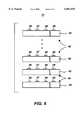
- FIG. 6is a side view of a stack two boards in a multi-dimensional antenna array according to the present invention.
- FIG. 2is a top plan view of a frequency-scanned, end-fire, planar, phased-array antenna 40 according to the present invention.
- the antenna 40generally includes a planar board 42 on which a transmission line 44, a plurality of end-fire antennas 46, 47, 48, 49, a plurality of corresponding couplers 56, 57, 58, 59, and a matched load or termination 61 are formed.
- the number of end-fire antennas 46, 47, 48, 49 and the number of corresponding couplers 56, 57, 58, 59will depend on the designed electromagnetic performance of the specific application.
- planar board 42 used as part of the antenna 40depends on the kind of transmission line used and the end-fire antennas used.
- the board 42is made of a low conductivity microwave dielectric material coated with a highly conductive material.
- the board 42may be made of a conductive material.
- Representative thin planar surfaces for use as part of the board 42are: dielectric substrates, ground planes, etc. While the input to the transmission line segment 63 is depicted as being at edge 65 of the board 42, it should be understood that the input may be located on any edge of the board 42 that is convenient for introducing propagating microwave power into the transmission line 44.
- the board 42is relatively thin but in other embodiments the thickness of the board 42 may vary depending on the applications for which the antenna 40 is designed and the fabrication techniques used.
- the board 42may be a conventional printed circuit (PC) board. While the board 42 is depicted as being flat and rectangularly shaped, it should be understood that other shapes may alternatively be used. For instance, the board 42 may be conformal (i.e., curved or not flat) to a different shape.
- the transmission line 44may be any suitable transmission line, and in particular a planar transmission line or a quasi-planar transmission line.
- the transmission line 44is deposited or formed on the upper surface 64 of the board 42, and follows a sinuous path.
- the transmission line 44is comprised of a plurality of interconnected segments. The locus of the interconnected segments trace a sinuous, back-and-forth, path on the board 42.
- the segments of the transmission line 44are comprised of an input transmission segment 63 that extends from an edge 65 of the board 42 to a coupling segment 67 disposed in proximity to the edge 69 of the board 42. While the input to the transmission segment 63 is depicted as being at edge 65 of the board 42, it should be understood that this input may be located on any edge of the board 42 that is convenient for introducing propagating microwave power into the transmission line 44. Multiple inputs for multiple transmission lines may optionally be used.
- the location of the coupling segment 67 relative to the edge 69may vary with the specific application.
- One function of the coupling segment 67 as well as the other coupling segmentsis to provide sections of the transmission line 44 from which energy can be coupled from the transmission line 44 to the end-fire antennas 46-49.
- the coupling segment 67connects the input transmission segment 63 to a transmission segment 70, which, in turn extends in a return segment 72 located in closer proximity to the edge 65.
- the return segment 72extends in another transmission segment 74 and therefrom in a coupling segment 76, a transmission segment 78, a return segment 79, a transmission segment 81, a coupling segment 83, a transmission segment 85, a return segment 87, a transmission segment 89, a coupling segment 91, a transmission segment 92, and a return segment 94. While only eight transmission segments and eight coupling and return segments are shown, it should be clear to a person of ordinary skill in the field that a different number of transmission segments and corners may alternatively be used.
- the transmission line 44terminates in the matched load or termination 61 in order to absorb any remaining power propagating in the transmission line 44 without reflection back along the sinuous transmission line 44.
- the transmission segmentsare shown to be straight (or linear) and parallel relative to each other. It should be clear that these transmission segments may assume different non linear shapes (i.e., curvilinear) and/or may be non parallel.
- the coupling segmentsare shown to have a similar length and to be parallel and disposed at the same distance from the edge 69 of the board 42. It should be clear that the coupling segments are not necessarily equal in length, nor do they need to be parallel or disposed at a fixed distance from the edge 69. It should also be clear that a similar logic applies to the return segments.
- the coupling and return segmentsare shown to be disposed in a normal (i.e., perpendicular) relationship relative to the transmission segments 63, 70, 74, 78, 81, 85, 89, 92.
- An important, but not an absolute requirementis that the disposition (or angular relationship) among the various segments of the transmission line 44 permit a smooth transition to the propagating wave traveling through the transmission line 44.
- the coupling segments 67, 76, 83, 91are designed to be coupled to acceptable couplers as it will be described later. While only the coupling segments 67, 76, 83, 91 are illustrated as being coupled to the couplers 46-49, it should be clear that in an alternative embodiment the return segments 72, 79, 87, 94 may also be coupled to corresponding couplers. In yet another embodiment, some but not all the coupling and return segments are coupled to corresponding couplers.
- Some representative planar transmission lines that can be used as the transmission line 44are: stripline, microstrip line, inverted microstrip line, slot line, coplanar waveguide, coplanar stripline, etc.
- Some representative dielectric transmission lines that can be used as the transmission line 44are: image line, insulated image line, inverted strip line, trapped image line, etc.
- the transmission line segments comprising transmission line 44need not be all of the same type.
- the transmission line 44is coupled at adequate coupling points or segments (i.e., 67, 76, 83, 91), along its length to integrated end-fire antennas 46-49 located in proximity to the edge 69 of the board 42, for radiating in the end-fire direction (or orientation) indicated by the arrows "R".
- radiation in the end-fire directionmeans radiation substantially parallel to the planar surface of the board 42 and emitted from or along the edge 69 thereof.
- couplers 56-59 shown in FIG. 2are identical. However, in other embodiments the couplers are not necessarily identical and various combinations may be used.
- a coupleris a structure that transfers a certain portion of the power within the transmission line 44 to another structure, which in a preferred embodiment is the end-fire antenna, i.e., 46.
- the construction and design of the couplers 56-59depend on the particular application for which the antenna 40 is used, the particular frequencies used, the particular transmission lines used, the particular end-fine antennas used, etc.
- Representative couplersinclude aperture coupled microstrip lines, DeRonde couplers, broadside coupled microstrip lines, etc.
- the couplers 56-59need not couple the same amount of power from the transmission line 44, nor do they need to couple the same fraction of power from the transmission line 44. Also, all couplers 56-59 need not be of the same design.
- the couplers 56-59may be coupled to any points along the transmission line 44; however, it is desirable that the coupling points be at those locations along the transmission line 44 such that the propagation direction of the resultant end-fire free space radiation field be related to the frequency of the electromagnetic radiation propagating in the transmission line 44.
- a coupleris coupled to each coupling segment. It should be understood that in other embodiments the couplers may be connected to some but not all of the coupling segments 67, 76, 83, 91.
- an end-fire antennais connected to a corresponding coupler.
- an end-fire antennais capable of emitting radiation into free space or an adjacent substance, substantially in the plane or substantially parallel to the plane of the planar surface of the board 42, from, or in proximity to the edge 69 of the board 42.
- Representative integrated end-fire antennasare: tapered dielectric rod, Vivaldi antenna, slot antenna, dipole antenna, etc.
- the transmission line 44is shown to be comprised of: transmission line segments 63, 70, 74, 78, 81, 85, 89, 92; coupling segments 67, 76, 83, 91; return segments 72, 79, 87, 94; matched load 61; couplers 56, 57, 58, 59; bends; input.
- one or more additional transmission line elementsmay be used, depending on the particular design of the antenna 40, such as: impedance transformers, filters, power dividers, adapters, etc.
- the end-fire antennas 46-49are directed in the same orientation. However, in another embodiment the end-fire antennas 46-49 may have different orientations. In a preferred embodiment the end-fire antennas along the edge 69 are adjacent to each other. In order for the end-fire antennas 46-49 to perform efficiently for a particular application the end-fire antennas 46-49 are not spaced farther apart than about one half (1/2) the free-space wavelength of the radiation emitted by the end-fire antennas 46-49; otherwise, the radiation pattern of the antenna 40 may contain grating lobes.
- the antenna 40uses a single dimensional array, i.e., a single board 42.
- a single dimensional arrayproduces a fan beam
- a multi-dimensional arrayproduces a pencil beam.
- the various stacked antennas 40are connected together and radiate at the same frequency.
- each antenna 40 in the stackradiates at a different frequency. For instance, and without intent to limit the scope of the invention, one antenna radiates at a frequency "f1", while the remaining antennas radiate at other desirable frequencies "f2", "f3", etc.
- end-fire antennas 46-49 of a two-dimensional arrayare located along the same side (i.e., edge 69) of the boards 42.
- the end-fire antennasmay additionally or alternatively be located along one or more other sides (i.e., edge 65).
- the concept of the present inventionmay equally be used to radiate at other than microwave and millimeter-wave frequencies.
- the present inventioncan be used in the terahertz, infrared, and optical frequency ranges by utilizing components, such as transmission lines, couplers, end-fire antennas, matched terminations, amplifiers, etc., designed for those particular frequencies.
- single-mode optical fiberscan be used for transmission lines in the infrared frequency range.
- the antenna 40is located on a spinning or rotatable platform.
- the couplers 56-59 and the coupling segments 67, 76, 83, 91are disposed in substantial alignment with their corresponding end-fire antennas 46-49.
- the end-fire antennas 46-49since it would be desirable to position the end-fire antennas 46-49 as close as possible, consistent with the dimension and electromagnetic properties of the end-fire antennas 46-49, but not farther apart than about one half (1/2) the free-space wavelength of the radiation emitted by the end-fire antennas 46-49, such a limitation would generally equally apply to the coupling segments 67, 76, 83, 91 as well.
- the coupling segments 67, 76, 83, 91 and the return segments 72, 79, 87, 94may form relatively sharp turns with respect to the transmission segments 63, 70, 74, 78, 81, 85, 89, 92, thus causing undesirable radiation from the sharp turns and consequent contamination of the radiation emitted by the end-fire antennas 46-49.
- undesirable radiation from sharp turnsreduces the power available in the transmission line 44.
- FIG. 5illustrates an alternative embodiment of an antenna 100 according to the present invention, with similar components to those of the antenna 40 being similarly referenced.
- the antenna 100provides a solution to reduce the necessity for sharp turns within the transmission line 102.
- the end-fire antennas 46-49are still preferably not farther apart than about one half (1/2) the free-space wavelength of the radiation emitted by the end-fire antennas 46-49, but the coupling segments 107, 108, 109, 110, as well as the couplers 56-59 are located as far apart as needed to accomplish smooth tums, and hence efficient transmission of the power through the transmission line 102.
- Each connecting transmission linefor instance 115, connects a coupler, for instance 56, to its corresponding end-fire antenna, for instance 46. It is also possible to have two or more connecting lines connected to a single coupler for connecting this coupler to two or more end-fire antennas that may be located either on the same edge (i.e., 69), or on other edges (i.e., 65) of the board 42.
- the coupler 57is shown coupled to two connecting transmission lines: a first connecting transmission line 116 connected to the end-fire antenna 46 in proximity to the edge 69, and a second connecting transmission line 120 is connected to another end-fire antenna 122 positioned in proximity to the edge 65.
- all the connecting transmission lines to the end-fire antennasare equal in length. However, in other designs the connecting transmission lines may have different lengths.
- an amplifieris positioned along a connecting transmission line, between a coupler and its corresponding end-fire antenna.
- the antenna 100 illustrated in FIG. 5is shown equipped with four amplifiers 125, 126, 127, 128.
- the gain and phase characteristics of these amplifiers 125-128may be the same, different or programmable by means of a control chip (not shown).
- an amplifieris positioned along a transmission segment of the transmission line 102.
- amplifiers 130, 132, 133, 134, 135, 136are shown connected to the various transmission segments of the transmission line 102.
- the gain and phase characteristics of these amplifiers 130-135may be the same, different or programmable by means of a control chip (not shown).
- the antennas 40 and 100 of FIGS. 2 and 5, respectively,are described as being formed on one side, i.e, the top side of the board 42. It should be understood that duplicate or similar antennas may additionally be formed on the bottom side of the board 42.
- FIGS. 3 and 4illustrate an alternative antenna 200 wherein the sinuous transmission line 202 is formed on the upper surface 64 of the board 42, while the connecting transmission lines 115-118 and the end-fire antennas 46-49 are disposed on the bottom surface 205 of the board 42.
- the couplers 56-59extend through the board surfaces 64 and 205 to complete the energy coupling exchange. While the antenna 200 is shown to be a variation of the antenna 100 of FIG. 5, it should be understood that the same or an equivalent concept may be extended to the antenna 40 as well as to other embodiments described herein.
Landscapes
- Variable-Direction Aerials And Aerial Arrays (AREA)
Abstract
Description
The invention described herein may be manufactured and used by or for the Government of the United States for governmental purposes.
This application claims benefit of the filing date of provisional application Ser. No. 60/040,904 filed on Apr. 2, 1997.
The present invention relates in general to antennas, and it more specifically relates to a sinuous, frequency-scanned, end-fire, planar phased-array antenna.
Frequency-scanned phased-array antennas are well known in the field and are usually operated at bandwidths that are at least a few percent. The traditional frequency-scanned phased array antenna using "hollow pipe" electromagnetic waveguide is described in detail in the book titled "Microwave Scanning Antennas", by R. C. Hansen, Vol.3, chapter two, Academic press, 1966. Although this technology has been very successful, it has limited present day applications because "hollow pipe" waveguide elements are too voluminous for the solid state, printed circuitry requirements now in widespread use for microwave and millimeter-wave radars. In addition, the bandwidths required (usually grater than six percent) are too large for practical solid-state millimeter-wave radars, which significantly limits the commercial applications of this technology.
FIG. 1 illustrates a more recent prior art frequency-scanned phased-array antenna 10 shown usingelectromagnetic transmission line 12 such as a microstrip. The operation of the frequency-scanned phased-array antenna 10 is described in greater detail in the article titled "Frequency Scanning Microstrip Antennas", by Magnus Danielsen and Roff Jorgensen, in IEEE Transactions on Antennas and Propagation, Vol. AP-27, No. 2, March 1979, pages 146-150, which article is incorporated herein by reference.
The Danielsen et al. article proposes a frequency-scanned phased-array antenna design where thetransmission line 12 is formed of a plurality of segments, i.e., 14, 15, 16 that meander back and forth between successive patch radiating resonators, i.e., 18, 19, 20, 21. This meandering increases the electrical length of the transmission line segments between successive patch resonators. Therefore, the phase shift imparted by thetransmission line 12 to a traveling wave is likewise substantially increased. In addition it should be noted that each patch resonator itself imparts a significant phase shift to the traveling wave.
However, the physical length and the electrical length of each microstriptransmission line segment patch resonators
An object of the present invention is to provide a frequency-scanned phased-array antenna that can achieve a +45 degree to -45 degree scan range using a sinuous planar transmission line with a frequency bandwidth of one percent or less.
It is another object of the present invention to obtain the largest variation in the electrical length of the sinuous transmission line for the smallest variation in frequency. The antenna of the present invention further provides a rugged frequency scanned phased array.
The present antenna significantly reduces the size and cost of phased-array antennas, and expands their potential use in numerous commercial applications. For instance the present antenna may be used in a variety of applications including but not limited to missiles, smart munitions, anti-collision devices for vehicles, sensors, general aviation, communications systems, etc.
According to this invention, the frequency-scanned end-fire phased-array antenna includes a board, a sinuous transmission line formed on the board, a plurality of end-fire antennas, and a plurality of couplers corresponding to the end-fire antennas, such that the transmission line is selectively coupled to the plurality of end-fire antennas via the plurality of couplers, for selectively coupling energy within the transmission line to the end-fire antennas.
By varying the input frequency to the antenna over a narrow range, the direction of a main radiation beam emitted by the antenna can be scanned ±90 degrees from broadside. A single antenna board produces a frequency-scanned fan beam. Stacked antenna boards can produce a frequency-scanned pencil beam, or several independent frequency-scanned fan beams at different frequencies. The present antenna can operate in the microwave, millimeter-wave, terahertz, infrared, or optical frequency range. Because this frequency-scanned phased-array can be mass produced by planar fabrication techniques, it can be much smaller and less expensive than conventional hollow pipe waveguide frequency-scanned phased-array antennas.
The above and other features of the present invention and the manner of attaining them, will become apparent, and the invention itself will be best understood, by reference to the following description and the accompanying drawings, wherein:
FIG. 1 is a schematic view of a prior art frequency scanned microstrip patch array antenna;
FIG. 2 is a schematic view of a sinuous, frequency-scanned, end-fire, planar, phased-array antenna according to the present invention;
FIG. 3 is a schematic top plan view of an alternative embodiment of a sinuous, frequency-scanned, end-fire, planar, phased-array antenna according to the present invention;
FIG. 4 is the bottom view of the frequency-scanned, end-fire, planar, phased-array antenna of FIG. 3;
FIG. 5 is a schematic top plan view of another frequency-scanned, end-fire, planar, phased-array antenna according to the present invention; and
FIG. 6 is a side view of a stack two boards in a multi-dimensional antenna array according to the present invention.
Similar numerals refer to similar elements in the drawing. It should be understood that the sizes of the different components in the figures may not be in exact proportion, and are shown for visual clarity and for the purpose of explanation.
FIG. 2 is a top plan view of a frequency-scanned, end-fire, planar, phased-array antenna 40 according to the present invention. Theantenna 40 generally includes aplanar board 42 on which atransmission line 44, a plurality of end-fire antennas corresponding couplers termination 61 are formed. The number of end-fire antennas corresponding couplers
The type ofplanar board 42 used as part of theantenna 40 depends on the kind of transmission line used and the end-fire antennas used. In a preferred embodiment theboard 42 is made of a low conductivity microwave dielectric material coated with a highly conductive material. However, in alternative embodiments theboard 42 may be made of a conductive material. Representative thin planar surfaces for use as part of theboard 42 are: dielectric substrates, ground planes, etc. While the input to thetransmission line segment 63 is depicted as being atedge 65 of theboard 42, it should be understood that the input may be located on any edge of theboard 42 that is convenient for introducing propagating microwave power into thetransmission line 44.
In this particular example theboard 42 is relatively thin but in other embodiments the thickness of theboard 42 may vary depending on the applications for which theantenna 40 is designed and the fabrication techniques used. In a specific exemplary embodiment theboard 42 may be a conventional printed circuit (PC) board. While theboard 42 is depicted as being flat and rectangularly shaped, it should be understood that other shapes may alternatively be used. For instance, theboard 42 may be conformal (i.e., curved or not flat) to a different shape.
Thetransmission line 44 may be any suitable transmission line, and in particular a planar transmission line or a quasi-planar transmission line. In a preferred embodiment thetransmission line 44 is deposited or formed on theupper surface 64 of theboard 42, and follows a sinuous path. Thetransmission line 44 is comprised of a plurality of interconnected segments. The locus of the interconnected segments trace a sinuous, back-and-forth, path on theboard 42.
The segments of thetransmission line 44 are comprised of aninput transmission segment 63 that extends from anedge 65 of theboard 42 to acoupling segment 67 disposed in proximity to theedge 69 of theboard 42. While the input to thetransmission segment 63 is depicted as being atedge 65 of theboard 42, it should be understood that this input may be located on any edge of theboard 42 that is convenient for introducing propagating microwave power into thetransmission line 44. Multiple inputs for multiple transmission lines may optionally be used. The location of thecoupling segment 67 relative to theedge 69 may vary with the specific application. One function of thecoupling segment 67 as well as the other coupling segments is to provide sections of thetransmission line 44 from which energy can be coupled from thetransmission line 44 to the end-fire antennas 46-49.
Thecoupling segment 67 connects theinput transmission segment 63 to atransmission segment 70, which, in turn extends in areturn segment 72 located in closer proximity to theedge 65. Similarly, but not necessarily identically, thereturn segment 72 extends in anothertransmission segment 74 and therefrom in acoupling segment 76, atransmission segment 78, areturn segment 79, atransmission segment 81, acoupling segment 83, atransmission segment 85, areturn segment 87, atransmission segment 89, acoupling segment 91, atransmission segment 92, and areturn segment 94. While only eight transmission segments and eight coupling and return segments are shown, it should be clear to a person of ordinary skill in the field that a different number of transmission segments and corners may alternatively be used. Thetransmission line 44 terminates in the matched load ortermination 61 in order to absorb any remaining power propagating in thetransmission line 44 without reflection back along thesinuous transmission line 44.
In this particular example, and for ease of illustration, the transmission segments are shown to be straight (or linear) and parallel relative to each other. It should be clear that these transmission segments may assume different non linear shapes (i.e., curvilinear) and/or may be non parallel. In addition, the coupling segments are shown to have a similar length and to be parallel and disposed at the same distance from theedge 69 of theboard 42. It should be clear that the coupling segments are not necessarily equal in length, nor do they need to be parallel or disposed at a fixed distance from theedge 69. It should also be clear that a similar logic applies to the return segments.
In the specific example shown in FIG. 2 the coupling and return segments are shown to be disposed in a normal (i.e., perpendicular) relationship relative to thetransmission segments transmission line 44. An important, but not an absolute requirement is that the disposition (or angular relationship) among the various segments of thetransmission line 44 permit a smooth transition to the propagating wave traveling through thetransmission line 44.
An additional desirable criterion for thetransmission line 44 is that thecoupling segments coupling segments return segments
Some representative planar transmission lines that can be used as thetransmission line 44 are: stripline, microstrip line, inverted microstrip line, slot line, coplanar waveguide, coplanar stripline, etc. Some representative dielectric transmission lines that can be used as thetransmission line 44 are: image line, insulated image line, inverted strip line, trapped image line, etc. The transmission line segments comprisingtransmission line 44 need not be all of the same type.
As mentioned previously, thetransmission line 44 is coupled at adequate coupling points or segments (i.e., 67, 76, 83, 91), along its length to integrated end-fire antennas 46-49 located in proximity to theedge 69 of theboard 42, for radiating in the end-fire direction (or orientation) indicated by the arrows "R". As used herein radiation in the end-fire direction means radiation substantially parallel to the planar surface of theboard 42 and emitted from or along theedge 69 thereof.
The couplers 56-59 shown in FIG. 2 are identical. However, in other embodiments the couplers are not necessarily identical and various combinations may be used. As used herein, a coupler is a structure that transfers a certain portion of the power within thetransmission line 44 to another structure, which in a preferred embodiment is the end-fire antenna, i.e., 46.
The construction and design of the couplers 56-59 depend on the particular application for which theantenna 40 is used, the particular frequencies used, the particular transmission lines used, the particular end-fine antennas used, etc. Representative couplers include aperture coupled microstrip lines, DeRonde couplers, broadside coupled microstrip lines, etc. The couplers 56-59 need not couple the same amount of power from thetransmission line 44, nor do they need to couple the same fraction of power from thetransmission line 44. Also, all couplers 56-59 need not be of the same design.
The couplers 56-59 may be coupled to any points along thetransmission line 44; however, it is desirable that the coupling points be at those locations along thetransmission line 44 such that the propagation direction of the resultant end-fire free space radiation field be related to the frequency of the electromagnetic radiation propagating in thetransmission line 44.
In the embodiment shown in FIG. 2 a coupler is coupled to each coupling segment. It should be understood that in other embodiments the couplers may be connected to some but not all of thecoupling segments
Considering now the end-fire antennas 46-49, one end-fire antenna is connected to a corresponding coupler. As used herein, an end-fire antenna is capable of emitting radiation into free space or an adjacent substance, substantially in the plane or substantially parallel to the plane of the planar surface of theboard 42, from, or in proximity to theedge 69 of theboard 42. Representative integrated end-fire antennas are: tapered dielectric rod, Vivaldi antenna, slot antenna, dipole antenna, etc.
In the specific example shown in FIG. 2 thetransmission line 44 is shown to be comprised of:transmission line segments coupling segments segments load 61;couplers antenna 40, such as: impedance transformers, filters, power dividers, adapters, etc.
The end-fire antennas 46-49 are directed in the same orientation. However, in another embodiment the end-fire antennas 46-49 may have different orientations. In a preferred embodiment the end-fire antennas along theedge 69 are adjacent to each other. In order for the end-fire antennas 46-49 to perform efficiently for a particular application the end-fire antennas 46-49 are not spaced farther apart than about one half (1/2) the free-space wavelength of the radiation emitted by the end-fire antennas 46-49; otherwise, the radiation pattern of theantenna 40 may contain grating lobes.
In the present embodiment theantenna 40 uses a single dimensional array, i.e., asingle board 42. However, as illustrated in FIG. 6, it is possible to stack two ormore boards 42 for obtaining a multi-dimensional (i.e., two-dimensional)antenna array 71. According to one embodiment of the present invention a single dimensional array produces a fan beam, while a multi-dimensional array produces a pencil beam.
In one embodiment according to the present invention the variousstacked antennas 40 are connected together and radiate at the same frequency. In another embodiment eachantenna 40 in the stack radiates at a different frequency. For instance, and without intent to limit the scope of the invention, one antenna radiates at a frequency "f1", while the remaining antennas radiate at other desirable frequencies "f2", "f3", etc.
In one embodiment the end-fire antennas 46-49 of a two-dimensional array are located along the same side (i.e., edge 69) of theboards 42. However, in alternative embodiments the end-fire antennas may additionally or alternatively be located along one or more other sides (i.e., edge 65).
The concept of the present invention may equally be used to radiate at other than microwave and millimeter-wave frequencies. For instance, the present invention can be used in the terahertz, infrared, and optical frequency ranges by utilizing components, such as transmission lines, couplers, end-fire antennas, matched terminations, amplifiers, etc., designed for those particular frequencies. In one particular embodiment single-mode optical fibers can be used for transmission lines in the infrared frequency range. In another embodiment theantenna 40 is located on a spinning or rotatable platform.
In one exemplary embodiment of theantenna 40 of FIG. 2 the couplers 56-59 and thecoupling segments coupling segments coupling segments return segments transmission segments transmission line 44.
FIG. 5 illustrates an alternative embodiment of anantenna 100 according to the present invention, with similar components to those of theantenna 40 being similarly referenced. Theantenna 100 provides a solution to reduce the necessity for sharp turns within thetransmission line 102. In theantenna 100 the end-fire antennas 46-49 are still preferably not farther apart than about one half (1/2) the free-space wavelength of the radiation emitted by the end-fire antennas 46-49, but thecoupling segments transmission line 102.
This objective is achieved by adding a plurality of connectingtransmission lines instance 115, connects a coupler, forinstance 56, to its corresponding end-fire antenna, forinstance 46. It is also possible to have two or more connecting lines connected to a single coupler for connecting this coupler to two or more end-fire antennas that may be located either on the same edge (i.e., 69), or on other edges (i.e., 65) of theboard 42. For illustration purpose only, thecoupler 57 is shown coupled to two connecting transmission lines: a first connectingtransmission line 116 connected to the end-fire antenna 46 in proximity to theedge 69, and a second connectingtransmission line 120 is connected to another end-fire antenna 122 positioned in proximity to theedge 65. In one embodiment all the connecting transmission lines to the end-fire antennas are equal in length. However, in other designs the connecting transmission lines may have different lengths.
In a preferred embodiment an amplifier is positioned along a connecting transmission line, between a coupler and its corresponding end-fire antenna. Theantenna 100 illustrated in FIG. 5 is shown equipped with fouramplifiers
In another preferred embodiment an amplifier is positioned along a transmission segment of thetransmission line 102. For instance,amplifiers transmission line 102. The gain and phase characteristics of these amplifiers 130-135 may be the same, different or programmable by means of a control chip (not shown).
Theantennas board 42. It should be understood that duplicate or similar antennas may additionally be formed on the bottom side of theboard 42.
FIGS. 3 and 4 illustrate analternative antenna 200 wherein thesinuous transmission line 202 is formed on theupper surface 64 of theboard 42, while the connecting transmission lines 115-118 and the end-fire antennas 46-49 are disposed on thebottom surface 205 of theboard 42. The couplers 56-59 extend through the board surfaces 64 and 205 to complete the energy coupling exchange. While theantenna 200 is shown to be a variation of theantenna 100 of FIG. 5, it should be understood that the same or an equivalent concept may be extended to theantenna 40 as well as to other embodiments described herein.
It should be apparent that many modifications may be made to the invention without departing from the spirit and scope of the invention. Therefore, the drawings, and description relating to the use of the invention are presented only for the purposes of illustration and direction. For instance, the present invention may be extended to non-planar phased-array antennas. In addition, while the transmission line has been described as being sinuous, it should clear that linear or non-sinuous transmission lines may be used instead. It is also clear that the condition that the end-fire antennas be not farther apart than about one half (1/2) the free space wavelength of the radiation emitted by the end-fire antennas can be also achieved by using an interlaced array as described in the book titled "Microwave Scanning Antennas", by R. C. Hansen, Vol. 3, Chapter two, Academic Press, 1966.
Claims (40)
1. A frequency-scanned, phased-array antenna comprising in combination:
a board having an edge;
a transmission line formed on said board, and having an input;
a plurality of end-fire antennas secured to said board;
a plurality of couplers secured to said board and corresponding to said end-fire antennas;
said transmission line being selectively coupled to said plurality of end-fire antennas via said plurality of couplers, for selectively coupling energy within said transmission line to said end-fire antennas; and
wherein said transmission line includes a single, sinuous transmission line in order to enable frequency scanning.
2. The antenna according to claim 1, further including a matched load or termination.
3. The antenna according to claim 1, wherein said input of said transmission line is located at said board edge.
4. The antenna according to claim 1, wherein said board is planar.
5. The antenna according to claim 1, wherein said board is conformal to a non-planar shape.
6. The antenna according to claim 1, wherein said transmission line is planar.
7. The antenna according to claim 1, wherein said transmission line is substantially planar.
8. The antenna according to claim 1, wherein said transmission line includes a plurality of interconnected segments.
9. The antenna according to claim 8, wherein said interconnected segments include a plurality of transmission segments that are connected by a plurality of coupling segments.
10. The antenna according to claim 9, wherein said plurality of couplers are coupled to said plurality of coupling segments.
11. The antenna according to claim 10, wherein said transmission segments include an input transmission segment that extends from said board edge to one of said coupling segments.
12. The antenna according to claim 11, wherein at least some of said transmission segments are linearly shaped.
13. The antenna according to claim 11, wherein at least some of said transmission segments are curvilinearly shaped.
14. The antenna according to claim 8, wherein at least some of said plurality of interconnected segments are of the same type.
15. The antenna according to claim 1, wherein said transmission line is any of: a stripline, a microstrip, an inverted microstrip line, a slotline, a coplanar waveguide, an image line, an insulated image line, a tapped image line, a coplanar stripline.
16. The antenna according to claim 1, wherein each of said end-fire antennas is any of: a tapered dielectric rod, a Vivaldi type antenna, a slot antenna, a dipole antenna.
17. The antenna according to claim 1, wherein said end-fire antennas radiate energy having a predetermined frequency and wavelength;
wherein said end-fire antennas are not farther apart than about one half (1/2) said wavelength of radiation emitted by said end-fire antennas; and
wherein said couplers are located as far apart as needed to accomplish smooth turns of said transmission line.
18. The antenna according to claim 1, further including a plurality of connecting transmission lines; and
wherein each connecting transmission line connects a coupler to a corresponding end-fire antenna.
19. The antenna according to claim 18, wherein said board has a first side and second side;
wherein said transmission line is formed on said first side; and
said connecting transmission lines are disposed on said second side.
20. The antenna according to claim 1, further including an amplifier positioned along a connecting transmission line, between a coupler and a corresponding end-fire antenna.
21. The antenna according to claim 1, further including an amplifier positioned along a transmission segment of said transmission line.
22. The antenna according to claim 1, wherein said transmission line is single-mode optical fiber.
23. The antenna according to claim 1, wherein at least some of said plurality of end-fire antennas are formed on said board.
24. The antenna according to claim 1, wherein at least some of said plurality of couplers are formed on said board and coupled to corresponding end-fire antennas.
25. The antenna according to claim 1, wherein at least some of said end-fire antennas radiate from said edge, in a direction substantially parallel to a surface of said board.
26. A frequency-scanned, multi-dimensional phased-array antenna comprising in combination:
two or more boards in a stacked relationship, each board having an edge;
a transmission line formed on each of said board; and having an input;
a plurality of end-fire antennas secured to each of said boards;
a plurality of couplers secured to each of said board and corresponding to said end-fire antennas;
said transmission line being selectively coupled to said plurality of end-fire antennas via said plurality of couplers, for selectively coupling energy within said transmission line to said end-fire antennas; and
wherein said transmission line includes a single, sinuous transmission line in order to enable frequency scanning.
27. The antenna according to claim 26, wherein the antenna produces a fan beam.
28. The antenna according to claim 26, wherein the antenna produces a pencil beam.
29. The antenna according to claim 26, wherein said boards and corresponding ones of said transmission line, end-fire antennas, and couplers formed on each of said board form separate frequency-scanned antennas; and
wherein said frequency-scanned antennas are selectively grouped pursuant to frequency ranges.
30. The antenna according to claim 26, wherein said frequency-scanned antennas radiate at the same frequency.
31. The antenna according to claim 26, wherein said frequency-scanned antennas radiate at different frequencies.
32. The antenna according to claim 26, wherein at least some of said frequency-scanned antennas radiate at a first frequency, and at least some of said frequency-scanned antennas radiate another desirable frequencies.
33. The antenna according to claim 26, wherein at least some of said plurality of end-fire antennas are formed on said board.
34. The antenna according to claim 26, wherein at least some of said plurality of couplers are formed on said board and coupled to corresponding end-fire antennas.
35. A method of making a frequency-scanned, phased-array antenna comprising:
forming a transmission line with an input on a board;
forming a plurality of energy radiating elements in proximity to an edge of said board;
forming a plurality of couplers corresponding to said energy radiating elements on said board;
selectively securing said transmission line to said plurality of energy radiating elements via said plurality of couplers, for selectively coupling energy within said transmission line to energy radiating elements; and
wherein forming said transmission line includes forming a single, sinuous transmission line in order to enable frequency scanning.
36. The method according to claim 35, further including stacking two or more boards including said transmission line, plurality of energy radiating elements, and couplers, on top of each other.
37. The method according to claim 35, wherein at least one of the steps of: forming said transmission line, forming said energy radiating elements, and forming said plurality of couplers includes etching said board.
38. The method according to claim 37, wherein the steps of: forming said transmission line, forming said energy radiating elements, and forming said plurality of couplers include etching said board.
39. A frequency-scanned, phased-array antenna comprising:
a first board having an edge;
a first planar-type transmission line formed on said board, and having an input;
a plurality of energy radiating elements formed on said board;
a plurality of couplers formed on said board; and
said first transmission line being selectively coupled to said plurality of energy radiating elements via said plurality of couplers, for selectively coupling energy within said first transmission line to said energy radiating elements, and
wherein said first transmission line includes a single, sinuous transmission line in order to enable frequency scanning.
40. The antenna according to claim 39, further including a second board with a second transmission line, a plurality of energy radiating elements, and a plurality of couplers formed on said second board; and
wherein said first board and second board are secured to each other.
Priority Applications (1)
| Application Number | Priority Date | Filing Date | Title |
|---|---|---|---|
| US09/053,860US6061035A (en) | 1997-04-02 | 1998-03-22 | Frequency-scanned end-fire phased-aray antenna |
Applications Claiming Priority (2)
| Application Number | Priority Date | Filing Date | Title |
|---|---|---|---|
| US4090497P | 1997-04-02 | 1997-04-02 | |
| US09/053,860US6061035A (en) | 1997-04-02 | 1998-03-22 | Frequency-scanned end-fire phased-aray antenna |
Publications (1)
| Publication Number | Publication Date |
|---|---|
| US6061035Atrue US6061035A (en) | 2000-05-09 |
Family
ID=26717581
Family Applications (1)
| Application Number | Title | Priority Date | Filing Date |
|---|---|---|---|
| US09/053,860Expired - Fee RelatedUS6061035A (en) | 1997-04-02 | 1998-03-22 | Frequency-scanned end-fire phased-aray antenna |
Country Status (1)
| Country | Link |
|---|---|
| US (1) | US6061035A (en) |
Cited By (181)
| Publication number | Priority date | Publication date | Assignee | Title |
|---|---|---|---|---|
| US6323814B1 (en)* | 2000-05-24 | 2001-11-27 | Bae Systems Information And Electronic Systems Integration Inc | Wideband meander line loaded antenna |
| US6404391B1 (en)* | 2001-01-25 | 2002-06-11 | Bae Systems Information And Electronic System Integration Inc | Meander line loaded tunable patch antenna |
| US6424319B2 (en) | 1999-11-18 | 2002-07-23 | Automotive Systems Laboratory, Inc. | Multi-beam antenna |
| US6538614B2 (en) | 2001-04-17 | 2003-03-25 | Lucent Technologies Inc. | Broadband antenna structure |
| US6606077B2 (en) | 1999-11-18 | 2003-08-12 | Automotive Systems Laboratory, Inc. | Multi-beam antenna |
| WO2004008575A1 (en)* | 2002-07-11 | 2004-01-22 | Commonwealth Scientific And Industrial Research Organisation | Real-time, cross-correlating millimetre-wave imaging system |
| US6690331B2 (en) | 2000-05-24 | 2004-02-10 | Bae Systems Information And Electronic Systems Integration Inc | Beamforming quad meanderline loaded antenna |
| US20050068251A1 (en)* | 1999-11-18 | 2005-03-31 | Automotive Systems Laboratory, Inc. | Multi-beam antenna |
| US20050219126A1 (en)* | 2004-03-26 | 2005-10-06 | Automotive Systems Laboratory, Inc. | Multi-beam antenna |
| US20060028386A1 (en)* | 1999-11-18 | 2006-02-09 | Ebling James P | Multi-beam antenna |
| US20060273972A1 (en)* | 2005-06-02 | 2006-12-07 | Chandler Cole A | Millimeter wave electronically scanned antenna |
| US20060273973A1 (en)* | 2005-06-02 | 2006-12-07 | Chandler Cole A | Millimeter wave passive electronically scanned antenna |
| US20070195004A1 (en)* | 1999-11-18 | 2007-08-23 | Gabriel Rebeiz | Multi-beam antenna |
| US20080024305A1 (en)* | 2006-07-28 | 2008-01-31 | Deavours Daniel D | Planar microstrip antenna integrated into container |
| US20080284651A1 (en)* | 2005-11-21 | 2008-11-20 | Plextek Limited | Radar system |
| US20100013708A1 (en)* | 2006-12-27 | 2010-01-21 | Lockheed Martin Corporation | Directive spatial interference beam control |
| CN101888019A (en)* | 2009-05-13 | 2010-11-17 | 南京理工大学 | Frequency Scanning Antenna Array with Wide Angle Scanning in Limited Bandwidth |
| US20130120204A1 (en)* | 2010-03-26 | 2013-05-16 | Thomas Schoeberl | Microwave scanner |
| CN103956575A (en)* | 2014-04-28 | 2014-07-30 | 零八一电子集团有限公司 | Large X-band broadband frequency phase scanning antenna array |
| WO2016202394A1 (en)* | 2015-06-18 | 2016-12-22 | Vega Grieshaber Kg | Waveguide coupling for a line scanner |
| US9608740B2 (en) | 2015-07-15 | 2017-03-28 | At&T Intellectual Property I, L.P. | Method and apparatus for launching a wave mode that mitigates interference |
| US9615269B2 (en) | 2014-10-02 | 2017-04-04 | At&T Intellectual Property I, L.P. | Method and apparatus that provides fault tolerance in a communication network |
| US9628116B2 (en) | 2015-07-14 | 2017-04-18 | At&T Intellectual Property I, L.P. | Apparatus and methods for transmitting wireless signals |
| US9640850B2 (en) | 2015-06-25 | 2017-05-02 | At&T Intellectual Property I, L.P. | Methods and apparatus for inducing a non-fundamental wave mode on a transmission medium |
| CN106656246A (en)* | 2016-10-31 | 2017-05-10 | 努比亚技术有限公司 | Signal transmission system based on serpentine wire and mobile terminal |
| US9667317B2 (en) | 2015-06-15 | 2017-05-30 | At&T Intellectual Property I, L.P. | Method and apparatus for providing security using network traffic adjustments |
| US9674711B2 (en) | 2013-11-06 | 2017-06-06 | At&T Intellectual Property I, L.P. | Surface-wave communications and methods thereof |
| US9685992B2 (en) | 2014-10-03 | 2017-06-20 | At&T Intellectual Property I, L.P. | Circuit panel network and methods thereof |
| US9692101B2 (en) | 2014-08-26 | 2017-06-27 | At&T Intellectual Property I, L.P. | Guided wave couplers for coupling electromagnetic waves between a waveguide surface and a surface of a wire |
| US9699785B2 (en) | 2012-12-05 | 2017-07-04 | At&T Intellectual Property I, L.P. | Backhaul link for distributed antenna system |
| US9705610B2 (en) | 2014-10-21 | 2017-07-11 | At&T Intellectual Property I, L.P. | Transmission device with impairment compensation and methods for use therewith |
| US9705561B2 (en) | 2015-04-24 | 2017-07-11 | At&T Intellectual Property I, L.P. | Directional coupling device and methods for use therewith |
| US9722318B2 (en) | 2015-07-14 | 2017-08-01 | At&T Intellectual Property I, L.P. | Method and apparatus for coupling an antenna to a device |
| US9729197B2 (en) | 2015-10-01 | 2017-08-08 | At&T Intellectual Property I, L.P. | Method and apparatus for communicating network management traffic over a network |
| US9735833B2 (en) | 2015-07-31 | 2017-08-15 | At&T Intellectual Property I, L.P. | Method and apparatus for communications management in a neighborhood network |
| US9742462B2 (en) | 2014-12-04 | 2017-08-22 | At&T Intellectual Property I, L.P. | Transmission medium and communication interfaces and methods for use therewith |
| US9742521B2 (en) | 2014-11-20 | 2017-08-22 | At&T Intellectual Property I, L.P. | Transmission device with mode division multiplexing and methods for use therewith |
| US9749013B2 (en) | 2015-03-17 | 2017-08-29 | At&T Intellectual Property I, L.P. | Method and apparatus for reducing attenuation of electromagnetic waves guided by a transmission medium |
| US9749053B2 (en) | 2015-07-23 | 2017-08-29 | At&T Intellectual Property I, L.P. | Node device, repeater and methods for use therewith |
| US9748626B2 (en) | 2015-05-14 | 2017-08-29 | At&T Intellectual Property I, L.P. | Plurality of cables having different cross-sectional shapes which are bundled together to form a transmission medium |
| US9762289B2 (en) | 2014-10-14 | 2017-09-12 | At&T Intellectual Property I, L.P. | Method and apparatus for transmitting or receiving signals in a transportation system |
| US9768833B2 (en) | 2014-09-15 | 2017-09-19 | At&T Intellectual Property I, L.P. | Method and apparatus for sensing a condition in a transmission medium of electromagnetic waves |
| US9769128B2 (en) | 2015-09-28 | 2017-09-19 | At&T Intellectual Property I, L.P. | Method and apparatus for encryption of communications over a network |
| US9769020B2 (en) | 2014-10-21 | 2017-09-19 | At&T Intellectual Property I, L.P. | Method and apparatus for responding to events affecting communications in a communication network |
| US9780834B2 (en) | 2014-10-21 | 2017-10-03 | At&T Intellectual Property I, L.P. | Method and apparatus for transmitting electromagnetic waves |
| US9787412B2 (en) | 2015-06-25 | 2017-10-10 | At&T Intellectual Property I, L.P. | Methods and apparatus for inducing a fundamental wave mode on a transmission medium |
| US9793954B2 (en) | 2015-04-28 | 2017-10-17 | At&T Intellectual Property I, L.P. | Magnetic coupling device and methods for use therewith |
| US9793955B2 (en) | 2015-04-24 | 2017-10-17 | At&T Intellectual Property I, Lp | Passive electrical coupling device and methods for use therewith |
| US9793951B2 (en) | 2015-07-15 | 2017-10-17 | At&T Intellectual Property I, L.P. | Method and apparatus for launching a wave mode that mitigates interference |
| US9800327B2 (en) | 2014-11-20 | 2017-10-24 | At&T Intellectual Property I, L.P. | Apparatus for controlling operations of a communication device and methods thereof |
| US9820146B2 (en) | 2015-06-12 | 2017-11-14 | At&T Intellectual Property I, L.P. | Method and apparatus for authentication and identity management of communicating devices |
| US9838078B2 (en) | 2015-07-31 | 2017-12-05 | At&T Intellectual Property I, L.P. | Method and apparatus for exchanging communication signals |
| US9838896B1 (en) | 2016-12-09 | 2017-12-05 | At&T Intellectual Property I, L.P. | Method and apparatus for assessing network coverage |
| US9847566B2 (en) | 2015-07-14 | 2017-12-19 | At&T Intellectual Property I, L.P. | Method and apparatus for adjusting a field of a signal to mitigate interference |
| US9847850B2 (en) | 2014-10-14 | 2017-12-19 | At&T Intellectual Property I, L.P. | Method and apparatus for adjusting a mode of communication in a communication network |
| US9853342B2 (en) | 2015-07-14 | 2017-12-26 | At&T Intellectual Property I, L.P. | Dielectric transmission medium connector and methods for use therewith |
| US9860075B1 (en) | 2016-08-26 | 2018-01-02 | At&T Intellectual Property I, L.P. | Method and communication node for broadband distribution |
| US9865911B2 (en) | 2015-06-25 | 2018-01-09 | At&T Intellectual Property I, L.P. | Waveguide system for slot radiating first electromagnetic waves that are combined into a non-fundamental wave mode second electromagnetic wave on a transmission medium |
| US9866276B2 (en) | 2014-10-10 | 2018-01-09 | At&T Intellectual Property I, L.P. | Method and apparatus for arranging communication sessions in a communication system |
| US9866309B2 (en) | 2015-06-03 | 2018-01-09 | At&T Intellectual Property I, Lp | Host node device and methods for use therewith |
| US9871282B2 (en) | 2015-05-14 | 2018-01-16 | At&T Intellectual Property I, L.P. | At least one transmission medium having a dielectric surface that is covered at least in part by a second dielectric |
| US9871558B2 (en) | 2014-10-21 | 2018-01-16 | At&T Intellectual Property I, L.P. | Guided-wave transmission device and methods for use therewith |
| US9871283B2 (en) | 2015-07-23 | 2018-01-16 | At&T Intellectual Property I, Lp | Transmission medium having a dielectric core comprised of plural members connected by a ball and socket configuration |
| US9876264B2 (en) | 2015-10-02 | 2018-01-23 | At&T Intellectual Property I, Lp | Communication system, guided wave switch and methods for use therewith |
| US9876571B2 (en) | 2015-02-20 | 2018-01-23 | At&T Intellectual Property I, Lp | Guided-wave transmission device with non-fundamental mode propagation and methods for use therewith |
| US9876605B1 (en) | 2016-10-21 | 2018-01-23 | At&T Intellectual Property I, L.P. | Launcher and coupling system to support desired guided wave mode |
| US9882257B2 (en) | 2015-07-14 | 2018-01-30 | At&T Intellectual Property I, L.P. | Method and apparatus for launching a wave mode that mitigates interference |
| US9887447B2 (en) | 2015-05-14 | 2018-02-06 | At&T Intellectual Property I, L.P. | Transmission medium having multiple cores and methods for use therewith |
| US9893795B1 (en) | 2016-12-07 | 2018-02-13 | At&T Intellectual Property I, Lp | Method and repeater for broadband distribution |
| US9906269B2 (en) | 2014-09-17 | 2018-02-27 | At&T Intellectual Property I, L.P. | Monitoring and mitigating conditions in a communication network |
| US9904535B2 (en) | 2015-09-14 | 2018-02-27 | At&T Intellectual Property I, L.P. | Method and apparatus for distributing software |
| US9912027B2 (en) | 2015-07-23 | 2018-03-06 | At&T Intellectual Property I, L.P. | Method and apparatus for exchanging communication signals |
| US9912033B2 (en) | 2014-10-21 | 2018-03-06 | At&T Intellectual Property I, Lp | Guided wave coupler, coupling module and methods for use therewith |
| US9912419B1 (en) | 2016-08-24 | 2018-03-06 | At&T Intellectual Property I, L.P. | Method and apparatus for managing a fault in a distributed antenna system |
| US9912382B2 (en) | 2015-06-03 | 2018-03-06 | At&T Intellectual Property I, Lp | Network termination and methods for use therewith |
| US9911020B1 (en) | 2016-12-08 | 2018-03-06 | At&T Intellectual Property I, L.P. | Method and apparatus for tracking via a radio frequency identification device |
| US9913139B2 (en) | 2015-06-09 | 2018-03-06 | At&T Intellectual Property I, L.P. | Signal fingerprinting for authentication of communicating devices |
| US9917341B2 (en) | 2015-05-27 | 2018-03-13 | At&T Intellectual Property I, L.P. | Apparatus and method for launching electromagnetic waves and for modifying radial dimensions of the propagating electromagnetic waves |
| US9917355B1 (en) | 2016-10-06 | 2018-03-13 | Toyota Motor Engineering & Manufacturing North America, Inc. | Wide field of view volumetric scan automotive radar with end-fire antenna |
| US9927517B1 (en) | 2016-12-06 | 2018-03-27 | At&T Intellectual Property I, L.P. | Apparatus and methods for sensing rainfall |
| US9930668B2 (en) | 2013-05-31 | 2018-03-27 | At&T Intellectual Property I, L.P. | Remote distributed antenna system |
| US9948354B2 (en) | 2015-04-28 | 2018-04-17 | At&T Intellectual Property I, L.P. | Magnetic coupling device with reflective plate and methods for use therewith |
| US9948355B2 (en) | 2014-10-21 | 2018-04-17 | At&T Intellectual Property I, L.P. | Apparatus for providing communication services and methods thereof |
| US9948333B2 (en) | 2015-07-23 | 2018-04-17 | At&T Intellectual Property I, L.P. | Method and apparatus for wireless communications to mitigate interference |
| US9954287B2 (en) | 2014-11-20 | 2018-04-24 | At&T Intellectual Property I, L.P. | Apparatus for converting wireless signals and electromagnetic waves and methods thereof |
| US9954286B2 (en) | 2014-10-21 | 2018-04-24 | At&T Intellectual Property I, L.P. | Guided-wave transmission device with non-fundamental mode propagation and methods for use therewith |
| US9967173B2 (en) | 2015-07-31 | 2018-05-08 | At&T Intellectual Property I, L.P. | Method and apparatus for authentication and identity management of communicating devices |
| US9973940B1 (en) | 2017-02-27 | 2018-05-15 | At&T Intellectual Property I, L.P. | Apparatus and methods for dynamic impedance matching of a guided wave launcher |
| US9991580B2 (en) | 2016-10-21 | 2018-06-05 | At&T Intellectual Property I, L.P. | Launcher and coupling system for guided wave mode cancellation |
| US9999038B2 (en) | 2013-05-31 | 2018-06-12 | At&T Intellectual Property I, L.P. | Remote distributed antenna system |
| US9998870B1 (en) | 2016-12-08 | 2018-06-12 | At&T Intellectual Property I, L.P. | Method and apparatus for proximity sensing |
| US9997819B2 (en) | 2015-06-09 | 2018-06-12 | At&T Intellectual Property I, L.P. | Transmission medium and method for facilitating propagation of electromagnetic waves via a core |
| US10009067B2 (en) | 2014-12-04 | 2018-06-26 | At&T Intellectual Property I, L.P. | Method and apparatus for configuring a communication interface |
| US10009063B2 (en) | 2015-09-16 | 2018-06-26 | At&T Intellectual Property I, L.P. | Method and apparatus for use with a radio distributed antenna system having an out-of-band reference signal |
| US10009065B2 (en) | 2012-12-05 | 2018-06-26 | At&T Intellectual Property I, L.P. | Backhaul link for distributed antenna system |
| US10020590B2 (en) | 2016-07-19 | 2018-07-10 | Toyota Motor Engineering & Manufacturing North America, Inc. | Grid bracket structure for mm-wave end-fire antenna array |
| US10020844B2 (en) | 2016-12-06 | 2018-07-10 | T&T Intellectual Property I, L.P. | Method and apparatus for broadcast communication via guided waves |
| US10027398B2 (en) | 2015-06-11 | 2018-07-17 | At&T Intellectual Property I, Lp | Repeater and methods for use therewith |
| US10027397B2 (en) | 2016-12-07 | 2018-07-17 | At&T Intellectual Property I, L.P. | Distributed antenna system and methods for use therewith |
| US10033107B2 (en) | 2015-07-14 | 2018-07-24 | At&T Intellectual Property I, L.P. | Method and apparatus for coupling an antenna to a device |
| US10033108B2 (en) | 2015-07-14 | 2018-07-24 | At&T Intellectual Property I, L.P. | Apparatus and methods for generating an electromagnetic wave having a wave mode that mitigates interference |
| US10044409B2 (en) | 2015-07-14 | 2018-08-07 | At&T Intellectual Property I, L.P. | Transmission medium and methods for use therewith |
| US10049569B2 (en) | 2005-10-31 | 2018-08-14 | Wavetronix Llc | Detecting roadway targets within a multiple beam radar system |
| US10069535B2 (en) | 2016-12-08 | 2018-09-04 | At&T Intellectual Property I, L.P. | Apparatus and methods for launching electromagnetic waves having a certain electric field structure |
| US10079661B2 (en) | 2015-09-16 | 2018-09-18 | At&T Intellectual Property I, L.P. | Method and apparatus for use with a radio distributed antenna system having a clock reference |
| US10090606B2 (en) | 2015-07-15 | 2018-10-02 | At&T Intellectual Property I, L.P. | Antenna system with dielectric array and methods for use therewith |
| US10090594B2 (en) | 2016-11-23 | 2018-10-02 | At&T Intellectual Property I, L.P. | Antenna system having structural configurations for assembly |
| US10103801B2 (en) | 2015-06-03 | 2018-10-16 | At&T Intellectual Property I, L.P. | Host node device and methods for use therewith |
| US10103422B2 (en) | 2016-12-08 | 2018-10-16 | At&T Intellectual Property I, L.P. | Method and apparatus for mounting network devices |
| US10135146B2 (en) | 2016-10-18 | 2018-11-20 | At&T Intellectual Property I, L.P. | Apparatus and methods for launching guided waves via circuits |
| US10135145B2 (en) | 2016-12-06 | 2018-11-20 | At&T Intellectual Property I, L.P. | Apparatus and methods for generating an electromagnetic wave along a transmission medium |
| US10135147B2 (en) | 2016-10-18 | 2018-11-20 | At&T Intellectual Property I, L.P. | Apparatus and methods for launching guided waves via an antenna |
| US10136434B2 (en) | 2015-09-16 | 2018-11-20 | At&T Intellectual Property I, L.P. | Method and apparatus for use with a radio distributed antenna system having an ultra-wideband control channel |
| US10139820B2 (en) | 2016-12-07 | 2018-11-27 | At&T Intellectual Property I, L.P. | Method and apparatus for deploying equipment of a communication system |
| US10141636B2 (en) | 2016-09-28 | 2018-11-27 | Toyota Motor Engineering & Manufacturing North America, Inc. | Volumetric scan automotive radar with end-fire antenna on partially laminated multi-layer PCB |
| US10142086B2 (en) | 2015-06-11 | 2018-11-27 | At&T Intellectual Property I, L.P. | Repeater and methods for use therewith |
| US10148016B2 (en) | 2015-07-14 | 2018-12-04 | At&T Intellectual Property I, L.P. | Apparatus and methods for communicating utilizing an antenna array |
| US10144036B2 (en) | 2015-01-30 | 2018-12-04 | At&T Intellectual Property I, L.P. | Method and apparatus for mitigating interference affecting a propagation of electromagnetic waves guided by a transmission medium |
| US10168695B2 (en) | 2016-12-07 | 2019-01-01 | At&T Intellectual Property I, L.P. | Method and apparatus for controlling an unmanned aircraft |
| US10170840B2 (en) | 2015-07-14 | 2019-01-01 | At&T Intellectual Property I, L.P. | Apparatus and methods for sending or receiving electromagnetic signals |
| US10178445B2 (en) | 2016-11-23 | 2019-01-08 | At&T Intellectual Property I, L.P. | Methods, devices, and systems for load balancing between a plurality of waveguides |
| CN109326893A (en)* | 2018-11-08 | 2019-02-12 | 陕西黄河集团有限公司 | A kind of micro-strip frequency scanning antenna |
| US10205655B2 (en) | 2015-07-14 | 2019-02-12 | At&T Intellectual Property I, L.P. | Apparatus and methods for communicating utilizing an antenna array and multiple communication paths |
| US10225025B2 (en) | 2016-11-03 | 2019-03-05 | At&T Intellectual Property I, L.P. | Method and apparatus for detecting a fault in a communication system |
| US10224634B2 (en) | 2016-11-03 | 2019-03-05 | At&T Intellectual Property I, L.P. | Methods and apparatus for adjusting an operational characteristic of an antenna |
| US10227054B2 (en)* | 2013-12-10 | 2019-03-12 | Iee International Electronics & Engineering S.A | Radar sensor with frequency dependent beam steering |
| US10243784B2 (en) | 2014-11-20 | 2019-03-26 | At&T Intellectual Property I, L.P. | System for generating topology information and methods thereof |
| US10243270B2 (en) | 2016-12-07 | 2019-03-26 | At&T Intellectual Property I, L.P. | Beam adaptive multi-feed dielectric antenna system and methods for use therewith |
| US10264586B2 (en) | 2016-12-09 | 2019-04-16 | At&T Mobility Ii Llc | Cloud-based packet controller and methods for use therewith |
| US10291334B2 (en) | 2016-11-03 | 2019-05-14 | At&T Intellectual Property I, L.P. | System for detecting a fault in a communication system |
| US10291311B2 (en) | 2016-09-09 | 2019-05-14 | At&T Intellectual Property I, L.P. | Method and apparatus for mitigating a fault in a distributed antenna system |
| US10298293B2 (en) | 2017-03-13 | 2019-05-21 | At&T Intellectual Property I, L.P. | Apparatus of communication utilizing wireless network devices |
| US10305190B2 (en) | 2016-12-01 | 2019-05-28 | At&T Intellectual Property I, L.P. | Reflecting dielectric antenna system and methods for use therewith |
| US10312567B2 (en) | 2016-10-26 | 2019-06-04 | At&T Intellectual Property I, L.P. | Launcher with planar strip antenna and methods for use therewith |
| US10320586B2 (en) | 2015-07-14 | 2019-06-11 | At&T Intellectual Property I, L.P. | Apparatus and methods for generating non-interfering electromagnetic waves on an insulated transmission medium |
| US10326494B2 (en) | 2016-12-06 | 2019-06-18 | At&T Intellectual Property I, L.P. | Apparatus for measurement de-embedding and methods for use therewith |
| US10326689B2 (en) | 2016-12-08 | 2019-06-18 | At&T Intellectual Property I, L.P. | Method and system for providing alternative communication paths |
| US10333209B2 (en) | 2016-07-19 | 2019-06-25 | Toyota Motor Engineering & Manufacturing North America, Inc. | Compact volume scan end-fire radar for vehicle applications |
| US10340603B2 (en) | 2016-11-23 | 2019-07-02 | At&T Intellectual Property I, L.P. | Antenna system having shielded structural configurations for assembly |
| US10340573B2 (en) | 2016-10-26 | 2019-07-02 | At&T Intellectual Property I, L.P. | Launcher with cylindrical coupling device and methods for use therewith |
| US10340600B2 (en) | 2016-10-18 | 2019-07-02 | At&T Intellectual Property I, L.P. | Apparatus and methods for launching guided waves via plural waveguide systems |
| US10341142B2 (en) | 2015-07-14 | 2019-07-02 | At&T Intellectual Property I, L.P. | Apparatus and methods for generating non-interfering electromagnetic waves on an uninsulated conductor |
| US10340601B2 (en) | 2016-11-23 | 2019-07-02 | At&T Intellectual Property I, L.P. | Multi-antenna system and methods for use therewith |
| US10340983B2 (en) | 2016-12-09 | 2019-07-02 | At&T Intellectual Property I, L.P. | Method and apparatus for surveying remote sites via guided wave communications |
| US20190214722A1 (en)* | 2018-01-05 | 2019-07-11 | Wispry, Inc. | Hybrid high gain antenna systems, devices, and methods |
| US10355367B2 (en) | 2015-10-16 | 2019-07-16 | At&T Intellectual Property I, L.P. | Antenna structure for exchanging wireless signals |
| US10361489B2 (en) | 2016-12-01 | 2019-07-23 | At&T Intellectual Property I, L.P. | Dielectric dish antenna system and methods for use therewith |
| US10359749B2 (en) | 2016-12-07 | 2019-07-23 | At&T Intellectual Property I, L.P. | Method and apparatus for utilities management via guided wave communication |
| US10374316B2 (en) | 2016-10-21 | 2019-08-06 | At&T Intellectual Property I, L.P. | System and dielectric antenna with non-uniform dielectric |
| US10382976B2 (en) | 2016-12-06 | 2019-08-13 | At&T Intellectual Property I, L.P. | Method and apparatus for managing wireless communications based on communication paths and network device positions |
| US10389029B2 (en) | 2016-12-07 | 2019-08-20 | At&T Intellectual Property I, L.P. | Multi-feed dielectric antenna system with core selection and methods for use therewith |
| US10389037B2 (en) | 2016-12-08 | 2019-08-20 | At&T Intellectual Property I, L.P. | Apparatus and methods for selecting sections of an antenna array and use therewith |
| US10401491B2 (en)* | 2016-11-15 | 2019-09-03 | Toyota Motor Engineering & Manufacturing North America, Inc. | Compact multi range automotive radar assembly with end-fire antennas on both sides of a printed circuit board |
| US10411356B2 (en) | 2016-12-08 | 2019-09-10 | At&T Intellectual Property I, L.P. | Apparatus and methods for selectively targeting communication devices with an antenna array |
| US10439675B2 (en) | 2016-12-06 | 2019-10-08 | At&T Intellectual Property I, L.P. | Method and apparatus for repeating guided wave communication signals |
| CN110311232A (en)* | 2019-07-26 | 2019-10-08 | 广州辰创科技发展有限公司 | A kind of design method and antenna of low section frequency scanning antenna |
| US10446936B2 (en) | 2016-12-07 | 2019-10-15 | At&T Intellectual Property I, L.P. | Multi-feed dielectric antenna system and methods for use therewith |
| US10498044B2 (en) | 2016-11-03 | 2019-12-03 | At&T Intellectual Property I, L.P. | Apparatus for configuring a surface of an antenna |
| US10530505B2 (en) | 2016-12-08 | 2020-01-07 | At&T Intellectual Property I, L.P. | Apparatus and methods for launching electromagnetic waves along a transmission medium |
| US10535928B2 (en) | 2016-11-23 | 2020-01-14 | At&T Intellectual Property I, L.P. | Antenna system and methods for use therewith |
| US10547348B2 (en) | 2016-12-07 | 2020-01-28 | At&T Intellectual Property I, L.P. | Method and apparatus for switching transmission mediums in a communication system |
| US10585187B2 (en) | 2017-02-24 | 2020-03-10 | Toyota Motor Engineering & Manufacturing North America, Inc. | Automotive radar with end-fire antenna fed by an optically generated signal transmitted through a fiber splitter to enhance a field of view |
| US10601494B2 (en) | 2016-12-08 | 2020-03-24 | At&T Intellectual Property I, L.P. | Dual-band communication device and method for use therewith |
| US10637149B2 (en) | 2016-12-06 | 2020-04-28 | At&T Intellectual Property I, L.P. | Injection molded dielectric antenna and methods for use therewith |
| US10650940B2 (en) | 2015-05-15 | 2020-05-12 | At&T Intellectual Property I, L.P. | Transmission medium having a conductive material and methods for use therewith |
| US10665942B2 (en) | 2015-10-16 | 2020-05-26 | At&T Intellectual Property I, L.P. | Method and apparatus for adjusting wireless communications |
| US10694379B2 (en) | 2016-12-06 | 2020-06-23 | At&T Intellectual Property I, L.P. | Waveguide system with device-based authentication and methods for use therewith |
| US10727599B2 (en) | 2016-12-06 | 2020-07-28 | At&T Intellectual Property I, L.P. | Launcher with slot antenna and methods for use therewith |
| US10755542B2 (en) | 2016-12-06 | 2020-08-25 | At&T Intellectual Property I, L.P. | Method and apparatus for surveillance via guided wave communication |
| US10777873B2 (en) | 2016-12-08 | 2020-09-15 | At&T Intellectual Property I, L.P. | Method and apparatus for mounting network devices |
| US10797781B2 (en) | 2015-06-03 | 2020-10-06 | At&T Intellectual Property I, L.P. | Client node device and methods for use therewith |
| US10811767B2 (en) | 2016-10-21 | 2020-10-20 | At&T Intellectual Property I, L.P. | System and dielectric antenna with convex dielectric radome |
| US10819035B2 (en) | 2016-12-06 | 2020-10-27 | At&T Intellectual Property I, L.P. | Launcher with helical antenna and methods for use therewith |
| US10916969B2 (en) | 2016-12-08 | 2021-02-09 | At&T Intellectual Property I, L.P. | Method and apparatus for providing power using an inductive coupling |
| US10938108B2 (en) | 2016-12-08 | 2021-03-02 | At&T Intellectual Property I, L.P. | Frequency selective multi-feed dielectric antenna system and methods for use therewith |
| US11032819B2 (en) | 2016-09-15 | 2021-06-08 | At&T Intellectual Property I, L.P. | Method and apparatus for use with a radio distributed antenna system having a control channel reference signal |
| USRE48781E1 (en) | 2001-09-27 | 2021-10-19 | Wavetronix Llc | Vehicular traffic sensor |
| US20220190486A1 (en)* | 2020-12-16 | 2022-06-16 | Commscope Technologies Llc | Base station antenna feed boards having rf transmission lines having different transmission speeds |
| US11486995B2 (en) | 2020-07-27 | 2022-11-01 | Toyota Motor Engineering & Manufacturing North America, Inc. | Systems and methods for a radar system using sectional three-dimensional beamforming |
| US11506773B1 (en)* | 2022-05-23 | 2022-11-22 | Numerica Corporation | Compact, high-efficiency radar assembly |
| EP4199262A1 (en)* | 2021-12-15 | 2023-06-21 | Schneider Electric Industries SAS | Wireless communication backplane |
Citations (4)
| Publication number | Priority date | Publication date | Assignee | Title |
|---|---|---|---|---|
| US3434139A (en)* | 1965-07-15 | 1969-03-18 | North American Rockwell | Frequency-controlled scanning monopulse antenna |
| US5227808A (en)* | 1991-05-31 | 1993-07-13 | The United States Of America As Represented By The Secretary Of The Air Force | Wide-band L-band corporate fed antenna for space based radars |
| US5519408A (en)* | 1991-01-22 | 1996-05-21 | Us Air Force | Tapered notch antenna using coplanar waveguide |
| US5557291A (en)* | 1995-05-25 | 1996-09-17 | Hughes Aircraft Company | Multiband, phased-array antenna with interleaved tapered-element and waveguide radiators |
- 1998
- 1998-03-22USUS09/053,860patent/US6061035A/ennot_activeExpired - Fee Related
Patent Citations (4)
| Publication number | Priority date | Publication date | Assignee | Title |
|---|---|---|---|---|
| US3434139A (en)* | 1965-07-15 | 1969-03-18 | North American Rockwell | Frequency-controlled scanning monopulse antenna |
| US5519408A (en)* | 1991-01-22 | 1996-05-21 | Us Air Force | Tapered notch antenna using coplanar waveguide |
| US5227808A (en)* | 1991-05-31 | 1993-07-13 | The United States Of America As Represented By The Secretary Of The Air Force | Wide-band L-band corporate fed antenna for space based radars |
| US5557291A (en)* | 1995-05-25 | 1996-09-17 | Hughes Aircraft Company | Multiband, phased-array antenna with interleaved tapered-element and waveguide radiators |
Non-Patent Citations (8)
| Title |
|---|
| "Frequency Scanning Microstrip Antennas", by Magnus Danielsen and Rolf Jonsen, in IEEE Transactions on Antennas and Propagation, vol. AP-27, No. 2, Mar. 1979, pp. 146-150. |
| "Microwave Circuits and Antennas", by D.S. Sazonov, MIR Publishers, Moscow, 1990, pp. 22-29. |
| "Microwave Scanning Antennas", by R.C. Hansen, vol. 3, chapter two by N.A. Begovich, Academic press, 1966. |
| "Phased-Array Radars", by Eli Brookner, Scientific American, unspecified date, pp. 94-102. |
| Frequency Scanning Microstrip Antennas , by Magnus Danielsen and Rolf Jorgensen, in IEEE Transactions on Antennas and Propagation, vol. AP 27, No. 2, Mar. 1979, pp. 146 150.* |
| Microwave Circuits and Antennas , by D.S. Sazonov, MIR Publishers, Moscow, 1990, pp. 22 29.* |
| Microwave Scanning Antennas , by R.C. Hansen, vol. 3, chapter two by N.A. Begovich, Academic press, 1966.* |
| Phased Array Radars , by Eli Brookner, Scientific American, unspecified date, pp. 94 102.* |
Cited By (233)
| Publication number | Priority date | Publication date | Assignee | Title |
|---|---|---|---|---|
| US7800549B2 (en) | 1999-11-18 | 2010-09-21 | TK Holdings, Inc. Electronics | Multi-beam antenna |
| US7042420B2 (en) | 1999-11-18 | 2006-05-09 | Automotive Systems Laboratory, Inc. | Multi-beam antenna |
| US6424319B2 (en) | 1999-11-18 | 2002-07-23 | Automotive Systems Laboratory, Inc. | Multi-beam antenna |
| US7605768B2 (en) | 1999-11-18 | 2009-10-20 | TK Holdings Inc., Electronics | Multi-beam antenna |
| US6606077B2 (en) | 1999-11-18 | 2003-08-12 | Automotive Systems Laboratory, Inc. | Multi-beam antenna |
| US7358913B2 (en) | 1999-11-18 | 2008-04-15 | Automotive Systems Laboratory, Inc. | Multi-beam antenna |
| US20080055175A1 (en)* | 1999-11-18 | 2008-03-06 | Gabriel Rebeiz | Multi-beam antenna |
| US20050068251A1 (en)* | 1999-11-18 | 2005-03-31 | Automotive Systems Laboratory, Inc. | Multi-beam antenna |
| US20080048921A1 (en)* | 1999-11-18 | 2008-02-28 | Gabriel Rebeiz | Multi-beam antenna |
| US20060028386A1 (en)* | 1999-11-18 | 2006-02-09 | Ebling James P | Multi-beam antenna |
| US20070195004A1 (en)* | 1999-11-18 | 2007-08-23 | Gabriel Rebeiz | Multi-beam antenna |
| US7994996B2 (en) | 1999-11-18 | 2011-08-09 | TK Holding Inc., Electronics | Multi-beam antenna |
| US6690331B2 (en) | 2000-05-24 | 2004-02-10 | Bae Systems Information And Electronic Systems Integration Inc | Beamforming quad meanderline loaded antenna |
| US6323814B1 (en)* | 2000-05-24 | 2001-11-27 | Bae Systems Information And Electronic Systems Integration Inc | Wideband meander line loaded antenna |
| US6404391B1 (en)* | 2001-01-25 | 2002-06-11 | Bae Systems Information And Electronic System Integration Inc | Meander line loaded tunable patch antenna |
| US6538614B2 (en) | 2001-04-17 | 2003-03-25 | Lucent Technologies Inc. | Broadband antenna structure |
| USRE48781E1 (en) | 2001-09-27 | 2021-10-19 | Wavetronix Llc | Vehicular traffic sensor |
| CN100466378C (en)* | 2002-07-11 | 2009-03-04 | 联邦科学和工业研究组织 | Real-time, cross-correlated mmWave imaging system |
| WO2004008575A1 (en)* | 2002-07-11 | 2004-01-22 | Commonwealth Scientific And Industrial Research Organisation | Real-time, cross-correlating millimetre-wave imaging system |
| US20090079619A1 (en)* | 2002-07-11 | 2009-03-26 | John William Archer | Real-time, cross-correlating millimetre-wave imaging system |
| US20050219126A1 (en)* | 2004-03-26 | 2005-10-06 | Automotive Systems Laboratory, Inc. | Multi-beam antenna |
| US7532171B2 (en) | 2005-06-02 | 2009-05-12 | Lockheed Martin Corporation | Millimeter wave electronically scanned antenna |
| WO2006130795A3 (en)* | 2005-06-02 | 2007-03-08 | Lockheed Corp | Millimeter wave electronically scanned antenna |
| US20060273972A1 (en)* | 2005-06-02 | 2006-12-07 | Chandler Cole A | Millimeter wave electronically scanned antenna |
| US20060273973A1 (en)* | 2005-06-02 | 2006-12-07 | Chandler Cole A | Millimeter wave passive electronically scanned antenna |
| US10049569B2 (en) | 2005-10-31 | 2018-08-14 | Wavetronix Llc | Detecting roadway targets within a multiple beam radar system |
| US10276041B2 (en) | 2005-10-31 | 2019-04-30 | Wavetronix Llc | Detecting roadway targets across beams |
| US7782245B2 (en) | 2005-11-21 | 2010-08-24 | Plextek Limited | Radar system |
| US20080284651A1 (en)* | 2005-11-21 | 2008-11-20 | Plextek Limited | Radar system |
| US7567202B2 (en) | 2005-11-21 | 2009-07-28 | Plextek Limited | Radar system |
| US20100245161A1 (en)* | 2005-11-21 | 2010-09-30 | Plextek Limited | Doppler radar systems |
| US20090273505A1 (en)* | 2005-11-21 | 2009-11-05 | Plextek Limited | Radar system |
| US7956799B2 (en)* | 2005-11-21 | 2011-06-07 | Plextek Limited | Frequency scanning radar system |
| WO2008014105A3 (en)* | 2006-07-28 | 2008-04-24 | Univ Kansas | Planar microstrip antenna integrated into container |
| US20080024305A1 (en)* | 2006-07-28 | 2008-01-31 | Deavours Daniel D | Planar microstrip antenna integrated into container |
| US8400356B2 (en) | 2006-12-27 | 2013-03-19 | Lockheed Martin Corp. | Directive spatial interference beam control |
| US20100013708A1 (en)* | 2006-12-27 | 2010-01-21 | Lockheed Martin Corporation | Directive spatial interference beam control |
| CN101888019A (en)* | 2009-05-13 | 2010-11-17 | 南京理工大学 | Frequency Scanning Antenna Array with Wide Angle Scanning in Limited Bandwidth |
| US20130120204A1 (en)* | 2010-03-26 | 2013-05-16 | Thomas Schoeberl | Microwave scanner |
| US9699785B2 (en) | 2012-12-05 | 2017-07-04 | At&T Intellectual Property I, L.P. | Backhaul link for distributed antenna system |
| US9788326B2 (en) | 2012-12-05 | 2017-10-10 | At&T Intellectual Property I, L.P. | Backhaul link for distributed antenna system |
| US10194437B2 (en) | 2012-12-05 | 2019-01-29 | At&T Intellectual Property I, L.P. | Backhaul link for distributed antenna system |
| US10009065B2 (en) | 2012-12-05 | 2018-06-26 | At&T Intellectual Property I, L.P. | Backhaul link for distributed antenna system |
| US9930668B2 (en) | 2013-05-31 | 2018-03-27 | At&T Intellectual Property I, L.P. | Remote distributed antenna system |
| US9999038B2 (en) | 2013-05-31 | 2018-06-12 | At&T Intellectual Property I, L.P. | Remote distributed antenna system |
| US10051630B2 (en) | 2013-05-31 | 2018-08-14 | At&T Intellectual Property I, L.P. | Remote distributed antenna system |
| US10091787B2 (en) | 2013-05-31 | 2018-10-02 | At&T Intellectual Property I, L.P. | Remote distributed antenna system |
| US9674711B2 (en) | 2013-11-06 | 2017-06-06 | At&T Intellectual Property I, L.P. | Surface-wave communications and methods thereof |
| US10227054B2 (en)* | 2013-12-10 | 2019-03-12 | Iee International Electronics & Engineering S.A | Radar sensor with frequency dependent beam steering |
| CN103956575B (en)* | 2014-04-28 | 2015-12-30 | 零八一电子集团有限公司 | Aerial array is swept frequently mutually in large-scale X-band broadband |
| CN103956575A (en)* | 2014-04-28 | 2014-07-30 | 零八一电子集团有限公司 | Large X-band broadband frequency phase scanning antenna array |
| US9692101B2 (en) | 2014-08-26 | 2017-06-27 | At&T Intellectual Property I, L.P. | Guided wave couplers for coupling electromagnetic waves between a waveguide surface and a surface of a wire |
| US10096881B2 (en) | 2014-08-26 | 2018-10-09 | At&T Intellectual Property I, L.P. | Guided wave couplers for coupling electromagnetic waves to an outer surface of a transmission medium |
| US9768833B2 (en) | 2014-09-15 | 2017-09-19 | At&T Intellectual Property I, L.P. | Method and apparatus for sensing a condition in a transmission medium of electromagnetic waves |
| US9906269B2 (en) | 2014-09-17 | 2018-02-27 | At&T Intellectual Property I, L.P. | Monitoring and mitigating conditions in a communication network |
| US10063280B2 (en) | 2014-09-17 | 2018-08-28 | At&T Intellectual Property I, L.P. | Monitoring and mitigating conditions in a communication network |
| US9615269B2 (en) | 2014-10-02 | 2017-04-04 | At&T Intellectual Property I, L.P. | Method and apparatus that provides fault tolerance in a communication network |
| US9973416B2 (en) | 2014-10-02 | 2018-05-15 | At&T Intellectual Property I, L.P. | Method and apparatus that provides fault tolerance in a communication network |
| US9998932B2 (en) | 2014-10-02 | 2018-06-12 | At&T Intellectual Property I, L.P. | Method and apparatus that provides fault tolerance in a communication network |
| US9685992B2 (en) | 2014-10-03 | 2017-06-20 | At&T Intellectual Property I, L.P. | Circuit panel network and methods thereof |
| US9866276B2 (en) | 2014-10-10 | 2018-01-09 | At&T Intellectual Property I, L.P. | Method and apparatus for arranging communication sessions in a communication system |
| US9973299B2 (en) | 2014-10-14 | 2018-05-15 | At&T Intellectual Property I, L.P. | Method and apparatus for adjusting a mode of communication in a communication network |
| US9847850B2 (en) | 2014-10-14 | 2017-12-19 | At&T Intellectual Property I, L.P. | Method and apparatus for adjusting a mode of communication in a communication network |
| US9762289B2 (en) | 2014-10-14 | 2017-09-12 | At&T Intellectual Property I, L.P. | Method and apparatus for transmitting or receiving signals in a transportation system |
| US9954286B2 (en) | 2014-10-21 | 2018-04-24 | At&T Intellectual Property I, L.P. | Guided-wave transmission device with non-fundamental mode propagation and methods for use therewith |
| US9705610B2 (en) | 2014-10-21 | 2017-07-11 | At&T Intellectual Property I, L.P. | Transmission device with impairment compensation and methods for use therewith |
| US9780834B2 (en) | 2014-10-21 | 2017-10-03 | At&T Intellectual Property I, L.P. | Method and apparatus for transmitting electromagnetic waves |
| US9912033B2 (en) | 2014-10-21 | 2018-03-06 | At&T Intellectual Property I, Lp | Guided wave coupler, coupling module and methods for use therewith |
| US9876587B2 (en) | 2014-10-21 | 2018-01-23 | At&T Intellectual Property I, L.P. | Transmission device with impairment compensation and methods for use therewith |
| US9769020B2 (en) | 2014-10-21 | 2017-09-19 | At&T Intellectual Property I, L.P. | Method and apparatus for responding to events affecting communications in a communication network |
| US9948355B2 (en) | 2014-10-21 | 2018-04-17 | At&T Intellectual Property I, L.P. | Apparatus for providing communication services and methods thereof |
| US9871558B2 (en) | 2014-10-21 | 2018-01-16 | At&T Intellectual Property I, L.P. | Guided-wave transmission device and methods for use therewith |
| US9960808B2 (en) | 2014-10-21 | 2018-05-01 | At&T Intellectual Property I, L.P. | Guided-wave transmission device and methods for use therewith |
| US9742521B2 (en) | 2014-11-20 | 2017-08-22 | At&T Intellectual Property I, L.P. | Transmission device with mode division multiplexing and methods for use therewith |
| US9954287B2 (en) | 2014-11-20 | 2018-04-24 | At&T Intellectual Property I, L.P. | Apparatus for converting wireless signals and electromagnetic waves and methods thereof |
| US10243784B2 (en) | 2014-11-20 | 2019-03-26 | At&T Intellectual Property I, L.P. | System for generating topology information and methods thereof |
| US9749083B2 (en) | 2014-11-20 | 2017-08-29 | At&T Intellectual Property I, L.P. | Transmission device with mode division multiplexing and methods for use therewith |
| US9800327B2 (en) | 2014-11-20 | 2017-10-24 | At&T Intellectual Property I, L.P. | Apparatus for controlling operations of a communication device and methods thereof |
| US10009067B2 (en) | 2014-12-04 | 2018-06-26 | At&T Intellectual Property I, L.P. | Method and apparatus for configuring a communication interface |
| US9742462B2 (en) | 2014-12-04 | 2017-08-22 | At&T Intellectual Property I, L.P. | Transmission medium and communication interfaces and methods for use therewith |
| US10144036B2 (en) | 2015-01-30 | 2018-12-04 | At&T Intellectual Property I, L.P. | Method and apparatus for mitigating interference affecting a propagation of electromagnetic waves guided by a transmission medium |
| US9876570B2 (en) | 2015-02-20 | 2018-01-23 | At&T Intellectual Property I, Lp | Guided-wave transmission device with non-fundamental mode propagation and methods for use therewith |
| US9876571B2 (en) | 2015-02-20 | 2018-01-23 | At&T Intellectual Property I, Lp | Guided-wave transmission device with non-fundamental mode propagation and methods for use therewith |
| US9749013B2 (en) | 2015-03-17 | 2017-08-29 | At&T Intellectual Property I, L.P. | Method and apparatus for reducing attenuation of electromagnetic waves guided by a transmission medium |
| US9831912B2 (en) | 2015-04-24 | 2017-11-28 | At&T Intellectual Property I, Lp | Directional coupling device and methods for use therewith |
| US10224981B2 (en) | 2015-04-24 | 2019-03-05 | At&T Intellectual Property I, Lp | Passive electrical coupling device and methods for use therewith |
| US9705561B2 (en) | 2015-04-24 | 2017-07-11 | At&T Intellectual Property I, L.P. | Directional coupling device and methods for use therewith |
| US9793955B2 (en) | 2015-04-24 | 2017-10-17 | At&T Intellectual Property I, Lp | Passive electrical coupling device and methods for use therewith |
| US9948354B2 (en) | 2015-04-28 | 2018-04-17 | At&T Intellectual Property I, L.P. | Magnetic coupling device with reflective plate and methods for use therewith |
| US9793954B2 (en) | 2015-04-28 | 2017-10-17 | At&T Intellectual Property I, L.P. | Magnetic coupling device and methods for use therewith |
| US9871282B2 (en) | 2015-05-14 | 2018-01-16 | At&T Intellectual Property I, L.P. | At least one transmission medium having a dielectric surface that is covered at least in part by a second dielectric |
| US9748626B2 (en) | 2015-05-14 | 2017-08-29 | At&T Intellectual Property I, L.P. | Plurality of cables having different cross-sectional shapes which are bundled together to form a transmission medium |
| US9887447B2 (en) | 2015-05-14 | 2018-02-06 | At&T Intellectual Property I, L.P. | Transmission medium having multiple cores and methods for use therewith |
| US10650940B2 (en) | 2015-05-15 | 2020-05-12 | At&T Intellectual Property I, L.P. | Transmission medium having a conductive material and methods for use therewith |
| US9917341B2 (en) | 2015-05-27 | 2018-03-13 | At&T Intellectual Property I, L.P. | Apparatus and method for launching electromagnetic waves and for modifying radial dimensions of the propagating electromagnetic waves |
| US9967002B2 (en) | 2015-06-03 | 2018-05-08 | At&T Intellectual I, Lp | Network termination and methods for use therewith |
| US10103801B2 (en) | 2015-06-03 | 2018-10-16 | At&T Intellectual Property I, L.P. | Host node device and methods for use therewith |
| US9935703B2 (en) | 2015-06-03 | 2018-04-03 | At&T Intellectual Property I, L.P. | Host node device and methods for use therewith |
| US10050697B2 (en) | 2015-06-03 | 2018-08-14 | At&T Intellectual Property I, L.P. | Host node device and methods for use therewith |
| US9912382B2 (en) | 2015-06-03 | 2018-03-06 | At&T Intellectual Property I, Lp | Network termination and methods for use therewith |
| US9912381B2 (en) | 2015-06-03 | 2018-03-06 | At&T Intellectual Property I, Lp | Network termination and methods for use therewith |
| US10812174B2 (en) | 2015-06-03 | 2020-10-20 | At&T Intellectual Property I, L.P. | Client node device and methods for use therewith |
| US9866309B2 (en) | 2015-06-03 | 2018-01-09 | At&T Intellectual Property I, Lp | Host node device and methods for use therewith |
| US10797781B2 (en) | 2015-06-03 | 2020-10-06 | At&T Intellectual Property I, L.P. | Client node device and methods for use therewith |
| US9997819B2 (en) | 2015-06-09 | 2018-06-12 | At&T Intellectual Property I, L.P. | Transmission medium and method for facilitating propagation of electromagnetic waves via a core |
| US9913139B2 (en) | 2015-06-09 | 2018-03-06 | At&T Intellectual Property I, L.P. | Signal fingerprinting for authentication of communicating devices |
| US10142086B2 (en) | 2015-06-11 | 2018-11-27 | At&T Intellectual Property I, L.P. | Repeater and methods for use therewith |
| US10027398B2 (en) | 2015-06-11 | 2018-07-17 | At&T Intellectual Property I, Lp | Repeater and methods for use therewith |
| US10142010B2 (en) | 2015-06-11 | 2018-11-27 | At&T Intellectual Property I, L.P. | Repeater and methods for use therewith |
| US9820146B2 (en) | 2015-06-12 | 2017-11-14 | At&T Intellectual Property I, L.P. | Method and apparatus for authentication and identity management of communicating devices |
| US9667317B2 (en) | 2015-06-15 | 2017-05-30 | At&T Intellectual Property I, L.P. | Method and apparatus for providing security using network traffic adjustments |
| US10886624B2 (en) | 2015-06-18 | 2021-01-05 | Vega Grieshaber Kg | Waveguide coupling configuration for a line scanner |
| WO2016202394A1 (en)* | 2015-06-18 | 2016-12-22 | Vega Grieshaber Kg | Waveguide coupling for a line scanner |
| US9787412B2 (en) | 2015-06-25 | 2017-10-10 | At&T Intellectual Property I, L.P. | Methods and apparatus for inducing a fundamental wave mode on a transmission medium |
| US10069185B2 (en) | 2015-06-25 | 2018-09-04 | At&T Intellectual Property I, L.P. | Methods and apparatus for inducing a non-fundamental wave mode on a transmission medium |
| US9865911B2 (en) | 2015-06-25 | 2018-01-09 | At&T Intellectual Property I, L.P. | Waveguide system for slot radiating first electromagnetic waves that are combined into a non-fundamental wave mode second electromagnetic wave on a transmission medium |
| US9882657B2 (en) | 2015-06-25 | 2018-01-30 | At&T Intellectual Property I, L.P. | Methods and apparatus for inducing a fundamental wave mode on a transmission medium |
| US9640850B2 (en) | 2015-06-25 | 2017-05-02 | At&T Intellectual Property I, L.P. | Methods and apparatus for inducing a non-fundamental wave mode on a transmission medium |
| US9929755B2 (en) | 2015-07-14 | 2018-03-27 | At&T Intellectual Property I, L.P. | Method and apparatus for coupling an antenna to a device |
| US10033107B2 (en) | 2015-07-14 | 2018-07-24 | At&T Intellectual Property I, L.P. | Method and apparatus for coupling an antenna to a device |
| US9847566B2 (en) | 2015-07-14 | 2017-12-19 | At&T Intellectual Property I, L.P. | Method and apparatus for adjusting a field of a signal to mitigate interference |
| US10320586B2 (en) | 2015-07-14 | 2019-06-11 | At&T Intellectual Property I, L.P. | Apparatus and methods for generating non-interfering electromagnetic waves on an insulated transmission medium |
| US9628116B2 (en) | 2015-07-14 | 2017-04-18 | At&T Intellectual Property I, L.P. | Apparatus and methods for transmitting wireless signals |
| US10148016B2 (en) | 2015-07-14 | 2018-12-04 | At&T Intellectual Property I, L.P. | Apparatus and methods for communicating utilizing an antenna array |
| US10044409B2 (en) | 2015-07-14 | 2018-08-07 | At&T Intellectual Property I, L.P. | Transmission medium and methods for use therewith |
| US10205655B2 (en) | 2015-07-14 | 2019-02-12 | At&T Intellectual Property I, L.P. | Apparatus and methods for communicating utilizing an antenna array and multiple communication paths |
| US9853342B2 (en) | 2015-07-14 | 2017-12-26 | At&T Intellectual Property I, L.P. | Dielectric transmission medium connector and methods for use therewith |
| US10341142B2 (en) | 2015-07-14 | 2019-07-02 | At&T Intellectual Property I, L.P. | Apparatus and methods for generating non-interfering electromagnetic waves on an uninsulated conductor |
| US9722318B2 (en) | 2015-07-14 | 2017-08-01 | At&T Intellectual Property I, L.P. | Method and apparatus for coupling an antenna to a device |
| US10033108B2 (en) | 2015-07-14 | 2018-07-24 | At&T Intellectual Property I, L.P. | Apparatus and methods for generating an electromagnetic wave having a wave mode that mitigates interference |
| US10170840B2 (en) | 2015-07-14 | 2019-01-01 | At&T Intellectual Property I, L.P. | Apparatus and methods for sending or receiving electromagnetic signals |
| US9882257B2 (en) | 2015-07-14 | 2018-01-30 | At&T Intellectual Property I, L.P. | Method and apparatus for launching a wave mode that mitigates interference |
| US10090606B2 (en) | 2015-07-15 | 2018-10-02 | At&T Intellectual Property I, L.P. | Antenna system with dielectric array and methods for use therewith |
| US9608740B2 (en) | 2015-07-15 | 2017-03-28 | At&T Intellectual Property I, L.P. | Method and apparatus for launching a wave mode that mitigates interference |
| US9793951B2 (en) | 2015-07-15 | 2017-10-17 | At&T Intellectual Property I, L.P. | Method and apparatus for launching a wave mode that mitigates interference |
| US10074886B2 (en) | 2015-07-23 | 2018-09-11 | At&T Intellectual Property I, L.P. | Dielectric transmission medium comprising a plurality of rigid dielectric members coupled together in a ball and socket configuration |
| US9749053B2 (en) | 2015-07-23 | 2017-08-29 | At&T Intellectual Property I, L.P. | Node device, repeater and methods for use therewith |
| US9912027B2 (en) | 2015-07-23 | 2018-03-06 | At&T Intellectual Property I, L.P. | Method and apparatus for exchanging communication signals |
| US9948333B2 (en) | 2015-07-23 | 2018-04-17 | At&T Intellectual Property I, L.P. | Method and apparatus for wireless communications to mitigate interference |
| US9871283B2 (en) | 2015-07-23 | 2018-01-16 | At&T Intellectual Property I, Lp | Transmission medium having a dielectric core comprised of plural members connected by a ball and socket configuration |
| US9806818B2 (en) | 2015-07-23 | 2017-10-31 | At&T Intellectual Property I, Lp | Node device, repeater and methods for use therewith |
| US9735833B2 (en) | 2015-07-31 | 2017-08-15 | At&T Intellectual Property I, L.P. | Method and apparatus for communications management in a neighborhood network |
| US9838078B2 (en) | 2015-07-31 | 2017-12-05 | At&T Intellectual Property I, L.P. | Method and apparatus for exchanging communication signals |
| US9967173B2 (en) | 2015-07-31 | 2018-05-08 | At&T Intellectual Property I, L.P. | Method and apparatus for authentication and identity management of communicating devices |
| US9904535B2 (en) | 2015-09-14 | 2018-02-27 | At&T Intellectual Property I, L.P. | Method and apparatus for distributing software |
| US10009063B2 (en) | 2015-09-16 | 2018-06-26 | At&T Intellectual Property I, L.P. | Method and apparatus for use with a radio distributed antenna system having an out-of-band reference signal |
| US10079661B2 (en) | 2015-09-16 | 2018-09-18 | At&T Intellectual Property I, L.P. | Method and apparatus for use with a radio distributed antenna system having a clock reference |
| US10136434B2 (en) | 2015-09-16 | 2018-11-20 | At&T Intellectual Property I, L.P. | Method and apparatus for use with a radio distributed antenna system having an ultra-wideband control channel |
| US9769128B2 (en) | 2015-09-28 | 2017-09-19 | At&T Intellectual Property I, L.P. | Method and apparatus for encryption of communications over a network |
| US9729197B2 (en) | 2015-10-01 | 2017-08-08 | At&T Intellectual Property I, L.P. | Method and apparatus for communicating network management traffic over a network |
| US9876264B2 (en) | 2015-10-02 | 2018-01-23 | At&T Intellectual Property I, Lp | Communication system, guided wave switch and methods for use therewith |
| US10665942B2 (en) | 2015-10-16 | 2020-05-26 | At&T Intellectual Property I, L.P. | Method and apparatus for adjusting wireless communications |
| US10355367B2 (en) | 2015-10-16 | 2019-07-16 | At&T Intellectual Property I, L.P. | Antenna structure for exchanging wireless signals |
| US10020590B2 (en) | 2016-07-19 | 2018-07-10 | Toyota Motor Engineering & Manufacturing North America, Inc. | Grid bracket structure for mm-wave end-fire antenna array |
| US10333209B2 (en) | 2016-07-19 | 2019-06-25 | Toyota Motor Engineering & Manufacturing North America, Inc. | Compact volume scan end-fire radar for vehicle applications |
| US9912419B1 (en) | 2016-08-24 | 2018-03-06 | At&T Intellectual Property I, L.P. | Method and apparatus for managing a fault in a distributed antenna system |
| US9860075B1 (en) | 2016-08-26 | 2018-01-02 | At&T Intellectual Property I, L.P. | Method and communication node for broadband distribution |
| US10291311B2 (en) | 2016-09-09 | 2019-05-14 | At&T Intellectual Property I, L.P. | Method and apparatus for mitigating a fault in a distributed antenna system |
| US11032819B2 (en) | 2016-09-15 | 2021-06-08 | At&T Intellectual Property I, L.P. | Method and apparatus for use with a radio distributed antenna system having a control channel reference signal |
| US10141636B2 (en) | 2016-09-28 | 2018-11-27 | Toyota Motor Engineering & Manufacturing North America, Inc. | Volumetric scan automotive radar with end-fire antenna on partially laminated multi-layer PCB |
| US9917355B1 (en) | 2016-10-06 | 2018-03-13 | Toyota Motor Engineering & Manufacturing North America, Inc. | Wide field of view volumetric scan automotive radar with end-fire antenna |
| US10340600B2 (en) | 2016-10-18 | 2019-07-02 | At&T Intellectual Property I, L.P. | Apparatus and methods for launching guided waves via plural waveguide systems |
| US10135147B2 (en) | 2016-10-18 | 2018-11-20 | At&T Intellectual Property I, L.P. | Apparatus and methods for launching guided waves via an antenna |
| US10135146B2 (en) | 2016-10-18 | 2018-11-20 | At&T Intellectual Property I, L.P. | Apparatus and methods for launching guided waves via circuits |
| US9991580B2 (en) | 2016-10-21 | 2018-06-05 | At&T Intellectual Property I, L.P. | Launcher and coupling system for guided wave mode cancellation |
| US9876605B1 (en) | 2016-10-21 | 2018-01-23 | At&T Intellectual Property I, L.P. | Launcher and coupling system to support desired guided wave mode |
| US10374316B2 (en) | 2016-10-21 | 2019-08-06 | At&T Intellectual Property I, L.P. | System and dielectric antenna with non-uniform dielectric |
| US10811767B2 (en) | 2016-10-21 | 2020-10-20 | At&T Intellectual Property I, L.P. | System and dielectric antenna with convex dielectric radome |
| US10312567B2 (en) | 2016-10-26 | 2019-06-04 | At&T Intellectual Property I, L.P. | Launcher with planar strip antenna and methods for use therewith |
| US10340573B2 (en) | 2016-10-26 | 2019-07-02 | At&T Intellectual Property I, L.P. | Launcher with cylindrical coupling device and methods for use therewith |
| CN106656246A (en)* | 2016-10-31 | 2017-05-10 | 努比亚技术有限公司 | Signal transmission system based on serpentine wire and mobile terminal |
| US10224634B2 (en) | 2016-11-03 | 2019-03-05 | At&T Intellectual Property I, L.P. | Methods and apparatus for adjusting an operational characteristic of an antenna |
| US10291334B2 (en) | 2016-11-03 | 2019-05-14 | At&T Intellectual Property I, L.P. | System for detecting a fault in a communication system |
| US10498044B2 (en) | 2016-11-03 | 2019-12-03 | At&T Intellectual Property I, L.P. | Apparatus for configuring a surface of an antenna |
| US10225025B2 (en) | 2016-11-03 | 2019-03-05 | At&T Intellectual Property I, L.P. | Method and apparatus for detecting a fault in a communication system |
| US10401491B2 (en)* | 2016-11-15 | 2019-09-03 | Toyota Motor Engineering & Manufacturing North America, Inc. | Compact multi range automotive radar assembly with end-fire antennas on both sides of a printed circuit board |
| US10340603B2 (en) | 2016-11-23 | 2019-07-02 | At&T Intellectual Property I, L.P. | Antenna system having shielded structural configurations for assembly |
| US10340601B2 (en) | 2016-11-23 | 2019-07-02 | At&T Intellectual Property I, L.P. | Multi-antenna system and methods for use therewith |
| US10535928B2 (en) | 2016-11-23 | 2020-01-14 | At&T Intellectual Property I, L.P. | Antenna system and methods for use therewith |
| US10178445B2 (en) | 2016-11-23 | 2019-01-08 | At&T Intellectual Property I, L.P. | Methods, devices, and systems for load balancing between a plurality of waveguides |
| US10090594B2 (en) | 2016-11-23 | 2018-10-02 | At&T Intellectual Property I, L.P. | Antenna system having structural configurations for assembly |
| US10361489B2 (en) | 2016-12-01 | 2019-07-23 | At&T Intellectual Property I, L.P. | Dielectric dish antenna system and methods for use therewith |
| US10305190B2 (en) | 2016-12-01 | 2019-05-28 | At&T Intellectual Property I, L.P. | Reflecting dielectric antenna system and methods for use therewith |
| US10694379B2 (en) | 2016-12-06 | 2020-06-23 | At&T Intellectual Property I, L.P. | Waveguide system with device-based authentication and methods for use therewith |
| US10382976B2 (en) | 2016-12-06 | 2019-08-13 | At&T Intellectual Property I, L.P. | Method and apparatus for managing wireless communications based on communication paths and network device positions |
| US10326494B2 (en) | 2016-12-06 | 2019-06-18 | At&T Intellectual Property I, L.P. | Apparatus for measurement de-embedding and methods for use therewith |
| US10020844B2 (en) | 2016-12-06 | 2018-07-10 | T&T Intellectual Property I, L.P. | Method and apparatus for broadcast communication via guided waves |
| US10135145B2 (en) | 2016-12-06 | 2018-11-20 | At&T Intellectual Property I, L.P. | Apparatus and methods for generating an electromagnetic wave along a transmission medium |
| US10819035B2 (en) | 2016-12-06 | 2020-10-27 | At&T Intellectual Property I, L.P. | Launcher with helical antenna and methods for use therewith |
| US10439675B2 (en) | 2016-12-06 | 2019-10-08 | At&T Intellectual Property I, L.P. | Method and apparatus for repeating guided wave communication signals |
| US10755542B2 (en) | 2016-12-06 | 2020-08-25 | At&T Intellectual Property I, L.P. | Method and apparatus for surveillance via guided wave communication |
| US10727599B2 (en) | 2016-12-06 | 2020-07-28 | At&T Intellectual Property I, L.P. | Launcher with slot antenna and methods for use therewith |
| US10637149B2 (en) | 2016-12-06 | 2020-04-28 | At&T Intellectual Property I, L.P. | Injection molded dielectric antenna and methods for use therewith |
| US9927517B1 (en) | 2016-12-06 | 2018-03-27 | At&T Intellectual Property I, L.P. | Apparatus and methods for sensing rainfall |
| US10359749B2 (en) | 2016-12-07 | 2019-07-23 | At&T Intellectual Property I, L.P. | Method and apparatus for utilities management via guided wave communication |
| US10389029B2 (en) | 2016-12-07 | 2019-08-20 | At&T Intellectual Property I, L.P. | Multi-feed dielectric antenna system with core selection and methods for use therewith |
| US10139820B2 (en) | 2016-12-07 | 2018-11-27 | At&T Intellectual Property I, L.P. | Method and apparatus for deploying equipment of a communication system |
| US10243270B2 (en) | 2016-12-07 | 2019-03-26 | At&T Intellectual Property I, L.P. | Beam adaptive multi-feed dielectric antenna system and methods for use therewith |
| US10027397B2 (en) | 2016-12-07 | 2018-07-17 | At&T Intellectual Property I, L.P. | Distributed antenna system and methods for use therewith |
| US10168695B2 (en) | 2016-12-07 | 2019-01-01 | At&T Intellectual Property I, L.P. | Method and apparatus for controlling an unmanned aircraft |
| US10547348B2 (en) | 2016-12-07 | 2020-01-28 | At&T Intellectual Property I, L.P. | Method and apparatus for switching transmission mediums in a communication system |
| US10446936B2 (en) | 2016-12-07 | 2019-10-15 | At&T Intellectual Property I, L.P. | Multi-feed dielectric antenna system and methods for use therewith |
| US9893795B1 (en) | 2016-12-07 | 2018-02-13 | At&T Intellectual Property I, Lp | Method and repeater for broadband distribution |
| US10389037B2 (en) | 2016-12-08 | 2019-08-20 | At&T Intellectual Property I, L.P. | Apparatus and methods for selecting sections of an antenna array and use therewith |
| US10069535B2 (en) | 2016-12-08 | 2018-09-04 | At&T Intellectual Property I, L.P. | Apparatus and methods for launching electromagnetic waves having a certain electric field structure |
| US10938108B2 (en) | 2016-12-08 | 2021-03-02 | At&T Intellectual Property I, L.P. | Frequency selective multi-feed dielectric antenna system and methods for use therewith |
| US10916969B2 (en) | 2016-12-08 | 2021-02-09 | At&T Intellectual Property I, L.P. | Method and apparatus for providing power using an inductive coupling |
| US10601494B2 (en) | 2016-12-08 | 2020-03-24 | At&T Intellectual Property I, L.P. | Dual-band communication device and method for use therewith |
| US10411356B2 (en) | 2016-12-08 | 2019-09-10 | At&T Intellectual Property I, L.P. | Apparatus and methods for selectively targeting communication devices with an antenna array |
| US10103422B2 (en) | 2016-12-08 | 2018-10-16 | At&T Intellectual Property I, L.P. | Method and apparatus for mounting network devices |
| US9998870B1 (en) | 2016-12-08 | 2018-06-12 | At&T Intellectual Property I, L.P. | Method and apparatus for proximity sensing |
| US10326689B2 (en) | 2016-12-08 | 2019-06-18 | At&T Intellectual Property I, L.P. | Method and system for providing alternative communication paths |
| US10530505B2 (en) | 2016-12-08 | 2020-01-07 | At&T Intellectual Property I, L.P. | Apparatus and methods for launching electromagnetic waves along a transmission medium |
| US9911020B1 (en) | 2016-12-08 | 2018-03-06 | At&T Intellectual Property I, L.P. | Method and apparatus for tracking via a radio frequency identification device |
| US10777873B2 (en) | 2016-12-08 | 2020-09-15 | At&T Intellectual Property I, L.P. | Method and apparatus for mounting network devices |
| US10340983B2 (en) | 2016-12-09 | 2019-07-02 | At&T Intellectual Property I, L.P. | Method and apparatus for surveying remote sites via guided wave communications |
| US10264586B2 (en) | 2016-12-09 | 2019-04-16 | At&T Mobility Ii Llc | Cloud-based packet controller and methods for use therewith |
| US9838896B1 (en) | 2016-12-09 | 2017-12-05 | At&T Intellectual Property I, L.P. | Method and apparatus for assessing network coverage |
| US10585187B2 (en) | 2017-02-24 | 2020-03-10 | Toyota Motor Engineering & Manufacturing North America, Inc. | Automotive radar with end-fire antenna fed by an optically generated signal transmitted through a fiber splitter to enhance a field of view |
| US9973940B1 (en) | 2017-02-27 | 2018-05-15 | At&T Intellectual Property I, L.P. | Apparatus and methods for dynamic impedance matching of a guided wave launcher |
| US10298293B2 (en) | 2017-03-13 | 2019-05-21 | At&T Intellectual Property I, L.P. | Apparatus of communication utilizing wireless network devices |
| US10886611B2 (en)* | 2018-01-05 | 2021-01-05 | Wispry, Inc. | Hybrid high gain antenna systems, devices, and methods |
| US20190214722A1 (en)* | 2018-01-05 | 2019-07-11 | Wispry, Inc. | Hybrid high gain antenna systems, devices, and methods |
| CN109326893A (en)* | 2018-11-08 | 2019-02-12 | 陕西黄河集团有限公司 | A kind of micro-strip frequency scanning antenna |
| CN110311232A (en)* | 2019-07-26 | 2019-10-08 | 广州辰创科技发展有限公司 | A kind of design method and antenna of low section frequency scanning antenna |
| US11486995B2 (en) | 2020-07-27 | 2022-11-01 | Toyota Motor Engineering & Manufacturing North America, Inc. | Systems and methods for a radar system using sectional three-dimensional beamforming |
| US20220190486A1 (en)* | 2020-12-16 | 2022-06-16 | Commscope Technologies Llc | Base station antenna feed boards having rf transmission lines having different transmission speeds |
| US11855351B2 (en)* | 2020-12-16 | 2023-12-26 | Commscope Technologies Llc | Base station antenna feed boards having RF transmission lines of different types for providing different transmission speeds |
| EP4199262A1 (en)* | 2021-12-15 | 2023-06-21 | Schneider Electric Industries SAS | Wireless communication backplane |
| US12199368B2 (en) | 2021-12-15 | 2025-01-14 | Schneider Electric Industries Sas | Wireless communication backplane |
| US11506773B1 (en)* | 2022-05-23 | 2022-11-22 | Numerica Corporation | Compact, high-efficiency radar assembly |
| US20230375687A1 (en)* | 2022-05-23 | 2023-11-23 | Numerica Corporation | Compact, high-efficiency radar assembly |
| US12345796B2 (en)* | 2022-05-23 | 2025-07-01 | Anduril Industries, Inc. | Compact, high-efficiency radar assembly |
Similar Documents
| Publication | Publication Date | Title |
|---|---|---|
| US6061035A (en) | Frequency-scanned end-fire phased-aray antenna | |
| EP0377858B1 (en) | Embedded surface wave antenna | |
| US6424298B1 (en) | Microstrip array antenna | |
| KR100574228B1 (en) | Hexagonal arrangement of dielectric rods to form flat-top element patterns | |
| US4899164A (en) | Slot coupled microstrip constrained lens | |
| EP1782500B1 (en) | Wave-guide-notch antenna | |
| US5945938A (en) | RF identification transponder | |
| JP4736658B2 (en) | Leaky wave antenna | |
| EP0104536A2 (en) | Microstrip reflect array for satellite communication and radar cross-section enhancement or reduction | |
| US5543810A (en) | Common aperture dual polarization array fed by rectangular waveguides | |
| Cao et al. | Multi‐beam SIW leaky‐wave antenna with 2‐D beam scanning capability for millimeter‐wave radar applications | |
| WO1989008933A1 (en) | Circularly polarized microstrip antenna array | |
| Rahimi et al. | Millimeter-wave substrate integrated gap waveguide leaky-wave antenna for WiGig applications | |
| CN112117532A (en) | Compact low-coupling triple-polarization backtracking array and triple-polarization MIMO antenna unit based on microstrip antenna | |
| Sbarra et al. | A novel Rotman lens in SIW technology | |
| CN115939768A (en) | Gap waveguide slot antenna and angle radar | |
| Nikkhah et al. | Rotman lens design with wideband DRA array | |
| Kapusuz et al. | Millimeter wave phased array antenna for modern wireless communication systems | |
| Nguyen et al. | Pencil-beam full-space scanning 2D CRLH leaky-wave antenna array | |
| CN110867643A (en) | Wide beam antenna, antenna array and radar applying antenna array | |
| CN114094353A (en) | An ultra-wideband tightly coupled array antenna | |
| JP2013005218A (en) | Microstrip antenna and array antenna using the same | |
| JPH09502587A (en) | Continuous transverse stub element device and manufacturing method thereof | |
| CN113013610A (en) | Co-aperture antenna body integrating sub-6GHz frequency band and millimeter wave frequency band and corresponding terminal | |
| CN211743384U (en) | Wide beam antenna, antenna array and radar applying antenna array |
Legal Events
| Date | Code | Title | Description |
|---|---|---|---|
| AS | Assignment | Owner name:ARMY, UNITED STATES OF AMERICA SECRETARY OF THE, D Free format text:ASSIGNMENT OF ASSIGNORS INTEREST;ASSIGNORS:KINASEWITZ, ROBERT T.;DIDOMENICO, LEO;REEL/FRAME:009219/0731;SIGNING DATES FROM 19980325 TO 19980429 | |
| FPAY | Fee payment | Year of fee payment:4 | |
| REMI | Maintenance fee reminder mailed | ||
| LAPS | Lapse for failure to pay maintenance fees | ||
| STCH | Information on status: patent discontinuation | Free format text:PATENT EXPIRED DUE TO NONPAYMENT OF MAINTENANCE FEES UNDER 37 CFR 1.362 | |
| FP | Expired due to failure to pay maintenance fee | Effective date:20080509 |