US6060713A - X-ray detector - Google Patents
X-ray detectorDownload PDFInfo
- Publication number
- US6060713A US6060713AUS09/152,079US15207998AUS6060713AUS 6060713 AUS6060713 AUS 6060713AUS 15207998 AUS15207998 AUS 15207998AUS 6060713 AUS6060713 AUS 6060713A
- Authority
- US
- United States
- Prior art keywords
- detector
- ray
- outer housing
- scintillator
- positioning screw
- Prior art date
- Legal status (The legal status is an assumption and is not a legal conclusion. Google has not performed a legal analysis and makes no representation as to the accuracy of the status listed.)
- Expired - Lifetime
Links
Images


Classifications
- H—ELECTRICITY
- H05—ELECTRIC TECHNIQUES NOT OTHERWISE PROVIDED FOR
- H05G—X-RAY TECHNIQUE
- H05G1/00—X-ray apparatus involving X-ray tubes; Circuits therefor
- H05G1/08—Electrical details
- H05G1/64—Circuit arrangements for X-ray apparatus incorporating image intensifiers
- A—HUMAN NECESSITIES
- A61—MEDICAL OR VETERINARY SCIENCE; HYGIENE
- A61B—DIAGNOSIS; SURGERY; IDENTIFICATION
- A61B6/00—Apparatus or devices for radiation diagnosis; Apparatus or devices for radiation diagnosis combined with radiation therapy equipment
- A61B6/06—Diaphragms
- A—HUMAN NECESSITIES
- A61—MEDICAL OR VETERINARY SCIENCE; HYGIENE
- A61B—DIAGNOSIS; SURGERY; IDENTIFICATION
- A61B6/00—Apparatus or devices for radiation diagnosis; Apparatus or devices for radiation diagnosis combined with radiation therapy equipment
- A61B6/12—Arrangements for detecting or locating foreign bodies
- A—HUMAN NECESSITIES
- A61—MEDICAL OR VETERINARY SCIENCE; HYGIENE
- A61B—DIAGNOSIS; SURGERY; IDENTIFICATION
- A61B6/00—Apparatus or devices for radiation diagnosis; Apparatus or devices for radiation diagnosis combined with radiation therapy equipment
- A61B6/40—Arrangements for generating radiation specially adapted for radiation diagnosis
- A61B6/4021—Arrangements for generating radiation specially adapted for radiation diagnosis involving movement of the focal spot
- A61B6/4028—Arrangements for generating radiation specially adapted for radiation diagnosis involving movement of the focal spot resulting in acquisition of views from substantially different positions, e.g. EBCT
- G—PHYSICS
- G01—MEASURING; TESTING
- G01T—MEASUREMENT OF NUCLEAR OR X-RADIATION
- G01T1/00—Measuring X-radiation, gamma radiation, corpuscular radiation, or cosmic radiation
- G01T1/16—Measuring radiation intensity
- G01T1/20—Measuring radiation intensity with scintillation detectors
- G01T1/2018—Scintillation-photodiode combinations
- G01T1/20183—Arrangements for preventing or correcting crosstalk, e.g. optical or electrical arrangements for correcting crosstalk
- G—PHYSICS
- G01—MEASURING; TESTING
- G01T—MEASUREMENT OF NUCLEAR OR X-RADIATION
- G01T1/00—Measuring X-radiation, gamma radiation, corpuscular radiation, or cosmic radiation
- G01T1/16—Measuring radiation intensity
- G01T1/20—Measuring radiation intensity with scintillation detectors
- G01T1/2018—Scintillation-photodiode combinations
- G01T1/20185—Coupling means between the photodiode and the scintillator, e.g. optical couplings using adhesives with wavelength-shifting fibres
- G—PHYSICS
- G01—MEASURING; TESTING
- G01T—MEASUREMENT OF NUCLEAR OR X-RADIATION
- G01T1/00—Measuring X-radiation, gamma radiation, corpuscular radiation, or cosmic radiation
- G01T1/16—Measuring radiation intensity
- G01T1/20—Measuring radiation intensity with scintillation detectors
- G01T1/202—Measuring radiation intensity with scintillation detectors the detector being a crystal
- G—PHYSICS
- G01—MEASURING; TESTING
- G01T—MEASUREMENT OF NUCLEAR OR X-RADIATION
- G01T1/00—Measuring X-radiation, gamma radiation, corpuscular radiation, or cosmic radiation
- G01T1/29—Measurement performed on radiation beams, e.g. position or section of the beam; Measurement of spatial distribution of radiation
- G01T1/2914—Measurement of spatial distribution of radiation
- G01T1/2964—Scanners
- G01T1/2971—Scanners using solid state detectors
- G—PHYSICS
- G21—NUCLEAR PHYSICS; NUCLEAR ENGINEERING
- G21K—TECHNIQUES FOR HANDLING PARTICLES OR IONISING RADIATION NOT OTHERWISE PROVIDED FOR; IRRADIATION DEVICES; GAMMA RAY OR X-RAY MICROSCOPES
- G21K1/00—Arrangements for handling particles or ionising radiation, e.g. focusing or moderating
- G21K1/02—Arrangements for handling particles or ionising radiation, e.g. focusing or moderating using diaphragms, collimators
- G21K1/025—Arrangements for handling particles or ionising radiation, e.g. focusing or moderating using diaphragms, collimators using multiple collimators, e.g. Bucky screens; other devices for eliminating undesired or dispersed radiation
- H—ELECTRICITY
- H01—ELECTRIC ELEMENTS
- H01J—ELECTRIC DISCHARGE TUBES OR DISCHARGE LAMPS
- H01J35/00—X-ray tubes
- H01J35/02—Details
- H01J35/14—Arrangements for concentrating, focusing, or directing the cathode ray
- H01J35/153—Spot position control
- H—ELECTRICITY
- H05—ELECTRIC TECHNIQUES NOT OTHERWISE PROVIDED FOR
- H05G—X-RAY TECHNIQUE
- H05G1/00—X-ray apparatus involving X-ray tubes; Circuits therefor
- H05G1/08—Electrical details
- H05G1/10—Power supply arrangements for feeding the X-ray tube
- A—HUMAN NECESSITIES
- A61—MEDICAL OR VETERINARY SCIENCE; HYGIENE
- A61B—DIAGNOSIS; SURGERY; IDENTIFICATION
- A61B6/00—Apparatus or devices for radiation diagnosis; Apparatus or devices for radiation diagnosis combined with radiation therapy equipment
- A61B6/44—Constructional features of apparatus for radiation diagnosis
- A61B6/4488—Means for cooling
- A—HUMAN NECESSITIES
- A61—MEDICAL OR VETERINARY SCIENCE; HYGIENE
- A61B—DIAGNOSIS; SURGERY; IDENTIFICATION
- A61B6/00—Apparatus or devices for radiation diagnosis; Apparatus or devices for radiation diagnosis combined with radiation therapy equipment
- A61B6/48—Diagnostic techniques
- A61B6/486—Diagnostic techniques involving generating temporal series of image data
- A61B6/487—Diagnostic techniques involving generating temporal series of image data involving fluoroscopy
Definitions
- the present inventionpertains generally to the field of radiation imaging. More specifically, the present invention pertains to the field of detectors for scanning beam x-ray imaging systems.
- Real-time x-ray imagingis increasingly being required by medical procedures as therapeutic technologies advance.
- many electro-physiologic cardiac procedures, peripheral vascular procedures, PTCA procedures (percutaneous transluminal catheter angioplasty), urological procedures, and orthopedic proceduresrely on real-time x-ray imaging.
- modern medical proceduresoften require the use of instruments, such as catheters, that are inserted into the human body. These medical procedures often require the ability to discern the exact location of instruments that are inserted within the human body, often in conjunction with an accurate image of the surrounding body through the use of x-ray imaging.
- a number of real-time x-ray imaging systemsare known. These include fluoroscope-based systems where x-rays are projected into an object to be x-rayed and shadows caused by relative x-ray opaque matter within the object are displayed on the fluoroscope located on the opposite side of the object from the x-ray source.
- fluoroscope-based systemswhere x-rays are projected into an object to be x-rayed and shadows caused by relative x-ray opaque matter within the object are displayed on the fluoroscope located on the opposite side of the object from the x-ray source.
- An example of a known fluoroscopy systemis U.S. Pat. No. 2,730,566 issued to Bartow, et al. entitled "Method and Apparatus for X-Ray Fluoroscopy.”
- Reverse-geometry scanning-beam x-ray imaging systemsare also known.
- an x-ray tubegenerates an electron beam which is focussed upon a small spot on the relative large anode (transmission target) of the tube, inducing x-ray radiation emission from that spot.
- the electron beamis deflected (electromagnetically or electrostatically) in a scanning pattern over the anode.
- a small x-ray detectoris placed at a distance from the anode of the x-ray tube. The detector typically converts x-rays which strike it into an electrical signal in proportion to the detected x-ray flux.
- x-raysare attenuated by the object in proportion to the x-ray density of the object.
- the signal from the detectoris inversely proportional to the x-ray density of the object.
- the spatial resolution and the signal-to-noise ratio of x-ray images formed by known reverse-geometry scanning x-ray imaging systemsare dependent, to a large extent, upon the size of the sensitive area of the detector. If the detector aperture is increased in area, more of the diverging rays are detected, effectively increasing sensitivity and improving the signal-to-noise ratio. At the same time, however, the larger detector aperture reduces attainable spatial resolution as the "pixel" size (measured at the plane of the object to be imaged) becomes larger. This is necessarily so because most objects to be imaged in medical applications (e.g., structures internal to the human body) are some distance from the x-ray source. In the known systems, therefore, the detector aperture size has been selected so as to effect a compromise between resolution and sensitivity, it not being previously possible to maximize both resolution and sensitivity simultaneously.
- Examples of known reverse-geometry scanning-beam x-ray systemsinclude those described in U.S. Pat. Nos. 3,949,229 to Albert; 4,032,787 to Albert; 4,057,745 to Albert; 4,144,457 to Albert; 4,149,076 to Albert; 4,196,351 to Albert; 4,259,582 to Albert; 4,259,583 to Albert; 4,288,697 to Albert; 4,321,473 to Albert; 4,323,779 to Albert; 4,465,540 to Albert; 4,519,092 to Albert; and 4,730,350 to Albert.
- an x-ray detectorwhich contains a large enough detection area to provide high detection sensitivity while containing sufficiently sized detection elements to maintain increased spatial resolution.
- the detector of the present inventioncomprises a plurality of densely packed x-ray detectors preferably arranged into an array.
- Each detectorpreferably comprises a scintillator element which is optically coupled to a photodetector element, preferably with a fiber optic link.
- the detector arraypreferably includes integral alignment means to align the scintillator elements with the photodetector elements.
- the scintillator array elementsare preferably formed from materials which possess a fast response and a minimum afterglow time.
- FIG. 1is a diagram showing the basic components of a preferred scanning-beam x-ray imaging system.
- FIG. 2is a diagram of the preferred arrangement of 96 scintillator elements to form a pseudo-circular array.
- FIG. 3is a diagram of a 3 ⁇ 3 multi-detector array.
- FIG. 4is an orthogonal view of a preferred scintillator assembly.
- FIG. 5diagrams a preferred wireframe for the scintillator assembly of FIG. 4.
- FIG. 6is a functional representation of one row or column of detector elements for a 5 ⁇ 5 multi-detector array.
- FIG. 7depicts one embodiment of a detector element.
- FIG. 8is a partial cross-sectional representation of one embodiment of a multi-detector array assembly.
- FIG. 9is a top view representation taken along plane 1--1 of the multi-detector array assembly of FIG. 8.
- FIG. 10is a top view of a preferred 96-channel photomultiplier tube.
- FIG. 11is a partial cross-sectional side view of the photomultiplier tube of FIG. 10.
- FIG. 12is a partial cross-sectional perspective view of another embodiment of a multi-detector array assembly.
- FIG. 13is an exploded view of the multi-detector array assembly of FIG. 12.
- FIG. 14is a top view of a preferred x-ray alignment shield.
- FIG. 1an embodiment of a presently preferred multi-detector array 110 employed in a reverse geometry scanning-beam x-ray imaging system is diagrammed.
- the preferred x-ray source 10preferably a scanning beam x-ray tube, is more fully described in U.S. patent application Ser. No. 08/386,884, now abandoned, which has been incorporated herein by reference in its entirety.
- An electron beam 40 generated within x-ray source 10is scanned across a grounded anode target 50 within x-ray source 10 in a predetermined pattern.
- the predetermined patternmay be a raster scan pattern, a serpentine (or "S" shaped) pattern, a spiral pattern, a random pattern, a gaussian distribution pattern centered on a predetermined point of the anode target, or such other pattern as may be useful to the task at hand.
- a cascade of x-rays 70is emitted and travel outside of x-ray source 10 toward the object 80 to be investigated.
- a cone of x-ray photonsshould be generated that will diverge in a manner that will just cover the multi-detector array 110.
- collimation grid 90is placed between the anode target 50 of the scanning x-ray source 10 and the multi-detector array 110, and more preferably between the anode target 50 and the object 80 to be imaged.
- Collimation grid 90containing a grid of x-ray transmissive apertures 140, is designed to permit passage of only those x-ray pencil beams 100 whose axes lie in a path that directly intercepts multi-detector array 110.
- the preferred collimation gridis described more fully in U.S. Pat. No. 5,651,047, which has been incorporated herein by reference in its entirety.
- the output of multi-detector array 110is processed and displayed on monitor 120 as luminance values.
- Image processing techniquescan be used to produce a computer driven image on an appropriate display or photographic or other medium. The preferred image processing techniques are described more fully in U.S. Pat. No. 5,651,047, which has been incorporated herein by reference in its entirety.
- the spatial resolution limit in known x-ray imaging systemsis in large part determined by the size of the single nonsegmented detector.
- a small non-segmented detectorcan provide high spatial resolution while a large non-segmented detector provides high collection efficiency. It has in part been this trade off that has been a problem in developing low dosage x-ray imaging systems.
- the preferred detector elementemploys a scintillator to convert x-ray photon energy to light energy.
- the light energyis then detected and converted to an electrical signal by means of a photomultiplier, photo diode, CCD or similar device.
- the scintillator used to detect the x-ray photonspreferably has the highest possible detective quantum efficiency.
- the scintillating material used in the individual detector elementspreferably has a length in the direction in which the x-ray photons travel that is sufficient to ensure that no x-ray photons emerge from the end opposite the incident x-rays, i.e., the x-ray photon energy should be adequately dissipated in the material to maximize the output of the detector.
- the preferred detector elementcomprises a scintillator which has a fast response and a minimum afterglow time. Afterglow is the phenomenon wherein the scintillator continues to emit light after the stimulating incident x-rays have ceased.
- Plastic scintillatorssuch as organic loaded polystyrene, are suitable from a standpoint of speed in that they have the required fast response and minimum afterglow characteristics.
- plastic scintillatorshave a relatively smaller x-ray photon interaction cross section so that their linear x-ray absorption coefficients are also small in value. The consequence is that a considerable thickness is required to absorb x-ray photons.
- a typical plastic scintillatorshould be about 28 cm (11 in) thick to capture 99% of the incident x-rays.
- the preferred scintillator materialsare: (1) YSO (cerium doped yttrium oxyorthosilicate) (2) LSO (cerium doped lutetium oxyorthosilicate) and (3) BGO (bismuth germanate). All three are available from Airton (Litton Industries) of Charlotte, N.C. YSO and LSO are the preferred materials with YSO more preferred on the basis of cost. LSO has a higher stopping power for x-rays so it is the first preference for use with higher voltage x-ray sources, since a length shorter than that of YSO can be employed to stop x-rays of similar energies. BGO must be heated to about 100° C. in order to achieve the required light output decay period of about 50 nanoseconds. These scintillators typically provide high quantum efficiencies. For 100 keV x-rays, the preferred length for YSO is 0.5 cm.
- the scintillatorsare coated on 5 sides with aluminum which is preferably applied by evaporation in vacuo.
- the uncoated sideis that from which the scintillation light emerges to a light detector.
- the scintillatorsare coated on 5 sides with titanium dioxide paint. In both these embodiments, the coatings reflect the scintillation light internally within the scintillator crystal so that it is prevented from escaping except from the uncoated side thus providing a high light transfer efficiency to the light detector means which is optically coupled to the uncoated side.
- multi-detector array 110comprises at its input face a pseudo-round array of 96 densely packed scintillators including two rows of 12 and two columns of 12 at its horizontal and vertical midplanes (FIG. 2).
- a square 5-by-5 and a square 3-by-3 arrayare also contemplated as is a non-square array of scintillators filling a circle about the center of the multi-detector array.
- X-ray photons striking any one scintillator 170should contribute to the final x-ray image with the spatial position reference that corresponds to the position of that one scintillator only.
- Light or x-rays striking a scintillator which couples into adjacent scintillatorsmay cause a degradation of image quality.
- Such cross-talk between scintillatorscan be caused by some or all of the following mechanisms: direct light transmission, scattered incident x-rays, x-rays entering near to the scintillator edge which have an angle of incidence greater than zero and fluorescent x-rays generated within the scintillator material.
- septa 171is placed between neighboring scintillators which are made out of a material which is opaque to light and which greatly attenuates x-rays.
- An example of a preferred positioning of septa 171is shown in FIG. 3. While the x-ray collection efficiency may be reduced by the finite thickness of septa 171, which will intercept some x-ray photons, the quality of the final x-ray image is not affected to any substantial degree.
- Preferred materials for septa 171are those with a high atomic number such as gold, platinum, tantalum, tungsten or lead. In the preferred embodiment described in detail later, the septum material is tungsten loaded epoxy.
- the thickness of septa 171is preferably in the range 0.005 cm (0.002") to 0.013 cm (0.005").
- the choice of thickness and material for septa 171is dependant to some degree on the choice of scintillator material.
- the predominant fluorescent x-rays from YSOare emitted with an energy of about 15 keV and will be adequately stopped by septa at the low end of the quoted thickness range whereas the predominant x-rays from LSO have an energy of about 54 keV and a greater septum thickness will be required.
- FIG. 4is a representation of the preferred scintillator assembly 802 comprising a scintillator array 112, end-plates 432 and 434, wireframes 328 and 436, and spacer 438.
- Wireframe 328is preferably a sheet of stainless steel which measure approximately 1.125 inches on each side. A pseudo-circular pattern with a diameter of approximately 0.719 inches is cut in the center of wireframe 328. Eleven notches 327, approximately 0.06 inches in depth, are evenly spaced along the center 0.60 in. section on each edge of wireframe 328.
- Wireframe 636is identical to top wireframe 328.
- a spacer 438is disposed between wireframes 328 and 436.
- Spacer 438is preferably a flat piece of metal with a circular opening in its center corresponding to the circle defined by the scintillator array 112.
- Wires 329are stretched from a notch 327 on one edge of wireframe 328 to the notch on its directly opposite edge, and then are wrapped around the spacer 438 to the corresponding notches on wireframe 436.
- 96 square sectionswill be created in the pseudo-circular hole that was formed in wireframes 328 and 436.
- An x-ray sensitive scintillator element 170is placed into each of these square sections within the wireframe arrangement to form the scintillator array 112.
- the scintillator elements 170are preferably cut to a square horizontal cross-section.
- the length of the individual scintillator elements 170are preferably about 0.5 cm and the exterior faces are preferably 0.135 cm ⁇ 0.135 cm.
- the scintillator elements 170are preferably YSO, but other materials may also be used as discussed above.
- the stretched wires 329help to align the placement of the scintillator elements 170.
- a composition of tungsten loaded epoxyis preferably used to fill the space between and around the scintillator elements 170 and to fill the gaps created by the wires 329 when stretched across the wireframes 328 and 436.
- a frameequal in depth to the scintillator length and preferably 1.25" square incorporates integral septa to form preferably 96 square section holes into which the scintillators are inserted and held in place by means of preferably epoxy adhesive.
- the frameis preferably made by the electrical discharge machining process.
- the aforementioned frameis built up out of thin lamina which incorporate preferably 96 square section holes. Each lamination would be preferably 0.05 cm thick and would be made by a chemical etching process.
- the aforementioned frameis machined with a pseudo-circular hole and with two 90° sets of milled slots in its edges, each slot preferably slightly wider than the septum material thickness and spaced apart by a distance equal to the scintillator spacing.
- Strips of septum materialpreferably equal in width to the scintillator length and preferably 1.00" long are inserted into the milled slots to form the septa.
- Each strip of septum materialpreferably has slots, slightly wider than the material thickness, which are spaced apart by a distance equal to the scintillator spacing and which extend half way across the strip width.
- the x-axis stripsconsequently mesh with the y-axis strips in the manner of an egg crate to form 96 square section holes into which the scintillators are inserted and secured by preferably epoxy adhesive.
- the output face of the scintillator assembly 802is lapped to produce a flat polished surface after insertion of scintillators elements 170.
- each scintillator element 170is preferably in contact with a light pipe or fiber optic link 180 which optically couples each scintillator element 170 with a corresponding photomultiplier tube channel 190 or solid state detector.
- a suitable coupling mediumis preferably applied between each end of the fiber optic link 180 to ensure low transmission losses at the interfaces.
- scintillators 170may be located in close physical proximity to their corresponding photodetectors, as shown in FIG. 7, eliminating the need for a fiber optic link.
- an x-ray opaque sheet 200 with apertures 210 corresponding to each detector element 160is disposed in front of multi-detector array 110.
- Each detector element 160is enclosed in a light tight enclosure 220 which may also be x-ray opaque.
- a light blocking window 230preferably made of a thin aluminum sheet, is located at the front of light tight enclosure 220.
- Light blocking window 230is x-ray transmissive.
- Within light tight enclosure 220is a scintillator element 170 in close proximity to a photomultiplier tube 190 which is preferably electrically connected to a pre-amplifier 240.
- the scintillator arraycan be placed in direct or close contact with an array of photo diodes, avalanche photo diodes, vacuum avalanche photo diodes, photo transistors or charge coupled devices to achieve a rugged and compact detector.
- coolingsuch as with a Peltier-type cooler, or the like, may be employed to increase the signal-to-noise ratio of the device.
- the scintillator arraycould be coupled optically or be in direct or close contact with one or more position sensitive optical detectors, preferably a multi-channel photomultiplier tube or a segmented anode microchannel plate image intensifier, which provide an output signal which identifies the position coordinates of the light source as well as its amplitude.
- position sensitive optical detectorspreferably a multi-channel photomultiplier tube or a segmented anode microchannel plate image intensifier, which provide an output signal which identifies the position coordinates of the light source as well as its amplitude.
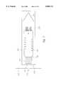
- a multi-detector array assembly 402comprises a scintillator assembly 802, a multi-channel photomultiplier tube 416, a fiber optic link 412, integral alignment means, and an outer detector housing 418.
- Multi-detector array assembly 402preferably contains a light tight outer detector housing 418 to minimize any noise which may be generated by stray light.
- X-raysenter the multi-detector array assembly 402 through an x-ray window 404 in lead shield 406.
- X-ray window 404is preferably circular and about 1.91 cm (0.75 in) in diameter to permit a directed beam of x-rays to strike the scintillator array 112 while attenuating scattered x-rays.
- a light shield 408is preferably employed to shield the assembly from ambient light.
- the light shield 408may be made of a thin sheet of aluminum or beryllium chosen to attenuate light without substantially attenuating the x-rays, and is preferably 0.0125 cm thick.
- Scintillator assembly 802is preferably positioned such that the pseudo-circular scintillator array 112 is substantially aligned with the x-ray window 404.
- scintillator assembly 802which is outlined in phantom, is preferably attached to adjuster plate 323 with attachment screws 312, 313, 314 and 315. If BGO scintillators are employed, then a heating element 410, preferably a resistive heating element designed to keep the scintillator assembly 820 at an operating temperature of about 100° C., is positioned on the adjuster plate 323.
- the preferred scintillator assembly 802is described more fully in connection with the detailed description of FIGS. 4 and 5.
- An optical linkpreferably a fiber optic imaging taper 412, directs light photons emerging out of the bottom 414 of the scintillator assembly 802 to a multi-channel photomultiplier tube (PMT) 416.
- the preferred fiber optic imaging taper 412is available from Collimated Holes of Campbell, Calif., and has a circular input aperture diameter of approximately 2.03 cm (0.8 in) and a circular output aperture diameter of approximately 3.38 cm (1.33 in). Fiber optic imaging taper 412 matches each scintillator crystal pitch dimension (0.06") to that of the PMT 416 (0.10"), i.e., it has a magnification of 1.667 times.
- High viscosity optical coupling fluid available from Dow Corning (Type 200) with a refractive index approximately matching that of the glassmay be used at the two faces of the taper as an optical coupling medium to maximize the light transfer efficiency from the scintillator crystals 170 to the fiber optic imaging taper 412 and from the fiber optic imaging taper 412 to the PMT input face 424.
- the preferred PMT 416is a 96-channel tube (one channel corresponding to each scintillator crystal 170) model number XP 1724A available from the Philips Corporation. As shown in FIGS. 10 and 11, it preferably has a fiber optic face plate 340 so that the spatial arrangement of the scintillator array 112 is accurately carried through to the PMT photocathode located in the PMT on the other face of the faceplate.
- 96 photocathode elements 339are arranged in a pseudo-circular array in the center of the front face of PMT 416.
- Each photocathode elementis preferably square in shape with dimensions of 2.54 mm ⁇ 2.54 mm.
- An x-ray photon striking one of the scintillators 170produces many light photons, some of which are coupled to the PMT photocathode. This produces a corresponding electron pulse at the photocathode and the pulse is amplified in one channel of the PMT dynode structure up to approximately 1,000,000 times.
- the pseudo-circular array of 96 photocathode elementscreates a light-sensitive circular area 338 on the PMT 416 with a diameter of 30.5 mm. It is this light sensitive area 338 that interfaces with the tapered fiber optic bundle 412.
- Each PMT photocathode element 339has a corresponding electrical output connector 342. When light photons reach the PMT 416, the photocathode elements 339 generates signals which are amplified by the dynode structure and output at PMT connectors 342.
- Adjuster plate 323is attached to PMT mount 426 with three shoulder screws 420, 428, and 430 through alignment holes with diameters larger than the diameter of the shoulder screws. Shoulder screws 420, 428, and 430 are spring loaded (shown in FIG. 8) so that adjuster plate 323 is fixed because of the tension applied by the shoulder screw springs, but can be further manipulated for positioning purposes.
- y-axis positioning screw 422Attached to the side of detector housing 418 is y-axis positioning screw 422.
- Spring loaded return pin 423is located on the side of detector housing 418 directly opposite y-axis positioning screw 422 and biasing the adjuster plate against the y-axis positioning screw 422. Rotation of y-axis positioning screw 422 will move the adjuster plate 323 along the y-axis, causing a corresponding shift in the y-axis position of the attached scintillator array 112.
- x-axis positioning screw 425 and spring loaded return pin 427operate in an identical manner to adjust the x-axis positioning of the scintillator array 112.
- a tongue 409 of outer detector housing 418is positioned between rotational positioning screw 306 and spring loaded return pin 309.
- the tongue 409is placed between the ends of rotational bracket 411, and is biased by the tension of the loaded return pin 309 against rotational positioning screw 306. Adjusting the rotational positioning screw 306 will cause a rotational shift in the tongue 409 of the outer detector housing 418, causing a corresponding shift in the attached adjuster plate 323, which results in an adjustment of the scintillator array 112 with respect to the PMT 416.
- FIGS. 12 and 13Another embodiment of a multi-detector array assembly 350 depicted with alternate alignment means is shown in FIGS. 12 and 13.
- X-raysenter through a circular x-ray window 351, preferably 1.91 cm in diameter, which is located in an x-ray opaque detector housing 360.
- a light shield(not shown) can be disposed adjacent the x-ray window to shield the assembly from ambient light.
- a scintillator assembly 802preferably the scintillator assembly described more fully in connection with the detailed description of FIGS. 4 and 5, is rigidly bolted to the interior surface of the detector housing 360.
- Detector housing 360with the scintillator assembly 802 rigidly attached, is attached to the PMT mount 362 with four shoulder screws 364, 366, 368, and 370 (370 not shown) through alignment holes with diameters larger than the diameter of the shoulder screws.
- Shoulder screws 364, 366, 368, and 370are spring loaded so that detector housing 360 moves axially, because of the tension applied by the shoulder screw springs, to maintain the scintillator assembly 802 in contact with fiber optic imaging taper 412 and to maintain the fiber optic imaging taper 412 in contact with the input face of the PMT 416.
- Adjustment collar 372preferably formed with a cylindrical outer surface and a tapered inner surface, is positioned within the upper aperture of PMT mount 362.
- Fiber optic imaging taper 412preferably inserted along the inner tapered surface of the adjustment collar 320, is mounted between the scintillator array 112 and the input face of the PMT 416.
- the preferred fiber optic imaging taper 412was described more fully in connection with the detailed description of FIG. 8.
- PMT 416preferably the photomultiplier tube described more fully in connection with the detailed description of FIGS. 10 and 11, is rigidly bolted into the lower stepped opening of PMT mount 312.
- alignment screws 352, 354, 356, and 358are preferably employed to align the fiber optic imaging taper 412 within the multi-detector array assembly 350.
- the alignment screwsare disposed within four apertures equidistantly placed through the upper walls of the PMT mount 362.
- the alignment screwsare positioned such that they form solid contact with the adjustment collar 372, which is yoked around the fiber optic imaging taper 412.
- a viscous silicon optical-coupling mediumis applied along the two faces of the fiber optic imaging taper 412.
- alignment screws 352, 354, 356, and 358are manipulated such that pressure is applied to the alignment collar 372 in the required alignment direction. This repositions the alignment collar 372, forming a corresponding repositioning of the fiber optic imaging taper 412.
- an x-ray shield 440formed of an x-ray opaque material and containing x-ray transmissive windows, is disposed before the input face of the scintillator array 112. As shown in FIG.
- the preferred x-ray shield 440is a circular disc formed of lead with four equally sized x-ray transmissive windows (442, 444, 446, and 448), equidistantly spaced along the outer perimeter, such that each x-ray transmissive window corresponds to an equivalent number and placement of scintillator elements 170 along the outer edge of the preferred scintillator array 112 (outlined in dashed lines).
- the line 2--2will be referred to as the y-axis and the line 3--3 will be referred to as the x-axis.
- An x-ray sourceis positioned such that an even spread of x-rays is directed at the x-ray shield 440.
- Suitable measurement meansare connected to the output leads of the PMT 416 to measure the electrical signals produced by the specific PMT channels which correspond to scintillator elements 170 located adjacent to the x-ray transmissive windows 442, 444, 445, and 448.
- Such measurement meansmay comprise, for example an amplifier and a comparator to count the number of light photons detected by the PMT 416, employing photon counting circuitry described more fully in U.S. Pat. No. 5,651,047, which has been incorporated herein by reference in its entirety.
- Suitable meansare preferably employed to amplify and balance the output signals from the PMT channels, as described more fully in U.S. Pat. No. 5,651,047, which has been incorporated herein by reference in its entirety.
- the alignment procedureis initiated by a directed emission of x-rays spread evenly across the face of the x-ray shield 440. If the scintillator elements are optimally aligned with their corresponding PMT channels along the y-axis, then the output signals from the PMT channels which correspond to the scintillator elements 170 adjacent to x-ray windows 442 and 446 should be maximized. To effect a y-axis alignment, the scintillator array 112 is positionally adjusted along the y-axis in the manner described more fully in connection with FIGS. 12 and 13, and after each adjustment, another directed emission of x-rays is evenly spread across the face of x-ray shield 440.
- the x-axis alignment processinvolves the manipulation of the scintillator array 112 along the x-axis, in the manner more fully described in connection with FIGS. 8-9, until further beams of x-rays directed at the x-ray shield 440 produce maximum levels of output signals measured for the PMT channels corresponding to the x-axis scintillation elements 170 adjacent x-ray windows 444 and 448.
- the next stepis to rotationally align the scintillator array 112.
- the processis initiated by an even spread of x-rays directed at the outer face of x-ray shield 440.
- the scintillator array 112is rotationally adjusted to the optimal positioning, then the level of visible light transferred to the PMT 416 should be at a maximum. Therefore, the scintillator array 112 is manipulated rotationally in the manner described in connection with FIGS. 8-9, and a directed beam of x-rays are emitted after each adjustment, until any further rotational manipulations would result in less visible light being detected by the PMT 416.
- the y-axis and x-axis alignment procedurescan be repeated after the rotational adjustments have been made to correct x or y-axis misalignments introduced by the rotational adjustments.
- An alternate alignment methodcomprises the use of a high-power microscope to optimally align the scintillator elements 170 with their corresponding photomultiplier tube channels.
- the input faces of the scintillator elements 170are polished as well as the output faces.
- the multi-detector array assembly 350is mounted to an alignment stand and a microscope is placed along the input face of the scintillator crystal array 112. To effect the optimal alignment, the microscope is initially positioned over the input face of one of the scintillator elements 170 along the outer perimeter of the scintillator array 112. The positioning screws within the multi-detector array 350 are manipulated, in the manner described in connection with FIG.
Landscapes
- Health & Medical Sciences (AREA)
- Life Sciences & Earth Sciences (AREA)
- Physics & Mathematics (AREA)
- High Energy & Nuclear Physics (AREA)
- Molecular Biology (AREA)
- Engineering & Computer Science (AREA)
- Medical Informatics (AREA)
- Spectroscopy & Molecular Physics (AREA)
- General Physics & Mathematics (AREA)
- Pathology (AREA)
- Surgery (AREA)
- Optics & Photonics (AREA)
- Biophysics (AREA)
- Radiology & Medical Imaging (AREA)
- Biomedical Technology (AREA)
- Heart & Thoracic Surgery (AREA)
- Nuclear Medicine, Radiotherapy & Molecular Imaging (AREA)
- Animal Behavior & Ethology (AREA)
- General Health & Medical Sciences (AREA)
- Public Health (AREA)
- Veterinary Medicine (AREA)
- Chemical & Material Sciences (AREA)
- Crystallography & Structural Chemistry (AREA)
- General Engineering & Computer Science (AREA)
- Measurement Of Radiation (AREA)
Abstract
Description
Claims (16)
Priority Applications (1)
| Application Number | Priority Date | Filing Date | Title |
|---|---|---|---|
| US09/152,079US6060713A (en) | 1993-04-05 | 1998-09-11 | X-ray detector |
Applications Claiming Priority (6)
| Application Number | Priority Date | Filing Date | Title |
|---|---|---|---|
| US4274293A | 1993-04-05 | 1993-04-05 | |
| PCT/US1994/003737WO1994023458A2 (en) | 1993-04-05 | 1994-04-05 | X-ray detector for a low dosage scanning beam digital x-ray imaging system |
| US37550195A | 1995-01-17 | 1995-01-17 | |
| US08/387,292US5550378A (en) | 1993-04-05 | 1995-02-10 | X-ray detector |
| US08/703,044US5808306A (en) | 1993-04-05 | 1996-08-26 | X-ray detector |
| US09/152,079US6060713A (en) | 1993-04-05 | 1998-09-11 | X-ray detector |
Related Parent Applications (1)
| Application Number | Title | Priority Date | Filing Date |
|---|---|---|---|
| US08/703,044ContinuationUS5808306A (en) | 1993-04-05 | 1996-08-26 | X-ray detector |
Publications (1)
| Publication Number | Publication Date |
|---|---|
| US6060713Atrue US6060713A (en) | 2000-05-09 |
Family
ID=26719572
Family Applications (3)
| Application Number | Title | Priority Date | Filing Date |
|---|---|---|---|
| US08/387,292Expired - LifetimeUS5550378A (en) | 1993-04-05 | 1995-02-10 | X-ray detector |
| US08/703,044Expired - LifetimeUS5808306A (en) | 1993-04-05 | 1996-08-26 | X-ray detector |
| US09/152,079Expired - LifetimeUS6060713A (en) | 1993-04-05 | 1998-09-11 | X-ray detector |
Family Applications Before (2)
| Application Number | Title | Priority Date | Filing Date |
|---|---|---|---|
| US08/387,292Expired - LifetimeUS5550378A (en) | 1993-04-05 | 1995-02-10 | X-ray detector |
| US08/703,044Expired - LifetimeUS5808306A (en) | 1993-04-05 | 1996-08-26 | X-ray detector |
Country Status (1)
| Country | Link |
|---|---|
| US (3) | US5550378A (en) |
Cited By (19)
| Publication number | Priority date | Publication date | Assignee | Title |
|---|---|---|---|---|
| WO2002017329A1 (en)* | 2000-08-24 | 2002-02-28 | Lenslet Ltd. | Optical content addressable memory |
| US6553092B1 (en)* | 2000-03-07 | 2003-04-22 | Koninklijke Philips Electronics, N.V. | Multi-layer x-ray detector for diagnostic imaging |
| US6608300B2 (en)* | 2001-11-16 | 2003-08-19 | Encoder Products Co. | Modular encoder rotation sensing |
| US20040159792A1 (en)* | 1998-03-25 | 2004-08-19 | Cti Pet Systems, Inc. | Scintillation detector array for encoding the energy, position and time coordinates of gamma ray interactions |
| EP1283426A3 (en)* | 2001-08-09 | 2005-04-06 | Philips Intellectual Property & Standards GmbH | X ray detector with heating device |
| US20050123097A1 (en)* | 2002-04-08 | 2005-06-09 | Nanodynamics, Inc. | High quantum energy efficiency X-ray tube and targets |
| WO2005103759A1 (en)* | 2004-04-20 | 2005-11-03 | Forimtech Sa | Large area radiation imaging detector |
| US20070138381A1 (en)* | 2005-12-16 | 2007-06-21 | Meschko John T | Optical encoder system |
| RU2330612C1 (en)* | 2006-11-14 | 2008-08-10 | Государственное учреждение здравоохранения города Москвы "Научно-практический центр медицинской радиологии" Департамента здравоохранения города Москвы | Estimator for modulation transfer function of x-ray image detector according to "sharp edge" method |
| EP1995608A4 (en)* | 2006-03-13 | 2011-12-14 | Hitachi Metals Ltd | Radiation detector and method for producing the same |
| US8258483B1 (en) | 2011-05-05 | 2012-09-04 | Ut-Battelle, Llc | High spatial resolution particle detectors |
| US20130100345A1 (en)* | 2011-10-24 | 2013-04-25 | Siemens Medical Solutions Usa, Inc. | Imaging System Warp Correction with Phantom Assembly |
| US8520800B2 (en) | 2010-08-09 | 2013-08-27 | Triple Ring Technologies, Inc. | Method and apparatus for radiation resistant imaging |
| US9001962B2 (en) | 2012-12-20 | 2015-04-07 | Triple Ring Technologies, Inc. | Method and apparatus for multiple X-ray imaging applications |
| US9217719B2 (en) | 2013-01-10 | 2015-12-22 | Novaray Medical, Inc. | Method and apparatus for improved sampling resolution in X-ray imaging systems |
| US9520263B2 (en) | 2013-02-11 | 2016-12-13 | Novaray Medical Inc. | Method and apparatus for generation of a uniform-profile particle beam |
| US20190178821A1 (en)* | 2017-12-11 | 2019-06-13 | Rapiscan Systems, Inc. | X-Ray Tomography Inspection Systems and Methods |
| WO2023091435A1 (en)* | 2021-11-16 | 2023-05-25 | Lumafield | Shrouded x-ray device |
| US12405392B1 (en) | 2022-05-03 | 2025-09-02 | Triad National Security, Llc | Electroplated materials and array design for scintillators |
Families Citing this family (72)
| Publication number | Priority date | Publication date | Assignee | Title |
|---|---|---|---|---|
| US5719400A (en)* | 1995-08-07 | 1998-02-17 | The Regents Of The University Of California | High resolution detector array for gamma-ray imaging |
| JP3235717B2 (en)* | 1995-09-28 | 2001-12-04 | キヤノン株式会社 | Photoelectric conversion device and X-ray imaging device |
| US5933473A (en) | 1996-04-04 | 1999-08-03 | Hitachi, Ltd. | Non-destructive inspection apparatus and inspection system using it |
| DE19647235A1 (en)* | 1996-11-15 | 1998-05-20 | Martin Garg | Multi-channel medical dosimeter |
| US5970199A (en) | 1996-12-11 | 1999-10-19 | Act Communications, Inc. | Frame for supporting fiber optic cable splices |
| EP0974149B1 (en)* | 1997-04-08 | 2006-12-27 | XRT Limited | High resolution x-ray imaging of very small objects |
| US6278115B1 (en)* | 1998-08-28 | 2001-08-21 | Annistech, Inc. | X-ray inspection system detector with plastic scintillating material |
| US6118854A (en)* | 1998-10-06 | 2000-09-12 | Cardiac Mariners, Inc. | Method of making x-ray beam hardening filter and assembly |
| US6208709B1 (en) | 1998-10-06 | 2001-03-27 | Cardiac Mariners, Inc. | Detection processing system |
| US6183139B1 (en) | 1998-10-06 | 2001-02-06 | Cardiac Mariners, Inc. | X-ray scanning method and apparatus |
| US6234671B1 (en) | 1998-10-06 | 2001-05-22 | Cardiac Mariners, Inc. | X-ray system with scanning beam x-ray source below object table |
| EP1119292A4 (en)* | 1998-10-06 | 2004-10-06 | Nexray Inc | Image reconstruction method and apparatus |
| US6157703A (en)* | 1998-10-06 | 2000-12-05 | Cardiac Mariners, Inc. | Beam hardening filter for x-ray source |
| US6118853A (en)* | 1998-10-06 | 2000-09-12 | Cardiac Mariners, Inc. | X-ray target assembly |
| US6198802B1 (en) | 1998-10-06 | 2001-03-06 | Cardiac Mariners, Inc. | Scanning beam x-ray source and assembly |
| US6175611B1 (en) | 1998-10-06 | 2001-01-16 | Cardiac Mariners, Inc. | Tiered detector assembly |
| US6534773B1 (en)* | 1998-11-09 | 2003-03-18 | Photon Imaging, Inc. | Radiation imaging detector and method of fabrication |
| DE50015405D1 (en)* | 1999-11-30 | 2008-11-27 | Philips Intellectual Property | Grid for the absorption of X-rays |
| US6292529B1 (en)* | 1999-12-15 | 2001-09-18 | Analogic Corporation | Two-dimensional X-ray detector array for CT applications |
| US6661867B2 (en)* | 2001-10-19 | 2003-12-09 | Control Screening, Llc | Tomographic scanning X-ray inspection system using transmitted and compton scattered radiation |
| CA2514425A1 (en)* | 2003-02-10 | 2004-08-26 | Digirad Corporation | Scintillator assembly with pre-formed reflector |
| US7138638B2 (en)* | 2003-11-20 | 2006-11-21 | Juni Jack E | Edge effects treatment for crystals |
| US7286639B2 (en)* | 2003-12-12 | 2007-10-23 | Ge Medical Systems Global Technology Company, Llc | Focal spot sensing device and method in an imaging system |
| US7023950B1 (en)* | 2004-02-11 | 2006-04-04 | Martin Annis | Method and apparatus for determining the position of an x-ray cone beam produced by a scanning electron beam |
| US7626174B2 (en)* | 2004-06-25 | 2009-12-01 | Koninklijke Philips Electronics N.V. | X-ray detector with correction for scattered radiation |
| DE102005008619A1 (en)* | 2005-02-23 | 2006-09-07 | Leica Microsystems Cms Gmbh | Microscope, has detector device and probe between which detection beam path extends, where detector device is arranged as introducible and collectively interchangeable detector module in detection beam path |
| US20060208200A1 (en)* | 2005-02-23 | 2006-09-21 | Leica Microsystems Cms Gmbh | Microscope and detector module |
| US20070269018A1 (en)* | 2006-05-03 | 2007-11-22 | Geoffrey Harding | Systems and methods for generating a diffraction profile |
| KR101124549B1 (en)* | 2007-04-24 | 2012-03-20 | 가부시끼가이샤 도시바 | Radiography measuring device and radiography measuring method |
| US7620143B2 (en)* | 2007-06-16 | 2009-11-17 | General Electric Company | Detector array and system |
| CA2732759C (en)* | 2007-08-03 | 2015-07-21 | Pulsetor, Llc | Pileup rejection in an energy-dispersive radiation spectrometry system |
| WO2009020866A1 (en)* | 2007-08-03 | 2009-02-12 | Pulsetor, Llc | Adapting a high-performance pulse processor to an existing spectrometry system |
| US8039787B2 (en)* | 2007-08-03 | 2011-10-18 | Pulsetor, Llc | Digital pulse processor slope correction |
| US7639777B2 (en)* | 2008-02-26 | 2009-12-29 | United Technologies Corp. | Computed tomography systems and related methods involving forward collimation |
| US20090213984A1 (en)* | 2008-02-26 | 2009-08-27 | United Technologies Corp. | Computed Tomography Systems and Related Methods Involving Post-Target Collimation |
| US8238521B2 (en)* | 2008-03-06 | 2012-08-07 | United Technologies Corp. | X-ray collimators, and related systems and methods involving such collimators |
| US20090225954A1 (en)* | 2008-03-06 | 2009-09-10 | United Technologies Corp. | X-Ray Collimators, and Related Systems and Methods Involving Such Collimators |
| US7876875B2 (en)* | 2008-04-09 | 2011-01-25 | United Technologies Corp. | Computed tomography systems and related methods involving multi-target inspection |
| US7888647B2 (en)* | 2008-04-30 | 2011-02-15 | United Technologies Corp. | X-ray detector assemblies and related computed tomography systems |
| US20090274264A1 (en)* | 2008-04-30 | 2009-11-05 | United Technologies Corp. | Computed Tomography Systems and Related Methods Involving Localized Bias |
| US7807973B2 (en)* | 2008-08-01 | 2010-10-05 | Pulsetor, Llc | Pileup rejection in an energy-dispersive radiation spectrometry system |
| KR20110088294A (en)* | 2010-01-28 | 2011-08-03 | 서준석 | Plastic Scintillator, Scintillation Detector and Medical Image Diagnosis System |
| US8509380B2 (en) | 2010-03-19 | 2013-08-13 | The Board Of Trustees Of The Leland Stanford Junior University | Inverse geometry volume computed tomography systems |
| JP2014510274A (en)* | 2011-03-03 | 2014-04-24 | サン−ゴバン セラミックス アンド プラスティクス,インコーポレイティド | System, method and apparatus for imaging array using non-uniform partition walls |
| US9186524B2 (en) | 2011-06-29 | 2015-11-17 | Triple Ring Technologies, Inc. | Method and apparatus for localized X-ray radiation treatment |
| JP5750763B2 (en)* | 2011-09-09 | 2015-07-22 | 国立研究開発法人産業技術総合研究所 | Sample storage cell for X-ray microscope and observation method of X-ray microscope image |
| RU2536788C1 (en)* | 2013-07-08 | 2014-12-27 | Сергей Иванович Мирошниченко | Composite fibre optic connector and x-rays receiver on its base (versions) |
| WO2016172291A1 (en)* | 2015-04-23 | 2016-10-27 | Fermi Research Alliance, Llc | Monocrystal-based microchannel plate image intensifier |
| WO2017030557A1 (en)* | 2015-08-17 | 2017-02-23 | Orthogrid Systems, Inc. | A surgical positioning system, apparatus and method of use |
| US10799197B2 (en)* | 2016-03-14 | 2020-10-13 | Koninklijke Philips N.V. | Round flat detector for X-ray imaging |
| US9855445B2 (en) | 2016-04-01 | 2018-01-02 | Varian Medical Systems, Inc. | Radiation therapy systems and methods for delivering doses to a target volume |
| US10549117B2 (en) | 2017-07-21 | 2020-02-04 | Varian Medical Systems, Inc | Geometric aspects of radiation therapy planning and treatment |
| US11590364B2 (en) | 2017-07-21 | 2023-02-28 | Varian Medical Systems International Ag | Material inserts for radiation therapy |
| US10092774B1 (en) | 2017-07-21 | 2018-10-09 | Varian Medical Systems International, AG | Dose aspects of radiation therapy planning and treatment |
| US11712579B2 (en) | 2017-07-21 | 2023-08-01 | Varian Medical Systems, Inc. | Range compensators for radiation therapy |
| US10843011B2 (en) | 2017-07-21 | 2020-11-24 | Varian Medical Systems, Inc. | Particle beam gun control systems and methods |
| US10183179B1 (en) | 2017-07-21 | 2019-01-22 | Varian Medical Systems, Inc. | Triggered treatment systems and methods |
| CN111556776B (en)* | 2017-11-16 | 2022-09-02 | 瓦里安医疗系统公司 | Increased beam output and dynamic field shaping for radiation therapy systems |
| CN107765287B (en)* | 2017-11-20 | 2023-11-14 | 中国工程物理研究院激光聚变研究中心 | Nuclear leakage detector and method for detecting pollution source by using same |
| US10910188B2 (en) | 2018-07-25 | 2021-02-02 | Varian Medical Systems, Inc. | Radiation anode target systems and methods |
| DE102019202452A1 (en) | 2019-02-22 | 2020-08-27 | Carl Zeiss Industrielle Messtechnik Gmbh | X-ray examination arrangement and method for operating an X-ray examination arrangement |
| US10814144B2 (en) | 2019-03-06 | 2020-10-27 | Varian Medical Systems, Inc. | Radiation treatment based on dose rate |
| US10918886B2 (en) | 2019-06-10 | 2021-02-16 | Varian Medical Systems, Inc. | Flash therapy treatment planning and oncology information system having dose rate prescription and dose rate mapping |
| CN112114347B (en)* | 2019-06-21 | 2024-05-17 | 清华大学 | Apparatus and method for manufacturing scintillator detectors |
| US12390662B2 (en) | 2020-04-02 | 2025-08-19 | Siemens Healthineers International Ag | System and method for proton therapy treatment planning with proton energy and spot optimization |
| US11865361B2 (en) | 2020-04-03 | 2024-01-09 | Varian Medical Systems, Inc. | System and method for scanning pattern optimization for flash therapy treatment planning |
| US11541252B2 (en) | 2020-06-23 | 2023-01-03 | Varian Medical Systems, Inc. | Defining dose rate for pencil beam scanning |
| US11957934B2 (en) | 2020-07-01 | 2024-04-16 | Siemens Healthineers International Ag | Methods and systems using modeling of crystalline materials for spot placement for radiation therapy |
| US12064645B2 (en) | 2020-07-02 | 2024-08-20 | Siemens Healthineers International Ag | Methods and systems used for planning radiation treatment |
| US20220120921A1 (en)* | 2020-10-16 | 2022-04-21 | Brown Universtiy | High resolution x-ray detector system |
| US20240037774A1 (en)* | 2022-07-29 | 2024-02-01 | Lawrence Livermore National Security, Llc | Three-dimensional scintillation detection technique for radiation detection |
| WO2025050041A1 (en)* | 2023-08-31 | 2025-03-06 | Mayo Foundation For Medical Education And Research | X-ray detector with x-ray fluorescent components |
Citations (62)
| Publication number | Priority date | Publication date | Assignee | Title |
|---|---|---|---|---|
| US2667585A (en)* | 1951-02-15 | 1954-01-26 | Hartford Nat Bank & Trust Co | Device for producing screening images of body sections |
| US2837657A (en)* | 1954-11-19 | 1958-06-03 | Logetronics Inc | Radiographic method and apparatus |
| US2942109A (en)* | 1956-07-19 | 1960-06-21 | Persa R Bell | Scintillation spectrometer |
| US3048698A (en)* | 1959-03-11 | 1962-08-07 | Picker X Ray Corp | Scintillation camera |
| US3106640A (en)* | 1960-10-06 | 1963-10-08 | William H Oldendorf | Radiant energy apparatus for investigating selected areas of the interior of objectsobscured by dense material |
| US3499146A (en)* | 1966-10-10 | 1970-03-03 | Albert G Richards | Variable depth laminagraphy with means for highlighting the detail of selected lamina |
| US3591806A (en)* | 1970-03-17 | 1971-07-06 | Atomic Energy Commission | Multicrystal tomographic scanner for mapping thin cross section of radioactivity in an organ of the human body |
| US3742236A (en)* | 1970-10-07 | 1973-06-26 | A Richards | Method and apparatus for variable depth laminagraphy |
| US3746872A (en)* | 1971-07-27 | 1973-07-17 | Nuclear Chicago Corp | Tomography technique in which a single recording film retains spatial information to permit constructing all planar sections of object |
| US3778614A (en)* | 1968-08-23 | 1973-12-11 | Emi Ltd | Method and apparatus for measuring x- or {65 -radiation absorption or transmission at plural angles and analyzing the data |
| US3780291A (en)* | 1971-07-07 | 1973-12-18 | American Science & Eng Inc | Radiant energy imaging with scanning pencil beam |
| US3809886A (en)* | 1971-11-26 | 1974-05-07 | Cfc Products | Dynamic tomography with movable table |
| US3818220A (en)* | 1971-11-03 | 1974-06-18 | A Richards | Variable depth laminagraphy |
| US3855471A (en)* | 1973-04-20 | 1974-12-17 | Konan Camera Res Inst | Radiograph recording apparatus |
| FR2237206A1 (en)* | 1973-07-13 | 1975-02-07 | Anvar | Scintillator crystal for a gamma camera - with multiple crystal prismatic units |
| US3873834A (en)* | 1971-01-29 | 1975-03-25 | Philips Corp | Method of producing three-dimensional images from a series of individual images in different perspectives |
| US3919556A (en)* | 1974-05-15 | 1975-11-11 | Gen Electric | Gamma camera |
| US3922552A (en)* | 1974-02-15 | 1975-11-25 | Robert S Ledley | Diagnostic X-ray systems |
| US3924129A (en)* | 1973-04-25 | 1975-12-02 | Emi Ltd | Method and apparatus for constructing a representation of a planar{3 s slice of body exposed to penetrating radiation |
| US3925660A (en)* | 1972-05-08 | 1975-12-09 | Richard D Albert | Selectable wavelength X-ray source, spectrometer and assay method |
| US3936639A (en)* | 1974-05-01 | 1976-02-03 | Raytheon Company | Radiographic imaging system for high energy radiation |
| US3944833A (en)* | 1968-08-23 | 1976-03-16 | E M I Limited | Apparatus for examining a body by radiation such as X or gamma radiation |
| US3946234A (en)* | 1973-08-31 | 1976-03-23 | E M I Limited | Apparatus for examining bodies by means of penetrating radiation |
| US3949229A (en)* | 1974-06-24 | 1976-04-06 | Albert Richard D | X-ray scanning method and apparatus |
| US3973128A (en)* | 1973-08-18 | 1976-08-03 | Emi Limited | Tomography |
| US3979594A (en)* | 1969-01-27 | 1976-09-07 | Anger Hal O | Tomographic gamma ray apparatus and method |
| US3983397A (en)* | 1972-05-08 | 1976-09-28 | Albert Richard D | Selectable wavelength X-ray source |
| US4002917A (en)* | 1974-08-28 | 1977-01-11 | Emi Limited | Sources of X-radiation |
| US4010370A (en)* | 1974-11-13 | 1977-03-01 | Emi Limited | Computerized tomography apparatus with means to periodically displace radiation source |
| US4017730A (en)* | 1974-05-01 | 1977-04-12 | Raytheon Company | Radiographic imaging system for high energy radiation |
| US4031395A (en)* | 1975-02-21 | 1977-06-21 | Emi Limited | Radiography |
| US4032787A (en)* | 1974-06-24 | 1977-06-28 | Albert Richard D | Method and apparatus producing plural images of different contrast range by x-ray scanning |
| US4048496A (en)* | 1972-05-08 | 1977-09-13 | Albert Richard D | Selectable wavelength X-ray source, spectrometer and assay method |
| US4052619A (en)* | 1974-02-15 | 1977-10-04 | Emi Limited | Method and apparatus for measuring and analyzing radiation transmitted at plural angles |
| US4066902A (en)* | 1974-03-23 | 1978-01-03 | Emi Limited | Radiography with detector compensating means |
| US4144457A (en)* | 1976-04-05 | 1979-03-13 | Albert Richard D | Tomographic X-ray scanning system |
| US4149076A (en)* | 1976-04-05 | 1979-04-10 | Albert Richard D | Method and apparatus producing plural images of different contrast range by X-ray scanning |
| US4196351A (en)* | 1977-06-03 | 1980-04-01 | Albert Richard David | Scanning radiographic apparatus |
| US4234794A (en)* | 1977-12-22 | 1980-11-18 | Statia De Verificare Si Intretinere A Aparaturii Medicale | Installation of radiodiagnosis with sweep |
| US4259582A (en)* | 1979-11-02 | 1981-03-31 | Albert Richard D | Plural image signal system for scanning x-ray apparatus |
| US4259583A (en)* | 1979-05-03 | 1981-03-31 | Albert Richard D | Image region selector for a scanning X-ray system |
| US4260885A (en)* | 1978-02-24 | 1981-04-07 | Albert Richard D | Selectable wavelength X-ray source, spectrometer and assay method |
| US4321473A (en)* | 1977-06-03 | 1982-03-23 | Albert Richard David | Focusing radiation collimator |
| US4323779A (en)* | 1977-06-03 | 1982-04-06 | Albert Richard David | Scanning radiographic method |
| US4383327A (en)* | 1980-12-01 | 1983-05-10 | University Of Utah | Radiographic systems employing multi-linear arrays of electronic radiation detectors |
| US4464776A (en)* | 1983-06-23 | 1984-08-07 | Technicare Corporation | Multiplexing signal processing channels in a CT scanner with rotating source |
| US4519092A (en)* | 1982-10-27 | 1985-05-21 | Albert Richard D | Scanning x-ray spectrometry method and apparatus |
| US4573179A (en)* | 1984-05-29 | 1986-02-25 | Imatron, Inc. | Scanned projection radiography using high speed computed tomographic scanning system |
| US4573183A (en)* | 1984-06-29 | 1986-02-25 | General Electric Company | X-Ray image brightness control |
| US4592080A (en)* | 1983-07-29 | 1986-05-27 | Siemens Aktiengesellschaft | Computer tomograph |
| US4730350A (en)* | 1986-04-21 | 1988-03-08 | Albert Richard D | Method and apparatus for scanning X-ray tomography |
| US4831263A (en)* | 1987-05-14 | 1989-05-16 | Hamamatsu Photonics Kabushiki Kaisha | Position-sensitive radiation detector |
| US4853540A (en)* | 1985-06-05 | 1989-08-01 | Fuji Photo Film Co., Ltd. | Apparatus for recording a radiation image of an object on a stimulable phosphor sheet to facilitate later reconstruction of an arbitrary tomographic image of the object |
| US4873708A (en)* | 1987-05-11 | 1989-10-10 | General Electric Company | Digital radiographic imaging system and method therefor |
| US4946238A (en)* | 1984-01-27 | 1990-08-07 | University Of Pittsburgh | Fiber optic coupler |
| US5029338A (en)* | 1987-10-19 | 1991-07-02 | Siemens Aktiengesellschaft | X-ray diagnostics installation |
| US5132539A (en)* | 1991-08-29 | 1992-07-21 | General Electric Company | Planar X-ray imager having a moisture-resistant sealing structure |
| US5153438A (en)* | 1990-10-01 | 1992-10-06 | General Electric Company | Method of forming an x-ray imaging array and the array |
| US5187369A (en)* | 1990-10-01 | 1993-02-16 | General Electric Company | High sensitivity, high resolution, solid state x-ray imaging device with barrier layer |
| US5198673A (en)* | 1992-01-23 | 1993-03-30 | General Electric Company | Radiation image detector with optical gain selenium photosensors |
| US5267296A (en)* | 1992-10-13 | 1993-11-30 | Digiray Corporation | Method and apparatus for digital control of scanning X-ray imaging systems |
| US5401969A (en)* | 1993-07-21 | 1995-03-28 | Scintillation Technologies Corporation | Scintillation camera |
Family Cites Families (37)
| Publication number | Priority date | Publication date | Assignee | Title |
|---|---|---|---|---|
| US2730566A (en)* | 1949-12-27 | 1956-01-10 | Bartow Beacons Inc | Method and apparatus for x-ray fluoroscopy |
| US3114832A (en)* | 1960-07-28 | 1963-12-17 | Radiation Counter Lab Inc | X-ray spectroscopic system comprising plural sources, filters, fluorescent radiators, and comparative detectors |
| US3617740A (en)* | 1968-10-08 | 1971-11-02 | High Voltage Engineering Corp | Modular electron source for uniformly irradiating the surface of a product |
| US3605750A (en)* | 1969-04-07 | 1971-09-20 | David S Sheridan | X-ray tip catheter |
| US3593243A (en)* | 1969-06-02 | 1971-07-13 | High Voltage Power Corp | Electrical induction apparatus |
| US3611032A (en)* | 1969-06-16 | 1971-10-05 | High Voltage Engineering Corp | Electromagnetic induction apparatus for high-voltage power generation |
| BE785906A (en)* | 1971-07-12 | 1973-01-08 | High Voltage Power Corp | ELECTROMAGNETIC INDUCTION DEVICE |
| FR2166625A5 (en)* | 1971-12-31 | 1973-08-17 | Thomson Csf | |
| US4206361A (en)* | 1972-05-17 | 1980-06-03 | E M I Limited | Radiography |
| US4104526A (en)* | 1973-04-24 | 1978-08-01 | Albert Richard D | Grid-cathode controlled X-ray tube |
| US3992631A (en)* | 1975-02-27 | 1976-11-16 | International Diagnostic Technology, Inc. | Fluorometric system, method and test article |
| US4007375A (en)* | 1975-07-14 | 1977-02-08 | Albert Richard D | Multi-target X-ray source |
| FR2443741A1 (en)* | 1978-12-05 | 1980-07-04 | Labo Electronique Physique | IMPROVEMENT WITH THE ANGER SCINTILLATION CAMERA |
| US4465540A (en)* | 1979-05-03 | 1984-08-14 | Albert Richard D | Method of manufacture of laminate radiation collimator |
| US4288697A (en)* | 1979-05-03 | 1981-09-08 | Albert Richard D | Laminate radiation collimator |
| JPS5789849A (en)* | 1980-11-21 | 1982-06-04 | Tokyo Shibaura Electric Co | X-ray photographing apparatus |
| JPS5892980A (en)* | 1981-11-30 | 1983-06-02 | Toshiba Corp | Two-dimensional radiation detector |
| JPS58210582A (en)* | 1982-05-31 | 1983-12-07 | Shimadzu Corp | radiation position detector |
| US4532425A (en)* | 1982-08-04 | 1985-07-30 | Elscint Inc. | Gamma camera with light guide having greater index of refraction |
| US4646338A (en)* | 1983-08-01 | 1987-02-24 | Kevex Corporation | Modular portable X-ray source with integral generator |
| US4577637A (en)* | 1984-07-13 | 1986-03-25 | Argon Medical Corp. | Flexible metal radiopaque indicator and plugs for catheters |
| US4694480A (en)* | 1985-07-30 | 1987-09-15 | Kevex Corporation | Hand held precision X-ray source |
| US4802195A (en)* | 1986-02-25 | 1989-01-31 | General Electric Company | Device for method for manipulating a part |
| US4967121A (en)* | 1987-05-27 | 1990-10-30 | Rca Licensing Corporation | Isolating high voltage transformer for video apparatus |
| US4796637A (en)* | 1987-06-17 | 1989-01-10 | Victory Engineering Company | Radiopaque marker for stereotaxic catheter |
| US4974929A (en)* | 1987-09-22 | 1990-12-04 | Baxter International, Inc. | Fiber optical probe connector for physiologic measurement devices |
| JPH0255904U (en)* | 1988-10-18 | 1990-04-23 | ||
| US5099128A (en)* | 1989-03-17 | 1992-03-24 | Roger Stettner | High resolution position sensitive detector |
| US5045072A (en)* | 1989-06-13 | 1991-09-03 | Cordis Corporation | Catheter having highly radiopaque, flexible tip |
| US4990785A (en)* | 1989-07-03 | 1991-02-05 | The Curators Of The University Of Missouri | Radiation imaging apparatus and methods |
| US5185773A (en)* | 1991-07-19 | 1993-02-09 | General Motors Corporation | Method and apparatus for nondestructive selective determination of a metal |
| US5189599A (en)* | 1991-08-14 | 1993-02-23 | Zenith Electronics Corporation | High voltage regulator for an integrated horizontal sweep system |
| JP2544858B2 (en)* | 1991-12-04 | 1996-10-16 | インターナショナル・ビジネス・マシーンズ・コーポレイション | High voltage generation circuit |
| US5231654A (en)* | 1991-12-06 | 1993-07-27 | General Electric Company | Radiation imager collimator |
| US5231655A (en)* | 1991-12-06 | 1993-07-27 | General Electric Company | X-ray collimator |
| US5203777A (en)* | 1992-03-19 | 1993-04-20 | Lee Peter Y | Radiopaque marker system for a tubular device |
| US5237598A (en)* | 1992-04-24 | 1993-08-17 | Albert Richard D | Multiple image scanning X-ray method and apparatus |
- 1995
- 1995-02-10USUS08/387,292patent/US5550378A/ennot_activeExpired - Lifetime
- 1996
- 1996-08-26USUS08/703,044patent/US5808306A/ennot_activeExpired - Lifetime
- 1998
- 1998-09-11USUS09/152,079patent/US6060713A/ennot_activeExpired - Lifetime
Patent Citations (63)
| Publication number | Priority date | Publication date | Assignee | Title |
|---|---|---|---|---|
| US2667585A (en)* | 1951-02-15 | 1954-01-26 | Hartford Nat Bank & Trust Co | Device for producing screening images of body sections |
| US2837657A (en)* | 1954-11-19 | 1958-06-03 | Logetronics Inc | Radiographic method and apparatus |
| US2942109A (en)* | 1956-07-19 | 1960-06-21 | Persa R Bell | Scintillation spectrometer |
| US3048698A (en)* | 1959-03-11 | 1962-08-07 | Picker X Ray Corp | Scintillation camera |
| US3106640A (en)* | 1960-10-06 | 1963-10-08 | William H Oldendorf | Radiant energy apparatus for investigating selected areas of the interior of objectsobscured by dense material |
| US3499146A (en)* | 1966-10-10 | 1970-03-03 | Albert G Richards | Variable depth laminagraphy with means for highlighting the detail of selected lamina |
| US3944833A (en)* | 1968-08-23 | 1976-03-16 | E M I Limited | Apparatus for examining a body by radiation such as X or gamma radiation |
| US3778614A (en)* | 1968-08-23 | 1973-12-11 | Emi Ltd | Method and apparatus for measuring x- or {65 -radiation absorption or transmission at plural angles and analyzing the data |
| US3979594A (en)* | 1969-01-27 | 1976-09-07 | Anger Hal O | Tomographic gamma ray apparatus and method |
| US3591806A (en)* | 1970-03-17 | 1971-07-06 | Atomic Energy Commission | Multicrystal tomographic scanner for mapping thin cross section of radioactivity in an organ of the human body |
| US3742236A (en)* | 1970-10-07 | 1973-06-26 | A Richards | Method and apparatus for variable depth laminagraphy |
| US3873834A (en)* | 1971-01-29 | 1975-03-25 | Philips Corp | Method of producing three-dimensional images from a series of individual images in different perspectives |
| US3780291A (en)* | 1971-07-07 | 1973-12-18 | American Science & Eng Inc | Radiant energy imaging with scanning pencil beam |
| US3746872A (en)* | 1971-07-27 | 1973-07-17 | Nuclear Chicago Corp | Tomography technique in which a single recording film retains spatial information to permit constructing all planar sections of object |
| US3818220A (en)* | 1971-11-03 | 1974-06-18 | A Richards | Variable depth laminagraphy |
| US3809886A (en)* | 1971-11-26 | 1974-05-07 | Cfc Products | Dynamic tomography with movable table |
| US3925660A (en)* | 1972-05-08 | 1975-12-09 | Richard D Albert | Selectable wavelength X-ray source, spectrometer and assay method |
| US3983397A (en)* | 1972-05-08 | 1976-09-28 | Albert Richard D | Selectable wavelength X-ray source |
| US4048496A (en)* | 1972-05-08 | 1977-09-13 | Albert Richard D | Selectable wavelength X-ray source, spectrometer and assay method |
| US3855471A (en)* | 1973-04-20 | 1974-12-17 | Konan Camera Res Inst | Radiograph recording apparatus |
| US3924129A (en)* | 1973-04-25 | 1975-12-02 | Emi Ltd | Method and apparatus for constructing a representation of a planar{3 s slice of body exposed to penetrating radiation |
| FR2237206A1 (en)* | 1973-07-13 | 1975-02-07 | Anvar | Scintillator crystal for a gamma camera - with multiple crystal prismatic units |
| US3973128A (en)* | 1973-08-18 | 1976-08-03 | Emi Limited | Tomography |
| US3946234A (en)* | 1973-08-31 | 1976-03-23 | E M I Limited | Apparatus for examining bodies by means of penetrating radiation |
| US4052619A (en)* | 1974-02-15 | 1977-10-04 | Emi Limited | Method and apparatus for measuring and analyzing radiation transmitted at plural angles |
| US3922552A (en)* | 1974-02-15 | 1975-11-25 | Robert S Ledley | Diagnostic X-ray systems |
| US4066902A (en)* | 1974-03-23 | 1978-01-03 | Emi Limited | Radiography with detector compensating means |
| US3936639A (en)* | 1974-05-01 | 1976-02-03 | Raytheon Company | Radiographic imaging system for high energy radiation |
| US4017730A (en)* | 1974-05-01 | 1977-04-12 | Raytheon Company | Radiographic imaging system for high energy radiation |
| US3919556A (en)* | 1974-05-15 | 1975-11-11 | Gen Electric | Gamma camera |
| US4032787A (en)* | 1974-06-24 | 1977-06-28 | Albert Richard D | Method and apparatus producing plural images of different contrast range by x-ray scanning |
| US4057745A (en)* | 1974-06-24 | 1977-11-08 | Albert Richard D | Scanning X-ray source |
| US3949229A (en)* | 1974-06-24 | 1976-04-06 | Albert Richard D | X-ray scanning method and apparatus |
| US4002917A (en)* | 1974-08-28 | 1977-01-11 | Emi Limited | Sources of X-radiation |
| US4010370A (en)* | 1974-11-13 | 1977-03-01 | Emi Limited | Computerized tomography apparatus with means to periodically displace radiation source |
| US4031395A (en)* | 1975-02-21 | 1977-06-21 | Emi Limited | Radiography |
| US4149076A (en)* | 1976-04-05 | 1979-04-10 | Albert Richard D | Method and apparatus producing plural images of different contrast range by X-ray scanning |
| US4144457A (en)* | 1976-04-05 | 1979-03-13 | Albert Richard D | Tomographic X-ray scanning system |
| US4196351A (en)* | 1977-06-03 | 1980-04-01 | Albert Richard David | Scanning radiographic apparatus |
| US4321473A (en)* | 1977-06-03 | 1982-03-23 | Albert Richard David | Focusing radiation collimator |
| US4323779A (en)* | 1977-06-03 | 1982-04-06 | Albert Richard David | Scanning radiographic method |
| US4234794A (en)* | 1977-12-22 | 1980-11-18 | Statia De Verificare Si Intretinere A Aparaturii Medicale | Installation of radiodiagnosis with sweep |
| US4260885A (en)* | 1978-02-24 | 1981-04-07 | Albert Richard D | Selectable wavelength X-ray source, spectrometer and assay method |
| US4259583A (en)* | 1979-05-03 | 1981-03-31 | Albert Richard D | Image region selector for a scanning X-ray system |
| US4259582A (en)* | 1979-11-02 | 1981-03-31 | Albert Richard D | Plural image signal system for scanning x-ray apparatus |
| US4383327A (en)* | 1980-12-01 | 1983-05-10 | University Of Utah | Radiographic systems employing multi-linear arrays of electronic radiation detectors |
| US4519092A (en)* | 1982-10-27 | 1985-05-21 | Albert Richard D | Scanning x-ray spectrometry method and apparatus |
| US4464776A (en)* | 1983-06-23 | 1984-08-07 | Technicare Corporation | Multiplexing signal processing channels in a CT scanner with rotating source |
| US4592080A (en)* | 1983-07-29 | 1986-05-27 | Siemens Aktiengesellschaft | Computer tomograph |
| US4946238A (en)* | 1984-01-27 | 1990-08-07 | University Of Pittsburgh | Fiber optic coupler |
| US4573179A (en)* | 1984-05-29 | 1986-02-25 | Imatron, Inc. | Scanned projection radiography using high speed computed tomographic scanning system |
| US4573183A (en)* | 1984-06-29 | 1986-02-25 | General Electric Company | X-Ray image brightness control |
| US4853540A (en)* | 1985-06-05 | 1989-08-01 | Fuji Photo Film Co., Ltd. | Apparatus for recording a radiation image of an object on a stimulable phosphor sheet to facilitate later reconstruction of an arbitrary tomographic image of the object |
| US4730350A (en)* | 1986-04-21 | 1988-03-08 | Albert Richard D | Method and apparatus for scanning X-ray tomography |
| US4873708A (en)* | 1987-05-11 | 1989-10-10 | General Electric Company | Digital radiographic imaging system and method therefor |
| US4831263A (en)* | 1987-05-14 | 1989-05-16 | Hamamatsu Photonics Kabushiki Kaisha | Position-sensitive radiation detector |
| US5029338A (en)* | 1987-10-19 | 1991-07-02 | Siemens Aktiengesellschaft | X-ray diagnostics installation |
| US5153438A (en)* | 1990-10-01 | 1992-10-06 | General Electric Company | Method of forming an x-ray imaging array and the array |
| US5187369A (en)* | 1990-10-01 | 1993-02-16 | General Electric Company | High sensitivity, high resolution, solid state x-ray imaging device with barrier layer |
| US5132539A (en)* | 1991-08-29 | 1992-07-21 | General Electric Company | Planar X-ray imager having a moisture-resistant sealing structure |
| US5198673A (en)* | 1992-01-23 | 1993-03-30 | General Electric Company | Radiation image detector with optical gain selenium photosensors |
| US5267296A (en)* | 1992-10-13 | 1993-11-30 | Digiray Corporation | Method and apparatus for digital control of scanning X-ray imaging systems |
| US5401969A (en)* | 1993-07-21 | 1995-03-28 | Scintillation Technologies Corporation | Scintillation camera |
Non-Patent Citations (28)
| Title |
|---|
| Barrett et al., "The Theory of Image Formation, Detection, and Processing", vol. 2, Radiological Imaging, published at least by Dec., 1981, pp. 368-371. |
| Barrett et al., The Theory of Image Formation, Detection, and Processing , vol. 2, Radiological Imaging , published at least by Dec., 1981, pp. 368 371.* |
| Cosslett et al., X Ray Microscopy , at least by Dec. 1960, pp. 216 369.* |
| Cosslett et al., X-Ray Microscopy, at least by Dec. 1960, pp. 216-369. |
| Curry et al., Christensen s Physics of Diagnostic Radiology , Fourth Edition, Lea & Febiger, 1990, pp. 1 522.* |
| Curry et al., Christensen's Physics of Diagnostic Radiology, Fourth Edition, Lea & Febiger, 1990, pp. 1-522. |
| Digiray, "Digiray's Reverse Geometry X-ray System", Digiray Marketing Brochure, at least by Dec. 1992, pp. 1-2. |
| Digiray, Digiray s Reverse Geometry X ray System , Digiray Marketing Brochure , at least by Dec. 1992, pp. 1 2.* |
| Dolby et al., "A Spectrometer System for Long Wavelength X-ray Emission Microanalysis", at least by Dec. 1960, X-ray Microscopy and X-ray Microanalysis, pp. 351-357. |
| Dolby et al., A Spectrometer System for Long Wavelength X ray Emission Microanalysis , at least by Dec. 1960, X ray Microscopy and X ray Microanalysis , pp. 351 357.* |
| George L. Clark, The Encyclopedia of X rays and Gamma Rays , at least by Dec. 1963, pp.608 617.* |
| George L. Clark, The Encyclopedia of X-rays and Gamma Rays, at least by Dec. 1963, pp.608-617. |
| Gray, "Application of Optical Instrumentation in Medicine VII", Proceedings of the Society of Photo-Optical Instrumentation Engineers, Mar. 25-27, 1979, vol. 173, pp. 88-95. |
| Gray, Application of Optical Instrumentation in Medicine VII , Proceedings of the Society of Photo Optical Instrumentation Engineers, Mar. 25 27, 1979, vol. 173, pp. 88 95.* |
| Howard Pattee, Jr., "Possibilities of the Scanning X-Ray Microscope", at least by Dec., 1957, X-Ray Microscopy and Microradiography, pp. 367-375. |
| Howard Pattee, Jr., Possibilities of the Scanning X Ray Microscope , at least by Dec., 1957, X Ray Microscopy and Microradiography , pp. 367 375.* |
| Lewis Etter, "The Science of Ionizing Radiation", at least by Dec., 1965, pp. 546-548. |
| Lewis Etter, The Science of Ionizing Radiation , at least by Dec., 1965, pp. 546 548.* |
| Moon, "Amplifying and Intensifying the Fluroscopic Image by Means of a Scanning X-ray Tube", Oct. 6, 1950, Science, vol. 112, pp. 389-395. |
| Moon, Amplifying and Intensifying the Fluroscopic Image by Means of a Scanning X ray Tube , Oct. 6, 1950, Science , vol. 112, pp. 389 395.* |
| Nixon, "High-Resolution X-ray Projection Microscopy", Nov. 1955, Proceedings of the Royal Society of London, vol. 232, pp. 475-484. |
| Nixon, High Resolution X ray Projection Microscopy , Nov. 1955, Proceedings of the Royal Society of London , vol. 232, pp. 475 484.* |
| Pattee, "The Scanning X-ray Microscope", Jan. 1953, Journal Opt. Soc. Amer., vol. 43, pp. 61-62. |
| Pattee, The Scanning X ray Microscope , Jan. 1953, Journal Opt. Soc. Amer ., vol. 43, pp. 61 62.* |
| Philips Photonics, "xP1700 Multichannel Photomultipliers", xP1700 Family of Multi-channel Photomultipliers--Philips Photonic Handbook, at least by Dec. 1993, pp. 1-15. |
| Philips Photonics, xP1700 Multichannel Photomultipliers , xP1700 Family of Multi channel Photomultipliers Philips Photonic Handbook , at least by Dec. 1993, pp. 1 15.* |
| Swinth et al., "Biomedical Probe Using a Fiber-Optic Coupled Scintillator", Mar./Apr. 1976, Medical Physics, vol. 3, No. 2, pp. 109-112. |
| Swinth et al., Biomedical Probe Using a Fiber Optic Coupled Scintillator , Mar./Apr. 1976, Medical Physics , vol. 3, No. 2, pp. 109 112.* |
Cited By (24)
| Publication number | Priority date | Publication date | Assignee | Title |
|---|---|---|---|---|
| US20040159792A1 (en)* | 1998-03-25 | 2004-08-19 | Cti Pet Systems, Inc. | Scintillation detector array for encoding the energy, position and time coordinates of gamma ray interactions |
| US6553092B1 (en)* | 2000-03-07 | 2003-04-22 | Koninklijke Philips Electronics, N.V. | Multi-layer x-ray detector for diagnostic imaging |
| WO2002017329A1 (en)* | 2000-08-24 | 2002-02-28 | Lenslet Ltd. | Optical content addressable memory |
| EP1283426A3 (en)* | 2001-08-09 | 2005-04-06 | Philips Intellectual Property & Standards GmbH | X ray detector with heating device |
| US6608300B2 (en)* | 2001-11-16 | 2003-08-19 | Encoder Products Co. | Modular encoder rotation sensing |
| US7180981B2 (en) | 2002-04-08 | 2007-02-20 | Nanodynamics-88, Inc. | High quantum energy efficiency X-ray tube and targets |
| US20050123097A1 (en)* | 2002-04-08 | 2005-06-09 | Nanodynamics, Inc. | High quantum energy efficiency X-ray tube and targets |
| WO2005103759A1 (en)* | 2004-04-20 | 2005-11-03 | Forimtech Sa | Large area radiation imaging detector |
| US20070138381A1 (en)* | 2005-12-16 | 2007-06-21 | Meschko John T | Optical encoder system |
| EP1995608A4 (en)* | 2006-03-13 | 2011-12-14 | Hitachi Metals Ltd | Radiation detector and method for producing the same |
| RU2330612C1 (en)* | 2006-11-14 | 2008-08-10 | Государственное учреждение здравоохранения города Москвы "Научно-практический центр медицинской радиологии" Департамента здравоохранения города Москвы | Estimator for modulation transfer function of x-ray image detector according to "sharp edge" method |
| US8520800B2 (en) | 2010-08-09 | 2013-08-27 | Triple Ring Technologies, Inc. | Method and apparatus for radiation resistant imaging |
| US8258483B1 (en) | 2011-05-05 | 2012-09-04 | Ut-Battelle, Llc | High spatial resolution particle detectors |
| US9158008B2 (en) | 2011-05-05 | 2015-10-13 | Ut-Battelle, Llc | High spatial resolution particle detectors |
| US20130100345A1 (en)* | 2011-10-24 | 2013-04-25 | Siemens Medical Solutions Usa, Inc. | Imaging System Warp Correction with Phantom Assembly |
| US8988601B2 (en)* | 2011-10-24 | 2015-03-24 | Siemens Medical Solutions Usa, Inc. | Imaging system warp correction with phantom assembly |
| US9001962B2 (en) | 2012-12-20 | 2015-04-07 | Triple Ring Technologies, Inc. | Method and apparatus for multiple X-ray imaging applications |
| US9217719B2 (en) | 2013-01-10 | 2015-12-22 | Novaray Medical, Inc. | Method and apparatus for improved sampling resolution in X-ray imaging systems |
| US9733198B2 (en) | 2013-01-10 | 2017-08-15 | Novaray Medical, Inc. | Method and apparatus for improved sampling resolution in X-ray imaging systems |
| US9520263B2 (en) | 2013-02-11 | 2016-12-13 | Novaray Medical Inc. | Method and apparatus for generation of a uniform-profile particle beam |
| US9953798B2 (en) | 2013-02-11 | 2018-04-24 | Novaray Medical, Inc. | Method and apparatus for generation of a uniform-profile particle beam |
| US20190178821A1 (en)* | 2017-12-11 | 2019-06-13 | Rapiscan Systems, Inc. | X-Ray Tomography Inspection Systems and Methods |
| WO2023091435A1 (en)* | 2021-11-16 | 2023-05-25 | Lumafield | Shrouded x-ray device |
| US12405392B1 (en) | 2022-05-03 | 2025-09-02 | Triad National Security, Llc | Electroplated materials and array design for scintillators |
Also Published As
| Publication number | Publication date |
|---|---|
| US5550378A (en) | 1996-08-27 |
| US5808306A (en) | 1998-09-15 |
Similar Documents
| Publication | Publication Date | Title |
|---|---|---|
| US6060713A (en) | X-ray detector | |
| JP3569526B2 (en) | X-ray detector for low dose scanning beam type digital X-ray imaging system | |
| US5144141A (en) | Photodetector scintillator radiation imager | |
| EP0808465B1 (en) | Scanning-beam x-ray imaging system | |
| US4415808A (en) | Scintillation detector array employing zig-zag plates | |
| US8017906B2 (en) | Slit and slot scan, SAR, and compton devices and systems for radiation imaging | |
| US4426721A (en) | X-ray intensifier detector system for x-ray electronic radiography | |
| KR20040088495A (en) | radiation detector arrangement comprising multiple line detector units | |
| KR100806068B1 (en) | Radiation Detection Apparatus and Method | |
| US20020074505A1 (en) | Detection of radiation and positron emission tomography | |
| AU2002218600A1 (en) | Detection of radiation and positron emission tomography | |
| US5338937A (en) | Radiation imaging device having an enlarged uniform field of view | |
| US3683185A (en) | Radiation imaging apparatus | |
| US5382798A (en) | Ionizing radiation sensor used in a system of radiographic imaging | |
| AU2001262881A1 (en) | Radiation detection apparatus and method | |
| JP2001507453A (en) | Detection head and collimator for gamma camera | |
| US5171998A (en) | Gamma ray imaging detector | |
| EP0556901B1 (en) | Apparatus for detecting high energy radiation | |
| Gamble et al. | Linear position‐sensitive x‐ray detector incorporating a self‐scanning photodiode array | |
| Puertolas et al. | An ISPA-camera for gamma rays | |
| JPH10319122A (en) | Radiation image pick-up device | |
| US20030136913A1 (en) | Radiation detector with a detection field comprising scintillators and photodiodes | |
| EP1330664A1 (en) | Scintillator based detection apparatus and method using two-dimensional matrix of light detecting elements | |
| JPH02132396A (en) | radiation detector |
Legal Events
| Date | Code | Title | Description |
|---|---|---|---|
| STCF | Information on status: patent grant | Free format text:PATENTED CASE | |
| CC | Certificate of correction | ||
| AS | Assignment | Owner name:NEXRAY, INC., CALIFORNIA Free format text:CHANGE OF NAME;ASSIGNOR:CARDIAC MARINERS, INC.;REEL/FRAME:013542/0626 Effective date:20000407 | |
| FPAY | Fee payment | Year of fee payment:4 | |
| FEPP | Fee payment procedure | Free format text:PAYOR NUMBER ASSIGNED (ORIGINAL EVENT CODE: ASPN); ENTITY STATUS OF PATENT OWNER: SMALL ENTITY | |
| AS | Assignment | Owner name:WIJCIK, LYNDA, CALIFORNIA Free format text:ASSIGNMENT AND AFFIDAVIT RE;ASSIGNOR:NEXRAY, INC.;REEL/FRAME:017073/0895 Effective date:20050630 | |
| AS | Assignment | Owner name:CARDIAC MARINERS, INCORPORATED, CALIFORNIA Free format text:ASSIGNMENT OF ASSIGNORS INTEREST;ASSIGNORS:SKILLICORN, BRIAN;PASTRONE, GIOVANNI;REEL/FRAME:017275/0462 Effective date:19950210 | |
| AS | Assignment | Owner name:NOVARAY, INC., CALIFORNIA Free format text:ASSIGNMENT OF ASSIGNORS INTEREST;ASSIGNOR:WIJCIK, LYNDA;REEL/FRAME:017833/0738 Effective date:20060523 | |
| FPAY | Fee payment | Year of fee payment:8 | |
| FPAY | Fee payment | Year of fee payment:12 | |
| SULP | Surcharge for late payment | Year of fee payment:11 | |
| AS | Assignment | Owner name:AIRDRIE PARTNERS I, LP, NEW YORK Free format text:ASSIGNMENT OF ASSIGNORS INTEREST;ASSIGNOR:NOVARAY MEDICAL, INC.;REEL/FRAME:043408/0101 Effective date:20170622 |