US6060705A - Electrospray and atmospheric pressure chemical ionization sources - Google Patents
Electrospray and atmospheric pressure chemical ionization sourcesDownload PDFInfo
- Publication number
- US6060705A US6060705AUS08/988,491US98849197AUS6060705AUS 6060705 AUS6060705 AUS 6060705AUS 98849197 AUS98849197 AUS 98849197AUS 6060705 AUS6060705 AUS 6060705A
- Authority
- US
- United States
- Prior art keywords
- electrospray
- chamber
- electrical potential
- endplate
- solution
- Prior art date
- Legal status (The legal status is an assumption and is not a legal conclusion. Google has not performed a legal analysis and makes no representation as to the accuracy of the status listed.)
- Expired - Lifetime
Links
- 238000000065atmospheric pressure chemical ionisationMethods0.000titleabstractdescription15
- 238000000132electrospray ionisationMethods0.000titleabstractdescription7
- 238000000034methodMethods0.000claimsabstractdescription29
- 150000002500ionsChemical class0.000claimsdescription59
- 238000002663nebulizationMethods0.000claimsdescription21
- 238000004458analytical methodMethods0.000claimsdescription6
- 238000005040ion trapMethods0.000claimsdescription3
- 239000013626chemical specieSubstances0.000claims3
- 239000007788liquidSubstances0.000abstractdescription52
- 230000035945sensitivityEffects0.000abstractdescription8
- 238000005457optimizationMethods0.000abstractdescription7
- 239000007921spraySubstances0.000description24
- 239000000523sampleSubstances0.000description12
- 102000018832CytochromesHuman genes0.000description11
- 108010052832CytochromesProteins0.000description11
- 239000000243solutionSubstances0.000description11
- 238000001704evaporationMethods0.000description8
- 230000008020evaporationEffects0.000description7
- 230000005686electrostatic fieldEffects0.000description6
- 238000001819mass spectrumMethods0.000description6
- 230000015572biosynthetic processEffects0.000description4
- 239000006199nebulizerSubstances0.000description4
- 238000013024troubleshootingMethods0.000description4
- QTBSBXVTEAMEQO-UHFFFAOYSA-NAcetic acidChemical compoundCC(O)=OQTBSBXVTEAMEQO-UHFFFAOYSA-N0.000description3
- OKKJLVBELUTLKV-UHFFFAOYSA-NMethanolChemical compoundOCOKKJLVBELUTLKV-UHFFFAOYSA-N0.000description3
- 238000005251capillar electrophoresisMethods0.000description3
- 238000001035dryingMethods0.000description3
- 230000000694effectsEffects0.000description3
- 238000005421electrostatic potentialMethods0.000description3
- 238000004811liquid chromatographyMethods0.000description3
- 238000004519manufacturing processMethods0.000description3
- 238000005086pumpingMethods0.000description3
- 238000001228spectrumMethods0.000description3
- 238000004252FT/ICR mass spectrometryMethods0.000description2
- 238000000149argon plasma sinteringMethods0.000description2
- 230000007423decreaseEffects0.000description2
- 238000003795desorptionMethods0.000description2
- 238000010586diagramMethods0.000description2
- 238000007787electrohydrodynamic sprayingMethods0.000description2
- 239000011521glassSubstances0.000description2
- 238000005286illuminationMethods0.000description2
- 238000001802infusionMethods0.000description2
- 238000004949mass spectrometryMethods0.000description2
- 230000007935neutral effectEffects0.000description2
- 238000012552reviewMethods0.000description2
- 239000002904solventSubstances0.000description2
- 239000000126substanceSubstances0.000description2
- 230000000007visual effectEffects0.000description2
- 241000238634LibellulidaeSpecies0.000description1
- VYPSYNLAJGMNEJ-UHFFFAOYSA-NSilicium dioxideChemical compoundO=[Si]=OVYPSYNLAJGMNEJ-UHFFFAOYSA-N0.000description1
- 230000001133accelerationEffects0.000description1
- 238000013459approachMethods0.000description1
- 239000007864aqueous solutionSubstances0.000description1
- 239000003125aqueous solventSubstances0.000description1
- 238000000738capillary electrophoresis-mass spectrometryMethods0.000description1
- 238000000451chemical ionisationMethods0.000description1
- 150000001875compoundsChemical class0.000description1
- 238000012790confirmationMethods0.000description1
- 239000003989dielectric materialSubstances0.000description1
- 238000009826distributionMethods0.000description1
- 239000005350fused silica glassSubstances0.000description1
- 238000010348incorporationMethods0.000description1
- 238000002347injectionMethods0.000description1
- 239000007924injectionSubstances0.000description1
- 239000011810insulating materialSubstances0.000description1
- 239000012212insulatorSubstances0.000description1
- 230000001788irregularEffects0.000description1
- 238000002955isolationMethods0.000description1
- 238000004895liquid chromatography mass spectrometryMethods0.000description1
- 239000002184metalSubstances0.000description1
- 239000000203mixtureSubstances0.000description1
- 230000003287optical effectEffects0.000description1
- 230000035515penetrationEffects0.000description1
- 230000000541pulsatile effectEffects0.000description1
- 238000000926separation methodMethods0.000description1
- 238000012795verificationMethods0.000description1
- XLYOFNOQVPJJNP-UHFFFAOYSA-NwaterSubstancesOXLYOFNOQVPJJNP-UHFFFAOYSA-N0.000description1
Images


Classifications
- H—ELECTRICITY
- H01—ELECTRIC ELEMENTS
- H01J—ELECTRIC DISCHARGE TUBES OR DISCHARGE LAMPS
- H01J49/00—Particle spectrometers or separator tubes
- H01J49/02—Details
- H01J49/10—Ion sources; Ion guns
- H01J49/16—Ion sources; Ion guns using surface ionisation, e.g. field-, thermionic- or photo-emission
- H01J49/165—Electrospray ionisation
Definitions
- Atmospheric pressure ionization sourcesin particular Electrospray (ES) and Atmospheric Pressure Chemical Ionization (APCI) sources
- ESElectrospray
- APCIAtmospheric Pressure Chemical Ionization
- MSmass spectrometric
- ES and APCI sources interfaced to mass spectrometerscan produce ions from continuously flowing liquid samples and hence can serve as on-line detectors for Liquid Chromatography (LC) and Capillary Electrophoresis (CE) separation systems. Liquid samples can also be introduced by continuous infusion or sample injection into a continuously flowing solution.
- LCLiquid Chromatography
- CECapillary Electrophoresis
- Atmospheric Pressure Ionization sourcesin particular Electrospray and Atmospheric Pressure Chemical Ionization sources, interfaced to mass spectrometers have become widely used for the analysis of compounds found in solutions.
- ES/MS systemhave been described in U.S. Pat. Nos. 4,531,056, 4,542,293 and 4,209,696. The technique and its applications have been reviewed by Penn et. ala, Mass Spectrometry Reviews 1990, 9, 37-70 and by Smith et. al., Mass Spectrometry Reviews 1991, 10, 359-451.
- Electrospray and APCIhave been routinely used as ion sources for on-line LC/MS and CE/MS systems.
- Electrospray ionizationas diagrammatically illustrated in FIG. 1, sample bearing liquid is introduced into an atmospheric pressure bath gas through a tube which is generally sharpened at the exit end. A 3 to 6 kilovolt relative potential is applied between the ES liquid introduction tube or needle exit and the surrounding electrodes causing Electrospraying of the sample bearing liquid to occur.
- Charged liquid droplets formed in the Electrospray processevaporate as they pass through a counter current bath gas in the Electrospray chamber.
- the charged droplet evaporationleads to Rayleigh disintegration followed by further evaporation and shrinking of droplets. This process eventually leads to the desorption of ions directly from the smaller diameter charged droplet surface into the gas phase.
- a portion of the atmospheric pressure bath gas, entrained ions and charged liquid dropletsare swept into vacuum through an orifice or capillary annulus.
- the capillarymay be heated to further aid in droplet evaporation and ion desorption from the liquid droplets. Ions exiting the capillary enter vacuum through a free jet expansion and are accelerated and focused into a mass analyzer.
- Nebulization assist techniqueshave been applied to Electrospray to extend the range of operation while simplifying its use.
- High frequency ultrasonic nebulization applied at the Electrospray needle tiphas been used to assist the Electrospray droplet formation process.
- An ultrasonic nebulization assisted electrospray apparatusis manufactured by Analytica of Branford Inc.
- a pneumatic nebulization assisted electrosprayhas been reported first by Mack et al. J. of Chemical Physics, 1970, 62, 4977-4986 and later in U.S. Pat. No. 4,861,988.
- a commercial ES/MS quadrupole mass spectrometer produced by Sciexhas used a window located at the end of the cylindrical ES or pneumatic nebulization assisted ES source opposite to the ES endplate or vacuum orifice end.
- the internal diameter of this ES sourceis over 7 inches in diameter and the cylindrical side wall is maintained at ground potential.
- the endplate of this ES sourceis maintained at a potential within 1000 volts of ground.
- the windowis used to visualize the direction in which a pneumatic nebulizer assisted Electrospray, which produces coarse droplet sizes, is aimed during operation.
- the position of this viewing windowdoes not allow optimal viewing of the unassisted Electrospray spray.
- No conductive electrodewas placed inside this window to shield the ES source from the effects of space charge buildup on the inside dielectric surface of the window during operation.
- the droplet sizes produced by unassisted Electrosprayare a function of the liquid flow rate exiting the sharpened Electrospray liquid introduction tube tip.
- the liquid flow ratesare typically below 6 ⁇ l/min.
- the charged liquid droplet size distribution producedis monodisperse with a mean diameter of 2.93 microns.
- the Electrospray charged dropletsfan out due to space charge repulsion as they move away from the needle tip towards the counter electrode endplate. The moving droplets evaporate rapidly in the countercurrent drying gas and decrease in size as they approach the end plate.
- the droplet diameters produced in the low flow rate Electrospray plumeare so small that forward light scattering must be used to observe the spray plume.
- the Electrospray droplets produced initiallycan be seen from Mie scattering of visible, but as the droplets evaporate they enter the Rayleigh scattering regime for visible light.
- a Tyndall color spectracan be observed from a white light source scattered through an Electrospray droplet plume produced from liquid flows of 1 of 2 ⁇ l/min.
- the quality and stability of the unassisted Electrospraycan be quickly ascertained by a direct observation of the spray quality.
- the present inventionincludes the incorporation of windows or view ports located in positions around the side walls of an Electrospray chamber.
- the inventionincludes windows or view ports which are located on opposite sides of the ES chamber so a light source or viewing angle can be positioned to optimized observed scattering intensity from the ES spray plume. Voltages and needle position can be adjusted to visually optimize Electrospray performance during operation. If the MS signal becomes unstable or decreases, a quick visual observation of the ES plume can determine if the trouble is in the ES spray performance. For example a pulsatile liquid delivery pump or an air bubble emerging at the needle tip will temporarily interrupt the Electrospray process and the lack of spray can be visually observed.
- the side walls of the ES chamberare conductive to avoid space charge buildup of ions hitting the walls or windows along the side walls of the ES chamber.
- the conductive side wall electrodeusually cylindrical in shape and extending along most of the sidewall length of the ES chamber, is configured to allot viewing through the electrode into the ES source.
- the ES liquid introduction tube exit tipis maintained at a positive kilovolt potential relative to the counter electrode endplate and the surrounding cylindrical electrode or lens.
- the ES source configurationincludes countercurrent bath gas flow
- the ES chamber endplateis usually maintained between 0 to 1000 volts above the orifice or capillary entrance potential.
- the sidewall cylindrical shaped lens potentialis usually between 0 and positive 3000 volts relative to the endplate potential in the positive ion operating mode. The direction of the relative potentials would be reversed for the Electrospray production of ions with negative potential.
- the potentials of the ES chamber electrodesare generally set so that charged entities which leave the ES needle tip are directed and focused by the electrostatic field toward the orifice or capillary entrance into vacuum.
- positive or negative ion signal levelcan be significantly increased by increasing the potential difference between the cylindrical electrode and the ES liquid introduction tube while maintaining a constant differential between the ES liquid introduction tube and the endplate and capillary entrance electrodes.
- the mechanism for this increase in sensitivity when an apparent defocusing voltage is set on the cylindrical electrodeis not yet clearly understood.
- the increased sensitivity with increasing cylindrical electrode relative potentialappears to be more pronounced at higher liquid flow rates so the defocusing may help to fan out droplets for increased drying efficiency.
- the increased cylindrical electrode potential relative to the ES liquid introduction needle tip potentialmay cause an increase in the net charge density per droplet produced resulting in an increase in ES/MS sensitivity.
- windows in the sidewalls of an API source and configuring the source chamber to have a semitransparent sidewall electrode which allows viewing of the ES spray and the APCI corona discharge region during operationaids in and simplifies performance optimization and system troubleshooting during operation or either source type.
- the side wall electrodeis configured to run with a potential difference of up to thousands of volts between the ES liquid introduction needle tip, ES chamber endplate and orifice plate, higher signal intensities can be achieved in unassisted and nebulization assisted Electrospray operation.
- Increasing ES/MS sensitivity and the improving the convenience of API operationexpands the range of applications to which API/MS analysis can be routinely applied.
- FIG. 1is a diagram of an Electrospray ion source interfaced to a quadrupole mass spectrometer where four separate voltage elements are present in the ES chamber.
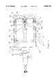
- FIG. 2is a cross section of the Electrospray chamber which includes a semitransparent side wall electrode and windows located on the sides of the ES chamber.
- FIG. 3is an external three dimensional view of the ES chamber with windows located on three sides.
- FIG. 4ais an ultrasonic nebulization assisted Electrospray/MS mass spectrum of Cytochrome C taken with a low voltage differential maintained between the cylindrical electrode and the ES liquid introduction needle tip.
- FIG. 4bis an ultrasonic nebulization assisted Electrospray/MS mass spectrum of Cytochrome C taken with a high voltage differential maintained between the cylindrical electrode and the ES liquid introduction needle tip.
- FIG. 5is a curve of Cytochrome C positive ion signal intensity versus the cylindrical electrode voltage.
- FIG. 6is a diagram of the APCI probe and corona discharge needle assembly mounted in an atmospheric pressure ion source chamber.
- Atmospheric Pressure Sourcesproduce ions at or near atmospheric pressure and deliver these ions into vacuum where they are accelerated and focused into a mass analyzer. Electrospray ionization produces charged droplets which, after evaporation, yield ions directly from liquid into the gas phase.
- Atmospheric Pressure Chemical Ionizationthe sample bearing liquid is first evaporated and sample gas phase ions are produced by chemical ionization charge exchange with solvent ions produced in a corona discharge region located in the atmospheric pressure source chamber.
- the Electrospray ion sourcewill initially be used as an example to describe the preferred embodiment of the invention. In Electrospray ionization, sample bearing liquid enters tube entrance 1 as shown in FIG. 1 and exits at the sharpened tube or needle tip 2.
- Electrospray liquid introduction tube tip 2is maintained at kilovolt potentials relative to surroundings ES chamber 3 electrodes 4, 5, and 6.
- Electrode 4is usually cylindrical in shape and extends the length of ES chamber 3.
- Electrode 5 known as the endplate electrodeincludes nosepiece 7 to shape electrostatic field lines in ES chamber 3 to achieve more efficient focusing of ions through aperture 8 and into capillary annulus entrance 10. Endplate nosepiece 7 also serves to direct the countercurrent bath gas flow to effect the efficient charged droplet evaporation.
- the capillary entrance end 6 electrodeis operated at a potential difference relative to endplate lens 5 to maximize ion focusing into capillary annulus entrance 10.
- charged dropletsare produced by maintaining a potential difference between tube tip 2 and surrounding electrodes 4, 5 and 6 is sufficiently large to cause a Taylor cone to form.
- the Electrosprayed charged liquid dropletswhich are produced near needle tip 2 move with the electrostatic field toward endplate nosepiece 7 and capillary entrance 6.
- the charged dropletsfan out to form spray 11 as they move away from needle tip 2.
- a heated bath gas as indicated by 12flows countercurrent to the charged droplet movement to aid droplet evaporation. Ions desorb from the evaporating charged liquid droplets and a portion of these ions are swept into vacuum along with neutral bath gas molecules through capillary 13 orifice or annulus 14.
- Capillary 13can be heated to aid in droplet evaporation alone or m combination with countercurrent bath gas 12. Shallow orifices have also been used in place of capillary 13 as an entrance into vacuum.
- Capillary 13 as illustratedis a glass or dielectric capillary with metalized or conductive ends.
- Mass analyzer 21is illustrated as a quadrupole mass filter, however, this could be a magnetic sector, ion trap, Time-Of-Flight (TOF) or Fourier Transform Ion Cyclotron Resonance (FT-ICR) mass analyzer as well.
- TOFTime-Of-Flight
- FT-ICRFourier Transform Ion Cyclotron Resonance
- FIG. 2shows a more detailed cross section view of Electrospray chamber 30 which includes ultrasonic nebulization assisted Electrospray liquid introduction tube assembly 31.
- assembly 31could be replaced by a pneumatic nebulization assisted Electrospray liquid introduction tube assembly or an unassisted Electrospray liquid introduction tube assembly.
- Sample bearing solutionexits at the sharpened tube tip 32 which is part of ultrasonic nebulizer assembly 31.
- tip 32is maintained at kilovolt potentials relative to ES chamber 30 counter electrodes 33, 34 and 35.
- the relative voltagesare set so that an Electrosprayed spray or plume 36 of charged droplets is driven by electrostatic forces toward the capillary entrance 37 against a heated counter current bath gas 38. If a stable Electrospray droplet formation process can not be maintained because higher liquid flow rates, aqueous or high conductivity solutions are exiting tip 32, then tip 32 can be mechanically vibrated at frequencies over 210 kilohertz to assist the charge droplet formation of the Electrospray process. Additionally focusing gas can be added at fitting 40 and exits through annulus 41 surrounding tip 32. This focusing gas flow can be added to limit the charged droplet drift in the radial direction as they move towards endplate nosepiece 32 and capillary entrance 42.
- pneumatic nebulizationcan be used at tip 32 to assist the Electrospray charged droplet formation by increasing the gas velocity exiting annulus 41.
- pneumatic nebulizationcan be used at tip 32 to assist the Electrospray charged droplet formation by increasing the gas velocity exiting annulus 41.
- windows 46 and 47have been incorporated into the side walls or the ES source housing 54 to permit viewing of spray 36 during source operation.
- a light source 48can be placed to illuminate spray plume 36 by passing light through window 47. With illumination from light 48 shining through window 47, spray plume 36 can be observed through window 46.
- the droplet sizes producedare small enough to show a Tyndall spectrum from white light scattering through Electrospray plume 36. The angle of viewing must be adjusted to receive the brightest plume 36 image so window 46 and 48 sizes are large enough to allow a range of viewing and illumination angles.
- Windows or view ports 46 and 47are mounted to ES chamber walls and sealed with seals 50 and 51 respectively to prevent gas or vapor from leaking out of ES source 28 during operation.
- window 47may include a drain or vent port 52.
- Cylindrical electrode 38is configured with semitransparent sections for those electrode areas which fall adjacent to windows 46 and 47.
- 33is a metal lens configured with screen or perforated sections with transparency over 60% adjacent to windows 46 and 47. The screens or perforated sections of lens 33 allow sufficient optical transparency for viewing but minimize any Electrostatic field penetration into ES source chamber 30 from any external electrostatic fields or charge build up on windows or insulating surfaces outside cylindrical lens 33. In the preferred embodiment shown in FIG.
- FIG. 3is a three dimensional view or ES chamber 60 with viewing windows 61, 62 and 63 located on three sides of ES chamber 60. Cylindrical lens 64 is shown with semitransparent perforated sections adjacent to each window location to allow viewing inside the ES source during operation.
- a light sourceis typically set to shine through bottom window 61 with the spray 36 observed through top window 63 during ES operation.
- capillary entrance lens 35can be operated at ground potential and the ES needle assembly maintained at ground potential during operation. Ions entering capillary annulus 14 can be driven uphill against the entrance kilovolt potential by gas collisions and delivered into vacuum at whatever voltage is set on capillary exit electrode 15. Consequently, the dielectric capillary entrance and exit potentials are decoupled and can be set independently of one another.
- FIG. 4ashows an Electrospray quadrupole mass spectrum of Cytochrome C (MW 12360). The spectrum was generated using ultrasonically assisted Electrospray with 200 ⁇ l/min continuous infusion of 1 picomole/ ⁇ l solution of Cytochrome C in 1:1 methanol: water and 0.1% acetic acid. The ES lens 32, 33, 34 and 35 potentials were set as listed above for a dielectric capillary, The intensity of multiply charged Cytochrome C peaks 70 and 71 shown in FIG.
- FIG. 4ais indicated on Y axis 72 with mass to charge (m/z) ratio given on X axis 73.
- the (M+15H) +15 Cytochrome C peak 70has an amplitude of roughly 1600.
- FIG. 4bshows a mass spectrum of Cytochrome C where cylindrical lens 33 potential was set a -6.0 KV and all other spray and voltage settings were identical to those set when the mass spectrum in FIG. 5a was taken.
- the (M+15 H) +15 Cytochroxne C peak 74amplitude has increased to 20,000, a factor of 12.5.
- the amplitude of related Cytochrome C amplitude peaks 75has also increased proportionally to m/z peak 74 FIG.
- FIG. 5shows the relationship 80 between signal intensity of Cytochrome C multiply charged peaks as cylindrical lens 33 potential is increased while holding all other Electrospray variables constant.
- Signal amplitudeis indicated by Y axis 81 with cylindrical lens 33 potential indicated along X axis 82.
- a significant increase in ion signalis observed as the cylindrical lens 33 potential is increased.
- the end data points on curve 80were taken from the mass spectrum shown in FIGS. 4a and 4b.
- An increase in signal intensityis achieved for both positive and negative ion operating modes when cylindrical lens 33 potential amplitude is increased. Increases in signal intensity can also be observed when pneumatic nebulization is used and cylindrical lens 33 potential amplitude is increased.
- Electrospray chamber 30because the relative potentials between electrostatic lens elements in Electrospray chamber 30 remain the same for both cases.
- Electrosprayis operated in an unassisted mode, the effect on signal improvement when cylindrical lens 33 potential amplitude is increased is more pronounced for larger tube tip 32 to endplate nosepiece 42 distances and a liquid flow rate increases.
- the mechanism for achieving higher signal when increasing cylindrical lens 33 potential amplitudeis not yet completely understood.
- One explanationmay be that the higher relative potentials between liquid introduction tube tip 32 and cylindrical lens 33 may result in higher net droplet charge density.
- the higher cylindrical lens 33 potentialmay help to spread out the charged liquid droplets to achieve more efficient drying for those droplets whose trajectories are along the ES chamber 30 centerline.
- FIG. 6Another embodiment of the invention is shown in FIG. 6 where APCI probe assembly 90 has replaced the ES liquid introduction tube assembly in API chamber 91.
- the API chamber assembly with windows 93 and 92 and a semitransparent cylindrical lens 94are similar to the configuration shown in FIG. 2 for ES source assembly 28.
- the window view portsallow observation of the corona discharge region 95, simplifying troubleshooting and optimization of the corona discharge formed at the tip of sharpened needle 96 during APCI source operation.
Landscapes
- Physics & Mathematics (AREA)
- Engineering & Computer Science (AREA)
- Plasma & Fusion (AREA)
- Chemical & Material Sciences (AREA)
- Analytical Chemistry (AREA)
- Other Investigation Or Analysis Of Materials By Electrical Means (AREA)
Abstract
Description
______________________________________ conductive dielectric capillary capillary or orifice ______________________________________ ESliquid introduction tip 32 0 V +5.0 KV Cylindrical lens 33 -3.0 KV +2.0 KV Endplate 34 -4.0 KV +1.0 KV Capillary entrance lens 35 -5.0 KV +100 V ______________________________________
______________________________________ conductive dielectric capillary capillary or orifice ______________________________________ ESliquid introduction tip 32 0 V +5.0 KV Cylidrical lens 33 -6.0 KV +1.0 KV Endplate 34 -4.0 KV +1.0 KV Capillary entrance lens 35 -5.0 KV +100 V ______________________________________
Claims (29)
Priority Applications (1)
| Application Number | Priority Date | Filing Date | Title |
|---|---|---|---|
| US08/988,491US6060705A (en) | 1997-12-10 | 1997-12-10 | Electrospray and atmospheric pressure chemical ionization sources |
Applications Claiming Priority (1)
| Application Number | Priority Date | Filing Date | Title |
|---|---|---|---|
| US08/988,491US6060705A (en) | 1997-12-10 | 1997-12-10 | Electrospray and atmospheric pressure chemical ionization sources |
Publications (1)
| Publication Number | Publication Date |
|---|---|
| US6060705Atrue US6060705A (en) | 2000-05-09 |
Family
ID=25534169
Family Applications (1)
| Application Number | Title | Priority Date | Filing Date |
|---|---|---|---|
| US08/988,491Expired - LifetimeUS6060705A (en) | 1997-12-10 | 1997-12-10 | Electrospray and atmospheric pressure chemical ionization sources |
Country Status (1)
| Country | Link |
|---|---|
| US (1) | US6060705A (en) |
Cited By (30)
| Publication number | Priority date | Publication date | Assignee | Title |
|---|---|---|---|---|
| US6245227B1 (en)* | 1998-09-17 | 2001-06-12 | Kionix, Inc. | Integrated monolithic microfabricated electrospray and liquid chromatography system and method |
| US20020172619A1 (en)* | 1998-09-17 | 2002-11-21 | Moon James E. | Integrated monolithic microfabricated electrospray and liquid chromatography system and method |
| US6486469B1 (en)* | 1999-10-29 | 2002-11-26 | Agilent Technologies, Inc. | Dielectric capillary high pass ion filter |
| WO2001091158A3 (en)* | 2000-05-22 | 2002-12-19 | Univ British Columbia | Atmospheric pressure ion lens for generating a larger and more stable ion flux |
| US6583407B1 (en)* | 1999-10-29 | 2003-06-24 | Agilent Technologies, Inc. | Method and apparatus for selective ion delivery using ion polarity independent control |
| US6596988B2 (en) | 2000-01-18 | 2003-07-22 | Advion Biosciences, Inc. | Separation media, multiple electrospray nozzle system and method |
| US6627882B2 (en) | 1999-12-30 | 2003-09-30 | Advion Biosciences, Inc. | Multiple electrospray device, systems and methods |
| US6633031B1 (en) | 1999-03-02 | 2003-10-14 | Advion Biosciences, Inc. | Integrated monolithic microfabricated dispensing nozzle and liquid chromatography-electrospray system and method |
| US6635868B2 (en)* | 2000-03-24 | 2003-10-21 | Anelva Corporation | Mass spectrometry apparatus |
| US6744041B2 (en) | 2000-06-09 | 2004-06-01 | Edward W Sheehan | Apparatus and method for focusing ions and charged particles at atmospheric pressure |
| US20040206901A1 (en)* | 2001-04-20 | 2004-10-21 | Chen David D.Y. | High throughput ion source with multiple ion sprayers and ion lenses |
| US6818889B1 (en)* | 2002-06-01 | 2004-11-16 | Edward W. Sheehan | Laminated lens for focusing ions from atmospheric pressure |
| US20050029442A1 (en)* | 2003-07-24 | 2005-02-10 | Zoltan Takats | Electrosonic spray ionization method and device for the atmospheric ionization of molecules |
| US6872940B1 (en)* | 2002-05-31 | 2005-03-29 | Thermo Finnigan Llc | Focusing ions using gas dynamics |
| US6888132B1 (en)* | 2002-06-01 | 2005-05-03 | Edward W Sheehan | Remote reagent chemical ionization source |
| US20050194530A1 (en)* | 2004-03-08 | 2005-09-08 | Rohan Thakur | Titanium ion transfer components for use in mass spectrometry |
| US6998605B1 (en)* | 2000-05-25 | 2006-02-14 | Agilent Technologies, Inc. | Apparatus for delivering ions from a grounded electrospray assembly to a vacuum chamber |
| US7081621B1 (en)* | 2004-11-15 | 2006-07-25 | Ross Clark Willoughby | Laminated lens for focusing ions from atmospheric pressure |
| US7095019B1 (en) | 2003-05-30 | 2006-08-22 | Chem-Space Associates, Inc. | Remote reagent chemical ionization source |
| WO2007008191A1 (en)* | 2005-07-06 | 2007-01-18 | Metara, Inc. | Nebulizer with plasma source |
| US20070114389A1 (en)* | 2005-11-08 | 2007-05-24 | Karpetsky Timothy P | Non-contact detector system with plasma ion source |
| US7568401B1 (en) | 2005-06-20 | 2009-08-04 | Science Applications International Corporation | Sample tube holder |
| US7586092B1 (en) | 2005-05-05 | 2009-09-08 | Science Applications International Corporation | Method and device for non-contact sampling and detection |
| US20100154568A1 (en)* | 2008-11-19 | 2010-06-24 | Roth Michael J | Analytical Instruments, Assemblies, and Methods |
| US7816646B1 (en) | 2003-06-07 | 2010-10-19 | Chem-Space Associates, Inc. | Laser desorption ion source |
| US8008617B1 (en) | 2007-12-28 | 2011-08-30 | Science Applications International Corporation | Ion transfer device |
| US8071957B1 (en) | 2009-03-10 | 2011-12-06 | Science Applications International Corporation | Soft chemical ionization source |
| US8123396B1 (en) | 2007-05-16 | 2012-02-28 | Science Applications International Corporation | Method and means for precision mixing |
| CN106898538A (en)* | 2017-03-31 | 2017-06-27 | 广东联捷生物科技有限公司 | MS ion source |
| US20180269049A1 (en)* | 2015-01-15 | 2018-09-20 | Hitachi High-Technologies Corporation | Mass Spectrometry Device |
Citations (9)
| Publication number | Priority date | Publication date | Assignee | Title |
|---|---|---|---|---|
| US4209696A (en)* | 1977-09-21 | 1980-06-24 | Fite Wade L | Methods and apparatus for mass spectrometric analysis of constituents in liquids |
| US4531056A (en)* | 1983-04-20 | 1985-07-23 | Yale University | Method and apparatus for the mass spectrometric analysis of solutions |
| US4861988A (en)* | 1987-09-30 | 1989-08-29 | Cornell Research Foundation, Inc. | Ion spray apparatus and method |
| US5051583A (en)* | 1989-09-29 | 1991-09-24 | Hitachi, Ltd. | Atmospheric pressure ionization type mass spectrometer |
| US5122670A (en)* | 1991-05-17 | 1992-06-16 | Finnigan Corporation | Multilayer flow electrospray ion source using improved sheath liquid |
| US5130538A (en)* | 1989-05-19 | 1992-07-14 | John B. Fenn | Method of producing multiply charged ions and for determining molecular weights of molecules by use of the multiply charged ions of molecules |
| US5162650A (en)* | 1991-01-25 | 1992-11-10 | Finnigan Corporation | Method and apparatus for multi-stage particle separation with gas addition for a mass spectrometer |
| US5753910A (en)* | 1996-07-12 | 1998-05-19 | Hewlett-Packard Company | Angled chamber seal for atmospheric pressure ionization mass spectrometry |
| US5844237A (en)* | 1994-03-08 | 1998-12-01 | Whitehouse; Craig M. | Electrospray and atmospheric pressure chemical ionization sources |
- 1997
- 1997-12-10USUS08/988,491patent/US6060705A/ennot_activeExpired - Lifetime
Patent Citations (9)
| Publication number | Priority date | Publication date | Assignee | Title |
|---|---|---|---|---|
| US4209696A (en)* | 1977-09-21 | 1980-06-24 | Fite Wade L | Methods and apparatus for mass spectrometric analysis of constituents in liquids |
| US4531056A (en)* | 1983-04-20 | 1985-07-23 | Yale University | Method and apparatus for the mass spectrometric analysis of solutions |
| US4861988A (en)* | 1987-09-30 | 1989-08-29 | Cornell Research Foundation, Inc. | Ion spray apparatus and method |
| US5130538A (en)* | 1989-05-19 | 1992-07-14 | John B. Fenn | Method of producing multiply charged ions and for determining molecular weights of molecules by use of the multiply charged ions of molecules |
| US5051583A (en)* | 1989-09-29 | 1991-09-24 | Hitachi, Ltd. | Atmospheric pressure ionization type mass spectrometer |
| US5162650A (en)* | 1991-01-25 | 1992-11-10 | Finnigan Corporation | Method and apparatus for multi-stage particle separation with gas addition for a mass spectrometer |
| US5122670A (en)* | 1991-05-17 | 1992-06-16 | Finnigan Corporation | Multilayer flow electrospray ion source using improved sheath liquid |
| US5844237A (en)* | 1994-03-08 | 1998-12-01 | Whitehouse; Craig M. | Electrospray and atmospheric pressure chemical ionization sources |
| US5753910A (en)* | 1996-07-12 | 1998-05-19 | Hewlett-Packard Company | Angled chamber seal for atmospheric pressure ionization mass spectrometry |
Cited By (65)
| Publication number | Priority date | Publication date | Assignee | Title |
|---|---|---|---|---|
| US6790354B1 (en) | 1998-09-17 | 2004-09-14 | Advion Biosciences, Inc. | Integrated monolithic microfabricated electrospray and liquid chromatography system and method |
| US20040182818A1 (en)* | 1998-09-17 | 2004-09-23 | Moon James E. | Electrospray nozzle and monolithic substrate |
| US6454938B2 (en)* | 1998-09-17 | 2002-09-24 | Kionix, Inc. | Integrated monolithic microfabricated electrospray and liquid chromatography system and method |
| US6461516B2 (en)* | 1998-09-17 | 2002-10-08 | Kionix, Inc. | Integrated monolithic microfabricated electrospray and liquid chromatography system and method |
| US6464866B2 (en)* | 1998-09-17 | 2002-10-15 | Kionix, Inc. | Integrated monolithic microfabricated electrospray and liquid chromatography system and method |
| US20020172619A1 (en)* | 1998-09-17 | 2002-11-21 | Moon James E. | Integrated monolithic microfabricated electrospray and liquid chromatography system and method |
| US6858842B2 (en) | 1998-09-17 | 2005-02-22 | Advion Biosciences, Inc. | Electrospray nozzle and monolithic substrate |
| US6855251B2 (en) | 1998-09-17 | 2005-02-15 | Advion Biosciences, Inc. | Microfabricated electrospray device |
| US6245227B1 (en)* | 1998-09-17 | 2001-06-12 | Kionix, Inc. | Integrated monolithic microfabricated electrospray and liquid chromatography system and method |
| US6800198B2 (en)* | 1998-09-17 | 2004-10-05 | Kionix, Inc. | Integrated monolithic microfabricated electrospray and liquid chromatography system and method |
| US6569324B1 (en) | 1998-09-17 | 2003-05-27 | James E. Moon | Integrated monolithic microfabricated electrospray and liquid chromatography system and method |
| US6579452B1 (en) | 1998-09-17 | 2003-06-17 | Advion Biosciences, Inc. | Integrated monolithic microfabricated electrospray and liquid chromatography system and method |
| US6800202B2 (en)* | 1998-09-17 | 2004-10-05 | Kionix, Inc. | Integrated monolithic microfabricated electrospray and liquid chromatography system and method |
| US6780313B1 (en) | 1998-09-17 | 2004-08-24 | Advion Biosciences, Inc. | Integrated monolithic microfabricated electrospray and liquid chromatography system and method |
| US20040155182A1 (en)* | 1998-09-17 | 2004-08-12 | Moon James E. | Microfabricated electrospray device |
| US6563111B1 (en)* | 1998-09-17 | 2003-05-13 | James E. Moon | Integrated monolithic microfabricated electrospray and liquid chromatography system and method |
| US6432311B2 (en)* | 1998-09-17 | 2002-08-13 | Kionix, Inc. | Integrated monolithic microfabricated electrospray and liquid chromatography system and method |
| US6768107B2 (en) | 1999-03-02 | 2004-07-27 | Advion Biosciences, Inc. | Integrated monolithic microfabricated dispensing nozzle and liquid chromatography-electrospray system and method |
| US6787766B2 (en) | 1999-03-02 | 2004-09-07 | Advion Biosciences, Inc. | Integrated monolithic microfabricated dispensing nozzle and liquid chromatography-electrospray system and method |
| US20040016878A1 (en)* | 1999-03-02 | 2004-01-29 | Schultz Gary A. | Integrated monolithic microfabricated dispensing nozzle and liquid chromatography-electrospray system and method |
| US6633031B1 (en) | 1999-03-02 | 2003-10-14 | Advion Biosciences, Inc. | Integrated monolithic microfabricated dispensing nozzle and liquid chromatography-electrospray system and method |
| US6822231B2 (en) | 1999-03-02 | 2004-11-23 | Advion Biosciences, Inc. | Integrated monolithic microfabricated dispensing nozzle and liquid chromatography-electrospray system and method |
| US20050006502A1 (en)* | 1999-03-02 | 2005-01-13 | Schultz Gary A. | Integrated monolithic microfabricated dispensing nozzle and liquid chromatography-electrospray system and method |
| US6583407B1 (en)* | 1999-10-29 | 2003-06-24 | Agilent Technologies, Inc. | Method and apparatus for selective ion delivery using ion polarity independent control |
| US6661003B2 (en)* | 1999-10-29 | 2003-12-09 | Agilent Technologies, Inc. | Dielectric capillary high pass ion filter |
| US6486469B1 (en)* | 1999-10-29 | 2002-11-26 | Agilent Technologies, Inc. | Dielectric capillary high pass ion filter |
| US20030034452A1 (en)* | 1999-10-29 | 2003-02-20 | Fischer Steven M. | Dielectric capillary high pass ion filter |
| US6627882B2 (en) | 1999-12-30 | 2003-09-30 | Advion Biosciences, Inc. | Multiple electrospray device, systems and methods |
| US6723985B2 (en) | 1999-12-30 | 2004-04-20 | Advion Biosciences, Inc. | Multiple electrospray device, systems and methods |
| US20030201390A1 (en)* | 2000-01-18 | 2003-10-30 | Corso Thomas N. | Separation media, multiple electrospray nozzle system and method |
| US6956207B2 (en) | 2000-01-18 | 2005-10-18 | Advion Bioscience, Inc. | Separation media, multiple electrospray nozzle system and method |
| US6596988B2 (en) | 2000-01-18 | 2003-07-22 | Advion Biosciences, Inc. | Separation media, multiple electrospray nozzle system and method |
| US6635868B2 (en)* | 2000-03-24 | 2003-10-21 | Anelva Corporation | Mass spectrometry apparatus |
| US7067804B2 (en) | 2000-05-22 | 2006-06-27 | The University Of British Columbia | Atmospheric pressure ion lens for generating a larger and more stable ion flux |
| WO2001091158A3 (en)* | 2000-05-22 | 2002-12-19 | Univ British Columbia | Atmospheric pressure ion lens for generating a larger and more stable ion flux |
| US20040011953A1 (en)* | 2000-05-22 | 2004-01-22 | Chen David D.Y. | Atmospheric pressure ion lens for generating a larger and more stable ion flux |
| US6998605B1 (en)* | 2000-05-25 | 2006-02-14 | Agilent Technologies, Inc. | Apparatus for delivering ions from a grounded electrospray assembly to a vacuum chamber |
| US6744041B2 (en) | 2000-06-09 | 2004-06-01 | Edward W Sheehan | Apparatus and method for focusing ions and charged particles at atmospheric pressure |
| US20040206901A1 (en)* | 2001-04-20 | 2004-10-21 | Chen David D.Y. | High throughput ion source with multiple ion sprayers and ion lenses |
| US7399961B2 (en) | 2001-04-20 | 2008-07-15 | The University Of British Columbia | High throughput ion source with multiple ion sprayers and ion lenses |
| US6872940B1 (en)* | 2002-05-31 | 2005-03-29 | Thermo Finnigan Llc | Focusing ions using gas dynamics |
| US6818889B1 (en)* | 2002-06-01 | 2004-11-16 | Edward W. Sheehan | Laminated lens for focusing ions from atmospheric pressure |
| US6888132B1 (en)* | 2002-06-01 | 2005-05-03 | Edward W Sheehan | Remote reagent chemical ionization source |
| US7569812B1 (en) | 2003-05-30 | 2009-08-04 | Science Applications International Corporation | Remote reagent ion generator |
| US7095019B1 (en) | 2003-05-30 | 2006-08-22 | Chem-Space Associates, Inc. | Remote reagent chemical ionization source |
| US7816646B1 (en) | 2003-06-07 | 2010-10-19 | Chem-Space Associates, Inc. | Laser desorption ion source |
| US7015466B2 (en) | 2003-07-24 | 2006-03-21 | Purdue Research Foundation | Electrosonic spray ionization method and device for the atmospheric ionization of molecules |
| US20050029442A1 (en)* | 2003-07-24 | 2005-02-10 | Zoltan Takats | Electrosonic spray ionization method and device for the atmospheric ionization of molecules |
| US7009176B2 (en) | 2004-03-08 | 2006-03-07 | Thermo Finnigan Llc | Titanium ion transfer components for use in mass spectrometry |
| US20050194530A1 (en)* | 2004-03-08 | 2005-09-08 | Rohan Thakur | Titanium ion transfer components for use in mass spectrometry |
| US7081621B1 (en)* | 2004-11-15 | 2006-07-25 | Ross Clark Willoughby | Laminated lens for focusing ions from atmospheric pressure |
| US7586092B1 (en) | 2005-05-05 | 2009-09-08 | Science Applications International Corporation | Method and device for non-contact sampling and detection |
| US7568401B1 (en) | 2005-06-20 | 2009-08-04 | Science Applications International Corporation | Sample tube holder |
| WO2007008191A1 (en)* | 2005-07-06 | 2007-01-18 | Metara, Inc. | Nebulizer with plasma source |
| US7576322B2 (en) | 2005-11-08 | 2009-08-18 | Science Applications International Corporation | Non-contact detector system with plasma ion source |
| US20070114389A1 (en)* | 2005-11-08 | 2007-05-24 | Karpetsky Timothy P | Non-contact detector system with plasma ion source |
| US8123396B1 (en) | 2007-05-16 | 2012-02-28 | Science Applications International Corporation | Method and means for precision mixing |
| US8308339B2 (en) | 2007-05-16 | 2012-11-13 | Science Applications International Corporation | Method and means for precision mixing |
| US8008617B1 (en) | 2007-12-28 | 2011-08-30 | Science Applications International Corporation | Ion transfer device |
| US20100154568A1 (en)* | 2008-11-19 | 2010-06-24 | Roth Michael J | Analytical Instruments, Assemblies, and Methods |
| US8071957B1 (en) | 2009-03-10 | 2011-12-06 | Science Applications International Corporation | Soft chemical ionization source |
| US20180269049A1 (en)* | 2015-01-15 | 2018-09-20 | Hitachi High-Technologies Corporation | Mass Spectrometry Device |
| US10229821B2 (en)* | 2015-01-15 | 2019-03-12 | Hitachi High-Technologies Corporation | Mass spectrometry device |
| CN106898538A (en)* | 2017-03-31 | 2017-06-27 | 广东联捷生物科技有限公司 | MS ion source |
| CN106898538B (en)* | 2017-03-31 | 2019-10-22 | 广东联捷生物科技有限公司 | Mass spectrum ion source |
Similar Documents
| Publication | Publication Date | Title |
|---|---|---|
| US6060705A (en) | Electrospray and atmospheric pressure chemical ionization sources | |
| US5844237A (en) | Electrospray and atmospheric pressure chemical ionization sources | |
| US7679053B2 (en) | Multiple sample sources for use with mass spectrometers, and apparatus, devices, and methods therefor | |
| US6278111B1 (en) | Electrospray for chemical analysis | |
| US7002146B2 (en) | Ion sampling for APPI mass spectrometry | |
| US5223226A (en) | Insulated needle for forming an electrospray | |
| US4999493A (en) | Electrospray ionization interface and method for mass spectrometry | |
| US4531056A (en) | Method and apparatus for the mass spectrometric analysis of solutions | |
| US7315020B2 (en) | Ionization chamber for atmospheric pressure ionization mass spectrometry | |
| JP3299335B2 (en) | Electrospray device and method with time modulation | |
| US5838002A (en) | Method and apparatus for improved electrospray analysis | |
| US5869832A (en) | Device and method for forming ions | |
| JP2604087B2 (en) | Method of operating an electrospray ion source to reduce neutral noise | |
| US4647772A (en) | Mass spectrometers | |
| US20030062474A1 (en) | Electrospray ion source for mass spectrometry with atmospheric pressure desolvating capabilities | |
| JP2002181783A (en) | Liquid chromatograph mass spectrometer | |
| US7067804B2 (en) | Atmospheric pressure ion lens for generating a larger and more stable ion flux | |
| WO1981003394A1 (en) | Ion vapor source for mass spectrometry of liquids | |
| EP0153113A2 (en) | Thermospray ion sampling device | |
| JPH0676789A (en) | ESI mass spectrometer | |
| JP3052929B2 (en) | Mass spectrometer | |
| WO2023026355A1 (en) | Ionization device |
Legal Events
| Date | Code | Title | Description |
|---|---|---|---|
| STCF | Information on status: patent grant | Free format text:PATENTED CASE | |
| FPAY | Fee payment | Year of fee payment:4 | |
| FPAY | Fee payment | Year of fee payment:8 | |
| AS | Assignment | Owner name:ANALYTICA OF BRANFORD, INC.,CONNECTICUT Free format text:EMPLOYEE CONFIDENTIALITY AGREEMENT;ASSIGNOR:BANKS, J. FRED;REEL/FRAME:023985/0884 Effective date:19910613 Owner name:ANALYTICA OF BRANFORD, INC.,CONNECTICUT Free format text:EMPLOYEE CONFIDENTIALITY AGREEMENT;ASSIGNOR:CATALANO, CLEMENT;REEL/FRAME:023998/0608 Effective date:19891201 Owner name:ANALYTICA OF BRANFORD, INC., CONNECTICUT Free format text:EMPLOYEE CONFIDENTIALITY AGREEMENT;ASSIGNOR:BANKS, J. FRED;REEL/FRAME:023985/0884 Effective date:19910613 | |
| FPAY | Fee payment | Year of fee payment:12 | |
| FEPP | Fee payment procedure | Free format text:PAT HOLDER NO LONGER CLAIMS SMALL ENTITY STATUS, ENTITY STATUS SET TO UNDISCOUNTED (ORIGINAL EVENT CODE: STOL); ENTITY STATUS OF PATENT OWNER: LARGE ENTITY |