US6060639A - Testicular prosthesis and method of manufacturing and filling - Google Patents
Testicular prosthesis and method of manufacturing and fillingDownload PDFInfo
- Publication number
- US6060639A US6060639AUS08/207,023US20702394AUS6060639AUS 6060639 AUS6060639 AUS 6060639AUS 20702394 AUS20702394 AUS 20702394AUS 6060639 AUS6060639 AUS 6060639A
- Authority
- US
- United States
- Prior art keywords
- shell
- injection site
- self
- elastomer
- elastomer shell
- Prior art date
- Legal status (The legal status is an assumption and is not a legal conclusion. Google has not performed a legal analysis and makes no representation as to the accuracy of the status listed.)
- Expired - Lifetime
Links
- 0C*CC(C)(C(C1C23)C2(*)C3N)*1=*=C(C)CChemical compoundC*CC(C)(C(C1C23)C2(*)C3N)*1=*=C(C)C0.000description1
Images


Classifications
- A—HUMAN NECESSITIES
- A61—MEDICAL OR VETERINARY SCIENCE; HYGIENE
- A61F—FILTERS IMPLANTABLE INTO BLOOD VESSELS; PROSTHESES; DEVICES PROVIDING PATENCY TO, OR PREVENTING COLLAPSING OF, TUBULAR STRUCTURES OF THE BODY, e.g. STENTS; ORTHOPAEDIC, NURSING OR CONTRACEPTIVE DEVICES; FOMENTATION; TREATMENT OR PROTECTION OF EYES OR EARS; BANDAGES, DRESSINGS OR ABSORBENT PADS; FIRST-AID KITS
- A61F2/00—Filters implantable into blood vessels; Prostheses, i.e. artificial substitutes or replacements for parts of the body; Appliances for connecting them with the body; Devices providing patency to, or preventing collapsing of, tubular structures of the body, e.g. stents
- A61F2/02—Prostheses implantable into the body
- A—HUMAN NECESSITIES
- A61—MEDICAL OR VETERINARY SCIENCE; HYGIENE
- A61F—FILTERS IMPLANTABLE INTO BLOOD VESSELS; PROSTHESES; DEVICES PROVIDING PATENCY TO, OR PREVENTING COLLAPSING OF, TUBULAR STRUCTURES OF THE BODY, e.g. STENTS; ORTHOPAEDIC, NURSING OR CONTRACEPTIVE DEVICES; FOMENTATION; TREATMENT OR PROTECTION OF EYES OR EARS; BANDAGES, DRESSINGS OR ABSORBENT PADS; FIRST-AID KITS
- A61F2/00—Filters implantable into blood vessels; Prostheses, i.e. artificial substitutes or replacements for parts of the body; Appliances for connecting them with the body; Devices providing patency to, or preventing collapsing of, tubular structures of the body, e.g. stents
- A61F2/0059—Cosmetic or alloplastic implants
- A—HUMAN NECESSITIES
- A61—MEDICAL OR VETERINARY SCIENCE; HYGIENE
- A61F—FILTERS IMPLANTABLE INTO BLOOD VESSELS; PROSTHESES; DEVICES PROVIDING PATENCY TO, OR PREVENTING COLLAPSING OF, TUBULAR STRUCTURES OF THE BODY, e.g. STENTS; ORTHOPAEDIC, NURSING OR CONTRACEPTIVE DEVICES; FOMENTATION; TREATMENT OR PROTECTION OF EYES OR EARS; BANDAGES, DRESSINGS OR ABSORBENT PADS; FIRST-AID KITS
- A61F2240/00—Manufacturing or designing of prostheses classified in groups A61F2/00 - A61F2/26 or A61F2/82 or A61F9/00 or A61F11/00 or subgroups thereof
- A61F2240/001—Designing or manufacturing processes
- A—HUMAN NECESSITIES
- A61—MEDICAL OR VETERINARY SCIENCE; HYGIENE
- A61F—FILTERS IMPLANTABLE INTO BLOOD VESSELS; PROSTHESES; DEVICES PROVIDING PATENCY TO, OR PREVENTING COLLAPSING OF, TUBULAR STRUCTURES OF THE BODY, e.g. STENTS; ORTHOPAEDIC, NURSING OR CONTRACEPTIVE DEVICES; FOMENTATION; TREATMENT OR PROTECTION OF EYES OR EARS; BANDAGES, DRESSINGS OR ABSORBENT PADS; FIRST-AID KITS
- A61F2250/00—Special features of prostheses classified in groups A61F2/00 - A61F2/26 or A61F2/82 or A61F9/00 or A61F11/00 or subgroups thereof
- A61F2250/0003—Special features of prostheses classified in groups A61F2/00 - A61F2/26 or A61F2/82 or A61F9/00 or A61F11/00 or subgroups thereof having an inflatable pocket filled with fluid, e.g. liquid or gas
- Y—GENERAL TAGGING OF NEW TECHNOLOGICAL DEVELOPMENTS; GENERAL TAGGING OF CROSS-SECTIONAL TECHNOLOGIES SPANNING OVER SEVERAL SECTIONS OF THE IPC; TECHNICAL SUBJECTS COVERED BY FORMER USPC CROSS-REFERENCE ART COLLECTIONS [XRACs] AND DIGESTS
- Y10—TECHNICAL SUBJECTS COVERED BY FORMER USPC
- Y10S—TECHNICAL SUBJECTS COVERED BY FORMER USPC CROSS-REFERENCE ART COLLECTIONS [XRACs] AND DIGESTS
- Y10S604/00—Surgery
- Y10S604/905—Aseptic connectors or couplings, e.g. frangible, piercable
- Y—GENERAL TAGGING OF NEW TECHNOLOGICAL DEVELOPMENTS; GENERAL TAGGING OF CROSS-SECTIONAL TECHNOLOGIES SPANNING OVER SEVERAL SECTIONS OF THE IPC; TECHNICAL SUBJECTS COVERED BY FORMER USPC CROSS-REFERENCE ART COLLECTIONS [XRACs] AND DIGESTS
- Y10—TECHNICAL SUBJECTS COVERED BY FORMER USPC
- Y10S—TECHNICAL SUBJECTS COVERED BY FORMER USPC CROSS-REFERENCE ART COLLECTIONS [XRACs] AND DIGESTS
- Y10S623/00—Prosthesis, i.e. artificial body members, parts thereof, or aids and accessories therefor
- Y10S623/901—Method of manufacturing prosthetic device
Definitions
- the present inventionpertains to a prosthesis, and more particularly, relates to a testicular prosthesis having a saline filled elastomer shell which includes a self-sealing injection site through which saline or other biologically safe fluid is injected.
- a method of manufacturing and fillingis also disclosed.
- the present inventionimproves on the prior art devices by providing a testicular prosthesis of a silicone elastomer having a self-sealing filling injection site which is incorporated to provide for filling of the testicular prosthesis with a saline solution or other biologically safe fluid.
- the general purpose of the present inventionis to provide a shell member similar in size and shape to that of a testicle.
- a self-sealing injection sitethe subject of co-pending application Ser. No. 08/205,995 filed on Mar. 4, 1995, in the name of Timothy B. Petrick, entitled IMPROVED SELF-SEALING INJECTION SITES AND PLUGS, IMPLANTABLE PROSTHESIS AND OTHER DEVICES UTILIZING SAME AND METHOD OF MANUFACTURE, assigned to the same assignee and incorporated herein by reference is secured by a suitable medical grade adhesive into one end of the silicone elastomer shell.
- the self-sealing injection siteis then punctured by an inflation device, such as a syringe and needle, to inject a solution of saline or other biologically safe fluid to provide a normal resilient feeling similar to that of the human testicle.
- an inflation devicesuch as a syringe and needle
- Any physiologically safe solutionsuch as radiopaque contrast media or injectable saline solution may be used to fill the testicular prosthesis.
- the manufacturers name and serial numbermay be laser engraved to the inside of the testicular prosthesis, which is then inked or otherwise marked and covered with a medical grade adhesive to maintain structural integrity of the testicular prosthesis.
- the charactersmay be silk screened or other wise appropriately applied to the elastomeric shell interior.
- a novel self-presenting suture tabis also incorporated to aid in straight forward suturing where a suture tab is presented having no interfering members which would serve to impede the suture process.
- the flush but extendable tabis provided at the opposing end of the elastomer shell through which a suture may be attached in order to anchor the prosthesis in the scrotum. It does not normally extend beyond the profile of the prosthesis.
- a method for the evacuation of air and excess saline or other physiological solution from the interior of the testicular prosthesisis provided in which stored energy forces air from an inverted evacuation domed area outwardly through a syringe, which is used to fill the prosthesis initially.
- An assembly fixtureis provided for alignment of the silicone elastomer shell and the self-sealing injection site prior to adhesive securement of the self-sealing injection site to an opening in an end of the silicone elastomer shell.
- a testicular prosthesishaving a silicone elastomer shell which is filled through a self-sealing fill injection site adhesively secured in one end of the silicone elastomer shell.
- a non-obtrusive and extendable tab for suture securementis included on the end of the prosthesis opposite the end on which the self-sealing injection site is carried.
- a significant aspect and feature of the present inventionis the manufacturing method incorporating the fixture for alignment and securement of the self-sealing injection site into the elastomeric shell.
- Another significant aspect and feature of the present inventionis a serialization and identification method for each individual testicular prosthesis.
- Another significant aspect and feature of the present inventionis the use of an inverted evacuation dome in conjunction with stored energy in an inflated testicular prosthesis to expel trapped air and fluid from the prosthesis interior.
- a further significant aspect and feature of the present inventionis the method of forming an evacuation dome by off-center rotation of an elastomeric shell during adhesive placement.
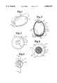
- FIG. 1illustrates a perspective view of a testicular prosthesis of the present invention
- FIG. 2illustrates a cross-sectional view along line 2--2 of FIG. 1;
- FIG. 3illustrates an end view (upper end in FIG. 2) of the testicular prosthesis showing the suture site
- FIG. 4illustrates a cross-sectional view along line 4--4 of FIG. 2;
- FIG. 5is a perspective view of a preferred injection site of the filament wrapped type as more fully described in the aforementioned co-pending application.
- FIG. 6illustrates a greatly enlarged cross-sectional view along line 5--5 of FIG. 5;
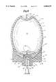
- FIG. 7illustrates an alignment fixture
- FIG. 8illustrates the method of injecting adhesive into the interior of the elastomeric shell of the prosthesis when mounting an injection site therein;
- FIG. 9illustrates the elastomeric shell of the prosthesis being rotated off vertical to form an evacuation dome
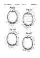
- FIG. 10illustrates the elastomeric shell of the prosthesis and self-sealing injection site subsequent to fixture removal
- FIG. 11Aillustrates complete encapsulation of the self-sealing injection site within the cylindrical bore of the elastomeric shell of the prosthesis
- FIG. 11Billustrates radiopaque encapsulation of the self-sealing injection site in a testicular prosthesis
- FIG. 11Cillustrates radiopaque encapsulation of the self-sealing injection site in a testicular prosthesis
- FIG. 12illustrates the serialization and identification area of the testicular prosthesis
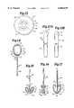
- FIG. 13Aillustrates a front view of an inverting tool used for inverting or turning a prosthesis inside out
- FIG. 13Billustrates a side view of an inverting tool
- FIG. 14illustrates the head of the inverting tool of FIGS. 12A and 12B connected to the dimple and suture tab of an empty prosthesis
- FIG. 15illustrates depressing of the empty prosthesis by the inverting tool
- FIG. 16illustrates passage of the prosthesis shell wall through its cylindrical bore for inverting the prosthesis
- FIG. 17illustrates a fully inverted elastomeric prosthesis shell
- FIG. 18illustrates the elastomeric prosthesis shell of FIG. 16 reversed for laser engraving with the inserting tool removed;
- FIG. 19illustrates a side view of a re-inverting tool for returning the prosthesis to its original condition as shown in FIG. 13;
- FIG. 20illustrates engagement of the re-inverting tool with the elastomeric shell of the prosthesis
- FIG. 21illustrates the suture tab being presented for suturing by squeezing the prosthesis
- FIG. 22illustrates the filling of the testicular prosthesis with fluid
- FIG. 23illustrates the evacuation of air and excess solution from the testicular prosthesis
- FIG. 24illustrates a butterfly needle penetrating the evacuation dome of the testicular prosthesis.
- FIG. 1illustrates a perspective view of the testicular prosthesis 10 including a shell 12 which is transfer, injection, compression or otherwise suitably molded from a silicone elastomer such as Dow Corning Q7-4840 or Q7-4735 or an equivalent material, such as NUSIL TECHNOLOGY MED-4735 OR MED 4840.
- the elastomeric shell 12is elliptical in longitudinal cross-section to replicate the shape of a testicle and is of a circular shape in transverse cross section.
- the shell 12can be produced in a number of sizes to accommodate the proper testicle size required by a patient, and can be filled as required to a preferred firmness or feel.
- the elastomeric shell wallis approximately 0.030 inches thick on the sides 14 for purposes of example and illustration only, and increasingly tapers to a thickness of 0.170 inches at one end 16 to accommodate a self-sealing injection site 18. Molding with matched cavity and core tooling is the preferred mode of fabrication due to the varying wall thickness of the shell. Dip molding may be used although it is not as precise or as fast.
- the self-sealing injection site 18is bonded into an opening 24 in the end 16 of the elastomeric shell 12 by a medical grade adhesive 20 and aligned therein prior to bonding by means of a fixture as described later in detail.
- a self-presenting suture tab 22is carried at the opposite end of shell 12 for suturing the shell to the scrotum or other convenient attachment point, if desired.
- FIG. 2illustrates a cross-section of the testicular prosthesis 10 along line 2--2 of FIG. 1. All numerals correspond to those elements previously described.
- Shell 12includes an outer surface 15 and an inner surface 26.
- the thick wall end 16 of elastomeric shell 12includes the cylindrical bore 24 into which the self-sealing injection site 18, the preferred form of which is the subject of the aforementioned co-pending patent application, is centrally aligned and bonded by a medical grade adhesive 20.
- Adhesive 20also bonds to the inner surface 26 of the shell wall 14 over an area thereof as shown in FIG. 12, as well as in the cylindrical bore 24 and to all external sides of the self-sealing injection site 18.
- An evacuation dome 25is located above the inner end of self-sealing injection site 18.
- a dimple 28 at the opposing end 30 of elastomeric shell 12serves as a shock absorptive mount connecting the relatively thin wall 14 to the suture tab 22 through which a suture may be passed.
- the profile of suture tab 22conforms generally to the elliptical profile of shell 12 so as not to exceed the device profile.
- the suture tab 22may contain a hole 23 which is preferably oval in shape. Alternately, a suture, with or without a needle, may be pre-attached.
- a serialization and identification area 64may also be included on inner surface 26 and is preferably covered by the medical grade adhesive 20, as described later in detail.
- FIG. 3is an end view of end 30 of the testicular prosthesis 10 showing the tab 22 from the top. All numerals correspond to those elements previously described.
- FIG. 4is a cross-sectional view along line 4--4 of FIG. 2. Illustrated in particular is substantially equidistant annular space 54 between self-sealing injection site 18 and cylindrical bore 24 which contains adhesive 20.
- the self-sealing injection site 18includes a center elastomeric core 32 bonded by a continuously adhesive coated strand 34 as described in FIG. 5 in more detail. All other numerals correspond to those elements previously described.
- FIG. 6is a cross-sectional view of the self-sealing injection site 18 along line 6--6 of FIG. 5.
- the injection site shown in FIG. 5is the type referred to in the aforementioned co-pending application. All numerals correspond to those elements previously described.
- the center core 32 of self-sealing injection site 18 of these FIGS. 5 and 6is a silicone elastomer which in fabrication is stretched and then tightly bound while in compression by an adhesive coated fiberglass strand 34 having a plurality of filaments 35a-35n. This procedure holds the center core 32 in compression thereby storing energy in the core and enhancing the self-sealability of the self-sealing injection site 18. This is more fully described in the aforementioned copending application.
- a medical grade flexible adhesive 37such as silicone adhesive Kunststoffedic Medical Grade Adhesive (SI 1511), adheres strands 34 to themselves and to core 32. Variations in construction of preferred injection site 18 are described in the aforementioned co-pending application.
- FIG. 7illustrates a fixture 36 used for alignment of the self-sealing injection site 18 concentrically with the cylindrical bore 24 of thick end 16 of elastomeric shell 12. All numerals correspond to those elements previously described.
- Fixture 36may be made of plastic and includes generally a number of radiused portions including an upper radiused body portion 38 and a lower radiused body portion 40.
- a cavity 42 conforming to the outer configuration of thick end 16 of elastomeric shell 12aligns centrally in the upper radiused body portion 38 for subsequent alignment with the same as shown in FIG. 8.
- Another radiused portion 44extends upwardly into the region of cavity 42 to closely align within the cylindrical bore 24 of the elastomeric shell thick end 16 as shown in FIG. 8.
- Three bores 46, 48 and 50align axially either partially or fully in the radiused portion 44, the upper radiused body portion 38 or the lower radiused portion 40 as illustrated.
- Bore 46accommodates self-sealing injection site 18 and bores 48 and 50 accommodate a fill needle 52 as illustrated in FIG. 8.
- FIG. 8demonstrates the method of injecting medical grade adhesive 20 into the interior 80 of elastomeric shell 12 to bond injection site 18 into opening 24. All numerals correspond to those elements previously described.
- Elastomeric shell 12is first aligned in the conforming shaped cavity 42 of fixture 36.
- the radiused portion 44 of fixture 36aligns centrally within the cylindrical bore 24 of elastomeric shell 12.
- the self-sealing injection site 18, which is placed in the upper bore 46 prior to alignment of the elastomeric shell 12 with the fixture 36,is also centrally aligned within the cylindrical bore 24.
- a non-coring needle 52having one or more ports 53 and having a source of thinned medical grade adhesive 20 attached thereto (not shown) is inserted through the bores 50 and 48 and through the self-sealing injection site 18.
- Adhesive 20then enters the lower region of the elastomeric shell 12 about and above the vicinity of bore 24 as illustrated such that adhesive 20 covers the lower inner region of elastomeric shell 12, the serialization and identification area 64, and the top inner surface of self-sealing injection site 18.
- Needle 52is then withdrawn from injection site 18 and fixture 36. The elastomeric shell 12 and fixture 36 are then slowly rotated (shown in FIG.
- fixture 36is withdrawn from engagement with the elastomeric shell 12 leaving self-sealing injection site 18 concentrically aligned within cylindrical bore 24 and adhered to the lower region of elastomeric shell 12 by the interceding medical grade adhesive 20 as shown in FIG. 10.
- FIG. 9illustrates the elastomeric shell 12 being rotated about an axis 58 which is at a variable angle 60 to the vertical 62.
- Angle 60generally is 35°, but can include a range of degrees in that several factors such as but not limited to elastomeric shell 12 size, adhesive viscosity, rate of rotation, angle of rotation, temperature, and adhesive setting time may require different angular settings, different rotation speeds, as well as different rates of tipping, other than described herein.
- a suitable rotatable clamping device 63slowly rotates the fixture 36 and the adhesive laden elastomeric shell 12 at a speed of 4 rpm plus or minus one rpm, for example.
- the viscous adhesive 20flows outwardly leaving the shaped evacuation dome 25 centered radially about the longitudinal axis of elastomeric shell 12 when shell 12 is tipped at an angle as now described in detail.
- the axis of rotation 58is progressively and slowly tipped over a period of about one minute from the vertical axis 62 until reaching the desired angle 60 of 35° which is the most desirable of angles which can range from 35 to 55 degrees depending on the size of elastomeric shell 12 and the other factors previously described.
- adhesive 20flows from the area over and about the upper area of self-sealing injection site 18 and along the lower portion of inner surface 26 to remove adhesive 20 from the area overlying self-sealing injection site 18 to form the evacuation dome 25.
- the elastomeric shell 12may be spun rapidly from 500 to 1,000 rpm for 10 to 20 seconds, for purpose of example, along the vertical axis to cause the adhesive 20 to flow away from the center to form evacuation dome 25.
- FIG. 10shows the elastomeric shell 12 and the self-sealing injection site 18 subsequent to removal of fixture 36. Again, all numerals correspond to those elements previously described.
- the self-sealing injection site 18is suspended concentrically from the adhesive 20 within cylindrical bore 24.
- An annular space 54 defined by the annular area between the circumferential surface of the self-sealing injection site 18 and the adjacent walls of the cylindrical bore 24 and another circular space area 56 between the plane of the outer surface of the self-sealing injection site 18, the bottom of the annular space 54 and a plane across the outer opening of the cylindrical bore 24are then back-filled by the medical grade adhesive 20 as illustrated in FIG. 11A to fully and adhesively secure and encapsulate the self-sealing injection site 18 within cylindrical bore 24 of elastomeric shell 12.
- FIG. 11Aillustrates the complete encapsulation of the self-sealing injection site 18 within cylindrical bore 24 of elastomeric shell 12. Again, all numerals correspond to those elements previously described.
- Backfilling with adhesive 20 of the cylindrical bore 24 in areas 54 and 56forms a homogenous surroundment of adhesive 20 about the self-sealing injection site 18.
- the newly applied backfill adhesivebeing of the same type, provides for bonding of the previously cured adhesive and the newly applied adhesive to form a homogenous bonding.
- Elastomeric shell 12is of a medical grade low durometer silicone elastomer, thus allowing the elastomeric shell 12 to be soft and resilient.
- the self-sealing injection site 18is also preferably constructed of a low durometer medical grade silicone elastomer which has minimal palpability and which is easily compressed.
- the silicone adhesive 20 when cured and hardenedpreferably has durometer and elongation qualities similar to the other silicone elastomeric members which it bonds together.
- the silicone adhesive 20being medical grade is biocompatable and biostable.
- a compressed self-sealing injection site 18is incorporated, other suitable valves, such as a diaphragm valve or leaf valve may be used for shell filling.
- the elastomeric shellmay also be dip molded on a mandrel.
- annular area 64for serialization and identification of the product.
- a lasercuts or engraves identification indicia and a serial number within the annular area 64.
- the laser cuts or engravingsare filled with an elastomer containing a dye such as, but not limited to, carbon black to accent the identification indicia and serialization.
- the laser engravingoccurs before the medical grade adhesive 20 is applied to the surface 26 for the adhering of the self-sealing injection site 18 within cylindrical bore 24.
- the accessing of the interior of the elastomeric shell 12 for this purposeis described with reference to FIGS. 13-20.
- adhesive 20flows along and adjacent to the thicker portion 16 and covers, fills in and mends the laser cuts in the annular area 64 to restore and maintain structural integrity, as well as sealing the accenting carbon black or other material from the interior of elastomeric shell 12.
- the serialization and identificationare viewed through the clear elastomeric shell 12 in the area of the thicker portion 16 as depicted in FIG. 12.
- serialization and identification indiciamay be silk screened or otherwise suitably adhered or applied to the annular area 64 or any other suitable portion of the inner surface 26.
- FIG. 11Billustrates the complete encapsulation of self-sealing injection site 18 and also the incorporation of a band of suitable radiopaque adhesive 20a containing for example barium sulfate (BaSo 4 ) in a range of 14% to provide a radiopaque member surrounding the self-sealing injection site 18 in the upper portion of the annular area of the cylindrical bore 24 surrounding the self-sealing injection site 18.
- Band 20ais placed in position and then adhesive 20 is backfilled into the remaining area of cylindrical bore 24 about the remaining portion of the self-sealing injection site 18 as before described and in direct adhesion with the barium sulfate laden adhesive 20a. All numerals correspond to those elements previously described.
- FIG. 11Cillustrates the complete encapsulation of a self-sealing injection site 18 incorporating an alternate band arrangement of suitable radiopaque adhesive 20b containing barium sulfate (BaSo 4 ) in a range of 14% to provide for a radiopaque member surrounding the self-sealing injection site 18.
- Adhesive 20bis backfilled in areas 54 and 56 of cylindrical bore 24 in direct contact with adhesive 20 to complete the encapsulation of self-sealing injection site 18. All elements correspond to those elements previously described.
- FIG. 12is a top view of the testicular prosthesis 10 showing the serialization and identification area 64 as visible through the thick end 16 of elastomeric shell 12 as previously mentioned. All numerals correspond to those elements previously described.
- FIGS. 13A and 13Billustrate a front view and a side view, respectively, of an inverting tool 66 having a handle 68, an essentially rounded head 70 and a groove 72 aligned across and through head 70.
- FIGS. 14-17illustrate the method of inverting elastomeric shell 12 (prior to placement of injection site 18) for exposing inner surface 26 and the laser cutting of the serialization and identification area 64 on the interior surface 26 when elastomeric shell 12 has been temporarily turned inside out, thus causing the inner surface 26 to become a temporary "outer surface". All other numerals correspond to those elements previously described.
- the inverting processstarts with the positioning of elastomeric shell 12 to place cylindrical bore 24 in the top most position as shown in FIG. 14.
- the inside surface 26is wetted with water and then drained.
- a small amount of lubricant 74such as alcohol is then placed in the elastomeric shell through the cylindrical bore 24 and allowed to drain downwardly and around and about the inner surface of the dimple 28.
- FIG. 14head 70 of inverting tool 66 is placed in intimate contact with dimple 28, and the groove 72 of the tool is brought into intimate contact with the suture tab 22.
- the alcohol or other lubricant 74facilitates turning the elastomeric shell 12 inside out.
- the upper portion of elastomeric shell 12 and the inverting tool 66are exchanged vertically such that inverting tool 66 is positioned downwardly with respect to elastomeric shell 12 as illustrated in FIG. 15.
- the inside surface 26 in the vicinity of the lubricant wetted dimple 28is then pushed through cylindrical bore 24 as illustrated in FIG. 16.
- FIG. 16illustrates the engagement and passage of the shell wall 14 through cylindrical bore 24. It is noted that the inner surface 26 at this stage is transitioning from an inner surface to an "outer surface", and the outer surface 15 is transitioning to an "inner surface", all temporarily for the placement of the indicia and the like.
- FIG. 17illustrates the fully inverted elastomeric shell 12 having at this stage been completely reversed to fully transpose interior surface 26 to an "outer surface” and ready the elastomeric shell for laser serialization and identification.
- the inverting toolis then removed and elastomeric shell 12 rinsed with deionized water and oven dried at 130° F. until dry.
- FIG. 18illustrates a method of laser cutting the indicia and serialization. All numerals correspond to those elements previously described. Elastomeric shell 12 having been turned inside out as previously described, thus positioning the former inner surface 26 to the exterior. The annular identification and indicia area 64 is fully exposed so that a laser beam 76 from a laser gun 78 may scribe identification and serialization indicia into the annular area 64. A thin coat of liquid colored silicone elastomer is then applied over the laser engraved areas using a sponge tipped or other suitable applicator. The excess silicone elastomer is removed with a swab and Freon or other suitable solvent. The inked elastomeric shell 12 is then cured at 200° F. +/-5° F. for a suitable length of time.
- FIG. 19illustrates a side view of a re-inverting tool 80 including a handle 82, a truncated cone-like tip 84 and a conical recess 86 in the tip 84.
- FIG. 20illustrates the engagement of re-inverting tool 80 with the inverted elastomeric shell 12. All numerals correspond to those elements previously described.
- the re-inverting processis quite similar to the inverting process. Surface 15, now which is presently the "inner surface”, is wetted with water and trained. A small amount of lubricant is then introduced for facilitating the re-inverting of elastomeric shell 12. Recess 86 of the re-inverting tool is brought into contact with reversed dimple 28 as shown in FIG. 20. Elastomeric shell 12 and re-inverting tool 80 are vertically reversed to allow the lubricant to flow about surface 15.
- the re-inverting toolis then pushed to extrude the dimple 28 and shell wall 14 through cylindrical bore 24 to completely re-invert the elastomeric shell 12.
- the re-inverted elastomeric shellis washed and dried and is then ready for further processing as already described above having to do with placement of the injection site and so forth.
- FIG. 21illustrates the suture tab 22 being presented by grasping and squeezing the upper portion of the testicular prosthesis 10 between a thumb 88 and a finger 90. All other numerals correspond to those elements previously described.
- This actioncauses reversal and outward distention of dimple 28 to elevate the suture tab 22 above the elliptical profile curve of elastomeric shell 12, thus presenting a suture tab 22 having unrestricted access.
- the distension of the suture tab 22provides clearance for suture needle introduction. This procedure allows suturing with reduced possibilities of puncture of elastomeric shell 12 as suture tab 22 is presented unencumbered by interfering and adjacent surfaces. Flexing of the shell presents the suture tab for easy suture needle access to reduce puncture vulnerability.
- FIGS. 22 and 23illustrate the steps for the preferred method of filling the testicular prosthesis 10 with a saline or other biologically safe fluid. All numerals correspond to those elements previously described.
- a purged syringe 92 having a non-coring butterfly needle 94is used to inject and overfill an amount of saline or other suitable solution 96 into the interior of the testicular prosthesis 10 via an infusion line 98, the non-coring butterfly needle 94 and Luer fitting 100.
- the butterfly needle 94also includes a planar handle 95 which serves as a stop device to allow penetration of the needle 94 to a predetermined depth as described later in detail.
- the non-coring butterfly needle 94is inserted through the medical grade adhesive 20, through the self-sealing injection site 18 and just beyond the evacuation dome 25 into the interior 102.
- prosthesis 10is maintained upright as shown in the Figure during filling but this is not necessary.
- the syringe plungeris slowly depressed to distend (indicated by the arrows) the testicular prosthesis 10 to about 1 to 11/2 times its empty size.
- Solution 96forcibly enters the interior 102 and causes several actions. Firstly, air 104 in the elastomeric shell 12 is compressed by the incoming solution 96. Secondly, the wall 14 of the elastomeric wall is expanded outwardly due to the action of the incoming solution 96 and the compression of the air 104.
- FIG. 23illustrates the air evacuation portion of the filling method. All numerals correspond to those elements previously described.
- the filled testicular prosthesis 10is inverted causing the contained air 104 to migrate from near the suture end to the end nearest the evacuation dome 25, which is adjacent to the now upwardly positioned self-sealing injection site 18.
- the testicular prosthesis 10is gently shaken until all internal air 104 is one large bubble in the upper end. Once this is accomplished, the plunger 106 of syringe 92 is progressively withdrawn.
- the stored energy in the testicular prosthesis 10causes the compressed air 104 to exit through the port(s) of the butterfly needle 94 as the plunger 106 is manually released and the air travels to the top of syringe 92.
- Walls 14which were outwardly and forcibly expanded during the first portion of the filling process, now relax inwardly (indicated by arrows) to assist in expelling of any remaining air 104.
- the level of solution 96approaches evacuation dome 25.
- Air 104is concentrated at this point in the procedure substantially to the area of the evacuation dome 25 where the air and any desired amount of excess solution 96 is subsequently drawn off through butterfly needle 94.
- butterfly needle 94is withdrawn and the self-sealing injection site 18 seals the puncture caused by the butterfly needle 94, thus sealing the interior 102 of the testicular prosthesis 10.
- the self-sealing injection site 18can be punctured repeatedly permitting adjustment of the fluid volume if desired.
- FIG. 24shows the butterfly needle 94 penetrating the evacuation dome 25. All numerals correspond to those elements previously described.
- Handle 95acts as a stop and is located at a predetermined point along needle 94 allowing the orifice(s) 108 to be precisely located at the same level and coinciding with the upper most portion of the evacuation dome 25.
- the preferred placement of the orifice(s) 108is as illustrated, where the orifice(s) 108 straddle the evacuation dome area 25a, which is the upper most central area of the evacuation dome 25 when the testicular prosthesis 10 is positioned for removal of air 104 and some of solution 96.
- the filling methodhas been described as being accomplished preoperatively i.e., immediately before implantation or at the time of manufacture as a prefill. However, it may be readily accomplished postoperatively i.e., after implantation as well.
Landscapes
- Health & Medical Sciences (AREA)
- Cardiology (AREA)
- Oral & Maxillofacial Surgery (AREA)
- Transplantation (AREA)
- Engineering & Computer Science (AREA)
- Biomedical Technology (AREA)
- Heart & Thoracic Surgery (AREA)
- Vascular Medicine (AREA)
- Life Sciences & Earth Sciences (AREA)
- Animal Behavior & Ethology (AREA)
- General Health & Medical Sciences (AREA)
- Public Health (AREA)
- Veterinary Medicine (AREA)
- Prostheses (AREA)
- Compounds Of Unknown Constitution (AREA)
Abstract
Description
Claims (23)
Priority Applications (15)
| Application Number | Priority Date | Filing Date | Title |
|---|---|---|---|
| US08/207,023US6060639A (en) | 1994-03-04 | 1994-03-04 | Testicular prosthesis and method of manufacturing and filling |
| ES95912734TES2158940T3 (en) | 1994-03-04 | 1995-03-03 | TESTICULAR PROTESIS AND MANUFACTURE AND FILLING PROCEDURE. |
| PCT/US1995/002741WO1995023565A2 (en) | 1994-03-04 | 1995-03-03 | Testicular prosthesis and method of manufacturing and filling |
| DE69521304TDE69521304T2 (en) | 1994-03-04 | 1995-03-03 | Testicular prosthesis and method of manufacture and filling |
| DK95912734TDK0748192T3 (en) | 1994-03-04 | 1995-03-03 | Testicular prosthesis and method for its preparation and filling |
| EP95912734AEP0748192B1 (en) | 1994-03-04 | 1995-03-03 | Testicular prosthesis and method of manufacturing and filling |
| AU19793/95AAU701672B2 (en) | 1994-03-04 | 1995-03-03 | Testicular prosthesis and method of manufacturing and filling |
| AT95912734TATE201976T1 (en) | 1994-03-04 | 1995-03-03 | TESTIC PROSTHESIS AND METHOD FOR MANUFACTURING AND FILLING |
| PT95912734TPT748192E (en) | 1994-03-04 | 1995-03-03 | TESTICULAR PROTESIS AND PROCESS FOR THEIR MANUFACTURE AND FILLING |
| CA002186952ACA2186952C (en) | 1994-03-04 | 1995-03-03 | Testicular prosthesis and method of manufacturing and filling |
| US08/452,405US5632777A (en) | 1994-03-04 | 1995-05-26 | Method of inflating a prosthesis |
| US08/452,007US5558829A (en) | 1994-03-04 | 1995-05-26 | Method for providing a prosthesis with an injection port |
| US08/452,006US5653757A (en) | 1994-03-04 | 1995-07-10 | Method of using a testicular prosthesis |
| AU52106/98AAU706502B2 (en) | 1994-03-04 | 1998-01-16 | Testicular prosthesis and method of manufacturing and filling |
| GR20010401375TGR3036515T3 (en) | 1994-03-04 | 2001-09-04 | Testicular prosthesis and method of manufacturing and filling |
Applications Claiming Priority (1)
| Application Number | Priority Date | Filing Date | Title |
|---|---|---|---|
| US08/207,023US6060639A (en) | 1994-03-04 | 1994-03-04 | Testicular prosthesis and method of manufacturing and filling |
Related Child Applications (3)
| Application Number | Title | Priority Date | Filing Date |
|---|---|---|---|
| US08/452,405DivisionUS5632777A (en) | 1994-03-04 | 1995-05-26 | Method of inflating a prosthesis |
| US08/452,007DivisionUS5558829A (en) | 1994-03-04 | 1995-05-26 | Method for providing a prosthesis with an injection port |
| US08/452,006DivisionUS5653757A (en) | 1994-03-04 | 1995-07-10 | Method of using a testicular prosthesis |
Publications (1)
| Publication Number | Publication Date |
|---|---|
| US6060639Atrue US6060639A (en) | 2000-05-09 |
Family
ID=22768896
Family Applications (4)
| Application Number | Title | Priority Date | Filing Date |
|---|---|---|---|
| US08/207,023Expired - LifetimeUS6060639A (en) | 1994-03-04 | 1994-03-04 | Testicular prosthesis and method of manufacturing and filling |
| US08/452,405Expired - LifetimeUS5632777A (en) | 1994-03-04 | 1995-05-26 | Method of inflating a prosthesis |
| US08/452,007Expired - LifetimeUS5558829A (en) | 1994-03-04 | 1995-05-26 | Method for providing a prosthesis with an injection port |
| US08/452,006Expired - LifetimeUS5653757A (en) | 1994-03-04 | 1995-07-10 | Method of using a testicular prosthesis |
Family Applications After (3)
| Application Number | Title | Priority Date | Filing Date |
|---|---|---|---|
| US08/452,405Expired - LifetimeUS5632777A (en) | 1994-03-04 | 1995-05-26 | Method of inflating a prosthesis |
| US08/452,007Expired - LifetimeUS5558829A (en) | 1994-03-04 | 1995-05-26 | Method for providing a prosthesis with an injection port |
| US08/452,006Expired - LifetimeUS5653757A (en) | 1994-03-04 | 1995-07-10 | Method of using a testicular prosthesis |
Country Status (11)
| Country | Link |
|---|---|
| US (4) | US6060639A (en) |
| EP (1) | EP0748192B1 (en) |
| AT (1) | ATE201976T1 (en) |
| AU (1) | AU701672B2 (en) |
| CA (1) | CA2186952C (en) |
| DE (1) | DE69521304T2 (en) |
| DK (1) | DK0748192T3 (en) |
| ES (1) | ES2158940T3 (en) |
| GR (1) | GR3036515T3 (en) |
| PT (1) | PT748192E (en) |
| WO (1) | WO1995023565A2 (en) |
Cited By (33)
| Publication number | Priority date | Publication date | Assignee | Title |
|---|---|---|---|---|
| US20020055757A1 (en)* | 2000-11-03 | 2002-05-09 | Torre Roger De La | Method and device for use in minimally invasive placement of intragastric devices |
| US6613087B1 (en)* | 1996-12-31 | 2003-09-02 | St. Jude Medical, Inc. | Indicia for prosthetic device |
| US6743254B2 (en) | 2002-02-01 | 2004-06-01 | Mentor Corporation | Tissue expander with protection against accidental puncture |
| US20060058890A1 (en)* | 2004-09-16 | 2006-03-16 | Lesh Michael D | Methods for soft tissue augmentation |
| US20060058891A1 (en)* | 2004-09-16 | 2006-03-16 | Lesh Michael D | Transformable tissue bulking device |
| US20060058892A1 (en)* | 2004-09-16 | 2006-03-16 | Lesh Michael D | Valved tissue augmentation implant |
| US20060058735A1 (en)* | 2004-09-16 | 2006-03-16 | Lesh Michael D | Systems and devices for soft tissue augmentation |
| FR2877582A1 (en)* | 2004-11-05 | 2006-05-12 | Cie Euro Etude Rech Paroscopie | IMPLANTABLE MEDICAL SITE WITH MULTI-LAYER PUNCTURE AREA |
| US20060161253A1 (en)* | 2004-09-16 | 2006-07-20 | Michael Lesh | Tissue augmentation device |
| US20070142700A1 (en)* | 2005-12-19 | 2007-06-21 | Fogarty Terence M | Pump with one-touch release |
| CN100423793C (en)* | 2006-10-26 | 2008-10-08 | 上海交通大学医学院附属新华医院 | Preparation method of slow-release testicular prosthesis |
| US20080275569A1 (en)* | 2004-09-16 | 2008-11-06 | Evera Medical, Inc | Tissue Augmentation Device |
| US20080305279A1 (en)* | 2006-10-31 | 2008-12-11 | Duncan Young | Method of marking a surgical article |
| US20090198331A1 (en)* | 2008-02-01 | 2009-08-06 | Kesten Randy J | Implantable prosthesis with open cell flow regulation |
| CN101940505A (en)* | 2010-10-11 | 2011-01-12 | 中国人民解放军第三军医大学第三附属医院 | Testicle prosthesis |
| US20110118540A1 (en)* | 2009-11-16 | 2011-05-19 | Coloplast A/S | Penile prosthetic with anti-autoinflation mechanism |
| US20110190576A1 (en)* | 2010-02-04 | 2011-08-04 | Coloplast A/S | Inflatable penile implant |
| US20110190577A1 (en)* | 2010-02-03 | 2011-08-04 | Coloplast A/S | Inflatable penile implant |
| CN102188295A (en)* | 2010-03-05 | 2011-09-21 | 上海交通大学医学院附属上海儿童医学中心 | Expansion type testicular prosthesis |
| US8257246B1 (en) | 2011-04-19 | 2012-09-04 | Coloplast A/S | Penile prosthetic system and pump having inlet valve with high velocity closure mechanism |
| US20120310346A1 (en)* | 2010-05-12 | 2012-12-06 | Uwe Steinhardt | Test device for having thermal dummy for ossicular prosthesis with memory effect |
| US9333070B2 (en) | 2008-02-01 | 2016-05-10 | Evera Medical, Inc. | Breast implant with internal flow dampening |
| US9351824B2 (en) | 2012-11-14 | 2016-05-31 | ImplantADJUST, LLC | Adjustable implant with self-sealing elastomeric membrane and methods of fabrication thereof |
| US9554937B2 (en) | 2014-06-16 | 2017-01-31 | Coloplast A/S | Penile prosthetic pump having an inlet valve with a lockout flange |
| US9649217B2 (en) | 2014-07-08 | 2017-05-16 | Coloplast A/S | Implantable penile prosthetic lockout valve assembly |
| US9987136B2 (en) | 2016-09-09 | 2018-06-05 | Coloplast A/S | Penile prosthetic pump with an inflation assembly including a rotary valve |
| US20180193057A1 (en)* | 2012-08-10 | 2018-07-12 | Attenuex Technologies, Inc. | Methods and systems for performing a medical procedure |
| KR20200031342A (en)* | 2018-09-14 | 2020-03-24 | 부산대학교 산학협력단 | Artificial testis and method for manufacturing same |
| US10706744B2 (en) | 2018-03-16 | 2020-07-07 | Coloplast A/S | Penile prosthesis demonstration tool |
| US10820984B2 (en) | 2012-11-14 | 2020-11-03 | ImplantADJUST, LLC | Implant with elastomeric membrane and methods of fabrication thereof |
| US11197981B2 (en) | 2019-02-07 | 2021-12-14 | Solace Therapeutics, Inc. | Pressure attenuation device |
| US11580884B2 (en) | 2019-05-10 | 2023-02-14 | Coloplast A/S | Anatomical teaching model |
| US12303379B2 (en) | 2018-09-10 | 2025-05-20 | Mentor Worldwide, Llc | Implant with elastomeric membrane and methods of fabrication thereof |
Families Citing this family (35)
| Publication number | Priority date | Publication date | Assignee | Title |
|---|---|---|---|---|
| US5895424A (en)* | 1996-11-12 | 1999-04-20 | Mentor Corporation | Prosthesis having an alignment indicator and method of using same |
| US6017407A (en)* | 1997-10-22 | 2000-01-25 | Yates; Paul M. | Method of manufacturing a cushion article |
| US6066856A (en)* | 1998-05-18 | 2000-05-23 | Children's Medical Center Corporation | Radiation protective device |
| FR2781142B1 (en) | 1998-07-16 | 2000-10-06 | Perouse Implant Lab | RECONSTRUCTION IMPLANT |
| US6039091A (en)* | 1998-08-03 | 2000-03-21 | Mentor Corporation | Filling device for use in manufacturing of gel filled prostheses |
| US6143228A (en)* | 1998-11-12 | 2000-11-07 | Andrew Corporation | Method of making a resilient outer covering |
| US6436143B1 (en) | 1999-02-22 | 2002-08-20 | Anthony C. Ross | Method and apparatus for treating intervertebral disks |
| US6283998B1 (en)* | 1999-05-13 | 2001-09-04 | Board Of Trustees Of The University Of Arkansas | Alloplastic vertebral disk replacement |
| US6315796B1 (en)* | 1999-05-13 | 2001-11-13 | Board Of Trustees Of The University Of Arkansas | Flexible seamless memory tissue expanding implant |
| US6520989B1 (en) | 2000-01-18 | 2003-02-18 | Board Of Trustees Of The University Of Arkansas | Extreme volume flexible integrity prosthesis |
| WO2001082828A2 (en)* | 2000-04-28 | 2001-11-08 | Anthony Atala | Tissue engineered testicular prosthesis and use thereof |
| US6588432B1 (en)* | 2001-02-15 | 2003-07-08 | Pmt Corporation | Tissue expander magnetic injection port |
| WO2002089699A2 (en)* | 2001-05-03 | 2002-11-14 | Glaukos Corporation | Medical device and methods of use for glaucoma treatment |
| US7160325B2 (en)* | 2001-05-15 | 2007-01-09 | Ams Research Corporation | Implantable medical balloon and valve |
| US7156877B2 (en)* | 2001-06-29 | 2007-01-02 | The Regents Of The University Of California | Biodegradable/bioactive nucleus pulposus implant and method for treating degenerated intervertebral discs |
| EP1438030A2 (en)* | 2001-09-28 | 2004-07-21 | McNEIL-PPC, INC. | Modified release dosage forms |
| US7025754B2 (en)* | 2002-07-01 | 2006-04-11 | Ventaira Pharmaceuticals, Inc. | Drug containment system |
| US8029482B2 (en) | 2005-03-04 | 2011-10-04 | C. R. Bard, Inc. | Systems and methods for radiographically identifying an access port |
| US7947022B2 (en) | 2005-03-04 | 2011-05-24 | C. R. Bard, Inc. | Access port identification systems and methods |
| JP5484674B2 (en) | 2005-03-04 | 2014-05-07 | シー・アール・バード・インコーポレーテッド | Access port and identification method |
| US9474888B2 (en) | 2005-03-04 | 2016-10-25 | C. R. Bard, Inc. | Implantable access port including a sandwiched radiopaque insert |
| EP3884989B1 (en) | 2005-04-27 | 2022-07-13 | C. R. Bard, Inc. | Vascular access port |
| US10307581B2 (en) | 2005-04-27 | 2019-06-04 | C. R. Bard, Inc. | Reinforced septum for an implantable medical device |
| EP1874393B1 (en) | 2005-04-27 | 2017-09-06 | C.R.Bard, Inc. | Infusion apparatuses |
| US20070077544A1 (en)* | 2005-06-16 | 2007-04-05 | Gottfried Lemperle | Life-like anatomic feature for testing injection of soft tissue fillers |
| US20070067041A1 (en)* | 2005-09-16 | 2007-03-22 | Kotoske Thomas G | Inflatable facial implant and associated method |
| US20080046078A1 (en)* | 2006-08-15 | 2008-02-21 | Singer Matthew A | Silicone based ocular prosthesis, and method for making same |
| US9642986B2 (en) | 2006-11-08 | 2017-05-09 | C. R. Bard, Inc. | Resource information key for an insertable medical device |
| US9265912B2 (en) | 2006-11-08 | 2016-02-23 | C. R. Bard, Inc. | Indicia informative of characteristics of insertable medical devices |
| WO2008142174A1 (en)* | 2007-05-24 | 2008-11-27 | Invenciones Medico Sanitarias, S.L. | Improved testicular prosthesis |
| US9579496B2 (en) | 2007-11-07 | 2017-02-28 | C. R. Bard, Inc. | Radiopaque and septum-based indicators for a multi-lumen implantable port |
| US11890443B2 (en) | 2008-11-13 | 2024-02-06 | C. R. Bard, Inc. | Implantable medical devices including septum-based indicators |
| US8932271B2 (en) | 2008-11-13 | 2015-01-13 | C. R. Bard, Inc. | Implantable medical devices including septum-based indicators |
| ES2695907T3 (en) | 2009-11-17 | 2019-01-11 | Bard Inc C R | Overmolded access port that includes anchoring and identification features |
| US12036123B2 (en)* | 2021-02-10 | 2024-07-16 | Menova International, Inc. | Testicular implant device and method |
Citations (48)
| Publication number | Priority date | Publication date | Assignee | Title |
|---|---|---|---|---|
| US3600718A (en)* | 1969-12-29 | 1971-08-24 | Dow Corning | Inflatable prosthesis |
| US3839821A (en)* | 1972-09-20 | 1974-10-08 | A Forsman | Decorative badge with movable eyes and mouth |
| US3839743A (en)* | 1972-04-21 | 1974-10-08 | A Schwarcz | Method for maintaining the normal integrity of blood |
| US3883902A (en)* | 1972-08-16 | 1975-05-20 | Medical Eng Corp | Variable volume prosthetic assembly |
| US3902198A (en)* | 1974-05-20 | 1975-09-02 | Gore & Ass | Method of replacing a body part with expanded porous polytetrafluoroethylene |
| US3919724A (en)* | 1974-06-07 | 1975-11-18 | Medical Eng Corp | Implantable prosthesis having a self-sealing valve |
| US3934274A (en)* | 1974-10-29 | 1976-01-27 | Hartley Jr John H | Deflatable mammary augmentation prosthesis |
| US4190040A (en)* | 1978-07-03 | 1980-02-26 | American Hospital Supply Corporation | Resealable puncture housing for surgical implantation |
| US4201202A (en)* | 1978-09-25 | 1980-05-06 | Medical Engineering Corp. | Penile implant |
| US4216774A (en)* | 1978-11-13 | 1980-08-12 | Alegra Products, Inc. | Medical pad |
| US4217889A (en)* | 1976-09-15 | 1980-08-19 | Heyer-Schulte Corporation | Flap development device and method of progressively increasing skin area |
| US4253201A (en)* | 1979-05-24 | 1981-03-03 | Ross David A | Prosthesis with self-sealing valve |
| US4263682A (en)* | 1978-09-01 | 1981-04-28 | Dow Corning Corporation | Self-sealing valve and fluid fillable article including such a valve |
| US4413359A (en)* | 1981-03-04 | 1983-11-08 | Koken Co., Ltd. | Impermeable laminate membrane |
| US4428364A (en)* | 1979-04-11 | 1984-01-31 | Dow Corning Corporation | Self-sealing injection button and method of making same |
| US4520821A (en)* | 1982-04-30 | 1985-06-04 | The Regents Of The University Of California | Growing of long-term biological tissue correction structures in vivo |
| US4523584A (en)* | 1983-03-04 | 1985-06-18 | Medical Engineering Corporation | Penile erectile system |
| US4566466A (en)* | 1984-04-16 | 1986-01-28 | Ripple Dale B | Surgical instrument |
| EP0177288A2 (en)* | 1984-10-03 | 1986-04-09 | Baylor College of Medicine | Labeled breast prosthesis and methods for detecting and predicting rupture of the prosthesis |
| EP0196821A2 (en)* | 1985-03-25 | 1986-10-08 | PMT Inc | Tissue expander system |
| US4619245A (en)* | 1983-08-11 | 1986-10-28 | Habley Medical Technology Corporation | Mechanical prosthetic sphincter |
| US4662357A (en)* | 1986-01-21 | 1987-05-05 | Dow Corning Corporation | Inflatable surgical implant with variable inflation position |
| US4671255A (en)* | 1985-10-16 | 1987-06-09 | Mcghan Medical Corporation | Tissue expander with self-contained injection reservoir and reinforcing insert |
| US4726404A (en)* | 1986-12-15 | 1988-02-23 | Habley Medical Technology Corporation | Combination container and air removal fixture for simplified filling of an implantable hydraulic device |
| US4738657A (en)* | 1985-09-30 | 1988-04-19 | Mcghan Medical Corporation | Self-sealing injection reservoir |
| US4773908A (en)* | 1986-12-18 | 1988-09-27 | Hilton Becker | Filling tube and seal construction for inflatable implant |
| US4773393A (en)* | 1986-07-03 | 1988-09-27 | C. R. Bard, Inc. | Hypodermically implantable genitourinary prosthesis |
| US4798584A (en)* | 1985-09-30 | 1989-01-17 | Mcghan Medical Corporation | Self-sealing injection reservoir |
| US4802479A (en)* | 1986-10-31 | 1989-02-07 | C. R. Bard, Inc. | Hand-held instrument for implanting, dispensing, and inflating an inflatable membrane |
| US4834720A (en)* | 1987-12-24 | 1989-05-30 | Becton, Dickinson And Company | Implantable port septum |
| US4840615A (en)* | 1985-09-30 | 1989-06-20 | Mcghan Medical Corporation | Self-sealing injection reservoir |
| US4857053A (en)* | 1988-08-29 | 1989-08-15 | Dalton Michael J | Matrix septum |
| US4863470A (en)* | 1985-03-19 | 1989-09-05 | Medical Engineering Corporation | Identification marker for a breast prosthesis |
| WO1990000888A1 (en)* | 1988-07-28 | 1990-02-08 | The Cooper Companies, Inc. | Implants with a cover which resists formation of firm spherical encapsulation |
| US4955906A (en)* | 1989-01-12 | 1990-09-11 | Coggins Peter R | Mammary prosthesis injector |
| US4955907A (en)* | 1987-12-22 | 1990-09-11 | Ledergerber Walter J | Implantable prosthetic device |
| US4969899A (en)* | 1989-03-08 | 1990-11-13 | Cox-Uphoff International | Inflatable implant |
| US4992312A (en)* | 1989-03-13 | 1991-02-12 | Dow Corning Wright Corporation | Methods of forming permeation-resistant, silicone elastomer-containing composite laminates and devices produced thereby |
| US5066303A (en)* | 1989-08-07 | 1991-11-19 | Medical Engineering Corporation | Self-sealing tissue expander and method |
| US5085890A (en)* | 1988-05-06 | 1992-02-04 | Viskase Corporation | Method for preparing indicia-containing article |
| US5133753A (en)* | 1989-08-07 | 1992-07-28 | Medical Engineering Corporation | Method for expanding a self-sealing tissue prosthesis |
| US5137529A (en)* | 1990-02-20 | 1992-08-11 | Pudenz-Schulte Medical Research Corporation | Injection port |
| US5139841A (en)* | 1991-03-27 | 1992-08-18 | James River Corporation Of Virginia | Superabsorbent towel with scrim reinforcement |
| US5141508A (en)* | 1991-01-14 | 1992-08-25 | Medical Engineering Corporation | Tissue expander |
| EP0422302B1 (en)* | 1989-10-13 | 1993-09-15 | Guy-Henri Muller | Implantable prosthesis |
| US5354275A (en)* | 1993-09-13 | 1994-10-11 | Minnesota Mining And Manufacturing Company | Injection or sampling site |
| US5403293A (en)* | 1994-01-03 | 1995-04-04 | Abbott Laboratories | Molded partial pre-slit reseal |
| US5725507A (en)* | 1994-03-04 | 1998-03-10 | Mentor Corporation | Self-sealing injection sites and plugs |
- 1994
- 1994-03-04USUS08/207,023patent/US6060639A/ennot_activeExpired - Lifetime
- 1995
- 1995-03-03AUAU19793/95Apatent/AU701672B2/ennot_activeCeased
- 1995-03-03EPEP95912734Apatent/EP0748192B1/ennot_activeExpired - Lifetime
- 1995-03-03WOPCT/US1995/002741patent/WO1995023565A2/enactiveIP Right Grant
- 1995-03-03CACA002186952Apatent/CA2186952C/ennot_activeExpired - Fee Related
- 1995-03-03ATAT95912734Tpatent/ATE201976T1/ennot_activeIP Right Cessation
- 1995-03-03ESES95912734Tpatent/ES2158940T3/ennot_activeExpired - Lifetime
- 1995-03-03PTPT95912734Tpatent/PT748192E/enunknown
- 1995-03-03DKDK95912734Tpatent/DK0748192T3/enactive
- 1995-03-03DEDE69521304Tpatent/DE69521304T2/ennot_activeExpired - Lifetime
- 1995-05-26USUS08/452,405patent/US5632777A/ennot_activeExpired - Lifetime
- 1995-05-26USUS08/452,007patent/US5558829A/ennot_activeExpired - Lifetime
- 1995-07-10USUS08/452,006patent/US5653757A/ennot_activeExpired - Lifetime
- 2001
- 2001-09-04GRGR20010401375Tpatent/GR3036515T3/ennot_activeIP Right Cessation
Patent Citations (49)
| Publication number | Priority date | Publication date | Assignee | Title |
|---|---|---|---|---|
| US3600718A (en)* | 1969-12-29 | 1971-08-24 | Dow Corning | Inflatable prosthesis |
| US3839743A (en)* | 1972-04-21 | 1974-10-08 | A Schwarcz | Method for maintaining the normal integrity of blood |
| US3883902A (en)* | 1972-08-16 | 1975-05-20 | Medical Eng Corp | Variable volume prosthetic assembly |
| US3839821A (en)* | 1972-09-20 | 1974-10-08 | A Forsman | Decorative badge with movable eyes and mouth |
| US3902198A (en)* | 1974-05-20 | 1975-09-02 | Gore & Ass | Method of replacing a body part with expanded porous polytetrafluoroethylene |
| US3919724A (en)* | 1974-06-07 | 1975-11-18 | Medical Eng Corp | Implantable prosthesis having a self-sealing valve |
| US3934274A (en)* | 1974-10-29 | 1976-01-27 | Hartley Jr John H | Deflatable mammary augmentation prosthesis |
| US4217889A (en)* | 1976-09-15 | 1980-08-19 | Heyer-Schulte Corporation | Flap development device and method of progressively increasing skin area |
| US4190040A (en)* | 1978-07-03 | 1980-02-26 | American Hospital Supply Corporation | Resealable puncture housing for surgical implantation |
| US4263682A (en)* | 1978-09-01 | 1981-04-28 | Dow Corning Corporation | Self-sealing valve and fluid fillable article including such a valve |
| US4201202A (en)* | 1978-09-25 | 1980-05-06 | Medical Engineering Corp. | Penile implant |
| US4216774A (en)* | 1978-11-13 | 1980-08-12 | Alegra Products, Inc. | Medical pad |
| US4428364A (en)* | 1979-04-11 | 1984-01-31 | Dow Corning Corporation | Self-sealing injection button and method of making same |
| US4253201A (en)* | 1979-05-24 | 1981-03-03 | Ross David A | Prosthesis with self-sealing valve |
| US4413359A (en)* | 1981-03-04 | 1983-11-08 | Koken Co., Ltd. | Impermeable laminate membrane |
| US4520821A (en)* | 1982-04-30 | 1985-06-04 | The Regents Of The University Of California | Growing of long-term biological tissue correction structures in vivo |
| US4523584A (en)* | 1983-03-04 | 1985-06-18 | Medical Engineering Corporation | Penile erectile system |
| US4619245A (en)* | 1983-08-11 | 1986-10-28 | Habley Medical Technology Corporation | Mechanical prosthetic sphincter |
| US4566466A (en)* | 1984-04-16 | 1986-01-28 | Ripple Dale B | Surgical instrument |
| EP0177288A2 (en)* | 1984-10-03 | 1986-04-09 | Baylor College of Medicine | Labeled breast prosthesis and methods for detecting and predicting rupture of the prosthesis |
| US4863470A (en)* | 1985-03-19 | 1989-09-05 | Medical Engineering Corporation | Identification marker for a breast prosthesis |
| US4685447A (en)* | 1985-03-25 | 1987-08-11 | Pmt Corporation | Tissue expander system |
| EP0196821A2 (en)* | 1985-03-25 | 1986-10-08 | PMT Inc | Tissue expander system |
| US4738657A (en)* | 1985-09-30 | 1988-04-19 | Mcghan Medical Corporation | Self-sealing injection reservoir |
| US4840615A (en)* | 1985-09-30 | 1989-06-20 | Mcghan Medical Corporation | Self-sealing injection reservoir |
| US4798584A (en)* | 1985-09-30 | 1989-01-17 | Mcghan Medical Corporation | Self-sealing injection reservoir |
| US4671255A (en)* | 1985-10-16 | 1987-06-09 | Mcghan Medical Corporation | Tissue expander with self-contained injection reservoir and reinforcing insert |
| US4662357A (en)* | 1986-01-21 | 1987-05-05 | Dow Corning Corporation | Inflatable surgical implant with variable inflation position |
| US4773393A (en)* | 1986-07-03 | 1988-09-27 | C. R. Bard, Inc. | Hypodermically implantable genitourinary prosthesis |
| US4802479A (en)* | 1986-10-31 | 1989-02-07 | C. R. Bard, Inc. | Hand-held instrument for implanting, dispensing, and inflating an inflatable membrane |
| US4726404A (en)* | 1986-12-15 | 1988-02-23 | Habley Medical Technology Corporation | Combination container and air removal fixture for simplified filling of an implantable hydraulic device |
| US4773908A (en)* | 1986-12-18 | 1988-09-27 | Hilton Becker | Filling tube and seal construction for inflatable implant |
| US4955907A (en)* | 1987-12-22 | 1990-09-11 | Ledergerber Walter J | Implantable prosthetic device |
| US4834720A (en)* | 1987-12-24 | 1989-05-30 | Becton, Dickinson And Company | Implantable port septum |
| US5085890A (en)* | 1988-05-06 | 1992-02-04 | Viskase Corporation | Method for preparing indicia-containing article |
| WO1990000888A1 (en)* | 1988-07-28 | 1990-02-08 | The Cooper Companies, Inc. | Implants with a cover which resists formation of firm spherical encapsulation |
| US4857053A (en)* | 1988-08-29 | 1989-08-15 | Dalton Michael J | Matrix septum |
| US4955906A (en)* | 1989-01-12 | 1990-09-11 | Coggins Peter R | Mammary prosthesis injector |
| US4969899A (en)* | 1989-03-08 | 1990-11-13 | Cox-Uphoff International | Inflatable implant |
| US4992312A (en)* | 1989-03-13 | 1991-02-12 | Dow Corning Wright Corporation | Methods of forming permeation-resistant, silicone elastomer-containing composite laminates and devices produced thereby |
| US5066303A (en)* | 1989-08-07 | 1991-11-19 | Medical Engineering Corporation | Self-sealing tissue expander and method |
| US5133753A (en)* | 1989-08-07 | 1992-07-28 | Medical Engineering Corporation | Method for expanding a self-sealing tissue prosthesis |
| EP0422302B1 (en)* | 1989-10-13 | 1993-09-15 | Guy-Henri Muller | Implantable prosthesis |
| US5137529A (en)* | 1990-02-20 | 1992-08-11 | Pudenz-Schulte Medical Research Corporation | Injection port |
| US5141508A (en)* | 1991-01-14 | 1992-08-25 | Medical Engineering Corporation | Tissue expander |
| US5139841A (en)* | 1991-03-27 | 1992-08-18 | James River Corporation Of Virginia | Superabsorbent towel with scrim reinforcement |
| US5354275A (en)* | 1993-09-13 | 1994-10-11 | Minnesota Mining And Manufacturing Company | Injection or sampling site |
| US5403293A (en)* | 1994-01-03 | 1995-04-04 | Abbott Laboratories | Molded partial pre-slit reseal |
| US5725507A (en)* | 1994-03-04 | 1998-03-10 | Mentor Corporation | Self-sealing injection sites and plugs |
Non-Patent Citations (22)
| Title |
|---|
| Bulletin from Dow Corning Corporation Medical Products titled Silastic Other Implants ( Sterile, Testicular Implant II, Lattimer Design .* |
| Bulletin from Dow Corning Corporation Medical Products titled Silastic® Other Implants (Sterile, Testicular Implant II, Lattimer Design. |
| Bulletin from Mentor Corporation titled Look at the Difference , dated Jun. 1984.* |
| Bulletin from Mentor Corporation titled Look at the Difference, dated Jun. 1984. |
| Bulletin from Mentor Corporation titled Saline Filled Mammary Prostheses , dated Feb. 1989.* |
| Bulletin from Mentor Corporation titled Saline-Filled Mammary Prostheses, dated Feb. 1989. |
| Bulletin from Poly Implant Prosthesis.* |
| Bulletin from Surgitek titled Testicular Implants .* |
| Bulletin from Surgitek titled Testicular Implants. |
| Dow Corning Bulletin dated Oct. 1962, p. 15, article titled Weighted testicular prosthesis.* |
| Dow Corning Bulletin dated Oct. 1963, p. 15, article titled Testicular Prosthesis: materials, methods, and results.* |
| Intracapsular Testicular Prosthesis, by Daniel C. Merrill, M.D. Urology , Jan. 1991, vol. XXXVII, No. 1, pp. 78.* |
| Intracapsular Testicular Prosthesis, by Daniel C. Merrill, M.D. Urology, Jan. 1991, vol. XXXVII, No. 1, pp. 78. |
| Saline Filled Mammary Prostheses, Mentor Corporation, Jul., 1986.* |
| Saline-Filled Mammary Prostheses, Mentor Corporation, Jul., 1986. |
| Siltex Saline Filled Mammary Prosthesis, Mentor H/S, Jan., 1994.* |
| Siltex Saline-Filled Mammary Prosthesis, Mentor H/S, Jan., 1994. |
| Testicular Prostheses, by Michael Beer, M.D., and Robert Kay, M.D., Genitourinary Prostheses, Urologic Clinics of North America , vol. 16, No. 1, Feb. 1988, pp. 133 139 and 539A.* |
| Testicular Prostheses, by Michael Beer, M.D., and Robert Kay, M.D., Genitourinary Prostheses, Urologic Clinics of North America, vol. 16, No. 1, Feb. 1988, pp. 133-139 and 539A. |
| Testicular Prosthesis, RME, Seeing is Believing, Mentor Urology, Sep., 1987.* |
| The why and how of synthetic replacement testicles, by Joseph Ortenberg, MD, and Robert G. Kupper MD, Contemporary Urology , Oct. 1991, pp. 23 26.* |
| The why and how of synthetic replacement testicles, by Joseph Ortenberg, MD, and Robert G. Kupper MD, Contemporary Urology, Oct. 1991, pp. 23-26. |
Cited By (52)
| Publication number | Priority date | Publication date | Assignee | Title |
|---|---|---|---|---|
| US6613087B1 (en)* | 1996-12-31 | 2003-09-02 | St. Jude Medical, Inc. | Indicia for prosthetic device |
| US7033373B2 (en)* | 2000-11-03 | 2006-04-25 | Satiety, Inc. | Method and device for use in minimally invasive placement of space-occupying intragastric devices |
| US20020055757A1 (en)* | 2000-11-03 | 2002-05-09 | Torre Roger De La | Method and device for use in minimally invasive placement of intragastric devices |
| US6743254B2 (en) | 2002-02-01 | 2004-06-01 | Mentor Corporation | Tissue expander with protection against accidental puncture |
| US7998202B2 (en) | 2004-09-16 | 2011-08-16 | Evera Medical, Inc. | Tissue implant having a biased layer and compliance that simulates tissue |
| US20080275569A1 (en)* | 2004-09-16 | 2008-11-06 | Evera Medical, Inc | Tissue Augmentation Device |
| US20060058735A1 (en)* | 2004-09-16 | 2006-03-16 | Lesh Michael D | Systems and devices for soft tissue augmentation |
| US20060058891A1 (en)* | 2004-09-16 | 2006-03-16 | Lesh Michael D | Transformable tissue bulking device |
| US20060058890A1 (en)* | 2004-09-16 | 2006-03-16 | Lesh Michael D | Methods for soft tissue augmentation |
| US20060058892A1 (en)* | 2004-09-16 | 2006-03-16 | Lesh Michael D | Valved tissue augmentation implant |
| US20060161253A1 (en)* | 2004-09-16 | 2006-07-20 | Michael Lesh | Tissue augmentation device |
| US7998201B2 (en) | 2004-09-16 | 2011-08-16 | Evera Medical, Inc. | Methods of forming a tissue implant having a tissue contacting layer held under compression |
| US7244270B2 (en) | 2004-09-16 | 2007-07-17 | Evera Medical | Systems and devices for soft tissue augmentation |
| US7641688B2 (en) | 2004-09-16 | 2010-01-05 | Evera Medical, Inc. | Tissue augmentation device |
| US20090024215A1 (en)* | 2004-09-16 | 2009-01-22 | Evera Medical, Inc. | Multilayer tissue implant having a compliance that simulates tissue |
| US20090099538A1 (en)* | 2004-11-05 | 2009-04-16 | Compagnie Europeenne D'etudeet De Recherche De Dispositifs Pour L' Implantation Parlaparoscopie | Medical implantable site having a multi-layer puncture zone |
| FR2877582A1 (en)* | 2004-11-05 | 2006-05-12 | Cie Euro Etude Rech Paroscopie | IMPLANTABLE MEDICAL SITE WITH MULTI-LAYER PUNCTURE AREA |
| US7985207B2 (en) | 2004-11-05 | 2011-07-26 | Compagnie Europeenne D'etude Et De Recherche De Dispositifs Pour L'implantation Par Laparoscopie | Medical implantable site having a multi-layer puncture zone |
| WO2006051192A1 (en)* | 2004-11-05 | 2006-05-18 | Compagnie Europeenne D'etude Et De Recherche De Dispositifs Pour L'implantation Par Laparoscopie | Medical site which can be implanted in a multilayered puncture area |
| US20070142700A1 (en)* | 2005-12-19 | 2007-06-21 | Fogarty Terence M | Pump with one-touch release |
| US8167788B2 (en) | 2005-12-19 | 2012-05-01 | Coloplast | Pump with one-touch release |
| CN100423793C (en)* | 2006-10-26 | 2008-10-08 | 上海交通大学医学院附属新华医院 | Preparation method of slow-release testicular prosthesis |
| US20080305279A1 (en)* | 2006-10-31 | 2008-12-11 | Duncan Young | Method of marking a surgical article |
| US20090198331A1 (en)* | 2008-02-01 | 2009-08-06 | Kesten Randy J | Implantable prosthesis with open cell flow regulation |
| US9333070B2 (en) | 2008-02-01 | 2016-05-10 | Evera Medical, Inc. | Breast implant with internal flow dampening |
| US20110118540A1 (en)* | 2009-11-16 | 2011-05-19 | Coloplast A/S | Penile prosthetic with anti-autoinflation mechanism |
| US8337392B2 (en) | 2009-11-16 | 2012-12-25 | Coloplast A/S | Penile prosthetic with anti-autoinflation mechanism |
| US20110190577A1 (en)* | 2010-02-03 | 2011-08-04 | Coloplast A/S | Inflatable penile implant |
| US8016746B2 (en) | 2010-02-03 | 2011-09-13 | Coloplast A/S | Inflatable penile implant |
| US8545393B2 (en) | 2010-02-04 | 2013-10-01 | Coloplast A/S | Inflatable penile implant |
| US20110190576A1 (en)* | 2010-02-04 | 2011-08-04 | Coloplast A/S | Inflatable penile implant |
| CN102188295A (en)* | 2010-03-05 | 2011-09-21 | 上海交通大学医学院附属上海儿童医学中心 | Expansion type testicular prosthesis |
| US20120310346A1 (en)* | 2010-05-12 | 2012-12-06 | Uwe Steinhardt | Test device for having thermal dummy for ossicular prosthesis with memory effect |
| US8764827B2 (en)* | 2010-05-12 | 2014-07-01 | Heinz Kurz Gmbh Medizintechnik | Test device for having thermal dummy for ossicular prosthesis with memory effect |
| CN101940505A (en)* | 2010-10-11 | 2011-01-12 | 中国人民解放军第三军医大学第三附属医院 | Testicle prosthesis |
| US8257246B1 (en) | 2011-04-19 | 2012-09-04 | Coloplast A/S | Penile prosthetic system and pump having inlet valve with high velocity closure mechanism |
| US20180193057A1 (en)* | 2012-08-10 | 2018-07-12 | Attenuex Technologies, Inc. | Methods and systems for performing a medical procedure |
| US10799268B2 (en) | 2012-08-10 | 2020-10-13 | Solace Therapeutics, Inc. | Methods and systems for performing a medical procedure |
| US10543071B2 (en) | 2012-08-10 | 2020-01-28 | Solace Therapeutics, Inc. | Methods and systems for performing a medical procedure |
| US10531894B2 (en)* | 2012-08-10 | 2020-01-14 | Solace Therapeutics, Inc. | Methods and systems for performing a medical procedure |
| US9351824B2 (en) | 2012-11-14 | 2016-05-31 | ImplantADJUST, LLC | Adjustable implant with self-sealing elastomeric membrane and methods of fabrication thereof |
| US10070951B2 (en) | 2012-11-14 | 2018-09-11 | ImplantADJUST, LLC | Adjustable implant with self-sealing elastomeric membrane and methods of fabrication thereof |
| US10820984B2 (en) | 2012-11-14 | 2020-11-03 | ImplantADJUST, LLC | Implant with elastomeric membrane and methods of fabrication thereof |
| US9554937B2 (en) | 2014-06-16 | 2017-01-31 | Coloplast A/S | Penile prosthetic pump having an inlet valve with a lockout flange |
| US9649217B2 (en) | 2014-07-08 | 2017-05-16 | Coloplast A/S | Implantable penile prosthetic lockout valve assembly |
| US9987136B2 (en) | 2016-09-09 | 2018-06-05 | Coloplast A/S | Penile prosthetic pump with an inflation assembly including a rotary valve |
| US10706744B2 (en) | 2018-03-16 | 2020-07-07 | Coloplast A/S | Penile prosthesis demonstration tool |
| US12303379B2 (en) | 2018-09-10 | 2025-05-20 | Mentor Worldwide, Llc | Implant with elastomeric membrane and methods of fabrication thereof |
| KR20200031342A (en)* | 2018-09-14 | 2020-03-24 | 부산대학교 산학협력단 | Artificial testis and method for manufacturing same |
| KR102256780B1 (en)* | 2018-09-14 | 2021-05-27 | 부산대학교 산학협력단 | Artificial testis and method for manufacturing same |
| US11197981B2 (en) | 2019-02-07 | 2021-12-14 | Solace Therapeutics, Inc. | Pressure attenuation device |
| US11580884B2 (en) | 2019-05-10 | 2023-02-14 | Coloplast A/S | Anatomical teaching model |
Also Published As
| Publication number | Publication date |
|---|---|
| EP0748192B1 (en) | 2001-06-13 |
| AU1979395A (en) | 1995-09-18 |
| US5632777A (en) | 1997-05-27 |
| CA2186952A1 (en) | 1995-09-08 |
| WO1995023565A2 (en) | 1995-09-08 |
| DK0748192T3 (en) | 2001-09-03 |
| DE69521304D1 (en) | 2001-07-19 |
| PT748192E (en) | 2001-10-31 |
| US5653757A (en) | 1997-08-05 |
| GR3036515T3 (en) | 2001-12-31 |
| US5558829A (en) | 1996-09-24 |
| ES2158940T3 (en) | 2001-09-16 |
| EP0748192A1 (en) | 1996-12-18 |
| CA2186952C (en) | 2003-08-05 |
| DE69521304T2 (en) | 2002-05-02 |
| ATE201976T1 (en) | 2001-06-15 |
| WO1995023565A3 (en) | 1995-11-02 |
| AU701672B2 (en) | 1999-02-04 |
Similar Documents
| Publication | Publication Date | Title |
|---|---|---|
| US6060639A (en) | Testicular prosthesis and method of manufacturing and filling | |
| US5133753A (en) | Method for expanding a self-sealing tissue prosthesis | |
| US5066303A (en) | Self-sealing tissue expander and method | |
| EP0766573B1 (en) | Self-sealing injection sites and method of manufacture | |
| US4969899A (en) | Inflatable implant | |
| US7117870B2 (en) | Lacrimal insert having reservoir with controlled release of medication and method of manufacturing the same | |
| US5468245A (en) | Biomedical cement bonding enhancer | |
| US3854469A (en) | Epiurethral valve | |
| JP3672191B2 (en) | Balloon catheter manufacturing method | |
| US5549671A (en) | Adjunctive filler material for fluid-filled prosthesis | |
| US4840615A (en) | Self-sealing injection reservoir | |
| US6605116B2 (en) | Reinforced radius mammary prostheses and soft tissue expanders | |
| US20060020253A1 (en) | Implantable device having reservoir with controlled release of medication and method of manufacturing the same | |
| US4798584A (en) | Self-sealing injection reservoir | |
| AU2010201368B2 (en) | Fluid reservoirs for penile implant devices and methods of manufacturing | |
| US4662883A (en) | Self-sealing valve for fluid fillable device | |
| JPS5936532B2 (en) | Massager for breast augmentation | |
| CA2573892A1 (en) | Implantable device having reservoir with controlled release of medication and method of manufacturing the same | |
| AU706502B2 (en) | Testicular prosthesis and method of manufacturing and filling | |
| JPH03140155A (en) | Complementarily forming material | |
| JPH0747603A (en) | Production of laminated tubular member |
Legal Events
| Date | Code | Title | Description |
|---|---|---|---|
| AS | Assignment | Owner name:MENTOR UROLOGY, INC., CALIFORNIA Free format text:ASSIGNMENT OF ASSIGNORS INTEREST;ASSIGNOR:PETRICK, TIMOTHY B.;REEL/FRAME:006910/0654 Effective date:19940225 | |
| FEPP | Fee payment procedure | Free format text:PETITION RELATED TO MAINTENANCE FEES FILED (ORIGINAL EVENT CODE: PMFP); ENTITY STATUS OF PATENT OWNER: LARGE ENTITY | |
| AS | Assignment | Owner name:MENTOR CORPORATION, CALIFORNIA Free format text:ASSIGNMENT OF ASSIGNORS INTEREST;ASSIGNOR:MENTOR UROLOGY, INC.;REEL/FRAME:008508/0777 Effective date:19970314 | |
| STCF | Information on status: patent grant | Free format text:PATENTED CASE | |
| CC | Certificate of correction | ||
| FEPP | Fee payment procedure | Free format text:PAYOR NUMBER ASSIGNED (ORIGINAL EVENT CODE: ASPN); ENTITY STATUS OF PATENT OWNER: LARGE ENTITY | |
| FPAY | Fee payment | Year of fee payment:4 | |
| AS | Assignment | Owner name:COLOPLAST A/S, DENMARK Free format text:ASSIGNMENT OF ASSIGNORS INTEREST;ASSIGNOR:MENTOR CORPORATION;REEL/FRAME:018026/0967 Effective date:20060601 | |
| AS | Assignment | Owner name:COLOPLAST A/S, DENMARK Free format text:ASSIGNMENT OF ASSIGNORS INTEREST;ASSIGNOR:MENTOR CORPORATION;REEL/FRAME:018075/0559 Effective date:20060620 | |
| FEPP | Fee payment procedure | Free format text:PAYOR NUMBER ASSIGNED (ORIGINAL EVENT CODE: ASPN); ENTITY STATUS OF PATENT OWNER: LARGE ENTITY Free format text:PAYER NUMBER DE-ASSIGNED (ORIGINAL EVENT CODE: RMPN); ENTITY STATUS OF PATENT OWNER: LARGE ENTITY | |
| FPAY | Fee payment | Year of fee payment:8 | |
| FPAY | Fee payment | Year of fee payment:12 |