US6059778A - RF ablation apparatus and method using unipolar and bipolar techniques - Google Patents
RF ablation apparatus and method using unipolar and bipolar techniquesDownload PDFInfo
- Publication number
- US6059778A US6059778AUS09/073,392US7339298AUS6059778AUS 6059778 AUS6059778 AUS 6059778AUS 7339298 AUS7339298 AUS 7339298AUS 6059778 AUS6059778 AUS 6059778A
- Authority
- US
- United States
- Prior art keywords
- power
- electrodes
- electrode
- duty cycle
- control system
- Prior art date
- Legal status (The legal status is an assumption and is not a legal conclusion. Google has not performed a legal analysis and makes no representation as to the accuracy of the status listed.)
- Expired - Lifetime
Links
- 238000000034methodMethods0.000titleclaimsdescription46
- 238000007674radiofrequency ablationMethods0.000titledescription3
- 238000005259measurementMethods0.000claimsdescription18
- 230000004044responseEffects0.000claimsdescription15
- 210000005003heart tissueAnatomy0.000claimsdescription9
- 238000002847impedance measurementMethods0.000claimsdescription4
- 230000003902lesionEffects0.000abstractdescription36
- 238000002679ablationMethods0.000description53
- 210000001519tissueAnatomy0.000description32
- 238000010586diagramMethods0.000description11
- 238000013459approachMethods0.000description9
- 206010003119arrhythmiaDiseases0.000description8
- 230000006793arrhythmiaEffects0.000description6
- 230000002093peripheral effectEffects0.000description6
- 238000012544monitoring processMethods0.000description5
- 238000001816coolingMethods0.000description4
- 230000001788irregularEffects0.000description4
- BASFCYQUMIYNBI-UHFFFAOYSA-NplatinumChemical compound[Pt]BASFCYQUMIYNBI-UHFFFAOYSA-N0.000description4
- 210000001992atrioventricular nodeAnatomy0.000description3
- 230000000694effectsEffects0.000description3
- 239000012530fluidSubstances0.000description3
- 210000002837heart atriumAnatomy0.000description3
- 238000004519manufacturing processMethods0.000description3
- 239000000463materialSubstances0.000description3
- 238000011282treatmentMethods0.000description3
- 206010003658Atrial FibrillationDiseases0.000description2
- PXHVJJICTQNCMI-UHFFFAOYSA-NNickelChemical compound[Ni]PXHVJJICTQNCMI-UHFFFAOYSA-N0.000description2
- 230000001154acute effectEffects0.000description2
- 230000001746atrial effectEffects0.000description2
- 239000008280bloodSubstances0.000description2
- 210000004369bloodAnatomy0.000description2
- 230000008859changeEffects0.000description2
- 238000010438heat treatmentMethods0.000description2
- 230000005291magnetic effectEffects0.000description2
- 229910052697platinumInorganic materials0.000description2
- 230000033764rhythmic processEffects0.000description2
- VYZAMTAEIAYCRO-UHFFFAOYSA-NChromiumChemical compound[Cr]VYZAMTAEIAYCRO-UHFFFAOYSA-N0.000description1
- RYGMFSIKBFXOCR-UHFFFAOYSA-NCopperChemical compound[Cu]RYGMFSIKBFXOCR-UHFFFAOYSA-N0.000description1
- ZOKXTWBITQBERF-UHFFFAOYSA-NMolybdenumChemical compound[Mo]ZOKXTWBITQBERF-UHFFFAOYSA-N0.000description1
- BQCADISMDOOEFD-UHFFFAOYSA-NSilverChemical compound[Ag]BQCADISMDOOEFD-UHFFFAOYSA-N0.000description1
- 208000027418Wounds and injuryDiseases0.000description1
- 230000001594aberrant effectEffects0.000description1
- 230000002159abnormal effectEffects0.000description1
- 229910052782aluminiumInorganic materials0.000description1
- XAGFODPZIPBFFR-UHFFFAOYSA-NaluminiumChemical compound[Al]XAGFODPZIPBFFR-UHFFFAOYSA-N0.000description1
- 239000003416antiarrhythmic agentSubstances0.000description1
- 210000001367arteryAnatomy0.000description1
- 230000023555blood coagulationEffects0.000description1
- 238000009835boilingMethods0.000description1
- 229910052804chromiumInorganic materials0.000description1
- 239000011651chromiumSubstances0.000description1
- 229910052802copperInorganic materials0.000description1
- 239000010949copperSubstances0.000description1
- 230000001186cumulative effectEffects0.000description1
- 238000013461designMethods0.000description1
- 230000009977dual effectEffects0.000description1
- 210000001174endocardiumAnatomy0.000description1
- 238000001914filtrationMethods0.000description1
- 230000004907fluxEffects0.000description1
- 238000007429general methodMethods0.000description1
- PCHJSUWPFVWCPO-UHFFFAOYSA-NgoldChemical compound[Au]PCHJSUWPFVWCPO-UHFFFAOYSA-N0.000description1
- 229910052737goldInorganic materials0.000description1
- 239000010931goldSubstances0.000description1
- 230000017525heat dissipationEffects0.000description1
- 230000000977initiatory effectEffects0.000description1
- 208000014674injuryDiseases0.000description1
- 229910052741iridiumInorganic materials0.000description1
- GKOZUEZYRPOHIO-UHFFFAOYSA-Niridium atomChemical compound[Ir]GKOZUEZYRPOHIO-UHFFFAOYSA-N0.000description1
- 238000012986modificationMethods0.000description1
- 230000004048modificationEffects0.000description1
- 229910052750molybdenumInorganic materials0.000description1
- 239000011733molybdenumSubstances0.000description1
- 210000004165myocardiumAnatomy0.000description1
- 229910052759nickelInorganic materials0.000description1
- 230000037361pathwayEffects0.000description1
- 238000002360preparation methodMethods0.000description1
- 230000001020rhythmical effectEffects0.000description1
- 210000005245right atriumAnatomy0.000description1
- 230000019491signal transductionEffects0.000description1
- 229910052709silverInorganic materials0.000description1
- 239000004332silverSubstances0.000description1
- 210000001013sinoatrial nodeAnatomy0.000description1
- 238000001356surgical procedureMethods0.000description1
- 230000001225therapeutic effectEffects0.000description1
- 238000002560therapeutic procedureMethods0.000description1
- 230000008733traumaEffects0.000description1
- WFKWXMTUELFFGS-UHFFFAOYSA-NtungstenChemical compound[W]WFKWXMTUELFFGS-UHFFFAOYSA-N0.000description1
- 229910052721tungstenInorganic materials0.000description1
- 239000010937tungstenSubstances0.000description1
Images


Classifications
- A—HUMAN NECESSITIES
- A61—MEDICAL OR VETERINARY SCIENCE; HYGIENE
- A61B—DIAGNOSIS; SURGERY; IDENTIFICATION
- A61B18/00—Surgical instruments, devices or methods for transferring non-mechanical forms of energy to or from the body
- A61B18/04—Surgical instruments, devices or methods for transferring non-mechanical forms of energy to or from the body by heating
- A61B18/12—Surgical instruments, devices or methods for transferring non-mechanical forms of energy to or from the body by heating by passing a current through the tissue to be heated, e.g. high-frequency current
- A61B18/1206—Generators therefor
- A—HUMAN NECESSITIES
- A61—MEDICAL OR VETERINARY SCIENCE; HYGIENE
- A61B—DIAGNOSIS; SURGERY; IDENTIFICATION
- A61B18/00—Surgical instruments, devices or methods for transferring non-mechanical forms of energy to or from the body
- A61B18/04—Surgical instruments, devices or methods for transferring non-mechanical forms of energy to or from the body by heating
- A61B18/12—Surgical instruments, devices or methods for transferring non-mechanical forms of energy to or from the body by heating by passing a current through the tissue to be heated, e.g. high-frequency current
- A61B18/14—Probes or electrodes therefor
- A61B18/1492—Probes or electrodes therefor having a flexible, catheter-like structure, e.g. for heart ablation
- A—HUMAN NECESSITIES
- A61—MEDICAL OR VETERINARY SCIENCE; HYGIENE
- A61B—DIAGNOSIS; SURGERY; IDENTIFICATION
- A61B18/00—Surgical instruments, devices or methods for transferring non-mechanical forms of energy to or from the body
- A61B2018/00053—Mechanical features of the instrument of device
- A61B2018/0016—Energy applicators arranged in a two- or three dimensional array
- A—HUMAN NECESSITIES
- A61—MEDICAL OR VETERINARY SCIENCE; HYGIENE
- A61B—DIAGNOSIS; SURGERY; IDENTIFICATION
- A61B18/00—Surgical instruments, devices or methods for transferring non-mechanical forms of energy to or from the body
- A61B2018/00315—Surgical instruments, devices or methods for transferring non-mechanical forms of energy to or from the body for treatment of particular body parts
- A61B2018/00345—Vascular system
- A61B2018/00351—Heart
- A—HUMAN NECESSITIES
- A61—MEDICAL OR VETERINARY SCIENCE; HYGIENE
- A61B—DIAGNOSIS; SURGERY; IDENTIFICATION
- A61B18/00—Surgical instruments, devices or methods for transferring non-mechanical forms of energy to or from the body
- A61B2018/00571—Surgical instruments, devices or methods for transferring non-mechanical forms of energy to or from the body for achieving a particular surgical effect
- A61B2018/00577—Ablation
- A—HUMAN NECESSITIES
- A61—MEDICAL OR VETERINARY SCIENCE; HYGIENE
- A61B—DIAGNOSIS; SURGERY; IDENTIFICATION
- A61B18/00—Surgical instruments, devices or methods for transferring non-mechanical forms of energy to or from the body
- A61B2018/00636—Sensing and controlling the application of energy
- A61B2018/00642—Sensing and controlling the application of energy with feedback, i.e. closed loop control
- A61B2018/00654—Sensing and controlling the application of energy with feedback, i.e. closed loop control with individual control of each of a plurality of energy emitting elements
- A—HUMAN NECESSITIES
- A61—MEDICAL OR VETERINARY SCIENCE; HYGIENE
- A61B—DIAGNOSIS; SURGERY; IDENTIFICATION
- A61B18/00—Surgical instruments, devices or methods for transferring non-mechanical forms of energy to or from the body
- A61B2018/00636—Sensing and controlling the application of energy
- A61B2018/00696—Controlled or regulated parameters
- A61B2018/00702—Power or energy
- A—HUMAN NECESSITIES
- A61—MEDICAL OR VETERINARY SCIENCE; HYGIENE
- A61B—DIAGNOSIS; SURGERY; IDENTIFICATION
- A61B18/00—Surgical instruments, devices or methods for transferring non-mechanical forms of energy to or from the body
- A61B2018/00636—Sensing and controlling the application of energy
- A61B2018/00696—Controlled or regulated parameters
- A61B2018/00714—Temperature
- A—HUMAN NECESSITIES
- A61—MEDICAL OR VETERINARY SCIENCE; HYGIENE
- A61B—DIAGNOSIS; SURGERY; IDENTIFICATION
- A61B18/00—Surgical instruments, devices or methods for transferring non-mechanical forms of energy to or from the body
- A61B2018/00636—Sensing and controlling the application of energy
- A61B2018/00696—Controlled or regulated parameters
- A61B2018/00726—Duty cycle
- A—HUMAN NECESSITIES
- A61—MEDICAL OR VETERINARY SCIENCE; HYGIENE
- A61B—DIAGNOSIS; SURGERY; IDENTIFICATION
- A61B18/00—Surgical instruments, devices or methods for transferring non-mechanical forms of energy to or from the body
- A61B2018/00636—Sensing and controlling the application of energy
- A61B2018/00696—Controlled or regulated parameters
- A61B2018/00738—Depth, e.g. depth of ablation
- A—HUMAN NECESSITIES
- A61—MEDICAL OR VETERINARY SCIENCE; HYGIENE
- A61B—DIAGNOSIS; SURGERY; IDENTIFICATION
- A61B18/00—Surgical instruments, devices or methods for transferring non-mechanical forms of energy to or from the body
- A61B2018/00636—Sensing and controlling the application of energy
- A61B2018/00696—Controlled or regulated parameters
- A61B2018/0075—Phase
- A—HUMAN NECESSITIES
- A61—MEDICAL OR VETERINARY SCIENCE; HYGIENE
- A61B—DIAGNOSIS; SURGERY; IDENTIFICATION
- A61B18/00—Surgical instruments, devices or methods for transferring non-mechanical forms of energy to or from the body
- A61B2018/00636—Sensing and controlling the application of energy
- A61B2018/00696—Controlled or regulated parameters
- A61B2018/00755—Resistance or impedance
- A—HUMAN NECESSITIES
- A61—MEDICAL OR VETERINARY SCIENCE; HYGIENE
- A61B—DIAGNOSIS; SURGERY; IDENTIFICATION
- A61B18/00—Surgical instruments, devices or methods for transferring non-mechanical forms of energy to or from the body
- A61B2018/00636—Sensing and controlling the application of energy
- A61B2018/00773—Sensed parameters
- A61B2018/00791—Temperature
- A61B2018/00797—Temperature measured by multiple temperature sensors
- A—HUMAN NECESSITIES
- A61—MEDICAL OR VETERINARY SCIENCE; HYGIENE
- A61B—DIAGNOSIS; SURGERY; IDENTIFICATION
- A61B18/00—Surgical instruments, devices or methods for transferring non-mechanical forms of energy to or from the body
- A61B2018/00636—Sensing and controlling the application of energy
- A61B2018/00773—Sensed parameters
- A61B2018/00791—Temperature
- A61B2018/00821—Temperature measured by a thermocouple
- A—HUMAN NECESSITIES
- A61—MEDICAL OR VETERINARY SCIENCE; HYGIENE
- A61B—DIAGNOSIS; SURGERY; IDENTIFICATION
- A61B18/00—Surgical instruments, devices or methods for transferring non-mechanical forms of energy to or from the body
- A61B2018/00636—Sensing and controlling the application of energy
- A61B2018/00773—Sensed parameters
- A61B2018/00875—Resistance or impedance
- A—HUMAN NECESSITIES
- A61—MEDICAL OR VETERINARY SCIENCE; HYGIENE
- A61B—DIAGNOSIS; SURGERY; IDENTIFICATION
- A61B18/00—Surgical instruments, devices or methods for transferring non-mechanical forms of energy to or from the body
- A61B18/04—Surgical instruments, devices or methods for transferring non-mechanical forms of energy to or from the body by heating
- A61B18/12—Surgical instruments, devices or methods for transferring non-mechanical forms of energy to or from the body by heating by passing a current through the tissue to be heated, e.g. high-frequency current
- A61B18/1206—Generators therefor
- A61B2018/124—Generators therefor switching the output to different electrodes, e.g. sequentially
- A—HUMAN NECESSITIES
- A61—MEDICAL OR VETERINARY SCIENCE; HYGIENE
- A61B—DIAGNOSIS; SURGERY; IDENTIFICATION
- A61B18/00—Surgical instruments, devices or methods for transferring non-mechanical forms of energy to or from the body
- A61B18/04—Surgical instruments, devices or methods for transferring non-mechanical forms of energy to or from the body by heating
- A61B18/12—Surgical instruments, devices or methods for transferring non-mechanical forms of energy to or from the body by heating by passing a current through the tissue to be heated, e.g. high-frequency current
- A61B18/1206—Generators therefor
- A61B2018/1246—Generators therefor characterised by the output polarity
- A61B2018/126—Generators therefor characterised by the output polarity bipolar
- A—HUMAN NECESSITIES
- A61—MEDICAL OR VETERINARY SCIENCE; HYGIENE
- A61B—DIAGNOSIS; SURGERY; IDENTIFICATION
- A61B18/00—Surgical instruments, devices or methods for transferring non-mechanical forms of energy to or from the body
- A61B18/04—Surgical instruments, devices or methods for transferring non-mechanical forms of energy to or from the body by heating
- A61B18/12—Surgical instruments, devices or methods for transferring non-mechanical forms of energy to or from the body by heating by passing a current through the tissue to be heated, e.g. high-frequency current
- A61B18/1206—Generators therefor
- A61B2018/1273—Generators therefor including multiple generators in one device
- A—HUMAN NECESSITIES
- A61—MEDICAL OR VETERINARY SCIENCE; HYGIENE
- A61B—DIAGNOSIS; SURGERY; IDENTIFICATION
- A61B18/00—Surgical instruments, devices or methods for transferring non-mechanical forms of energy to or from the body
- A61B18/04—Surgical instruments, devices or methods for transferring non-mechanical forms of energy to or from the body by heating
- A61B18/12—Surgical instruments, devices or methods for transferring non-mechanical forms of energy to or from the body by heating by passing a current through the tissue to be heated, e.g. high-frequency current
- A61B18/14—Probes or electrodes therefor
- A61B2018/1467—Probes or electrodes therefor using more than two electrodes on a single probe
Definitions
- the inventionrelates generally to an electrophysiological (“EP”) apparatus and method for providing energy to biological tissue, and more particularly, to a radio frequency (“RF”) ablation apparatus for controlling the flow of current through a biological site so that the volume of ablation lesions may be controlled.
- EPelectrophysiological
- RFradio frequency
- the heart beat in a healthy humanis controlled by the sinoatrial node ("S-A node") located in the wall of the right atrium.
- the S-A nodegenerates electrical signal potentials that are transmitted through pathways of conductive heart tissue in the atrium to the atrioventricular node (“A-V node”) which in turn transmits the electrical signals throughout the ventricle by means of the His and Purkinje conductive tissues.
- A-V nodeatrioventricular node
- Improper growth of, or damage to, the conductive tissue in the heartcan interfere with the passage of regular electrical signals from the S-A and A-V nodes. Electrical signal irregularities resulting from such interference can disturb the normal rhythm of the heart and cause an abnormal rhythmic condition referred to as "cardiac arrhythmia.”
- ablation of the damaged tissuecan restore the correct operation of the heart.
- ablationcan be performed by percutaneous ablation, a procedure in which a catheter is percutaneously introduced into the patient and directed through an artery to the atrium or ventricle of the heart to perform single or multiple diagnostic, therapeutic, and/or surgical procedures.
- an ablation procedureis used to destroy the tissue causing the arrhythmia in an attempt to remove the electrical signal irregularities or create a conductive tissue block to restore normal heart beat or at least an improved heart beat.
- Successful ablation of the conductive tissue at the arrhythmia initiation siteusually terminates the arrhythmia or at least moderates the heart rhythm to acceptable levels.
- a widely accepted treatment for arrhythmiainvolves the application of RF energy to the conductive tissue.
- AFatrial fibrillation
- Maze procedurea procedure published by Cox et al. and known as the "Maze procedure” involves continuous atrial incisions to prevent atrial reentry and to allow sinus impulses to activate the entire myocardium. While this procedure has been found to be successful, it involves an intensely invasive approach. It is more desirable to accomplish the same result as the Maze procedure by use of a less invasive approach, such as through the use of an appropriate EP catheter system.
- RF energythere are two general methods of applying RF energy to cardiac tissue, unipolar and bipolar.
- a large surface area electrodee.g., a backplate
- the backplatecompletes an electrical circuit with one or more electrodes that are introduced into the heart, usually via a catheter, and placed in intimate contact with the aberrant conductive tissue.
- electrodes introduced into the hearthave different potentials and complete an electrical circuit between themselves.
- the flux traveling between the two electrodes of the catheterenters the tissue to cause ablation.
- the electrodesare placed in intimate contact with the target endocardial tissue.
- REF energyis applied to the electrodes to raise the temperature of the target tissue to a non-viable state.
- the temperature boundary between viable and non-viable tissueis approximately 48° C. Centigrade.
- Tissue heated to a temperature above 48° C.becomes non-viable and defines the ablation volume.
- the objectiveis to elevate the tissue temperature, which is generally at 37° C., fairly uniformly to an ablation temperature above 48° C., while keeping both the temperature at the tissue surface and the temperature of the electrode below 100° C.
- a basic configuration of an ablation catheter for applying RF energyincludes a distal tip which is fitted with an electrode device.
- the electrode deviceis the source of an electrical signal that causes heating of the contacting and neighboring tissue.
- the electrode devicemay include a single electrode used for emitting RF energy. This single electrode acts as one electrical pole. The other electrical pole is formed by the backplate in contact with a patient's external body part.
- a RF sourceis applied to the electrode.
- the RF sourceis typically in the 500 kHz region and produces a sinusoidal voltage. When this is delivered between the distal tip of a standard electrode catheter and a backplate, it produces a localized RF heating effect and produces a well defined, deep acute lesion slightly larger than the tip electrode.
- a lesion having a larger surface area than that produced by a single electrode in a unipolar arrangementmay be required.
- numerous ablation cathetershave been designed.
- an electrode device having four peripheral electrodes which extend from a retracted modeis used. See U.S. Pat. No. 5,500,011 to Desai.
- the four peripheral electrodes and the central electrodeform an electrode array that covers a larger surface area of the tissue than a single electrode.
- the five electrodesWhen used with a conventional RF power source, and in conjunction with a backplate, the five electrodes produce five lesion spots distributed over the area spanned by the electrode array.
- the lesions producedare discontinuous in relation to each other and there are areas between the electrodes that remain unablated.
- This devicemust be manipulated so that when expanded, all electrodes are in contact with the endocardium.
- An "end on” approachis required such that the end of the catheter, on which all five electrodes are mounted, is in intimate contact with the target tissue.
- an electrode devicehaving a central electrode and a number of peripheral electrodes which also fan out from a retracted mode is used.
- a backplateis not used; instead the central electrode functions as the reference while the peripheral electrodes have multi-phase RF power applied to them.
- the mechanical configuration of both of the above-described techniquescomprises an expanding approach.
- an electrode deviceWhen used for ablation, an electrode device is typically part of a catheter system. Accordingly, it is desirable to minimize the diameter of the electrode device during introduction to and withdrawal from the patient to lessen trauma to the patient. Therefore, electrode devices having peripheral expandable electrodes must be configured so that the peripheral electrodes are expandable to a large size yet are retractable to as small a size as practical. Such requirements pose design and manufacturing difficulties due to the movement of mechanical parts required for proper operation. Further considerations are the undesirable complexity and increased manufacturing cost associated with an expandable a catheter.
- the inventionis directed to an apparatus and a method for controlling the application of energy to a biological site during ablation to thereby control the surface area, the continuity, and the depth of lesion produced during ablation.
- the inventionis directed to an apparatus for delivering energy to a biological site comprising a catheter having a plurality of electrodes at its distal end. The distal end is positionable so that the electrodes are located at the biological site.
- the apparatusalso includes a backplate positionable proximal the biological site so that the biological site is interposed between the electrodes and the backplate and a power control system providing power to each of the electrodes, the power having a duty cycle with an on period and an off period.
- the poweris selected such that at least two electrodes have voltage levels that differ from each other and at least one electrode has a voltage level that differs from the backplate so that current flows between the two electrodes and between at least one electrode and the backplate.
- the off period of the duty cyclethe power is selected such that each electrode and the backplate have substantially the same voltage levels so that substantially no current flows between the electrodes and between the electrodes and the backplate.
- the power control systemprovides separate power to each of the plurality of electrodes with the power to each electrode being individually controllable as to duty cycle.
- the power control systemcontrols the duty cycle of the power to be approximately ten percent.
- a temperature sensing deviceis located at least one of the electrodes for providing a temperature signal to the power control system representative of the temperature at the electrode. The power control system controls the duty cycle of the power in response to the temperature signal.
- the apparatusincludes a measurement device that senses at least one characteristic of the power applied to at least one electrode and provides a power measurement signal and the power control system receives the power measurement signal and determines an impedance measurement based on the power measurement signal and controls the duty cycle of the power in response to the power measurement signal.
- an apparatus for delivering energy to heart tissuecomprises a catheter having at least three electrodes arranged in a linear array at its distal end. The distal end is positionable so that the electrodes are located at the heart tissue.
- the apparatusalso includes a backplate positionable so that the heart tissue is interposed between the electrodes and the backplate, a power control system providing power to each of the electrodes, the power having a duty cycle with an on period and an off period.
- the on period of the duty cycleat least two of the electrodes have different phase angles and the power applied to at least one electrode has a voltage level that differs from the backplate so that current flows between said two electrodes and at least one electrode and the backplate.
- the poweris selected such that each electrode and the backplate have substantially the same voltage levels so that substantially no current flows between the electrodes and between the electrodes and the backplate.
- a method for delivering energy to a biological sitecomprises the steps of positioning a catheter having a plurality of electrodes at its distal end at the biological site; positioning a backplate proximal the biological site so that the biological site is interposed between the electrode device and the backplate; and providing power to each of the electrodes, the power having a duty cycle with an on period and an off period.
- the methodalso includes the steps of, during the on period of the duty cycle, selecting the power such that at least two electrodes have voltage levels that differ from each other and at least one electrode has a voltage level that differs from the backplate so that current flows between the two electrodes and between at least one electrode and the backplate; and during the off period of the duty cycle, terminating the power such that substantially no current flows between the electrodes and between the electrodes and the backplate.
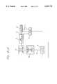
- FIG. 1is a schematic diagram of an ablation apparatus including a power control system, electrode device and backplate;
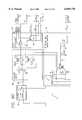
- FIGS. 2-1 and 2-2 formis a block diagram presenting more detail of a power control system in accordance with aspects of the invention, showing phase angle control, duty cycle control, and impedance and temperature monitoring;
- FIG. 3is a diagram of a multi-channel ablation apparatus in accordance with aspects of the invention wherein a single microprocessor controls the phase angle and duty cycle of each channel individually;
- FIG. 4depicts a first power waveform having a first phase angle and alternating instances of peak power and very low power
- FIG. 5depicts a second power waveform having a second phase angle different from the first phase angle and alternating instances of peak power and very low power;
- FIG. 6presents a time frame (TF) diagram showing a fifty-percent duty cycle
- FIG. 7Adepicts the phase relationship and voltage potential between the first and second power waveforms having first and second phase angles respectively, as a function of time
- FIG. 7Bdepicts the phase relationship and voltage potential between the first and second power waveforms having second and first phase angles respectively, as a function of time
- FIGS. 8A, 8B, 8C, 8D, and 8Eare schematic diagrams of an embodiment of a power control system in accordance with aspects of the invention with FIG. 8A showing how FIGS. 8B, 8C, 8D and 8E are related;
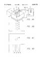
- FIG. 9Ais a three dimensional representation of an ablation apparatus having a linear array of band electrodes in contact with a biological site with a backplate at the opposite side of the biological site, in which the phase angle difference between adjacent electrodes of the linear array is zero degrees;
- FIGS. 9B through 9Ddepict, along the x, y, and z axes shown, the depth of the lesions formed by the ablation apparatus of FIG. 9A showing that the apparatus acts as a unipolar device with multiple electrodes and the resulting lesions are discontinuous;
- FIG. 10Ais a three dimensional representation of an ablation apparatus having a linear array of band electrodes in contact with a biological site with a backplate at the opposite side of the biological site, in which the phase angle difference between adjacent electrodes is 180 degrees;
- FIGS. 10B through 10Ddepict, along the x, y, and z axes shown, the continuity and depth of a lesion formed by the ablation apparatus of FIG. 10A showing that the apparatus acts as a bipolar device with no significant amount of current flowing to the backplate;
- FIG. 11Ais a three dimensional representation of an ablation apparatus having a linear array of band electrodes in contact with a biological site with a backplate at the opposite side of the biological site, in which the phase difference between adjacent electrodes is approximately 90 degrees;
- FIGS. 11B through 11Ddepict, along the x, y, and z axes shown, the continuity and depth of a lesion formed by the ablation apparatus of FIG. 11A showing the greater depth of lesion resulting from the phase angle difference.
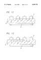
- FIG. 12presents a block diagram of the current flow among electrodes and the backplate through the biological site for adjacent electrodes having different phase angles
- FIG. 13presents the same block diagram as FIG. 12 with the phase angles between adjacent electrodes reversed.
- FIGS. 14A through 14Dpresent, along the x, y, and z axes shown, the increased continuity, depth, and uniformity of a lesion formed by the alternating phase apparatus and method shown in previous figures.
- FIG. 1there is shown an ablation apparatus 10 in accordance with aspects of the present invention.
- the apparatus 10includes a power control system 12 that provides power or drive 14 to an electrode device 16.
- the power control system 12comprises a power generator 18 that may have any number of output channels through which it provides the power 14.
- the operation of the power generator 18is controlled by a controller 20 which outputs control signals 21 to the power generator 18.
- the controller 20monitors the power 14 provided by the power generator 18.
- the controller 20also receives temperature signals 22 from the electrode device 16. Based on the power 14 and temperature signals 22 the controller 20 adjusts the operation of the power generator 18.
- a backplate 24is located proximal to the biological site 26 opposite the site from the electrode device 16, and is connected by a backplate wire 28 to the power generator 18.
- the backplate 24is set at the reference level to the power provided to the electrodes, as discussed in detail below.
- the electrode device 16is typically part of a steerable EP catheter 30 capable of being percutaneously introduced into a biological site 26, e. g., the atrium or ventricle of the heart.
- the electrode device 16is shown in schematic form with the components drawn to more clearly illustrate the relationship between the components and the relationship between the components and the power control system 12.
- the catheter 30comprises a distal segment 34 and a handle 31 located outside the patient.
- a preferred embodiment of the electrode device 16includes twelve band electrodes 32 arranged in a substantially linear array along the distal segment 34 of the catheter 30.
- the electrode device 16may include a tip electrode 36.
- band electrodes 32are arranged so that there is space 38 between adjacent electrodes.
- the width of the band electrodes 32is 3 mm and the space 38 between the electrodes is 4 mm.
- the total length of the electrode device 16, as such,is approximately 8 cm.
- the arrangement of the band electrodes 32is not limited to a linear array and may take the form of other patterns.
- a substantially linear arrayis preferred for certain therapeutic procedures, such as treatment of atrial fibrillation, in which linear lesions of typically 4 to 8 cm in length are desired.
- a linear arrayis more easily carried by the catheter 30 and also lessens the size of the catheter.
- the band electrodes 32are formed of a material having a significantly higher thermal conductivity than that of the biological tissue 26. Possible materials include silver, copper, gold, chromium, aluminum, molybdenum, tungsten, nickel, platinum, and platinum/10% iridium. Because of the difference in thermal conductivity between the electrodes 32 and the tissue 26, the electrodes 32 cool off more rapidly in the flowing fluids at the biological site. The power supplied to the electrodes 32 may be adjusted during ablation to allow for the cooling of the electrodes while at the same time allowing for the temperature of the tissue to build up so that ablation results.
- the electrodes 32are sized so that the surface area available for contact with fluid in the heart, e. g., blood, is sufficient to allow for efficient heat dissipation from the electrodes to the surrounding blood. In a preferred embodiment, the electrodes 32 are 7 French (2.3 mm in diameter) with a length of 3 mm.
- the thickness of the band electrodes 32also affects the ability of the electrode to draw thermal energy away from the tissue it contacts.
- the electrodes 32are kept substantially thin so that the electrodes effectively draw energy away from the tissue without having to unduly increase the outer diameter of the electrode.
- the thickness of the band electrodesis 0.05 to 0.13 mm (0.002 to 0.005 inches).
- each band electrode 32has a temperature sensor 40 mounted to it.
- Each temperature sensor 40provides a temperature signal 22 to the controller 20 which is indicative of the temperature of the respective band electrode 32 at that sensor.
- a temperature sensor 40is mounted on every other band electrode 32.
- every other electrodehas two temperature sensors 40.
- FIG. 1which shows an embodiment having one temperature sensor for each electrode, there is shown a single power lead 15 for each electrode 32 to provide power to each electrode for ablation purposes and two temperature leads 23 for each temperature sensor 40 to establish the thermocouple effect.
- the drive wiremay comprise one of the thermocouple wires or may comprise a common wire for a plurality of thermocouples mounted on the same electrode.
- the inventorhereby incorporates by reference his pending application Ser. No. 09/072,800 entitled “Catheter Having Common Lead for Electrode and Sensor” filed May 5, 1998, and his pending application Ser. No. 09/072,853 entitled “Electrode Having Non-Joined Thermocouple for Providing Multiple Temperature-Sensitive Junctions” filed May 5, 1998.
- FIGS. 2-1 and 2-2a block diagram of an ablation apparatus 10 and method in accordance with aspects of the invention is presented.
- a single channel of the power control system 12is depicted. This channel controls the application of power to a single electrode 32.
- a channelmay control a plurality or group of electrodes.
- a microprocessor 42which is part of the controller 20 (FIG. 1), provides a duty cycle control signal 44 to a duty cycle generator (“DCG") 45.
- the duty cycle generator 45receives the control signal 44 by an 8-bit latch 46.
- the latch 46provides an 8-bit signal 47 to a duty cycle comparator 48.
- the comparator 48compares the 8-bit signal 47 to a count from an 8-bit duty cycle counter 50 and if the count is the same, provides a duty cycle off signal 49 to the duty cycle gate 52.
- the gate 52is connected to a frequency source ("F5") 54, such as an oscillator that produces 500 kHz.
- F5"frequency source
- an 8-bit controlhas a period or time frame of 0.5 msec.
- the electrodeis in the off period only 0.25 msec.
- the period or time frame 78(FIG. 6) is lengthened by use of a prescalar 56 interposed between the frequency source 54 and the counter 50.
- the prescalar 56lengthens the period to 4 msec thus allowing for a 2 msec off period during a fifty-percent duty cycle. This results in a sufficient cooling time for the very thin band electrodes discussed above. Other lengths of the period may be used depending on the circumstances.
- a terminal count detector 58detects the last count of the period and sends a terminal count signal 59 to the gate 52 which resets the gate for continued output of the frequency source signal. This then begins the on period of the duty cycle and the counter 50 begins its count again.
- the duty cycleis set at fifty percent and the 8-bit latch is accordingly set to 128. In another embodiment, the duty cycle is set at ten percent.
- a programmable logic array (“PLA”) 60receives phase control signals 61 from the microprocessor 42 and controls the phase of the frequency source 54 accordingly.
- the PLA 60receives the terminal count signal 59 from the terminal count detector 58 and only permits phase changes after receiving that terminal count signal.
- the output signal from the gate 52 during the on period of the duty cycleis provided to a binary power amplifier (“BPA”) 62 that increases the signal to a higher level, in this case, 24 volts.
- BPAbinary power amplifier
- the amplified signalsare then filtered with a band pass filter (“BPF") 64 to convert the somewhat square wave to a sine wave.
- the band pass filter 64in one embodiment is centered at 500 kHz.
- the filtered signalis then provided to an isolated output transformer (“10T”) 66 that amplifies the signal to a much higher level, for example 350 volts peak-to-peak. This signal is then sent to a relay interconnect (“R1”) 67 before it is provided as a power output signal OUTn 14 to an electrode 32 at the biological site to cause ablation.
- R1relay interconnect
- the power output signal 14 from the isolated output transformer 66is monitored in one embodiment to determine the impedance at the electrode 32.
- a voltage and current monitor (“VCM”) 68is used in the embodiment shown in (FIGS. 2-1 and 2-2).
- the monitor signal 69is converted to digital form by an A-to-D converter (“ADC”) 70 and provided to the microprocessor 42.
- ADCA-to-D converter
- some or all of the electrodes 32may include a temperature sensor 40 (FIG. 1) that provides temperature signals 22 (FIG. 2-2) which are used to determine the temperature at the electrode 32.
- the power 14, in conjunction with the temperature signals 22,are used to determine the temperature at the electrode 32.
- Both the temperature signals 22 and the power 14pass through a temperature filter 73 before being sent to the microprocessor 42.
- the temperature filter (“FL") 73is contained in a printed circuit board separate from the controller 20 and contains its own processor. In either case, the filter 73 filters out any RF noise present in the power 14 so that the signal may be used for temperature monitoring purposes.
- the microprocessormonitors the power 14 and temperature signals 22 only during the off periods of the power 14 duty cycle. Accordingly, negligible RF noise is present in the power line and filtration is not necessary.
- the microprocessor 42may alter the duty cycle of the power 14 in response to either or both of the impedance or temperature signals.
- the temperature sensed and/or the determined impedancemay be displayed to an operator.
- the operatorin response may then manually control the duty cycle or other power parameters such as by rotating a knob mounted on a front panel of an instrument.
- a knob mounted on a front panel of an instrumentIn the case of a multiple channel instrument and catheter, as discussed below, multiple knobs may be provided in this manual arrangement for control over each channel.
- FIG. 3a multiple channel ablation apparatus is shown. Although only three complete channels are shown, the apparatus comprises many more as indicated by the successive dots. Those channels are not shown in FIG. 3 to preserve clarity of illustration.
- By providing different voltage levels between two electrodes 32 in an arraycurrent flows between those electrodes in a bipolar electrode approach.
- By setting the backplate 24 (FIG. 1)at a voltage level different from at least one of those electrodes 32, current flows between that electrode and the backplate.
- the current flow through the biological site 26can be more precisely controlled.
- One technique for setting different voltage levels between the electrodes 32is to maintain a phase difference between them in an AC approach. By setting the backplate 24 at the reference level, current flows between the electrodes 32 and the backplate.
- the single microprocessor 42which again is part of the controller 20 (FIG. 1), controls the duty cycle and the phase of each channel individually in this embodiment.
- Each channel showncomprises the same elements and each channel produces its own power output signal 14 (OUT1, OUT2, through OUTn where "n" is the total number of channels) on respective electrode leads (LEAD 1, LEAD 2, through LEAD n where "n" is the total number of leads) to the electrodes 32.
- This multi-channel approachpermits more individual control over each electrode.
- the duty cycle of the power applied to each electrodecan be individually controlled.
- One electrodemay have a ten percent duty cycle while another has a thirty percent duty cycle.
- the signalsas shown in FIGS. 4, 5, and 6, have alternating instances of peak power i.e., "on” periods 74, and very low power 76, i.e., "off” periods.
- the output power 14is a 500 kHz sine wave.
- the number of cycles of the sine wave contained within one on period 74has been substantially reduced in the drawing to emphasize the phase difference between the first and second output signals OUT1, OUT2.
- the voltage of each power signal 14 during an off period 76is substantially zero and during an on period 74 is approximately 350 volts peak-to-peak.
- the power OUT1 and OUT2also have a variable duty cycle for controlling the length of the on period 74 and the off-period 76 within a time frame 78 (see FIG. 6).
- the duty cycleis the ratio of the length of the on period 74 to the length of the entire time frame 78.
- the effective poweris the peak power times the duty cycle. Thus, a signal having a peak power of 100 watts and a 50% duty cycle has an effective power of 50 watts.
- the two power signals OUT1, OUT2are phased differently from each other.
- the phase angle of each power signalis set and controlled by the processor 42 and PLA 60.
- Each power signal OUT1 and OUT2has a respective phase angle and those phase angles differ between the two of them.
- the phase angle difference between the power OUT1 and OUT2produces a voltage potential between the band electrodes 32 (FIG. 1) network.
- the FETs Q2 through Q5are nonconducting and no power is sent to the bandpass filter 64. Instead the FETs Q2 through Q5 present a high impedance load to any signals received through the electrode 32.
- the load impedance on the FETs Q2 through Q5 presented by the circuit following the FETs , the electrode, and the tissueis approximately 150 ⁇ but transformed through the output transformer T3, it presents a load impedance to the FETs Q2-Q5 of approximately 0.5 to 1 ⁇ .
- the FETsIn the off state, the FETs present an impedance of approximately 250 ⁇ which is large in comparison to the transformed load impedance of approximately 0.5 to 1 ⁇ . Therefore, very little power flows when the FETs are in the off state.
- the bandpass filter 64operates to shape the output signal provided by the binary amplifier 62 from a square wave to a sinusoidal wave.
- the filtered signal 85then passes to the isolated output section 66 where it is step-up transformed to 350 volt peak-to-peak sinusoidal power at T3.
- the poweris then split into two identical power signals OUT1A, OUT1B and provided to two or more respective band electrodes 32 on the output lines LEAD1A, LEAD1B.
- the isolated output section 66also includes relays 88 that may be individually opened to remove the power signals OUT1A, OUT1B from the electrode leads LEAD 1A, LEAD 1B when an alert condition is detected, such as high temperature or high impedance at the respective electrode 32. As previously mentioned these conditions are determined by the microprocessor 42 which receives signals indicative of the temperature and impedance at each of the band electrodes 32.
- the power from the isolated output section 66is monitored and representative signals are supplied to an RF voltage and current monitor 68 where in this case, the voltage and current of each output signal are measured to determine the impedance of the particular channel.
- the measured signalsare sent to an A-to-D converter 70 (FIG. 2-2) before being sent to the microprocessor 42 for impedance monitoring. If the impedance is above a threshold level indicative of blood clotting or boiling, the microprocessor 42 sends a signal to the duty cycle generator 45 to reduce or discontinue the duty cycle of the power OUT1A, OUT1B and thus lower the effective power delivered to the band electrodes 32.
- the temperature at the electrodes 32is determined by monitoring the power 14 and temperature signals 22 and measuring the voltage difference between the signals. As previously mentioned, in one embodiment of the invention, these signals pass through a filter 73 (FIG. 2-2) before being sent to the microprocessor 42. The voltage value is converted to a temperature and if the temperature is above a threshold level the duty cycle of the power 14 is reduced. In the case where a single lead is used to provide a signal which is used to determine the temperature as well as provide power to the electrode 32, the signal from the lead is received on temperature leads 87, 89 connected at the output side of the relays 88.
- the duty cycle of each electrode 32may be individually controlled by the microprocessor 42. As previously mentioned, based on the temperature at an electrode 32 and the current and voltage of the output signal provided to an electrode, the duty cycle of the output signal may be adjusted. For example, one electrode 32 may have a temperature requiring a duty cycle of ten percent, while another electrode may have a temperature which allows for a fifty percent duty cycle. In an embodiment in which every other electrode 32 has a temperature sensor 40, the electrodes are grouped in pairs with each electrode in the pair having the same duty cycle.
- the electrode device 16 and the backplate 24are positioned proximal the biological site 26 undergoing ablation such that the biological site is interposed between the electrode device and the backplate.
- the band electrodes 32(only one of which is indicated by a numeral 32 for clarity of illustration) of the electrode device 16 each receives power OUT1, OUT2, OUT3, OUT4 having a phase angle on LEAD 1 through LEAD 4.
- every other electrode 32receives the same phase angle. Therefore, the phase angle of electrode A equals the phase angle of electrode C and the phase angle of electrode B equals the phase angle of electrode D.
- the electrodes 32are formed into a linear array as shown.
- a thermocouple temperature sensor 40is located at each of the electrodes A, B, C, and D and uses the electrode power lead LEADS 1 through 4 as one of the sensor leads. The sensors 40 provide temperature sensor signals 22 for receipt by the power control system 12.
- alternate electrodes 32may be grouped together and each may receive the same power having the same phase angle and duty cycle. Another group or groups of electrodes 32 may be interspaced with the first group such that the electrodes of one group alternate with the electrodes of the other group or groups. Each electrode 32 in a particular group of electrodes has the same phase angle and duty cycle. For example, electrodes A and C may be connected to the same power while interspaced electrodes B and D may be connected to a different power output signal.
- the use of individual power signalsalso provides the ability to disable any combination of electrodes 32 and thereby effectively change the length of the electrode device 16.
- an electrode device 16 with twelve electrodes 32receives twelve power signals from a twelve channel power control system 12.
- the electrodes 32are 3 mm in length and are 4 mm apart. Accordingly, by disabling various electrodes, a virtual electrode of any length from 3 mm to 8 cm may be produced by the electrode device 16.
- the backplate 24is maintained at the reference voltage level in regard to the voltage level of the power OUT1 through OUTn.
- phase angle differenceis established between adjacent band electrodes.
- This phase angle differencemay be adjusted to control the voltage potential between adjacent band electrodes 32 and thus to control the flow of current through the biological site 26.
- the flow of current I e-e between adjacent band electrodes 32is defined by: that receive the power. This voltage potential, in turn, induces current flow between the band electrodes 32.
- the phase angle relationship of the power and the voltage potential produced as a function of timeis shown in FIGS. 7A and 7B.
- FIG. 7Ashows first and second power OUT1 and OUT2 provided to first and second electrodes respectively having a phase angle difference ⁇ with OUT1 leading OUT2 by 132 degrees.
- FIG. 7Bshows the same power OUT1 and OUT2 but with the phase angles reversed where OUT2 is now leading OUT 1 by 132 degrees.
- FIGS. 8A through 8Eschematic diagrams of an embodiment of the ablation apparatus 10 of FIGS. 2-1 and 2-2 are presented in FIGS. 8B through 8E while FIG. 8A shows how FIGS. 8B through 8E should be oriented in relation to each other.
- the frequency source 54provides a signal 80, typically at 500 kHz with a phase angle controlled by the microprocessor 42 through the PLA 60, to the duty cycle generator 45.
- the duty cycle generator 45modulates the frequency source signal 80 to produce the selected duty cycle in accordance with the duty cycle control signal 44 as previously described.
- the duty cycle generator 45outputs two signals 82 and 84 to the binary power amplifier 62.
- a dual MOSFET driver U2receives the signals, converts their 5 V level to a 12 V level, and sends each to a transformer T2 which transforms the signals into 24 V peak-to-peak power.
- the 24 V poweris then sent to a multi-state driver 86 which includes a configuration of FETs Q2, Q3, Q4, and Q5.
- FIGS. 9A through 11Dillustrate various current flow patterns within a biological site.
- the depths and widths of the lesions depicted in FIGS. 9 through 11are not necessarily to scale or in scalar proportion to each other but are provided for clarity in discerning the differences between the various power application techniques.
- the phase difference between adjacent electrodes 32is zero degrees, no current flows between the electrodes in accordance with Eq. 2 above, and the apparatus operates in a unipolar fashion with the current flowing to the backplate 24 as shown in FIGS. 9A through 9D.
- the lesionsare discrete.
- the lesions 90are discontinuous in regard to each other.
- the apparatusWhen the phase difference between adjacent electrodes 32 is 180 degrees the apparatus operates in both a unipolar and bipolar fashion and the current flow pattern is as shown in FIG. 10A. With this phase difference, approximately twice as much current flows between adjacent band electrodes 32 than flows from the band electrodes to the backplate 24. The resulting lesion 92 is shallow but is continuous along the length of the electrode device 16. The continuity and shallow depth of the lesion 92 are illustrated in FIGS. 10B through 10D. Nevertheless, the lesion depth is still greater than that created by prior bipolar ablation methods alone.
- the phase difference between adjacent electrodes 32When the phase difference between adjacent electrodes 32 is set within the range of a value greater than zero to less than 180 degrees, the current flow varies from a deep, discontinuous unipolar pattern to a more continuous, shallow bipolar pattern. For example, when the phase difference between adjacent electrodes 32 is around 90 degrees, the current flows as shown in FIG. 11A. With this phase difference, current flows between adjacent band electrodes 32 as well as between the band electrodes and the backplate 24. Accordingly, a lesion which is both deep and continuous along the length of the electrode device 16 is produced. The continuity and depth of the lesion 94 is illustrated in FIGS. 11B through 11D.
- adjacent electrodesalternated in phase but were provided with power in groups. Electrodes A and C were provided with power at a first phase angle and electrodes B and D were provided with power at a second phase angle, different from the first.
- the phase angle of the powermay be adjusted in order to produce a lesion having different depth and continuity characteristics.
- other elements of the electrode device 16are considered.
- the width of the band electrodes 32 and the spacing between the electrodesare factors in selecting an optimum phase angle.
- the width of the band electrodesis 3 mm
- the spacing between the electrodesis 4 mm
- the electrodesreceive power which establish a phase difference of 132 degrees between adjacent electrodes.
- energyis applied to the biological tissue 26 during the on period of the duty cycle in an alternating unipolar-bipolar manner.
- a voltage potentialis established between the electrodes 32 and the backplate 24.
- currentflows through the tissue 26 between the electrodes 32 and the backplate 24.
- a voltage potentialis established between at least two of the electrodes 32 rather than between the electrodes and the backplate 24.
- currentflows through the tissue 26 between the electrodes 32.
- the voltage difference between the electrodes 32may be established by providing power with different phase angles to the electrodes as previously mentioned.
- some of the electrodes 32may be connected to a reference potential while others are maintained at a different voltage level.
- the continuity and depth of the lesion producedmay be controlled. For example, operating in the unipolar mode for one-fourth of the on period and in the bipolar mode for three-fourths of the on period produces a lesion having a continuity and depth similar to the lesion 94 illustrated in FIGS. 11B through 11D.
- FIGS. 8B through and 8Ethe following devices are shown:
- the transformer denoted by “T3”is a 1:12 turns ratio, single turn primary, step up transformer wound on a TDK core PC50EER23Z.
- FIG. 12presents a block diagram of the current flow among electrodes 32 and the backplate 24 through the biological site 26 for adjacent electrodes having different phase angles where the phase angles of the A and C electrodes lead the phase angles of the B and D electrodes. It has been noted that with the approach shown in FIG. 12, the vector sum of the currents flowing through the site 26 is such that more current flows at one or more electrodes than at others. This is shown figuratively with shorter arrows leading to the backplate from the B and D electrodes. Although the ablation volume is greater than in the prior techniques, the ablation volume appears irregular or nonuniform as shown in FIG. 11D. It is desirable to have a more uniform ablation volume, especially as to depth, so that irregular electrical signals do not pass under the ablation volume at a point having less depth and require a repeat of the ablation procedure.
- FIG. 13presents the same block diagram as FIG. 12 with the phase angles between adjacent electrodes reversed.
- the phase angles of the power at the B and D electrodes 32now lead the phase angles of the power at the A and C electrodes 32.
- the change in current flow due to this opposite phasingis represented figuratively with shorter arrows now at the A and C electrodes thus balancing the current flow pattern of FIG. 12. It has been found that by alternating the phase angles such as shown in FIGS. 12 and 13, a much more uniform current flow and much more uniform ablation volume result.
- a cumulative effect of the current flowcauses the tissue between all the band electrodes 32 and the backplate 24 to become ablated, depth-wise through the biological site 26, at a substantially even rate and thus a lesion having substantially uniform depth is produced.
- FIGS. 14A through 14Dwhere an ablation volume 96 is shown, which has much greater uniformity in shape.
- the ablation lesion 96has a uniform depth and gives rise to a high level of confidence that the ablation volume created with the ablation apparatus in accordance with the invention will successfully destroy the tissue causing the arrhythmia.
- the phase between the electrodeswas alternated as shown in FIGS. 12 and 13 only during the off period of the duty cycle. That is, and with reference to FIG. 6, during the entire on period 74 of the duty cycle of one time frame 78, the phase angles of the power at the A and C electrodes 32 led the phase angles of the power at the B and D electrodes 32 by 132 degrees.
- the phase angles of the power to be suppliedwas changed to be opposite those phase angles used during the on period 74, in preparation for the next on period. Then at the next on period 74, the phase angles of the power provided to electrodes B and D led the phase angles of the power provided to the A and C electrodes by 132 degrees during that entire on period. During the immediately subsequent off period, the phase angles were again changed so that electrodes A and C would lead electrodes B and D.
- controller 20is shown in FIG. 1 as forming a part of the power control system 12.
- itmay take other forms such as an external processor in a separate computer for example.
- duty cycle control and phase controlmay be performed by circuits other than those shown here. Accordingly, it is not intended that the invention be limited, except as by the appended claims.
Landscapes
- Health & Medical Sciences (AREA)
- Surgery (AREA)
- Engineering & Computer Science (AREA)
- Life Sciences & Earth Sciences (AREA)
- Biomedical Technology (AREA)
- Molecular Biology (AREA)
- Nuclear Medicine, Radiotherapy & Molecular Imaging (AREA)
- Plasma & Fusion (AREA)
- Physics & Mathematics (AREA)
- Heart & Thoracic Surgery (AREA)
- Medical Informatics (AREA)
- Otolaryngology (AREA)
- Animal Behavior & Ethology (AREA)
- General Health & Medical Sciences (AREA)
- Public Health (AREA)
- Veterinary Medicine (AREA)
- Cardiology (AREA)
- Surgical Instruments (AREA)
Abstract
Description
______________________________________ Device Part No. Manufacturer ______________________________________ U1 GAL6002B Lattice U2 SN75372 numerous Q1 1RFZ34N numerous Q2, Q3, Q4, Q5 1RFZ44N numerous Q7, Q8, Q9 MPF6601 numerous R3, R5 1Ω numerous T1, T4 CMI-4810 Corona Magnetics, Inc. T2 GFS97-0131-1 GFS Manufacturing T5 CMI-4809 Corona Magnetics, Inc. ______________________________________
Claims (46)
Priority Applications (9)
| Application Number | Priority Date | Filing Date | Title |
|---|---|---|---|
| US09/073,392US6059778A (en) | 1998-05-05 | 1998-05-05 | RF ablation apparatus and method using unipolar and bipolar techniques |
| CA002327322ACA2327322A1 (en) | 1998-05-05 | 1999-04-28 | Rf ablation apparatus and method using unipolar and bipolar techniques |
| EP99920122AEP1076520A1 (en) | 1998-05-05 | 1999-04-28 | Rf ablation apparatus and method using unipolar and bipolar techniques |
| JP2000546681AJP2002513617A (en) | 1998-05-05 | 1999-04-28 | RF ablation device and method using monopolar and bipolar technology |
| PCT/US1999/009238WO1999056644A1 (en) | 1998-05-05 | 1999-04-28 | Rf ablation apparatus and method using unipolar and bipolar techniques |
| US09/501,472US6200314B1 (en) | 1998-05-05 | 2000-02-09 | RF ablation apparatus and method using unipolar and bipolar techniques |
| US09/738,032US6558378B2 (en) | 1998-05-05 | 2000-12-13 | RF ablation system and method having automatic temperature control |
| US09/758,636US6488678B2 (en) | 1998-05-05 | 2001-01-10 | RF ablation apparatus and method using unipolar and bipolar techniques |
| US10/400,770US20030195501A1 (en) | 1998-05-05 | 2003-03-27 | RF ablation system and method having automatic temperature control |
Applications Claiming Priority (1)
| Application Number | Priority Date | Filing Date | Title |
|---|---|---|---|
| US09/073,392US6059778A (en) | 1998-05-05 | 1998-05-05 | RF ablation apparatus and method using unipolar and bipolar techniques |
Related Child Applications (1)
| Application Number | Title | Priority Date | Filing Date |
|---|---|---|---|
| US09/501,472DivisionUS6200314B1 (en) | 1998-05-05 | 2000-02-09 | RF ablation apparatus and method using unipolar and bipolar techniques |
Publications (1)
| Publication Number | Publication Date |
|---|---|
| US6059778Atrue US6059778A (en) | 2000-05-09 |
Family
ID=22113433
Family Applications (3)
| Application Number | Title | Priority Date | Filing Date |
|---|---|---|---|
| US09/073,392Expired - LifetimeUS6059778A (en) | 1998-05-05 | 1998-05-05 | RF ablation apparatus and method using unipolar and bipolar techniques |
| US09/501,472Expired - LifetimeUS6200314B1 (en) | 1998-05-05 | 2000-02-09 | RF ablation apparatus and method using unipolar and bipolar techniques |
| US09/758,636Expired - LifetimeUS6488678B2 (en) | 1998-05-05 | 2001-01-10 | RF ablation apparatus and method using unipolar and bipolar techniques |
Family Applications After (2)
| Application Number | Title | Priority Date | Filing Date |
|---|---|---|---|
| US09/501,472Expired - LifetimeUS6200314B1 (en) | 1998-05-05 | 2000-02-09 | RF ablation apparatus and method using unipolar and bipolar techniques |
| US09/758,636Expired - LifetimeUS6488678B2 (en) | 1998-05-05 | 2001-01-10 | RF ablation apparatus and method using unipolar and bipolar techniques |
Country Status (5)
| Country | Link |
|---|---|
| US (3) | US6059778A (en) |
| EP (1) | EP1076520A1 (en) |
| JP (1) | JP2002513617A (en) |
| CA (1) | CA2327322A1 (en) |
| WO (1) | WO1999056644A1 (en) |
Cited By (101)
| Publication number | Priority date | Publication date | Assignee | Title |
|---|---|---|---|---|
| US6287306B1 (en)* | 1998-06-22 | 2001-09-11 | Daig Corporation | Even temperature linear lesion ablation catheter |
| US20020052599A1 (en)* | 2000-10-31 | 2002-05-02 | Gyrus Medical Limited | Electrosurgical system |
| WO2002047565A3 (en)* | 2000-12-13 | 2002-08-22 | Cardiac Pacemakers Inc | Rf ablation system and method having automatic temperature control |
| WO2002089890A2 (en) | 2001-05-02 | 2002-11-14 | Cardiac Pacemakers, Inc. | Dual-profile steerable catheter |
| WO2002094115A2 (en) | 2001-05-24 | 2002-11-28 | Cardiac Pacemakers, Inc. | Twin coaxial catheters for rf pulmonary vein ablation |
| US20030036754A1 (en)* | 1998-10-23 | 2003-02-20 | Lyndall Erb | Vacuum-assisted securing apparatus for a microwave ablation instrument |
| US6635056B2 (en)* | 2001-10-09 | 2003-10-21 | Cardiac Pacemakers, Inc. | RF ablation apparatus and method using amplitude control |
| US20040059322A1 (en)* | 2002-09-04 | 2004-03-25 | Toshikazu Kawai | Medical manipulator system and operating method thereof |
| US6730078B2 (en) | 2002-04-22 | 2004-05-04 | Cardiac Pacemakers, Inc. | RF ablation apparatus and method using multi-frequency energy delivery |
| US6743225B2 (en) | 2001-03-27 | 2004-06-01 | Uab Research Foundation | Electrophysiologic measure of endpoints for ablation lesions created in fibrillating substrates |
| US20040260278A1 (en)* | 1996-10-22 | 2004-12-23 | Anderson Scott C. | Apparatus and method for ablating tissue |
| US20040267186A1 (en)* | 2003-06-27 | 2004-12-30 | Dextradeur Alan J. | System and method for clearing an implanted catheter that is connected to a shunt |
| US20050033137A1 (en)* | 2002-10-25 | 2005-02-10 | The Regents Of The University Of Michigan | Ablation catheters and methods for their use |
| US20050059448A1 (en)* | 2003-09-11 | 2005-03-17 | Scott Sims | Method and apparatus for playing card game |
| US6869414B2 (en) | 2002-03-22 | 2005-03-22 | Cardiac Pacemakers, Inc. | Pre-shaped catheter with proximal articulation and pre-formed distal end |
| US20050096644A1 (en)* | 2003-10-30 | 2005-05-05 | Hall Jeffrey A. | Energy delivery optimization for RF duty cycle for lesion creation |
| US20050101948A1 (en)* | 2000-08-23 | 2005-05-12 | Olympus Optical Co., Ltd. | Electric operation apparatus |
| US20050203507A1 (en)* | 2004-03-12 | 2005-09-15 | Surgrx, Inc. | Electrosurgical instrument and method of use |
| US20050251132A1 (en)* | 2002-10-25 | 2005-11-10 | Regents Of The University Of Michigan | Ablation catheters |
| US6976986B2 (en) | 2000-04-12 | 2005-12-20 | Afx, Inc. | Electrode arrangement for use in a medical instrument |
| US20060025838A1 (en)* | 1999-04-16 | 2006-02-02 | Laufer Michael D | Device for shaping infarcted heart tissue and method of using the device |
| US20060069388A1 (en)* | 2002-04-30 | 2006-03-30 | Csaba Truckai | Electrosurgical instrument and method |
| US7033352B1 (en) | 2000-01-18 | 2006-04-25 | Afx, Inc. | Flexible ablation instrument |
| US20060111701A1 (en)* | 2004-11-24 | 2006-05-25 | Ablation Frontiers, Inc. | Atrial ablation catheter adapted for treatment of septal wall arrhythmogenic foci and method of use |
| US20060111700A1 (en)* | 2004-11-24 | 2006-05-25 | Ablation Frontiers, Inc. | Atrial ablation catheter and method of use |
| US20060155241A1 (en)* | 2000-12-29 | 2006-07-13 | Constantz Brent R | Proton generating catheters and methods for their use in enhancing fluid flow through a vascular site occupied by a calcified vascular occlusion |
| US20060161229A1 (en)* | 2005-01-14 | 2006-07-20 | Laufer Michael D | System and method for the treatment of heart tissue |
| US7099717B2 (en) | 2002-01-03 | 2006-08-29 | Afx Inc. | Catheter having improved steering |
| US20060293714A1 (en)* | 2005-06-28 | 2006-12-28 | Rodney Salo | Method and apparatus for controlling cardiac therapy based on electromechanical timing |
| US7192427B2 (en) | 2002-02-19 | 2007-03-20 | Afx, Inc. | Apparatus and method for assessing transmurality of a tissue ablation |
| US20070073284A1 (en)* | 2002-09-25 | 2007-03-29 | Sturm Thomas A | Multiple RF return pad contact detection system |
| US7226446B1 (en) | 1999-05-04 | 2007-06-05 | Dinesh Mody | Surgical microwave ablation assembly |
| US20070156209A1 (en)* | 2005-01-14 | 2007-07-05 | Co-Repair, Inc. | System for the treatment of heart tissue |
| US20070156210A1 (en)* | 2005-01-14 | 2007-07-05 | Co-Repair, Inc., A California Corporation | Method for the treatment of heart tissue |
| US20070191827A1 (en)* | 2006-01-17 | 2007-08-16 | Endymion Medical Ltd. | Electrosurgical methods and devices employing phase-controlled radiofrequency energy |
| US20070203481A1 (en)* | 2003-10-23 | 2007-08-30 | Gregg William N | Redundant Temperature Monitoring In Electrosurgical Systems for Saftey Mitigation |
| US20070244478A1 (en)* | 2006-04-18 | 2007-10-18 | Sherwood Services Ag | System and method for reducing patient return electrode current concentrations |
| US7303560B2 (en) | 2000-12-29 | 2007-12-04 | Afx, Inc. | Method of positioning a medical instrument |
| US20080033276A1 (en)* | 2001-06-01 | 2008-02-07 | Ehr Chris J | Return Pad Cable Connector |
| US20080045942A1 (en)* | 2001-10-22 | 2008-02-21 | Surgrx, Inc. | Electrosurgical instrument and method of use |
| US7346399B2 (en) | 1999-05-28 | 2008-03-18 | Afx, Inc. | Monopole tip for ablation catheter |
| US20080082097A1 (en)* | 2006-09-28 | 2008-04-03 | Sherwood Services Ag | Smart return electrode pad |
| US20080114350A1 (en)* | 2005-07-15 | 2008-05-15 | Park Christopher J | Matrix router for surgical ablation |
| US20080147040A1 (en)* | 2006-12-13 | 2008-06-19 | Medtronic Vascular, Inc. A Delaware Corporation | Catheters Having Linear Electrode Arrays and Their Methods of Use |
| US20080172048A1 (en)* | 2007-01-12 | 2008-07-17 | Keith Edward Martin | Ablation system, clamp and method of use |
| US7419490B2 (en) | 2006-07-27 | 2008-09-02 | Applied Medical Resources Corporation | Bipolar electrosurgical scissors |
| US20080249524A1 (en)* | 2007-04-03 | 2008-10-09 | Tyco Healthcare Group Lp | System and method for providing even heat distribution and cooling return pads |
| US20080249521A1 (en)* | 2007-04-03 | 2008-10-09 | Tyco Healthcare Group Lp | System and method for providing even heat distribution and cooling return pads |
| US20080281310A1 (en)* | 2007-05-11 | 2008-11-13 | Tyco Healthcare Group Lp | Temperature monitoring return electrode |
| US20080300643A1 (en)* | 2002-01-04 | 2008-12-04 | Rodney Salo | Heart failure therapy adjustment based on ventricular pressures |
| US20090198230A1 (en)* | 2008-02-04 | 2009-08-06 | Behnke Robert J | System and Method for Return Electrode Monitoring |
| US20090306647A1 (en)* | 2008-06-05 | 2009-12-10 | Greg Leyh | Dynamically controllable multi-electrode apparatus & methods |
| US20090318917A1 (en)* | 2008-06-05 | 2009-12-24 | Greg Leyh | Subcutaneous electric field distribution system and methods |
| US20090318916A1 (en)* | 2007-03-01 | 2009-12-24 | Daniel Lischinsky | Electrosurgical Methods and Devices Employing Semiconductor Chips |
| US7637907B2 (en) | 2006-09-19 | 2009-12-29 | Covidien Ag | System and method for return electrode monitoring |
| US20100022999A1 (en)* | 2008-07-24 | 2010-01-28 | Gollnick David A | Symmetrical rf electrosurgical system and methods |
| US20100030210A1 (en)* | 2008-08-01 | 2010-02-04 | Paulus Joseph A | Polyphase Electrosurgical System and Method |
| US7736359B2 (en) | 2006-01-12 | 2010-06-15 | Covidien Ag | RF return pad current detection system |
| US20100241023A1 (en)* | 2009-03-19 | 2010-09-23 | Tyco Healthcare Group Lp | System and Method for Return Electrode Monitoring |
| US20100274238A1 (en)* | 2009-04-22 | 2010-10-28 | Klimovitch Gleb V | Method and apparatus for radiofrequency ablation with increased depth and/or decreased volume of ablated tissue |
| US7850685B2 (en) | 2005-06-20 | 2010-12-14 | Medtronic Ablation Frontiers Llc | Ablation catheter |
| US7927329B2 (en) | 2006-09-28 | 2011-04-19 | Covidien Ag | Temperature sensing return electrode pad |
| US8021360B2 (en) | 2007-04-03 | 2011-09-20 | Tyco Healthcare Group Lp | System and method for providing even heat distribution and cooling return pads |
| US20110230799A1 (en)* | 2007-04-17 | 2011-09-22 | Christian Steven C | Vacuum-Stabilized Ablation System |
| US8080007B2 (en) | 2007-05-07 | 2011-12-20 | Tyco Healthcare Group Lp | Capacitive electrosurgical return pad with contact quality monitoring |
| US8100898B2 (en) | 2007-08-01 | 2012-01-24 | Tyco Healthcare Group Lp | System and method for return electrode monitoring |
| US20120172859A1 (en)* | 2011-01-05 | 2012-07-05 | Medtronic Ablation Frontiers Llc | Multipolarity epicardial radiofrequency ablation |
| US8361068B2 (en) | 2000-03-06 | 2013-01-29 | Medtronic Advanced Energy Llc | Fluid-assisted electrosurgical devices, electrosurgical unit with pump and methods of use thereof |
| US8388612B2 (en) | 2007-05-11 | 2013-03-05 | Covidien Lp | Temperature monitoring return electrode |
| US8409219B2 (en) | 2004-06-18 | 2013-04-02 | Medtronic, Inc. | Method and system for placement of electrical lead inside heart |
| US20130096549A1 (en)* | 2011-10-15 | 2013-04-18 | Diros Technology Inc. | Method and apparatus for precisely controlling the size and shape of radiofrequency ablations |
| US8486063B2 (en) | 2004-10-14 | 2013-07-16 | Medtronic Ablation Frontiers Llc | Ablation catheter |
| US20130282085A1 (en)* | 2006-01-17 | 2013-10-24 | Endymed Medical Ltd. | Skin treatment devices and methods |
| US8617152B2 (en) | 2004-11-15 | 2013-12-31 | Medtronic Ablation Frontiers Llc | Ablation system with feedback |
| US8641704B2 (en) | 2007-05-11 | 2014-02-04 | Medtronic Ablation Frontiers Llc | Ablation therapy system and method for treating continuous atrial fibrillation |
| US8657814B2 (en) | 2005-08-22 | 2014-02-25 | Medtronic Ablation Frontiers Llc | User interface for tissue ablation system |
| US8801703B2 (en) | 2007-08-01 | 2014-08-12 | Covidien Lp | System and method for return electrode monitoring |
| US8821487B2 (en) | 2005-03-31 | 2014-09-02 | Covidien Ag | Temperature regulating patient return electrode and return electrode monitoring system |
| US8834461B2 (en) | 2005-07-11 | 2014-09-16 | Medtronic Ablation Frontiers Llc | Low power tissue ablation system |
| US8945015B2 (en) | 2012-01-31 | 2015-02-03 | Koninklijke Philips N.V. | Ablation probe with fluid-based acoustic coupling for ultrasonic tissue imaging and treatment |
| US9055959B2 (en) | 1999-07-19 | 2015-06-16 | St. Jude Medical, Atrial Fibrillation Division, Inc. | Methods and devices for ablation |
| US9089340B2 (en) | 2010-12-30 | 2015-07-28 | Boston Scientific Scimed, Inc. | Ultrasound guided tissue ablation |
| US9119636B2 (en) | 2011-06-27 | 2015-09-01 | Boston Scientific Scimed Inc. | Dispersive belt for an ablation system |
| US9204921B2 (en) | 2012-12-13 | 2015-12-08 | Cook Medical Technologies Llc | RF energy controller and method for electrosurgical medical devices |
| US9211156B2 (en) | 2012-09-18 | 2015-12-15 | Boston Scientific Scimed, Inc. | Map and ablate closed-loop cooled ablation catheter with flat tip |
| US9241761B2 (en) | 2011-12-28 | 2016-01-26 | Koninklijke Philips N.V. | Ablation probe with ultrasonic imaging capability |
| US9241687B2 (en) | 2011-06-01 | 2016-01-26 | Boston Scientific Scimed Inc. | Ablation probe with ultrasonic imaging capabilities |
| US9364277B2 (en) | 2012-12-13 | 2016-06-14 | Cook Medical Technologies Llc | RF energy controller and method for electrosurgical medical devices |
| US9370329B2 (en) | 2012-09-18 | 2016-06-21 | Boston Scientific Scimed, Inc. | Map and ablate closed-loop cooled ablation catheter |
| US9393072B2 (en) | 2009-06-30 | 2016-07-19 | Boston Scientific Scimed, Inc. | Map and ablate open irrigated hybrid catheter |
| US9463064B2 (en) | 2011-09-14 | 2016-10-11 | Boston Scientific Scimed Inc. | Ablation device with multiple ablation modes |
| US9504518B2 (en) | 2010-11-29 | 2016-11-29 | Medtronic Ablation Frontiers Llc | System and method for adaptive RF ablation |
| US9603659B2 (en) | 2011-09-14 | 2017-03-28 | Boston Scientific Scimed Inc. | Ablation device with ionically conductive balloon |
| US9743854B2 (en) | 2014-12-18 | 2017-08-29 | Boston Scientific Scimed, Inc. | Real-time morphology analysis for lesion assessment |
| US9757193B2 (en) | 2002-04-08 | 2017-09-12 | Medtronic Ardian Luxembourg S.A.R.L. | Balloon catheter apparatus for renal neuromodulation |
| US9757191B2 (en) | 2012-01-10 | 2017-09-12 | Boston Scientific Scimed, Inc. | Electrophysiology system and methods |
| US9827437B2 (en) | 2006-01-17 | 2017-11-28 | Endymed Medical Ltd | Skin treatment devices and methods |
| WO2019049012A1 (en) | 2017-09-07 | 2019-03-14 | Biosense Webster (Israel) Ltd. | Variable phase generation and detection for radio-frequency (rf) ablation |
| US10524684B2 (en) | 2014-10-13 | 2020-01-07 | Boston Scientific Scimed Inc | Tissue diagnosis and treatment using mini-electrodes |
| US10603105B2 (en) | 2014-10-24 | 2020-03-31 | Boston Scientific Scimed Inc | Medical devices with a flexible electrode assembly coupled to an ablation tip |
| US11684416B2 (en) | 2009-02-11 | 2023-06-27 | Boston Scientific Scimed, Inc. | Insulated ablation catheter devices and methods of use |
Families Citing this family (171)
| Publication number | Priority date | Publication date | Assignee | Title |
|---|---|---|---|---|
| US6096037A (en) | 1997-07-29 | 2000-08-01 | Medtronic, Inc. | Tissue sealing electrosurgery device and methods of sealing tissue |
| US7901400B2 (en) | 1998-10-23 | 2011-03-08 | Covidien Ag | Method and system for controlling output of RF medical generator |
| US7137980B2 (en) | 1998-10-23 | 2006-11-21 | Sherwood Services Ag | Method and system for controlling output of RF medical generator |
| US7364577B2 (en) | 2002-02-11 | 2008-04-29 | Sherwood Services Ag | Vessel sealing system |
| US7097641B1 (en)* | 1999-12-09 | 2006-08-29 | Cryocath Technologies Inc. | Catheter with cryogenic and heating ablation |
| US6447443B1 (en) | 2001-01-13 | 2002-09-10 | Medtronic, Inc. | Method for organ positioning and stabilization |
| US6932811B2 (en) | 2000-04-27 | 2005-08-23 | Atricure, Inc. | Transmural ablation device with integral EKG sensor |
| US6546935B2 (en) | 2000-04-27 | 2003-04-15 | Atricure, Inc. | Method for transmural ablation |
| US6905498B2 (en) | 2000-04-27 | 2005-06-14 | Atricure Inc. | Transmural ablation device with EKG sensor and pacing electrode |
| US20020107514A1 (en) | 2000-04-27 | 2002-08-08 | Hooven Michael D. | Transmural ablation device with parallel jaws |
| CA2408176A1 (en)* | 2000-05-12 | 2001-11-22 | Cardima, Inc. | Multi-channel rf energy delivery with coagulum reduction |
| JP2004520865A (en) | 2000-07-25 | 2004-07-15 | リタ メディカル システムズ インコーポレイテッド | Apparatus for tumor detection and treatment using localized impedance measurements |
| US7628780B2 (en) | 2001-01-13 | 2009-12-08 | Medtronic, Inc. | Devices and methods for interstitial injection of biologic agents into tissue |
| US20040138621A1 (en) | 2003-01-14 | 2004-07-15 | Jahns Scott E. | Devices and methods for interstitial injection of biologic agents into tissue |
| US7740623B2 (en) | 2001-01-13 | 2010-06-22 | Medtronic, Inc. | Devices and methods for interstitial injection of biologic agents into tissue |
| US6994706B2 (en) | 2001-08-13 | 2006-02-07 | Minnesota Medical Physics, Llc | Apparatus and method for treatment of benign prostatic hyperplasia |
| US6955640B2 (en) | 2001-09-28 | 2005-10-18 | Cardiac Pacemakers, Inc. | Brachytherapy for arrhythmias |
| JP4450622B2 (en)* | 2001-09-28 | 2010-04-14 | アンジオ ダイナミクス インコーポレイテッド | Impedance-controlled tissue peeling device and method |
| US7674258B2 (en)* | 2002-09-24 | 2010-03-09 | Endoscopic Technologies, Inc. (ESTECH, Inc.) | Electrophysiology electrode having multiple power connections and electrophysiology devices including the same |
| US7967816B2 (en) | 2002-01-25 | 2011-06-28 | Medtronic, Inc. | Fluid-assisted electrosurgical instrument with shapeable electrode |
| US7291161B2 (en) | 2002-10-02 | 2007-11-06 | Atricure, Inc. | Articulated clamping member |
| US7044948B2 (en) | 2002-12-10 | 2006-05-16 | Sherwood Services Ag | Circuit for controlling arc energy from an electrosurgical generator |
| US7357800B2 (en)* | 2003-02-14 | 2008-04-15 | Boston Scientific Scimed, Inc. | Power supply and control apparatus and electrophysiology systems including the same |
| US7288092B2 (en) | 2003-04-23 | 2007-10-30 | Atricure, Inc. | Method and apparatus for ablating cardiac tissue with guide facility |
| AU2004235739B2 (en) | 2003-05-01 | 2010-06-17 | Covidien Ag | Method and system for programming and controlling an electrosurgical generator system |
| GB2403148C2 (en) | 2003-06-23 | 2013-02-13 | Microsulis Ltd | Radiation applicator |
| WO2005050151A1 (en) | 2003-10-23 | 2005-06-02 | Sherwood Services Ag | Thermocouple measurement circuit |
| US7396336B2 (en) | 2003-10-30 | 2008-07-08 | Sherwood Services Ag | Switched resonant ultrasonic power amplifier system |
| US7131860B2 (en) | 2003-11-20 | 2006-11-07 | Sherwood Services Ag | Connector systems for electrosurgical generator |
| US7530980B2 (en) | 2004-04-14 | 2009-05-12 | Atricure, Inc | Bipolar transmural ablation method and apparatus |
| WO2005120376A2 (en) | 2004-06-02 | 2005-12-22 | Medtronic, Inc. | Ablation device with jaws |
| US6964274B1 (en) | 2004-06-07 | 2005-11-15 | Ethicon, Inc. | Tubal sterilization device having expanding electrodes and method for performing sterilization using the same |
| US7250050B2 (en)* | 2004-06-07 | 2007-07-31 | Ethicon, Inc. | Tubal sterilization device having sesquipolar electrodes and method for performing sterilization using the same |
| US20090125011A1 (en)* | 2004-06-28 | 2009-05-14 | Kamran Behzadian | Devices, Methods and Kits for Substantial and Uniform Ablation about a Linear Bipolar Array of Electrodes |
| GB2415630C2 (en) | 2004-07-02 | 2007-03-22 | Microsulis Ltd | Radiation applicator and method of radiating tissue |
| US7628786B2 (en) | 2004-10-13 | 2009-12-08 | Covidien Ag | Universal foot switch contact port |
| DE102005007769B4 (en)* | 2005-02-19 | 2008-09-04 | Bowa-Electronic Gmbh | High frequency surgery device and method of operation therefor |
| US9474564B2 (en) | 2005-03-31 | 2016-10-25 | Covidien Ag | Method and system for compensating for external impedance of an energy carrying component when controlling an electrosurgical generator |
| GB2434314B (en) | 2006-01-03 | 2011-06-15 | Microsulis Ltd | Microwave applicator with dipole antenna |
| US20070055225A1 (en)* | 2005-09-07 | 2007-03-08 | Dodd Gerald D Iii | Method and apparatus for electromagnetic ablation of biological tissue |
| US8734438B2 (en) | 2005-10-21 | 2014-05-27 | Covidien Ag | Circuit and method for reducing stored energy in an electrosurgical generator |
| US7947039B2 (en) | 2005-12-12 | 2011-05-24 | Covidien Ag | Laparoscopic apparatus for performing electrosurgical procedures |
| US8685016B2 (en) | 2006-01-24 | 2014-04-01 | Covidien Ag | System and method for tissue sealing |
| CA2574934C (en) | 2006-01-24 | 2015-12-29 | Sherwood Services Ag | System and method for closed loop monitoring of monopolar electrosurgical apparatus |
| US9186200B2 (en) | 2006-01-24 | 2015-11-17 | Covidien Ag | System and method for tissue sealing |
| US7513896B2 (en) | 2006-01-24 | 2009-04-07 | Covidien Ag | Dual synchro-resonant electrosurgical apparatus with bi-directional magnetic coupling |
| US8216223B2 (en) | 2006-01-24 | 2012-07-10 | Covidien Ag | System and method for tissue sealing |
| US8147485B2 (en) | 2006-01-24 | 2012-04-03 | Covidien Ag | System and method for tissue sealing |
| CA2574935A1 (en) | 2006-01-24 | 2007-07-24 | Sherwood Services Ag | A method and system for controlling an output of a radio-frequency medical generator having an impedance based control algorithm |
| AU2007200299B2 (en) | 2006-01-24 | 2012-11-15 | Covidien Ag | System and method for tissue sealing |
| US7942872B2 (en)* | 2006-02-27 | 2011-05-17 | Moshe Ein-Gal | Blended monopolar and bipolar application of RF energy |
| US7651493B2 (en) | 2006-03-03 | 2010-01-26 | Covidien Ag | System and method for controlling electrosurgical snares |
| EP1839581A1 (en)* | 2006-03-28 | 2007-10-03 | VibraTech AB | Anti-seeding arrangement |
| US7651492B2 (en) | 2006-04-24 | 2010-01-26 | Covidien Ag | Arc based adaptive control system for an electrosurgical unit |
| KR100739002B1 (en)* | 2006-04-28 | 2007-07-12 | (주) 태웅메디칼 | Multi RF Generator for High Frequency Thermal Therapy |
| CN103222894B (en) | 2006-06-28 | 2015-07-01 | 美敦力Af卢森堡公司 | Methods and systems for thermally-induced renal neuromodulation |
| US20080009846A1 (en)* | 2006-07-06 | 2008-01-10 | Sherwood Services Ag | Electrosurgical return electrode with an involuted edge |
| US7794457B2 (en) | 2006-09-28 | 2010-09-14 | Covidien Ag | Transformer for RF voltage sensing |
| GB0708783D0 (en)* | 2007-05-04 | 2007-06-13 | Gyrus Medical Ltd | Electrosurgical system |
| US8777941B2 (en) | 2007-05-10 | 2014-07-15 | Covidien Lp | Adjustable impedance electrosurgical electrodes |
| US20080312651A1 (en)* | 2007-06-15 | 2008-12-18 | Karl Pope | Apparatus and methods for selective heating of tissue |
| US7834484B2 (en) | 2007-07-16 | 2010-11-16 | Tyco Healthcare Group Lp | Connection cable and method for activating a voltage-controlled generator |
| US8216220B2 (en) | 2007-09-07 | 2012-07-10 | Tyco Healthcare Group Lp | System and method for transmission of combined data stream |
| US8512332B2 (en) | 2007-09-21 | 2013-08-20 | Covidien Lp | Real-time arc control in electrosurgical generators |
| US8882756B2 (en) | 2007-12-28 | 2014-11-11 | Medtronic Advanced Energy Llc | Fluid-assisted electrosurgical devices, methods and systems |
| ES2442241T3 (en)* | 2008-03-31 | 2014-02-10 | Applied Medical Resources Corporation | Electrosurgical system with a switching mechanism |
| US9598691B2 (en) | 2008-04-29 | 2017-03-21 | Virginia Tech Intellectual Properties, Inc. | Irreversible electroporation to create tissue scaffolds |
| US9283051B2 (en) | 2008-04-29 | 2016-03-15 | Virginia Tech Intellectual Properties, Inc. | System and method for estimating a treatment volume for administering electrical-energy based therapies |
| US10245098B2 (en) | 2008-04-29 | 2019-04-02 | Virginia Tech Intellectual Properties, Inc. | Acute blood-brain barrier disruption using electrical energy based therapy |
| US10238447B2 (en) | 2008-04-29 | 2019-03-26 | Virginia Tech Intellectual Properties, Inc. | System and method for ablating a tissue site by electroporation with real-time monitoring of treatment progress |
| US9867652B2 (en) | 2008-04-29 | 2018-01-16 | Virginia Tech Intellectual Properties, Inc. | Irreversible electroporation using tissue vasculature to treat aberrant cell masses or create tissue scaffolds |
| US11254926B2 (en) | 2008-04-29 | 2022-02-22 | Virginia Tech Intellectual Properties, Inc. | Devices and methods for high frequency electroporation |
| US9198733B2 (en) | 2008-04-29 | 2015-12-01 | Virginia Tech Intellectual Properties, Inc. | Treatment planning for electroporation-based therapies |
| US10702326B2 (en) | 2011-07-15 | 2020-07-07 | Virginia Tech Intellectual Properties, Inc. | Device and method for electroporation based treatment of stenosis of a tubular body part |
| US10272178B2 (en) | 2008-04-29 | 2019-04-30 | Virginia Tech Intellectual Properties Inc. | Methods for blood-brain barrier disruption using electrical energy |
| US11272979B2 (en) | 2008-04-29 | 2022-03-15 | Virginia Tech Intellectual Properties, Inc. | System and method for estimating tissue heating of a target ablation zone for electrical-energy based therapies |
| US8992517B2 (en) | 2008-04-29 | 2015-03-31 | Virginia Tech Intellectual Properties Inc. | Irreversible electroporation to treat aberrant cell masses |
| US10117707B2 (en) | 2008-04-29 | 2018-11-06 | Virginia Tech Intellectual Properties, Inc. | System and method for estimating tissue heating of a target ablation zone for electrical-energy based therapies |
| US8226639B2 (en) | 2008-06-10 | 2012-07-24 | Tyco Healthcare Group Lp | System and method for output control of electrosurgical generator |
| US8900150B2 (en) | 2008-12-30 | 2014-12-02 | St. Jude Medical, Atrial Fibrillation Division, Inc. | Intracardiac imaging system utilizing a multipurpose catheter |
| US8948476B2 (en) | 2010-12-20 | 2015-02-03 | St. Jude Medical, Atrial Fibrillation Division, Inc. | Determination of cardiac geometry responsive to doppler based imaging of blood flow characteristics |
| US20100168557A1 (en)* | 2008-12-30 | 2010-07-01 | Deno D Curtis | Multi-electrode ablation sensing catheter and system |
| US9610118B2 (en) | 2008-12-31 | 2017-04-04 | St. Jude Medical, Atrial Fibrillation Division, Inc. | Method and apparatus for the cancellation of motion artifacts in medical interventional navigation |
| US8262652B2 (en) | 2009-01-12 | 2012-09-11 | Tyco Healthcare Group Lp | Imaginary impedance process monitoring and intelligent shut-off |
| US9254168B2 (en) | 2009-02-02 | 2016-02-09 | Medtronic Advanced Energy Llc | Electro-thermotherapy of tissue using penetrating microelectrode array |
| US8211097B2 (en) | 2009-02-13 | 2012-07-03 | Cutera, Inc. | Optimizing RF power spatial distribution using frequency control |
| US20100211060A1 (en)* | 2009-02-13 | 2010-08-19 | Cutera, Inc. | Radio frequency treatment of subcutaneous fat |
| EP2398416B1 (en) | 2009-02-23 | 2015-10-28 | Medtronic Advanced Energy LLC | Fluid-assisted electrosurgical device |
| US8632534B2 (en) | 2009-04-03 | 2014-01-21 | Angiodynamics, Inc. | Irreversible electroporation (IRE) for congestive obstructive pulmonary disease (COPD) |
| US11382681B2 (en) | 2009-04-09 | 2022-07-12 | Virginia Tech Intellectual Properties, Inc. | Device and methods for delivery of high frequency electrical pulses for non-thermal ablation |
| US11638603B2 (en) | 2009-04-09 | 2023-05-02 | Virginia Tech Intellectual Properties, Inc. | Selective modulation of intracellular effects of cells using pulsed electric fields |
| US9393068B1 (en) | 2009-05-08 | 2016-07-19 | St. Jude Medical International Holding S.À R.L. | Method for predicting the probability of steam pop in RF ablation therapy |
| CA2703347C (en) | 2009-05-08 | 2016-10-04 | Endosense Sa | Method and apparatus for controlling lesion size in catheter-based ablation treatment |
| WO2010138919A2 (en) | 2009-05-28 | 2010-12-02 | Angiodynamics, Inc. | System and method for synchronizing energy delivery to the cardiac rhythm |
| US9895189B2 (en) | 2009-06-19 | 2018-02-20 | Angiodynamics, Inc. | Methods of sterilization and treating infection using irreversible electroporation |
| US8932282B2 (en) | 2009-08-03 | 2015-01-13 | Covidien Lp | Power level transitioning in a surgical instrument |
| US9345541B2 (en) | 2009-09-08 | 2016-05-24 | Medtronic Advanced Energy Llc | Cartridge assembly for electrosurgical devices, electrosurgical unit and methods of use thereof |
| US8382751B2 (en) | 2009-09-10 | 2013-02-26 | Covidien Lp | System and method for power supply noise reduction |
| GB2474233A (en) | 2009-10-06 | 2011-04-13 | Uk Investments Associates Llc | Cooling pump comprising a detachable head portion |
| US20110118731A1 (en)* | 2009-11-16 | 2011-05-19 | Tyco Healthcare Group Lp | Multi-Phase Electrode |
| US8882759B2 (en) | 2009-12-18 | 2014-11-11 | Covidien Lp | Microwave ablation system with dielectric temperature probe |
| JP2013524862A (en) | 2010-01-15 | 2013-06-20 | メドトロニック・アドヴァンスド・エナジー・エルエルシー | Electrosurgical apparatus, electrosurgical unit, and method of use thereof |
| US8764744B2 (en)* | 2010-01-25 | 2014-07-01 | Covidien Lp | System for monitoring ablation size |
| US8568404B2 (en) | 2010-02-19 | 2013-10-29 | Covidien Lp | Bipolar electrode probe for ablation monitoring |
| EP2544616B1 (en) | 2010-03-11 | 2017-09-06 | Medtronic Advanced Energy LLC | Bipolar electrosurgical cutter with position insensitive return electrode contact |
| US8920417B2 (en) | 2010-06-30 | 2014-12-30 | Medtronic Advanced Energy Llc | Electrosurgical devices and methods of use thereof |
| US8906012B2 (en) | 2010-06-30 | 2014-12-09 | Medtronic Advanced Energy Llc | Electrosurgical devices with wire electrode |
| EP2627274B1 (en) | 2010-10-13 | 2022-12-14 | AngioDynamics, Inc. | System for electrically ablating tissue of a patient |
| TWI513451B (en) | 2010-10-25 | 2015-12-21 | Medtronic Ardian Luxembourg | Devices, systems and methods for evaluation and feedback of neuromodulation treatment |
| US9023040B2 (en) | 2010-10-26 | 2015-05-05 | Medtronic Advanced Energy Llc | Electrosurgical cutting devices |
| WO2012088149A2 (en) | 2010-12-20 | 2012-06-28 | Virginia Tech Intellectual Properties, Inc. | High-frequency electroporation for cancer therapy |
| US9149327B2 (en) | 2010-12-27 | 2015-10-06 | St. Jude Medical Luxembourg Holding S.À.R.L. | Prediction of atrial wall electrical reconnection based on contact force measured during RF ablation |
| EP3482708B1 (en) | 2010-12-27 | 2021-03-10 | St. Jude Medical International Holding S.à r.l. | Prediction of atrial wall electrical reconnection based on contact force measured duing rf ablation |
| US9427281B2 (en) | 2011-03-11 | 2016-08-30 | Medtronic Advanced Energy Llc | Bronchoscope-compatible catheter provided with electrosurgical device |
| EP2792322B1 (en) | 2011-08-25 | 2017-10-04 | Covidien LP | Systems and devices for treatment of luminal tissue |
| US9078665B2 (en) | 2011-09-28 | 2015-07-14 | Angiodynamics, Inc. | Multiple treatment zone ablation probe |
| US9750565B2 (en) | 2011-09-30 | 2017-09-05 | Medtronic Advanced Energy Llc | Electrosurgical balloons |
| US8870864B2 (en) | 2011-10-28 | 2014-10-28 | Medtronic Advanced Energy Llc | Single instrument electrosurgery apparatus and its method of use |
| US10456196B2 (en) | 2011-12-15 | 2019-10-29 | Biosense Webster (Israel) Ltd. | Monitoring and tracking bipolar ablation |
| US9414881B2 (en) | 2012-02-08 | 2016-08-16 | Angiodynamics, Inc. | System and method for increasing a target zone for electrical ablation |
| US9226792B2 (en) | 2012-06-12 | 2016-01-05 | Medtronic Advanced Energy Llc | Debridement device and method |
| US20140025069A1 (en)* | 2012-07-17 | 2014-01-23 | Boston Scientific Scimed, Inc. | Renal nerve modulation catheter design |
| US9144459B2 (en) | 2012-07-19 | 2015-09-29 | Cook Medical Technologies Llc | Endoscopic ultrasound ablation needle |
| US11234760B2 (en) | 2012-10-05 | 2022-02-01 | Medtronic Advanced Energy Llc | Electrosurgical device for cutting and removing tissue |
| KR101342906B1 (en)* | 2012-10-25 | 2013-12-19 | 신경민 | Ablation system employing multiple electrodes and control method thereof |
| US9078667B2 (en) | 2012-12-11 | 2015-07-14 | St. Jude Medical, Atrial Fibrillation Division, Inc. | Catheter having reduced force concentration at tissue contact site |
| US9498276B2 (en)* | 2013-03-15 | 2016-11-22 | Covidien Lp | Systems and methods for narrowband real impedance control in electrosurgery |
| CN105377128B (en) | 2013-03-15 | 2019-02-22 | 9234438加拿大股份有限公司 | Electrosurgical mapping tools and methods |
| US9872719B2 (en) | 2013-07-24 | 2018-01-23 | Covidien Lp | Systems and methods for generating electrosurgical energy using a multistage power converter |
| US9655670B2 (en) | 2013-07-29 | 2017-05-23 | Covidien Lp | Systems and methods for measuring tissue impedance through an electrosurgical cable |
| US10433902B2 (en) | 2013-10-23 | 2019-10-08 | Medtronic Ardian Luxembourg S.A.R.L. | Current control methods and systems |
| US20150173830A1 (en)* | 2013-12-23 | 2015-06-25 | Eric Johnson | Treatment structure and methods of use |
| US10314647B2 (en) | 2013-12-23 | 2019-06-11 | Medtronic Advanced Energy Llc | Electrosurgical cutting instrument |
| US10813686B2 (en) | 2014-02-26 | 2020-10-27 | Medtronic Advanced Energy Llc | Electrosurgical cutting instrument |
| US20150272655A1 (en)* | 2014-03-27 | 2015-10-01 | Medtronic Ablation Frontiers, Llc | Controlled rf energy in a multi-electrode catheter |
| US9987068B2 (en)* | 2014-04-04 | 2018-06-05 | Covidien Lp | Systems and methods for optimizing emissions from simultaneous activation of electrosurgery generators |
| US9974595B2 (en)* | 2014-04-04 | 2018-05-22 | Covidien Lp | Systems and methods for optimizing emissions from simultaneous activation of electrosurgery generators |
| US10610292B2 (en) | 2014-04-25 | 2020-04-07 | Medtronic Ardian Luxembourg S.A.R.L. | Devices, systems, and methods for monitoring and/or controlling deployment of a neuromodulation element within a body lumen and related technology |
| WO2015175570A1 (en) | 2014-05-12 | 2015-11-19 | Virginia Tech Intellectual Properties, Inc. | Selective modulation of intracellular effects of cells using pulsed electric fields |
| US12114911B2 (en) | 2014-08-28 | 2024-10-15 | Angiodynamics, Inc. | System and method for ablating a tissue site by electroporation with real-time pulse monitoring |
| WO2016070009A1 (en) | 2014-10-31 | 2016-05-06 | Medtronic Advanced Energy Llc | Power monitoring circuitry and method for reducing leakage current in rf generators |
| US10694972B2 (en) | 2014-12-15 | 2020-06-30 | Virginia Tech Intellectual Properties, Inc. | Devices, systems, and methods for real-time monitoring of electrophysical effects during tissue treatment |
| US10376302B2 (en) | 2015-02-18 | 2019-08-13 | Medtronic Xomed, Inc. | Rotating electrical connector for RF energy enabled tissue debridement device |
| AU2016219980B2 (en) | 2015-02-18 | 2020-09-03 | Medtronic Xomed, Inc. | RF energy enabled tissue debridement device |
| US10188456B2 (en) | 2015-02-18 | 2019-01-29 | Medtronic Xomed, Inc. | Electrode assembly for RF energy enabled tissue debridement device |
| US11389227B2 (en) | 2015-08-20 | 2022-07-19 | Medtronic Advanced Energy Llc | Electrosurgical device with multivariate control |
| US11051875B2 (en) | 2015-08-24 | 2021-07-06 | Medtronic Advanced Energy Llc | Multipurpose electrosurgical device |
| JP2017064020A (en)* | 2015-09-30 | 2017-04-06 | 日本ライフライン株式会社 | Catheter system |
| JP6608260B2 (en)* | 2015-12-07 | 2019-11-20 | 日本ライフライン株式会社 | Catheter system |
| US10716612B2 (en) | 2015-12-18 | 2020-07-21 | Medtronic Advanced Energy Llc | Electrosurgical device with multiple monopolar electrode assembly |
| WO2017192510A2 (en) | 2016-05-02 | 2017-11-09 | Affera, Inc. | Pulsed radiofrequency ablation |
| US10905492B2 (en) | 2016-11-17 | 2021-02-02 | Angiodynamics, Inc. | Techniques for irreversible electroporation using a single-pole tine-style internal device communicating with an external surface electrode |
| US11666379B2 (en) | 2017-07-06 | 2023-06-06 | Biosense Webster (Israel) Ltd. | Temperature controlled short duration ablation with multiple electrodes |
| US10194975B1 (en) | 2017-07-11 | 2019-02-05 | Medtronic Advanced Energy, Llc | Illuminated and isolated electrosurgical apparatus |
| US12023082B2 (en) | 2017-10-06 | 2024-07-02 | Medtronic Advanced Energy Llc | Hemostatic thermal sealer |
| US11607537B2 (en) | 2017-12-05 | 2023-03-21 | Virginia Tech Intellectual Properties, Inc. | Method for treating neurological disorders, including tumors, with electroporation |
| US12082917B2 (en) | 2018-01-24 | 2024-09-10 | Medtronic Ireland Manufacturing Unlimited Company | Systems, devices, and methods for assessing efficacy of renal neuromodulation therapy |
| US11925405B2 (en) | 2018-03-13 | 2024-03-12 | Virginia Tech Intellectual Properties, Inc. | Treatment planning system for immunotherapy enhancement via non-thermal ablation |
| US12390262B2 (en) | 2018-03-13 | 2025-08-19 | Virginia Tech Intellectual Properties, Inc. | Treatment planning system for immunotherapy enhancement via non-thermal ablation |
| US11311329B2 (en) | 2018-03-13 | 2022-04-26 | Virginia Tech Intellectual Properties, Inc. | Treatment planning for immunotherapy based treatments using non-thermal ablation techniques |
| US11974798B2 (en)* | 2018-07-17 | 2024-05-07 | Biosense Webster (Israel) Ltd. | Temperature-controlled pulsed RF ablation |
| US11826088B2 (en)* | 2018-12-28 | 2023-11-28 | Biosense Webster (Israel) Ltd. | Adjusting phases of multiphase ablation generator to detect contact |
| US11950835B2 (en) | 2019-06-28 | 2024-04-09 | Virginia Tech Intellectual Properties, Inc. | Cycled pulsing to mitigate thermal damage for multi-electrode irreversible electroporation therapy |
| US12214189B2 (en) | 2019-07-24 | 2025-02-04 | Virginia Tech Intellectual Properties, Inc. | Fourier analysis spectroscopy for monitoring tissue impedance changes and treatment outcome during electroporation-based-therapies |
| WO2021126980A1 (en) | 2019-12-16 | 2021-06-24 | Affera, Inc. | Pulmonary vein isolation catheters and associated devices, systems, and methods |
| US12226143B2 (en) | 2020-06-22 | 2025-02-18 | Covidien Lp | Universal surgical footswitch toggling |
| CN112244998A (en)* | 2020-10-29 | 2021-01-22 | 湖南菁益医疗科技有限公司 | Ablation catheter |
| US20220192737A1 (en) | 2020-12-22 | 2022-06-23 | Biosense Webster (Israel) Ltd. | Improving lesion uniformity in bipolar cardiac ablation |
| USD1014762S1 (en) | 2021-06-16 | 2024-02-13 | Affera, Inc. | Catheter tip with electrode panel(s) |
| US20240197385A1 (en)* | 2022-08-24 | 2024-06-20 | Atricure, Inc. | Methods and apparatus for performing ablation of tissue |
| USD1084316S1 (en) | 2023-11-20 | 2025-07-15 | Angiodynamics, Inc. | Ferrule |
Citations (15)
| Publication number | Priority date | Publication date | Assignee | Title |
|---|---|---|---|---|
| WO1993000958A1 (en)* | 1991-07-05 | 1993-01-21 | Desai Jawahar M | Device and method for multi-phase radio-frequency ablation |
| US5372596A (en)* | 1993-07-27 | 1994-12-13 | Valleylab Inc. | Apparatus for leakage control and method for its use |
| US5476495A (en)* | 1993-03-16 | 1995-12-19 | Ep Technologies, Inc. | Cardiac mapping and ablation systems |
| WO1996000036A1 (en)* | 1994-06-27 | 1996-01-04 | Ep Technologies, Inc. | System for controlling tissue ablation using temperature sensors |
| US5487385A (en)* | 1993-12-03 | 1996-01-30 | Avitall; Boaz | Atrial mapping and ablation catheter system |
| US5500011A (en)* | 1986-11-14 | 1996-03-19 | Desai; Jawahar M. | Catheter for mapping and ablation and method therefor |
| US5542916A (en)* | 1992-08-12 | 1996-08-06 | Vidamed, Inc. | Dual-channel RF power delivery system |
| US5582609A (en)* | 1993-10-14 | 1996-12-10 | Ep Technologies, Inc. | Systems and methods for forming large lesions in body tissue using curvilinear electrode elements |
| US5584830A (en)* | 1994-03-30 | 1996-12-17 | Medtronic Cardiorhythm | Method and system for radiofrequency ablation of cardiac tissue |
| US5617854A (en)* | 1994-06-22 | 1997-04-08 | Munsif; Anand | Shaped catheter device and method |
| US5620481A (en)* | 1991-07-05 | 1997-04-15 | Desai; Jawahar M. | Device for multi-phase radio-frequency ablation |
| US5643197A (en)* | 1993-12-21 | 1997-07-01 | Angeion Corporation | Fluid cooled and perfused tip for a catheter |
| US5697928A (en)* | 1996-09-23 | 1997-12-16 | Uab Research Foundation | Cardic electrode catheter |
| US5797903A (en)* | 1996-04-12 | 1998-08-25 | Ep Technologies, Inc. | Tissue heating and ablation systems and methods using porous electrode structures with electrically conductive surfaces |
| US5827273A (en)* | 1994-06-24 | 1998-10-27 | Stuart D. Edwards | Thin layer ablation apparatus |
Family Cites Families (17)
| Publication number | Priority date | Publication date | Assignee | Title |
|---|---|---|---|---|
| FR2391588A1 (en) | 1977-05-18 | 1978-12-15 | Satelec Soc | HIGH FREQUENCY VOLTAGE GENERATOR |
| US4559943A (en) | 1981-09-03 | 1985-12-24 | C. R. Bard, Inc. | Electrosurgical generator |
| US4739759A (en) | 1985-02-26 | 1988-04-26 | Concept, Inc. | Microprocessor controlled electrosurgical generator |
| US4907589A (en) | 1988-04-29 | 1990-03-13 | Cosman Eric R | Automatic over-temperature control apparatus for a therapeutic heating device |
| US4936281A (en) | 1989-04-13 | 1990-06-26 | Everest Medical Corporation | Ultrasonically enhanced RF ablation catheter |
| US6142992A (en) | 1993-05-10 | 2000-11-07 | Arthrocare Corporation | Power supply for limiting power in electrosurgery |
| US5540681A (en) | 1992-04-10 | 1996-07-30 | Medtronic Cardiorhythm | Method and system for radiofrequency ablation of tissue |
| US5300068A (en) | 1992-04-21 | 1994-04-05 | St. Jude Medical, Inc. | Electrosurgical apparatus |
| US5562720A (en) | 1992-05-01 | 1996-10-08 | Vesta Medical, Inc. | Bipolar/monopolar endometrial ablation device and method |
| GB9314391D0 (en) | 1993-07-12 | 1993-08-25 | Gyrus Medical Ltd | A radio frequency oscillator and an electrosurgical generator incorporating such an oscillator |
| US5496312A (en) | 1993-10-07 | 1996-03-05 | Valleylab Inc. | Impedance and temperature generator control |
| US6146379A (en) | 1993-10-15 | 2000-11-14 | Ep Technologies, Inc. | Systems and methods for creating curvilinear lesions in body tissue |
| US5437664A (en) | 1994-01-18 | 1995-08-01 | Endovascular, Inc. | Apparatus and method for venous ligation |
| US5810802A (en) | 1994-08-08 | 1998-09-22 | E.P. Technologies, Inc. | Systems and methods for controlling tissue ablation using multiple temperature sensing elements |
| US5514130A (en) | 1994-10-11 | 1996-05-07 | Dorsal Med International | RF apparatus for controlled depth ablation of soft tissue |
| US6113596A (en) | 1996-12-30 | 2000-09-05 | Enable Medical Corporation | Combination monopolar-bipolar electrosurgical instrument system, instrument and cable |
| US6293941B1 (en)* | 1997-10-06 | 2001-09-25 | Somnus Medical Technologies, Inc. | Method and apparatus for impedance measurement in a multi-channel electro-surgical generator |
- 1998
- 1998-05-05USUS09/073,392patent/US6059778A/ennot_activeExpired - Lifetime
- 1999
- 1999-04-28JPJP2000546681Apatent/JP2002513617A/enactivePending
- 1999-04-28WOPCT/US1999/009238patent/WO1999056644A1/ennot_activeApplication Discontinuation
- 1999-04-28CACA002327322Apatent/CA2327322A1/ennot_activeAbandoned
- 1999-04-28EPEP99920122Apatent/EP1076520A1/ennot_activeWithdrawn
- 2000
- 2000-02-09USUS09/501,472patent/US6200314B1/ennot_activeExpired - Lifetime
- 2001
- 2001-01-10USUS09/758,636patent/US6488678B2/ennot_activeExpired - Lifetime
Patent Citations (16)
| Publication number | Priority date | Publication date | Assignee | Title |
|---|---|---|---|---|
| US5500011A (en)* | 1986-11-14 | 1996-03-19 | Desai; Jawahar M. | Catheter for mapping and ablation and method therefor |
| US5620481A (en)* | 1991-07-05 | 1997-04-15 | Desai; Jawahar M. | Device for multi-phase radio-frequency ablation |
| US5383917A (en)* | 1991-07-05 | 1995-01-24 | Jawahar M. Desai | Device and method for multi-phase radio-frequency ablation |
| WO1993000958A1 (en)* | 1991-07-05 | 1993-01-21 | Desai Jawahar M | Device and method for multi-phase radio-frequency ablation |
| US5542916A (en)* | 1992-08-12 | 1996-08-06 | Vidamed, Inc. | Dual-channel RF power delivery system |
| US5476495A (en)* | 1993-03-16 | 1995-12-19 | Ep Technologies, Inc. | Cardiac mapping and ablation systems |
| US5372596A (en)* | 1993-07-27 | 1994-12-13 | Valleylab Inc. | Apparatus for leakage control and method for its use |
| US5582609A (en)* | 1993-10-14 | 1996-12-10 | Ep Technologies, Inc. | Systems and methods for forming large lesions in body tissue using curvilinear electrode elements |
| US5487385A (en)* | 1993-12-03 | 1996-01-30 | Avitall; Boaz | Atrial mapping and ablation catheter system |
| US5643197A (en)* | 1993-12-21 | 1997-07-01 | Angeion Corporation | Fluid cooled and perfused tip for a catheter |
| US5584830A (en)* | 1994-03-30 | 1996-12-17 | Medtronic Cardiorhythm | Method and system for radiofrequency ablation of cardiac tissue |
| US5617854A (en)* | 1994-06-22 | 1997-04-08 | Munsif; Anand | Shaped catheter device and method |
| US5827273A (en)* | 1994-06-24 | 1998-10-27 | Stuart D. Edwards | Thin layer ablation apparatus |
| WO1996000036A1 (en)* | 1994-06-27 | 1996-01-04 | Ep Technologies, Inc. | System for controlling tissue ablation using temperature sensors |
| US5797903A (en)* | 1996-04-12 | 1998-08-25 | Ep Technologies, Inc. | Tissue heating and ablation systems and methods using porous electrode structures with electrically conductive surfaces |
| US5697928A (en)* | 1996-09-23 | 1997-12-16 | Uab Research Foundation | Cardic electrode catheter |
Cited By (192)
| Publication number | Priority date | Publication date | Assignee | Title |
|---|---|---|---|---|
| US20040260278A1 (en)* | 1996-10-22 | 2004-12-23 | Anderson Scott C. | Apparatus and method for ablating tissue |
| US6558378B2 (en)* | 1998-05-05 | 2003-05-06 | Cardiac Pacemakers, Inc. | RF ablation system and method having automatic temperature control |
| US20030195501A1 (en)* | 1998-05-05 | 2003-10-16 | Sherman Marshall L. | RF ablation system and method having automatic temperature control |
| US6287306B1 (en)* | 1998-06-22 | 2001-09-11 | Daig Corporation | Even temperature linear lesion ablation catheter |
| US6780181B2 (en) | 1998-06-22 | 2004-08-24 | St. Jude Medical, Daig Division, Inc. | Even temperature linear lesion ablation catheter |
| US20040039382A1 (en)* | 1998-06-22 | 2004-02-26 | Daig Corporation | Even temperature linear lesion ablation catheter |
| US7052491B2 (en) | 1998-10-23 | 2006-05-30 | Afx, Inc. | Vacuum-assisted securing apparatus for a microwave ablation instrument |
| US7115126B2 (en) | 1998-10-23 | 2006-10-03 | Afx Inc. | Directional microwave ablation instrument with off-set energy delivery portion |
| US7387627B2 (en) | 1998-10-23 | 2008-06-17 | Maquet Cardiovascular Llc | Vacuum-assisted securing apparatus for a microwave ablation instrument |
| US20030036754A1 (en)* | 1998-10-23 | 2003-02-20 | Lyndall Erb | Vacuum-assisted securing apparatus for a microwave ablation instrument |
| US20060025838A1 (en)* | 1999-04-16 | 2006-02-02 | Laufer Michael D | Device for shaping infarcted heart tissue and method of using the device |
| US8285393B2 (en) | 1999-04-16 | 2012-10-09 | Laufer Michael D | Device for shaping infarcted heart tissue and method of using the device |
| US7226446B1 (en) | 1999-05-04 | 2007-06-05 | Dinesh Mody | Surgical microwave ablation assembly |
| US7346399B2 (en) | 1999-05-28 | 2008-03-18 | Afx, Inc. | Monopole tip for ablation catheter |
| US9055959B2 (en) | 1999-07-19 | 2015-06-16 | St. Jude Medical, Atrial Fibrillation Division, Inc. | Methods and devices for ablation |
| US7301131B2 (en) | 2000-01-18 | 2007-11-27 | Afx, Inc. | Microwave ablation instrument with flexible antenna assembly and method |
| US7033352B1 (en) | 2000-01-18 | 2006-04-25 | Afx, Inc. | Flexible ablation instrument |
| US8361068B2 (en) | 2000-03-06 | 2013-01-29 | Medtronic Advanced Energy Llc | Fluid-assisted electrosurgical devices, electrosurgical unit with pump and methods of use thereof |
| US7156841B2 (en) | 2000-04-12 | 2007-01-02 | Afx, Inc. | Electrode arrangement for use in a medical instrument |
| US6976986B2 (en) | 2000-04-12 | 2005-12-20 | Afx, Inc. | Electrode arrangement for use in a medical instrument |
| US7172591B2 (en)* | 2000-08-23 | 2007-02-06 | Olympus Corporation | Electric operation apparatus |
| US20050101948A1 (en)* | 2000-08-23 | 2005-05-12 | Olympus Optical Co., Ltd. | Electric operation apparatus |
| US20020052599A1 (en)* | 2000-10-31 | 2002-05-02 | Gyrus Medical Limited | Electrosurgical system |
| US6893435B2 (en)* | 2000-10-31 | 2005-05-17 | Gyrus Medical Limited | Electrosurgical system |
| WO2002047565A3 (en)* | 2000-12-13 | 2002-08-22 | Cardiac Pacemakers Inc | Rf ablation system and method having automatic temperature control |
| US7303560B2 (en) | 2000-12-29 | 2007-12-04 | Afx, Inc. | Method of positioning a medical instrument |
| US7778701B2 (en) | 2000-12-29 | 2010-08-17 | Cordia Corporation | Proton generating catheters and methods for their use in enhancing fluid flow through a vascular site occupied by a calcified vascular occlusion |
| US20060155241A1 (en)* | 2000-12-29 | 2006-07-13 | Constantz Brent R | Proton generating catheters and methods for their use in enhancing fluid flow through a vascular site occupied by a calcified vascular occlusion |
| US6743225B2 (en) | 2001-03-27 | 2004-06-01 | Uab Research Foundation | Electrophysiologic measure of endpoints for ablation lesions created in fibrillating substrates |
| WO2002089890A3 (en)* | 2001-05-02 | 2003-03-27 | Cardiac Pacemakers Inc | Dual-profile steerable catheter |
| US6976987B2 (en) | 2001-05-02 | 2005-12-20 | Cardiac Pacemakers, Inc. | Dual-profile steerable catheter |
| WO2002089890A2 (en) | 2001-05-02 | 2002-11-14 | Cardiac Pacemakers, Inc. | Dual-profile steerable catheter |
| US6610058B2 (en) | 2001-05-02 | 2003-08-26 | Cardiac Pacemakers, Inc. | Dual-profile steerable catheter |
| WO2002094115A2 (en) | 2001-05-24 | 2002-11-28 | Cardiac Pacemakers, Inc. | Twin coaxial catheters for rf pulmonary vein ablation |
| US7722412B2 (en) | 2001-06-01 | 2010-05-25 | Covidien Ag | Return pad cable connector |
| US20080050984A1 (en)* | 2001-06-01 | 2008-02-28 | Ehr Chris J | Return pad cable connector |
| US20080033276A1 (en)* | 2001-06-01 | 2008-02-07 | Ehr Chris J | Return Pad Cable Connector |
| US7473145B2 (en) | 2001-06-01 | 2009-01-06 | Covidien Ag | Return pad cable connector |
| US6635056B2 (en)* | 2001-10-09 | 2003-10-21 | Cardiac Pacemakers, Inc. | RF ablation apparatus and method using amplitude control |
| US20080045942A1 (en)* | 2001-10-22 | 2008-02-21 | Surgrx, Inc. | Electrosurgical instrument and method of use |
| US9149326B2 (en) | 2001-10-22 | 2015-10-06 | Ethicon Endo-Surgery, Inc. | Electrosurgical instrument and method |
| US7099717B2 (en) | 2002-01-03 | 2006-08-29 | Afx Inc. | Catheter having improved steering |
| US8571657B2 (en) | 2002-01-04 | 2013-10-29 | Cardiac Pacemakers, Inc. | Heart failure therapy adjustment based on ventricular pressures |
| US20080300643A1 (en)* | 2002-01-04 | 2008-12-04 | Rodney Salo | Heart failure therapy adjustment based on ventricular pressures |
| US7192427B2 (en) | 2002-02-19 | 2007-03-20 | Afx, Inc. | Apparatus and method for assessing transmurality of a tissue ablation |
| US6869414B2 (en) | 2002-03-22 | 2005-03-22 | Cardiac Pacemakers, Inc. | Pre-shaped catheter with proximal articulation and pre-formed distal end |
| US7419477B2 (en) | 2002-03-22 | 2008-09-02 | Cardiac Pacemakers, Inc. | Catheterization method using proximal articulation and pre-formed distal end |
| US9757193B2 (en) | 2002-04-08 | 2017-09-12 | Medtronic Ardian Luxembourg S.A.R.L. | Balloon catheter apparatus for renal neuromodulation |
| US10420606B2 (en) | 2002-04-08 | 2019-09-24 | Medtronic Ardian Luxembourg S.A.R.L. | Methods and apparatus for performing a non-continuous circumferential treatment of a body lumen |
| US9827041B2 (en) | 2002-04-08 | 2017-11-28 | Medtronic Ardian Luxembourg S.A.R.L. | Balloon catheter apparatuses for renal denervation |
| US6730078B2 (en) | 2002-04-22 | 2004-05-04 | Cardiac Pacemakers, Inc. | RF ablation apparatus and method using multi-frequency energy delivery |
| US8075558B2 (en) | 2002-04-30 | 2011-12-13 | Surgrx, Inc. | Electrosurgical instrument and method |
| US20060069388A1 (en)* | 2002-04-30 | 2006-03-30 | Csaba Truckai | Electrosurgical instrument and method |
| US7083616B2 (en)* | 2002-09-04 | 2006-08-01 | Hitachi, Ltd. | Medical manipulator system and operating method thereof |
| US20040059322A1 (en)* | 2002-09-04 | 2004-03-25 | Toshikazu Kawai | Medical manipulator system and operating method thereof |
| US7938825B2 (en) | 2002-09-25 | 2011-05-10 | Covidien Ag | Multiple RF return pad contact detection system |
| US20070073284A1 (en)* | 2002-09-25 | 2007-03-29 | Sturm Thomas A | Multiple RF return pad contact detection system |
| US20050033137A1 (en)* | 2002-10-25 | 2005-02-10 | The Regents Of The University Of Michigan | Ablation catheters and methods for their use |
| US7993333B2 (en) | 2002-10-25 | 2011-08-09 | The Regents Of The University Of Michigan | Ablation catheters |
| US7857808B2 (en) | 2002-10-25 | 2010-12-28 | The Regents Of The University Of Michigan | Ablation catheters |
| US20050251132A1 (en)* | 2002-10-25 | 2005-11-10 | Regents Of The University Of Michigan | Ablation catheters |
| US20070106293A1 (en)* | 2002-10-25 | 2007-05-10 | Hakan Oral | Ablation catheters |
| US7094214B2 (en) | 2003-06-27 | 2006-08-22 | Codman & Shurtleff, Inc. | System and method for clearing an implanted catheter that is connected to a shunt |
| US20040267186A1 (en)* | 2003-06-27 | 2004-12-30 | Dextradeur Alan J. | System and method for clearing an implanted catheter that is connected to a shunt |
| US20050059448A1 (en)* | 2003-09-11 | 2005-03-17 | Scott Sims | Method and apparatus for playing card game |
| US20070203481A1 (en)* | 2003-10-23 | 2007-08-30 | Gregg William N | Redundant Temperature Monitoring In Electrosurgical Systems for Saftey Mitigation |
| US8808161B2 (en) | 2003-10-23 | 2014-08-19 | Covidien Ag | Redundant temperature monitoring in electrosurgical systems for safety mitigation |
| US20050096644A1 (en)* | 2003-10-30 | 2005-05-05 | Hall Jeffrey A. | Energy delivery optimization for RF duty cycle for lesion creation |
| US20050203507A1 (en)* | 2004-03-12 | 2005-09-15 | Surgrx, Inc. | Electrosurgical instrument and method of use |
| US7955331B2 (en)* | 2004-03-12 | 2011-06-07 | Ethicon Endo-Surgery, Inc. | Electrosurgical instrument and method of use |
| US8409219B2 (en) | 2004-06-18 | 2013-04-02 | Medtronic, Inc. | Method and system for placement of electrical lead inside heart |
| US9656063B2 (en) | 2004-06-18 | 2017-05-23 | Medtronic, Inc. | Method and system for placement of electrical lead inside heart |
| US8486063B2 (en) | 2004-10-14 | 2013-07-16 | Medtronic Ablation Frontiers Llc | Ablation catheter |
| US9642675B2 (en) | 2004-10-14 | 2017-05-09 | Medtronic Ablation Frontiers Llc | Ablation catheter |
| US8617152B2 (en) | 2004-11-15 | 2013-12-31 | Medtronic Ablation Frontiers Llc | Ablation system with feedback |
| US9005194B2 (en) | 2004-11-24 | 2015-04-14 | Medtronic Ablation Frontiers Llc | Atrial ablation catheter adapted for treatment of septal wall arrhythmogenic foci and method of use |
| US7429261B2 (en) | 2004-11-24 | 2008-09-30 | Ablation Frontiers, Inc. | Atrial ablation catheter and method of use |
| US7468062B2 (en) | 2004-11-24 | 2008-12-23 | Ablation Frontiers, Inc. | Atrial ablation catheter adapted for treatment of septal wall arrhythmogenic foci and method of use |
| US20060111701A1 (en)* | 2004-11-24 | 2006-05-25 | Ablation Frontiers, Inc. | Atrial ablation catheter adapted for treatment of septal wall arrhythmogenic foci and method of use |
| US8273084B2 (en) | 2004-11-24 | 2012-09-25 | Medtronic Ablation Frontiers Llc | Atrial ablation catheter and method of use |
| US20060111700A1 (en)* | 2004-11-24 | 2006-05-25 | Ablation Frontiers, Inc. | Atrial ablation catheter and method of use |
| US7455670B2 (en) | 2005-01-14 | 2008-11-25 | Co-Repair, Inc. | System and method for the treatment of heart tissue |
| US20060161229A1 (en)* | 2005-01-14 | 2006-07-20 | Laufer Michael D | System and method for the treatment of heart tissue |
| US20070156210A1 (en)* | 2005-01-14 | 2007-07-05 | Co-Repair, Inc., A California Corporation | Method for the treatment of heart tissue |
| US20070156209A1 (en)* | 2005-01-14 | 2007-07-05 | Co-Repair, Inc. | System for the treatment of heart tissue |
| US8821487B2 (en) | 2005-03-31 | 2014-09-02 | Covidien Ag | Temperature regulating patient return electrode and return electrode monitoring system |
| US8979841B2 (en) | 2005-06-20 | 2015-03-17 | Medtronic Ablation Frontiers Llc | Ablation catheter |
| US7850685B2 (en) | 2005-06-20 | 2010-12-14 | Medtronic Ablation Frontiers Llc | Ablation catheter |
| US9468495B2 (en) | 2005-06-20 | 2016-10-18 | Medtronic Ablation Frontiers Llc | Ablation catheter |
| US8337492B2 (en) | 2005-06-20 | 2012-12-25 | Medtronic Ablation Frontiers Llc | Ablation catheter |
| US8771267B2 (en) | 2005-06-20 | 2014-07-08 | Medtronic Ablation Frontiers Llc | Ablation catheter |
| US20060293714A1 (en)* | 2005-06-28 | 2006-12-28 | Rodney Salo | Method and apparatus for controlling cardiac therapy based on electromechanical timing |
| US9265949B2 (en) | 2005-06-28 | 2016-02-23 | Cardiac Pacemakers, Inc. | Method and apparatus for controlling cardiac therapy based on electromechanical timing |
| US8834461B2 (en) | 2005-07-11 | 2014-09-16 | Medtronic Ablation Frontiers Llc | Low power tissue ablation system |
| US9566113B2 (en) | 2005-07-11 | 2017-02-14 | Medtronic Ablation Frontiers Llc | Low power tissue ablation system |
| US10076378B2 (en)* | 2005-07-15 | 2018-09-18 | Atricure, Inc. | Matrix router for surgical ablation |
| US20080114350A1 (en)* | 2005-07-15 | 2008-05-15 | Park Christopher J | Matrix router for surgical ablation |
| US20140052130A1 (en)* | 2005-07-15 | 2014-02-20 | Atricure, Inc. | Matrix router for surgical ablation |
| US8603083B2 (en)* | 2005-07-15 | 2013-12-10 | Atricure, Inc. | Matrix router for surgical ablation |
| US8657814B2 (en) | 2005-08-22 | 2014-02-25 | Medtronic Ablation Frontiers Llc | User interface for tissue ablation system |
| US7736359B2 (en) | 2006-01-12 | 2010-06-15 | Covidien Ag | RF return pad current detection system |
| US20130231611A1 (en)* | 2006-01-17 | 2013-09-05 | Endymed Medical Ltd. | Electrosurgical Methods and Devices Employing Phase-Controlled Radiofrequency Energy |
| US20130282085A1 (en)* | 2006-01-17 | 2013-10-24 | Endymed Medical Ltd. | Skin treatment devices and methods |
| US20070191827A1 (en)* | 2006-01-17 | 2007-08-16 | Endymion Medical Ltd. | Electrosurgical methods and devices employing phase-controlled radiofrequency energy |
| US8728071B2 (en)* | 2006-01-17 | 2014-05-20 | Endymed Medical Ltd. | Systems and methods employing radiofrequency energy for skin treatment |
| US20130165928A1 (en)* | 2006-01-17 | 2013-06-27 | EndyMed Medical, Ltd. | Systems and Methods Employing Radiofrequency Energy for Skin Treatment |
| US9827437B2 (en) | 2006-01-17 | 2017-11-28 | Endymed Medical Ltd | Skin treatment devices and methods |
| US8512331B2 (en)* | 2006-01-17 | 2013-08-20 | Endymed Medical Ltd. | Electrosurgical methods and devices employing phase-controlled radiofrequency energy |
| US9844682B2 (en)* | 2006-01-17 | 2017-12-19 | Endymed Medical Ltd. | Skin treatment devices and methods |
| US8206381B2 (en) | 2006-01-17 | 2012-06-26 | Endymed Medical Ltd. | Electrosurgical methods and devices employing phase-controlled radiofrequency energy |
| US20070244478A1 (en)* | 2006-04-18 | 2007-10-18 | Sherwood Services Ag | System and method for reducing patient return electrode current concentrations |
| US8226649B2 (en) | 2006-07-27 | 2012-07-24 | Applied Medical Resources Corporation | Bipolar electrosurgical scissors |
| US8597293B2 (en) | 2006-07-27 | 2013-12-03 | Applied Medical Resources Corporation | Bipolar electrosurgical scissors |
| US7419490B2 (en) | 2006-07-27 | 2008-09-02 | Applied Medical Resources Corporation | Bipolar electrosurgical scissors |
| US20090005779A1 (en)* | 2006-07-27 | 2009-01-01 | Applied Medical Resources Corporation | Bipolar electrosurgical scissors |
| US7637907B2 (en) | 2006-09-19 | 2009-12-29 | Covidien Ag | System and method for return electrode monitoring |
| US20080082097A1 (en)* | 2006-09-28 | 2008-04-03 | Sherwood Services Ag | Smart return electrode pad |
| US8062291B2 (en) | 2006-09-28 | 2011-11-22 | Covidien Ag | Smart return electrode pad |
| US8216222B2 (en) | 2006-09-28 | 2012-07-10 | Covidien Ag | Temperature sensing return electrode pad |
| US7927329B2 (en) | 2006-09-28 | 2011-04-19 | Covidien Ag | Temperature sensing return electrode pad |
| US20100185195A1 (en)* | 2006-09-28 | 2010-07-22 | Mcpherson James W | Smart Return Electrode Pad |
| US7722603B2 (en) | 2006-09-28 | 2010-05-25 | Covidien Ag | Smart return electrode pad |
| US20080147040A1 (en)* | 2006-12-13 | 2008-06-19 | Medtronic Vascular, Inc. A Delaware Corporation | Catheters Having Linear Electrode Arrays and Their Methods of Use |
| US10792091B2 (en) | 2007-01-12 | 2020-10-06 | Atricure, Inc. | Ablation system, clamp and method of use |
| US9924998B2 (en)* | 2007-01-12 | 2018-03-27 | Atricure, Inc. | Ablation system, clamp and method of use |
| US20080172048A1 (en)* | 2007-01-12 | 2008-07-17 | Keith Edward Martin | Ablation system, clamp and method of use |
| US20090318916A1 (en)* | 2007-03-01 | 2009-12-24 | Daniel Lischinsky | Electrosurgical Methods and Devices Employing Semiconductor Chips |
| US20080249524A1 (en)* | 2007-04-03 | 2008-10-09 | Tyco Healthcare Group Lp | System and method for providing even heat distribution and cooling return pads |
| US8021360B2 (en) | 2007-04-03 | 2011-09-20 | Tyco Healthcare Group Lp | System and method for providing even heat distribution and cooling return pads |
| US20080249521A1 (en)* | 2007-04-03 | 2008-10-09 | Tyco Healthcare Group Lp | System and method for providing even heat distribution and cooling return pads |
| US8777940B2 (en) | 2007-04-03 | 2014-07-15 | Covidien Lp | System and method for providing even heat distribution and cooling return pads |
| US20110230799A1 (en)* | 2007-04-17 | 2011-09-22 | Christian Steven C | Vacuum-Stabilized Ablation System |
| US9314298B2 (en) | 2007-04-17 | 2016-04-19 | St. Jude Medical, Atrial Fibrillation Divisions, Inc. | Vacuum-stabilized ablation system |
| US8235980B2 (en) | 2007-05-07 | 2012-08-07 | Tyco Healthcare Group Lp | Electrosurgical system for measuring contact quality of a return pad |
| US8080007B2 (en) | 2007-05-07 | 2011-12-20 | Tyco Healthcare Group Lp | Capacitive electrosurgical return pad with contact quality monitoring |
| US20080281310A1 (en)* | 2007-05-11 | 2008-11-13 | Tyco Healthcare Group Lp | Temperature monitoring return electrode |
| US8388612B2 (en) | 2007-05-11 | 2013-03-05 | Covidien Lp | Temperature monitoring return electrode |
| US8771269B2 (en) | 2007-05-11 | 2014-07-08 | Medtronic Ablation Frontiers Llc | RF energy delivery system and method |
| US8231614B2 (en) | 2007-05-11 | 2012-07-31 | Tyco Healthcare Group Lp | Temperature monitoring return electrode |
| US10219857B2 (en) | 2007-05-11 | 2019-03-05 | Medtronic Ablation Frontiers Llc | RF energy delivery system |
| US8690867B2 (en) | 2007-05-11 | 2014-04-08 | Covidien Lp | Temperature monitoring return electrode |
| US8641704B2 (en) | 2007-05-11 | 2014-02-04 | Medtronic Ablation Frontiers Llc | Ablation therapy system and method for treating continuous atrial fibrillation |
| US8382749B2 (en) | 2007-05-11 | 2013-02-26 | Covidien Lp | Temperature monitoring return electrode |
| US8100898B2 (en) | 2007-08-01 | 2012-01-24 | Tyco Healthcare Group Lp | System and method for return electrode monitoring |
| US9539051B2 (en) | 2007-08-01 | 2017-01-10 | Covidien Lp | System and method for return electrode monitoring |
| US8430873B2 (en) | 2007-08-01 | 2013-04-30 | Covidien Lp | System and method for return electrode monitoring |
| US8801703B2 (en) | 2007-08-01 | 2014-08-12 | Covidien Lp | System and method for return electrode monitoring |
| US20090198230A1 (en)* | 2008-02-04 | 2009-08-06 | Behnke Robert J | System and Method for Return Electrode Monitoring |
| US8187263B2 (en) | 2008-02-04 | 2012-05-29 | Tyco Healthcare Group Lp | System and method for return electrode monitoring |
| US8790337B2 (en) | 2008-02-04 | 2014-07-29 | Covidien Lp | System and method for return electrode monitoring |
| US20090318917A1 (en)* | 2008-06-05 | 2009-12-24 | Greg Leyh | Subcutaneous electric field distribution system and methods |
| US20090306647A1 (en)* | 2008-06-05 | 2009-12-10 | Greg Leyh | Dynamically controllable multi-electrode apparatus & methods |
| US8172835B2 (en)* | 2008-06-05 | 2012-05-08 | Cutera, Inc. | Subcutaneous electric field distribution system and methods |
| US8454591B2 (en) | 2008-06-05 | 2013-06-04 | Cutera, Inc. | Subcutaneous electric field distribution system and methods |
| US20100022999A1 (en)* | 2008-07-24 | 2010-01-28 | Gollnick David A | Symmetrical rf electrosurgical system and methods |
| US9700366B2 (en) | 2008-08-01 | 2017-07-11 | Covidien Lp | Polyphase electrosurgical system and method |
| US20100030210A1 (en)* | 2008-08-01 | 2010-02-04 | Paulus Joseph A | Polyphase Electrosurgical System and Method |
| US11684416B2 (en) | 2009-02-11 | 2023-06-27 | Boston Scientific Scimed, Inc. | Insulated ablation catheter devices and methods of use |
| US8298225B2 (en) | 2009-03-19 | 2012-10-30 | Tyco Healthcare Group Lp | System and method for return electrode monitoring |
| US20100241023A1 (en)* | 2009-03-19 | 2010-09-23 | Tyco Healthcare Group Lp | System and Method for Return Electrode Monitoring |
| US9566107B2 (en) | 2009-04-22 | 2017-02-14 | St. Jude Medical, Atrial Fibrillation Division, Inc. | Method and apparatus for radiofrequency ablation with increased depth and/or decreased volume of ablated tissue |
| US20100274238A1 (en)* | 2009-04-22 | 2010-10-28 | Klimovitch Gleb V | Method and apparatus for radiofrequency ablation with increased depth and/or decreased volume of ablated tissue |
| US9393072B2 (en) | 2009-06-30 | 2016-07-19 | Boston Scientific Scimed, Inc. | Map and ablate open irrigated hybrid catheter |
| US9504518B2 (en) | 2010-11-29 | 2016-11-29 | Medtronic Ablation Frontiers Llc | System and method for adaptive RF ablation |
| US9532828B2 (en) | 2010-11-29 | 2017-01-03 | Medtronic Ablation Frontiers Llc | System and method for adaptive RF ablation |
| US9089340B2 (en) | 2010-12-30 | 2015-07-28 | Boston Scientific Scimed, Inc. | Ultrasound guided tissue ablation |
| US20120172859A1 (en)* | 2011-01-05 | 2012-07-05 | Medtronic Ablation Frontiers Llc | Multipolarity epicardial radiofrequency ablation |
| CN103281978B (en)* | 2011-01-05 | 2016-08-10 | 麦德托尼克消融前沿有限公司 | multipolar epicardial radiofrequency ablation |
| US9044245B2 (en)* | 2011-01-05 | 2015-06-02 | Medtronic Ablation Frontiers Llc | Multipolarity epicardial radiofrequency ablation |
| CN103281978A (en)* | 2011-01-05 | 2013-09-04 | 麦德托尼克消融前沿有限公司 | multipolar epicardial radiofrequency ablation |
| US20140296850A1 (en)* | 2011-01-05 | 2014-10-02 | Medtronic Ablation Frontiers Llc | Multipolarity epicardial radiofrequency ablation |
| US9814523B2 (en)* | 2011-01-05 | 2017-11-14 | Medtronic Ablation Frontiers Llc | Multipolarity epicardial radiofrequency ablation |
| US9241687B2 (en) | 2011-06-01 | 2016-01-26 | Boston Scientific Scimed Inc. | Ablation probe with ultrasonic imaging capabilities |
| US9119636B2 (en) | 2011-06-27 | 2015-09-01 | Boston Scientific Scimed Inc. | Dispersive belt for an ablation system |
| US9463064B2 (en) | 2011-09-14 | 2016-10-11 | Boston Scientific Scimed Inc. | Ablation device with multiple ablation modes |
| US9603659B2 (en) | 2011-09-14 | 2017-03-28 | Boston Scientific Scimed Inc. | Ablation device with ionically conductive balloon |
| US11903632B2 (en)* | 2011-10-15 | 2024-02-20 | Diros Technology Inc. | Method and apparatus for precisely controlling the size and shape of radiofrequency ablations |
| US20130096549A1 (en)* | 2011-10-15 | 2013-04-18 | Diros Technology Inc. | Method and apparatus for precisely controlling the size and shape of radiofrequency ablations |
| US9241761B2 (en) | 2011-12-28 | 2016-01-26 | Koninklijke Philips N.V. | Ablation probe with ultrasonic imaging capability |
| US9757191B2 (en) | 2012-01-10 | 2017-09-12 | Boston Scientific Scimed, Inc. | Electrophysiology system and methods |
| US8945015B2 (en) | 2012-01-31 | 2015-02-03 | Koninklijke Philips N.V. | Ablation probe with fluid-based acoustic coupling for ultrasonic tissue imaging and treatment |
| US10420605B2 (en) | 2012-01-31 | 2019-09-24 | Koninklijke Philips N.V. | Ablation probe with fluid-based acoustic coupling for ultrasonic tissue imaging |
| US9211156B2 (en) | 2012-09-18 | 2015-12-15 | Boston Scientific Scimed, Inc. | Map and ablate closed-loop cooled ablation catheter with flat tip |
| US9370329B2 (en) | 2012-09-18 | 2016-06-21 | Boston Scientific Scimed, Inc. | Map and ablate closed-loop cooled ablation catheter |
| US9204921B2 (en) | 2012-12-13 | 2015-12-08 | Cook Medical Technologies Llc | RF energy controller and method for electrosurgical medical devices |
| US9364277B2 (en) | 2012-12-13 | 2016-06-14 | Cook Medical Technologies Llc | RF energy controller and method for electrosurgical medical devices |
| US10524684B2 (en) | 2014-10-13 | 2020-01-07 | Boston Scientific Scimed Inc | Tissue diagnosis and treatment using mini-electrodes |
| US11589768B2 (en) | 2014-10-13 | 2023-02-28 | Boston Scientific Scimed Inc. | Tissue diagnosis and treatment using mini-electrodes |
| US10603105B2 (en) | 2014-10-24 | 2020-03-31 | Boston Scientific Scimed Inc | Medical devices with a flexible electrode assembly coupled to an ablation tip |
| US9743854B2 (en) | 2014-12-18 | 2017-08-29 | Boston Scientific Scimed, Inc. | Real-time morphology analysis for lesion assessment |
| WO2019049012A1 (en) | 2017-09-07 | 2019-03-14 | Biosense Webster (Israel) Ltd. | Variable phase generation and detection for radio-frequency (rf) ablation |
| US10945781B2 (en) | 2017-09-07 | 2021-03-16 | Biosense Webster (Israel) Ltd. | Variable phase generation and detection for radio-frequency (RF) ablation |
Also Published As
| Publication number | Publication date |
|---|---|
| US20010008967A1 (en) | 2001-07-19 |
| CA2327322A1 (en) | 1999-11-11 |
| US6200314B1 (en) | 2001-03-13 |
| JP2002513617A (en) | 2002-05-14 |
| WO1999056644A1 (en) | 1999-11-11 |
| US6488678B2 (en) | 2002-12-03 |
| EP1076520A1 (en) | 2001-02-21 |
Similar Documents
| Publication | Publication Date | Title |
|---|---|---|
| US6059778A (en) | RF ablation apparatus and method using unipolar and bipolar techniques | |
| US6050994A (en) | RF ablation apparatus and method using controllable duty cycle with alternate phasing | |
| US6171305B1 (en) | RF ablation apparatus and method having high output impedance drivers | |
| US6558378B2 (en) | RF ablation system and method having automatic temperature control | |
| US6049737A (en) | Catheter having common lead for electrode and sensor | |
| US6635056B2 (en) | RF ablation apparatus and method using amplitude control | |
| US6730078B2 (en) | RF ablation apparatus and method using multi-frequency energy delivery | |
| US6042580A (en) | Electrode having composition-matched, common-lead thermocouple wire for providing multiple temperature-sensitive junctions | |
| US6761716B2 (en) | System and method for assessing electrode-tissue contact and lesion quality during RF ablation by measurement of conduction time | |
| US6666862B2 (en) | Radio frequency ablation system and method linking energy delivery with fluid flow | |
| US6045550A (en) | Electrode having non-joined thermocouple for providing multiple temperature-sensitive junctions | |
| US6391024B1 (en) | RF ablation apparatus and method having electrode/tissue contact assessment scheme and electrocardiogram filtering | |
| US20030187430A1 (en) | System and method for measuring power at tissue during RF ablation |
Legal Events
| Date | Code | Title | Description |
|---|---|---|---|
| AS | Assignment | Owner name:HEART RHYTHM TECHNOLOGIES, INC., CALIFORNIA Free format text:ASSIGNMENT OF ASSIGNORS INTEREST;ASSIGNOR:SHERMAN, MARSHALL L.;REEL/FRAME:009162/0930 Effective date:19980504 | |
| AS | Assignment | Owner name:CARDIAC PACEMAKERS, INC., MINNESOTA Free format text:ASSIGNMENT OF ASSIGNORS INTEREST;ASSIGNOR:HEART RHYTHM TECHNOLOGIES, INC.;REEL/FRAME:010605/0258 Effective date:19981231 | |
| AS | Assignment | Owner name:CARDIAC PACEMAKERS, INC, MINNESOTA Free format text:ASSIGNMENT OF ASSIGNORS INTEREST;ASSIGNOR:HEART RHYTHM TECHNOLOGIES, INC;REEL/FRAME:010765/0414 Effective date:19981231 | |
| AS | Assignment | Owner name:CARDIAC PACEMAKERS, INC., MINNESOTA Free format text:ASSIGNMENT OF ASSIGNORS INTEREST;ASSIGNOR:HEART RHYTHM TECHNOLOGIES, INC.;REEL/FRAME:010833/0958 Effective date:19981231 | |
| STCF | Information on status: patent grant | Free format text:PATENTED CASE | |
| CC | Certificate of correction | ||
| FEPP | Fee payment procedure | Free format text:PAYER NUMBER DE-ASSIGNED (ORIGINAL EVENT CODE: RMPN); ENTITY STATUS OF PATENT OWNER: LARGE ENTITY Free format text:PAYOR NUMBER ASSIGNED (ORIGINAL EVENT CODE: ASPN); ENTITY STATUS OF PATENT OWNER: LARGE ENTITY | |
| FPAY | Fee payment | Year of fee payment:4 | |
| FPAY | Fee payment | Year of fee payment:8 | |
| FPAY | Fee payment | Year of fee payment:12 |