US6059720A - Endoscope system with amplification of fluorescent image - Google Patents
Endoscope system with amplification of fluorescent imageDownload PDFInfo
- Publication number
- US6059720A US6059720AUS09/035,337US3533798AUS6059720AUS 6059720 AUS6059720 AUS 6059720AUS 3533798 AUS3533798 AUS 3533798AUS 6059720 AUS6059720 AUS 6059720A
- Authority
- US
- United States
- Prior art keywords
- image
- output signal
- voltage
- gain
- value
- Prior art date
- Legal status (The legal status is an assumption and is not a legal conclusion. Google has not performed a legal analysis and makes no representation as to the accuracy of the status listed.)
- Expired - Lifetime
Links
Images


Classifications
- A—HUMAN NECESSITIES
- A61—MEDICAL OR VETERINARY SCIENCE; HYGIENE
- A61B—DIAGNOSIS; SURGERY; IDENTIFICATION
- A61B5/00—Measuring for diagnostic purposes; Identification of persons
- A61B5/0059—Measuring for diagnostic purposes; Identification of persons using light, e.g. diagnosis by transillumination, diascopy, fluorescence
- A61B5/0082—Measuring for diagnostic purposes; Identification of persons using light, e.g. diagnosis by transillumination, diascopy, fluorescence adapted for particular medical purposes
- A61B5/0084—Measuring for diagnostic purposes; Identification of persons using light, e.g. diagnosis by transillumination, diascopy, fluorescence adapted for particular medical purposes for introduction into the body, e.g. by catheters
- A—HUMAN NECESSITIES
- A61—MEDICAL OR VETERINARY SCIENCE; HYGIENE
- A61B—DIAGNOSIS; SURGERY; IDENTIFICATION
- A61B1/00—Instruments for performing medical examinations of the interior of cavities or tubes of the body by visual or photographical inspection, e.g. endoscopes; Illuminating arrangements therefor
- A61B1/00163—Optical arrangements
- A61B1/00186—Optical arrangements with imaging filters
- A—HUMAN NECESSITIES
- A61—MEDICAL OR VETERINARY SCIENCE; HYGIENE
- A61B—DIAGNOSIS; SURGERY; IDENTIFICATION
- A61B1/00—Instruments for performing medical examinations of the interior of cavities or tubes of the body by visual or photographical inspection, e.g. endoscopes; Illuminating arrangements therefor
- A61B1/04—Instruments for performing medical examinations of the interior of cavities or tubes of the body by visual or photographical inspection, e.g. endoscopes; Illuminating arrangements therefor combined with photographic or television appliances
- A61B1/042—Instruments for performing medical examinations of the interior of cavities or tubes of the body by visual or photographical inspection, e.g. endoscopes; Illuminating arrangements therefor combined with photographic or television appliances characterised by a proximal camera, e.g. a CCD camera
- A—HUMAN NECESSITIES
- A61—MEDICAL OR VETERINARY SCIENCE; HYGIENE
- A61B—DIAGNOSIS; SURGERY; IDENTIFICATION
- A61B1/00—Instruments for performing medical examinations of the interior of cavities or tubes of the body by visual or photographical inspection, e.g. endoscopes; Illuminating arrangements therefor
- A61B1/04—Instruments for performing medical examinations of the interior of cavities or tubes of the body by visual or photographical inspection, e.g. endoscopes; Illuminating arrangements therefor combined with photographic or television appliances
- A61B1/043—Instruments for performing medical examinations of the interior of cavities or tubes of the body by visual or photographical inspection, e.g. endoscopes; Illuminating arrangements therefor combined with photographic or television appliances for fluorescence imaging
- A—HUMAN NECESSITIES
- A61—MEDICAL OR VETERINARY SCIENCE; HYGIENE
- A61B—DIAGNOSIS; SURGERY; IDENTIFICATION
- A61B1/00—Instruments for performing medical examinations of the interior of cavities or tubes of the body by visual or photographical inspection, e.g. endoscopes; Illuminating arrangements therefor
- A61B1/06—Instruments for performing medical examinations of the interior of cavities or tubes of the body by visual or photographical inspection, e.g. endoscopes; Illuminating arrangements therefor with illuminating arrangements
- A61B1/0646—Instruments for performing medical examinations of the interior of cavities or tubes of the body by visual or photographical inspection, e.g. endoscopes; Illuminating arrangements therefor with illuminating arrangements with illumination filters
- A—HUMAN NECESSITIES
- A61—MEDICAL OR VETERINARY SCIENCE; HYGIENE
- A61B—DIAGNOSIS; SURGERY; IDENTIFICATION
- A61B5/00—Measuring for diagnostic purposes; Identification of persons
- A61B5/0059—Measuring for diagnostic purposes; Identification of persons using light, e.g. diagnosis by transillumination, diascopy, fluorescence
- A61B5/0071—Measuring for diagnostic purposes; Identification of persons using light, e.g. diagnosis by transillumination, diascopy, fluorescence by measuring fluorescence emission
- H—ELECTRICITY
- H04—ELECTRIC COMMUNICATION TECHNIQUE
- H04N—PICTORIAL COMMUNICATION, e.g. TELEVISION
- H04N23/00—Cameras or camera modules comprising electronic image sensors; Control thereof
- H04N23/70—Circuitry for compensating brightness variation in the scene
- H04N23/74—Circuitry for compensating brightness variation in the scene by influencing the scene brightness using illuminating means
- H—ELECTRICITY
- H04—ELECTRIC COMMUNICATION TECHNIQUE
- H04N—PICTORIAL COMMUNICATION, e.g. TELEVISION
- H04N23/00—Cameras or camera modules comprising electronic image sensors; Control thereof
- H04N23/70—Circuitry for compensating brightness variation in the scene
- H04N23/76—Circuitry for compensating brightness variation in the scene by influencing the image signals
- H—ELECTRICITY
- H04—ELECTRIC COMMUNICATION TECHNIQUE
- H04N—PICTORIAL COMMUNICATION, e.g. TELEVISION
- H04N23/00—Cameras or camera modules comprising electronic image sensors; Control thereof
- H04N23/50—Constructional details
- H04N23/555—Constructional details for picking-up images in sites, inaccessible due to their dimensions or hazardous conditions, e.g. endoscopes or borescopes
Definitions
- the present inventionrelates to an endoscope system for observing a fluorescing object, and more particularly to an endoscope system which emits excitation light towards an object to be observed, receives a fluorescent light emitted by the object, and display an image of the fluorescing object.
- the amount of the fluorescent lightvaries depending on a distance between the organic tissue and a distal end of the endoscope. For example, if the distal end of the endoscope is relatively close to organic tissues having a disorder, the amount of the fluorescent light may be as much as that of organic tissues which do not have a disorder.
- diagnosismay be done based on a ratio of the green component of the fluorescent light to the red component.
- an imaging unitis required to include color filters for separating the red and green components from the fluorescent light, a pair of image intensifiers for the red and green components, and a pair of CCDs (Charge Coupled Devices) for the red and green components. Due to such a structure, the imaging unit becomes relatively large in size, and heavy, which lowers an operability of the endoscope. Further, due to a large number of elements, the endoscope utilizing the fluorescent light tends to be expensive.
- an endoscope systemfor observing an image of a fluorescing object, comprising: an endoscope unit which emits an excitation light to an object to be observed and receives a fluorescent light emitted by the object; a filtering optical element, which extracts a predetermined component of the fluorescent light received by the endoscope unit; an image capturing device, which receives an image formed by the predetermined component of the fluorescent light; an amplifier, which amplifies an output signal of the image capturing device; and a gain controller, which automatically controls a gain of the amplifier in accordance with the output signal of the image capturing element.
- the gain of the amplifieris controlled based on the image signal output by the image capturing device, an appropriate signal can be obtained even though the distance between the distal end of the endoscope and the organic tissues to be observed is not appropriate, and/or the light illuminating the object is not appropriate.
- the gain controllerincreases the gain of the amplifier when the output of the image capturing device is within a predetermined value range.
- the gain controllerdecreases the gain of the amplifier when the output of the image capturing device is out of a predetermined value range.
- the endoscope systemmay be provided with a discriminating system which determines one of a plurality of value ranges in which the output of the image capturing is included, and wherein the gain controller determines the gain of the amplifier based on a value range is which the output of the image capturing included.
- the predetermined componentmay be a light having a wavelength within a range of 500 nm through 570 nm.
- an endoscope systemfor observing an image of a fluorescing object, comprising: an endoscope unit which emits an excitation light to an object to be observed and receives a fluorescent light emitted by the object; a filtering optical element, which extracts a predetermined component of the fluorescent light received by the endoscope unit; an image intensifier which amplifies an intensity of a received light; an image capturing device, which receives an image formed by the predetermined component of the fluorescent light, the image intensifier being provided in front of the image capturing device; a driver which controls a gain of the image intensifier; and controller, which controls a gain of the image intensifier in accordance with the output signal of the image capturing device.
- the driverchanges gain of the image intensifier by changing a voltage applied to the image intensifier.
- the controllercontrols the driver to decrease the voltage when output of the image capturing device outputs a signal having a value within a predetermined value range.
- controllercontrols the driver to increase the voltage when output of the image capturing device outputs a signal having a value out of a predetermined value range.
- the controllercontrols the gain of the image intensifier based on a peak value of output signal of the image capturing device within a predetermined period.
- the gain controllerchanges the gain of the image intensifier only when the peak value of the output signal is greater than a predetermined reference peak value.
- the predetermined periodcorresponds to a period in which the image capturing device output the signal for one frame.
- an endoscope systemfor observing a fluorescent image, comprising: an endoscope unit which emits an excitation light to an object to be observed and receives a fluorescent light emitted by the object; a filtering optical element, which extracts a predetermined color component of the fluorescent light received by the endoscope unit; an image capturing device, which receives an image formed by the predetermined color component of the fluorescent light and outputs an image signal; and a variable gain amplifier, a gain of which changes in accordance with the image signal output by the image capturing device.
- variable gain amplifiermay compare the image signal output by the image capturing device with a plurality of reference values defining a plurality of signal level ranges, and wherein the gain of the variable gain amplifier is changed stepwisely in accordance with a signal level range in which the image signal is included.
- variable gain amplifiermay include: a first amplifying circuit which amplifies the output signal of the image capturing device and outputs a first output signal, the first output signal fluctuates with respect to a predetermined value; a second amplifying circuit which amplifies the first output signal at a predetermined gain and outputs a second output signal; a first circuit which compares the first output signal with a first higher reference value which is higher than the predetermined value, the first circuit lowering the gain of the second amplifying circuit if the first output signal has a higher value than the first higher reference value; a second circuit which compares the first output signal with a first lower reference value which is lower than the predetermined value, the second circuit lowering the gain of the second amplifying circuit if the first output signal has a lower value than the first lower reference value.
- variable gain amplifierfurther may include: a third circuit which compares the first output signal with a second higher reference value which is higher than the first higher reference value, the third circuit further lowering the gain of the second amplifying circuit if the first output signal has a higher value than the second higher reference value; and a fourth circuit which compares the first output signal with a second lower reference value which is lower than the first lower reference value, the fourth circuit lowering the gain of the second amplifying circuit if the first output signal has a lower value than the second lower reference value.
- FIG. 1shows a schematic structure of an endoscope system according to a first embodiment of the invention
- FIG. 2schematically shows a structure of an image intensifier employed in the endoscope system shown in FIG. 1;
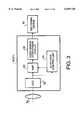
- FIG. 3a block diagram of a CCD camera unit used in the endoscope shown in FIG. 1;
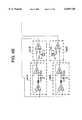
- FIG. 4(which consists of FIGS. 4A and 4B) shows a circuitry of the CCD camera unit shown in FIG. 3;
- FIGS. 5A and 5Bshow wavelength of an output signal of the CCD shown in FIG. 3;
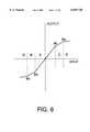
- FIG. 6shows I/O characteristics of an amplifier when gain control is performed
- FIG. 7shows a schematic structure of an endoscope system according to a second embodiment of the invention.
- FIG. 8schematically shows a structure of an image intensifier and a CCD camera unit according to the second embodiment.
- FIG. 9shows a configuration of the image intensifier control circuit shown in FIG. 8.
- FIG. 1shows a structure of an endoscope system 100 according to a first embodiment of the invention.
- the endoscope system 100includes an endoscope 10, a light source unit 20 which emits light for illuminating an object to be observed, and an imaging unit 30 for capturing image of the object.
- a display device 50is connected to the imaging unit 30 via a video switching device 40.
- the endoscope 10has insertion portion 11 having a cylindrical shape, an operation portion 12 which is connected to a proximal end of the insertion portion 11, and a light guide connecting tube 13 which is formed as an extension of the outer surface of the operation portion 12.
- the operation portion 12is provided with an eyepiece unit 12a by which the endoscope 10 and the imaging unit 30 are detatchably connected.
- a connector 13ais provided at a distal end of the light guide connecting tube 13.
- the endoscope 10is detatchably connected to the light source unit 20 by means of the connector 13a.
- an image guide fiber bundle 14is enclosed, in the endoscope 10, from the distal end of the insertion portion 11 to the proximal end of the operation portion 12.
- an objective optical system 15which forms an image of the object on a light receiving end surface of the image guide fiber bundle 14 is accommodated.
- a window 18is formed to introduce light from the object towards the objective optical system 15.
- an eyepiece lens 16is accommodated for observing the image which is guided from the light receiving end surface to a light emerging end surface of the image guide fiber bundle 14. It should be noted that the eyepiece lens 16 is usually used such that an observer can view the image therethrough. However, if the imaging unit 30 is connected as shown in FIG. 1, the eyepiece lens 16 is moved to a position corresponding to 0 (zero) diopter. The light emitted by the object located in front of the distal end of the endoscope 10 is introduced inside the endoscope 10, and converged by the objective optical system 15. The image formed by the objective optical system 15 is transmitted by the image guide fiber bundle 14 towards the eyepiece unit 12a, and then introduced to the imaging unit 30 through the eyepiece lens 16.
- a light guide fiber bundle 17is provided inside the endoscope 10, from the end of the connector 13a to the distal end of the insertion portion 11, a light guide fiber bundle 17 is provided.
- a light receiving surface (i.e., a connector 13a side surface) of the light guide fiber bundle 17faces the light source unit 20 when the connector 13a is connected to the light source unit 20.
- An light emerging surface (i.e., a distal end side surface) of the light guide fiber bundle 17is arranged perpendicular to an optical axis of the objective optical system 17.
- a window 19is formed in front of the light guide fiber bundle 17, on the end surface of the endoscope 10.
- a Xenon lamp 21is provided inside the light source unit 20 inside the light source unit 20, at a position opposing to the light guide fiber bundle 17 when the connector 13a is connected to the light source unit 20.
- the Xenon lamp 21emits light, the light is converged and incident on the light receiving surface of the light guide fiber bundle 17. The light is then transmitted inside the light guide fiber bundle 17 and emerged from the other end of the light guide fiber bundle 17, and emitted outside through the window 19.
- a filter 22 for excitation lightis movably provided such that the filter 22 can be inserted in or retracted from an optical path between the lamp 21 and the light receiving surface of the light guide fiber bundle 17, by means of a solenoid (not shown).
- the filter 22is inserted in the optical path when the fluorescent image is to be observed, and is retracted from the optical path when a normal image is observed.
- the filter 22allows light having a wavelength within a range of 420 nm through 480 nm.
- the organic tissueswhen illuminated with the excitation light having the wavelength of 420 nm through 480 nm, fluoresce and emit light. Normal organic tissues (which do not have disorder) fluoresce and emit light having a wavelength within a range of 500 nm through 570 nm.
- the fluorescent light emitted by the organic tissuespass through the observing window 18, the objective optical system 15, and incident on the light receiving surface of the image guide fiber bundle 14.
- the imaging unit 30accommodates an imaging optical system 30a which constitutes, together with the eyepiece lens 16, a relay optical system.
- a CCD camera 31 for normal observationis disposed at a position where the imaging optical system 30a forms an image.
- another CCD camera 41 for observing fluorescent light imageis disposed next to the CCD camera 31.
- the CCD camera 31 and the CCD camera 41have the same structure.
- the CCD cameras 31 and 41are connected to a switching device 40 which is connected to the display device 50.
- the switching device 40transmits one of the signals output by the CCD camera 31 and CCD camera 41 to the display device 50.
- a mirror 32which is retractably inserted in the optical path between the eyepiece lens 16 and the CCD camera 31 is provided.
- the mirror 32deflects the light emerged from the eyepiece lens 16 when inserted within the optical path.
- the mirror 32is retracted from the optical path as indicated by a solid line in FIG. 1.
- the optical axis of the eyepiece lens 16intersects the reflection surface of the mirror 32 at 45 degrees as indicated by broken lines in FIG. 1 such that light emerged from the eyepiece lens 16 is deflected at 90 degrees.
- a dichroic mirror 33is provided on the optical axis of the eyepiece lens 16 deflected by the mirror 32 such that the optical axis intersects the reflection surface of the dichroic mirror 33 at 45 degrees.
- the dichroic mirror 33reflect light having a wavelength within a range of 500 nm through 570 nm, and allows the other light to pass through.
- an imaging optical system 33aOn the optical path of the light reflected by the dichroic mirror 33, an imaging optical system 33a is provided, and at a position where an image is formed by the imaging optical system 33a, an image intensifier 34 for amplifying an intensity of light reflected by the dichroic mirror 33 is provided. It should be noted that an optical path length between the eyepiece lens 16 and the CCD camera 31 and an optical path length between the eyepiece lens 16 and the image intensifier 34 are the same.
- FIG. 2schematically shows a structure of the image intensifier 34.
- the image intensifier 34includes a first fiber plate 35 having a photo-electrical surface 35a, a micro channel plate (MCP) 36, and a second fiber plate 37 which has a fluorescent surface 37a.
- MCPmicro channel plate
- the first fiber plate 35divides the formed image into pixels and transmits the pixels, and transmits the light to the photo-electrical surface 35a.
- the photo-electric surface 35athus converts the optical image into an electronic image.
- electrodesare connected to which a predetermined voltage is applied.
- the electronic image converted by the photo-electric surface 35ais amplified when passes through the MCP 36, and is projected on the fluorescent surface 37a at which the electronic image is converted into an optical image.
- the converted optical imageis transmitted to an opposite side surface of the second fiber plate 37.
- the fluorescent object image amplified by the image intensifier 34is relayed by the imaging optical system 39 provided on the light emerging surface side of the image intensifier 34, and is incident on the CCD camera 41 for observing the fluorescent image.
- FIG. 3is a block diagram illustrating the CCD camera 41.
- the CCD camera 41includes a CCD (Charge Coupled Device) 51, an amplifier 53 for amplifying an output signal of the CCD 51, an automatic gain controller (AGC) 54 which controls a gain of the amplifier 53, and a video signal conversion circuit 55 for converting the output signal of the amplifier 53 into a video signal.
- CCDCharge Coupled Device
- AGCautomatic gain controller
- CCD 51is an area sensor for receiving the image output from the light emerging surface of the image guide fiber bundle 14.
- the CCD 51is arranged such that the light receiving surface of the CCD 51 is substantially perpendicular to the optical axis of the imaging optical system 39.
- the output signal of the CCD 51is input to the amplifier 53 and the AGC 54.
- the amplifier 53amplifies the signal output by the CCD 51 at a certain gain, the transmits the amplified signal to the video signal conversion circuit 55.
- the gain of the amplifier 53is variable, and is controlled by the AGC 54.
- the AGC 54controls the gain of the amplifier 53 based on the amplitude of the CCD 51 so that the output signal of the amplifier 53 has a value within a predetermined range. That is, if the amplitude of the signal supplied from the CCD 51 to the AGC 54 is greater than a predetermined reference value (e.g., if a distance between the distal end of the endoscope 10 and the object to be observed is shorter than an appropriate distance, or intensity of excitation light illuminating the object is larger than an appropriate amount), the AGC 54 lowers the gain of the amplifier 53.
- a predetermined reference valuee.g., if a distance between the distal end of the endoscope 10 and the object to be observed is shorter than an appropriate distance, or intensity of excitation light illuminating the object is larger than an appropriate amount
- the AGC 54increases the gain of the amplifier 53 if the amplitude of the signal supplied from the CCD 51 to the AGC 54 is less than the predetermined reference value (e.g., if a distance between the distal end of the endoscope 10 and the object to be observed is greater than the appropriate distance, or intensity of excitation light illuminating the object is less than the appropriate amount), the AGC 54 increases the gain of the amplifier 53.
- the predetermined reference valuee.g., if a distance between the distal end of the endoscope 10 and the object to be observed is greater than the appropriate distance, or intensity of excitation light illuminating the object is less than the appropriate amount
- the video signal conversation circuit 55receives the output signal of the amplifier 53 and converts the received signal into the video signal (e.g., an NTSC signal), and transmits the converted signal to the switching device 40.
- the video signale.g., an NTSC signal
- FIGS. 4A and 4Bshows a circuitry of the CCD camera 41.
- An output terminal of the CCD 41is connected, through a resistor R10 to an inverting input terminal of the operational amplifier U1B.
- a non-inverting input terminal of the operational amplifier U1Bis connected, through a resistor R14 and a variable resistor R17, to a voltage source Vcc.
- a feed back resistor R9connects the output terminal and the inverting input terminal of the operational amplifier U1B.
- the output terminal of the operation amplifier U1Bis connected with a condenser C1 for preventing a DC component from being transmitted.
- the other end of the condenser C1is connected to a resistor R16 for discharging the condenser C1.
- the end of the condenser C1 at which the resistor R16 is connected,is also connected, through a resister R11, to the inverting input terminal of an operational amplifier U2B.
- the non-inverting input terminal of the operational amplifier U2Bis connected to an end of a resistor R15, the other end of which is grounded.
- a feed back resistor R7connects the output terminal and the inverting input terminal of the operational amplifier U2B.
- the output of the operational amplifier U2Bis input to the video signal conversion circuit 55.
- FIG. 5AAn example of change of the output voltage of the CCD 51 (i.e., a voltage applied to the inverting input terminal of the operational amplifier U1B) is shown in FIG. 5A.
- the output voltageis lowered, with respect to a predetermined voltage, i.e., Vcc, in accordance with amount of light received by the CCD 51.
- the output voltage of the CCD 51is inverted and amplified by the operational amplifier U1B, and output thereby.
- the output voltage of the operational amplifier U1Bis applied, through the condenser C1, at a point X in FIG. 4A, and an example thereof, which corresponds to the output voltage of the CCD 51 shown in FIG. 5A is indicated in FIG. 5B.
- the voltage at the point Xis inverted and amplified by the operational amplifier U2B, the output voltage of which is applied to the video signal conversation circuit 55.
- an output value control circuit 54Awhich is indicated by one-dotted lines in FIG. 4A, functions to substantially lower the gain of the operational amplifier U2B.
- the output value control circuit 54Ais described in detail hereinafter.
- the point Xis connected to the inverting input terminal of the operational amplifier U1A.
- the inverting input terminal of the operational amplifier U1Ais also connected with a resistor R2 and a variable resistor R1 which is connected to a constant voltage source.
- the non-inverting input terminal of the operational amplifier U1Ais connected to a resistor R8 the other end of which is grounded.
- a diode D1is connected between the output terminal and the inverting input terminal of the operational amplifier U1A.
- a diode D2is connected to the output terminal of the operational amplifier U1A.
- a diode D2, a resistor R5, and a resistor R6are connected in series. The end of the resistor R6 is connected to resistor R7 and the inverting input terminal of the operational amplifier U2B.
- the resistor R2is connected to the inverting input terminal of the operational amplifier U1A, an end of the resistor R3 is connected, the other end of the resistor R3 is connected to the diode D2 and a source of an FET Q1.
- a gate of the FET Q1is connected to the output terminal of a comparator 541B.
- the source of the FET Q1is connected to a connecting point Y1 of the resistor R5 and the diode D2, and a drain of the FET Q1 is connected to the other end of the resistor R5. It should be noted that the FET Q1 is turned On or OFF by the comparator 541B which will be described in detail.
- the output voltage of the output voltage control circuit 54Ais 0 (zero) volt when the voltage output by the operational amplifier U1B is negative.
- a negative reference voltage VR2is applied to the resistor R2. Therefore, if the absolute value of the voltage (a positive voltage Vin at the point X) applied to the resistor R2 is smaller than the negative reference voltage VR2, the diode D1 is forward-biased and the diode D2 is reverse-biased, and accordingly the operational amplifier U1A does not amplify the input voltage. If the absolute value of the positive voltage Vin is greater than the absolute value of the negative reference voltage VR2, the diode D1 is reverse-biased, and accordingly an electrical current flows across the resistors R3 and R4.
- the operational amplifier U1Ainvert-amplifies the input voltage applied to the inverting input terminal at a predetermined gain. It should be noted that, by changing the value of the variable resistor R1 to change the voltage VR2, the characteristic of the output value control circuit 54A can be changed.
- an output value control circuit 54Bwhich is indicated by two-dotted lines in FIG. 4A, functions to substantially lower the gain of the operational amplifier U2B.
- the output value control circuit 54Bis now described in detail hereinafter.
- the point Xis connected to the inverting input terminal of the operational amplifier U2A through a resister R12.
- the inverting input terminal of the operational amplifier U2Ais also connected with a resistor R18 and a variable resistor R21 which is connected to a positive constant voltage source.
- the non-inverting input terminal of the operational amplifier U2Ais connected to a resistor R22 the other end of which is grounded.
- a diode D3is connected between the output terminal and the inverting input terminal of the operational amplifier U2A.
- a diode D4is connected to the output terminal of the operational amplifier U2A.
- the end of the resistor R20is connected to resistor R7 and the inverting input terminal of the operational amplifier U2B.
- an end of the resistor R13is connected, the other end of the resistor R13 is connected to the diode D4 and a source of an FET Q2.
- a gate of the FET Q2is connected to the output terminal of a comparator 542B.
- the source of the FET Q2is connected to a connecting point Y2 of the resistor R19 and the diode D4, and a drain of the FET Q2 is connected to the other end of the resistor R19. It should be noted that the FET Q2 is turned ON or OFF by the comparator 542B which will be described in detail.
- the output voltage of the output voltage control circuit 54Bis 0 (zero) V when the voltage output by the operational amplifier U1B is positive.
- a positive reference voltage VR18is applied to the resistor R18. Therefore, if the voltage Vin at the point X is negative and the absolute value of the voltage Vin is smaller than the positive reference voltage VR18, the diode D3 is forward-biased and the diode D4 is reverse-biased, and accordingly the operational amplifier U2A does not amplify the input voltage. If the absolute value of the negative voltage Vin is greater than the absolute value of the positive reference voltage VR18, the diode D3 is reverse-biased, and accordingly an electrical current flows across the resistors R18 and R13.
- the operational amplifier U2Ainvert-amplifies the input voltage applied to the inverting input terminal at a predetermined gain. It should be noted that, by changing the value of the variable resistor R21 to change the voltage VR18, the characteristic of the output value control circuit 54B can be changed.
- a voltage Vc at the output terminal C of the operational amplifier U2Bis expressed as follows.
- voltage Vc1represents an output voltage of the operational amplifier U2B based only on the output voltage of the operational amplifier U1A, and is expressed as follows:
- Vy1is a voltage at the point Y1.
- voltage Vc2is an output voltage of the operational amplifier U2B based only on the output voltage of the operational amplifier U1B, and is expressed as follows:
- voltage Vc3is an output voltage of the operational amplifier U2B based only on the output voltage of the operational amplifier U2A, and is expressed as follows:
- Vy2is a voltage at the point Y2.
- the operational amplifier U1Avaries a negative electrical current ⁇ (indicated in FIG. 4A) so that the voltage applied to the inverting input terminal of the operational amplifier U2B to vary.
- the operational amplifier U2Avaries a positive electrical current ⁇ (indicated in FIG. 4A) so that the voltage applied to the inverting input terminal of the operational amplifier U2B to vary.
- the AGC 54further includes, as shown in FIG. 4B, a first peak hold circuit 541A, the first comparator 541B, a second peak hold circuit 542A, and the second comparator 542B.
- the first peak hold circuit 541Aholds the positive peak value of the voltage Vx of the point X.
- the first comparator 541Bcompares the positive peak value of the point X with a predetermined positive reference voltage, and if the positive peak value of the point X exceeds a second positive reference voltage, the first comparator 541B turns on the FET Q1. Then, the resistor R5 is short-circuited. That is, R5 can be removed from equation (2), and therefore, the voltage Vc1 in equation (1) will be expressed as follows.
- the second peak hold circuit 542Aholds the negative peak value of the voltage Vx of the point X.
- the second comparator 542Bcompares the negative peak value of the point X with a second negative reference voltage, and if the negative peak value of the point X becomes less than the negative reference voltage, the second comparator 542B turns on the FET Q2. Then, the resistor R19 is short-circuited. That is, R19 can be removed from equation (4), and the voltage Vc3 is expressed as follows.
- the output voltage Vcis equal to Vc2 since voltage Vc1 and Vc2 are both zero. If the voltage Vx exceeds the range defined by the first negative reference voltage and the first positive reference voltage, but greater than the second negative reference voltage or less than the second positive reference voltage described above, the output voltage Vc is expressed by equation (1), and at this stage voltages Vc1, Vc2 and Vc3 are respectively expressed by equations (2), (3) and (4).
- the output voltage Vcis expressed by equation (1), and in this case, voltage Vc1, Vc2 and Vc3 are expressed by equations (5), (3) and (6), respectively. Therefore, the gain of the amplifier 53 varies in accordance with the voltage Vx which changes proportional to the change of the output voltage of the CCD 51.
- the period of time during which the peak hold circuit 541A holds the peak value of voltage Vxcorresponds to time constants determined by the resistor R25 and the condenser C2.
- the period of time during which the peak hold circuit 542A holds the peak value of voltage Vxcorresponds to time constants determined by the resistor R29 and the condenser C3.
- both of the time constantsare set to 1/30 seconds, which corresponds to one image frame period. The time constants can be changed by changing values of the resistors and condensers.
- reference voltages for each of the circuits 53, 53b, 541B, and 542Bcan be changed. Accordingly, the characteristics of the gain of the amplifier 53 as shown in FIG. 6 can be arbitrarily set.
- FIG. 6shows an example of an I/O (Input/Output) characteristic of the amplifier 53 when the gain thereof is controlled by the AGC 54.
- the CCD 51outputs voltage which varies either a negative or a positive side with respect to zero volt.
- the gain of the amplifier 53is relatively great, while when the input voltage is out of the range A, and in a range B or C (i.e., when the absolute value of the input voltage is relatively great), the gain of the amplifier 53 is lowered.
- the gain of the amplifier 53is much lower.
- the input voltage at which the output voltage control circuit 54A starts to operate(which is represented by point M1 in FIG. 6) can be changed.
- the output voltage control circuit 54Bby changing the voltage VR18, the input voltage at which the output voltage control circuit 54B starts to operate (which is represented by point M2 in FIG. 6) can be changed.
- the first comparator 541Bby changing the reference voltage applied to the non-inverting terminal of the operational amplifier U4A, the peak value of the voltage Vin at which the FET Q1 is switched between ON and OFF (which is represented by point M3 in FIG. 6) can be changed.
- the peak value of the voltage Vin at which the FET Q2 is switched between ON and OFF(which is represented by point M4 in FIG. 6) can be changed.
- the insertion portion 11 of the endoscope 10is inserted in a human cavity, and the distal end of the insertion portion 11 is located closely adjacent to an object to be observed.
- the filter 22is retracted from the optical path, and the mirror 32 is also retracted from the optical path.
- the lamp 21emits a white light, which is directed through the light guide fiber bundle 17 and the window 19, and is projected on the object, i.e., the organic tissues.
- the organic tissuesreflect the light which is incident, through the window 18, on the objective optical system 15.
- the objective optical system 15converges the reflected light to form an image which is guided through the image guide fiber bundle 14 and the eyepiece lens 16 and directed to the imaging unit 30.
- an image of the objectis formed on the light receiving surface of the CCD camera 31.
- the CCD camera 31captures the image, and outputs a video signal which is transmitted to the display device 50 through the switching device 40.
- the filter 22 and the mirror 32are inserted in the optical paths.
- the white light emitted by the lamp 21passes through the filter 22, and accordingly only the excitation light is transmitted by the light guide fiber bundle 13 and emitted to the object through the window 19.
- the objecti.e., the organic tissues
- the fluorescent light emitted by the organic tissuesis directed through the window 18, to the objective optical system 15 and converged thereby.
- the lightis then directed, by the image guide fiber bundle 14, to the imaging unit 30 through the eyepiece lens 16.
- the fluorescent light emerged from the eyepiece lens 16is reflected by the mirror 32, and a part of the light having a wavelength within a range of 500 nm through 570 nm is reflected by the dichroic mirror 33.
- the fluorescent imageis formed on the image receiving surface of the image intensifier 34.
- the image intensifier 34amplifies the intensity of light forming the fluorescent image, which is incident on the CCD camera 41 through the imaging optical system.
- the image signalis transmitted from the CCD 51 of the CCD camera 41 to the amplifier 53 and the AGC 54.
- the AGC 54controls the gain of the amplifier 53 in accordance with the characteristic shown in FIG. 6. Therefore, if the distance between the distal end of the insertion portion 11 and the object is closer to an appropriate distance and/or if the amount of the excitation light projected to the object is greater than an appropriate amount, the gain of the amplifier 53 is controlled to lower. On the other hand, if the distance between the distal end of the insertion portion 11 and the object is further to an appropriate distance and/or if the amount of the excitation light projected to the object is less than an appropriate amount, the gain of the amplifier 53 is controlled to increase.
- the fluorescent image signal thus processedis converted in to the video signal (e.g., the NTSC signal) by the video signal conversion circuit 55, and supplied to the switching device 40.
- the switching device 40then transmits the video signals received from the CCD camera 41 to the display device 50 for displaying the fluorescent image (image formed by the fluorescent light).
- an observercan observe the fluorescent image displayed by the display device 50, and determines whether the objective organic tissues have a disorder.
- FIG. 7shows a schematic structure of an endoscope system according to a second embodiment.
- the difference between the first and second embodimentis that, the CCD camera 41 of the first embodiment is replaced with a CCD camera 71, and further a driver 75 is added in the second embodiment.
- the other portions of the endoscope system shown in FIG. 7are the same as those of the endoscope system shown in FIG. 1.
- the CCD camera 71includes a CCD 151 which is similar to the CCD 51 of the first embodiment, an image intensifier control circuit 72, and a video signal conversion circuit 155 which is similar to the video signal conversion circuit 55.
- the image intensifier control circuithas a function as an amplifier.
- the image intensifier control circuit 72controls the driver 75 to vary the voltage applied to the electrodes of the MCP 36 in accordance with the output signal of the CCD 151.
- FIG. 9shows a configuration of the image intensifier control circuit 72 shown in FIG. 8.
- An amplifieramplifies the output signal of the CCD 151.
- the DC component of the signal output by the inverting amplifier 152is removed by a condenser C1.
- the output signal of the amplifier 152is applied to another amplifier 153.
- the amplifier 153amplifies the signal transmitted through the condenser C1.
- a peak hold circuit 160is connected.
- the peak hold circuit 160holds a positive peak value at the point X and output the same.
- the output value of the peak hold circuit 160is applied to a differential amplifier 73.
- a reference peak voltage Vrp applied to a non-inverting input terminal of an operational amplifier U4Ahas been adjusted such that the voltage Vrp equals to a peak voltage Vp at the point X when the distance between the object and the distal end of the endoscope 10 is appropriate, and the amount of light projected to the object is also appropriate.
- the output of the differential amplifier 73is zero.
- the differential amplifier 73determines the time constant of the peak hold circuit 160. In this embodiment, the time constant corresponds to a period during which the CCD 151 outputs the signal for one frame.
- the A/D converter 74converts the output voltage of the differential amplifier 73 into a digital value, which is transmitted to the driver 75.
- the driver 75applies a voltage to the electrodes for the MCP 36 in accordance with the data transmitted from the A/D converter 74. Specifically, if the digital data represents the positive voltage, the driver increases the voltage applied to the MCP 36, and if the digital data represents the negative voltage, the driver decreases the voltage applied to the MCP 36. If the digital data represents zero, the driver holds the currently applying voltage.
- an appropriate image of the fluorescing objectcan be obtained, and further, the size of the imaging unit can be made compact.
- the observercan determine the organic tissues having a disorder accurately.
Landscapes
- Health & Medical Sciences (AREA)
- Life Sciences & Earth Sciences (AREA)
- Surgery (AREA)
- Engineering & Computer Science (AREA)
- Molecular Biology (AREA)
- Heart & Thoracic Surgery (AREA)
- Biophysics (AREA)
- Veterinary Medicine (AREA)
- Public Health (AREA)
- Pathology (AREA)
- General Health & Medical Sciences (AREA)
- Animal Behavior & Ethology (AREA)
- Biomedical Technology (AREA)
- Physics & Mathematics (AREA)
- Medical Informatics (AREA)
- Radiology & Medical Imaging (AREA)
- Optics & Photonics (AREA)
- Nuclear Medicine, Radiotherapy & Molecular Imaging (AREA)
- Multimedia (AREA)
- Signal Processing (AREA)
- Endoscopes (AREA)
Abstract
Description
Vc=-(Vc1+Vc2+Vc3) (1)
Vc1=-Vy1×(R7/R5+R6)) (2),
Vc2=-Vx×(R7/R11) (3),
Vc3=-Vy2×(R7/R19+R20)) (4),
Vc1=-Vy1×(R7/R6) (5)
Vc3=-Vy2×(R7/R20) (6)
Claims (5)
Applications Claiming Priority (2)
| Application Number | Priority Date | Filing Date | Title |
|---|---|---|---|
| JP9-053622 | 1997-03-07 | ||
| JP5362297 | 1997-03-07 |
Publications (1)
| Publication Number | Publication Date |
|---|---|
| US6059720Atrue US6059720A (en) | 2000-05-09 |
Family
ID=12948018
Family Applications (1)
| Application Number | Title | Priority Date | Filing Date |
|---|---|---|---|
| US09/035,337Expired - LifetimeUS6059720A (en) | 1997-03-07 | 1998-03-05 | Endoscope system with amplification of fluorescent image |
Country Status (2)
| Country | Link |
|---|---|
| US (1) | US6059720A (en) |
| DE (1) | DE19809727C2 (en) |
Cited By (53)
| Publication number | Priority date | Publication date | Assignee | Title |
|---|---|---|---|---|
| US6462770B1 (en)* | 1998-04-20 | 2002-10-08 | Xillix Technologies Corp. | Imaging system with automatic gain control for reflectance and fluorescence endoscopy |
| US20020177780A1 (en)* | 2001-05-07 | 2002-11-28 | Fuji Photo Film Co., Ltd. | Fluorescence image display apparatus |
| US20030202630A1 (en)* | 1999-03-22 | 2003-10-30 | Syncrotronics Corp. | Precision endoscopic imaging system |
| US6821245B2 (en) | 2000-07-14 | 2004-11-23 | Xillix Technologies Corporation | Compact fluorescence endoscopy video system |
| US6899675B2 (en) | 2002-01-15 | 2005-05-31 | Xillix Technologies Corp. | Fluorescence endoscopy video systems with no moving parts in the camera |
| US6902527B1 (en)* | 1999-05-18 | 2005-06-07 | Olympus Corporation | Endoscope system with charge multiplying imaging device and automatic gain control |
| US20050170332A1 (en)* | 2004-02-02 | 2005-08-04 | Atsuyoshi Shimamoto | Measuring method and measuring device |
| EP1574162A3 (en)* | 2004-03-08 | 2005-10-05 | Fraunhofer-Gesellschaft zur Förderung der angewandten Forschung e.V. | Imaging device with multiple imaging modes |
| US20050283048A1 (en)* | 2001-10-19 | 2005-12-22 | Visionscope, Llc | Portable imaging system employing a miniature endoscope |
| US20060241496A1 (en)* | 2002-01-15 | 2006-10-26 | Xillix Technologies Corp. | Filter for use with imaging endoscopes |
| US20070090985A1 (en)* | 2005-10-06 | 2007-04-26 | Carl Zeiss Surgical Gmbh | Microscopy system and recording method for visualizing fluorescence |
| US20070167681A1 (en)* | 2001-10-19 | 2007-07-19 | Gill Thomas J | Portable imaging system employing a miniature endoscope |
| US20080064925A1 (en)* | 2001-10-19 | 2008-03-13 | Gill Thomas J | Portable imaging system employing a miniature endoscope |
| US20080073163A1 (en)* | 2006-09-22 | 2008-03-27 | Weir Michael P | Micro-electromechanical device |
| US20080167521A1 (en)* | 2007-01-09 | 2008-07-10 | Sheetz Jane A | Method of in vivo monitoring using an imaging system including scanned beam imaging unit |
| US20080177140A1 (en)* | 2007-01-23 | 2008-07-24 | Xillix Technologies Corp. | Cameras for fluorescence and reflectance imaging |
| US20080226034A1 (en)* | 2007-03-12 | 2008-09-18 | Weir Michael P | Power modulation of a scanning beam for imaging, therapy, and/or diagnosis |
| US20080242967A1 (en)* | 2007-03-27 | 2008-10-02 | Ethicon Endo-Surgery, Inc. | Medical imaging and therapy utilizing a scanned beam system operating at multiple wavelengths |
| US20080252778A1 (en)* | 2007-04-13 | 2008-10-16 | Ethicon Endo-Surgery, Inc. | Combined SBI and conventional image processor |
| US20080255458A1 (en)* | 2007-04-13 | 2008-10-16 | Ethicon Endo-Surgery, Inc. | System and method using fluorescence to examine within a patient's anatomy |
| US20080275305A1 (en)* | 2007-05-01 | 2008-11-06 | Ethicon Endo-Surgery, Inc. | Medical scanned beam imager and components associated therewith |
| US20080312490A1 (en)* | 2007-06-18 | 2008-12-18 | Ethicon Endo-Surgery, Inc. | Methods and devices for repairing damaged or diseased tissue using a scanning beam assembly |
| US20090062659A1 (en)* | 2007-08-28 | 2009-03-05 | Weir Michael P | Medical device including scanned beam unit with operational control features |
| US20090062658A1 (en)* | 2007-08-27 | 2009-03-05 | Dunki-Jacobs Robert J | Position tracking and control for a scanning assembly |
| US20090060381A1 (en)* | 2007-08-31 | 2009-03-05 | Ethicon Endo-Surgery, Inc. | Dynamic range and amplitude control for imaging |
| US7558455B2 (en) | 2007-06-29 | 2009-07-07 | Ethicon Endo-Surgery, Inc | Receiver aperture broadening for scanned beam imaging |
| US7561317B2 (en) | 2006-11-03 | 2009-07-14 | Ethicon Endo-Surgery, Inc. | Resonant Fourier scanning |
| US7589316B2 (en)* | 2007-01-18 | 2009-09-15 | Ethicon Endo-Surgery, Inc. | Scanning beam imaging with adjustable detector sensitivity or gain |
| US7713265B2 (en) | 2006-12-22 | 2010-05-11 | Ethicon Endo-Surgery, Inc. | Apparatus and method for medically treating a tattoo |
| US7942814B2 (en) | 2001-10-19 | 2011-05-17 | Visionscope Technologies Llc | Miniature endoscope with imaging fiber system |
| US7982776B2 (en) | 2007-07-13 | 2011-07-19 | Ethicon Endo-Surgery, Inc. | SBI motion artifact removal apparatus and method |
| US20110213252A1 (en)* | 1999-01-26 | 2011-09-01 | Fulghum Stephen F | Autofluorescence imaging system for endoscopy |
| US8050520B2 (en) | 2008-03-27 | 2011-11-01 | Ethicon Endo-Surgery, Inc. | Method for creating a pixel image from sampled data of a scanned beam imager |
| US8273015B2 (en) | 2007-01-09 | 2012-09-25 | Ethicon Endo-Surgery, Inc. | Methods for imaging the anatomy with an anatomically secured scanner assembly |
| US8317689B1 (en) | 1999-09-13 | 2012-11-27 | Visionscope Technologies Llc | Miniature endoscope system |
| US8332014B2 (en) | 2008-04-25 | 2012-12-11 | Ethicon Endo-Surgery, Inc. | Scanned beam device and method using same which measures the reflectance of patient tissue |
| US20150018690A1 (en)* | 2013-07-12 | 2015-01-15 | Korea Electrotechnology Research Institute | Apparatus and method for detecting nir fluorescence at sentinel lymph node |
| US9125552B2 (en) | 2007-07-31 | 2015-09-08 | Ethicon Endo-Surgery, Inc. | Optical scanning module and means for attaching the module to medical instruments for introducing the module into the anatomy |
| US9386909B2 (en) | 2006-07-28 | 2016-07-12 | Novadaq Technologies Inc. | System and method for deposition and removal of an optical element on an endoscope objective |
| US9420202B1 (en)* | 2015-04-01 | 2016-08-16 | Aviation Specialties Unlimited, Inc. | Compact intensified camera module |
| US9642532B2 (en) | 2008-03-18 | 2017-05-09 | Novadaq Technologies Inc. | Imaging system for combined full-color reflectance and near-infrared imaging |
| US9814378B2 (en) | 2011-03-08 | 2017-11-14 | Novadaq Technologies Inc. | Full spectrum LED illuminator having a mechanical enclosure and heatsink |
| US9877654B2 (en) | 2006-02-07 | 2018-01-30 | Novadaq Technologies Inc. | Near infrared imaging |
| US10165972B2 (en) | 2013-07-12 | 2019-01-01 | Inthesmart Co., Ltd. | Apparatus and method for detecting NIR fluorescence at sentinel lymph node |
| US20190089920A1 (en)* | 2016-05-30 | 2019-03-21 | Olympus Corporation | Endoscope apparatus and endoscope |
| EP3469978A1 (en) | 2017-10-03 | 2019-04-17 | Visionsense LTD | Fluorescent imaging device with a distance sensor and with means for determining a limited gain based on a distance and an associated method and a computer program product |
| US10293122B2 (en) | 2016-03-17 | 2019-05-21 | Novadaq Technologies ULC | Endoluminal introducer with contamination avoidance |
| US10694151B2 (en) | 2006-12-22 | 2020-06-23 | Novadaq Technologies ULC | Imaging system with a single color image sensor for simultaneous fluorescence and color video endoscopy |
| US10869645B2 (en) | 2016-06-14 | 2020-12-22 | Stryker European Operations Limited | Methods and systems for adaptive imaging for low light signal enhancement in medical visualization |
| USD916294S1 (en) | 2016-04-28 | 2021-04-13 | Stryker European Operations Limited | Illumination and imaging device |
| US10980420B2 (en) | 2016-01-26 | 2021-04-20 | Stryker European Operations Limited | Configurable platform |
| US10992848B2 (en) | 2017-02-10 | 2021-04-27 | Novadaq Technologies ULC | Open-field handheld fluorescence imaging systems and methods |
| US11930278B2 (en) | 2015-11-13 | 2024-03-12 | Stryker Corporation | Systems and methods for illumination and imaging of a target |
Families Citing this family (1)
| Publication number | Priority date | Publication date | Assignee | Title |
|---|---|---|---|---|
| CN107518879A (en)* | 2017-10-11 | 2017-12-29 | 北京数字精准医疗科技有限公司 | A kind of fluoroscopic imaging device and method |
Citations (13)
| Publication number | Priority date | Publication date | Assignee | Title |
|---|---|---|---|---|
| US4791480A (en)* | 1986-09-29 | 1988-12-13 | Kabushiki Kaisha Toshiba | Endoscopic system with adjustable light source |
| US4951135A (en)* | 1988-01-11 | 1990-08-21 | Olympus Optical Co., Ltd. | Electronic-type endoscope system having capability of setting AGC variation region |
| US4967269A (en)* | 1988-07-28 | 1990-10-30 | Olympus Optical Co., Ltd. | Endoscope automatic light control apparatus and endoscope apparatus making use of the same |
| US5078150A (en)* | 1988-05-02 | 1992-01-07 | Olympus Optical Co., Ltd. | Spectral diagnosing apparatus with endoscope |
| US5162913A (en)* | 1990-02-26 | 1992-11-10 | Medical Concepts, Inc. | Apparatus for modulating the output of a ccd camera |
| JPH0654792A (en)* | 1991-05-08 | 1994-03-01 | Xillix Technol Corp | Image pickup device |
| JPH0777580A (en)* | 1993-09-09 | 1995-03-20 | Toshiba Corp | Collimator for solid state detector |
| JPH07155292A (en)* | 1993-12-03 | 1995-06-20 | Olympus Optical Co Ltd | Fluorescence observing apparatus |
| JPH07204156A (en)* | 1993-12-03 | 1995-08-08 | Olympus Optical Co Ltd | Fluorescence observation device |
| US5452723A (en)* | 1992-07-24 | 1995-09-26 | Massachusetts Institute Of Technology | Calibrated spectrographic imaging |
| JPH08224210A (en)* | 1995-02-23 | 1996-09-03 | Olympus Optical Co Ltd | Fluorescence observing device |
| US5701903A (en)* | 1994-06-23 | 1997-12-30 | Asahi Kogaku Kogyo Kabushiki Kaisha | Fluoroscopic apparatus |
| US5749830A (en)* | 1993-12-03 | 1998-05-12 | Olympus Optical Co., Ltd. | Fluorescent endoscope apparatus |
Family Cites Families (3)
| Publication number | Priority date | Publication date | Assignee | Title |
|---|---|---|---|---|
| JP2655568B2 (en)* | 1984-08-31 | 1997-09-24 | オリンパス光学工業株式会社 | Endoscope using solid-state imaging device |
| JP3411737B2 (en)* | 1995-03-03 | 2003-06-03 | ペンタックス株式会社 | Biological fluorescence diagnostic equipment |
| US5840017A (en)* | 1995-08-03 | 1998-11-24 | Asahi Kogaku Kogyo Kabushiki Kaisha | Endoscope system |
- 1998
- 1998-03-05USUS09/035,337patent/US6059720A/ennot_activeExpired - Lifetime
- 1998-03-06DEDE19809727Apatent/DE19809727C2/ennot_activeExpired - Lifetime
Patent Citations (14)
| Publication number | Priority date | Publication date | Assignee | Title |
|---|---|---|---|---|
| US4791480A (en)* | 1986-09-29 | 1988-12-13 | Kabushiki Kaisha Toshiba | Endoscopic system with adjustable light source |
| US4951135A (en)* | 1988-01-11 | 1990-08-21 | Olympus Optical Co., Ltd. | Electronic-type endoscope system having capability of setting AGC variation region |
| US5078150A (en)* | 1988-05-02 | 1992-01-07 | Olympus Optical Co., Ltd. | Spectral diagnosing apparatus with endoscope |
| US4967269A (en)* | 1988-07-28 | 1990-10-30 | Olympus Optical Co., Ltd. | Endoscope automatic light control apparatus and endoscope apparatus making use of the same |
| US5162913A (en)* | 1990-02-26 | 1992-11-10 | Medical Concepts, Inc. | Apparatus for modulating the output of a ccd camera |
| JPH0654792A (en)* | 1991-05-08 | 1994-03-01 | Xillix Technol Corp | Image pickup device |
| US5507287A (en)* | 1991-05-08 | 1996-04-16 | Xillix Technologies Corporation | Endoscopic imaging system for diseased tissue |
| US5452723A (en)* | 1992-07-24 | 1995-09-26 | Massachusetts Institute Of Technology | Calibrated spectrographic imaging |
| JPH0777580A (en)* | 1993-09-09 | 1995-03-20 | Toshiba Corp | Collimator for solid state detector |
| JPH07204156A (en)* | 1993-12-03 | 1995-08-08 | Olympus Optical Co Ltd | Fluorescence observation device |
| JPH07155292A (en)* | 1993-12-03 | 1995-06-20 | Olympus Optical Co Ltd | Fluorescence observing apparatus |
| US5749830A (en)* | 1993-12-03 | 1998-05-12 | Olympus Optical Co., Ltd. | Fluorescent endoscope apparatus |
| US5701903A (en)* | 1994-06-23 | 1997-12-30 | Asahi Kogaku Kogyo Kabushiki Kaisha | Fluoroscopic apparatus |
| JPH08224210A (en)* | 1995-02-23 | 1996-09-03 | Olympus Optical Co Ltd | Fluorescence observing device |
Cited By (98)
| Publication number | Priority date | Publication date | Assignee | Title |
|---|---|---|---|---|
| US6462770B1 (en)* | 1998-04-20 | 2002-10-08 | Xillix Technologies Corp. | Imaging system with automatic gain control for reflectance and fluorescence endoscopy |
| US20110213252A1 (en)* | 1999-01-26 | 2011-09-01 | Fulghum Stephen F | Autofluorescence imaging system for endoscopy |
| US8764643B2 (en)* | 1999-01-26 | 2014-07-01 | Hoya Corporation | Autofluorescence imaging system for endoscopy |
| US7035372B2 (en)* | 1999-03-22 | 2006-04-25 | Synchrotronics, Co. | Precision endoscopic imaging system |
| US20030202630A1 (en)* | 1999-03-22 | 2003-10-30 | Syncrotronics Corp. | Precision endoscopic imaging system |
| US6902527B1 (en)* | 1999-05-18 | 2005-06-07 | Olympus Corporation | Endoscope system with charge multiplying imaging device and automatic gain control |
| US8317689B1 (en) | 1999-09-13 | 2012-11-27 | Visionscope Technologies Llc | Miniature endoscope system |
| US20100198010A1 (en)* | 2000-07-14 | 2010-08-05 | Novadaq Technologies Inc. | Compact fluorescence endoscopy video system |
| US20050065406A1 (en)* | 2000-07-14 | 2005-03-24 | Xillix Technologies Corporation | Compact fluorescence endoscopy video system |
| US20100210904A1 (en)* | 2000-07-14 | 2010-08-19 | Novadaq Technologies Inc. | Compact fluorescence endoscopy video system |
| US7341557B2 (en) | 2000-07-14 | 2008-03-11 | Novadaq Technologies Inc. | Compact fluorescence endoscopy video system |
| US7722534B2 (en) | 2000-07-14 | 2010-05-25 | Novadaq Technologies, Inc. | Compact fluorescence endoscopy video system |
| US6821245B2 (en) | 2000-07-14 | 2004-11-23 | Xillix Technologies Corporation | Compact fluorescence endoscopy video system |
| US8961403B2 (en) | 2000-07-14 | 2015-02-24 | Novadaq Technologies Inc. | Compact fluorescence endoscopy video system |
| US9968244B2 (en) | 2000-07-14 | 2018-05-15 | Novadaq Technologies ULC | Compact fluorescence endoscopy video system |
| US20060058684A1 (en)* | 2001-05-07 | 2006-03-16 | Fuji Photo Film Co., Ltd. | Fluorescence image display apparatus |
| EP1256310A3 (en)* | 2001-05-07 | 2003-09-03 | Fuji Photo Film Co., Ltd. | Fluorescence image display apparatus |
| US7043291B2 (en) | 2001-05-07 | 2006-05-09 | Fuji Photo Film Co., Ltd. | Fluorescence image display apparatus |
| US7583993B2 (en) | 2001-05-07 | 2009-09-01 | Fujifilm Corporation | Fluorescence image display apparatus |
| US20020177780A1 (en)* | 2001-05-07 | 2002-11-28 | Fuji Photo Film Co., Ltd. | Fluorescence image display apparatus |
| US20050283048A1 (en)* | 2001-10-19 | 2005-12-22 | Visionscope, Llc | Portable imaging system employing a miniature endoscope |
| US20080064925A1 (en)* | 2001-10-19 | 2008-03-13 | Gill Thomas J | Portable imaging system employing a miniature endoscope |
| US7942814B2 (en) | 2001-10-19 | 2011-05-17 | Visionscope Technologies Llc | Miniature endoscope with imaging fiber system |
| US10595710B2 (en) | 2001-10-19 | 2020-03-24 | Visionscope Technologies Llc | Portable imaging system employing a miniature endoscope |
| US20070167681A1 (en)* | 2001-10-19 | 2007-07-19 | Gill Thomas J | Portable imaging system employing a miniature endoscope |
| US8038602B2 (en) | 2001-10-19 | 2011-10-18 | Visionscope Llc | Portable imaging system employing a miniature endoscope |
| US11484189B2 (en) | 2001-10-19 | 2022-11-01 | Visionscope Technologies Llc | Portable imaging system employing a miniature endoscope |
| US10182709B2 (en) | 2002-01-15 | 2019-01-22 | Novadaq Technologies ULC | Filter for use with imaging endoscopes |
| US6899675B2 (en) | 2002-01-15 | 2005-05-31 | Xillix Technologies Corp. | Fluorescence endoscopy video systems with no moving parts in the camera |
| US20050143627A1 (en)* | 2002-01-15 | 2005-06-30 | Xillix Technologies Corporation | Fluorescence endoscopy video systems with no moving parts in the camera |
| US20060241496A1 (en)* | 2002-01-15 | 2006-10-26 | Xillix Technologies Corp. | Filter for use with imaging endoscopes |
| US20050170332A1 (en)* | 2004-02-02 | 2005-08-04 | Atsuyoshi Shimamoto | Measuring method and measuring device |
| EP1574162A3 (en)* | 2004-03-08 | 2005-10-05 | Fraunhofer-Gesellschaft zur Förderung der angewandten Forschung e.V. | Imaging device with multiple imaging modes |
| US20050219376A1 (en)* | 2004-03-08 | 2005-10-06 | Fraunhofer-Gesellschaft Zur Foerderung Der Angewandten Forschung E.V. | Image recording device having several image recording modes |
| US20070015963A1 (en)* | 2005-05-04 | 2007-01-18 | Xillix Technologies Corp. | Filter for use with imaging endoscopes |
| US8630698B2 (en) | 2005-05-04 | 2014-01-14 | Novadaq Technologies, Inc. | Filter for use with imaging endoscopes |
| US20070090985A1 (en)* | 2005-10-06 | 2007-04-26 | Carl Zeiss Surgical Gmbh | Microscopy system and recording method for visualizing fluorescence |
| US7369073B2 (en) | 2005-10-06 | 2008-05-06 | Carl Zeiss Surgical Gmbh | Microscopy system and recording method for visualizing fluorescence |
| US9877654B2 (en) | 2006-02-07 | 2018-01-30 | Novadaq Technologies Inc. | Near infrared imaging |
| US9386909B2 (en) | 2006-07-28 | 2016-07-12 | Novadaq Technologies Inc. | System and method for deposition and removal of an optical element on an endoscope objective |
| US9079762B2 (en) | 2006-09-22 | 2015-07-14 | Ethicon Endo-Surgery, Inc. | Micro-electromechanical device |
| US20080073163A1 (en)* | 2006-09-22 | 2008-03-27 | Weir Michael P | Micro-electromechanical device |
| US7561317B2 (en) | 2006-11-03 | 2009-07-14 | Ethicon Endo-Surgery, Inc. | Resonant Fourier scanning |
| US11025867B2 (en) | 2006-12-22 | 2021-06-01 | Stryker European Operations Limited | Imaging systems and methods for displaying fluorescence and visible images |
| US7713265B2 (en) | 2006-12-22 | 2010-05-11 | Ethicon Endo-Surgery, Inc. | Apparatus and method for medically treating a tattoo |
| US10694151B2 (en) | 2006-12-22 | 2020-06-23 | Novadaq Technologies ULC | Imaging system with a single color image sensor for simultaneous fluorescence and color video endoscopy |
| US10694152B2 (en) | 2006-12-22 | 2020-06-23 | Novadaq Technologies ULC | Imaging systems and methods for displaying fluorescence and visible images |
| US11770503B2 (en) | 2006-12-22 | 2023-09-26 | Stryker European Operations Limited | Imaging systems and methods for displaying fluorescence and visible images |
| US20080167521A1 (en)* | 2007-01-09 | 2008-07-10 | Sheetz Jane A | Method of in vivo monitoring using an imaging system including scanned beam imaging unit |
| US8273015B2 (en) | 2007-01-09 | 2012-09-25 | Ethicon Endo-Surgery, Inc. | Methods for imaging the anatomy with an anatomically secured scanner assembly |
| US8801606B2 (en) | 2007-01-09 | 2014-08-12 | Ethicon Endo-Surgery, Inc. | Method of in vivo monitoring using an imaging system including scanned beam imaging unit |
| US7589316B2 (en)* | 2007-01-18 | 2009-09-15 | Ethicon Endo-Surgery, Inc. | Scanning beam imaging with adjustable detector sensitivity or gain |
| US20080177140A1 (en)* | 2007-01-23 | 2008-07-24 | Xillix Technologies Corp. | Cameras for fluorescence and reflectance imaging |
| US8216214B2 (en) | 2007-03-12 | 2012-07-10 | Ethicon Endo-Surgery, Inc. | Power modulation of a scanning beam for imaging, therapy, and/or diagnosis |
| US20080226034A1 (en)* | 2007-03-12 | 2008-09-18 | Weir Michael P | Power modulation of a scanning beam for imaging, therapy, and/or diagnosis |
| US20080242967A1 (en)* | 2007-03-27 | 2008-10-02 | Ethicon Endo-Surgery, Inc. | Medical imaging and therapy utilizing a scanned beam system operating at multiple wavelengths |
| US7995045B2 (en) | 2007-04-13 | 2011-08-09 | Ethicon Endo-Surgery, Inc. | Combined SBI and conventional image processor |
| US8626271B2 (en) | 2007-04-13 | 2014-01-07 | Ethicon Endo-Surgery, Inc. | System and method using fluorescence to examine within a patient's anatomy |
| US20080255458A1 (en)* | 2007-04-13 | 2008-10-16 | Ethicon Endo-Surgery, Inc. | System and method using fluorescence to examine within a patient's anatomy |
| US20080252778A1 (en)* | 2007-04-13 | 2008-10-16 | Ethicon Endo-Surgery, Inc. | Combined SBI and conventional image processor |
| US20080275305A1 (en)* | 2007-05-01 | 2008-11-06 | Ethicon Endo-Surgery, Inc. | Medical scanned beam imager and components associated therewith |
| US20080312490A1 (en)* | 2007-06-18 | 2008-12-18 | Ethicon Endo-Surgery, Inc. | Methods and devices for repairing damaged or diseased tissue using a scanning beam assembly |
| US8160678B2 (en) | 2007-06-18 | 2012-04-17 | Ethicon Endo-Surgery, Inc. | Methods and devices for repairing damaged or diseased tissue using a scanning beam assembly |
| US7558455B2 (en) | 2007-06-29 | 2009-07-07 | Ethicon Endo-Surgery, Inc | Receiver aperture broadening for scanned beam imaging |
| US7982776B2 (en) | 2007-07-13 | 2011-07-19 | Ethicon Endo-Surgery, Inc. | SBI motion artifact removal apparatus and method |
| US9125552B2 (en) | 2007-07-31 | 2015-09-08 | Ethicon Endo-Surgery, Inc. | Optical scanning module and means for attaching the module to medical instruments for introducing the module into the anatomy |
| US7983739B2 (en) | 2007-08-27 | 2011-07-19 | Ethicon Endo-Surgery, Inc. | Position tracking and control for a scanning assembly |
| US20090062658A1 (en)* | 2007-08-27 | 2009-03-05 | Dunki-Jacobs Robert J | Position tracking and control for a scanning assembly |
| US7925333B2 (en) | 2007-08-28 | 2011-04-12 | Ethicon Endo-Surgery, Inc. | Medical device including scanned beam unit with operational control features |
| US20090062659A1 (en)* | 2007-08-28 | 2009-03-05 | Weir Michael P | Medical device including scanned beam unit with operational control features |
| US20090060381A1 (en)* | 2007-08-31 | 2009-03-05 | Ethicon Endo-Surgery, Inc. | Dynamic range and amplitude control for imaging |
| US9642532B2 (en) | 2008-03-18 | 2017-05-09 | Novadaq Technologies Inc. | Imaging system for combined full-color reflectance and near-infrared imaging |
| US10779734B2 (en) | 2008-03-18 | 2020-09-22 | Stryker European Operations Limited | Imaging system for combine full-color reflectance and near-infrared imaging |
| US8050520B2 (en) | 2008-03-27 | 2011-11-01 | Ethicon Endo-Surgery, Inc. | Method for creating a pixel image from sampled data of a scanned beam imager |
| US8332014B2 (en) | 2008-04-25 | 2012-12-11 | Ethicon Endo-Surgery, Inc. | Scanned beam device and method using same which measures the reflectance of patient tissue |
| US9814378B2 (en) | 2011-03-08 | 2017-11-14 | Novadaq Technologies Inc. | Full spectrum LED illuminator having a mechanical enclosure and heatsink |
| US10165972B2 (en) | 2013-07-12 | 2019-01-01 | Inthesmart Co., Ltd. | Apparatus and method for detecting NIR fluorescence at sentinel lymph node |
| US20150018690A1 (en)* | 2013-07-12 | 2015-01-15 | Korea Electrotechnology Research Institute | Apparatus and method for detecting nir fluorescence at sentinel lymph node |
| US10111614B2 (en) | 2013-07-12 | 2018-10-30 | Inthesmart Co. Ltd. | Apparatus and method for detecting NIR fluorescence at sentinel lymph node |
| US9795338B2 (en)* | 2013-07-12 | 2017-10-24 | Inthesmart Co. Ltd. | Apparatus and method for detecting NIR fluorescence at sentinel lymph node |
| WO2016160754A1 (en)* | 2015-04-01 | 2016-10-06 | Aviation Specialties Unlimited, Inc. | Compact intensified camera module |
| US9420202B1 (en)* | 2015-04-01 | 2016-08-16 | Aviation Specialties Unlimited, Inc. | Compact intensified camera module |
| US11930278B2 (en) | 2015-11-13 | 2024-03-12 | Stryker Corporation | Systems and methods for illumination and imaging of a target |
| US11298024B2 (en) | 2016-01-26 | 2022-04-12 | Stryker European Operations Limited | Configurable platform |
| US10980420B2 (en) | 2016-01-26 | 2021-04-20 | Stryker European Operations Limited | Configurable platform |
| US10293122B2 (en) | 2016-03-17 | 2019-05-21 | Novadaq Technologies ULC | Endoluminal introducer with contamination avoidance |
| USD977480S1 (en) | 2016-04-28 | 2023-02-07 | Stryker European Operations Limited | Device for illumination and imaging of a target |
| USD916294S1 (en) | 2016-04-28 | 2021-04-13 | Stryker European Operations Limited | Illumination and imaging device |
| USD1065550S1 (en) | 2016-04-28 | 2025-03-04 | Stryker Corporation | Device for illumination and imaging of a target |
| US10868992B2 (en)* | 2016-05-30 | 2020-12-15 | Olympus Corporation | Endoscope apparatus and endoscope |
| US20190089920A1 (en)* | 2016-05-30 | 2019-03-21 | Olympus Corporation | Endoscope apparatus and endoscope |
| US10869645B2 (en) | 2016-06-14 | 2020-12-22 | Stryker European Operations Limited | Methods and systems for adaptive imaging for low light signal enhancement in medical visualization |
| US11756674B2 (en) | 2016-06-14 | 2023-09-12 | Stryker European Operations Limited | Methods and systems for adaptive imaging for low light signal enhancement in medical visualization |
| US10992848B2 (en) | 2017-02-10 | 2021-04-27 | Novadaq Technologies ULC | Open-field handheld fluorescence imaging systems and methods |
| US11140305B2 (en) | 2017-02-10 | 2021-10-05 | Stryker European Operations Limited | Open-field handheld fluorescence imaging systems and methods |
| US12028600B2 (en) | 2017-02-10 | 2024-07-02 | Stryker Corporation | Open-field handheld fluorescence imaging systems and methods |
| US11363954B2 (en)* | 2017-10-03 | 2022-06-21 | Visionsense Ltd. | Fluorescent imager with limited variable gain |
| EP3469978A1 (en) | 2017-10-03 | 2019-04-17 | Visionsense LTD | Fluorescent imaging device with a distance sensor and with means for determining a limited gain based on a distance and an associated method and a computer program product |
Also Published As
| Publication number | Publication date |
|---|---|
| DE19809727A1 (en) | 1998-09-10 |
| DE19809727C2 (en) | 2001-11-22 |
Similar Documents
| Publication | Publication Date | Title |
|---|---|---|
| US6059720A (en) | Endoscope system with amplification of fluorescent image | |
| US10609351B2 (en) | Endoscope and endoscopic system | |
| CN101686798B (en) | Endoscope device and setting method thereof | |
| JPS63294826A (en) | Endoscopic apparatus | |
| US5078150A (en) | Spectral diagnosing apparatus with endoscope | |
| JP4772235B2 (en) | Endoscope device | |
| EP2368488A1 (en) | Endoscope system comprising calibration means and calibration method thereof | |
| US20100097454A1 (en) | Endoscope apparatus and control method therefor | |
| EP2368485A2 (en) | Electronic endoscope system | |
| JP5714875B2 (en) | Fluorescence endoscope device | |
| JP2007020880A (en) | Endoscope | |
| JP2003339636A (en) | Automatic adjustment device for amplification of electronic endoscope | |
| JPS6148333A (en) | Endoscope photographing apparatus | |
| US5570129A (en) | Method and apparatus for correcting the white balance of a video color picture signal | |
| US4872029A (en) | Automatic adjusted light switching circuit | |
| JP2641653B2 (en) | Endoscope device | |
| JPH07246185A (en) | Imaging device creating visible and infrared images | |
| JP4578608B2 (en) | Endoscope system | |
| JP3140548B2 (en) | Endoscope image brightness control device | |
| JP4300915B2 (en) | Microscope image processing system and image processing apparatus | |
| JPH0852114A (en) | Ophthalmological apparatus for image pickup | |
| JP2956915B2 (en) | Surface-sequential electronic endoscope device | |
| JP3423052B2 (en) | Microscope imaging system | |
| JP3288414B2 (en) | Electronic endoscope device | |
| JPH01213615A (en) | Electronic endoscope device |
Legal Events
| Date | Code | Title | Description |
|---|---|---|---|
| AS | Assignment | Owner name:ASAHI KOGAKU KOGYO KABUSHIKI KAISHA, JAPAN Free format text:ASSIGNMENT OF ASSIGNORS INTEREST;ASSIGNORS:FURUSAWA, KOICHI;KANEKO, ATSUMI;REEL/FRAME:009023/0549 Effective date:19980305 | |
| STCF | Information on status: patent grant | Free format text:PATENTED CASE | |
| FEPP | Fee payment procedure | Free format text:PAYOR NUMBER ASSIGNED (ORIGINAL EVENT CODE: ASPN); ENTITY STATUS OF PATENT OWNER: LARGE ENTITY | |
| FPAY | Fee payment | Year of fee payment:4 | |
| FPAY | Fee payment | Year of fee payment:8 | |
| FPAY | Fee payment | Year of fee payment:12 | |
| AS | Assignment | Owner name:PENTAX CORPORATION, JAPAN Free format text:CHANGE OF NAME;ASSIGNOR:ASAHI KOGAKU KOGYO KABUSHIKI KAISHA;REEL/FRAME:041758/0285 Effective date:20021001 | |
| AS | Assignment | Owner name:HOYA CORPORATION, JAPAN Free format text:MERGER;ASSIGNOR:PENTAX CORPORATION;REEL/FRAME:042114/0463 Effective date:20080407 | |
| AS | Assignment | Owner name:HOYA CORPORATION, JAPAN Free format text:CHANGE OF ADDRESS OF ASSIGNEE;ASSIGNOR:HOYA CORPORATION;REEL/FRAME:042424/0318 Effective date:20160401 |