US6059370A - Wheelchair seat back pelvic support system - Google Patents
Wheelchair seat back pelvic support systemDownload PDFInfo
- Publication number
- US6059370A US6059370AUS09/156,156US15615698AUS6059370AUS 6059370 AUS6059370 AUS 6059370AUS 15615698 AUS15615698 AUS 15615698AUS 6059370 AUS6059370 AUS 6059370A
- Authority
- US
- United States
- Prior art keywords
- support system
- fastening element
- pelvis
- layer
- wheelchair
- Prior art date
- Legal status (The legal status is an assumption and is not a legal conclusion. Google has not performed a legal analysis and makes no representation as to the accuracy of the status listed.)
- Expired - Fee Related
Links
Images


Classifications
- A—HUMAN NECESSITIES
- A61—MEDICAL OR VETERINARY SCIENCE; HYGIENE
- A61G—TRANSPORT, PERSONAL CONVEYANCES, OR ACCOMMODATION SPECIALLY ADAPTED FOR PATIENTS OR DISABLED PERSONS; OPERATING TABLES OR CHAIRS; CHAIRS FOR DENTISTRY; FUNERAL DEVICES
- A61G5/00—Chairs or personal conveyances specially adapted for patients or disabled persons, e.g. wheelchairs
- A61G5/10—Parts, details or accessories
- A61G5/1054—Large wheels, e.g. higher than the seat portion
- A—HUMAN NECESSITIES
- A61—MEDICAL OR VETERINARY SCIENCE; HYGIENE
- A61G—TRANSPORT, PERSONAL CONVEYANCES, OR ACCOMMODATION SPECIALLY ADAPTED FOR PATIENTS OR DISABLED PERSONS; OPERATING TABLES OR CHAIRS; CHAIRS FOR DENTISTRY; FUNERAL DEVICES
- A61G5/00—Chairs or personal conveyances specially adapted for patients or disabled persons, e.g. wheelchairs
- A61G5/10—Parts, details or accessories
- A61G5/1091—Cushions, seats or abduction devices
- A—HUMAN NECESSITIES
- A61—MEDICAL OR VETERINARY SCIENCE; HYGIENE
- A61G—TRANSPORT, PERSONAL CONVEYANCES, OR ACCOMMODATION SPECIALLY ADAPTED FOR PATIENTS OR DISABLED PERSONS; OPERATING TABLES OR CHAIRS; CHAIRS FOR DENTISTRY; FUNERAL DEVICES
- A61G5/00—Chairs or personal conveyances specially adapted for patients or disabled persons, e.g. wheelchairs
- A61G5/10—Parts, details or accessories
- A61G5/12—Rests specially adapted therefor, e.g. for the head or the feet
- A—HUMAN NECESSITIES
- A61—MEDICAL OR VETERINARY SCIENCE; HYGIENE
- A61G—TRANSPORT, PERSONAL CONVEYANCES, OR ACCOMMODATION SPECIALLY ADAPTED FOR PATIENTS OR DISABLED PERSONS; OPERATING TABLES OR CHAIRS; CHAIRS FOR DENTISTRY; FUNERAL DEVICES
- A61G5/00—Chairs or personal conveyances specially adapted for patients or disabled persons, e.g. wheelchairs
- A61G5/10—Parts, details or accessories
- A61G5/1043—Cushions specially adapted for wheelchairs
Definitions
- This inventionrelates in general to wheelchairs, and in particular to cushioning and support mechanisms suitable for maintaining a wheelchair occupant in proper position. More particularly, this invention pertains to wheelchair cushioning and support mechanisms for enabling a wheelchair to be adjusted to fit the requirements, including the size and shape, of the wheelchair occupant.
- a significant number of people confined to wheelchairshave body deformities that require a customized back support. These wheelchair occupants require a back support that conforms to the shape of their bodies so that they will have enough contact with the back support to be able to sit upright, without falling over.
- a custom shaped back supportalso provides comfort and avoids skin pressure that may result in ducubitus ulcers or other skin problems.
- the backs of the wheelchairare preferably contoured to be able to fit closely to the occupant's body shape to provide support over the occupant's whole back without putting too much pressure on any one point.
- One approach to achieving this goalis to provide a customized foam cushion, formed in place to fit the wheelchair occupant's back.
- Another approachis to carve a foam blank to the shape of the occupant's back.
- Another approach to the problem of properly and easily fitting the foam cushion to meet the needs of the wheelchair occupantis to provide an adjustable hard matrix of metal parts, aligned and adjusted to generally conform to the shape of the occupant's back.
- the hard metal matrixis then covered by foam and a fabric cover.
- a disadvantage of this systemis that several hours of tedious adjustment are required to properly fit the matrix to the shape of the occupant's back.
- a rigid back shellextends between the vertical posts of the wheelchair.
- a padding systemconsisting of a contoured foam pad is attached to the rigid shell, and fluid-filled pads can be used for cushioning sensitive areas of the occupant's back, such as the spinal area.
- U.S. Pat. No. 5,407,248discloses the use of foam blocks removably attached to the seat back by means of hook and loop fasteners, whereby the foam blocks can be removed as needed to form recessed areas generally conforming to the contour of the occupant's back.
- foam transition blockscan be used to smooth out the contour defined by the foam blocks and the recessed areas.
- built-up padscan be applied, using hook and loop fasteners, to the front of the foam blocks, or to the seat back in the recessed areas, to further customize the fit of the wheelchair.
- the support system of U.S. Pat. No. 5,407,248provides numerous advantages to the wheelchair occupant, particularly in the area of comfort for the mid and upper back regions of the occupant's back. It would be advantageous if there could be developed a support system providing even greater support for wheelchair occupants.
- the present inventionis a support system for use with a wheelchair seat back to provide support for the pelvic area of a wheelchair occupant.
- the support systemcomprises a base plate mountable to a wheelchair seat back, and a base layer adhered to the based plate.
- the base plateis dimensioned and configured to substantially span and conform to the wheelchair seat back.
- a front surface of the base layercomprises a fastening element for mounting additional layers, or pelvis-conforming blocks, to the base layer.
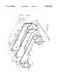
- FIG. 1is a partial schematic view in perspective of a wheelchair having a base plate for a pelvic support system of the invention.
- FIG. 2is an exploded schematic view in perspective of the pelvic support system of the invention and a wheelchair seat back upon which the pelvic support system may attached.
- FIG. 3is a view in elevation of the base plate for the pelvic support system of FIG. 2.
- FIG. 4is a top view of the base plate of FIG. 3.
- FIG. 5is a schematic view in perspective of a wheelchair assembly having a cushion suitable for use with the pelvic support system illustrated in FIGS. 1-4.
- FIG. 6is a schematic cross-sectional view in elevation illustrating the relationship of the pelvic support system of the invention to the pelvis of a wheelchair occupant.
- FIG. 7is a schematic top view of the pelvis of the wheelchair occupant of FIG. 6.
- FIG. 8is a schematic view in perspective of another embodiment of the wheelchair of the invention, with the pelvic support system in an exploded view, where the pelvic support system of the invention is formed without the base plate.
- FIG. 9is a schematic view in perspective of yet another embodiment of the wheelchair of the invention, where the seat back shell is formed without side wings.
- FIG. 10is a top view, similar to the view shown in FIG. 4, of a planar base plate.
- wheelchairis indicated generally at 10.
- the wheelchair 10includes a seat 14 and a seat back 16.
- the frame(not shown) provides a mounting for the seat 14, the seat back 16, caster wheels (not shown) and the rear wheels 18.
- the wheelchair 10can optionally be provided with armrests (not shown) and push handles 20.
- the wheelchair 10is provided with optional side extrusions or side wings 22 suitable for providing lateral support for the upper body of the wheelchair occupant.
- Mounted at the lower end of the seat back 16is the base plate 30 of an adjustable pelvic support system 60 of the invention.
- the base plate 30is formed with two spaced apart angles 12 defining two oppositely disposed support wings 34 and a central base portion 32 between the two spaced apart angles 12 and the two support wings 34.
- the base plate 30is preferably shaped to substantially conform to the wheelchair seat back 16.
- the base plate 30can be attached to the seat back 16 by any suitable means, such as by bolts 36 attaching the support wings 34 to the side wings 22 of the wheelchair 10.
- the side wings 22 of the wheelchair 10preferably have slots or multiple threaded holes 21 (shown in FIG. 2) for receiving the bolts 36 to allow a height adjustment of the base plate 30 for a proper fit with the pelvis of the occupant.
- the side wings 22are provided with a continuous slot or track 37 to allow infinite adjustment of the base plate 30
- the base plate 30 shownincludes a front surface and a back surface.
- the base plate 30is mounted to the lower end of the wheelchair seat back 16 with the back surface of the base plate 30 situated juxtaposed the wheelchair seat back 16.
- the base plate 30is provided with bolt holes 38 for receiving bolts 36 for attaching the support wings 34 to the side wings 22 of the wheelchair 10.
- a base layer 40is attached to the base plate 30.
- the base layer 40has a front surface 31 and a back surface 33 and is shaped to substantially cover the entire front surface 31 of the base plate 30 (shown more clearly in FIG. 4).
- the back surface 33 of the base layer 40is adhered to the front surface of the base plate 30.
- the front surface 31 of the base layer 40comprises a front fastening element (i.e., either a layer of hook fabric or a layer of loop fabric).
- a front fastening elementi.e., either a layer of hook fabric or a layer of loop fabric.
- the base layer 40is a loop fabric, which is adhered to the front surface of the base plate 30, using an adhesive.
- Double sided intermediate and outer hook and loop fabric layers 44 and 46generally conform to the shape of the base plate 30 so that they can be attached and held in place.
- the fabric layers 44 and 46each have a front surface 48 and 50 and a back surface 45 and 47.
- the back surfaces 45 and 47preferably comprise a back fastening element and the front surfaces 48 and 50 preferably comprise a front fastening element.
- the back fastening elementsare preferably a hook portion of a hook and loop-type fastener and the front fastening elements are preferably a loop portion of a hook and loop-type fastener.
- the back hook surface 45 of the intermediate fabric layer 44is matingly engageable with the front loop surface 31 of the base layer fabric 40 and the back hook surface 47 of the outer fabric layer 46 is matingly engageable with the front loop surface 48 of the intermediate fabric layer 44.
- the base layer 40 as well as the intermediate and outer layers 44 and 46are preferably of different thicknesses to allow adjustment of the pelvic support system 60 to accommodate the support needs of the wheelchair occupant.
- intermediate and outer fabric layers 44 and 46are shown, it is to be understood that the requirements of different wheelchair occupants might dictate using anywhere from zero up to four or more fabric layers similar to the layers 44 and 46 to meet the needs of the wheelchair occupant. It can be seen that the use of hook and loop fastening system allows changes in the pelvic support system to be made easily.
- pelvis-conforming blocks 54Secured on the pelvic support system 60 are pelvis-conforming blocks 54, which can take any shape suitable for conforming to the general shape of the pelvis of the occupant.
- the pelvis-conforming blocks 54can be attached to the support wings 34 of the base plate 30, or to the support wings 34a or 34b of the intermediate or outer fabric layers 44 or 46, as shown.
- the pelvis-conforming blocks 54can have the shape of polyhedrons, such as, for example, wedges or pyramids.
- the pelvis-conforming blocks 54can be comprised of foam, and can be covered with a fabric material 55. Other materials can be used also, with the primary function of the blocks 54 being to take up the space so that a shape closely conforming to the pelvis of the wheelchair occupant can be made.
- the pelvis-conforming blocks 54are preferably provided with a hook surface of a hook and loop system 57 so that the blocks 54 can be adhered to the loop surface 50 of the outer fabric layer 46.
- Other methods of attachmentsuch as pressure sensitive adhesive 59, can be used. It should be understood that the invention may be comprised of extra pelvis-conforming blocks 54, if necessary, to conform to the general shape of the pelvis of the occupant.
- a fabric covered foam pad 62can be installed onto the seat back 16 to complete the construction of the seat back 16.
- the pelvis 68 of the occupant 66is generally vertically in line with the pelvic support system 60. Without the proper support provided by the pelvic support system 60, the pelvis 68 of the occupant 66 can pivot forward, in the anterior direction, or rearward in the posterior direction, as indicated by the arrow 70.
- the pelvis-conforming blocks 54are configured or aligned to be slightly above or superior to the pelvis 68 to help provide support for the pelvis. The exact configuration of the blocks 54 will vary from occupant to occupant, and the adaptability of the pelvic support system of the invention provides the flexibility needed to fit any wheelchair occupant.
- FIG. 7illustrates that the pelvis 68 consists in part of the side or iliac portions 72 and the rear or sacral area 74.
- the foam pad 62is not shown.
- the base plate 30 and the fabric layers 44 and 46 (shown in FIG. 2), coupled with the pelvis-conforming blocks 54 (also shown in FIG. 2)wrap around the pelvis and provide the support necessary for maintaining the occupant in the correct orthopedic position in the wheelchair 10 (shown in FIGS. 1 and 5). Without proper support provided by the pelvic support system 60, the pelvis 68 of the occupant can tilt laterally, with one or the other of the iliac portions 72 tilting upward or downward.
- the pelvic support system 80is comprised of fabric layers 82 and 84 similar to the fabric layers 44 and 46 illustrated in FIG. 5.
- fabric layers 82 and 84have loop front surfaces and hook rear surfaces.
- the fabric layer 82is adhered to the wheelchair seat back 16 and side wings 22 in some suitable manner.
- an additional layer of loop fabric(not shown for purposes of clarity), similar to base loop fabric 40, is adhered to the seat back 16 and side wings 22.
- the pelvic support system 80does not have a base plate like the base plate 30 of the pelvic support system 60 described above.
- the pelvic support system of the inventioncan be configured using a base plate 30 on a seat back 90 having no side wings.
- the pelvic support system 60can be built up on the base plate 30 in a manner similar to that described above with reference to FIGS. 1-7.
- FIG. 10illustrates a substantially straight or planar base plate 92 dimensioned to span the wheelchair seat back 16.
- the base platehas a base loop fabric 94 for the attachment of additional fabric layers (not shown) similar to fabric layers 44 and 46 described above.
- additional fabric layersnot shown
- extra pelvis-conforming blocks 54are used to provide adequate support for the pelvis.
Landscapes
- Health & Medical Sciences (AREA)
- Life Sciences & Earth Sciences (AREA)
- Animal Behavior & Ethology (AREA)
- General Health & Medical Sciences (AREA)
- Public Health (AREA)
- Veterinary Medicine (AREA)
- Chair Legs, Seat Parts, And Backrests (AREA)
- Orthopedics, Nursing, And Contraception (AREA)
- Mattresses And Other Support Structures For Chairs And Beds (AREA)
Abstract
Description
Claims (26)
Priority Applications (1)
| Application Number | Priority Date | Filing Date | Title |
|---|---|---|---|
| US09/156,156US6059370A (en) | 1997-09-19 | 1998-09-17 | Wheelchair seat back pelvic support system |
Applications Claiming Priority (2)
| Application Number | Priority Date | Filing Date | Title |
|---|---|---|---|
| US5937797P | 1997-09-19 | 1997-09-19 | |
| US09/156,156US6059370A (en) | 1997-09-19 | 1998-09-17 | Wheelchair seat back pelvic support system |
Publications (1)
| Publication Number | Publication Date |
|---|---|
| US6059370Atrue US6059370A (en) | 2000-05-09 |
Family
ID=22022569
Family Applications (1)
| Application Number | Title | Priority Date | Filing Date |
|---|---|---|---|
| US09/156,156Expired - Fee RelatedUS6059370A (en) | 1997-09-19 | 1998-09-17 | Wheelchair seat back pelvic support system |
Country Status (4)
| Country | Link |
|---|---|
| US (1) | US6059370A (en) |
| EP (1) | EP0904761B1 (en) |
| AT (1) | ATE238747T1 (en) |
| DE (1) | DE69813980T2 (en) |
Cited By (18)
| Publication number | Priority date | Publication date | Assignee | Title |
|---|---|---|---|---|
| US6425635B1 (en)* | 1999-11-01 | 2002-07-30 | Invacare Corporation | Weight-shifting reclining and tilting wheelchair seat |
| US6554365B2 (en)* | 1999-12-23 | 2003-04-29 | Recaro Gmbh & Co. Kg | Modular vehicle seat |
| US6637072B2 (en) | 2000-09-29 | 2003-10-28 | Formway Furniture Limited | Castored base for an office chair |
| US20040104610A1 (en)* | 2002-12-02 | 2004-06-03 | Jan Jaskot | Lumbar support device |
| US6802566B2 (en) | 2000-09-28 | 2004-10-12 | Formway Furniture Limited | Arm assembly for a chair |
| US20040245825A1 (en)* | 2003-06-05 | 2004-12-09 | Battey Robert J. | Seating unit with adjustable lumbar device |
| US6840582B2 (en) | 2002-05-14 | 2005-01-11 | Formway Furniture Limited | Height adjustable arm assembly |
| US20060103204A1 (en)* | 2003-04-03 | 2006-05-18 | Brock M. Walker | Seat with adjustable support system |
| US20070106188A1 (en)* | 2005-10-28 | 2007-05-10 | Walker Brock M | Adjustable seating support system |
| US7347498B2 (en) | 2003-06-03 | 2008-03-25 | Gerard Clifford | Seating device |
| US20100140998A1 (en)* | 2006-10-06 | 2010-06-10 | Brock Walker | Active response seating system |
| US20110001341A1 (en)* | 2009-07-03 | 2011-01-06 | R82 A/S | Adjustable body support |
| US20110148157A1 (en)* | 2009-12-15 | 2011-06-23 | Faurecia Automotive Seating, Inc. | Vehicle seat with pelvis-motion regulator |
| US20120223560A1 (en)* | 2011-03-02 | 2012-09-06 | Hetzel Thomas R | Back Support, Orientation Mechanism and Method |
| US8584286B2 (en) | 2010-04-27 | 2013-11-19 | Ec Service Inc. | Systems and methods for providing a self deflating cushion |
| US10758051B2 (en) | 2017-07-28 | 2020-09-01 | Inter-Face Medical Llc | Lower back and posture support device |
| US11006758B1 (en)* | 2020-01-15 | 2021-05-18 | Merits Health Products Co., Ltd. | Chairback support structure |
| US11957631B2 (en) | 2022-07-13 | 2024-04-16 | Invacare Corporation | Wheelchair and suspension systems |
Families Citing this family (2)
| Publication number | Priority date | Publication date | Assignee | Title |
|---|---|---|---|---|
| CA2473978C (en) | 2002-01-28 | 2009-10-13 | Brock M. Walker | Sacral support member for seating |
| JP7427353B2 (en) | 2015-06-29 | 2024-02-05 | ミラーノル インコーポレイテッド | back support |
Citations (7)
| Publication number | Priority date | Publication date | Assignee | Title |
|---|---|---|---|---|
| CA759358A (en)* | 1967-05-23 | F. Caldemeyer Daniel | Upholstery assembly | |
| US4753482A (en)* | 1986-09-12 | 1988-06-28 | Orthotic & Prosthetic Specialties, Inc. | Customized modular seating system |
| US5131410A (en)* | 1992-02-03 | 1992-07-21 | Neill William R | Adjustable back support for relief of back pain |
| US5149173A (en)* | 1988-11-16 | 1992-09-22 | Jay Medical, Ltd. | Bolster with improved attachment means |
| US5352023A (en)* | 1992-09-16 | 1994-10-04 | Jay Medical, Ltd. | Seating and back systems for a wheelchair |
| US5407248A (en)* | 1991-02-20 | 1995-04-18 | Jay; Eric C. | Deformity back system |
| US5564788A (en)* | 1994-05-19 | 1996-10-15 | Skil-Care Corp. | Thoracic lumbar sacral orthosis support system |
Family Cites Families (5)
| Publication number | Priority date | Publication date | Assignee | Title |
|---|---|---|---|---|
| US4880275A (en)* | 1986-11-10 | 1989-11-14 | Lanteri Michael A | Combination headrest and wall with sliding window |
| US4793652A (en)* | 1987-08-11 | 1988-12-27 | Arbutus Society For Children | Orthopaedic seating device |
| CA2002031C (en)* | 1988-11-16 | 1993-03-23 | Eric C. Jay | Wheelchair back system |
| US5452940A (en)* | 1993-08-04 | 1995-09-26 | Maier; Edmund K. | Pressure relief back cushion |
| CA2131736A1 (en)* | 1994-09-09 | 1996-03-10 | David Quennell | Back support |
- 1998
- 1998-09-17USUS09/156,156patent/US6059370A/ennot_activeExpired - Fee Related
- 1998-09-18EPEP98117787Apatent/EP0904761B1/ennot_activeExpired - Lifetime
- 1998-09-18DEDE69813980Tpatent/DE69813980T2/ennot_activeExpired - Fee Related
- 1998-09-18ATAT98117787Tpatent/ATE238747T1/ennot_activeIP Right Cessation
Patent Citations (8)
| Publication number | Priority date | Publication date | Assignee | Title |
|---|---|---|---|---|
| CA759358A (en)* | 1967-05-23 | F. Caldemeyer Daniel | Upholstery assembly | |
| US4753482A (en)* | 1986-09-12 | 1988-06-28 | Orthotic & Prosthetic Specialties, Inc. | Customized modular seating system |
| US5149173A (en)* | 1988-11-16 | 1992-09-22 | Jay Medical, Ltd. | Bolster with improved attachment means |
| US5407248A (en)* | 1991-02-20 | 1995-04-18 | Jay; Eric C. | Deformity back system |
| US5131410A (en)* | 1992-02-03 | 1992-07-21 | Neill William R | Adjustable back support for relief of back pain |
| US5352023A (en)* | 1992-09-16 | 1994-10-04 | Jay Medical, Ltd. | Seating and back systems for a wheelchair |
| US5647637A (en)* | 1992-09-16 | 1997-07-15 | Jay Medical Ltd. | Seating and back systems for a wheelchair |
| US5564788A (en)* | 1994-05-19 | 1996-10-15 | Skil-Care Corp. | Thoracic lumbar sacral orthosis support system |
Non-Patent Citations (2)
| Title |
|---|
| The Aftermarket Group, Rehab Seating & Positioning Products 1997 1998, p. 23.* |
| The Aftermarket Group, Rehab Seating & Positioning Products 1997-1998, p. 23. |
Cited By (33)
| Publication number | Priority date | Publication date | Assignee | Title |
|---|---|---|---|---|
| US6425635B1 (en)* | 1999-11-01 | 2002-07-30 | Invacare Corporation | Weight-shifting reclining and tilting wheelchair seat |
| US6554365B2 (en)* | 1999-12-23 | 2003-04-29 | Recaro Gmbh & Co. Kg | Modular vehicle seat |
| US7441839B2 (en) | 2000-09-28 | 2008-10-28 | Formway Furniture Limited | Reclinable chair |
| US6802566B2 (en) | 2000-09-28 | 2004-10-12 | Formway Furniture Limited | Arm assembly for a chair |
| US6817667B2 (en) | 2000-09-28 | 2004-11-16 | Formway Furniture Limited | Reclinable chair |
| US6874852B2 (en) | 2000-09-28 | 2005-04-05 | Formway Furniture Limited | Lumbar support |
| US6908159B2 (en) | 2000-09-28 | 2005-06-21 | Formway Furniture Limited | Seat for a reclining office chair |
| US6910741B2 (en) | 2000-09-28 | 2005-06-28 | Formway Furniture Limited | Lumbar support |
| US7798573B2 (en) | 2000-09-28 | 2010-09-21 | Formway Furniture Limited | Reclinable chair |
| US6637072B2 (en) | 2000-09-29 | 2003-10-28 | Formway Furniture Limited | Castored base for an office chair |
| US6840582B2 (en) | 2002-05-14 | 2005-01-11 | Formway Furniture Limited | Height adjustable arm assembly |
| US20040104610A1 (en)* | 2002-12-02 | 2004-06-03 | Jan Jaskot | Lumbar support device |
| US7651163B2 (en)* | 2002-12-02 | 2010-01-26 | Logicback, Inc. | Lumbar support device |
| US20060103204A1 (en)* | 2003-04-03 | 2006-05-18 | Brock M. Walker | Seat with adjustable support system |
| US7429080B2 (en)* | 2003-04-03 | 2008-09-30 | Walker Brock M | Seat with adjustable support system |
| US7347498B2 (en) | 2003-06-03 | 2008-03-25 | Gerard Clifford | Seating device |
| US7097247B2 (en) | 2003-06-05 | 2006-08-29 | Steelcase Development Corporation | Seating unit with adjustable lumbar device |
| US20040245825A1 (en)* | 2003-06-05 | 2004-12-09 | Battey Robert J. | Seating unit with adjustable lumbar device |
| US20070106188A1 (en)* | 2005-10-28 | 2007-05-10 | Walker Brock M | Adjustable seating support system |
| US20100140998A1 (en)* | 2006-10-06 | 2010-06-10 | Brock Walker | Active response seating system |
| US9049937B2 (en) | 2006-10-06 | 2015-06-09 | Brock Walker | Active response seating system |
| US8398170B2 (en) | 2006-10-06 | 2013-03-19 | Brock Walker | Active response seating system |
| US9675179B2 (en) | 2006-10-06 | 2017-06-13 | Trac Tec, Ltd. | Active response seating system |
| US8186756B2 (en)* | 2009-07-03 | 2012-05-29 | R82 A/S | Adjustable body support |
| US20110001341A1 (en)* | 2009-07-03 | 2011-01-06 | R82 A/S | Adjustable body support |
| US20110148157A1 (en)* | 2009-12-15 | 2011-06-23 | Faurecia Automotive Seating, Inc. | Vehicle seat with pelvis-motion regulator |
| US8584286B2 (en) | 2010-04-27 | 2013-11-19 | Ec Service Inc. | Systems and methods for providing a self deflating cushion |
| US20120223560A1 (en)* | 2011-03-02 | 2012-09-06 | Hetzel Thomas R | Back Support, Orientation Mechanism and Method |
| US8567863B2 (en)* | 2011-03-02 | 2013-10-29 | Aspen Seating, Llc | Back support, orientation mechanism and method |
| US10758051B2 (en) | 2017-07-28 | 2020-09-01 | Inter-Face Medical Llc | Lower back and posture support device |
| US11432654B2 (en) | 2017-07-28 | 2022-09-06 | Inter-Face Medical Llc | Lower back and posture support device |
| US11006758B1 (en)* | 2020-01-15 | 2021-05-18 | Merits Health Products Co., Ltd. | Chairback support structure |
| US11957631B2 (en) | 2022-07-13 | 2024-04-16 | Invacare Corporation | Wheelchair and suspension systems |
Also Published As
| Publication number | Publication date |
|---|---|
| EP0904761B1 (en) | 2003-05-02 |
| DE69813980T2 (en) | 2004-05-19 |
| ATE238747T1 (en) | 2003-05-15 |
| EP0904761A1 (en) | 1999-03-31 |
| DE69813980D1 (en) | 2003-06-05 |
Similar Documents
| Publication | Publication Date | Title |
|---|---|---|
| US6059370A (en) | Wheelchair seat back pelvic support system | |
| US4597386A (en) | Lumbar support system | |
| US4753482A (en) | Customized modular seating system | |
| US5593211A (en) | Deformity back system | |
| US6532962B1 (en) | Spinal support system for seating | |
| US5288127A (en) | Rocking seat | |
| US6378947B1 (en) | Seating system | |
| US5758926A (en) | Adjustable seating system | |
| US6095611A (en) | Modular backrest system for a wheelchair | |
| US5647637A (en) | Seating and back systems for a wheelchair | |
| US5228747A (en) | Seating system | |
| US5343876A (en) | Modular pad | |
| US4793652A (en) | Orthopaedic seating device | |
| US5695245A (en) | Orthotic seat | |
| US6033025A (en) | Notched support pads for cushioning wheelchair seatback | |
| CA2131736A1 (en) | Back support | |
| CA2233928C (en) | Flexible contour wheelchair backrest | |
| JPS6128576Y2 (en) | ||
| EP1496770A1 (en) | Backrest or backrest section for a chair, in particular for a wheelchair | |
| GB2323275A (en) | Chair | |
| CA2150902A1 (en) | Adjustable backrest | |
| GB2399744A (en) | Air chair |
Legal Events
| Date | Code | Title | Description |
|---|---|---|---|
| AS | Assignment | Owner name:SUNRISE MEDICAL HHG INC,, COLORADO Free format text:ASSIGNMENT OF ASSIGNORS INTEREST;ASSIGNORS:KANYER, BRIAN D.;CHRISTOFFERSON, JAMES L.;FRERICH, VINCENT J.;AND OTHERS;REEL/FRAME:009631/0650;SIGNING DATES FROM 19981030 TO 19981125 | |
| AS | Assignment | Owner name:BANKERS TRUST COMPANY, NEW YORK Free format text:SECURITY INTEREST;ASSIGNOR:SUNRISE MEDICAL HHG INC.;REEL/FRAME:011506/0787 Effective date:20001213 | |
| FPAY | Fee payment | Year of fee payment:4 | |
| FEPP | Fee payment procedure | Free format text:PAYOR NUMBER ASSIGNED (ORIGINAL EVENT CODE: ASPN); ENTITY STATUS OF PATENT OWNER: LARGE ENTITY | |
| AS | Assignment | Owner name:SUNRISE MEDICAL HHG INC, COLORADO Free format text:PATENT RELEASE;ASSIGNOR:DEUTSCHE BANK TRUST COMPANY AMERICAS;REEL/FRAME:014683/0526 Effective date:20040512 | |
| AS | Assignment | Owner name:DEUTSCHE BANK TRUST COMPANY AMERICAS, NEW YORK Free format text:SECURITY AGREEMENT;ASSIGNOR:SUNRISE MEDICAL HHG INC.;REEL/FRAME:015302/0454 Effective date:20040513 | |
| REMI | Maintenance fee reminder mailed | ||
| LAPS | Lapse for failure to pay maintenance fees | ||
| STCH | Information on status: patent discontinuation | Free format text:PATENT EXPIRED DUE TO NONPAYMENT OF MAINTENANCE FEES UNDER 37 CFR 1.362 | |
| FP | Lapsed due to failure to pay maintenance fee | Effective date:20080509 | |
| AS | Assignment | Owner name:SUNRISE MEDICAL HHG INC., COLORADO Free format text:RELEASE BY SECURED PARTY;ASSIGNOR:DEUTSCHE BANK TRUST COMPANY AMERICAS;REEL/FRAME:035135/0273 Effective date:20121130 |