US6059365A - Orthopedic lounge chair - Google Patents
Orthopedic lounge chairDownload PDFInfo
- Publication number
- US6059365A US6059365AUS09/196,932US19693298AUS6059365AUS 6059365 AUS6059365 AUS 6059365AUS 19693298 AUS19693298 AUS 19693298AUS 6059365 AUS6059365 AUS 6059365A
- Authority
- US
- United States
- Prior art keywords
- support section
- pad
- upper support
- section
- lounge chair
- Prior art date
- Legal status (The legal status is an assumption and is not a legal conclusion. Google has not performed a legal analysis and makes no representation as to the accuracy of the status listed.)
- Expired - Lifetime
Links
Images

Classifications
- A—HUMAN NECESSITIES
- A61—MEDICAL OR VETERINARY SCIENCE; HYGIENE
- A61G—TRANSPORT, PERSONAL CONVEYANCES, OR ACCOMMODATION SPECIALLY ADAPTED FOR PATIENTS OR DISABLED PERSONS; OPERATING TABLES OR CHAIRS; CHAIRS FOR DENTISTRY; FUNERAL DEVICES
- A61G13/00—Operating tables; Auxiliary appliances therefor
- A61G13/10—Parts, details or accessories
- A61G13/105—Portable, foldable or collapsible tables, e.g. for surgery or treatment
- A—HUMAN NECESSITIES
- A47—FURNITURE; DOMESTIC ARTICLES OR APPLIANCES; COFFEE MILLS; SPICE MILLS; SUCTION CLEANERS IN GENERAL
- A47C—CHAIRS; SOFAS; BEDS
- A47C1/00—Chairs adapted for special purposes
- A47C1/02—Reclining or easy chairs
- A47C1/022—Reclining or easy chairs having independently-adjustable supporting parts
- A47C1/024—Reclining or easy chairs having independently-adjustable supporting parts the parts, being the back-rest, or the back-rest and seat unit, having adjustable and lockable inclination
- A47C1/026—Reclining or easy chairs having independently-adjustable supporting parts the parts, being the back-rest, or the back-rest and seat unit, having adjustable and lockable inclination by means of peg-and-notch or pawl-and-ratchet mechanism
- A—HUMAN NECESSITIES
- A47—FURNITURE; DOMESTIC ARTICLES OR APPLIANCES; COFFEE MILLS; SPICE MILLS; SUCTION CLEANERS IN GENERAL
- A47C—CHAIRS; SOFAS; BEDS
- A47C1/00—Chairs adapted for special purposes
- A47C1/14—Beach chairs ; Chairs for outdoor use, e.g. chairs for relaxation or sun-tanning
- A47C1/143—Chaise lounges
- A—HUMAN NECESSITIES
- A47—FURNITURE; DOMESTIC ARTICLES OR APPLIANCES; COFFEE MILLS; SPICE MILLS; SUCTION CLEANERS IN GENERAL
- A47C—CHAIRS; SOFAS; BEDS
- A47C20/00—Head-, foot- or like rests for beds, sofas or the like
- A47C20/04—Head-, foot- or like rests for beds, sofas or the like with adjustable inclination
- A47C20/043—Head-, foot- or like rests for beds, sofas or the like with adjustable inclination by means of peg-and-notch or pawl-and-ratchet mechanism
- Y—GENERAL TAGGING OF NEW TECHNOLOGICAL DEVELOPMENTS; GENERAL TAGGING OF CROSS-SECTIONAL TECHNOLOGIES SPANNING OVER SEVERAL SECTIONS OF THE IPC; TECHNICAL SUBJECTS COVERED BY FORMER USPC CROSS-REFERENCE ART COLLECTIONS [XRACs] AND DIGESTS
- Y10—TECHNICAL SUBJECTS COVERED BY FORMER USPC
- Y10S—TECHNICAL SUBJECTS COVERED BY FORMER USPC CROSS-REFERENCE ART COLLECTIONS [XRACs] AND DIGESTS
- Y10S297/00—Chairs and seats
- Y10S297/90—Chair for suntanning in the prone, i.e. facedown position
Definitions
- the inventionrelates to chairs of a type known as lounge chairs or loungers, where the chair supports the full body length of the user and is foldable so as to be able to support the user in either the seated or prone position.
- this inventionrelates to such chairs which provide an opening situated near the end of the chair adapted to support the user's head so that the user's face can be positioned in the opening when the user is lying face down.
- Lounge chairs for supporting a person in either a prone or seated position and which have body support sections joined in a hinged manner to allow adjustment of the relative angle of adjacent support sectionsare known, and typically consist of a generally horizontal frame supported above a surface by legs, where a fabric or mesh material, in solid sheets or multiple strips, is stretched across the frame.
- the frameis hinged at a point roughly one third of the way from the head supporting end, and also sometimes at a point roughly one third of the way from the feet supporting end, so that the head and/or feet supporting sections can be variably angled relative to the horizontal middle section.
- the hinged sectionsalso allow the chair to be folded into a generally flat and compact configuration for transport or storage.
- a known improvement to the basic lounge chairis the provision of an opening in the head support section of the chair which is configured to receive in a supporting manner the face of a user lying in the face down prone position. This allows the user to relax in the face down position without having to turn the head to either side, and precludes hyper-extension of the neck when reading, since the book can be placed beneath the chair opening. Examples of such a chair is shown in U.S. Pat.
- the lounge chaircomprises a generally rectangular frame member which encompasses the lower body support section and the middle body support section, preferably hinged at the juncture of the two sections so as to allow the sections to be folded into a compact configuration for transport and storage, with leg members depending from the frame member to support the frame in a generally horizontal position a distance above an underlying surface.
- the leg membersare hinged so that they may also be folded into a compact configuration.
- a body support materialsuch as a fabric or mesh, is attached across the frame to support the user.
- a pivotable upper body support sectionalso having a support material attached between its end and lateral members, is pivotally attached to the middle section of the frame member at a point interior to the upper end of the frame, such that an upper end member of the frame extends beneath the upper section, with the upper end member abutting and supporting the upper section when the upper section is fully reclined past horizontal.
- Adjustment support members for the upper sectionwhich interlock with the upper end of the frame member allow the upper section to be positioned at various angles relative to the frame member, from approximately vertical to approximately 15 degrees below horizontal.
- An opening, preferably generally triangular in configuration, sized to receive the face of the user when the user is in the face down prone positionis provided in the upper section.
- a number of removable and position-adjustable pad membersare provided for attachment to the chair, preferably through hook and loop fastening means.
- a generally rectangular abdominal/torso padwhich can also be used under the legs when the user is in the seated position, is removably connected to the upper section at varying positions beneath the face opening.
- a generally elongated rectangular lumbar/breast padis removably connected to the upper section in place of the abdominal/torso pad either transversely for support of the lumbar region in the sitting position or longitudinally to provide support between the breasts for women in the face down prone position.
- a generally U-shaped face pad memberis removably connected to upper section so as to encircle the face opening, where the open end of the face pad is directed toward the lower end for use in a face down prone position and where the open end of the face pad is directed toward the upper end of the upper section for use in a supine or seated position.
- a pair of laterally adjustable shoulder pad membersare connected to the upper section between the face pad and the abdomen/torso pad, where the shoulder pad members can be positioned to the side or underneath the upper section when not in use.
- the abdomen/torso padis approximately three inches thick
- the lumbar/breast padis approximately two to three inches thick
- the lateral segments of the U-shaped face padare approximately two inches thick
- the bridging segmentis approximately one inch thick, such that the combination of the upper section being angled below horizontal and the diminishing thicknesses of the pads produces passive traction in a face down prone user to relieve spinal stresses and provide therapeutic effect to the user.
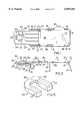
- FIG. 1is a top view of the invention with the pads removed.
- FIG. 2is a top view of the upper section of the invention showing the pads in use.
- FIG. 3is a side view of the invention in the prone position.
- FIG. 4is a side view of the invention in the seating position.
- FIG. 5is a perspective view of the face pad.
- the inventionis a lounge chair of the type which is conformable into multiple supportive positions for a user's body, the chair being of sufficient length to support the entire body, where the chair may be disposed in a relatively horizontal configuration to support the user in a fully prone manner or may be disposed with an end section pivotally raised from horizontal to a generally vertical position to support the user in a seated manner.
- the inventionis a lounge chair 10 comprising a generally rectangular frame member 11 supporting a body support material 21 in a relatively taut manner, the frame member 11 comprising a pair of opposing lateral members 12, a lower end member 13 and an upper end member 14.
- the lower directionshall be taken as the direction toward the portion of the chair 10 which supports the feet of the user, i.e., toward the non-adjustable end
- the upper directionshall be taken as the direction toward the portion of the chair 10 which supports the head of the user, i.e., toward the adjustable end.
- Frame member 11is preferably composed of lightweight, strong tubing, which may be aluminum, PVC or the like, such that the rectangular configuration is relatively rigid and capable of sustaining the body weight of a person.
- the body support material 21is likewise capable of sustaining the weight of a user without excessive deflection, and may be composed of any suitable sheet member, such as a fabric or mesh of natural or synthetic fibers, or alternatively may comprise a large number of strips or tubes aligned in parallel or perpendicular patterns to provide sufficient support to the user.
- the body support material 21may be affixed by any suitable method to the frame member 11, such as by mechanical fasteners or adhesives, or preferably by stitching the material 21 along the edges of the frame member 11, and is attached along both lateral sides 12 and preferably along the lower end member 13.
- the body support material 21does not fully extend to the upper end member 14 of the frame 11, instead covering about two-thirds to three-quarters of the total area of the frame member 10, thereby allowing for connection of the pivoting upper support section 22.
- the frame 11is horizontally supported a distance above an underlying support surface, such as a floor or the ground, by a plural number of leg members 15, which may be composed of any suitably strong and durable material capable of supporting the weight of a user, but are preferably composed of material similar to that composing the frame member 11--metal or plastic tubing.
- the leg members 15are configured with generally wide bases or feet, and most preferably are configured as U-shaped with the ends of the "U" connected to the frame member 11, so that the frame 11 will be suitably supported without sinking when used outdoors on the ground or in the sand.
- leg members 15are connected to the frame member 11 by hinge members 16, such that the legs 15 may be folded against the frame 11 to create a smaller configuration when the chair 10 is being transported or stored.
- Any suitable hinging mechanismmay be used for the leg hinge members 16, but preferably the hinge members 16 having a locking mechanism, such as a depressible pin which interlocks with an aperture to lock the legs 16 in the extended position, so that there is no likelihood of the chair 10 accidentally collapsing during use.
- the leg members 16are preferably of greater length than the legs of standard lounge chairs, preferably of a length to support the frame member 11 approximately eighteen inches above the underlying support surface.
- the frame member 11 and body support material 21together define two segments, a lower support section 17 and a middle support section 18.
- the lower support section 17encompasses the area of the body support material 21 between the lower end member 13 and approximately the lower halves of the lateral members 12.
- the middle support section 18encompasses the area of the body support material 21 between the remaining portions of the lateral members 12.
- the lower support section 17will support the legs of the user and the middle support section 18 will support the buttocks of the user in a seated position or the waist area of a user in the prone position.
- the lateral members 12 of the frame 11are each divided at the midpoint and connected by a frame hinge member 19 attached to a supporting leg member 15, such that the frame member 11 can be folded in half for transport or storage.
- a short segment 20 of the upper sections of each of the lateral frame members 12is angled downward toward the underside of the body support material 21, such that the upper end member 14 is lower than the lower end member 13 when the chair 10 is placed on a level surface.
- the angle between the plane containing the extended, horizontal portions 38 of the lateral members 12 and the plane containing the depending segments 20is sufficient such that, as will be explained in more detail below, the upper support section 22 when abutting the upper end member 14 of the frame 11 will be positioned at an angle below that of the plane containing the horizontal portions 38 of the frame 11, i.e., the plane containing the upper support section 22 will be below horizontal when frame member 11 is positioned horizontally.
- the short segments 20will be at an angle relative to the extended, horizontal portions of the frame member 11 of between approximately 175 and 165 degrees, and most preferably at approximately 172 degrees.
- a frame pad 23comprising a thick tube of expanded polymer foam or similarly compressible material may be positioned on upper end member 14 to provide cushioning under the body support material 21 of the upper support section 22 when it is placed in the lowermost position.
- the upper support section 22is preferably composed of material similar to that of the frame member 11, such as tubular metal or plastic, and is generally rectangular with preferably a U-shaped frame 24 having a pair of opposing lateral members 25 joined by an upper end member 26.
- Lateral members 25may be linear, but are preferably configured with a reduced separation distance toward the upper portion of the upper support section 22 such that the user's arms easily clear the outside of the lateral members 25 when the user is in the face-down prone position and desires the arms to extend below the upper support section 22.
- a body support material of any suitable typeis tautly attached across the area between the lateral members 25 and the upper end member 26.
- the upper support section 22is pivotally attached to the frame member 11 by pivot means 27, which may comprise a pin inserted through apertures in the free ends of each upper section lateral member 25 and each frame lateral member 12. Because of this attachment, the upper support section 22 may be positioned at various angles relative to the frame member 11, from a nearly vertical seating position as shown in FIG. 4 to a prone position as shown in FIG. 3.
- the upper support section 22is fixed in place and supported at the desired position by support member 27, which preferably comprises a generally U-shaped piece of metal or plastic tubing which is pivotally attached near the midpoint of the upper section lateral members 25, the support member 27 further comprising incremental sockets or brackets 28 which receive the upper end member 14 of the frame 11, with the particular set of sockets 28 chosen by the user determining the angle of the upper support section 22 relative to the frame 11.
- support member 27preferably comprises a generally U-shaped piece of metal or plastic tubing which is pivotally attached near the midpoint of the upper section lateral members 25, the support member 27 further comprising incremental sockets or brackets 28 which receive the upper end member 14 of the frame 11, with the particular set of sockets 28 chosen by the user determining the angle of the upper support section 22 relative to the frame 11.
- Other equivalent means for temporarily supporting the upper support section 22 in an angled positionedcould also be utilized.
- the upper support section 22rests directly on the frame upper end member 14, with support member 27 not utilized.
- the frame upper end member 14provides very stable
- the body support material 21 of the upper support section 22is provided with a face opening 29, which may comprise many suitable shapes and as shown is configured with a generally triangular shape, the apex of the triangle being positioned below the base of the triangle. Face opening 29 allows the user, with the chair 10 in the horizontal configuration, to occupy the chair 10 in the face-down prone position with the user's face positioned at the face opening 29. This allows the user to lie face down without having to turn the head to one side, since the user can easily breathe through the face opening 29, as well as read books or magazines placed beneath the chair 10 on the ground or held in the user's arms.
- the body support material 21 of the upper support section 22is provided with pad attachment means 30, preferably the loop component of a hook and loop type fastener, on the lower half of the upper support section 22 below the face opening 29 and extending to the bottom of the upper support section 22.
- the chair 10further comprises a plural number of slightly compressible pad members which comprise supportive filler materials, such as polymer foam or the like, encased in durable covers, which are configured for particular uses and placement on the chair 10.
- One such padis the abdominal/torso pad 31, which is generally rectangular in configuration and is preferably the thickest of all the pad members, being preferably about three inches in thickness, and is approximately equal in width to the width of the frame 11.
- Abdominal/torso pad 31is provided with means to removably affix it to the body support material 21 at a chosen position on the upper support section 22, which may comprise the corresponding hook component of the pad attachment means 30.
- the abdominal/torso pad 31is positioned on the lower half of the upper support section 22 to provide support or positive traction effects when the user is in the prone position, or may be moved to the lower support section 17 to support the legs if desired.
- the second padis the head pad 32, which is designed for use around the face opening 29.
- the head pad 32is generally U-shaped, with a pair of lateral sections 33 joined by a bridging section 34 to define an open central area 35. Lateral sections 33 are preferably curved to provide more comfortable support to the head or face.
- Preferably the bridging section 34is thinner than the lateral sections 33, and most preferably the lateral sections 33 are thinner than the abdominal/torso pad 31, with the bridging section 34 being about one inch thick and the lateral sections 33 being about two inches thick.
- the head pad 32is also provided with means to removably affix it to the body support material 21, which may comprise the corresponding hook components of the pad attachment means 30.
- the head pad 32When the user is in the prone position, the head pad 32 is affixed around the face opening 29 with the thin bridging section 34 at the uppermost position. When the user is in the seated position, the head pad 32 is reversed so that the thin bridging section 35 is lower than the face opening 29.
- the third padis the lumbar/breast pad 39, which is a generally elongated rectangular pad approximately two to three inches thick and long, with a width equal to the width of the frame 11.
- the lumbar/breast pad 39is provided with means to removably affix it to the body support material 21 at a chosen position on the upper support section 22, which may comprise the corresponding hook component of the pad attachment means 30.
- the lumbar/breast pad 39is used in place of the abdominal/torso pad 31 for certain situations, and is positioned transversely across the lower half of the upper support section 22 to provide support or positive traction effects to the lumbar region of the user when in the seated position, or is positioned longitudinally to provide support between the breasts when the user is in the prone position.
- Another set of pad members which may be included on the chair 10are a pair of shoulder pads 36, which may be configured as rectangular pads, preferably of thickness equal to that of the lateral sections 35 of the head pad 32.
- the shoulder pads 36are also attached to the chair 10 in are movable or movable manner, and preferably are attached by inserting an encircling strap member 37 through the shoulder pads 36, with the strap 37 wrapped around the lateral members 25 of the upper support frame 24 just below the face opening 29. This allows the shoulder pads 36 to be moved laterally and longitudinally, as well as allowing the shoulder pads 36 to be slipped to the sides or behind the upper support section 22 if they are not required for support.
- the chair 10is especially suited for use by those with back and neck problems, such as where turning the head to either side is difficult or where pressure relief to the spinal disks is desirable.
- the combination of the head pad 32 and abdominal/torso pad 31, especially when the upper support section 22 is fully reclined to be below horizontal, and in particular the combination resulting from the diminishing thicknesses of the pads 32 and 31 as described,provides a means to deliver passive traction to the user.
- the thick abdominal/torso pad 31can be placed at any location along the spinal column from neck to lower back so as to act as a fulcrum to relieve pressure on that area of the spine.
- the reduction in thickness of the head pad 32 from the lateral sections 33 to the bridging section 34best conforms to the facial skeletal structure and provides the proper head angle relative to the spine when the user is in the face-down prone position or, when inverted, in the seated position, to reduce or eliminate cervical hyper-extension.
Landscapes
- Health & Medical Sciences (AREA)
- General Health & Medical Sciences (AREA)
- Dentistry (AREA)
- Engineering & Computer Science (AREA)
- Biomedical Technology (AREA)
- Life Sciences & Earth Sciences (AREA)
- Animal Behavior & Ethology (AREA)
- Public Health (AREA)
- Veterinary Medicine (AREA)
- Nursing (AREA)
- Special Chairs (AREA)
Abstract
Description
Claims (17)
Priority Applications (1)
| Application Number | Priority Date | Filing Date | Title |
|---|---|---|---|
| US09/196,932US6059365A (en) | 1997-11-28 | 1998-11-20 | Orthopedic lounge chair |
Applications Claiming Priority (2)
| Application Number | Priority Date | Filing Date | Title |
|---|---|---|---|
| US6686197P | 1997-11-28 | 1997-11-28 | |
| US09/196,932US6059365A (en) | 1997-11-28 | 1998-11-20 | Orthopedic lounge chair |
Publications (1)
| Publication Number | Publication Date |
|---|---|
| US6059365Atrue US6059365A (en) | 2000-05-09 |
Family
ID=26747235
Family Applications (1)
| Application Number | Title | Priority Date | Filing Date |
|---|---|---|---|
| US09/196,932Expired - LifetimeUS6059365A (en) | 1997-11-28 | 1998-11-20 | Orthopedic lounge chair |
Country Status (1)
| Country | Link |
|---|---|
| US (1) | US6059365A (en) |
Cited By (31)
| Publication number | Priority date | Publication date | Assignee | Title |
|---|---|---|---|---|
| US6295668B1 (en)* | 1999-08-09 | 2001-10-02 | Shannon I. Nation | Maternity beach chair |
| WO2002058601A1 (en)* | 2001-01-03 | 2002-08-01 | Isis Innovation Limited | Device for assisting in the relocation of dislocated shoulders |
| US6588034B2 (en) | 1999-08-09 | 2003-07-08 | Shannon I. Nation | Maternity beach chair |
| USD486028S1 (en) | 2001-11-20 | 2004-02-03 | Gwen Cathey | Hairstyle protection pillow |
| US6755463B2 (en) | 2002-03-04 | 2004-06-29 | Gaetano Lardieri | Portable reflexology chair |
| US20040183354A1 (en)* | 2003-03-17 | 2004-09-23 | Rodriguez Peter M. | Adjustable lounge chair |
| US6860567B1 (en)* | 2003-03-14 | 2005-03-01 | Bo Bauer | Poolside lounge chair |
| USD517334S1 (en) | 2005-04-15 | 2006-03-21 | Jones Thomas K | Fabric portion of a lounge chair having a face opening in the foot support end |
| US7025421B1 (en)* | 2003-07-28 | 2006-04-11 | Fowler Richard L | Worker's recliner |
| USD527554S1 (en) | 2005-04-15 | 2006-09-05 | Jones Thomas K | Fabric portion of a lounge chair having a face opening in the foot support end |
| US20060224097A1 (en)* | 2005-04-01 | 2006-10-05 | Bass David B | Recliner spinal traction device |
| US20060284452A1 (en)* | 2005-06-16 | 2006-12-21 | Howard Cohan | Reversible lounge chair |
| US20080179933A1 (en)* | 2005-09-23 | 2008-07-31 | Puccio Janice M | Lounge chair |
| US20080203802A1 (en)* | 2004-10-12 | 2008-08-28 | Lafreniere Sandi | Lounge chair with adjustable arm rests |
| US20080252107A1 (en)* | 2007-04-12 | 2008-10-16 | Greg Parks | Portable folding lounging recliner |
| GB2452035A (en)* | 2007-08-20 | 2009-02-25 | Claudio Marc Vidini | Sun lounger with face cavity |
| US20100259083A1 (en)* | 2009-04-13 | 2010-10-14 | Afshin Aminian | Dynamic orthopaedic chair |
| US7963592B1 (en)* | 2009-04-02 | 2011-06-21 | Stanley Jennifer K | Lawn chair |
| US20110193372A1 (en)* | 2010-02-08 | 2011-08-11 | Pizzuto Paul M | Chair provision with an apparatus for converting solar energy to power electrical devices |
| USD644033S1 (en)* | 2010-03-16 | 2011-08-30 | Joachim Weichselbaumer | Lounge furniture |
| US20110210584A1 (en)* | 2010-02-26 | 2011-09-01 | Chuen-Jong Tseng | Foldable leisure chair |
| US20120098302A1 (en)* | 2010-10-21 | 2012-04-26 | Cindi Place | Tanwings plus system |
| US8636318B2 (en) | 2011-08-10 | 2014-01-28 | Timothy W. Newsome | Lounge chair equipped for face down lounging |
| US8668268B1 (en)* | 2012-05-03 | 2014-03-11 | Stephen J. Cormack | Lounge chair assembly |
| US8794699B1 (en)* | 2010-10-18 | 2014-08-05 | Joan P Rudolfo | Collapsible chair having foldable arm tray |
| US8936305B1 (en)* | 2013-05-24 | 2015-01-20 | Elizabeth A. Skursky | Foldable chair with pivotable headrest |
| US9185982B2 (en) | 2011-12-19 | 2015-11-17 | Susan B. Kilzer | Chair for outdoor use |
| US10154732B2 (en)* | 2016-12-16 | 2018-12-18 | Brendan O'Neill | Portable surface for lounging or sleeping |
| US10321750B2 (en) | 2017-05-17 | 2019-06-18 | Lido Holdings, Inc. | Combined foldable chair and storage backpack |
| GB2581812A (en)* | 2019-02-27 | 2020-09-02 | Lee Huntbatch David | A sun lounger |
| US20230000252A1 (en)* | 2021-07-02 | 2023-01-05 | Aimee M. Lirette-Brainard | Orthopedic lounge chair |
Citations (7)
| Publication number | Priority date | Publication date | Assignee | Title |
|---|---|---|---|---|
| US2236770A (en)* | 1940-02-07 | 1941-04-01 | Charles F Atwell | Chiropractic portable folding table |
| US3828377A (en)* | 1973-02-02 | 1974-08-13 | G Fary | Adjustable body rest |
| US4606086A (en)* | 1985-06-21 | 1986-08-19 | Rowland David B | Lounge chair for reading |
| US4941222A (en)* | 1987-10-21 | 1990-07-17 | Prager Howard A | Portable lounge |
| US5297850A (en)* | 1991-08-16 | 1994-03-29 | Guleserian Armen D | Orthopedic lounge chair |
| USD352635S (en) | 1993-06-21 | 1994-11-22 | Yoder Stephanie L | Combined cushion and cover for a lounge chair |
| US5829080A (en)* | 1997-07-14 | 1998-11-03 | Robillard; Julie | Recliner chair having resilient head rest |
- 1998
- 1998-11-20USUS09/196,932patent/US6059365A/ennot_activeExpired - Lifetime
Patent Citations (7)
| Publication number | Priority date | Publication date | Assignee | Title |
|---|---|---|---|---|
| US2236770A (en)* | 1940-02-07 | 1941-04-01 | Charles F Atwell | Chiropractic portable folding table |
| US3828377A (en)* | 1973-02-02 | 1974-08-13 | G Fary | Adjustable body rest |
| US4606086A (en)* | 1985-06-21 | 1986-08-19 | Rowland David B | Lounge chair for reading |
| US4941222A (en)* | 1987-10-21 | 1990-07-17 | Prager Howard A | Portable lounge |
| US5297850A (en)* | 1991-08-16 | 1994-03-29 | Guleserian Armen D | Orthopedic lounge chair |
| USD352635S (en) | 1993-06-21 | 1994-11-22 | Yoder Stephanie L | Combined cushion and cover for a lounge chair |
| US5829080A (en)* | 1997-07-14 | 1998-11-03 | Robillard; Julie | Recliner chair having resilient head rest |
Cited By (40)
| Publication number | Priority date | Publication date | Assignee | Title |
|---|---|---|---|---|
| US6588034B2 (en) | 1999-08-09 | 2003-07-08 | Shannon I. Nation | Maternity beach chair |
| US6295668B1 (en)* | 1999-08-09 | 2001-10-02 | Shannon I. Nation | Maternity beach chair |
| WO2002058601A1 (en)* | 2001-01-03 | 2002-08-01 | Isis Innovation Limited | Device for assisting in the relocation of dislocated shoulders |
| USD486028S1 (en) | 2001-11-20 | 2004-02-03 | Gwen Cathey | Hairstyle protection pillow |
| US6755463B2 (en) | 2002-03-04 | 2004-06-29 | Gaetano Lardieri | Portable reflexology chair |
| US6860567B1 (en)* | 2003-03-14 | 2005-03-01 | Bo Bauer | Poolside lounge chair |
| US6840580B2 (en)* | 2003-03-17 | 2005-01-11 | Peter M. Rodriguez | Adjustable lounge chair |
| US20040183354A1 (en)* | 2003-03-17 | 2004-09-23 | Rodriguez Peter M. | Adjustable lounge chair |
| US7025421B1 (en)* | 2003-07-28 | 2006-04-11 | Fowler Richard L | Worker's recliner |
| US20080203802A1 (en)* | 2004-10-12 | 2008-08-28 | Lafreniere Sandi | Lounge chair with adjustable arm rests |
| US20110043023A1 (en)* | 2004-10-12 | 2011-02-24 | Lafreniere Sandi | Lounge chair with adjustable arm rests |
| US7832804B2 (en)* | 2004-10-12 | 2010-11-16 | Lafreniere Sandi | Lounge chair with adjustable arm rests |
| US20060224097A1 (en)* | 2005-04-01 | 2006-10-05 | Bass David B | Recliner spinal traction device |
| US7654974B2 (en) | 2005-04-01 | 2010-02-02 | David B. Bass | Recliner spinal traction device |
| USD527554S1 (en) | 2005-04-15 | 2006-09-05 | Jones Thomas K | Fabric portion of a lounge chair having a face opening in the foot support end |
| USD517334S1 (en) | 2005-04-15 | 2006-03-21 | Jones Thomas K | Fabric portion of a lounge chair having a face opening in the foot support end |
| US7207622B2 (en)* | 2005-06-16 | 2007-04-24 | Howard Cohan | Reversible lounge chair |
| US20060284452A1 (en)* | 2005-06-16 | 2006-12-21 | Howard Cohan | Reversible lounge chair |
| US20080179933A1 (en)* | 2005-09-23 | 2008-07-31 | Puccio Janice M | Lounge chair |
| US20080252107A1 (en)* | 2007-04-12 | 2008-10-16 | Greg Parks | Portable folding lounging recliner |
| GB2452035A (en)* | 2007-08-20 | 2009-02-25 | Claudio Marc Vidini | Sun lounger with face cavity |
| US7963592B1 (en)* | 2009-04-02 | 2011-06-21 | Stanley Jennifer K | Lawn chair |
| US20100259083A1 (en)* | 2009-04-13 | 2010-10-14 | Afshin Aminian | Dynamic orthopaedic chair |
| US8231175B2 (en) | 2009-04-13 | 2012-07-31 | Afshin Aminian | Dynamic orthopaedic chair |
| US20110193372A1 (en)* | 2010-02-08 | 2011-08-11 | Pizzuto Paul M | Chair provision with an apparatus for converting solar energy to power electrical devices |
| US8002349B1 (en)* | 2010-02-08 | 2011-08-23 | Pizzuto Paul M | Chair provision with an apparatus for converting solar energy to power electrical devices |
| US20110210584A1 (en)* | 2010-02-26 | 2011-09-01 | Chuen-Jong Tseng | Foldable leisure chair |
| USD644033S1 (en)* | 2010-03-16 | 2011-08-30 | Joachim Weichselbaumer | Lounge furniture |
| US8794699B1 (en)* | 2010-10-18 | 2014-08-05 | Joan P Rudolfo | Collapsible chair having foldable arm tray |
| US20120098302A1 (en)* | 2010-10-21 | 2012-04-26 | Cindi Place | Tanwings plus system |
| US8636318B2 (en) | 2011-08-10 | 2014-01-28 | Timothy W. Newsome | Lounge chair equipped for face down lounging |
| US9185982B2 (en) | 2011-12-19 | 2015-11-17 | Susan B. Kilzer | Chair for outdoor use |
| US8668268B1 (en)* | 2012-05-03 | 2014-03-11 | Stephen J. Cormack | Lounge chair assembly |
| US8936305B1 (en)* | 2013-05-24 | 2015-01-20 | Elizabeth A. Skursky | Foldable chair with pivotable headrest |
| US10154732B2 (en)* | 2016-12-16 | 2018-12-18 | Brendan O'Neill | Portable surface for lounging or sleeping |
| US10321750B2 (en) | 2017-05-17 | 2019-06-18 | Lido Holdings, Inc. | Combined foldable chair and storage backpack |
| US10905224B2 (en) | 2017-05-17 | 2021-02-02 | Lido Holdings, Inc. | Combined foldable chair and storage backpack |
| GB2581812A (en)* | 2019-02-27 | 2020-09-02 | Lee Huntbatch David | A sun lounger |
| US20230000252A1 (en)* | 2021-07-02 | 2023-01-05 | Aimee M. Lirette-Brainard | Orthopedic lounge chair |
| US11547212B1 (en)* | 2021-07-02 | 2023-01-10 | Aimee M. Lirette-Brainard | Orthopedic lounge chair |
Similar Documents
| Publication | Publication Date | Title |
|---|---|---|
| US6059365A (en) | Orthopedic lounge chair | |
| US6823545B1 (en) | Back support system | |
| US5237713A (en) | Lounge cushions | |
| US4941222A (en) | Portable lounge | |
| US5946749A (en) | Comfort lounge chair | |
| US6295668B1 (en) | Maternity beach chair | |
| US6588034B2 (en) | Maternity beach chair | |
| US4295683A (en) | Orthopedic chair | |
| US4646374A (en) | Orthotic sling seat cushion | |
| US6068342A (en) | Recreational furniture containing modified head portion | |
| US5029349A (en) | Pregnancy supporting chair assembly | |
| US9185982B2 (en) | Chair for outdoor use | |
| US6052847A (en) | Mattress with a concavity for the breasts | |
| US6860567B1 (en) | Poolside lounge chair | |
| US5466039A (en) | Foldable lounge with combination headrest and backrest | |
| US5445433A (en) | Kit for a reclining chair-back thoracic-lumbar-sacral corrective orthosis wheelchair | |
| US5149033A (en) | Extremity support apparatus | |
| US10806259B2 (en) | Lounge chair with ergonomic features | |
| US7137961B2 (en) | Method and portable apparatus for spinal adjustment | |
| US4367894A (en) | Foldable dental chair | |
| US20110006570A1 (en) | Back support system and method for improving the same | |
| US11547212B1 (en) | Orthopedic lounge chair | |
| US20020079731A1 (en) | Therapeutic lounge chair and method therefor | |
| US5791000A (en) | Support device | |
| US20200022496A1 (en) | Posture Support Seat |
Legal Events
| Date | Code | Title | Description |
|---|---|---|---|
| STCF | Information on status: patent grant | Free format text:PATENTED CASE | |
| FEPP | Fee payment procedure | Free format text:PETITION RELATED TO MAINTENANCE FEES FILED (ORIGINAL EVENT CODE: PMFP); ENTITY STATUS OF PATENT OWNER: SMALL ENTITY | |
| REMI | Maintenance fee reminder mailed | ||
| FEPP | Fee payment procedure | Free format text:PETITION RELATED TO MAINTENANCE FEES FILED (ORIGINAL EVENT CODE: PMFP); ENTITY STATUS OF PATENT OWNER: SMALL ENTITY | |
| REIN | Reinstatement after maintenance fee payment confirmed | ||
| AS | Assignment | Owner name:DECARR, DOUGLAS P., MASSACHUSETTS Free format text:ASSIGNMENT OF ASSIGNORS INTEREST;ASSIGNOR:DIAMOND, PENELOPE J.;REEL/FRAME:015409/0682 Effective date:20031020 Owner name:FANTAUZZO, LOUIS J., NEW YORK Free format text:ASSIGNMENT OF ASSIGNORS INTEREST;ASSIGNOR:DIAMOND, PENELOPE J.;REEL/FRAME:015409/0682 Effective date:20031020 | |
| FPAY | Fee payment | Year of fee payment:4 | |
| SULP | Surcharge for late payment | ||
| FP | Lapsed due to failure to pay maintenance fee | Effective date:20040509 | |
| FEPP | Fee payment procedure | Free format text:PETITION RELATED TO MAINTENANCE FEES GRANTED (ORIGINAL EVENT CODE: PMFG); ENTITY STATUS OF PATENT OWNER: SMALL ENTITY | |
| PRDP | Patent reinstated due to the acceptance of a late maintenance fee | Effective date:20050408 | |
| REMI | Maintenance fee reminder mailed | ||
| FPAY | Fee payment | Year of fee payment:8 | |
| SULP | Surcharge for late payment | Year of fee payment:7 | |
| FPAY | Fee payment | Year of fee payment:12 |