US6058900A - Internal combustion engine with improved cylinder wall lubrication system - Google Patents
Internal combustion engine with improved cylinder wall lubrication systemDownload PDFInfo
- Publication number
- US6058900A US6058900AUS09/356,686US35668699AUS6058900AUS 6058900 AUS6058900 AUS 6058900AUS 35668699 AUS35668699 AUS 35668699AUS 6058900 AUS6058900 AUS 6058900A
- Authority
- US
- United States
- Prior art keywords
- cylinder
- engine
- piston
- fluid passage
- crankcase
- Prior art date
- Legal status (The legal status is an assumption and is not a legal conclusion. Google has not performed a legal analysis and makes no representation as to the accuracy of the status listed.)
- Expired - Lifetime
Links
- 238000002485combustion reactionMethods0.000titleclaimsabstractdescription25
- 238000005461lubricationMethods0.000titleclaimsdescription20
- 239000012530fluidSubstances0.000claimsabstractdescription95
- 230000033001locomotionEffects0.000claimsdescription26
- 239000000314lubricantSubstances0.000abstractdescription14
- 239000010687lubricating oilSubstances0.000abstractdescription11
- 239000007788liquidSubstances0.000abstractdescription3
- 238000005086pumpingMethods0.000abstractdescription2
- 239000003921oilSubstances0.000description20
- 230000007423decreaseEffects0.000description4
- 230000009286beneficial effectEffects0.000description3
- 239000007789gasSubstances0.000description3
- 230000002000scavenging effectEffects0.000description3
- 230000000903blocking effectEffects0.000description2
- 210000002445nippleAnatomy0.000description2
- 238000011176poolingMethods0.000description2
- 239000011148porous materialSubstances0.000description2
- 238000011084recoveryMethods0.000description2
- 235000014676Phragmites communisNutrition0.000description1
- 239000002131composite materialSubstances0.000description1
- 239000003595mistSubstances0.000description1
- 239000000203mixtureSubstances0.000description1
- 239000000779smokeSubstances0.000description1
- 239000007921spraySubstances0.000description1
Images

Classifications
- F—MECHANICAL ENGINEERING; LIGHTING; HEATING; WEAPONS; BLASTING
- F01—MACHINES OR ENGINES IN GENERAL; ENGINE PLANTS IN GENERAL; STEAM ENGINES
- F01M—LUBRICATING OF MACHINES OR ENGINES IN GENERAL; LUBRICATING INTERNAL COMBUSTION ENGINES; CRANKCASE VENTILATING
- F01M1/00—Pressure lubrication
- F01M1/04—Pressure lubrication using pressure in working cylinder or crankcase to operate lubricant feeding devices
- F—MECHANICAL ENGINEERING; LIGHTING; HEATING; WEAPONS; BLASTING
- F01—MACHINES OR ENGINES IN GENERAL; ENGINE PLANTS IN GENERAL; STEAM ENGINES
- F01M—LUBRICATING OF MACHINES OR ENGINES IN GENERAL; LUBRICATING INTERNAL COMBUSTION ENGINES; CRANKCASE VENTILATING
- F01M1/00—Pressure lubrication
- F01M1/08—Lubricating systems characterised by the provision therein of lubricant jetting means
- F01M2001/083—Lubricating systems characterised by the provision therein of lubricant jetting means for lubricating cylinders
Definitions
- the present inventionis generally related to an internal combustion engine lubrication system and, more particularly, to a lubrication system that pumps pooled oil from the collection location of one cylinder, through an inter-cylinder wall, and into an adjacent cylinder.
- U.S. Pat. No. 2,556,273which issued to Hedges on Jun. 12, 1951, describes an internal combustion engine cylinder lubrication system. It relates generally to internal combustion engines and, more particularly, to an improved means for supplying a constant and uniform flow of lubricating oil to the internal wall surfaces of the piston cylinders to lubricate the pistons during the reciprocation within their respective cylinders.
- the systemis auxiliary to the oil rings conventionally fitted upon the piston.
- U.S. Pat. No. 4,672,931which issued to Biagini on Jun. 16, 1987, describes a lubrication system with oil recovery for a two-stroke engine piston with a sump pump for scavenging.
- the lubrication system with oil recovery for a two-stroke engine pistonconsists of a lubricating oil pressure circulation system having inlet and outlet holes for the oil. The holes pass through the wall of the cylinder. It further comprises shaped scraper rings, each ring being housed within a circular housing or seat obtained on the outside skirt of the piston.
- the circular housingsare provided on the skirt of the piston at a height which does not allow any overlapping on the scraper rings on the transfer ports of the two-stroke engine.
- U.S. Pat. No. 4,993,380which issued to Hsu on Feb. 19, 1991, describes a lubrication mechanism for an engine cylinder.
- the mechanismincludes upper and lower ring troughs on the inside wall of the engine cylinder.
- the two ring troughscan accommodate oil pipes and ring oil nets.
- the oil pipesincludes an inlet pipe and an outlet pipe. Channels and numerous oil pores are defined by the pipes to allow the entrance of lubricating oil into the oil pipes, and seepage from the pores on the oil pipe, through a ring oil net to provide lubrication to the inside wall of the cylinder.
- the lubricating oilthen flows downwardly to the lower ring oil net, through the net and the oil pipe, and into an outlet pipe for discharge.
- U.S. Pat. No. 5,611,302which issued to Duvinage et al on Mar. 18, 1997, describes a two cycle internal combustion engine with unidirectional flow scavenging.
- a pistonis disposed in a cylinder so as to movable between top and bottom dead center end positions, the cylinder has fresh air inlet passages which are so arranges to that their bottom walls are disposed below the piston top edge when the piston is at its bottom dead center position so that part of the piston top land is directly exposed to the fresh air through the air inlet passages and oil discharge bores extend from the air inlet passages and are in communication with the oil circulating system for the removal of oil wiped off the cylinder wall and collected in the inlet passages.
- crankshaft's axis of rotationis generally vertical. This places the cylinders in one or more vertical rows, depending on the number of cylinders in the engine.
- the vertical arrangement of the cylinderscan create several problems.
- An internal combustion engine made in accordance with the present inventioncomprises a first cylinder formed in an engine block and a first piston disposed in the first cylinder for reciprocating motion therein.
- a first crankcaseis connected in fluid communication with the first cylinder and a first pressure within the first crankcase has a first magnitude which varies in response to the reciprocating motion of the first piston within the first cylinder.
- Itfurther comprises a second cylinder and a second piston disposed within the second cylinder for reciprocating motion therein.
- a second crankcaseis connected in fluid communication with the second cylinder and a second pressure within the second crankcase has a second magnitude which varies in response to the reciprocating motion of the second piston within the second cylinder.
- a wallseparates the first and second cylinders, which are adjacent to each other.
- a fluid passageis formed through the wall with the fluid passage being alternatively blocked and unblocked by the second piston as the second piston moves in reciprocating motion within the second cylinder.
- the fluid passageis unblocked for at least a portion of a period of time when the first magnitude exceeds the second magnitude in order to allow a fluid to pass through the fluid passage from the first cylinder into the second cylinder.
- the fluid passing through the fluid passageis a mixture of liquid lubricant, such as oil, and pressurized air. The difference between the first and second magnitudes of pressure induces the flow of this fluid from the first cylinder to the second cylinder.
- the fluid passagecan be disposed at a lubrication collection location within the first cylinder.
- This lubrication collection locationcan be a transfer passage of the first cylinder.
- the fluid passageintersects the second cylinder at a location that results in the fluid passage remaining continuously unblocked by the second piston during the travel of the second piston from 37° before top dead center (BTDC) through 37° after top dead center (ATDC).
- BTDCtop dead center
- ATDCtop dead center
- the present inventioncan be used in a six cylinder engine, particularly a V-6 engine that is arranged with three cylinders arranged in each of two parallel rows.
- a top cylinder of three cylindersprovides a fluid flow through a fluid passage into the cylinder immediately below it.
- This cylinderwhich receives oil from the top cylinder provides a lubricant flow through a fluid passage into a lower cylinder.
- a number 1 cylinderis on top
- a number 3is in the middle
- a number 5 cylinderis at the bottom.
- the number 2 cylinderis on top
- the number 4 cylinderis below the number 2 cylinder
- the number 6 cylinderis at the bottom below the number 4 cylinder.
- the present inventionis particularly useful in certain types of engines, it should be understood that it can be employed to improve lubrication in any engine that has two or more cylinders.
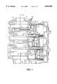
- FIG. 1is a section view of one row of three cylinders of a V-6 internal combustion engine
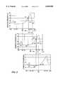
- FIG. 2is a graphical representation of a pressure profile within a crankcase of an internal combustion engine
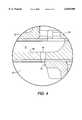
- FIG. 3shows three pressure profiles of the three cylinders illustrated in FIG. 1;
- FIG. 4is an enlarged view of a portion of FIG. 1.
- FIG. 1is a section view of an internal combustion engine which is taken through one row of three cylinders of a V-6 engine.
- the engine block 10defines three cylinder, 21, 22, and 23.
- Three pistons, 31, 32, and 33,are shown disposed in their associated cylinders for reciprocating motion therein.
- Each pistonhas a connecting rod, 41, 42, and 43, which, in turn, is attached to a crankshaft (not shown in FIG. 1) that rotates about a rotational axis 50.
- a lower cover 54is attached to the engine block 10 at parting line 56, to define three crankcase chambers, 61, 62, and 63.
- each cylinderhas a transfer passage.
- These transfer passages, 71, 72, and 73provide a fluid passage from a region below the associated piston to a region above the associated piston when the piston is within a certain range of travel within the cylinder. This allows pressurized gases to flow from the crankcase chamber into the combustion chamber by passing around the length of the piston and through the transfer passage, from left to right in FIG. 1.
- the magnitude of the pressure within their respective crankcases, 61-63fluctuates in response to the reciprocating movement of the associated piston.
- TDCtop dead center
- the pistonmoves toward its top dead center (TDC) position toward the right in FIG. 1, it decreases the pressure within the crankcase and causes air to be drawn into the crankcase through reed valves (not shown in FIG. 1) in a manner that is generally well known to those skilled in the art.
- BDCbottom dead center
- FIG. 2is a graphical representation of a typical crankcase pressure, measured in kilopascals. Each kilopascal is equivalent to 1,000 newtons per square meter.
- the horizontal axis in FIG. 2represents the piston position measured with respect to the angular position of the crankshaft. Beginning at point 101, when the piston is at its top dead center (TDC) position, the crankcase pressure begins to rise as the piston moves toward its bottom dead center position (toward the left in FIG. 1). This rise is generally continuous until the piston reaches a position, at approximately 120° after top dead center (ATDC) when it is at a position that allows the crankcase gases to flow through a transfer passage from below the piston to the combustion chamber above the piston.
- TDCtop dead center
- ATDCtop dead center
- the top piston 31is almost at the leftmost extreme of that position.
- its transfer passage 71would freely allow pressurized gas to flow from the crankcase 61 to the cylinder 21 above the piston 31. This results in a rapid decrease in the pressure of the crankcase. This pressure decrease occurs between points 102 and 103 in FIG. 2. Point 103 in FIG. 2 coincides with the closing of the transfer passage.
- the graphical representation in FIG. 2shows the total pressure profile of a crankcase as a function of the position of the piston for one complete rotation of the crankshaft.
- crankshaftcauses the reciprocating motions of the pistons within their respective cylinders.
- These reciprocating motionscause the respective crankcases to experience pressure changes represented graphically in FIG. 2.
- the pistonsare not in phase with each other. Therefore, the instantaneous pressures within the crankcases, 61-63, will vary from crankcase to crankcase, as a function of the relative positions of their respective pistons.
- a wall 80separates the adjacent cylinders.
- One wall 80separates the top cylinder 21 from the middle cylinder 22 and another wall 80 separates the middle cylinder 22 from the bottom cylinder 23.
- each of these walls 80is provided with a fluid passage 90 extending through it.
- the fluid passage 90intersects the transfer passage, 71 or 72, of the cylinder above the wall.
- the fluid passageis alternatively blocked an unblocked by the piston below the fluid passage 90. As the pistons move in their reciprocated motion, they alternately block and unblock the fluid passages 90 extending toward their respective cylinders from the cylinder above. For example, in FIG.
- the fluid passage 90 extending downward toward the bottom cylinder 23is unblocked because the piston 33 is located sufficiently toward its top dead center (TDC) position.
- the fluid passages 90 through wall 80 extending downward toward the middle cylinder 22is blocked because piston 32 has moved from its top dead center (TDC) position, toward the left in FIG. 1, and blocked it.
- FIG. 1The portion of FIG. 1 contained within the circular dashed line F4 is shown in an enlarged view in FIG. 4.
- any liquid collecting in a pool within the transfer passage 72will be forced downward through the fluid passage 90 into the lower cylinder 23 if the fluid passage 90 is unblocked by piston 33 and if the pressure within the transfer passage 72 is greater than the pressure within the portion of cylinder 23 below the piston 33.
- the pressure below the piston 33 within cylinder 23is generally identical to magnitude to the pressure of crankcase 63.
- FIG. 3is a composite of three graphical segments representing the pressure profiles of the three crankcases shown in FIG. 1.
- the three pistons causing the pressure profiles in FIG. 3are out of phase with each other by a magnitude of 120° of crankshaft rotation. Therefore, when the top piston 31 is creating the crankcase pressure profile 201, the middle piston 32 is at a position 120° before top dead center (TDC) and creating the pressure profile 202 in FIG. 3.
- the bottom piston 33creates the crankcase pressure profile 203 and is 120° behind the middle piston 32.
- the dashed vertical lines in FIG. 3identify common points in time for the three pressure profiles.
- the top crankcase 61is at a pressure of approximately 115 kilopascals at the same time that the middle crankcase 62 is at a pressure slightly less than 95 kilopascals.
- These pressure magnitudeshave been empirically determined to be 118 kilopascals and 93 kilopascals, respectively. Therefore, at the time identified by dashed line 300, a pressure differential of 25 kilopascals exists between the top crankcase 61 and the middle crankcase 62.
- the same basic principlesare employed to cause a flow of fluid through the fluid passage 90 in the wall 80 between the middle cylinder 22 and the bottom cylinder 23.
- This flowoccurs between dashed lines 500 and 510, during the period identified as P2. Because the pressure represented by point 501 in the middle crankcase 62 is greater than the pressure represented by point 502 in the bottom crankcase 63, a pressure differential causes fluid to flow downward through the fluid passage 90 in the wall 80 between the middle and bottom cylinders, 22 and 23 respectively.
- the fluid passages 90are located at an axial position along the cylinder wall that coincides with the bottom edge of the piston skirt when the piston is at a position of approximately 37° of crankshaft rotation from the top dead center (TDC) position of the piston.
- TDCtop dead center
- the piston skirtunblocks the fluid passage 90 at a position of 37° before top dead center (BTDC) and leaves the fluid passage 90 unblocked until it reaches its top dead center (TDC) and continues to the position of 37° after top dead center (ATDC).
- the fluid passage 90remains unblocked only while the pressure within the upper transfer passage 71 is greater than the pressure in the lower crankcase 62.
- the fluid passage 90 between the middle and bottom cylindersremains unblocked by piston 33 only while the pressure in the transfer passage 72 is greater than the pressure in the lower crankcase 63.
- cylinder 23is the lowest cylinder in the row of cylinders. Therefore, the pooled lubricant in the transfer passage 73 can not be pumped into a lower cylinder. Therefore, a lubricant aperture 700 is provided in the lowest transfer passage 73.
- the lubricant aperture 700can then be connected to a conduit, such as a plastic tube, and conducted upward to the barbed fitting of nipple 704 of a check valve which is attached to the engine block 10 and disposed in fluid communication with a fluid passage 710 that leads to an opening 712 in the cylinder wall of the uppermost cylinder 21.
- the pressure differential between the transfer passage 73 and the upper crankcase 61is such that the liquid lubricant pooled in the lowest transfer passage 73 can be pumped up to the nipple 704 by the differential pressures.
- the present inventionsolves two problems relating to internal combustion engines. First, it pumps liquid lubricant to the walls of the cylinders to improve the lubrication between the cylinder walls and the piston rings. Secondly, the present invention removes pooled liquid lubricant from the transfer passages where it would serve no other useful purpose. Instead of causing the liquid lubricant to be forced from the transfer passages into the combustion chambers of the associated cylinders, the present invention removes the pooled lubricant from the transfer passages and pumps it downward through the fluid passages into the cylinder below where it can provide the useful lubrication of the cylinder walls.
Landscapes
- Engineering & Computer Science (AREA)
- Mechanical Engineering (AREA)
- General Engineering & Computer Science (AREA)
- Lubrication Of Internal Combustion Engines (AREA)
Abstract
Description
Claims (17)
Priority Applications (1)
| Application Number | Priority Date | Filing Date | Title |
|---|---|---|---|
| US09/356,686US6058900A (en) | 1999-07-20 | 1999-07-20 | Internal combustion engine with improved cylinder wall lubrication system |
Applications Claiming Priority (1)
| Application Number | Priority Date | Filing Date | Title |
|---|---|---|---|
| US09/356,686US6058900A (en) | 1999-07-20 | 1999-07-20 | Internal combustion engine with improved cylinder wall lubrication system |
Publications (1)
| Publication Number | Publication Date |
|---|---|
| US6058900Atrue US6058900A (en) | 2000-05-09 |
Family
ID=23402503
Family Applications (1)
| Application Number | Title | Priority Date | Filing Date |
|---|---|---|---|
| US09/356,686Expired - LifetimeUS6058900A (en) | 1999-07-20 | 1999-07-20 | Internal combustion engine with improved cylinder wall lubrication system |
Country Status (1)
| Country | Link |
|---|---|
| US (1) | US6058900A (en) |
Cited By (7)
| Publication number | Priority date | Publication date | Assignee | Title |
|---|---|---|---|---|
| US6138634A (en)* | 1997-12-10 | 2000-10-31 | Brunswick Corporation | Oil lubrication system for an internal combustion engine |
| US6318331B1 (en)* | 1998-08-18 | 2001-11-20 | Sanshin Kogyo Kabushiki Kaisha | Lubrication system for direct injected engine |
| US20030136369A1 (en)* | 2002-01-22 | 2003-07-24 | Haman David F. | Method and apparatus for inter-cylinder lubrication transfer in a multi-cylinder internal combustion engine |
| US20100006056A1 (en)* | 2006-07-21 | 2010-01-14 | Jan Aamand | Lubricating apparatus for a dosing system for cylinder lubrication oil and method for dosing cylinder lubricating oil |
| US20100024759A1 (en)* | 2008-07-31 | 2010-02-04 | Dobransky Gary E | Two-stroke engine |
| US8813714B2 (en) | 2009-06-23 | 2014-08-26 | Hans Jensen Lubricators A/S | Lubrication of cylinders of large diesel engines, such as marine engines |
| US10724407B1 (en) | 2018-01-12 | 2020-07-28 | Brunswick Corporation | Apparatuses for lubricating cranktrains of outboard motors |
Citations (6)
| Publication number | Priority date | Publication date | Assignee | Title |
|---|---|---|---|---|
| US2326A (en)* | 1841-11-03 | Manner of securing and fastening the rails of bedsteads | ||
| US2136293A (en)* | 1936-11-23 | 1938-11-08 | Hermond G Gentry | Internal combustion engine |
| US2556273A (en)* | 1947-03-07 | 1951-06-12 | Hedges Motor Company | Internal-combustion engine cylinder lubrication |
| US4672931A (en)* | 1985-06-04 | 1987-06-16 | B-Art S.A.S. | Lubrication system with oil recovery for a two-stroke engine piston with pump-sump for scavenging |
| US4993380A (en)* | 1990-01-02 | 1991-02-19 | Hsu Shin I | Lubrication mechanism of engine cylinder |
| US5611302A (en)* | 1995-06-30 | 1997-03-18 | Daimler-Benz Ag | Two cycle internal combustion engine with unidirectional flow scavenging |
- 1999
- 1999-07-20USUS09/356,686patent/US6058900A/ennot_activeExpired - Lifetime
Patent Citations (6)
| Publication number | Priority date | Publication date | Assignee | Title |
|---|---|---|---|---|
| US2326A (en)* | 1841-11-03 | Manner of securing and fastening the rails of bedsteads | ||
| US2136293A (en)* | 1936-11-23 | 1938-11-08 | Hermond G Gentry | Internal combustion engine |
| US2556273A (en)* | 1947-03-07 | 1951-06-12 | Hedges Motor Company | Internal-combustion engine cylinder lubrication |
| US4672931A (en)* | 1985-06-04 | 1987-06-16 | B-Art S.A.S. | Lubrication system with oil recovery for a two-stroke engine piston with pump-sump for scavenging |
| US4993380A (en)* | 1990-01-02 | 1991-02-19 | Hsu Shin I | Lubrication mechanism of engine cylinder |
| US5611302A (en)* | 1995-06-30 | 1997-03-18 | Daimler-Benz Ag | Two cycle internal combustion engine with unidirectional flow scavenging |
Cited By (10)
| Publication number | Priority date | Publication date | Assignee | Title |
|---|---|---|---|---|
| US6138634A (en)* | 1997-12-10 | 2000-10-31 | Brunswick Corporation | Oil lubrication system for an internal combustion engine |
| US6318331B1 (en)* | 1998-08-18 | 2001-11-20 | Sanshin Kogyo Kabushiki Kaisha | Lubrication system for direct injected engine |
| US20030136369A1 (en)* | 2002-01-22 | 2003-07-24 | Haman David F. | Method and apparatus for inter-cylinder lubrication transfer in a multi-cylinder internal combustion engine |
| WO2003062610A1 (en)* | 2002-01-22 | 2003-07-31 | Bombardier Motor Corporation Of America | Method and apparatus for inter-cylinder lubrication transfer in a multi-cylinder internal combustion engine |
| US6845744B2 (en)* | 2002-01-22 | 2005-01-25 | Bombardier Recreational Products Inc. | Method and apparatus for inter-cylinder lubrication transfer in a multi-cylinder internal combustion engine |
| US20100006056A1 (en)* | 2006-07-21 | 2010-01-14 | Jan Aamand | Lubricating apparatus for a dosing system for cylinder lubrication oil and method for dosing cylinder lubricating oil |
| US8210317B2 (en)* | 2006-07-21 | 2012-07-03 | Hans Jensen Lubricators A/S | Lubricating apparatus for a dosing system for cylinder lubrication oil and method for dosing cylinder lubricating oil |
| US20100024759A1 (en)* | 2008-07-31 | 2010-02-04 | Dobransky Gary E | Two-stroke engine |
| US8813714B2 (en) | 2009-06-23 | 2014-08-26 | Hans Jensen Lubricators A/S | Lubrication of cylinders of large diesel engines, such as marine engines |
| US10724407B1 (en) | 2018-01-12 | 2020-07-28 | Brunswick Corporation | Apparatuses for lubricating cranktrains of outboard motors |
Similar Documents
| Publication | Publication Date | Title |
|---|---|---|
| EP0003439B1 (en) | Internal combustion engine | |
| CA1314777C (en) | Crankcase breather and lubrication oil system for an internal combustion engine | |
| US20080202483A1 (en) | Reduced-emission single cylinder engine | |
| US5881686A (en) | Crankcase breather valve for engines with synchronous piston movement | |
| CA1083484A (en) | Drain recycle system for two-cycle engine | |
| US2983334A (en) | 2-cycle engine | |
| US6058900A (en) | Internal combustion engine with improved cylinder wall lubrication system | |
| CA2674151C (en) | Two-stroke engine | |
| US5513608A (en) | Two cycle engine lubricating system | |
| JPH0625528B2 (en) | Two-stroke internal combustion engine | |
| US4256064A (en) | Fuel conserving engine improvement | |
| US9145845B2 (en) | Ventilation slots in a cylinder wall | |
| US4831979A (en) | Wrist pin lubrication system for two-cycle engines | |
| US3931812A (en) | Internal combustion engines | |
| EP2052135B1 (en) | Crankcase for an internal combustion engine | |
| US6012421A (en) | Internal combustion engine with improved lubrication system | |
| US4742803A (en) | Reciprocatory internal combustion engine | |
| US4331065A (en) | Engine piston assembly with improved oil control | |
| EP3803079B1 (en) | Double acting piston engines | |
| US6067952A (en) | Cylinder bore lubrication with residual oil | |
| US6845744B2 (en) | Method and apparatus for inter-cylinder lubrication transfer in a multi-cylinder internal combustion engine | |
| JPH0748966Y2 (en) | Crankcase ventilation system for internal combustion engine | |
| US20200173357A1 (en) | Internal combustion engine with two working spaces of a cylinder | |
| EP0242044B1 (en) | Gas compressors | |
| JP3355096B2 (en) | 2 cycle engine |
Legal Events
| Date | Code | Title | Description |
|---|---|---|---|
| AS | Assignment | Owner name:BRUNSWICK CORPORATION, ILLINOIS Free format text:ASSIGNMENT OF ASSIGNORS INTEREST;ASSIGNORS:KUSCHE, DAVID W.;ANDRASKO, NEIL M.;REEL/FRAME:010119/0240 Effective date:19990720 | |
| STCF | Information on status: patent grant | Free format text:PATENTED CASE | |
| FPAY | Fee payment | Year of fee payment:4 | |
| FPAY | Fee payment | Year of fee payment:8 | |
| AS | Assignment | Owner name:JPMORGAN CHASE BANK, N.A., TEXAS Free format text:SECURITY AGREEMENT;ASSIGNORS:BRUNSWICK CORPORATION;TRITON BOAT COMPANY, L.P.;ATTWOOD CORPORATION;AND OTHERS;REEL/FRAME:022092/0365 Effective date:20081219 Owner name:JPMORGAN CHASE BANK, N.A.,TEXAS Free format text:SECURITY AGREEMENT;ASSIGNORS:BRUNSWICK CORPORATION;TRITON BOAT COMPANY, L.P.;ATTWOOD CORPORATION;AND OTHERS;REEL/FRAME:022092/0365 Effective date:20081219 | |
| AS | Assignment | Owner name:THE BANK OF NEW YORK MELLON TRUST COMPANY, N.A., I Free format text:SECURITY AGREEMENT;ASSIGNORS:BRUNSWICK CORPORATION;ATTWOOD CORPORATION;BOSTON WHALER, INC.;AND OTHERS;REEL/FRAME:023180/0493 Effective date:20090814 Owner name:THE BANK OF NEW YORK MELLON TRUST COMPANY, N.A.,IL Free format text:SECURITY AGREEMENT;ASSIGNORS:BRUNSWICK CORPORATION;ATTWOOD CORPORATION;BOSTON WHALER, INC.;AND OTHERS;REEL/FRAME:023180/0493 Effective date:20090814 | |
| AS | Assignment | Owner name:LAND 'N' SEA DISTRIBUTING, INC., FLORIDA Free format text:RELEASE BY SECURED PARTY;ASSIGNOR:JPMORGAN CHASE BANK, N.A., AS ADMINISTRATIVE AGENT;REEL/FRAME:026026/0001 Effective date:20110321 Owner name:TRITON BOAT COMPANY, L.P., TENNESSEE Free format text:RELEASE BY SECURED PARTY;ASSIGNOR:JPMORGAN CHASE BANK, N.A., AS ADMINISTRATIVE AGENT;REEL/FRAME:026026/0001 Effective date:20110321 Owner name:BRUNSWICK COMMERICAL & GOVERNMENT PRODUCTS, INC., Free format text:RELEASE BY SECURED PARTY;ASSIGNOR:JPMORGAN CHASE BANK, N.A., AS ADMINISTRATIVE AGENT;REEL/FRAME:026026/0001 Effective date:20110321 Owner name:ATTWOOD CORPORATION, MICHIGAN Free format text:RELEASE BY SECURED PARTY;ASSIGNOR:JPMORGAN CHASE BANK, N.A., AS ADMINISTRATIVE AGENT;REEL/FRAME:026026/0001 Effective date:20110321 Owner name:BRUNSWICK CORPORATION, ILLINOIS Free format text:RELEASE BY SECURED PARTY;ASSIGNOR:JPMORGAN CHASE BANK, N.A., AS ADMINISTRATIVE AGENT;REEL/FRAME:026026/0001 Effective date:20110321 Owner name:BRUNSWICK BOWLING & BILLIARDS CORPORATION, ILLINOI Free format text:RELEASE BY SECURED PARTY;ASSIGNOR:JPMORGAN CHASE BANK, N.A., AS ADMINISTRATIVE AGENT;REEL/FRAME:026026/0001 Effective date:20110321 Owner name:LUND BOAT COMPANY, MINNESOTA Free format text:RELEASE BY SECURED PARTY;ASSIGNOR:JPMORGAN CHASE BANK, N.A., AS ADMINISTRATIVE AGENT;REEL/FRAME:026026/0001 Effective date:20110321 Owner name:BOSTON WHALER, INC., FLORIDA Free format text:RELEASE BY SECURED PARTY;ASSIGNOR:JPMORGAN CHASE BANK, N.A., AS ADMINISTRATIVE AGENT;REEL/FRAME:026026/0001 Effective date:20110321 Owner name:BRUNSWICK LEISURE BOAT COMPANY, LLC, INDIANA Free format text:RELEASE BY SECURED PARTY;ASSIGNOR:JPMORGAN CHASE BANK, N.A., AS ADMINISTRATIVE AGENT;REEL/FRAME:026026/0001 Effective date:20110321 Owner name:BRUNSWICK FAMILY BOAT CO. INC., WASHINGTON Free format text:RELEASE BY SECURED PARTY;ASSIGNOR:JPMORGAN CHASE BANK, N.A., AS ADMINISTRATIVE AGENT;REEL/FRAME:026026/0001 Effective date:20110321 | |
| AS | Assignment | Owner name:JPMORGAN CHASE BANK, N.A., AS ADMINISTRATIVE AGENT Free format text:SECURITY AGREEMENT;ASSIGNORS:BRUNSWICK CORPORATION;ATTWOOD CORPORATION;BOSTON WHALER, INC.;AND OTHERS;REEL/FRAME:026072/0239 Effective date:20110321 | |
| FPAY | Fee payment | Year of fee payment:12 | |
| AS | Assignment | Owner name:BRUNSWICK CORPORATION, ILLINOIS Free format text:RELEASE BY SECURED PARTY;ASSIGNOR:THE BANK OF NEW YORK MELLON;REEL/FRAME:031973/0242 Effective date:20130717 | |
| AS | Assignment | Owner name:LAND 'N' SEA DISTRIBUTING, INC., ILLINOIS Free format text:RELEASE BY SECURED PARTY;ASSIGNOR:JPMORGAN CHASE BANK, N.A.;REEL/FRAME:034794/0300 Effective date:20141226 Owner name:LUND BOAT COMPANY, ILLINOIS Free format text:RELEASE BY SECURED PARTY;ASSIGNOR:JPMORGAN CHASE BANK, N.A.;REEL/FRAME:034794/0300 Effective date:20141226 Owner name:BRUNSWICK CORPORATION, ILLINOIS Free format text:RELEASE BY SECURED PARTY;ASSIGNOR:JPMORGAN CHASE BANK, N.A.;REEL/FRAME:034794/0300 Effective date:20141226 Owner name:BRUNSWICK COMMERCIAL & GOVERNMENT PRODUCTS, INC., Free format text:RELEASE BY SECURED PARTY;ASSIGNOR:JPMORGAN CHASE BANK, N.A.;REEL/FRAME:034794/0300 Effective date:20141226 Owner name:BRUNSWICK LEISURE BOAT COMPANY, LLC, ILLINOIS Free format text:RELEASE BY SECURED PARTY;ASSIGNOR:JPMORGAN CHASE BANK, N.A.;REEL/FRAME:034794/0300 Effective date:20141226 Owner name:BRUNSWICK FAMILY BOAT CO. INC., ILLINOIS Free format text:RELEASE BY SECURED PARTY;ASSIGNOR:JPMORGAN CHASE BANK, N.A.;REEL/FRAME:034794/0300 Effective date:20141226 Owner name:ATTWOOD CORPORATION, ILLINOIS Free format text:RELEASE BY SECURED PARTY;ASSIGNOR:JPMORGAN CHASE BANK, N.A.;REEL/FRAME:034794/0300 Effective date:20141226 Owner name:BRUNSWICK BOWLING & BILLIARDS CORPORATION, ILLINOI Free format text:RELEASE BY SECURED PARTY;ASSIGNOR:JPMORGAN CHASE BANK, N.A.;REEL/FRAME:034794/0300 Effective date:20141226 Owner name:BOSTON WHALER, INC., ILLINOIS Free format text:RELEASE BY SECURED PARTY;ASSIGNOR:JPMORGAN CHASE BANK, N.A.;REEL/FRAME:034794/0300 Effective date:20141226 |