US6058531A - Dual-position assist and guard rail for beds - Google Patents
Dual-position assist and guard rail for bedsDownload PDFInfo
- Publication number
- US6058531A US6058531AUS08/862,245US86224597AUS6058531AUS 6058531 AUS6058531 AUS 6058531AUS 86224597 AUS86224597 AUS 86224597AUS 6058531 AUS6058531 AUS 6058531A
- Authority
- US
- United States
- Prior art keywords
- bed
- rail
- degree
- mounting
- rotatable
- Prior art date
- Legal status (The legal status is an assumption and is not a legal conclusion. Google has not performed a legal analysis and makes no representation as to the accuracy of the status listed.)
- Expired - Lifetime
Links
- 238000003466weldingMethods0.000claimsdescription5
- 230000006872improvementEffects0.000abstractdescription7
- 230000007246mechanismEffects0.000description17
- 210000002414legAnatomy0.000description5
- 208000027418Wounds and injuryDiseases0.000description4
- 230000006378damageEffects0.000description4
- 230000000994depressogenic effectEffects0.000description4
- 208000014674injuryDiseases0.000description4
- 210000003127kneeAnatomy0.000description2
- 230000004048modificationEffects0.000description2
- 238000012986modificationMethods0.000description2
- 230000009471actionEffects0.000description1
- 230000004888barrier functionEffects0.000description1
- 230000008859changeEffects0.000description1
- 238000004140cleaningMethods0.000description1
- 238000010276constructionMethods0.000description1
- 210000003414extremityAnatomy0.000description1
- 239000007924injectionSubstances0.000description1
- 238000002347injectionMethods0.000description1
- 235000000396ironNutrition0.000description1
- 230000000452restraining effectEffects0.000description1
- 238000011282treatmentMethods0.000description1
Images


Classifications
- A—HUMAN NECESSITIES
- A61—MEDICAL OR VETERINARY SCIENCE; HYGIENE
- A61G—TRANSPORT, PERSONAL CONVEYANCES, OR ACCOMMODATION SPECIALLY ADAPTED FOR PATIENTS OR DISABLED PERSONS; OPERATING TABLES OR CHAIRS; CHAIRS FOR DENTISTRY; FUNERAL DEVICES
- A61G7/00—Beds specially adapted for nursing; Devices for lifting patients or disabled persons
- A61G7/05—Parts, details or accessories of beds
- A61G7/0507—Side-rails
- A—HUMAN NECESSITIES
- A47—FURNITURE; DOMESTIC ARTICLES OR APPLIANCES; COFFEE MILLS; SPICE MILLS; SUCTION CLEANERS IN GENERAL
- A47C—CHAIRS; SOFAS; BEDS
- A47C21/00—Attachments for beds, e.g. sheet holders or bed-cover holders; Ventilating, cooling or heating means in connection with bedsteads or mattresses
- A47C21/08—Devices for prevention against falling-out, e.g. detachable side walls
- A—HUMAN NECESSITIES
- A61—MEDICAL OR VETERINARY SCIENCE; HYGIENE
- A61G—TRANSPORT, PERSONAL CONVEYANCES, OR ACCOMMODATION SPECIALLY ADAPTED FOR PATIENTS OR DISABLED PERSONS; OPERATING TABLES OR CHAIRS; CHAIRS FOR DENTISTRY; FUNERAL DEVICES
- A61G7/00—Beds specially adapted for nursing; Devices for lifting patients or disabled persons
- A61G7/05—Parts, details or accessories of beds
- A61G7/0507—Side-rails
- A61G7/0508—Side-rails characterised by a particular connection mechanism
- A61G7/0509—Side-rails characterised by a particular connection mechanism sliding or pivoting downwards
- A—HUMAN NECESSITIES
- A61—MEDICAL OR VETERINARY SCIENCE; HYGIENE
- A61G—TRANSPORT, PERSONAL CONVEYANCES, OR ACCOMMODATION SPECIALLY ADAPTED FOR PATIENTS OR DISABLED PERSONS; OPERATING TABLES OR CHAIRS; CHAIRS FOR DENTISTRY; FUNERAL DEVICES
- A61G7/00—Beds specially adapted for nursing; Devices for lifting patients or disabled persons
- A61G7/05—Parts, details or accessories of beds
- A61G7/0507—Side-rails
- A61G7/0512—Side-rails characterised by customised length
- A61G7/0513—Side-rails characterised by customised length covering particular sections of the bed, e.g. one or more partial side-rail sections along the bed
Definitions
- This inventionrelates to side guards or rails for beds. More particularly, it relates to such side guards or rails which are movable between two differently-oriented, positively-stopped and locked positions, and to mechanisms to enable the moving of the rails between such positions.
- One particularly useful such railis for hospital beds.
- the assist and guard railis useful for all beds having a side rail framework.
- standard hospital-type bedsgenerally now include side rails which may be of two types.
- One typecomprised a single-piece tubular side rail structure which extended substantially the length of the bed and which must be lifted off to allow the patient to be moved, or, if the patient was movable, to allow the patient to exit or to enter the bed.
- the other typical typecomprised a similar side rail structure which had a complicated and expensive hinged mechanism to allow the side rail to be lowered to the floor. This was thought to be more convenient for the aide, but it was impossible for the patient to manoeuvre if the patient was in the bed.
- Parallel links or armsconstitute one arrangement for supporting a side guard so that it will move easily between the two positions.
- two parallel armsextended between the side guard and the movable back section on which the head end of the mattress rested, those links being of equal length and rotatably connected both to the side guard and the back section.
- the side guardmoved upwardly or downwardly when the links rotated, yet remained at the same angle with respect to the back section.
- the two parallel armsmust be quite long. This, however, detracted from the stability of the side guard, making it somewhat wobbly in its upper position. It further caused the side guard to undergo a lengthy translational movement when passing between the two positions, and this requires considerable clearance at the end of the side guard.
- Another typical bed rail mechanismused vertical support members which were slidably attached to the bed frame such that the bed rail can be raised and lowered vertically. These sliding-type mechanisms typically locked the bed rail in the raised position by use of a pin engaging a hole in the vertical support member or by a clamping means. That mechanism had been subject to the loss of component parts. Further, such bed rails can be relatively heavy and awkward for a given operator to raise and lower. If such bed rails were not lowered evenly, they tended to bind, become difficult to move and can jam in an undesired position.
- U.S. Pat. No. 2,817,855patented by Pratt, disclosed a guard frame which was pivotally mounted upon a frame member of a bed and was movable from an upper guarding position to a lower unguarding position by rotating its supporting members around the pivotal mountings.
- a pair of link armswas pivoted to the brackets and was swingable through a vertical plane.
- a rigid frame of generally quadrilateral configurationwas provided, the frame having adjacent corner portions that were pivoted to the free ends of the link arms, so that the opposed sides of the frame may be moved into and out of position in alignment with the link members upon relative pivotal movement there between.
- At least one bracketwas provided which had a U-shaped pocket within which the link arm which was pivoted thereto may be received, with the link arm being in alignment with an opposed side of the frame.
- U.S. Pat. No. 3,055,020patented Sep. 25, 1962, by Stuart Nelson Mann, provided a restraining structure for beds, which comprised a parallelogram linkage. It included a pair of spaced upright channel members which were disposed with their open side facing with other and which were adapted to be pivoted at their lower ends to the side portion of the framework of a bed. Flanged portions of the channel members had portions projecting therefrom toward the other channel member to form pairs of spaced bearing portions which were offset substantially from the channel members proper. A plurality of vertically-spaced, horizontally-extending tubular members had their ends pivoted between pairs of the bearing portions to form a parallelogram linkage.
- Stop meanswere provided for limiting downward pivotal movement of the upright members to a predetermined oblique position.
- the pivot axes of the barswere offset from the channel members proper by a sufficient distance so that, during collapsing movement of the parallelogram linkage, the approaching sides of the channel members and the tubular members maintained substantial spacing to avoid pinching.
- U.S. Pat. No. 3,585,659patented Jun. 22, 1971, by Francis J. Burst et al, provided a safety side guard for hospital beds.
- the guardwas mounted upon the mattress supporting frame of the bed by mounting means that included trunnions which were journalled in a mounting bracket that was fixed upon the frame.
- the guardwas movable from an elevated guarding position to a lowered inoperative position, causing rotation of the trunnions in their journals.
- a spring pressed latchwhich was mounted in the bracket secured the guard in elevated position, and top means limited movement of the guard both up and down.
- the mounting bracketwas mounted on the frame and was disposed well below the patient in the bed, and hence, was not readily accessible to the patient, although it was readily accessible to a nurse when it was desired to lower the guard.
- the safety bed rail assemblyincluded a pivot assembly which was adapted to allow movement between the raised and the lower position without injury to the operator. In its raised position, the safety rail prevented persons in bed from falling out of bed and provided useful assistance in moving into and out of bed.
- the guardIn the lowered position, the guard was positioned below the mattress level to allow a nurse or other bed attendant to tuck bed clothes under the mattress without the rail obstructing the operation and to move easily around the bed and patient to administer injections or other treatments.
- the railWhen so lowered, the rail was spaced sufficiently above the floor to provide clearance for cleaning and movement of stands and the like thereunder.
- U.S. Pat. No. 4,612,679patented Sep. 23, 1986, by Larry D. Mitchell, provided a bed side guard assembly, which was movable between elevated and depressed positions on parallel swing arms that were quite short and extended from a base which was mounted on the back section of the bed. It had an upper section which pivoted outwardly and downwardly to a retracted position substantially to reduce the height of the side guard. When the side guard was in its depressed position with its upper section folded to the retracted position, the side guard lay entirely below the mattress supporting surface of the bed back section and therefore did not interfere with bed making.
- the parallel swing armshad spindles which projected into the base, where they rotated as the side guard moved between its elevated and depressed positions, and those spindles carried crank arms that were connected by a tie bar.
- a latch boltlay in the path of the tie bar to hold the side guard in its elevated position. The tie bar, by coming against one or other of the spindles, prevented the side guard from going past its elevated or depressed positions.
- the mechanismused a movable framework to guide the bed rail in an arcuate path between its elevated and lower positions.
- a diagonal linkagewas provided to lock the mechanism and bed rail in the elevated position.
- a counterbalance mechanismwas also provided so the operator need not struggle with the weight of the rail.
- the side railwas rotatable so as to serve as a barrier. Rotation of the side rail only 90° was permitted to set the rail into its open stopped position.
- Optional engagable locking meanswere manually, but not automatically, operable to lock the rail in the closed position or in the open position.
- the bed guardwas movable between a first position maintaining the gap and a second position closing the gap to prevent patient movement through such gap.
- the closurehad a first end, which included a rotation means, the rotation means being carried by the guard rail.
- a first lockwas provided for securing the closure in a first locking position with the closure means being adapted to be positioned adjacent to, generally parallel to, and coextensive with, the guard rail, thereby maintaining the gap.
- a second lockwas provided for securing the closure in a second locking position closing the gap.
- the first and the second lockswere operated by a single handle. Means were provided for engaging the first and the second locking means.
- U.S. Pat. No. 5,384,927patented Jan. 31, 1995, by Steve Mardero et al., provided a security rail attachment for a bed, which included a post with an adjustable foot at the lower end.
- a rail portionwas mounted within the post and was rotatable about the vertical axis of the post.
- An attachment railextended across the end of the bed and included clamping elements for clamping to angle irons along the sides of the bed.
- the rotatable rail portioncould be latched at four 90° spaced-apart positions by notches in the base of a vertical post of the rail portion which cooperated with a transverse pin in the post.
- the rail portioncould therefore project outwardly from the bed at right angles thereto for assisting the occupant in standing, or could lie along the side of the bed to assist the occupant to prevent the occupant from falling from that side of the bed.
- a further object of this inventionis to provide a rail assembly that does not require a large clearance along the bed to accommodate the translational movement that accompanies the change between either of its two stopped positions.
- a still further object of this inventionis to provide a rail assembly which reduces the potential for injury to persons by providing controlled movement between an assist position and a guard position.
- Yet another object of this inventionis to provide an improved dual-position rail assembly for a bed.
- An additional object of this inventionis to provide a dual-position rail assembly which is relatively economical and which is easy to manipulate, and yet is low in cost.
- the present inventionin one embodiment, provides an improvement in a bed having a side rail structure, and at least one dual-position rail assembly which is mounted on such side rail structure, the improvement including: a rotatable structure which is mounted upon the dual-position rail assembly, to enable the dual-position rail assembly to move between two positively-stopped and automatically locked positions, a first of the positively-stopped and automatically locked positions disposing the dual-position rail assembly in an assist, vertically-oriented, position which is perpendicular to the longitudinal axis of the bed, and a second of such positively-stopped and automatically locked positions disposing the dual-position rail assembly in a guard, horizontally-oriented, position which is parallel to the longitudinal axis of the bed; and locking means for maintaining the dual-position rail assembly in an automatically locked selected one of the first positively-stopped and automatically locked position or the second positively-stopped and automatically locked position.
- the present inventionin another embodiment, provides a dual-position rail assembly for a bed comprising: a dual-position rail assembly; pivot means for supporting the dual-position rail assembly to enable the dual-position rail assembly to move between two positively-stopped and automatically locked positions, a first of the positively-stopped and automatically locked positions disposing the dual-position rail assembly in an assist, vertically-oriented, position which is perpendicular to the longitudinal axis of the bed, and a second of such positively-stopped and automatically locked positions disposing the dual-position rail assembly in a guard, horizontally-oriented, position which is parallel to the longitudinal axis of the bed, the positively-stopped and automatically locked positions being provided by means for limiting pivotal movement of the dual-position rail assembly, and by locking latch means for selectively, but automatically, locking the dual-position rail assembly in each of the first, positively-locked and automatically locked position and the second, positively-locked and automatically locked position; and including means for allowing the pivotal movement of the dual-position rail assembly between the two positively stopped and automatically locked positions.
- the present inventionin yet another embodiment, provides a dual-position rail assembly for a bed comprising: a support bracket; at least one pair of parallel rails which are secured to the support bracket; means for enabling pivoting of the combined support bracket and the parallel rails between two positively-stopped and automatically locked positions, a first of the positively-stopped and automatically locked positions disposing the combined support bracket and the parallel rails in an assist, vertically-oriented, position which is perpendicular to the longitudinal axis of the bed, and a second of such positively-stopped and automatically locked positions disposing the combined support bracket and the parallel rails in a guard, horizontally-oriented, position which is parallel to the longitudinal axis of the bed, the positively-stopped and automatically locked positions being provided by means for limiting pivotal movement of the combined support bracket and the parallel rails and by automatically lockable and latchable means for selectively holding the combined support bracket and the parallel rails in each of the first, positively-stopped and automatically locked position, and the second, positively-stopped and automatically locked position, for locking the pivotal
- the present inventionin a still further, and preferred, embodiment, provides a 90-degree-rotatable rail for mounting to a bed which has a side rail frame structure, comprising: a bracket structure for mounting to a side rail frame structure of the bed; a rail structure which is secured to the bracket, the rail structure comprising a rigid, quadrilateral framework with a pair of parallel legs supporting the framework, the legs being joined by a rectangular plate, the rectangular plate including an abutment plate secured thereto; a bilobed cam disc which is secured to the bracket structure and which is rotatably mounted with respect to the rectangular plate, the rail thereby being rotatable in a clockwise direction from a first, positively-stopped and automatically locked, orientation, where the length of the rectangular framework is parallel to the side rail, and where a first lobe of the bilobed cam disc abuts one face of the abutment plate, and being rotatable in a counter-clockwise direction from the first, positively-stopped and automatically locked orientation to a second
- the locking meanscomprises a pair of selectively engagable lock mechanisms.
- the bracket structure of the rail structurecomprises a U-shaped channel member which is fixedly secured to a base post and which extends perpendicularly therefrom.
- the bilobed cam plateis fixedly secured to the base post and extends perpendicularly thereto, whereby the longitudinal plane of the bilobed cam plate is parallel to the longitudinal plane of the U-shaped channel member.
- the fixed securingis by welding.
- the cooperating meanscomprises a pin which is mounted on the rectangular plate, and which is selectively movable to rest within a selected aperture of two 90 degree spaced-apart apertures in the bilobed cam disc.
- the pinis a spring-loaded pin.
- an additional longitudinally-extending baris provided within the rigid quadrilateral framework.
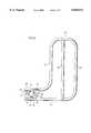
- FIG. 1is a perspective view of a bed including a dual-position rail assembly according to one embodiment of this invention
- FIG. 2is an enlarged end view of the embodiment of the dual-position rail assembly of one embodiment of this invention shown in FIG. 1;
- FIG. 3is an exploded perspective view of the dual-position rail assembly according to one embodiment of this invention for use on the right side of a bed;
- FIG. 4is a perspective view of the assembled embodiment of FIG. 3 for use on the left side of a bed;
- FIG. 5is an enlarged posterior view of the embodiment of the dual-position rail assembly of one embodiment of this invention shown in FIG. 1, in its substantially horizontal orientation (first or guard position), for use on the right side of a bed;
- FIG. 6is an enlarged posterior view of the embodiment of the dual-position rail assembly of one embodiment of this invention shown in FIG. 1, in its substantially vertical orientation (second or assist position), for use on the right side of a bed;
- FIG. 7is a cross-section through the dual-position rail assembly and bracket of one embodiment of this invention shown in FIG. 1, showing the locking mechanism;
- FIG. 8is a partial view of FIG. 6 showing the operation of the locking mechanism
- FIG. 9is a perspective view of the locking mechanism shown in FIG. 7 and FIG. 8.
- FIGS. 1 and 2One preferred embodiment of this invention is on a hospital bed.
- the hospital bed 10 as seen in FIGS. 1 and 2includes a headboard 11, a footboard 12 and a pair of side rails, (only one 13 being seen), extending therebetween on both sides of the bed.
- the rail structure 20is secured to the side rail 13 in a manner which is more clearly seen in FIGS. 2, 3 and 6.
- the rail structureincludes a U-shaped channel bracket 21 which is provided with aligned apertures 22,23 and 24,25, through which bolts 26,27, respectively, pass through bores (not shown) in the side rail 13, to be secured by way of nuts 28,29, respectively.
- a base post 30is secured at right angles to bracket 21 and extends transversely therefrom.
- a bilobed cam disc 31is secured at right angles to the base post 30 and extends longitudinally therefrom. Thus, the longitudinal plane of the cam disc 31 is parallel to the longitudinal plane of the bracket 21.
- the bilobed cam plate 31includes an upper corner, which is adjacent to the base post 30, and which is defined by a horizontal edge 32 and a vertical edge 33.
- the horizontal edge 32curves downwardly at arcuate edge 34 to end at first lobe 35.
- the vertical edge 33curves downwardly at arcuate edge 36 to end at second lobe 37.
- Cam plate 31includes a central bore 38 and two 90 degree spaced apart apertures, namely, aperture 39 which is adjacent to edge 32 and aperture 40 which is adjacent to edge 33.
- the rail 20, as seen in FIG. 1,includes a rectangular framework 41, which is provided by an upper horizontal bar 42 and a lower horizontal bar 43, the horizontal bars being joined by vertical bars 44,45.
- An auxiliary horizontal bar 46is also provided between vertical bars 44, 45.
- the vertical bar 44includes an extension providing one leg 47, and the lower horizontal bar merges with a second, and parallel, leg 48, (see also FIGS. 1, 5 and 6).
- the rectangular plate 49includes a bore 50 by means of which shaft/bolt 51 rotatably secures the rectangular plate 49 to the cam disc 31 by passing through aligned bores 50, 38.
- the rectangular plate 49is so rotatably secured to the cam disc 31 by nut 52.
- the rectangular plate 49also includes a counterbored aperture 53/54, (see also FIGS. 7, 8 and 9), within which a spring-loaded pin 55 is secured.
- the spring-loaded pin 55includes a sprung pin 56, as well as a spring (not seen).
- the rectangular plate 49is also provided with a vertically-oriented abutment plate 57, which is disposed adjacent to the bottom edge 59 of the rectangular plate 49.
- the rail 20is shown in FIG. 5 in its first (or guard rail) orientation. In such orientation, the first lobe 35 abuts against edge 60 of abutment plate 57, thereby to provide a stop.
- the pin 56is seen to rest in aperture 39 to provide a locked first orientation.
- the rail 20is shown in FIG. 6 in its second (assist rail) orientation.
- the second lobe 37abuts against edge 61 of abutment plate 57, thereby to provide a stop.
- the pin 56is seen to rest in aperture 40 to provide a locked second orientation.
Landscapes
- Health & Medical Sciences (AREA)
- Nursing (AREA)
- Life Sciences & Earth Sciences (AREA)
- Animal Behavior & Ethology (AREA)
- General Health & Medical Sciences (AREA)
- Public Health (AREA)
- Veterinary Medicine (AREA)
- Invalid Beds And Related Equipment (AREA)
Abstract
Description
Claims (20)
Priority Applications (2)
| Application Number | Priority Date | Filing Date | Title |
|---|---|---|---|
| US08/862,245US6058531A (en) | 1997-05-23 | 1997-05-23 | Dual-position assist and guard rail for beds |
| CA002223851ACA2223851C (en) | 1997-05-23 | 1997-12-05 | Dual assist and guard rail for beds |
Applications Claiming Priority (1)
| Application Number | Priority Date | Filing Date | Title |
|---|---|---|---|
| US08/862,245US6058531A (en) | 1997-05-23 | 1997-05-23 | Dual-position assist and guard rail for beds |
Publications (1)
| Publication Number | Publication Date |
|---|---|
| US6058531Atrue US6058531A (en) | 2000-05-09 |
Family
ID=25338023
Family Applications (1)
| Application Number | Title | Priority Date | Filing Date |
|---|---|---|---|
| US08/862,245Expired - LifetimeUS6058531A (en) | 1997-05-23 | 1997-05-23 | Dual-position assist and guard rail for beds |
Country Status (2)
| Country | Link |
|---|---|
| US (1) | US6058531A (en) |
| CA (1) | CA2223851C (en) |
Cited By (89)
| Publication number | Priority date | Publication date | Assignee | Title |
|---|---|---|---|---|
| US6240583B1 (en) | 1996-12-03 | 2001-06-05 | Hill-Rom, Inc. | Ambulatory assist arm for a bed |
| US6363552B1 (en) | 2000-03-17 | 2002-04-02 | Hill-Rom Services, Inc. | Bed siderail |
| WO2002032271A1 (en)* | 2000-10-19 | 2002-04-25 | Hill-Rom S.A.S. | Bed with articulated barrier elements |
| US6397416B2 (en)* | 1999-08-12 | 2002-06-04 | Hill-Rom Services, Inc. | Ambulatory assist arm for a bed |
| USD458481S1 (en) | 2001-04-05 | 2002-06-11 | Hill-Rom Services, Inc. | Slats of a bed siderail |
| USD459119S1 (en) | 2001-04-05 | 2002-06-25 | Hill-Rom Services, Inc. | Siderail support arm |
| USD463179S1 (en) | 2001-04-05 | 2002-09-24 | Hill-Rom Services, Inc. | Top rail member of a bed siderail |
| WO2003015686A1 (en)* | 2001-08-15 | 2003-02-27 | Hill-Rom Services, Inc. | Ambulatory assist arm apparatus |
| US6601251B2 (en) | 2000-05-30 | 2003-08-05 | Gerald S. Paul | Height adjustable medical bed including intermediate upper and lower stop positions |
| USD479070S1 (en) | 2002-09-06 | 2003-09-02 | Hill-Rom Services, Inc. | Bed siderail |
| US20030167568A1 (en)* | 2001-12-20 | 2003-09-11 | Brooke Jason C. | Bed siderails |
| WO2003017905A3 (en)* | 2001-08-22 | 2004-04-08 | Hill Rom Services Inc | Apparatus and method for closing hospital bed gaps |
| US20040168254A1 (en)* | 2003-02-28 | 2004-09-02 | Kevin Rabska | Assist handle assembly for beds |
| US6820293B2 (en) | 2002-09-26 | 2004-11-23 | Hill-Rom Services, Inc. | Bed siderail pad apparatus |
| US20050050635A1 (en)* | 2001-08-22 | 2005-03-10 | Metz Darrell L. | Apparatus and method for mounting hospital bed accessories |
| US20050071921A1 (en)* | 1999-10-15 | 2005-04-07 | Hill-Rom Services, Inc. | Siderail pad for hospital bed |
| US20050071922A1 (en)* | 2003-10-03 | 2005-04-07 | Roussy George Joseph | Bed with anti-rattle mechanism for a bed rail |
| US20060085912A1 (en)* | 2004-10-27 | 2006-04-27 | Kuek Devin W | Siderail support mechanism |
| US20060090260A1 (en)* | 2004-10-18 | 2006-05-04 | Stryker Martin W | Bed siderail |
| USD520783S1 (en)* | 2004-10-01 | 2006-05-16 | M.C. Healthcare Products Inc. | Rotating assist rail |
| US7073220B2 (en) | 2002-09-06 | 2006-07-11 | Hill-Rom Services, Inc. | Bed siderail having a latch |
| US7107636B2 (en) | 1999-03-19 | 2006-09-19 | Hill-Rom Services, Inc. | Gap filler for bed |
| US20070017029A1 (en)* | 2005-04-06 | 2007-01-25 | Wurdeman Byron W | Hospital beds with a rotating sleep surface that can translate into a chair configuration |
| US20070034162A1 (en)* | 2005-08-10 | 2007-02-15 | Sportpet Designs, Inc. | Collapsible birdhouse |
| US7200882B2 (en) | 2004-01-22 | 2007-04-10 | Hill-Rom Services, Inc. | Movable control panel for a patient support |
| GB2430614B (en)* | 2005-09-29 | 2008-05-28 | Proto Magic Innovations Ltd | Grab rail/cot side attachment for a mattress elevator |
| WO2008110361A1 (en)* | 2007-03-14 | 2008-09-18 | Spiroplex Gmbh | Side grate |
| US20090144899A1 (en)* | 2007-10-02 | 2009-06-11 | Standers, Inc. | Sliding mobility assistance device |
| US20090188042A1 (en)* | 2008-01-21 | 2009-07-30 | Stryker Corporation | Hospital bed |
| US20100000018A1 (en)* | 2008-07-04 | 2010-01-07 | Mario Cesar Eleonori | Side Guard for Bed |
| US7676862B2 (en)* | 2004-09-13 | 2010-03-16 | Kreg Medical, Inc. | Siderail for hospital bed |
| ITTO20080851A1 (en)* | 2008-11-18 | 2010-05-19 | Casaluci Giuliano S R L | BOTTOM OF A BED |
| US7805789B1 (en)* | 2009-02-27 | 2010-10-05 | Mark Ronald Dean | Assist handle for a bed |
| US20110010852A1 (en)* | 2009-07-15 | 2011-01-20 | Heimbrock Richard H | Medical line manager |
| US20110010857A1 (en)* | 2009-07-17 | 2011-01-20 | Falbo Sr Michael G | Cardiology gurney |
| US20110010864A1 (en)* | 2009-07-17 | 2011-01-20 | Jean-Bernard Duvert | Hospital bed equipped with a patient mobility aid device |
| US7917978B2 (en) | 2004-03-12 | 2011-04-05 | Hill-Rom Services, Inc. | Variable height siderail for a bed |
| US7930778B2 (en) | 2007-12-07 | 2011-04-26 | Hill-Rom Services, Inc. | Pinch-preventing unit for bed guardrail |
| US7934276B2 (en) | 2006-02-08 | 2011-05-03 | Hill-Rom Services, Inc. | End panel for a patient-support apparatus |
| US20110179590A1 (en)* | 2010-01-28 | 2011-07-28 | David Andrew Klimas | Swimming Pool Cleaners, and Associated Hoses and Connectors for Use with the Same |
| US20110185507A1 (en)* | 2010-02-02 | 2011-08-04 | Abernathey Ethan S | Assist handle assemblies and beds with an assist handle assembly |
| US8239986B2 (en) | 2008-03-13 | 2012-08-14 | Hill-Rom Services, Inc. | Siderail assembly for a patient-support apparatus |
| US8341778B2 (en) | 2011-02-07 | 2013-01-01 | Hill-Rom Services, Inc. | Bed gap filler and footboard pad |
| US8413270B2 (en) | 2010-11-03 | 2013-04-09 | Hill-Rom Services, Inc. | Siderail assembly for patient support apparatus |
| US8621688B2 (en) | 2010-12-13 | 2014-01-07 | Hill-Rom Services, Inc. | Siderail assembly for patient support apparatus |
| US8677535B2 (en) | 2010-10-08 | 2014-03-25 | Hill-Rom Services, Inc. | Patient support apparatus with storable egress handles |
| US8713727B2 (en) | 2010-07-30 | 2014-05-06 | Hill-Rom Services, Inc. | Siderail assembly for patient support apparatus |
| US8745786B2 (en) | 2010-11-10 | 2014-06-10 | Hill-Rom Services, Inc. | Siderail assembly for patient support apparatus |
| US8756735B2 (en) | 2011-02-08 | 2014-06-24 | Hill-Rom Services, Inc. | Patient helper with egress handle |
| USD708467S1 (en) | 2013-03-14 | 2014-07-08 | Invacare Corporation | Bed rail |
| USD710507S1 (en) | 2013-09-23 | 2014-08-05 | Hill-Rom Services Pte. Ltd. | Patient bed |
| USD710510S1 (en) | 2013-09-23 | 2014-08-05 | Hill-Rom Services Pte. Ltd. | Foot rail for a patient bed |
| USD710509S1 (en) | 2013-09-23 | 2014-08-05 | Hill-Rom Services Pte. Ltd. | Head rail for a patient bed |
| US20140259402A1 (en)* | 2013-03-14 | 2014-09-18 | Drive Medical Design & Mfg. | Adjustable side rail for medical beds and the like |
| WO2015039637A1 (en) | 2013-09-17 | 2015-03-26 | Linet Spol. S.R.O. | Bed guard assembly |
| US9060619B2 (en) | 2010-07-09 | 2015-06-23 | Hill-Rom Services, Inc. | Variable height siderail |
| US9101517B2 (en) | 2010-08-30 | 2015-08-11 | Hill-Rom Services, Inc. | Patient-support apparatus with a configurable siderail |
| JP2015202170A (en)* | 2014-04-11 | 2015-11-16 | 株式会社ナンシン | frame rotation structure of bedside |
| JP2015204924A (en)* | 2014-04-17 | 2015-11-19 | 株式会社ナンシン | frame rotation structure of bedside |
| US9205009B2 (en) | 2012-12-17 | 2015-12-08 | Hill-Rom Services, Inc. | Patient support apparatus having movable handles |
| US9265677B2 (en) | 2009-12-23 | 2016-02-23 | Piedmont 361, Llc | Hospital chair beds with stowable stand-assist supports |
| USD768422S1 (en) | 2014-08-12 | 2016-10-11 | Hill-Rom Services, Inc. | Foot end siderail |
| USD769042S1 (en) | 2014-08-12 | 2016-10-18 | Hill-Rom Services, Inc. | Head end siderail |
| USD770824S1 (en) | 2014-08-12 | 2016-11-08 | Hill-Rom Services, Inc. | Barrier for a hospital bed |
| USD771259S1 (en) | 2015-01-29 | 2016-11-08 | Hill-Rom Services, Inc. | Foot rail for patient bed |
| USD770829S1 (en) | 2015-01-29 | 2016-11-08 | Hill-Rom Services, Inc. | Head rail for patient bed |
| USD779074S1 (en)* | 2015-07-29 | 2017-02-14 | Midmark Corporation | Armrest for medical examination table |
| USD798641S1 (en)* | 2016-09-01 | 2017-10-03 | Stander Inc. | Bed rail |
| USD804882S1 (en) | 2016-05-28 | 2017-12-12 | Hill-Rom Services, Inc. | Headrail |
| USD804883S1 (en) | 2016-05-28 | 2017-12-12 | Hill-Rom Services, Inc. | Footrail |
| US10470955B2 (en) | 2014-03-11 | 2019-11-12 | Hill-Rom Services, Inc. | Patient bed having translatable siderail for bed exit |
| USD906749S1 (en)* | 2020-09-16 | 2021-01-05 | Gold Kernal Llc | Bed rail |
| USD909805S1 (en)* | 2018-02-15 | 2021-02-09 | Michael F. Kunde | Transfer bar |
| USD915118S1 (en)* | 2019-06-19 | 2021-04-06 | Vive Health LLC | Adjustable bed rail |
| US11229566B2 (en)* | 2018-06-08 | 2022-01-25 | Arjo Ip Holding Ab | Two-plane, folding patient assist handle |
| US11382436B1 (en) | 2018-06-14 | 2022-07-12 | Joseph Peter Vosters | Bed frame of a canopy style construction typically found in a home setting integrating assistive components therein |
| USD983585S1 (en)* | 2021-11-10 | 2023-04-18 | Arjo Ip Holding Ab | Grab handle for hospital bed |
| CZ309601B6 (en)* | 2015-02-09 | 2023-05-10 | Linet Spol. S R.O. | Arresting mechanism for automatically securing removable bed parts |
| US11653768B2 (en) | 2020-11-20 | 2023-05-23 | Stander Inc. | Bed handle |
| US20230210705A1 (en)* | 2020-04-30 | 2023-07-06 | Stryker Corporation | Side Rail Assembly For A Patient Support Apparatus |
| USD1021102S1 (en)* | 2022-04-25 | 2024-04-02 | GE Precision Healthcare LLC | Armboard clutch assembly |
| US20240115053A1 (en)* | 2018-05-03 | 2024-04-11 | Taneshia Pawelczak | 3t bunk bed systems and method |
| CZ310170B6 (en)* | 2020-12-29 | 2024-10-23 | L I N E T spol. s r.o | A bed with a self-arresting rocker mechanism for removable parts of the bed |
| US12150908B2 (en) | 2014-04-18 | 2024-11-26 | Kreg Medical, Inc. | Patient support with stand-up and sit features |
| US20240398645A1 (en)* | 2023-05-30 | 2024-12-05 | Improvemed, Llc | Rail assembly |
| US12208041B2 (en) | 2008-06-27 | 2025-01-28 | Kreg Medical, Inc. | Bed with frame assembly |
| USD1062344S1 (en) | 2022-11-17 | 2025-02-18 | Cross Innovations, LLC | Bed rail |
| US12350210B2 (en) | 2022-11-17 | 2025-07-08 | Cross Innovations, LLC | Bed rail system |
| USD1093051S1 (en)* | 2023-08-28 | 2025-09-16 | Irviany Hadimulia | Bed assist rail |
Families Citing this family (1)
| Publication number | Priority date | Publication date | Assignee | Title |
|---|---|---|---|---|
| US7073219B2 (en) | 2004-01-06 | 2006-07-11 | Teknion Concept | Side rail, hospital bed including the same, method of operating associated thereto and kit for assembling the side rail |
Citations (12)
| Publication number | Priority date | Publication date | Assignee | Title |
|---|---|---|---|---|
| US2817854A (en)* | 1954-10-04 | 1957-12-31 | Edmond O Pratt | Guard attachment for beds |
| US2817855A (en)* | 1955-04-08 | 1957-12-31 | Edmond O Pratt | Adjustable fence attachment for beds |
| US3021534A (en)* | 1958-12-24 | 1962-02-20 | Simmons Co | Adjustable bed rails |
| US3055020A (en)* | 1961-02-10 | 1962-09-25 | Hard Mfg Co | Restraining structure for beds |
| US3585659A (en)* | 1969-10-15 | 1971-06-22 | Hill Rom Co Inc | Safety side guard for hospital beds |
| US3971083A (en)* | 1974-11-27 | 1976-07-27 | Joerns Furniture Company | Side guard for beds |
| US4612679A (en)* | 1984-03-01 | 1986-09-23 | Amedco Health Care Inc. | Bed side guard assembly |
| US4993089A (en)* | 1990-03-21 | 1991-02-19 | Amfab, Incorporated, Division Of Bissell, Inc. | Bed rail mechanism |
| US5216768A (en)* | 1988-11-17 | 1993-06-08 | Oliver H. Bodine, Jr. | Bed system |
| US5381571A (en)* | 1993-04-13 | 1995-01-17 | Gabhart; Thomas S. | Pivotable and lockable hospital bed guard |
| US5384927A (en)* | 1993-01-27 | 1995-01-31 | Canadian Aging & Rehabilitation Product Development Corp. | Security rail attachment for a bed |
| US5678267A (en)* | 1995-07-11 | 1997-10-21 | Kinder; Florence E. | Medical examination table handle system |
- 1997
- 1997-05-23USUS08/862,245patent/US6058531A/ennot_activeExpired - Lifetime
- 1997-12-05CACA002223851Apatent/CA2223851C/ennot_activeExpired - Lifetime
Patent Citations (12)
| Publication number | Priority date | Publication date | Assignee | Title |
|---|---|---|---|---|
| US2817854A (en)* | 1954-10-04 | 1957-12-31 | Edmond O Pratt | Guard attachment for beds |
| US2817855A (en)* | 1955-04-08 | 1957-12-31 | Edmond O Pratt | Adjustable fence attachment for beds |
| US3021534A (en)* | 1958-12-24 | 1962-02-20 | Simmons Co | Adjustable bed rails |
| US3055020A (en)* | 1961-02-10 | 1962-09-25 | Hard Mfg Co | Restraining structure for beds |
| US3585659A (en)* | 1969-10-15 | 1971-06-22 | Hill Rom Co Inc | Safety side guard for hospital beds |
| US3971083A (en)* | 1974-11-27 | 1976-07-27 | Joerns Furniture Company | Side guard for beds |
| US4612679A (en)* | 1984-03-01 | 1986-09-23 | Amedco Health Care Inc. | Bed side guard assembly |
| US5216768A (en)* | 1988-11-17 | 1993-06-08 | Oliver H. Bodine, Jr. | Bed system |
| US4993089A (en)* | 1990-03-21 | 1991-02-19 | Amfab, Incorporated, Division Of Bissell, Inc. | Bed rail mechanism |
| US5384927A (en)* | 1993-01-27 | 1995-01-31 | Canadian Aging & Rehabilitation Product Development Corp. | Security rail attachment for a bed |
| US5381571A (en)* | 1993-04-13 | 1995-01-17 | Gabhart; Thomas S. | Pivotable and lockable hospital bed guard |
| US5678267A (en)* | 1995-07-11 | 1997-10-21 | Kinder; Florence E. | Medical examination table handle system |
Cited By (161)
| Publication number | Priority date | Publication date | Assignee | Title |
|---|---|---|---|---|
| US6240583B1 (en) | 1996-12-03 | 2001-06-05 | Hill-Rom, Inc. | Ambulatory assist arm for a bed |
| US7107636B2 (en) | 1999-03-19 | 2006-09-19 | Hill-Rom Services, Inc. | Gap filler for bed |
| US6397416B2 (en)* | 1999-08-12 | 2002-06-04 | Hill-Rom Services, Inc. | Ambulatory assist arm for a bed |
| US6928673B2 (en) | 1999-10-15 | 2005-08-16 | Hill-Rom Services, Inc. | Siderail pad for hospital bed |
| US20050071921A1 (en)* | 1999-10-15 | 2005-04-07 | Hill-Rom Services, Inc. | Siderail pad for hospital bed |
| US6363552B1 (en) | 2000-03-17 | 2002-04-02 | Hill-Rom Services, Inc. | Bed siderail |
| US6601251B2 (en) | 2000-05-30 | 2003-08-05 | Gerald S. Paul | Height adjustable medical bed including intermediate upper and lower stop positions |
| US20090249548A1 (en)* | 2000-10-19 | 2009-10-08 | Hill-Rom S.A.S. | Bed with Articulated Barrier Elements |
| FR2815528A1 (en)* | 2000-10-19 | 2002-04-26 | Hill Rom Sas | Hospital bed has safety barriers on each side, each of which is made up of two sections which can pivot about axis at right angles to longitudinal axis of bed, so that they rest against each other and take up space of only one section |
| US8510879B2 (en) | 2000-10-19 | 2013-08-20 | Hill-Rom S.A.S. | Bed with overlapping barriers |
| WO2002032271A1 (en)* | 2000-10-19 | 2002-04-25 | Hill-Rom S.A.S. | Bed with articulated barrier elements |
| US20080201844A1 (en)* | 2000-10-19 | 2008-08-28 | Sebastien Gemeline | Bed With Simultaneously Movable Barrier and Bed Plane Elements |
| US7237284B2 (en) | 2000-10-19 | 2007-07-03 | Hill-Rom S.A.S. | Bed with articulated barrier elements |
| US20040040092A1 (en)* | 2000-10-19 | 2004-03-04 | Hensley David W. | Bed with articulated barrier elements |
| US20050166321A1 (en)* | 2000-10-19 | 2005-08-04 | Hensley David W. | Bed with articulated barrier elements |
| US7350248B2 (en) | 2000-10-19 | 2008-04-01 | Hill-Rom Sas | Bed with articulated barrier elements |
| US7975332B2 (en) | 2000-10-19 | 2011-07-12 | Hill-Rom Services, Inc. | Bed with articulated barrier elements |
| US20070039100A1 (en)* | 2000-10-19 | 2007-02-22 | Hensley David W | Bed with articulated barrier elements |
| US8205280B2 (en) | 2000-10-19 | 2012-06-26 | Hill-Rom S.A.S. | Overlapping barriers for a bed |
| US6874179B2 (en) | 2000-10-19 | 2005-04-05 | Hill-Rom S.A.S. | Bed with articulated barrier elements |
| USD459119S1 (en) | 2001-04-05 | 2002-06-25 | Hill-Rom Services, Inc. | Siderail support arm |
| USD458481S1 (en) | 2001-04-05 | 2002-06-11 | Hill-Rom Services, Inc. | Slats of a bed siderail |
| USD463179S1 (en) | 2001-04-05 | 2002-09-24 | Hill-Rom Services, Inc. | Top rail member of a bed siderail |
| US6728985B2 (en) | 2001-08-15 | 2004-05-04 | Hill-Rom Services, Inc. | Ambulatory assist arm apparatus |
| WO2003015686A1 (en)* | 2001-08-15 | 2003-02-27 | Hill-Rom Services, Inc. | Ambulatory assist arm apparatus |
| US7100222B2 (en) | 2001-08-22 | 2006-09-05 | Hill-Rom Services, Inc. | Apparatus and method for mounting hospital bed accessories |
| US20070180617A1 (en)* | 2001-08-22 | 2007-08-09 | Kramer Kenneth L | Apparatus and method for closing hospital bed gaps |
| US7028352B2 (en) | 2001-08-22 | 2006-04-18 | Hill-Rom Services, Inc. | Apparatus and method for closing hospital bed gaps |
| WO2003017905A3 (en)* | 2001-08-22 | 2004-04-08 | Hill Rom Services Inc | Apparatus and method for closing hospital bed gaps |
| US7788747B2 (en) | 2001-08-22 | 2010-09-07 | Hill-Rom Services, Inc. | Apparatus and method for closing hospital bed gaps |
| US7591034B2 (en) | 2001-08-22 | 2009-09-22 | Hill-Rom Services, Inc. | Apparatus and method for closing hospital bed gaps |
| US20050050635A1 (en)* | 2001-08-22 | 2005-03-10 | Metz Darrell L. | Apparatus and method for mounting hospital bed accessories |
| US20050166322A1 (en)* | 2001-08-22 | 2005-08-04 | Kramer Kenneth L. | Apparatus and method for closing hospital bed gaps |
| US7222377B2 (en) | 2001-08-22 | 2007-05-29 | Hill-Rom Services, Inc. | Apparatus and method for closing hospital bed gaps |
| US7293305B2 (en) | 2001-08-22 | 2007-11-13 | Hill-Rom Services, Inc. | Apparatus and method for mounting hospital bed accessories |
| US20060288480A1 (en)* | 2001-08-22 | 2006-12-28 | Metz Darrell L | Apparatus and method for mounting hospital bed accessories |
| WO2003053322A3 (en)* | 2001-12-20 | 2004-02-26 | Hill Rom Services Inc | Bed siderails |
| US20030167568A1 (en)* | 2001-12-20 | 2003-09-11 | Brooke Jason C. | Bed siderails |
| US7073220B2 (en) | 2002-09-06 | 2006-07-11 | Hill-Rom Services, Inc. | Bed siderail having a latch |
| USD479070S1 (en) | 2002-09-06 | 2003-09-02 | Hill-Rom Services, Inc. | Bed siderail |
| US6820293B2 (en) | 2002-09-26 | 2004-11-23 | Hill-Rom Services, Inc. | Bed siderail pad apparatus |
| US7150058B2 (en) | 2003-02-28 | 2006-12-19 | Sunrise Medical Hhg Inc. | Assist handle assembly for beds |
| US20040168254A1 (en)* | 2003-02-28 | 2004-09-02 | Kevin Rabska | Assist handle assembly for beds |
| US20050071922A1 (en)* | 2003-10-03 | 2005-04-07 | Roussy George Joseph | Bed with anti-rattle mechanism for a bed rail |
| US7003824B2 (en) | 2003-10-03 | 2006-02-28 | Invacare Corporation | Bed with anti-rattle mechanism for a bed rail |
| WO2005034689A1 (en) | 2003-10-03 | 2005-04-21 | Invacare Corporation | Bed with anti-rattle mechanism for a bed rail |
| US20060137094A1 (en)* | 2003-10-03 | 2006-06-29 | Roussy George J | Bed with anti-rattle mechanism for a bed rail |
| US7430771B2 (en) | 2004-01-22 | 2008-10-07 | Hill-Rom Services, Inc. | Movable control panel for a patient support |
| US7200882B2 (en) | 2004-01-22 | 2007-04-10 | Hill-Rom Services, Inc. | Movable control panel for a patient support |
| US7917978B2 (en) | 2004-03-12 | 2011-04-05 | Hill-Rom Services, Inc. | Variable height siderail for a bed |
| US8056160B2 (en)* | 2004-09-13 | 2011-11-15 | Kreg Medical, Inc. | Siderail for hospital bed |
| US7676862B2 (en)* | 2004-09-13 | 2010-03-16 | Kreg Medical, Inc. | Siderail for hospital bed |
| USD520783S1 (en)* | 2004-10-01 | 2006-05-16 | M.C. Healthcare Products Inc. | Rotating assist rail |
| US20060090260A1 (en)* | 2004-10-18 | 2006-05-04 | Stryker Martin W | Bed siderail |
| US7412734B2 (en) | 2004-10-18 | 2008-08-19 | Stryker Corporation | Bed siderail |
| US20090007334A1 (en)* | 2004-10-18 | 2009-01-08 | Stryker Corporation | Bed siderail |
| US7971291B2 (en) | 2004-10-18 | 2011-07-05 | Stryker Corporation | Bed siderail |
| US7107637B2 (en) | 2004-10-27 | 2006-09-19 | Stryker Corporation | Siderail support mechanism |
| US20060085912A1 (en)* | 2004-10-27 | 2006-04-27 | Kuek Devin W | Siderail support mechanism |
| US20100313355A1 (en)* | 2005-04-06 | 2010-12-16 | Byron Wade Wurdeman | Arm rail mechanisms for hospital beds |
| US20100293718A1 (en)* | 2005-04-06 | 2010-11-25 | Byron Wade Wurdeman | Hospital beds with a rotating sleep surface that can translate into a chair configuration |
| US7788748B2 (en)* | 2005-04-06 | 2010-09-07 | Piedmont Global Solutions, Inc. | Hospital beds with a rotating sleep surface that can translate into a chair configuration |
| US8327479B2 (en) | 2005-04-06 | 2012-12-11 | Piedmont Global Solutions, Inc. | Steering mechanisms for hospital beds |
| US8127380B2 (en) | 2005-04-06 | 2012-03-06 | Piedmont Global Solutions, Inc. | Hospital beds with a rotating sleep surface that can translate into a chair configuration |
| US8091162B2 (en) | 2005-04-06 | 2012-01-10 | Piedmont Global Solutions, Inc. | Arm rail mechanisms for hospital beds |
| US20100287705A1 (en)* | 2005-04-06 | 2010-11-18 | Byron Wade Wurdeman | Hospital beds with a rotating sleep surface that can translate into a chair configuration |
| US20110138537A1 (en)* | 2005-04-06 | 2011-06-16 | Byron Wade Wurdeman | Hospital beds with a rotating sleep surface that can translate into a chair configuration |
| US20070017029A1 (en)* | 2005-04-06 | 2007-01-25 | Wurdeman Byron W | Hospital beds with a rotating sleep surface that can translate into a chair configuration |
| US8438680B2 (en) | 2005-04-06 | 2013-05-14 | Piedmont 361, Llc | Hospital beds with four corner braking |
| US7904978B2 (en) | 2005-04-06 | 2011-03-15 | Piedmont Global Solutions, Inc. | Hospital beds with a rotating sleep surface that can translate into a chair configuration |
| US7979931B2 (en) | 2005-04-06 | 2011-07-19 | Piedmont Global Solutions, Inc. | Hospital beds with a rotating sleep surface that can translate into a chair configuration |
| US20070034162A1 (en)* | 2005-08-10 | 2007-02-15 | Sportpet Designs, Inc. | Collapsible birdhouse |
| GB2430614B (en)* | 2005-09-29 | 2008-05-28 | Proto Magic Innovations Ltd | Grab rail/cot side attachment for a mattress elevator |
| US7934276B2 (en) | 2006-02-08 | 2011-05-03 | Hill-Rom Services, Inc. | End panel for a patient-support apparatus |
| WO2008110361A1 (en)* | 2007-03-14 | 2008-09-18 | Spiroplex Gmbh | Side grate |
| US8312577B2 (en) | 2007-03-14 | 2012-11-20 | Spiroplex Gmbh | Side grate |
| US20100088817A1 (en)* | 2007-03-14 | 2010-04-15 | Spiroplex Gmbh | Side grate |
| US20090144899A1 (en)* | 2007-10-02 | 2009-06-11 | Standers, Inc. | Sliding mobility assistance device |
| US7797775B2 (en) | 2007-10-02 | 2010-09-21 | Stander, Inc. | Sliding mobility assistance device |
| US7930778B2 (en) | 2007-12-07 | 2011-04-26 | Hill-Rom Services, Inc. | Pinch-preventing unit for bed guardrail |
| US8104118B2 (en) | 2008-01-21 | 2012-01-31 | Stryker Corporation | Hospital bed |
| US8631524B2 (en) | 2008-01-21 | 2014-01-21 | Stryker Corporation | Hospital bed |
| US20090188042A1 (en)* | 2008-01-21 | 2009-07-30 | Stryker Corporation | Hospital bed |
| US8239986B2 (en) | 2008-03-13 | 2012-08-14 | Hill-Rom Services, Inc. | Siderail assembly for a patient-support apparatus |
| US12208041B2 (en) | 2008-06-27 | 2025-01-28 | Kreg Medical, Inc. | Bed with frame assembly |
| US20100000018A1 (en)* | 2008-07-04 | 2010-01-07 | Mario Cesar Eleonori | Side Guard for Bed |
| ITTO20080851A1 (en)* | 2008-11-18 | 2010-05-19 | Casaluci Giuliano S R L | BOTTOM OF A BED |
| US7805789B1 (en)* | 2009-02-27 | 2010-10-05 | Mark Ronald Dean | Assist handle for a bed |
| US20170035634A1 (en)* | 2009-07-15 | 2017-02-09 | Hill-Rom Services, Inc. | Medical line manager |
| US9486374B2 (en)* | 2009-07-15 | 2016-11-08 | Hill-Rom Services, Inc. | Medical line manager |
| US9931258B2 (en)* | 2009-07-15 | 2018-04-03 | Hill-Rom Services, Inc. | Medical line manager |
| US20110010852A1 (en)* | 2009-07-15 | 2011-01-20 | Heimbrock Richard H | Medical line manager |
| US8370978B2 (en) | 2009-07-17 | 2013-02-12 | Hill-Rom S.A.S. | Hospital bed equipped with a patient mobility aid device |
| US20110010857A1 (en)* | 2009-07-17 | 2011-01-20 | Falbo Sr Michael G | Cardiology gurney |
| US20110010864A1 (en)* | 2009-07-17 | 2011-01-20 | Jean-Bernard Duvert | Hospital bed equipped with a patient mobility aid device |
| US9265677B2 (en) | 2009-12-23 | 2016-02-23 | Piedmont 361, Llc | Hospital chair beds with stowable stand-assist supports |
| US20110179590A1 (en)* | 2010-01-28 | 2011-07-28 | David Andrew Klimas | Swimming Pool Cleaners, and Associated Hoses and Connectors for Use with the Same |
| US20110185507A1 (en)* | 2010-02-02 | 2011-08-04 | Abernathey Ethan S | Assist handle assemblies and beds with an assist handle assembly |
| US8578531B2 (en) | 2010-02-02 | 2013-11-12 | Medline Industries, Inc. | Assist handle assemblies and beds with an assist handle assembly |
| US9060619B2 (en) | 2010-07-09 | 2015-06-23 | Hill-Rom Services, Inc. | Variable height siderail |
| US8713727B2 (en) | 2010-07-30 | 2014-05-06 | Hill-Rom Services, Inc. | Siderail assembly for patient support apparatus |
| US9101517B2 (en) | 2010-08-30 | 2015-08-11 | Hill-Rom Services, Inc. | Patient-support apparatus with a configurable siderail |
| US8677535B2 (en) | 2010-10-08 | 2014-03-25 | Hill-Rom Services, Inc. | Patient support apparatus with storable egress handles |
| US8413270B2 (en) | 2010-11-03 | 2013-04-09 | Hill-Rom Services, Inc. | Siderail assembly for patient support apparatus |
| US8745786B2 (en) | 2010-11-10 | 2014-06-10 | Hill-Rom Services, Inc. | Siderail assembly for patient support apparatus |
| US9756954B2 (en) | 2010-11-10 | 2017-09-12 | Hill-Rom Services, Inc. | Siderail assembly for patient support appartatus |
| US9173797B2 (en) | 2010-12-13 | 2015-11-03 | Hill-Rom Services, Inc. | Siderail assembly for patient support apparatus |
| US8621688B2 (en) | 2010-12-13 | 2014-01-07 | Hill-Rom Services, Inc. | Siderail assembly for patient support apparatus |
| US8341778B2 (en) | 2011-02-07 | 2013-01-01 | Hill-Rom Services, Inc. | Bed gap filler and footboard pad |
| US9585804B2 (en) | 2011-02-08 | 2017-03-07 | Hill-Rom Services, Inc. | Accessory frame attachment apparatus |
| US8756735B2 (en) | 2011-02-08 | 2014-06-24 | Hill-Rom Services, Inc. | Patient helper with egress handle |
| US9205009B2 (en) | 2012-12-17 | 2015-12-08 | Hill-Rom Services, Inc. | Patient support apparatus having movable handles |
| US9215937B2 (en)* | 2013-03-14 | 2015-12-22 | Drive Medical Design & Mfg. | Adjustable side rail for medical beds and the like |
| US20140259402A1 (en)* | 2013-03-14 | 2014-09-18 | Drive Medical Design & Mfg. | Adjustable side rail for medical beds and the like |
| USD708467S1 (en) | 2013-03-14 | 2014-07-08 | Invacare Corporation | Bed rail |
| CZ307558B6 (en)* | 2013-09-17 | 2018-12-05 | Linet, Spol. S R.O. | A detachable bed barrier assembly |
| WO2015039637A1 (en) | 2013-09-17 | 2015-03-26 | Linet Spol. S.R.O. | Bed guard assembly |
| USD710507S1 (en) | 2013-09-23 | 2014-08-05 | Hill-Rom Services Pte. Ltd. | Patient bed |
| USD710510S1 (en) | 2013-09-23 | 2014-08-05 | Hill-Rom Services Pte. Ltd. | Foot rail for a patient bed |
| USD710509S1 (en) | 2013-09-23 | 2014-08-05 | Hill-Rom Services Pte. Ltd. | Head rail for a patient bed |
| US10470955B2 (en) | 2014-03-11 | 2019-11-12 | Hill-Rom Services, Inc. | Patient bed having translatable siderail for bed exit |
| JP2015202170A (en)* | 2014-04-11 | 2015-11-16 | 株式会社ナンシン | frame rotation structure of bedside |
| JP2015204924A (en)* | 2014-04-17 | 2015-11-19 | 株式会社ナンシン | frame rotation structure of bedside |
| US12239594B2 (en) | 2014-04-18 | 2025-03-04 | Kreg Medical, Inc. | Patient support with stand-up and sit features |
| US12239593B2 (en) | 2014-04-18 | 2025-03-04 | Kreg Medical, Inc. | Patient support with stand-up and sit features |
| US12150908B2 (en) | 2014-04-18 | 2024-11-26 | Kreg Medical, Inc. | Patient support with stand-up and sit features |
| USD817682S1 (en) | 2014-08-12 | 2018-05-15 | Hill-Rom Services, Inc. | Foot end siderail |
| USD819382S1 (en) | 2014-08-12 | 2018-06-05 | Hill-Rom Services, Inc. | Head end siderail |
| USD825973S1 (en) | 2014-08-12 | 2018-08-21 | Hill-Rom Services, Inc. | Barrier for a hospital bed |
| USD770824S1 (en) | 2014-08-12 | 2016-11-08 | Hill-Rom Services, Inc. | Barrier for a hospital bed |
| USD769042S1 (en) | 2014-08-12 | 2016-10-18 | Hill-Rom Services, Inc. | Head end siderail |
| USD768422S1 (en) | 2014-08-12 | 2016-10-11 | Hill-Rom Services, Inc. | Foot end siderail |
| USD770829S1 (en) | 2015-01-29 | 2016-11-08 | Hill-Rom Services, Inc. | Head rail for patient bed |
| USD771259S1 (en) | 2015-01-29 | 2016-11-08 | Hill-Rom Services, Inc. | Foot rail for patient bed |
| USD817058S1 (en) | 2015-01-29 | 2018-05-08 | Hill-Rom Services, Inc. | Head rail for patient bed |
| USD855369S1 (en) | 2015-01-29 | 2019-08-06 | Hill-Rom Services, Inc. | Foot rail for patient bed |
| CZ309601B6 (en)* | 2015-02-09 | 2023-05-10 | Linet Spol. S R.O. | Arresting mechanism for automatically securing removable bed parts |
| USD779074S1 (en)* | 2015-07-29 | 2017-02-14 | Midmark Corporation | Armrest for medical examination table |
| USD804882S1 (en) | 2016-05-28 | 2017-12-12 | Hill-Rom Services, Inc. | Headrail |
| USD804883S1 (en) | 2016-05-28 | 2017-12-12 | Hill-Rom Services, Inc. | Footrail |
| USD850836S1 (en) | 2016-05-28 | 2019-06-11 | Hill-Rom Services, Inc. | Footrail |
| USD858166S1 (en) | 2016-05-28 | 2019-09-03 | Hill-Rom Services, Inc. | Headrail |
| USD798641S1 (en)* | 2016-09-01 | 2017-10-03 | Stander Inc. | Bed rail |
| USD909805S1 (en)* | 2018-02-15 | 2021-02-09 | Michael F. Kunde | Transfer bar |
| US20240115053A1 (en)* | 2018-05-03 | 2024-04-11 | Taneshia Pawelczak | 3t bunk bed systems and method |
| US11229566B2 (en)* | 2018-06-08 | 2022-01-25 | Arjo Ip Holding Ab | Two-plane, folding patient assist handle |
| US11382436B1 (en) | 2018-06-14 | 2022-07-12 | Joseph Peter Vosters | Bed frame of a canopy style construction typically found in a home setting integrating assistive components therein |
| USD915118S1 (en)* | 2019-06-19 | 2021-04-06 | Vive Health LLC | Adjustable bed rail |
| US20230210705A1 (en)* | 2020-04-30 | 2023-07-06 | Stryker Corporation | Side Rail Assembly For A Patient Support Apparatus |
| US11806294B2 (en)* | 2020-04-30 | 2023-11-07 | Stryker Corporation | Side rail assembly for a patient support apparatus |
| US12336945B2 (en) | 2020-04-30 | 2025-06-24 | Stryker Corporation | Side rail assembly for a patient support apparatus |
| US12048660B2 (en) | 2020-04-30 | 2024-07-30 | Stryker Corporation | Side rail assembly for a patient support apparatus |
| USD906749S1 (en)* | 2020-09-16 | 2021-01-05 | Gold Kernal Llc | Bed rail |
| US11653768B2 (en) | 2020-11-20 | 2023-05-23 | Stander Inc. | Bed handle |
| CZ310170B6 (en)* | 2020-12-29 | 2024-10-23 | L I N E T spol. s r.o | A bed with a self-arresting rocker mechanism for removable parts of the bed |
| USD983585S1 (en)* | 2021-11-10 | 2023-04-18 | Arjo Ip Holding Ab | Grab handle for hospital bed |
| USD1021102S1 (en)* | 2022-04-25 | 2024-04-02 | GE Precision Healthcare LLC | Armboard clutch assembly |
| USD1062344S1 (en) | 2022-11-17 | 2025-02-18 | Cross Innovations, LLC | Bed rail |
| US12350210B2 (en) | 2022-11-17 | 2025-07-08 | Cross Innovations, LLC | Bed rail system |
| US20240398645A1 (en)* | 2023-05-30 | 2024-12-05 | Improvemed, Llc | Rail assembly |
| USD1093051S1 (en)* | 2023-08-28 | 2025-09-16 | Irviany Hadimulia | Bed assist rail |
Also Published As
| Publication number | Publication date |
|---|---|
| CA2223851A1 (en) | 1998-11-23 |
| CA2223851C (en) | 2006-02-07 |
Similar Documents
| Publication | Publication Date | Title |
|---|---|---|
| US6058531A (en) | Dual-position assist and guard rail for beds | |
| US3855654A (en) | Storable bed rail | |
| US5187824A (en) | Zero clearance support mechanism for hospital bed siderail, IV pole holder, and the like | |
| US6397416B2 (en) | Ambulatory assist arm for a bed | |
| US6374437B1 (en) | Bed, specially a medical or care bed | |
| US3506989A (en) | Guard rail for hospital bed | |
| US6516479B1 (en) | Foldable rehabilitation bed for accommodating an obese person | |
| US3686696A (en) | Hospital beds | |
| US8069513B2 (en) | Patient support apparatus having auto contour | |
| JP4231549B2 (en) | A bed where the patient can get out of the end of the leg | |
| US5069465A (en) | Dual position push handles for hospital stretcher | |
| US3093839A (en) | Guard accessory for beds | |
| US6938301B2 (en) | Bed frame | |
| US4653129A (en) | Side rail assembly for a wheeled stretcher | |
| US6381781B1 (en) | Combination ambulance cot and chair | |
| US4334330A (en) | Bedside commode | |
| US2651785A (en) | Vertically adjustable segmental bed | |
| US2542963A (en) | Hospital table for moving patients | |
| DE102005033053A1 (en) | Folding lounger with scissors | |
| US3564627A (en) | Multipurpose bed attachment | |
| US2611139A (en) | Bedclothes lifting and supporting device | |
| US4217670A (en) | Foldable rail assembly | |
| US2960701A (en) | Extensible and adjustable frame and supports for therapeutic apparatus | |
| US3548426A (en) | Hospital-type bed structure | |
| US5163968A (en) | Headboard mounting hardware |
Legal Events
| Date | Code | Title | Description |
|---|---|---|---|
| STCF | Information on status: patent grant | Free format text:PATENTED CASE | |
| AS | Assignment | Owner name:CARROLL INTELLI CORP., CANADA Free format text:ASSIGNMENT OF ASSIGNORS INTEREST;ASSIGNOR:CARROLL, TIMOTHY J.;REEL/FRAME:011219/0541 Effective date:19990831 | |
| FEPP | Fee payment procedure | Free format text:PAT HOLDER NO LONGER CLAIMS SMALL ENTITY STATUS, ENTITY STATUS SET TO UNDISCOUNTED (ORIGINAL EVENT CODE: STOL); ENTITY STATUS OF PATENT OWNER: LARGE ENTITY | |
| REFU | Refund | Free format text:REFUND - SURCHARGE, PETITION TO ACCEPT PYMT AFTER EXP, UNINTENTIONAL (ORIGINAL EVENT CODE: R2551); ENTITY STATUS OF PATENT OWNER: LARGE ENTITY | |
| AS | Assignment | Owner name:CARROLL HEALTHCARE INC., ONTARIO Free format text:MERGER;ASSIGNOR:CARROLL INTELLI CORP.;REEL/FRAME:014560/0585 Effective date:20030808 | |
| FPAY | Fee payment | Year of fee payment:4 | |
| AS | Assignment | Owner name:NATIONAL CITY BANK, AS MULTICURRENCY COLLATERAL AG Free format text:NOTICE OF GRANT OF SECURITY INTEREST;ASSIGNOR:CARROLL HEALTHCARE INC.;REEL/FRAME:019000/0766 Effective date:20070212 | |
| FPAY | Fee payment | Year of fee payment:8 | |
| AS | Assignment | Owner name:CARROLL HEALTHCARE L.P., OHIO Free format text:ASSIGNMENT OF ASSIGNORS INTEREST;ASSIGNOR:CARROLL HEALTHCARE INC.;REEL/FRAME:023015/0382 Effective date:20090630 | |
| AS | Assignment | Owner name:NATIONAL CITY BANK, AS MULTICURRENCY COLLATERAL AG Free format text:NOTICE OF GRANT OF SECURITY INTEREST IN PATENTS;ASSIGNOR:CARROLL HEALTHCARE L.P.;REEL/FRAME:023208/0041 Effective date:20070212 | |
| FPAY | Fee payment | Year of fee payment:12 | |
| AS | Assignment | Owner name:CARROLL HEALTHCARE INC., OHIO Free format text:RELEASE BY SECURED PARTY;ASSIGNOR:PNC BANK, NATIONAL ASSOCIATION;REEL/FRAME:063638/0633 Effective date:20230505 Owner name:CARROLL HEALTHCARE, LP, OHIO Free format text:RELEASE BY SECURED PARTY;ASSIGNOR:PNC BANK, NATIONAL ASSOCIATION;REEL/FRAME:063637/0595 Effective date:20230505 |