US6058226A - Optical fiber sensors, tunable filters and modulators using long-period gratings - Google Patents
Optical fiber sensors, tunable filters and modulators using long-period gratingsDownload PDFInfo
- Publication number
- US6058226A US6058226AUS08/957,153US95715397AUS6058226AUS 6058226 AUS6058226 AUS 6058226AUS 95715397 AUS95715397 AUS 95715397AUS 6058226 AUS6058226 AUS 6058226A
- Authority
- US
- United States
- Prior art keywords
- grating
- core
- light
- optical
- active element
- Prior art date
- Legal status (The legal status is an assumption and is not a legal conclusion. Google has not performed a legal analysis and makes no representation as to the accuracy of the status listed.)
- Expired - Fee Related
Links
- 239000013307optical fiberSubstances0.000titleclaimsabstractdescription77
- 238000005253claddingMethods0.000claimsabstractdescription93
- 239000000835fiberSubstances0.000claimsabstractdescription87
- 230000003287optical effectEffects0.000claimsabstractdescription80
- 230000008859changeEffects0.000claimsabstractdescription35
- 230000005855radiationEffects0.000claimsabstractdescription22
- 239000000463materialSubstances0.000claimsabstractdescription19
- 239000007788liquidSubstances0.000claimsabstractdescription12
- 238000001914filtrationMethods0.000claimsabstractdescription3
- 239000010410layerSubstances0.000claimsdescription92
- 230000000903blocking effectEffects0.000claimsdescription12
- 239000011247coating layerSubstances0.000claimsdescription12
- 229920000642polymerPolymers0.000claimsdescription11
- 230000005672electromagnetic fieldEffects0.000claimsdescription2
- 238000011144upstream manufacturingMethods0.000claimsdescription2
- 230000004913activationEffects0.000claims4
- 230000003213activating effectEffects0.000claims3
- 230000005611electricityEffects0.000claims3
- 230000005540biological transmissionEffects0.000abstractdescription16
- 239000007789gasSubstances0.000abstractdescription12
- 239000011149active materialSubstances0.000abstract1
- 238000000576coating methodMethods0.000description19
- 239000011248coating agentSubstances0.000description18
- 238000000034methodMethods0.000description13
- 238000013459approachMethods0.000description5
- 238000005452bendingMethods0.000description4
- 230000001419dependent effectEffects0.000description4
- 230000000694effectsEffects0.000description4
- 239000000126substanceSubstances0.000description4
- 230000007613environmental effectEffects0.000description3
- 230000004048modificationEffects0.000description3
- 238000012986modificationMethods0.000description3
- 230000008569processEffects0.000description3
- 238000012545processingMethods0.000description3
- 230000035945sensitivityEffects0.000description3
- 230000003247decreasing effectEffects0.000description2
- 238000001514detection methodMethods0.000description2
- 239000000975dyeSubstances0.000description2
- 230000005684electric fieldEffects0.000description2
- 238000000605extractionMethods0.000description2
- 238000005498polishingMethods0.000description2
- 238000005086pumpingMethods0.000description2
- 230000004044responseEffects0.000description2
- FOQABOMYTOFLPZ-ISLYRVAYSA-NDisperse Red 1Chemical compoundC1=CC(N(CCO)CC)=CC=C1\N=N\C1=CC=C([N+]([O-])=O)C=C1FOQABOMYTOFLPZ-ISLYRVAYSA-N0.000description1
- VYPSYNLAJGMNEJ-UHFFFAOYSA-NSilicium dioxideChemical compoundO=[Si]=OVYPSYNLAJGMNEJ-UHFFFAOYSA-N0.000description1
- 238000010521absorption reactionMethods0.000description1
- 230000002411adverseEffects0.000description1
- 238000010420art techniqueMethods0.000description1
- 230000008878couplingEffects0.000description1
- 238000010168coupling processMethods0.000description1
- 238000005859coupling reactionMethods0.000description1
- 230000001934delayEffects0.000description1
- 238000013461designMethods0.000description1
- 238000009792diffusion processMethods0.000description1
- 239000005350fused silica glassSubstances0.000description1
- 239000004973liquid crystal related substanceSubstances0.000description1
- 238000004519manufacturing processMethods0.000description1
- 230000000737periodic effectEffects0.000description1
- 239000011148porous materialSubstances0.000description1
- 230000000644propagated effectEffects0.000description1
Images


Classifications
- G—PHYSICS
- G02—OPTICS
- G02B—OPTICAL ELEMENTS, SYSTEMS OR APPARATUS
- G02B6/00—Light guides; Structural details of arrangements comprising light guides and other optical elements, e.g. couplings
- G02B6/24—Coupling light guides
- G02B6/26—Optical coupling means
- G02B6/28—Optical coupling means having data bus means, i.e. plural waveguides interconnected and providing an inherently bidirectional system by mixing and splitting signals
- G02B6/293—Optical coupling means having data bus means, i.e. plural waveguides interconnected and providing an inherently bidirectional system by mixing and splitting signals with wavelength selective means
- G02B6/29304—Optical coupling means having data bus means, i.e. plural waveguides interconnected and providing an inherently bidirectional system by mixing and splitting signals with wavelength selective means operating by diffraction, e.g. grating
- G02B6/29316—Light guides comprising a diffractive element, e.g. grating in or on the light guide such that diffracted light is confined in the light guide
- G02B6/29317—Light guides of the optical fibre type
- G02B6/29322—Diffractive elements of the tunable type
- G—PHYSICS
- G01—MEASURING; TESTING
- G01D—MEASURING NOT SPECIALLY ADAPTED FOR A SPECIFIC VARIABLE; ARRANGEMENTS FOR MEASURING TWO OR MORE VARIABLES NOT COVERED IN A SINGLE OTHER SUBCLASS; TARIFF METERING APPARATUS; MEASURING OR TESTING NOT OTHERWISE PROVIDED FOR
- G01D5/00—Mechanical means for transferring the output of a sensing member; Means for converting the output of a sensing member to another variable where the form or nature of the sensing member does not constrain the means for converting; Transducers not specially adapted for a specific variable
- G01D5/26—Mechanical means for transferring the output of a sensing member; Means for converting the output of a sensing member to another variable where the form or nature of the sensing member does not constrain the means for converting; Transducers not specially adapted for a specific variable characterised by optical transfer means, i.e. using infrared, visible, or ultraviolet light
- G01D5/32—Mechanical means for transferring the output of a sensing member; Means for converting the output of a sensing member to another variable where the form or nature of the sensing member does not constrain the means for converting; Transducers not specially adapted for a specific variable characterised by optical transfer means, i.e. using infrared, visible, or ultraviolet light with attenuation or whole or partial obturation of beams of light
- G01D5/34—Mechanical means for transferring the output of a sensing member; Means for converting the output of a sensing member to another variable where the form or nature of the sensing member does not constrain the means for converting; Transducers not specially adapted for a specific variable characterised by optical transfer means, i.e. using infrared, visible, or ultraviolet light with attenuation or whole or partial obturation of beams of light the beams of light being detected by photocells
- G01D5/353—Mechanical means for transferring the output of a sensing member; Means for converting the output of a sensing member to another variable where the form or nature of the sensing member does not constrain the means for converting; Transducers not specially adapted for a specific variable characterised by optical transfer means, i.e. using infrared, visible, or ultraviolet light with attenuation or whole or partial obturation of beams of light the beams of light being detected by photocells influencing the transmission properties of an optical fibre
- G01D5/35306—Mechanical means for transferring the output of a sensing member; Means for converting the output of a sensing member to another variable where the form or nature of the sensing member does not constrain the means for converting; Transducers not specially adapted for a specific variable characterised by optical transfer means, i.e. using infrared, visible, or ultraviolet light with attenuation or whole or partial obturation of beams of light the beams of light being detected by photocells influencing the transmission properties of an optical fibre using an interferometer arrangement
- G01D5/35309—Mechanical means for transferring the output of a sensing member; Means for converting the output of a sensing member to another variable where the form or nature of the sensing member does not constrain the means for converting; Transducers not specially adapted for a specific variable characterised by optical transfer means, i.e. using infrared, visible, or ultraviolet light with attenuation or whole or partial obturation of beams of light the beams of light being detected by photocells influencing the transmission properties of an optical fibre using an interferometer arrangement using multiple waves interferometer
- G01D5/35316—Mechanical means for transferring the output of a sensing member; Means for converting the output of a sensing member to another variable where the form or nature of the sensing member does not constrain the means for converting; Transducers not specially adapted for a specific variable characterised by optical transfer means, i.e. using infrared, visible, or ultraviolet light with attenuation or whole or partial obturation of beams of light the beams of light being detected by photocells influencing the transmission properties of an optical fibre using an interferometer arrangement using multiple waves interferometer using a Bragg gratings
- G—PHYSICS
- G01—MEASURING; TESTING
- G01D—MEASURING NOT SPECIALLY ADAPTED FOR A SPECIFIC VARIABLE; ARRANGEMENTS FOR MEASURING TWO OR MORE VARIABLES NOT COVERED IN A SINGLE OTHER SUBCLASS; TARIFF METERING APPARATUS; MEASURING OR TESTING NOT OTHERWISE PROVIDED FOR
- G01D5/00—Mechanical means for transferring the output of a sensing member; Means for converting the output of a sensing member to another variable where the form or nature of the sensing member does not constrain the means for converting; Transducers not specially adapted for a specific variable
- G01D5/26—Mechanical means for transferring the output of a sensing member; Means for converting the output of a sensing member to another variable where the form or nature of the sensing member does not constrain the means for converting; Transducers not specially adapted for a specific variable characterised by optical transfer means, i.e. using infrared, visible, or ultraviolet light
- G01D5/32—Mechanical means for transferring the output of a sensing member; Means for converting the output of a sensing member to another variable where the form or nature of the sensing member does not constrain the means for converting; Transducers not specially adapted for a specific variable characterised by optical transfer means, i.e. using infrared, visible, or ultraviolet light with attenuation or whole or partial obturation of beams of light
- G01D5/34—Mechanical means for transferring the output of a sensing member; Means for converting the output of a sensing member to another variable where the form or nature of the sensing member does not constrain the means for converting; Transducers not specially adapted for a specific variable characterised by optical transfer means, i.e. using infrared, visible, or ultraviolet light with attenuation or whole or partial obturation of beams of light the beams of light being detected by photocells
- G01D5/353—Mechanical means for transferring the output of a sensing member; Means for converting the output of a sensing member to another variable where the form or nature of the sensing member does not constrain the means for converting; Transducers not specially adapted for a specific variable characterised by optical transfer means, i.e. using infrared, visible, or ultraviolet light with attenuation or whole or partial obturation of beams of light the beams of light being detected by photocells influencing the transmission properties of an optical fibre
- G01D5/3537—Optical fibre sensor using a particular arrangement of the optical fibre itself
- G01D5/35377—Means for amplifying or modifying the measured quantity
- G—PHYSICS
- G02—OPTICS
- G02B—OPTICAL ELEMENTS, SYSTEMS OR APPARATUS
- G02B6/00—Light guides; Structural details of arrangements comprising light guides and other optical elements, e.g. couplings
- G02B6/02—Optical fibres with cladding with or without a coating
- G02B6/02057—Optical fibres with cladding with or without a coating comprising gratings
- G02B6/02076—Refractive index modulation gratings, e.g. Bragg gratings
- G02B6/02195—Refractive index modulation gratings, e.g. Bragg gratings characterised by means for tuning the grating
- G—PHYSICS
- G02—OPTICS
- G02B—OPTICAL ELEMENTS, SYSTEMS OR APPARATUS
- G02B6/00—Light guides; Structural details of arrangements comprising light guides and other optical elements, e.g. couplings
- G02B6/24—Coupling light guides
- G02B6/26—Optical coupling means
- G02B6/28—Optical coupling means having data bus means, i.e. plural waveguides interconnected and providing an inherently bidirectional system by mixing and splitting signals
- G02B6/293—Optical coupling means having data bus means, i.e. plural waveguides interconnected and providing an inherently bidirectional system by mixing and splitting signals with wavelength selective means
- G02B6/29379—Optical coupling means having data bus means, i.e. plural waveguides interconnected and providing an inherently bidirectional system by mixing and splitting signals with wavelength selective means characterised by the function or use of the complete device
- G02B6/29395—Optical coupling means having data bus means, i.e. plural waveguides interconnected and providing an inherently bidirectional system by mixing and splitting signals with wavelength selective means characterised by the function or use of the complete device configurable, e.g. tunable or reconfigurable
- G—PHYSICS
- G02—OPTICS
- G02F—OPTICAL DEVICES OR ARRANGEMENTS FOR THE CONTROL OF LIGHT BY MODIFICATION OF THE OPTICAL PROPERTIES OF THE MEDIA OF THE ELEMENTS INVOLVED THEREIN; NON-LINEAR OPTICS; FREQUENCY-CHANGING OF LIGHT; OPTICAL LOGIC ELEMENTS; OPTICAL ANALOGUE/DIGITAL CONVERTERS
- G02F1/00—Devices or arrangements for the control of the intensity, colour, phase, polarisation or direction of light arriving from an independent light source, e.g. switching, gating or modulating; Non-linear optics
- G02F1/01—Devices or arrangements for the control of the intensity, colour, phase, polarisation or direction of light arriving from an independent light source, e.g. switching, gating or modulating; Non-linear optics for the control of the intensity, phase, polarisation or colour
- G02F1/011—Devices or arrangements for the control of the intensity, colour, phase, polarisation or direction of light arriving from an independent light source, e.g. switching, gating or modulating; Non-linear optics for the control of the intensity, phase, polarisation or colour in optical waveguides, not otherwise provided for in this subclass
- G02F1/0115—Devices or arrangements for the control of the intensity, colour, phase, polarisation or direction of light arriving from an independent light source, e.g. switching, gating or modulating; Non-linear optics for the control of the intensity, phase, polarisation or colour in optical waveguides, not otherwise provided for in this subclass in optical fibres
- G02F1/0118—Devices or arrangements for the control of the intensity, colour, phase, polarisation or direction of light arriving from an independent light source, e.g. switching, gating or modulating; Non-linear optics for the control of the intensity, phase, polarisation or colour in optical waveguides, not otherwise provided for in this subclass in optical fibres by controlling the evanescent coupling of light from a fibre into an active, e.g. electro-optic, overlay
- G—PHYSICS
- G02—OPTICS
- G02B—OPTICAL ELEMENTS, SYSTEMS OR APPARATUS
- G02B6/00—Light guides; Structural details of arrangements comprising light guides and other optical elements, e.g. couplings
- G02B6/02—Optical fibres with cladding with or without a coating
- G02B6/02057—Optical fibres with cladding with or without a coating comprising gratings
- G02B6/02076—Refractive index modulation gratings, e.g. Bragg gratings
- G02B6/0208—Refractive index modulation gratings, e.g. Bragg gratings characterised by their structure, wavelength response
- G02B6/021—Refractive index modulation gratings, e.g. Bragg gratings characterised by their structure, wavelength response characterised by the core or cladding or coating, e.g. materials, radial refractive index profiles, cladding shape
- G02B6/02104—Refractive index modulation gratings, e.g. Bragg gratings characterised by their structure, wavelength response characterised by the core or cladding or coating, e.g. materials, radial refractive index profiles, cladding shape characterised by the coating external to the cladding, e.g. coating influences grating properties
- G—PHYSICS
- G02—OPTICS
- G02F—OPTICAL DEVICES OR ARRANGEMENTS FOR THE CONTROL OF LIGHT BY MODIFICATION OF THE OPTICAL PROPERTIES OF THE MEDIA OF THE ELEMENTS INVOLVED THEREIN; NON-LINEAR OPTICS; FREQUENCY-CHANGING OF LIGHT; OPTICAL LOGIC ELEMENTS; OPTICAL ANALOGUE/DIGITAL CONVERTERS
- G02F2201/00—Constructional arrangements not provided for in groups G02F1/00 - G02F7/00
- G02F2201/30—Constructional arrangements not provided for in groups G02F1/00 - G02F7/00 grating
- G02F2201/307—Reflective grating, i.e. Bragg grating
Definitions
- the present inventionrelates to optical media and, more particularly, to refractive index gratings incorporated into optical fibers for modulating, filtering, and altering light transmitted through the fibers.
- Optical fibershave long been used to transmit light signals with little loss in intensity over great distances.
- An important problem, however,has been the ever increasing need for faster data transmission.
- WDMwavelength division multiplexing
- a single optical fibermay carry several channels of data simultaneously, with each channel using a slightly different wavelength of light.
- wavelength division multiplexing fiber gratingsare primarily passive and are selective over a single, fixed, narrow band of wavelengths.
- Bragg gratingsare temperature and strain sensitive. Thus, their selectivity and efficiency may be reduced under certain conditions, and there is presently no way, other than adding an additional filter into the transmission line, to correct artifacts created when the grating is operated outside of its design temperature range, or where, because of routing of the fiber, strain is induced in the grating.
- the gainshould be adjustable for each channel to accommodate variations in signal strength caused by changes in the operating environment, such as the ambient temperature, or changes causes by fiber strain, or the distance traveled by the signals in the fiber, since signals traveling a relatively longer distance will have decreased amplitude compared to signals traveling a shorter distance.
- the inventionprovides a device for controlling the transmission of light within an optical fiber by providing a means for controllably extracting selected wavelengths of light from the core of the optical fiber into the cladding layer of the optical fiber and for processing the extracted light to alter the characteristics of the light.
- the present inventionaccomplishes these tasks without requiring bending or polishing of the optical fiber, and alters the characteristics of the light over a much broader range than previously possible using prior art techniques.
- One embodiment of the present inventionprovides a tunable optical filter incorporating an optical grating formed within the core of the optical fiber and an active element applied to the exterior of the optical fiber over the grating.
- the active elementmay be selectively activated, changing the resonance wavelength of the grating, thus allowing selected wavelengths of the light to be extracted from the core of the optical fiber into the cladding layer of the optical fiber.
- Another embodiment of the present inventionprovides an environmentally robust sensor for sensing the presence of gases, liquids or radiation.
- an active elementis mounted on the exterior of a section of an optical fiber and overlays a grating formed in the core of the optical fiber.
- the presence of a selected gas, liquid or radiationwill cause a change in a characteristic of the active element resulting in a change in the light transmitted through the optical fiber.
- the presence of the selected gas, liquid or radiationmay cause a change in the refractive index of the active element, which may be a porous polymer into which the selected gas, liquid or radiation diffuses, which then interacts with the refractive indices of the core and cladding of the optical fiber to either allow transmission of a selected wavelength of light through the optical fiber, or to block a selected wavelength of light through the optical fiber.
- the active elementmay be a porous polymer into which the selected gas, liquid or radiation diffuses, which then interacts with the refractive indices of the core and cladding of the optical fiber to either allow transmission of a selected wavelength of light through the optical fiber, or to block a selected wavelength of light through the optical fiber.
- an optically active elementmay be mounted on the exterior of the optical fiber.
- the active elementWhen the active element is activated by, for example, applying a voltage across a pair of electrodes to energize an electrically sensitive material located between the electrodes, light being transmitted through the optical fiber may be modulated. Such modulation is useful to control amplitude of optical signals within light being transmitted.
- Yet another embodimentprovides a wavelength tunable reflection filter by combining a tunable filter as described above with a broadband grating formed in the core of the optical fiber at a location downstream of the tunable filter.
- a tunable filteras described above with a broadband grating formed in the core of the optical fiber at a location downstream of the tunable filter.
- the resonance wavelength of the tunable filterdoes not match the resonance wavelength of the broadband grating
- light having a selected wavelengthwill be reflected by the broadband grating, acting as a narrow band modulator for light having the selected wavelength.
- the tunable filteris activated such that the resonance wavelength of the tunable filter matches the resonance wavelength of the broadband grating, no light is reflected by the broadband grating and all of the light is transmitted through the core of fiber past the grating.
- Still another aspect of the present inventionprovides a tunable band pass reflection filter.
- This embodimentcombines two tunable filters with a broadband reflection grating.
- light having a selected wavelengthis extracted out of the core of an optical fiber into the cladding layer by a first tunable filter.
- the selected wavelength of lightis transmitted through the cladding layer around a blocking element formed in the core of the fiber.
- a second tunable filter located downstream of the blocking elementreturns the light from the cladding into the core of the fiber.
- the light of the selected wavelengthmay be reflected or transmitted, depending on how the tunable filter portion of the device is tuned.
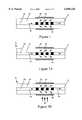
- FIG. 1is a schematic cross-sectional view of a fiber optic element showing a grating in the fiber core and external coating layer of the present invention
- FIGS. 2a and 2bare schematic cross-sectional view of a system including a fiber optic sensor incorporating the invention of FIG. 1;
- FIG. 3is a cross-sectional view of a tunable filter having a core grating surrounded by a driveable element having an electrically sensitive layer located between two electrodes electrically connected to a source of electric modulation;
- FIG. 4is a schematic cross-sectional view of a fiber optic element for cladding mode modulation showing a driveable element having an electrically sensitive layer mounted on the fiber;
- FIG. 5is a schematic cross-sectional view of a fiber optic element for wavelength--selective light modulation showing a first grating, a driveable element having an electrically sensitive layer as in FIG. 4 attached to the fiber, and a second grating;
- FIG. 6is a schematic cross-sectional view of a fiber optic filter that can independently select and modulate individual wavelengths, showing two tunable filters as in FIG. 3 with the cladding mode modulator of FIG. 4 located between them;
- FIG. 7is a schematic cross-sectional view of an electrically controlled modulator for a single wavelength including the tunable filter of FIG. 3 followed by a narrow-band reflection grating;
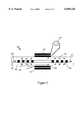
- FIG. 8is a schematic cross-sectional view of a tunable reflection filter showing a fiber optic device having two of the tunable filters of FIG. 3 with a lossy portion of the fiber core located between them and a broad-band reflection grating located downstream of the second tunable filter.
- the inventionis embodied in a fiber optic device providing a system and method for affecting the characteristic of a beam of light transmitted through an optical fiber.
- the inventioncontemplates a combination of at least one grating formed within the core of an optical fiber and a coating or layer formed, mounted on, or provided around an outer surface of a cladding layer of the optical fiber.
- the coating or layermay be positioned over the grating formed in the core of the optical fiber, or the coating or layer may be formed at a location along the fiber that is different from the location of the grating.
- one or more gratingsmay be combined with one or more coatings or layers, which may be positioned over all, some, or none of the gratings, depending on the functionality desired. More particularly, the invention contemplates various embodiments such as sensors, filters and modulators, among other devices, all of which may be constructed using the combination of at least one grating and coating or layer of the present invention. Where different embodiments have like elements, like reference numbers have been used.
- the inventiongenerally comprises an optical fiber 10 having a core 20 and cladding 30.
- a grating 40is formed in the core 20 and/or the cladding 30 to couple light into the cladding using methods well known to those skilled in the art.
- the grating 40is preferably a long-period grating, or rather, one in which the period is 20 microns or greater.
- the gratingmay be, for example, a refractive index grating, wherein light is refracted by either physical modulation, stress modulation, or other applicable techniques.
- a coating 50Positioned adjacent the grating 40, surrounding the outer circumference of the optical fiber 10, is a coating 50.
- the coating 50may be porous or non-porous, and may be formed from a polymer or any other material whose ability to transmit or reflect light is dependent upon a characteristic of the material that may be altered, or alternatively, the coating 50 may be formed from a material that is sensitive to an electrical or/and magnetic field such that application of a voltage or forming an electrical field in the material using suitable electrodes causes, for example, the index of refraction of the coating to change.
- the preferred thickness of the coatingis 0.5 micron to 200 microns, and may be a function of the desired operation of the optical device.
- the index of refraction of the core 20 and the cladding 30differ slightly so that when light is transmitted down the optical fiber 10 from a light source (not shown), almost all of the light remains in the core.
- the light encountering such a gratingis coupled by the grating into the cladding of the optical fiber.
- the addition of the coating 50 to the outside of the optical fiber 10results in a change in the light-guiding properties of the fiber, since the transmission of the light in the fiber is a function of the relationship between the refractive indices of the core, cladding and coating layer.
- the presence of the grating 40may establish a resonance for a particular wavelength of light in the core such that the particular wavelength of light is coupled from the core into the cladding.
- the resonance wavelengthis affected by the refractive index of the coating layer 50, so that changing the refractive index of the coating 50 alters the resonant wavelength of light that is coupled into the cladding.
- the refractive index of the coating layer 50is equal to or greater than the refractive index of the cladding, the light may be coupled into the coating itself where it can be acted upon or analyzed.
- One example of a device embodying the present inventionis a sensor comprising an optical fiber as described above surrounded by a polymer layer or coating that is sensitive to gamma radiation.
- an optical fiber incorporating a grating and polymer layeris positioned between a source of light having a wavelength of 1550 nanometers (nm), for example, a laser diode (not shown), and a light receiver such as a photo-diode (not shown).
- the refractive index of the polymer layer and the period of the gratingare selected so that a resonance within the fiber is established for the particular wavelength of 1550 nm, blocking the transmission of the light from the laser diode to the photodiode.
- the gamma radiationinteracts with the polymer layer, changing the refractive index of the polymer layer and shifting the wavelength of the resonance so that light from the laser diode at a wavelength of 1550 nm is now transmitted through the optical fiber to the photodiode, providing an indication that radiation is present.
- the intensity of the radiation at the position of the sensormay also be determined since the rate of the shift in refractive index of the polymer layer is dependent on the intensity of the radiation.
- the coating layermay be formed from a porous material so that gases or liquids from whatever ambient environment in which the sensor is placed may be incorporated into the layer through the well known process of diffusion. Depending on the types and levels of gas or liquid present, the refractive index or/and physical dimensions of the layer may change, affecting the resonance within the optical fiber and allowing the detection of gas or liquid.
- the coating layermay be sufficiently thin so that gases or liquids present in the ambient environment may partially dissolve the coating layer, affecting the resonance within the optical fiber and allowing the detection of the gas or liquid.
- the sensitive layer 50may also be formed in the cladding 30 of the fiber 10.
- the coating 50may be doped with optically sensitive molecules, for example, dyes.
- optically sensitive moleculesfor example, dyes.
- the dyes selected to dope the coatingmay be selected so that only particular wavelengths of light will cause the refractive index of the coating to change, thus forming a highly selective and sensitive optical filter, switch, or sensor.
- the above described inventionis particularly advantageous when embodied, as depicted in FIG. 3, as a tunable filter 100 incorporated into an optical fiber 110 in which a beam of light having multiple channels of information, typically separated by only small differences in wavelength, is transmitted.
- the various wavelengths of light 120 being transmitted through the optical fibermay be filtered to separate the channels of information according to the wavelength of the channel.
- an electro-sensitive layer 130such as poled poly(Disperse Red 1 methacrylate-co-methyl methacrylate) is formed or mounted between a pair of electrodes 140, 150, thus forming a driveable element 160. While single electrodes are shown in FIG.
- the preferred thickness (d) of the layer 130is approximately 0.1 to 10 microns.
- the element 160is formed on or mounted to the outer surface of the optical fiber 110 so that the element 160 overlays a fiber grating 170 formed in the core 180 of the optical fiber 110.
- the inner electrode 140that is, the electrode located between the electro-sensitive layer 130 and the cladding 190, must be sufficiently thin and/or optically transparent so that the light coupled into the cladding 190 by the grating 170 can effectively interact with the layer 130.
- the maximum sensitivity of the tuneable filter 100is achieved when the index of refraction of the cladding 190 and the layer 130 differ by less than 0.03 and the change ( ⁇ n) in the refractive index of the layer 130 caused by the voltage V is in the range of 10 -4 to 10 -3 .
- the resulting index change ⁇ n of the layer 130is approximately 10 -4 , which produces a change in the blocking wavelength of the filter 100 on the order of greater than 1 nanometer (nm).
- the material comprising the layer 130may be selected to provide either a rapid or a slow response to the application of the voltage V.
- the layer 130may include liquid crystals.
- the voltage V applied to the electrodes 140, 150 of the driveable element 160may be constant, or the voltage V may be changed over time by the driver 200.
- the tuneable filter 100 of the present inventionmay be dynamic and fast acting when the driveable element 160 includes a fast responding layer 130, such that the wavelength transmitted through the optical fiber 110 may be altered quickly.
- the tunable filter 100may be also be used as a switch to route the light signal along a path selected from a number of paths.
- a particular wavelength of the light 120may be coupled into the cladding 190, as shown by the arrows identified by reference numeral 210.
- the light 210 in the claddingmay either be altered, as described previously, or the light may simply be allowed to remain within the cladding 190.
- the present inventionalso includes embodiments, as depicted by a cladding mode modulator 220 shown in FIG. 4, where a driveable element 230, incorporating an electro-optically active layer 240 is positioned or mounted on the optical fiber 110 so that the driveable element 230 is not positioned over a grating.
- the positioning of the driveable element 230 in relation to a grating formed at some point within the fiber 110is dependent on the desired operation of the modulator 220.
- the element 230may be placed adjacent to a grating.
- light 250has been coupled into the cladding 190 of the fiber 110.
- the light 250 in the cladding 190is now transmitted through the portion of the cladding 190 that underlies the element 230 and may be affected as described above by application of a voltage V by driver 260 across electrodes 270, 280 of the driveable element 230, causing a change in the index of refraction of the layer 240, and thereby affecting the transmission of the light 250 through the cladding 190.
- a voltage Vby driver 260 across electrodes 270, 280 of the driveable element 230
- the light 250may be further coupled into the layer 240 itself, or it may remain within the cladding 190.
- the application of the voltage Vmay be varied over time, affecting the transmission of the light 250 in a periodic manner.
- a cladding mode modulator 220is in conjunction with a fiber laser (not shown) where beams of light coupled into the cladding 190 may be used to pump, or excite, molecules in the core 180 of the fiber 110 to produce laser light.
- the pumping beamsmay be modulated to effect a modulation of the laser beam produced in the core 180 of the fiber 110.
- the modulator 220may be used to control the pumping, and thus, the output of the fiber laser.
- the various embodiments of the present inventionmay be combined to provide a variety of optically active devices for controlling and/or modifying light passing through an optical fiber.
- Another example of such a device incorporating aspects of the present inventionis depicted by the wavelength-selective amplitude modulator 300 shown in FIG. 5.
- a fiber grating 310 formed in the core 320 of a fiber 330is used to couple light 340 of suitable resonance wavelength from the core 320 of the fiber 330 into the cladding 350 of the fiber 330.
- the coupled light 360then passes through a section of the cladding 350 surrounded by a driveable element 370 comprising an electro-optically active layer 380 formed or mounted between electrode layers 390, 400.
- the refractive index of the electro-optically active layer 380changes in accordance with the applied voltage V.
- This refractive index changeinteracts as described previously with the guiding properties, for example, the refractive index, of the cladding 350 of the optical fiber 330, affecting the light 360 transmitted through the cladding 350.
- a second grating 420may be located in the core 320 of the fiber 330 downstream of the driveable element 370 to couple any light 360 remaining in the cladding 350 back into the core 320 of the fiber 330.
- the devicemay be used as a wavelength, or channel, specific modulator for providing light 430 including optically encoded data to be transmitted further downstream in the fiber 330.
- the preferred distance between the grating 310 and the second grating 420is dependent on the wavelength of light that is desired to be modulated, but is typically less than 50 centimeters since transmission of light within the cladding 350 of the fiber 330 for extended distances results in a decrease in the amplitude of the transmitted light 360. It is also possible to couple only a portion of the light 340 from the core 320 of the fiber 330 into the cladding. When operated in this manner, the device operates as an interferometer.
- FIG. 6depicts a further example of the invention embodied in a fiber grating filter 500 having independently tunable attenuation and resonant wavelengths.
- This embodimentalso depicts how various aspects of the present invention can be combined to provide a variety of optically active devices for modulating, blocking or otherwise altering the light transmitted through an optical fiber.
- the fiber grating filter 500 depicted in FIG. 5includes the wavelength-selective amplitude modulator 400 of the FIG. 5. Accordingly, like elements in both Figures are identified using like reference numerals.
- the filter 500is assembled by adding two additional driveable elements 510, 520.
- Driveable element 510is positioned around grating 310 and includes a driveable optically active layer 530 formed or mounted between electrode layers 540, 550.
- driveable element 520is positioned around the second grating 420 and has a driveable optically active layer 560 formed or mounted between electrode layers 570, 580. Both driveable element 510 and driveable element 520 may be driven by signals provided by driver 590. The identical signals may be provided to both driveable elements 510 and 520 by driver 590, or signals may be provided to element 510 that are different from the signals provided to element 520 by driver 590. By manipulating the signals applied to the electrodes 540, 550 and 570, 580 the wavelength of light coupled into the cladding for processing by the cladding mode modulator depicted in FIG. 5 may be selectable, rather than fixed. Modulation of the signal may be provided by modulator 410 independently, as is depicted in FIG.
- a fixed reflection grating 610is formed in the core 620 of an optical fiber 630 downstream of the tunable grating 100 of the present invention as described above with reference to FIG. 3.
- the resonance wavelength of the tunable grating 100can be altered to match or not match the resonance wavelength of the fixed reflection grating 610.
- the resonance wavelength of the gratings 100, 610match no light is reflected at the resonance wavelengths and the light is transmitted through the core 620.
- This filter 600acts as a narrow-band modulator for light that is matched to the resonance of the reflection grating 610, and can be used to introduce a selected "delay" in the reflected light. This "delay" is particularly useful where it is necessary for light from two fibers of different length must arrive at a particular location having a predetermined time relationship. Alternatively, the filter 600 may assist in matching signals carried by different wavelengths of light within the same optical fiber.
- FIG. 8A further example of the broad application of the present invention is illustrated by the broadly tunable band pass reflection filter depicted in FIG. 8.
- two tunable gratings 710, 720 as described above with reference to FIG. 3are positioned along an optical fiber 730.
- a broadband Bragg grating 740is formed in the core 750 of the fiber 730 downstream of the tunable grating 720.
- the broadband Bragg grating 740may be constructed by, for example, decreasing the length of the grating 740 to approximately 1 millimeter (mm) or by making it chirped.
- a suitable broad-band blocking element 760is formed in the core 750 of the fiber 730 between the tunable gratings 710, 720 so that light cannot be transmitted between them through the core 750 of the fiber 730.
- This blocking element 760may be formed, for example, by intentionally damaging the core 750 of the fiber 730.
- the core 750may be altered in such a manner as to have a high loss, that is, adversely affect the amplitude of light transmitted through the core 750, at that location, or a grating may be formed in the core 750 that reflects or removes all of the transmitted light out of the core 750 of the optical fiber 730.
- This latter effectcan be achieved by forming another long-period grating (not shown) having a different period than the tunable gratings 710, 720.
- light at the resonance wavelength of tunable grating 710is deflected into the cladding 770 where it is transmitted through the cladding 770 past the blocking element 760 and then is returned to the core 750 by the second tunable grating 720, which is tuned to the same resonant wavelength as tunable grating 710.
- the lightthen continues through the core 750 where it encounters the broadband Bragg grating 740, which reflects the light back along its original path, through grating 720 and into the cladding 770 until the light is again returned into to the core 750 by tunable grating 710, whereby the light is then propagated upstream through the optical fiber 730 towards its source.
- the resonance wavelength of the tunable gratings 710, 720in tandem, the wavelength of light that is reflected by the device can be altered.
- the Bragg reflection grating 740may be chirped.
- the gratingis formed so that it has several regions, with each region having different resonant wavelengths. Because it has different resonant wavelengths located at different locations along the optical fiber 730, the chirped grating imparts different optical delays to different wavelengths.
- the gratings 710, 720may be tuned to provide a variable delay line which is useful for phased array antennas.
- the system of the inventionprovides a way of altering the characteristics of light transmitted through an optical fiber to enhance the transmission of data through the fiber. Further, the system accomplishes this without costly modification or polishing of the optical fiber. Moreover, the system provides a controllable method of selectively coupling wavelengths of light from the core of the fiber into the cladding of the fiber without bending the fiber, which prevents damage to the fiber due to the strain of bending.
- the system of the present inventionmay be easily and inexpensively added to existing fiber optic cables using known techniques, and thus provides for improved reliability and control of the light, and thus the data, transmitted through the optical fiber.
Landscapes
- Physics & Mathematics (AREA)
- General Physics & Mathematics (AREA)
- Optics & Photonics (AREA)
- Nonlinear Science (AREA)
- Optical Modulation, Optical Deflection, Nonlinear Optics, Optical Demodulation, Optical Logic Elements (AREA)
Abstract
Description
Δn=-1/2n.sup.3 rE
Claims (52)
Priority Applications (1)
| Application Number | Priority Date | Filing Date | Title |
|---|---|---|---|
| US08/957,153US6058226A (en) | 1997-10-24 | 1997-10-24 | Optical fiber sensors, tunable filters and modulators using long-period gratings |
Applications Claiming Priority (1)
| Application Number | Priority Date | Filing Date | Title |
|---|---|---|---|
| US08/957,153US6058226A (en) | 1997-10-24 | 1997-10-24 | Optical fiber sensors, tunable filters and modulators using long-period gratings |
Publications (1)
| Publication Number | Publication Date |
|---|---|
| US6058226Atrue US6058226A (en) | 2000-05-02 |
Family
ID=25499156
Family Applications (1)
| Application Number | Title | Priority Date | Filing Date |
|---|---|---|---|
| US08/957,153Expired - Fee RelatedUS6058226A (en) | 1997-10-24 | 1997-10-24 | Optical fiber sensors, tunable filters and modulators using long-period gratings |
Country Status (1)
| Country | Link |
|---|---|
| US (1) | US6058226A (en) |
Cited By (90)
| Publication number | Priority date | Publication date | Assignee | Title |
|---|---|---|---|---|
| US6181840B1 (en)* | 1999-06-25 | 2001-01-30 | National Science Council | Reflectivity-tunable fiber optic reflector |
| US6192177B1 (en)* | 1998-07-17 | 2001-02-20 | Lucent Technologies Inc. | Electrically modifiable optical grating devices |
| US6198868B1 (en)* | 1999-03-12 | 2001-03-06 | Samsung Electronics Co., Ltd. | Temperature compensated long period optical fiber grating filter |
| WO2000070307A3 (en)* | 1999-05-12 | 2001-03-08 | Joerg Huebner | A sensor and a method for determining the direction and the amplitude of a bend |
| US6285812B1 (en)* | 1998-07-17 | 2001-09-04 | Lucent Technologies Inc. | Switchable and reconfigurable optical grating devices and methods for making them |
| US20010043772A1 (en)* | 1997-06-06 | 2001-11-22 | Sorin Wayne V. | Methods and apparatus for measuring the power spectrum of optical signals |
| EP1156607A3 (en)* | 2000-05-18 | 2002-01-30 | Marconi Communications Limited | Radiation power equalizer |
| JP2002510065A (en)* | 1998-03-30 | 2002-04-02 | コーニング・インコーポレーテッド | Variable optical fiber, Bragg, long period grating |
| WO2002027358A1 (en)* | 2000-09-27 | 2002-04-04 | The Regents Of The University Of California | Method for optical modulation at periodic optical structure band edges |
| US6385368B1 (en)* | 1998-02-20 | 2002-05-07 | Lucent Technologies, Inc. | Method and apparatus for modulating signal strength within optical systems |
| WO2002049252A1 (en)* | 2000-12-15 | 2002-06-20 | Elematics, Inc. | High-speed optical data network with improved optical receiver |
| US6411755B1 (en)* | 2000-04-27 | 2002-06-25 | University Of Rochester | Cladding-assisted single-mode fiber coupler |
| WO2001090805A3 (en)* | 2000-05-23 | 2002-08-22 | Novera Optics Inc | Tunable filter with core mode blocker |
| EP1243949A1 (en)* | 2001-03-14 | 2002-09-25 | Alcatel | Optical filter device, method for tuning and communication system |
| WO2002084360A1 (en)* | 2000-03-06 | 2002-10-24 | The Penn State Research Foundation | Single resonant band, tunable optical fiber wavelength filter based on long-period fiber crating |
| US6490391B1 (en) | 2000-07-12 | 2002-12-03 | Oluma, Inc. | Devices based on fibers engaged to substrates with grooves |
| US6496303B1 (en)* | 1998-03-04 | 2002-12-17 | The University Of Sydney | Ultra-broadband low-noise gain-flattened rare-earth-doped fibre amplifier |
| US6501875B2 (en) | 2000-06-27 | 2002-12-31 | Oluma, Inc. | Mach-Zehnder inteferometers and applications based on evanescent coupling through side-polished fiber coupling ports |
| US20030002795A1 (en)* | 2001-07-02 | 2003-01-02 | Norman Fisher | Fiber bragg grating fabrication method |
| US20030002794A1 (en)* | 2001-06-27 | 2003-01-02 | Siddharth Ramachandran | Optical bandpass filter using long period gratings |
| US6516114B2 (en) | 2000-06-27 | 2003-02-04 | Oluma, Inc. | Integration of fibers on substrates fabricated with grooves |
| US6519388B1 (en)* | 1998-12-04 | 2003-02-11 | Cidra Corporation | Tube-encased fiber grating |
| US6522810B2 (en)* | 2000-10-31 | 2003-02-18 | Sumitomo Electric Industries, Ltd. | Optical loss filter |
| US6529676B2 (en) | 2000-12-08 | 2003-03-04 | Lucent Technologies Inc. | Waveguide incorporating tunable scattering material |
| US6542663B1 (en) | 2000-09-07 | 2003-04-01 | Oluma, Inc. | Coupling control in side-polished fiber devices |
| WO2002016979A3 (en)* | 2000-08-24 | 2003-04-17 | Sabeus Photonics Inc | Fiberoptic bus, modulator, detector and emitter using cladding mode coupling |
| US20030091286A1 (en)* | 2001-11-12 | 2003-05-15 | Alcatel | Tunable optical device and optical system using the tunable optical device as coding filter |
| US6571035B1 (en) | 2000-08-10 | 2003-05-27 | Oluma, Inc. | Fiber optical switches based on optical evanescent coupling between two fibers |
| WO2003044591A1 (en)* | 2001-11-19 | 2003-05-30 | Optiva, Inc. | Electrooptical devices, electrooptical thin crystal films and methods making same |
| US20030103708A1 (en)* | 2001-11-30 | 2003-06-05 | Photintech Inc. | In-guide control of optical propagation |
| US6597833B1 (en) | 2000-06-27 | 2003-07-22 | Oluma, Inc. | Wavelength-division multiplexers and demultiplexers based on mach-zehnder interferometers and evanescent coupling |
| US6621952B1 (en) | 2000-08-10 | 2003-09-16 | Oluma, Inc. | In-fiber variable optical attenuators and modulators using index-changing liquid media |
| US6621951B1 (en) | 2000-06-27 | 2003-09-16 | Oluma, Inc. | Thin film structures in devices with a fiber on a substrate |
| US6625349B2 (en) | 2000-06-27 | 2003-09-23 | Oluma, Inc. | Evanescent optical coupling between a waveguide formed on a substrate and a side-polished fiber |
| US20030194182A1 (en)* | 2002-04-15 | 2003-10-16 | Alcatel | Dynamic gain equalising filter |
| US6650810B1 (en)* | 2000-08-15 | 2003-11-18 | Physical Optics Corporation | Tunable filter |
| US20030215185A1 (en)* | 1999-12-06 | 2003-11-20 | Cidra Corporation, | Large diameter optical waveguide having long period grating therein |
| WO2003025639A3 (en)* | 2001-09-19 | 2003-11-27 | Univ Cranfield | Optical transmission device having a long period grating and an overcladding |
| WO2002052321A3 (en)* | 2000-12-22 | 2003-12-18 | Schleifring Und Appbau Gmbh | Device for the transmission of optical signals by means of planar light guides |
| KR100415712B1 (en)* | 2001-10-11 | 2004-01-24 | 학교법인 성균관대학 | Transmissive mode-coupling system based on grating pairs |
| US20040017991A1 (en)* | 2002-02-22 | 2004-01-29 | Bookham Technology Limited | Refractive index control |
| KR100417468B1 (en)* | 2001-05-04 | 2004-02-05 | 송재원 | Method of manufacturing cladding optical fiber amplifier using long-period fiber grating pair |
| US6697541B1 (en) | 1999-05-17 | 2004-02-24 | Corning Incorporated | Amplitude tunable filter |
| US20040056183A1 (en)* | 2002-09-24 | 2004-03-25 | Eggleton Benjamin J. | Wavelength monitoring optical fibers using detection in the near field |
| US20040071400A1 (en)* | 2000-04-11 | 2004-04-15 | Karim Haroud | Fibre laser sensor |
| US6741189B1 (en)* | 1999-10-06 | 2004-05-25 | Microsoft Corporation | Keypad having optical waveguides |
| US6744948B1 (en) | 2001-06-20 | 2004-06-01 | Oluma, Inc. | Fiber tap monitor based on evanescent coupling |
| FR2848678A1 (en)* | 2002-12-16 | 2004-06-18 | Teem Photonics | Waveguide optical signal sampler includes waveguide with section of core coupled to sleeve to extract sample of transmitted signal |
| US20040151434A1 (en)* | 2002-09-10 | 2004-08-05 | Photintech Inc. | Method and apparatus for channel selective control of light propagation in an optical waveguide |
| KR100448106B1 (en)* | 2002-10-16 | 2004-09-08 | 광주과학기술원 | A novel core mode blocker based on a hollow optical fiber |
| US20040190812A1 (en)* | 2001-10-05 | 2004-09-30 | Barger Lee Allen | Refractive index probe apparatus and system |
| US20040218847A1 (en)* | 2003-03-19 | 2004-11-04 | Luna Innovations, Inc. | Fiber-optic apparatus and method for making simultaneous multiple parameter measurements |
| KR100460203B1 (en)* | 2002-06-25 | 2004-12-08 | 경북대학교 산학협력단 | Signal light Pumping Method using Long-period fiber grating for Cladding pump fiber amplifier |
| US6832023B1 (en) | 2000-05-19 | 2004-12-14 | Georgia Tech Research Corporation | Optical fiber gratings with azimuthal refractive index perturbation, method of fabrication, and devices for tuning, attenuating, switching, and modulating optical signals |
| US20040258358A1 (en)* | 2001-11-15 | 2004-12-23 | Duguay Michel A | Segmented waveguide array grating filters |
| US6850655B2 (en) | 1997-06-16 | 2005-02-01 | Novera Optics, Inc. | Optical apparatus with faraday rotator, static gain flattening filter and variable optical attenuator |
| WO2005017587A1 (en)* | 2003-08-14 | 2005-02-24 | Technische Universität Dresden | Fiber optic filter device |
| KR100492874B1 (en)* | 2002-10-16 | 2005-06-02 | 광주과학기술원 | A novel core mode blocker and menufacturing method thereof |
| US20050191007A1 (en)* | 2001-03-29 | 2005-09-01 | Sabeus Photonics, Inc. | Mode coupling devices with complex spectral profile |
| US6956982B1 (en)* | 1998-04-20 | 2005-10-18 | Universiteit Twente | Integrated optical lightguide device |
| EP1596243A1 (en)* | 2004-05-15 | 2005-11-16 | LG Electronics Inc. | Optical true-time delay apparatus and manufacturing method thereof |
| US20050267326A1 (en)* | 2001-10-02 | 2005-12-01 | Alfred E. Mann Institute For Biomedical Eng. At The University Of Southern California | Percutaneous chemical sensor based on fluorescence resonant energy transfer (FRET) |
| US20050269490A1 (en)* | 2004-06-04 | 2005-12-08 | Hans-Peter Loock | Long period grating sensor methods and apparatus |
| US6993224B1 (en) | 2001-11-15 | 2006-01-31 | UNIVERSITé LAVAL | Segmented waveguide array gratings (SWAG)-based archival optical memory |
| US20060126991A1 (en)* | 2004-12-13 | 2006-06-15 | Haiying Huang | In-fiber whitelight interferometry using long-period fiber grating |
| US7096053B2 (en) | 2001-10-02 | 2006-08-22 | Alfred E. Mann Institute For Biomedical Engineering At The University Of Southern California | Internal biochemical sensing device |
| US20070010726A1 (en)* | 2002-10-02 | 2007-01-11 | Alfred E. Mann Inst. For Biomedical Engineering At The University Of Southern California | Internal biochemical sensing device |
| US20070069893A1 (en)* | 2005-03-04 | 2007-03-29 | Compudyne Corporation | Polarization-based sensor for secure fiber optic network and other security applications |
| US20070096007A1 (en)* | 2005-08-29 | 2007-05-03 | Compudyne Corporation | Distributed fiber optic sensor with location capability |
| DE102005056225A1 (en)* | 2005-11-25 | 2007-05-31 | Petter, Jürgen, , Dr. | Electro optically tunable sensor e.g. biochemical sensor, for detecting e.g. pressure of e.g. liquid, has optical transverse electromagnetic wave, whose core stands in reciprocal effect with electro optically tunable substrate material |
| US20070258673A1 (en)* | 2006-05-08 | 2007-11-08 | El-Sherif Mahmoud A | On-fiber tunable bragg gratings for DWDM applications |
| US20080129980A1 (en)* | 2006-11-30 | 2008-06-05 | North Carolina State University | In-line fiber optic sensor devices and methods of fabricating same |
| US20080144992A1 (en)* | 2006-07-19 | 2008-06-19 | Fiber Sensys Llc | Fiber-optic mat sensor |
| US20080192780A1 (en)* | 2007-02-13 | 2008-08-14 | Fei Luo | Q-switched all-fibre laser |
| KR100855827B1 (en) | 2007-01-24 | 2008-09-01 | 광주과학기술원 | All-optical fiber interferometer and method of manufacturing same |
| CN100458406C (en)* | 2005-07-01 | 2009-02-04 | 重庆工学院 | MZ interference SPR chemical and biological sensor and system with fibre-optical microstructure |
| US20090080898A1 (en)* | 2007-09-24 | 2009-03-26 | Fiber Sensys Llc | Method and apparatus for reducing noise in a fiber-optic sensor |
| US20100150494A1 (en)* | 2008-12-16 | 2010-06-17 | Cogo Optronics, Inc. | Monolithic optoelectronic twe-component structure for high frequencies and low optical insertion loss |
| EP1884764A4 (en)* | 2005-05-26 | 2011-03-23 | Mitsubishi Electric Corp | FIBER OPTIC SENSOR |
| US7970245B2 (en)* | 2007-07-18 | 2011-06-28 | Sungkyunkwan University Foundation For Corporate Collaboration | Optical biosensor using SPR phenomenon |
| US20110275899A1 (en)* | 2000-11-10 | 2011-11-10 | The General Hospital Corporation | Spectrally encoded miniature endoscopic imaging probe |
| US9190800B2 (en)* | 2007-02-13 | 2015-11-17 | Fei Luo | Q-switched all-fiber laser |
| US9240262B1 (en) | 2014-07-21 | 2016-01-19 | General Electric Company | Systems and methods for distributed pressure sensing |
| US9341532B2 (en) | 2014-03-24 | 2016-05-17 | General Electric Company | Systems and methods for distributed pressure sensing |
| US9857290B2 (en)* | 2006-10-25 | 2018-01-02 | Weatherford Canada Ltd. | Tilted grating sensor |
| US10324316B2 (en)* | 2017-08-21 | 2019-06-18 | Luna Innovations Incorporated | Security switch |
| US10852478B1 (en) | 2019-05-28 | 2020-12-01 | Ciena Corporation | Monolithically integrated gain element |
| CN112033539A (en)* | 2020-08-17 | 2020-12-04 | 桂林电子科技大学 | Novel transmission type fiber grating spectrometer |
| US20220171105A1 (en)* | 2020-09-11 | 2022-06-02 | Board Of Regents, The University Of Texas System | Resonant filters having simultaneously tuned central wavelengths and sidebands |
| US20220349819A1 (en)* | 2019-07-17 | 2022-11-03 | Universitat Politècnica De València | Diffractive device for chemical and biological analysis |
Citations (14)
| Publication number | Priority date | Publication date | Assignee | Title |
|---|---|---|---|---|
| US4996419A (en)* | 1989-12-26 | 1991-02-26 | United Technologies Corporation | Distributed multiplexed optical fiber Bragg grating sensor arrangeement |
| US5007705A (en)* | 1989-12-26 | 1991-04-16 | United Technologies Corporation | Variable optical fiber Bragg filter arrangement |
| US5430817A (en)* | 1994-03-31 | 1995-07-04 | At&T Corp. | Optical systems and devices using long period spectral shaping devices |
| US5550940A (en)* | 1995-02-24 | 1996-08-27 | Lucent Technologies Inc. | Optical tapping filters employing long period gratings |
| US5579143A (en)* | 1993-06-04 | 1996-11-26 | Ciena Corporation | Optical system with tunable in-fiber gratings |
| US5641956A (en)* | 1996-02-02 | 1997-06-24 | F&S, Inc. | Optical waveguide sensor arrangement having guided modes-non guided modes grating coupler |
| US5647039A (en)* | 1995-12-14 | 1997-07-08 | Lucent Technologies Inc. | Optical switching system and devices using a long period grating |
| US5668821A (en)* | 1996-01-16 | 1997-09-16 | Lucent Technologies Inc. | Optical systems and devices employing spectrally flattened amplified spontaneous emission |
| US5767411A (en)* | 1996-12-31 | 1998-06-16 | Cidra Corporation | Apparatus for enhancing strain in intrinsic fiber optic sensors and packaging same for harsh environments |
| US5841920A (en)* | 1997-03-18 | 1998-11-24 | Lucent Technologies Inc. | Fiber grating package |
| US5864641A (en)* | 1997-04-11 | 1999-01-26 | F&S, Inc. | Optical fiber long period sensor having a reactive coating |
| US5999671A (en)* | 1997-10-27 | 1999-12-07 | Lucent Technologies Inc. | Tunable long-period optical grating device and optical systems employing same |
| US6011866A (en)* | 1995-05-22 | 2000-01-04 | Canon Kabushiki Kaisha | Template formation method and apparatus |
| US6011881A (en)* | 1997-12-29 | 2000-01-04 | Ifos, Intelligent Fiber Optic Systems | Fiber-optic tunable filter |
- 1997
- 1997-10-24USUS08/957,153patent/US6058226A/ennot_activeExpired - Fee Related
Patent Citations (14)
| Publication number | Priority date | Publication date | Assignee | Title |
|---|---|---|---|---|
| US4996419A (en)* | 1989-12-26 | 1991-02-26 | United Technologies Corporation | Distributed multiplexed optical fiber Bragg grating sensor arrangeement |
| US5007705A (en)* | 1989-12-26 | 1991-04-16 | United Technologies Corporation | Variable optical fiber Bragg filter arrangement |
| US5579143A (en)* | 1993-06-04 | 1996-11-26 | Ciena Corporation | Optical system with tunable in-fiber gratings |
| US5430817A (en)* | 1994-03-31 | 1995-07-04 | At&T Corp. | Optical systems and devices using long period spectral shaping devices |
| US5550940A (en)* | 1995-02-24 | 1996-08-27 | Lucent Technologies Inc. | Optical tapping filters employing long period gratings |
| US6011866A (en)* | 1995-05-22 | 2000-01-04 | Canon Kabushiki Kaisha | Template formation method and apparatus |
| US5647039A (en)* | 1995-12-14 | 1997-07-08 | Lucent Technologies Inc. | Optical switching system and devices using a long period grating |
| US5668821A (en)* | 1996-01-16 | 1997-09-16 | Lucent Technologies Inc. | Optical systems and devices employing spectrally flattened amplified spontaneous emission |
| US5641956A (en)* | 1996-02-02 | 1997-06-24 | F&S, Inc. | Optical waveguide sensor arrangement having guided modes-non guided modes grating coupler |
| US5767411A (en)* | 1996-12-31 | 1998-06-16 | Cidra Corporation | Apparatus for enhancing strain in intrinsic fiber optic sensors and packaging same for harsh environments |
| US5841920A (en)* | 1997-03-18 | 1998-11-24 | Lucent Technologies Inc. | Fiber grating package |
| US5864641A (en)* | 1997-04-11 | 1999-01-26 | F&S, Inc. | Optical fiber long period sensor having a reactive coating |
| US5999671A (en)* | 1997-10-27 | 1999-12-07 | Lucent Technologies Inc. | Tunable long-period optical grating device and optical systems employing same |
| US6011881A (en)* | 1997-12-29 | 2000-01-04 | Ifos, Intelligent Fiber Optic Systems | Fiber-optic tunable filter |
Non-Patent Citations (42)
| Title |
|---|
| Arce Diego et al., Fiber Bragg grationg as an optical filter tuned by a magnetic field, Optics Letters, vol. 22, No. 9, May 1, 1997, pp. 603 605.* |
| Arce-Diego et al., "Fiber Bragg grationg as an optical filter tuned by a magnetic field," Optics Letters, vol. 22, No. 9, May 1, 1997, pp. 603-605. |
| Bhatia et al., "Optical fiber long-period grating sensors," Optics Letter, vol. 21, No. 9, May 1, 1996, pp. 692-694. |
| Bhatia et al., "Optical Fiber Long-Period Grating Sensors," Technical Update (Undated). |
| Bhatia et al., Optical fiber long period grating sensors, Optics Letter, vol. 21, No. 9, May 1, 1996, pp. 692 694.* |
| Bhatia et al., Optical Fiber Long Period Grating Sensors, Technical Update (Undated).* |
| Cruz et al., "Fiber Bragg gratings tuned and chirped using magnetic fields," Electron. Lett. vol. 33, No. 3, Jan. 30, 1997, pp. 235-237. |
| Cruz et al., Fiber Bragg gratings tuned and chirped using magnetic fields, Electron. Lett. vol. 33, No. 3, Jan. 30, 1997, pp. 235 237.* |
| Devaux et al., "InGaAsP/InGaAsP/InAsP MQW polarization-independent modulator with high optical power saturation," OFC'97 Tech. Digest, 139 (1997). |
| Devaux et al., InGaAsP/InGaAsP/InAsP MQW polarization independent modulator with high optical power saturation, OFC 97 Tech. Digest, 139 (1997).* |
| Dianov et al., "In-fiber Mach-Zhender Interferometer Based On A Pair Of Long-Period Gratings," Proc. 22 European Conference on Optical Communication ECOC'96, 1, 65 (1996). |
| Dianov et al., "Photoinduced Long-Period Fiber Grating As A Promising Sensor Element," (Article Undated). |
| Dianov et al., In fiber Mach Zhender Interferometer Based On A Pair Of Long Period Gratings, Proc. 22 European Conference on Optical Communication ECOC 96, 1, 65 (1996).* |
| Dianov et al., Photoinduced Long Period Fiber Grating As A Promising Sensor Element, (Article Undated).* |
| Erdogan et al., "Fiber phase gratings reflect advances in lightwave technology," Laser focus World, Feb. 1994, pp. 73-80. |
| Erdogan et al., Fiber phase gratings reflect advances in lightwave technology, Laser focus World, Feb. 1994, pp. 73 80.* |
| Hamilton et al., "High brandwidth traveling wave polymeric in-line fiber modulator," CLEO'97 Tech. Digest, May 1997, p. 293. |
| Hamilton et al., High brandwidth traveling wave polymeric in line fiber modulator, CLEO 97 Tech. Digest, May 1997, p. 293.* |
| Hill et al., "Polymeric in-line fiber modulator using novel processing techniques," OFC '96 Tech. Digest, Conf. Feb.-Mar. 1996, pp. 166-167. |
| Hill et al., Polymeric in line fiber modulator using novel processing techniques, OFC 96 Tech. Digest, Conf. Feb. Mar. 1996, pp. 166 167.* |
| Juma, "Bragg gratings boost data transmission rates," Reprinted from Laser Focus World, Nov. 1996. |
| Juma, "Fiber Bragg Gratings: Ready To Drive Markets," Lasers & Optronics, May 1996, pp. 41-44. |
| Juma, Bragg gratings boost data transmission rates, Reprinted from Laser Focus World, Nov. 1996.* |
| Juma, Fiber Bragg Gratings: Ready To Drive Markets, Lasers & Optronics, May 1996, pp. 41 44.* |
| Kashyap, "Photosensitive Optical Fibers: Devices and Applications," Optical Fiber Technology 1, 17-34 (1994), pp. 17-34. |
| Kashyap, Photosensitive Optical Fibers: Devices and Applications, Optical Fiber Technology 1, 17 34 (1994), pp. 17 34.* |
| Kokx, "Bragg Today," vol. 1, Issue 1, Fall 1996, pp. 1-4. |
| Kokx, Bragg Today, vol. 1, Issue 1, Fall 1996, pp. 1 4.* |
| Mauchline et al. "Low voltage tunable in-line channel dropping filter using liquid crystal waveguide overlays," Electron. Lett. vol. 33, No. 11, May 22, 1997, pp. 985-986. |
| Mauchline et al. Low voltage tunable in line channel dropping filter using liquid crystal waveguide overlays, Electron. Lett. vol. 33, No. 11, May 22, 1997, pp. 985 986.* |
| Morante et al., "New micro-optic cell optic fibre gas sensors with interferometric noise reduction," Electron. Lett. vol. 33, No. 16, Jul. 31, 1997, pp. 1407-1409. |
| Morante et al., New micro optic cell optic fibre gas sensors with interferometric noise reduction, Electron. Lett. vol. 33, No. 16, Jul. 31, 1997, pp. 1407 1409.* |
| Nagamura et al., "Novel all optical light modulation based on complex refractive index changes of organic dye-doped polymer film upon photoexcitation," Appl. Phys. Lett., vol. 69 No. 9, Aug. 195, pp. 1191-1193. |
| Nagamura et al., Novel all optical light modulation based on complex refractive index changes of organic dye doped polymer film upon photoexcitation, Appl. Phys. Lett., vol. 69 No. 9, Aug. 195, pp. 1191 1193.* |
| St J Russell et al., "Fibre gratings," Physics Word, Oct. 1993, pp. 41-46. |
| St J Russell et al., Fibre gratings, Physics Word, Oct. 1993, pp. 41 46.* |
| Vasiliev et al., "Postfabrication resonance peak positioning of long-period cladding-mode-coupled gratings," Optics Letters, vol. 21, No. 22, Nov. 15, 1996, pp. 1830-1832. |
| Vasiliev et al., Postfabrication resonance peak positioning of long period cladding mode coupled gratings, Optics Letters, vol. 21, No. 22, Nov. 15, 1996, pp. 1830 1832.* |
| Vengsarkar et al., "Long-period Fiber Gratings s Band-Rejection Filters," Journal of Lightwave Technology, vol. 14, No. 1, Jan. 1996, pp. 58-65. |
| Vengsarkar et al., Long period Fiber Gratings s Band Rejection Filters, Journal of Lightwave Technology, vol. 14, No. 1, Jan. 1996, pp. 58 65.* |
| Xu et al., "Turnable fibre bandpass filter based on a linearly chirped Bragg grating for wavelength demultiplexing," Electron. Lett. vol. 32, No. 20, Sep. 26, 1996, pp. 1918-1919. |
| Xu et al., Turnable fibre bandpass filter based on a linearly chirped Bragg grating for wavelength demultiplexing, Electron. Lett. vol. 32, No. 20, Sep. 26, 1996, pp. 1918 1919.* |
Cited By (139)
| Publication number | Priority date | Publication date | Assignee | Title |
|---|---|---|---|---|
| US6801686B2 (en) | 1997-06-06 | 2004-10-05 | Novera Optics, Inc. | Methods and apparatus for measuring the power spectrum of optical signals |
| US20010043772A1 (en)* | 1997-06-06 | 2001-11-22 | Sorin Wayne V. | Methods and apparatus for measuring the power spectrum of optical signals |
| US6850655B2 (en) | 1997-06-16 | 2005-02-01 | Novera Optics, Inc. | Optical apparatus with faraday rotator, static gain flattening filter and variable optical attenuator |
| US6385368B1 (en)* | 1998-02-20 | 2002-05-07 | Lucent Technologies, Inc. | Method and apparatus for modulating signal strength within optical systems |
| US6496303B1 (en)* | 1998-03-04 | 2002-12-17 | The University Of Sydney | Ultra-broadband low-noise gain-flattened rare-earth-doped fibre amplifier |
| US6498877B1 (en)* | 1998-03-30 | 2002-12-24 | Corning Incorporated | Tunable optical fiber bragg and long period grating |
| JP2002510065A (en)* | 1998-03-30 | 2002-04-02 | コーニング・インコーポレーテッド | Variable optical fiber, Bragg, long period grating |
| US6956982B1 (en)* | 1998-04-20 | 2005-10-18 | Universiteit Twente | Integrated optical lightguide device |
| US6192177B1 (en)* | 1998-07-17 | 2001-02-20 | Lucent Technologies Inc. | Electrically modifiable optical grating devices |
| US6285812B1 (en)* | 1998-07-17 | 2001-09-04 | Lucent Technologies Inc. | Switchable and reconfigurable optical grating devices and methods for making them |
| US6519388B1 (en)* | 1998-12-04 | 2003-02-11 | Cidra Corporation | Tube-encased fiber grating |
| US6198868B1 (en)* | 1999-03-12 | 2001-03-06 | Samsung Electronics Co., Ltd. | Temperature compensated long period optical fiber grating filter |
| WO2000070307A3 (en)* | 1999-05-12 | 2001-03-08 | Joerg Huebner | A sensor and a method for determining the direction and the amplitude of a bend |
| US6697541B1 (en) | 1999-05-17 | 2004-02-24 | Corning Incorporated | Amplitude tunable filter |
| US6181840B1 (en)* | 1999-06-25 | 2001-01-30 | National Science Council | Reflectivity-tunable fiber optic reflector |
| US6741189B1 (en)* | 1999-10-06 | 2004-05-25 | Microsoft Corporation | Keypad having optical waveguides |
| US20030215185A1 (en)* | 1999-12-06 | 2003-11-20 | Cidra Corporation, | Large diameter optical waveguide having long period grating therein |
| WO2002084360A1 (en)* | 2000-03-06 | 2002-10-24 | The Penn State Research Foundation | Single resonant band, tunable optical fiber wavelength filter based on long-period fiber crating |
| US6563985B2 (en)* | 2000-03-06 | 2003-05-13 | The Penn State Research Foundation | Single resonant band, tunable optical fiber wavelength filter based on long-period fiber grating |
| US20040071400A1 (en)* | 2000-04-11 | 2004-04-15 | Karim Haroud | Fibre laser sensor |
| US6901187B2 (en)* | 2000-04-11 | 2005-05-31 | Vetco Gray Controls Limited | Fiber laser sensor |
| US6411755B1 (en)* | 2000-04-27 | 2002-06-25 | University Of Rochester | Cladding-assisted single-mode fiber coupler |
| CN100375416C (en)* | 2000-05-18 | 2008-03-12 | 爱立信股份有限公司 | Add/drop multiplexer and equalization method for wavelength division multiplexing optical communication system |
| US6697188B2 (en) | 2000-05-18 | 2004-02-24 | Marconi Communications Limited | Radiation power equalizer |
| EP1156607A3 (en)* | 2000-05-18 | 2002-01-30 | Marconi Communications Limited | Radiation power equalizer |
| US6832023B1 (en) | 2000-05-19 | 2004-12-14 | Georgia Tech Research Corporation | Optical fiber gratings with azimuthal refractive index perturbation, method of fabrication, and devices for tuning, attenuating, switching, and modulating optical signals |
| WO2001090805A3 (en)* | 2000-05-23 | 2002-08-22 | Novera Optics Inc | Tunable filter with core mode blocker |
| US6501875B2 (en) | 2000-06-27 | 2002-12-31 | Oluma, Inc. | Mach-Zehnder inteferometers and applications based on evanescent coupling through side-polished fiber coupling ports |
| US6625349B2 (en) | 2000-06-27 | 2003-09-23 | Oluma, Inc. | Evanescent optical coupling between a waveguide formed on a substrate and a side-polished fiber |
| US6621951B1 (en) | 2000-06-27 | 2003-09-16 | Oluma, Inc. | Thin film structures in devices with a fiber on a substrate |
| US6556746B1 (en) | 2000-06-27 | 2003-04-29 | Oluma, Inc. | Integrated fiber devices based on Mach-Zehnder interferometers and evanescent optical coupling |
| US6597833B1 (en) | 2000-06-27 | 2003-07-22 | Oluma, Inc. | Wavelength-division multiplexers and demultiplexers based on mach-zehnder interferometers and evanescent coupling |
| US6516114B2 (en) | 2000-06-27 | 2003-02-04 | Oluma, Inc. | Integration of fibers on substrates fabricated with grooves |
| US6690857B2 (en) | 2000-07-12 | 2004-02-10 | Oluma, Inc. | Fiber devices having side evanescent coupling port |
| US6490391B1 (en) | 2000-07-12 | 2002-12-03 | Oluma, Inc. | Devices based on fibers engaged to substrates with grooves |
| US6571035B1 (en) | 2000-08-10 | 2003-05-27 | Oluma, Inc. | Fiber optical switches based on optical evanescent coupling between two fibers |
| US6621952B1 (en) | 2000-08-10 | 2003-09-16 | Oluma, Inc. | In-fiber variable optical attenuators and modulators using index-changing liquid media |
| US6650810B1 (en)* | 2000-08-15 | 2003-11-18 | Physical Optics Corporation | Tunable filter |
| WO2002016979A3 (en)* | 2000-08-24 | 2003-04-17 | Sabeus Photonics Inc | Fiberoptic bus, modulator, detector and emitter using cladding mode coupling |
| US6542663B1 (en) | 2000-09-07 | 2003-04-01 | Oluma, Inc. | Coupling control in side-polished fiber devices |
| WO2002027358A1 (en)* | 2000-09-27 | 2002-04-04 | The Regents Of The University Of California | Method for optical modulation at periodic optical structure band edges |
| US6522810B2 (en)* | 2000-10-31 | 2003-02-18 | Sumitomo Electric Industries, Ltd. | Optical loss filter |
| US20110275899A1 (en)* | 2000-11-10 | 2011-11-10 | The General Hospital Corporation | Spectrally encoded miniature endoscopic imaging probe |
| US6529676B2 (en) | 2000-12-08 | 2003-03-04 | Lucent Technologies Inc. | Waveguide incorporating tunable scattering material |
| WO2002049252A1 (en)* | 2000-12-15 | 2002-06-20 | Elematics, Inc. | High-speed optical data network with improved optical receiver |
| US20080107378A9 (en)* | 2000-12-22 | 2008-05-08 | Harry Schilling | Device for transferring optical signals by means of planar optical conductors |
| WO2002052321A3 (en)* | 2000-12-22 | 2003-12-18 | Schleifring Und Appbau Gmbh | Device for the transmission of optical signals by means of planar light guides |
| US20040252943A1 (en)* | 2000-12-22 | 2004-12-16 | Harry Schilling | Device for transferring optical signals by means of planar optical conductors |
| US7489841B2 (en) | 2000-12-22 | 2009-02-10 | Schleifring Und Apparatebau Gmbh | Device for transferring optical signals by means of planar optical conductors |
| EP1243949A1 (en)* | 2001-03-14 | 2002-09-25 | Alcatel | Optical filter device, method for tuning and communication system |
| US20030007731A1 (en)* | 2001-03-14 | 2003-01-09 | Alcatel | Optical filter device, method for tuning and communication system |
| US7110644B2 (en)* | 2001-03-29 | 2006-09-19 | Sabeus, Inc. | Mode coupling devices with complex spectral profile |
| US20050191007A1 (en)* | 2001-03-29 | 2005-09-01 | Sabeus Photonics, Inc. | Mode coupling devices with complex spectral profile |
| US6950576B1 (en) | 2001-03-29 | 2005-09-27 | Sabeus Photonics, Inc. | Mode coupling devices with complex spectral profile |
| KR100417468B1 (en)* | 2001-05-04 | 2004-02-05 | 송재원 | Method of manufacturing cladding optical fiber amplifier using long-period fiber grating pair |
| US6744948B1 (en) | 2001-06-20 | 2004-06-01 | Oluma, Inc. | Fiber tap monitor based on evanescent coupling |
| US20030002794A1 (en)* | 2001-06-27 | 2003-01-02 | Siddharth Ramachandran | Optical bandpass filter using long period gratings |
| EP1271194A3 (en)* | 2001-06-27 | 2003-11-12 | FITEL USA CORPORATION (a Delaware Corporation) | Optical bandpass filter using long period gratings |
| US6845194B2 (en)* | 2001-06-27 | 2005-01-18 | Furukawa Electric North America Inc. | Optical bandpass filter using long period gratings |
| US6832025B2 (en)* | 2001-07-02 | 2004-12-14 | Jds Uniphase Corporation | Fiber bragg grating fabrication method |
| US20030002795A1 (en)* | 2001-07-02 | 2003-01-02 | Norman Fisher | Fiber bragg grating fabrication method |
| US20050002606A1 (en)* | 2001-09-19 | 2005-01-06 | James Stephen Wayne | Optical transmission device |
| WO2003025639A3 (en)* | 2001-09-19 | 2003-11-27 | Univ Cranfield | Optical transmission device having a long period grating and an overcladding |
| US7096053B2 (en) | 2001-10-02 | 2006-08-22 | Alfred E. Mann Institute For Biomedical Engineering At The University Of Southern California | Internal biochemical sensing device |
| US20050267326A1 (en)* | 2001-10-02 | 2005-12-01 | Alfred E. Mann Institute For Biomedical Eng. At The University Of Southern California | Percutaneous chemical sensor based on fluorescence resonant energy transfer (FRET) |
| US20040190812A1 (en)* | 2001-10-05 | 2004-09-30 | Barger Lee Allen | Refractive index probe apparatus and system |
| KR100415712B1 (en)* | 2001-10-11 | 2004-01-24 | 학교법인 성균관대학 | Transmissive mode-coupling system based on grating pairs |
| US6917734B2 (en)* | 2001-11-12 | 2005-07-12 | Alcatel | Tunable optical device and optical system using the tunable optical device as coding filter |
| US20030091286A1 (en)* | 2001-11-12 | 2003-05-15 | Alcatel | Tunable optical device and optical system using the tunable optical device as coding filter |
| US6993224B1 (en) | 2001-11-15 | 2006-01-31 | UNIVERSITé LAVAL | Segmented waveguide array gratings (SWAG)-based archival optical memory |
| US6999662B2 (en) | 2001-11-15 | 2006-02-14 | UNIVERSITé LAVAL | Segmented waveguide array grating filters |
| US20040258358A1 (en)* | 2001-11-15 | 2004-12-23 | Duguay Michel A | Segmented waveguide array grating filters |
| CN100394255C (en)* | 2001-11-19 | 2008-06-11 | 日东电工株式会社 | Electro-optic device |
| US20060203328A1 (en)* | 2001-11-19 | 2006-09-14 | Lazarev Pavel I | Electrooptical devices, electrooptical thin crystal films and methods making same |
| WO2003044591A1 (en)* | 2001-11-19 | 2003-05-30 | Optiva, Inc. | Electrooptical devices, electrooptical thin crystal films and methods making same |
| US7411715B2 (en) | 2001-11-19 | 2008-08-12 | Nitto Denko Corporation | Electrooptical devices, electrooptical thin crystal films and methods making same |
| US6859567B2 (en) | 2001-11-30 | 2005-02-22 | Photintech Inc. | In-guide control of optical propagation |
| US20030103708A1 (en)* | 2001-11-30 | 2003-06-05 | Photintech Inc. | In-guide control of optical propagation |
| US20040017991A1 (en)* | 2002-02-22 | 2004-01-29 | Bookham Technology Limited | Refractive index control |
| US6873765B2 (en) | 2002-04-15 | 2005-03-29 | Avanex Corporation | Dynamic gain equalizing filter |
| EP1355390A1 (en)* | 2002-04-15 | 2003-10-22 | Alcatel | Dynamic gain equalising filter |
| US20030194182A1 (en)* | 2002-04-15 | 2003-10-16 | Alcatel | Dynamic gain equalising filter |
| FR2838525A1 (en)* | 2002-04-15 | 2003-10-17 | Cit Alcatel | DYNAMIC GAIN EQUALIZER FILTER |
| KR100460203B1 (en)* | 2002-06-25 | 2004-12-08 | 경북대학교 산학협력단 | Signal light Pumping Method using Long-period fiber grating for Cladding pump fiber amplifier |
| US20040151434A1 (en)* | 2002-09-10 | 2004-08-05 | Photintech Inc. | Method and apparatus for channel selective control of light propagation in an optical waveguide |
| US7006733B2 (en) | 2002-09-10 | 2006-02-28 | Photintech, Inc. | Method and apparatus for channel selective control of light propagation in an optical waveguide |
| US20040056183A1 (en)* | 2002-09-24 | 2004-03-25 | Eggleton Benjamin J. | Wavelength monitoring optical fibers using detection in the near field |
| US6885792B2 (en)* | 2002-09-24 | 2005-04-26 | Furukawa Electric North America Inc. | Wavelength monitoring optical fibers using detection in the near field |
| US20070010726A1 (en)* | 2002-10-02 | 2007-01-11 | Alfred E. Mann Inst. For Biomedical Engineering At The University Of Southern California | Internal biochemical sensing device |
| KR100492874B1 (en)* | 2002-10-16 | 2005-06-02 | 광주과학기술원 | A novel core mode blocker and menufacturing method thereof |
| KR100448106B1 (en)* | 2002-10-16 | 2004-09-08 | 광주과학기술원 | A novel core mode blocker based on a hollow optical fiber |
| FR2848678A1 (en)* | 2002-12-16 | 2004-06-18 | Teem Photonics | Waveguide optical signal sampler includes waveguide with section of core coupled to sleeve to extract sample of transmitted signal |
| WO2004057387A1 (en)* | 2002-12-16 | 2004-07-08 | Teem Photonics | Integrated optics sampling device and method for making same |
| US6898337B2 (en) | 2003-03-19 | 2005-05-24 | Luna Innovations, Incorporated | Fiber-optic apparatus and method for making simultaneous multiple parameter measurements |
| US20040218847A1 (en)* | 2003-03-19 | 2004-11-04 | Luna Innovations, Inc. | Fiber-optic apparatus and method for making simultaneous multiple parameter measurements |
| WO2005017587A1 (en)* | 2003-08-14 | 2005-02-24 | Technische Universität Dresden | Fiber optic filter device |
| US20050254542A1 (en)* | 2004-05-15 | 2005-11-17 | Lg Electronics Inc. | Optical true-time delay apparatus and manufacturing method thereof |
| EP1596243A1 (en)* | 2004-05-15 | 2005-11-16 | LG Electronics Inc. | Optical true-time delay apparatus and manufacturing method thereof |
| JP2008501936A (en)* | 2004-06-04 | 2008-01-24 | クィーンズ ユニバーシティー アット キングストン | Long-period grating sensor method and apparatus |
| US20050269490A1 (en)* | 2004-06-04 | 2005-12-08 | Hans-Peter Loock | Long period grating sensor methods and apparatus |
| WO2005119212A1 (en)* | 2004-06-04 | 2005-12-15 | Queen's University At Kingston | Long period grating sensor methods and apparatus |
| US7391942B2 (en) | 2004-06-04 | 2008-06-24 | Queen's University At Kingston | Long period grating sensor methods and apparatus |
| US7187816B2 (en) | 2004-12-13 | 2007-03-06 | Purdue Research Foundation | In-fiber whitelight interferometry using long-period fiber grating |
| US20060126991A1 (en)* | 2004-12-13 | 2006-06-15 | Haiying Huang | In-fiber whitelight interferometry using long-period fiber grating |
| US20070069893A1 (en)* | 2005-03-04 | 2007-03-29 | Compudyne Corporation | Polarization-based sensor for secure fiber optic network and other security applications |
| EP1884764A4 (en)* | 2005-05-26 | 2011-03-23 | Mitsubishi Electric Corp | FIBER OPTIC SENSOR |
| CN100458406C (en)* | 2005-07-01 | 2009-02-04 | 重庆工学院 | MZ interference SPR chemical and biological sensor and system with fibre-optical microstructure |
| US7514670B2 (en) | 2005-08-29 | 2009-04-07 | Fiber Sensys Llc | Distributed fiber optic sensor with location capability |
| US20070096007A1 (en)* | 2005-08-29 | 2007-05-03 | Compudyne Corporation | Distributed fiber optic sensor with location capability |
| DE102005056225B4 (en)* | 2005-11-25 | 2008-12-18 | Petter, Jürgen | Electro-optical sensor and method for determining physical properties of a target substance via its refractive index |
| DE102005056225A1 (en)* | 2005-11-25 | 2007-05-31 | Petter, Jürgen, , Dr. | Electro optically tunable sensor e.g. biochemical sensor, for detecting e.g. pressure of e.g. liquid, has optical transverse electromagnetic wave, whose core stands in reciprocal effect with electro optically tunable substrate material |
| US8805136B2 (en)* | 2006-05-08 | 2014-08-12 | Photonics On-Fiber Devices, Inc. | On-fiber tunable Bragg gratings for DWDM applications |
| US20070258673A1 (en)* | 2006-05-08 | 2007-11-08 | El-Sherif Mahmoud A | On-fiber tunable bragg gratings for DWDM applications |
| WO2008011058A3 (en)* | 2006-07-19 | 2008-10-02 | Fiber Sensys Llc | Fiber-optic mat sensor |
| US7532781B2 (en)* | 2006-07-19 | 2009-05-12 | Fiber Sensys Llc | Fiber-optic mat sensor |
| US20080144992A1 (en)* | 2006-07-19 | 2008-06-19 | Fiber Sensys Llc | Fiber-optic mat sensor |
| US10190970B2 (en) | 2006-10-25 | 2019-01-29 | Weatherford Canada Ltd | Tilted grating sensor |
| US9857290B2 (en)* | 2006-10-25 | 2018-01-02 | Weatherford Canada Ltd. | Tilted grating sensor |
| US20080129980A1 (en)* | 2006-11-30 | 2008-06-05 | North Carolina State University | In-line fiber optic sensor devices and methods of fabricating same |
| KR100855827B1 (en) | 2007-01-24 | 2008-09-01 | 광주과학기술원 | All-optical fiber interferometer and method of manufacturing same |
| US9190800B2 (en)* | 2007-02-13 | 2015-11-17 | Fei Luo | Q-switched all-fiber laser |
| US20080192780A1 (en)* | 2007-02-13 | 2008-08-14 | Fei Luo | Q-switched all-fibre laser |
| US7970245B2 (en)* | 2007-07-18 | 2011-06-28 | Sungkyunkwan University Foundation For Corporate Collaboration | Optical biosensor using SPR phenomenon |
| US20090080898A1 (en)* | 2007-09-24 | 2009-03-26 | Fiber Sensys Llc | Method and apparatus for reducing noise in a fiber-optic sensor |
| US9625648B2 (en) | 2008-12-16 | 2017-04-18 | Ciena Corporation | Method for fabricating a monolithic optoelectronic device |
| US20100150494A1 (en)* | 2008-12-16 | 2010-06-17 | Cogo Optronics, Inc. | Monolithic optoelectronic twe-component structure for high frequencies and low optical insertion loss |
| US9182546B2 (en) | 2008-12-16 | 2015-11-10 | Fraunhofer-Gesellschaft Zur Forderung Der Angewandten Forschung E.V. | Monolithic optoelectronic TWE-component structure for high frequencies and low optical insertion loss |
| WO2010071780A1 (en)* | 2008-12-16 | 2010-06-24 | Cogo Optronics, Inc. | Monolithic optoelectronic twe-component structure |
| US9341532B2 (en) | 2014-03-24 | 2016-05-17 | General Electric Company | Systems and methods for distributed pressure sensing |
| US9240262B1 (en) | 2014-07-21 | 2016-01-19 | General Electric Company | Systems and methods for distributed pressure sensing |
| US20190258092A1 (en)* | 2017-08-21 | 2019-08-22 | Luna Innovations Incorporated | Security switch |
| US10324316B2 (en)* | 2017-08-21 | 2019-06-18 | Luna Innovations Incorporated | Security switch |
| US10823985B2 (en)* | 2017-08-21 | 2020-11-03 | Luna Innovations Incorporated | Security switch |
| US10852478B1 (en) | 2019-05-28 | 2020-12-01 | Ciena Corporation | Monolithically integrated gain element |
| US20220349819A1 (en)* | 2019-07-17 | 2022-11-03 | Universitat Politècnica De València | Diffractive device for chemical and biological analysis |
| US11815455B2 (en)* | 2019-07-17 | 2023-11-14 | Universitat Politecnica De Valencia | Diffractive device for chemical and biological analysis |
| CN112033539A (en)* | 2020-08-17 | 2020-12-04 | 桂林电子科技大学 | Novel transmission type fiber grating spectrometer |
| CN112033539B (en)* | 2020-08-17 | 2023-01-10 | 桂林电子科技大学 | Novel transmission type fiber grating spectrometer |
| US20220171105A1 (en)* | 2020-09-11 | 2022-06-02 | Board Of Regents, The University Of Texas System | Resonant filters having simultaneously tuned central wavelengths and sidebands |
Similar Documents
| Publication | Publication Date | Title |
|---|---|---|
| US6058226A (en) | Optical fiber sensors, tunable filters and modulators using long-period gratings | |
| US4758087A (en) | Fiber optic transducer | |
| US6925230B2 (en) | Long period chiral fiber grating apparatus | |
| US6628850B1 (en) | Dynamic wavelength-selective grating modulator | |
| EP0852715B1 (en) | Integrated optic interferometric sensor | |
| US7110646B2 (en) | Tunable microfluidic optical fiber devices and systems | |
| US4418981A (en) | Quadrature fiber-optic interferometer matrix | |
| US6360038B1 (en) | Wavelength-selective optical fiber components using cladding-mode assisted coupling | |
| EP0289332B1 (en) | Optical device | |
| EP1508208B1 (en) | Closed-loop control of tunable optical wavelength filters | |
| US7085452B1 (en) | Optical devices having WGM cavity coupled to side-polished port | |
| US20070098323A1 (en) | Reflection-mode fiber sensing devices | |
| US4363533A (en) | Concentric fiber optical transducer | |
| US5903696A (en) | Multimode optical waveguides, waveguide components and sensors | |
| EP1096297A2 (en) | Wavelength selective variable reflector | |
| EP0989422B1 (en) | Tapered optical fiber devices with variable index coatings for modifying guide properties of the fundamental mode | |
| US20030142977A1 (en) | Apparatus for interrogating an optical signal | |
| US6321001B1 (en) | Wavelength division multiplexed optical communication system | |
| JP4504561B2 (en) | Variable optical fiber Bragg long-period grating | |
| US7024072B2 (en) | Fiber-optic tunable filter and intensity modulater | |
| US7068868B1 (en) | Sensing devices based on evanescent optical coupling | |
| WO2000028352A2 (en) | System for information/data interface to optical fibers and method of fabrication | |
| US20020080715A1 (en) | WDM signal monitoring | |
| US20040131312A1 (en) | Optical coupling | |
| EP1325366A2 (en) | Fiberoptic bus, modulator, detector and emitter using cladding mode coupling |
Legal Events
| Date | Code | Title | Description |
|---|---|---|---|
| AS | Assignment | Owner name:D-STAR TECHNOLOGIES, LLC, CALIFORNIA Free format text:ASSIGNMENT OF ASSIGNORS INTEREST;ASSIGNOR:STARODUBOV, DMITRY;REEL/FRAME:009032/0596 Effective date:19980206 | |
| AS | Assignment | Owner name:D-STAR TECHNOLOGIES, INC., CALIFORNIA Free format text:ASSIGNMENT OF ASSIGNORS INTEREST;ASSIGNOR:D-STAR TECHNOLOGIES, LLC;REEL/FRAME:009149/0763 Effective date:19980430 | |
| AS | Assignment | Owner name:SABEUS PHOTONICS, INC., CALIFORNIA Free format text:CHANGE OF NAME;ASSIGNOR:D-STAR TECHNOLOGIES, INC.;REEL/FRAME:012607/0396 Effective date:20010306 | |
| FEPP | Fee payment procedure | Free format text:PAYOR NUMBER ASSIGNED (ORIGINAL EVENT CODE: ASPN); ENTITY STATUS OF PATENT OWNER: SMALL ENTITY Free format text:PAYER NUMBER DE-ASSIGNED (ORIGINAL EVENT CODE: RMPN); ENTITY STATUS OF PATENT OWNER: SMALL ENTITY | |
| FPAY | Fee payment | Year of fee payment:4 | |
| AS | Assignment | Owner name:LEXINGTON VENTURES, CALIFORNIA Free format text:SECURITY AGREEMENT;ASSIGNOR:SABEUS PHOTONICS, INC.;REEL/FRAME:014385/0070 Effective date:20040223 Owner name:REDPOINT ASSOCIATES I, LLC, CALIFORNIA Free format text:SECURITY AGREEMENT;ASSIGNOR:SABEUS PHOTONICS, INC.;REEL/FRAME:014385/0070 Effective date:20040223 Owner name:REDPOINT MANAGEMENT, LLC, CALIFORNIA Free format text:SECURITY AGREEMENT;ASSIGNOR:SABEUS PHOTONICS, INC.;REEL/FRAME:014385/0070 Effective date:20040223 Owner name:REDPOINT VENTURES I, L.P., CALIFORNIA Free format text:SECURITY AGREEMENT;ASSIGNOR:SABEUS PHOTONICS, INC.;REEL/FRAME:014385/0070 Effective date:20040223 Owner name:TL VENTURES V, L.P., CALIFORNIA Free format text:SECURITY AGREEMENT;ASSIGNOR:SABEUS PHOTONICS, INC.;REEL/FRAME:014385/0070 Effective date:20040223 | |
| AS | Assignment | Owner name:SABEUS, INC., CALIFORNIA Free format text:CHANGE OF NAME;ASSIGNOR:SABEUS PHOTONICS, INC.;REEL/FRAME:017125/0608 Effective date:20050303 | |
| FPAY | Fee payment | Year of fee payment:8 | |
| REMI | Maintenance fee reminder mailed | ||
| LAPS | Lapse for failure to pay maintenance fees | ||
| STCH | Information on status: patent discontinuation | Free format text:PATENT EXPIRED DUE TO NONPAYMENT OF MAINTENANCE FEES UNDER 37 CFR 1.362 | |
| FP | Lapsed due to failure to pay maintenance fee | Effective date:20120502 |