US6058116A - Interconnected trunk cluster arrangement - Google Patents
Interconnected trunk cluster arrangementDownload PDFInfo
- Publication number
- US6058116A US6058116AUS09/060,606US6060698AUS6058116AUS 6058116 AUS6058116 AUS 6058116AUS 6060698 AUS6060698 AUS 6060698AUS 6058116 AUS6058116 AUS 6058116A
- Authority
- US
- United States
- Prior art keywords
- mesh
- switch
- trunk
- switch element
- tcmp
- Prior art date
- Legal status (The legal status is an assumption and is not a legal conclusion. Google has not performed a legal analysis and makes no representation as to the accuracy of the status listed.)
- Expired - Lifetime
Links
Images


Classifications
- H—ELECTRICITY
- H04—ELECTRIC COMMUNICATION TECHNIQUE
- H04L—TRANSMISSION OF DIGITAL INFORMATION, e.g. TELEGRAPHIC COMMUNICATION
- H04L45/00—Routing or path finding of packets in data switching networks
- H04L45/02—Topology update or discovery
- H—ELECTRICITY
- H04—ELECTRIC COMMUNICATION TECHNIQUE
- H04L—TRANSMISSION OF DIGITAL INFORMATION, e.g. TELEGRAPHIC COMMUNICATION
- H04L12/00—Data switching networks
- H04L12/28—Data switching networks characterised by path configuration, e.g. LAN [Local Area Networks] or WAN [Wide Area Networks]
- H04L12/46—Interconnection of networks
Definitions
- the inventionrelates generally to network systems such as Local Area Network (LAN) systems and techniques and device models to provide high availability interfaces, and systems. And the invention relates more particularly to an interconnection of the high availability interface systems.
- LANLocal Area Network
- Redundant packet forwarding devicesare especially useful to handle the possibility of failed links and/or failed packet forwarding devices (e.g. switches, routers, bridges).
- failed packet forwarding devicese.g. switches, routers, bridges.
- the detection of network topology loops and the utilization of redundant pathsis problematic, particularly in view of the time involved in detecting the path and rerouting traffic.
- protocols which have been usedare complicated to configure and manage.
- the spanning tree protocolhas been use to provide both Layer 1 and 2 redundancy, in switch networks, by configuring alternate paths.
- a link or switch elementfails, a backup link is activated.
- the spanning tree algorithmdefines the active and backup links in the topology. Spanning tree is designed to control the many switches of the topology and has a slow (in the tens of seconds) reconfiguration time.
- Spanning treehas a significant disadvantage as to the reconfiguration time. As network systems become more complex and handle additional traffic, the reconfiguration time becomes increasingly problematic. Further, spanning tree disables the redundant path. This negates the possibility of using redundant paths for increases in throughput.
- trunk clustersnamely a packet based high speed mesh which is formed of a set of loosely coupled switches, a configuration protocol and trunked network interfaces.
- Each switchin a trunk cluster, provides a single "shared LAN" by interconnecting two or more links.
- the attached edge devicesrun the trunk configuration protocol and view the trunk ports as if they are connected to a shared LAN with multiple other attached devices.
- the maximum throughput of the trunk clusterincreases with each additional switch.
- Such a trunk clusterprovides significant advantages including layer 1 and layer 2 redundancy, the avoidance of the spanning tree and the ability to provide additional throughput as needed (by adding additional switches to the switch cluster).
- the provision of such a trunk clusternecessitates further consideration such as further interconnection, interconnecting different trunk clusters or group of trunk clusters.
- a scalable switch setis disclosed in U.S. patent application Ser. No. 09/014,548. This provides a redundant switch set based on trunk connections between individual switches of the switch set.
- a trunked interconnection structureis provided between trunk clusters.
- each switch of a trunk clusterhas a logical port connected to a trunked port.
- the trunked portprovides a physical connection to each trunk switch of another trunk cluster. It is, that another trunk cluster, each trunk switch has a logical port connected to a trunked port which in turn has physical connections to each switch of the first trunk device.
- Trunked interconnectisolates faults to a single trunk cluster and there is no single point of failure and the total throughput is not limited to any single switches capacity. This always provides a single loop free path from one trunk cluster to the other or others. Multiple trunk clusters may be interconnected using point-to-point connections. A high throughput campus interconnect trunk cluster can be used to connect each building data center trunk cluster.
- Each trunk clustercooperates with associated edge devices to provide a scalable logical LAN.
- the trunk clusteris constructed with a set of loosely coupled switches, a configuration protocol, trunked network interfaces, and optionally a reachablilty protocol.
- Each switch in the trunk clusterprovides a single "shared LAN" by interconnecting two or more links.
- the edge devices attached to the linksrun a trunk configuration protocol. These attached edge devices view each physical link within a trunked port as if the attached device is connected to a shared logical LAN with multiple other attached devices.
- a logical LANis designed to provide scalability and resilience.
- the trunk clusteris comprised of two or more trunk switches.
- a single logical LANis provided by the edge devices splitting the traffic (directing traffic flow) across the links in a trunk port.
- Each trunk switchprovides a separate path within the trunk cluster (multiple parallel paths are provided).
- the two or more separate paths between edge devicesallow the logical LAN to increase bandwidth by adding more trunk switches and automatically decrease bandwidth in the event of a link failure and/or in the event of a trunk switch failure.
- each trunk switchdoes not need to and must not participate in any topology control or discovery protocol. Spanning tree, IGMP (Internet Group Management Protocol), and GARP (Generic Attribute Registration Protocol) packets are flooded. Unicast MAC (Media Access Controller) source addresses are learned and used to intelligently forward/filter unicast packets to minimize flooding within the "shared LAN" and increase throughput. The maximum throughput of the trunk cluster increases with each additional trunk switch.
- Each MAC device of an edge devicetransmits a hello signal to MAC devices of other edge devices.
- the hello signalincludes a trunk or edge device ID identifying the respective edge device of the MAC device transmitting the hello signal.
- Each MAC devicerecords the edge device ID's of said hello signals received from other edge devices. These recorded edge device ID's are formed into an hello list for each MAC device.
- the TCMP agent of an edge deviceforms a trunk list for each other edge device.
- Each trunk list for a particular other edge deviceincludes MAC addresses of the present edge device which received the hello signals from the respective one of the other edge devices. For example, if edge device A had three MAC devices which received hello signals from edge device B, edge device A would have a trunk list for edge device B which contained those three MAC devices.
- edge device AWhen edge device A received traffic for edge device B, edge device A would divide the traffic among the three MAC devices in the trunk list for edge device B. This dividing of traffic received by edge device A for edge device B, is according to the standard trunking convention. In this way, trunking can be accomplished through a plurality of switches in a mesh instead of just over a plurality of links where all the links start and stop at the same nodes. Also the trunking of the present invention allows links to be active and increase data rates, where previously those links would have been inactive due a redundancy decision by a spanning tree algorithm.
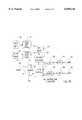
- FIG. 1is a schematic diagram showing the general scheme of the trunk cluster simple redundant switch set according to the invention
- FIG. 2Ais a diagram showing traffic flow through a multiple link trunked port
- FIG. 2Bis a diagram showing traffic flow through a multiple link trunked port of a trunk cluster interconnected with at least to one other trunk cluster;
- FIG. 3is a state diagram showing the state of the media access controllers connected to the trunk cluster
- FIG. 4is a view similar to FIG. 1 showing the logical topology as seen by the edge devices;
- FIG. 5is a schematic diagram showing the scheme for interconnecting trunk clusters
- FIG. 6is a similar to FIG. 5 showing a high speed LAN core with multiple interconnecting trunk clusters
- FIG. 7is functionally the same structure as FIG. 6 shown in the context of a Campus LAN;
- FIG. 8is functionally the same structure as FIG. 7 shown as a CORE BUILDER 9000 chassis implementation.
- the inventioncomprises a packet based high speed mesh 10 which is referred to herein as a trunk cluster.
- the trunk cluster 10includes a plurality of switches 20 or switches A through N.
- the trunk clusteris constructed of loosely coupled switches 20 based on a configuration protocol, trunked network interfaces, and optionally a reachablilty protocol.
- each switch 20, in a trunk cluster 10provides a single "shared LAN" by interconnecting two or more links 22.
- Edge devices 24are attached to the trunk cluster via links 22 running a trunk configuration.
- a plurality of linkscomprise a trunked port 30.
- FIG. 2illustrates the traffic flow 40 through a multiple link trunked port such as multiple link trunked port 30.
- FIG. 2shows transmit queue 41, receive queue 42, traffic steering means 44, steering data base 46, media access controllers (MACs) 48, physical layers 49 and connected cable (link 22).
- the trunked port 30acts as a single port, but utilizes multiple physical links 22.
- the traffic steering means 44is the logic that knows which MAC 48 to use when transmitting a packet.
- the traffic steering means 44dequeues transmit packets, examines the packet, consults the steering data base 46 and transfers the packet to the appropriate MAC 48.
- the steering data base 46is constructed by information obtained by the reachability protocol or trunk configuration management protocol (TCMP).
- TCMPtrunk configuration management protocol
- FIG. 3shows a state diagram of the MACs 48. From the perspective of trunking, a constituent MAC 48 can be in one of the following states.
- a MAC 48 in the not in use state 50has not been selected for active participation in the trunk.
- a MAC 48 in this state 50should neither transmit nor receive LLC (Logical Link Control protocol-defined in IEEE 802.2) frames. This should be the initial state for all MACs 48 of a trunk.
- a trunk MAC 48should remain in this state indefinitely, if the underlying network link 22 is down. If TCMP is enabled for a particular trunk, then the MAC 48 may remain in this state 50, even if the underlying network link is up, if TCMP determines that configuration errors preclude its active participation in the trunk.
- a MAC 48 in the selected state 52has been selected for active participation in the trunk, but it has not yet made the transition into active use. A MAC 48 in this state 52 should neither transmit nor receive LLC frames. A MAC 48 in this state is eligible to make a transition to the in use state 54 as soon as TCMP confirms that all other MACs 48 connected to the same network have also been selected. If TCMP is not enabled for a trunk, then no MAC 48 for that trunk should ever enter this state.
- a MAC 48 in the in use state 54is in active use on the trunk.
- a MAC 48 in this statemay transmit and receive LLC frames. If a trunk is manually configured (the connections are manually assigned), then a MAC 48 will transition to this state as soon as the underlying network link is up. If TCMP is enabled (for control and configuration), on the other hand, then a MAC 48 will make a transition to the in use state as soon as it confirms that all other MACs 48 connected to the same logical network (the same switch 20) have also been selected.
- TCMPa TCMP-agent
- Every MAC 48starts in the not in use state.
- a TCMP-agent(a software based means 45 writing to the traffic steering means 44) transmits a TCMP "hello message" on every MAC 48.
- the hello messagecontains the sender's TCMP node trunk or edge device ID which uniquely identifies the instance of a trunk on a particular node.
- the hello messagealso contains the trunking MAC 48 state of the transmitting MAC 48.
- the hello messageis transmitted to a special TCMP multicast address.
- the TCMP-agentmaintains a current and previous learned node trunk list (steering data base 46) for every MAC 48. Whenever the TCMP-agent receives an TCMP hello message, it adds the node trunk ID to the current list for that MAC 48. If more node trunk IDs are learned than the maximum allowable, then a list overflow indicator is set. The learned node trunk list and list overflow are set to null initially and after TCMP reselection processing.
- the TCMP-agentperforms reselection processing.
- the goal of reselectionis to select the set of MACs 48 which are eligible to go in use.
- the TCMP-agentaccomplishes this by identifying the current learned node trunk list which is common to the greatest number of MACs 48 using the following steps:
- the TCMP-agentfirst rejects any list which is null or overflowed.
- the TCMP-agentalso rejects any list which contains a received node trunk ID which is identical to the receiving trunk's node trunk ID (since this indicates that there are two MACs 48 on the same trunk which connect to the same network).
- the TCMP-agentselects the list(s) which is common to the greatest number of MACs 48. This biases selection towards activating the widest pipe (path--the activated links/switches) possible. If there is no tie, then a list is selected. Otherwise the process continues.
- the TCMP-agentselects the list(s) which is longest. For equal bandwidth pipes, this biases selection towards connecting the greatest number of nodes. If there is no tie, then a list is selected. Otherwise the process continues.
- the TCMP-agentselects the list containing the numerically smallest non-intersecting node trunk ID. For example given two lists of node trunk IDs, 3-4-6-7 and 3-4-5-8, the second list wins, because 5 is the lowest non-intersecting ID. There cannot be a tie resulting from this step.
- the TCMP-agentforces MAC 48 state changes based on the selection. (If no list has been selected, then the TCMP-agent force all MACs 48 into the not in use state). The TCMP-agent forces all MACs 48 whose current learned node trunk list differs from the selected learned node trunk list into the not in use state. The agent forces all MACs 48 with identical lists and not already in the in use state into the selected state. It allows MACs 48 with identical lists that are already in use to remain in use.
- the TCMP-agentwill copy each MAC's current learned node trunk list to its previous list and then reset each current list. This allows the reselection process to be performed completely anew each period. Note that the previous list is used during quick recovery from network link outages.
- the final step of MAC 48 activation/deactivationinvolves further MAC 48 state transitions based upon feedback received via the MAC 48 state field of subsequent hello messages.
- the TCMP-agenteffects a MAC 48 state transition from selected to in use once that MAC 48 has received a hello message from every previously learned node trunk indicating a MAC 48 state of either selected or in use. As long as the most recently received hello message from any of the learned node trunks remains not in use, then the TCMP-agent does not allow the MAC 48 to go in use. This feedback loop ensures that all of the MACs 48 on the same network have concurring reselection processes. Note that a lack of concurrence might be caused by conditions such as a stuck transmitter or various sorts of configuration errors.
- the TCMP-agentalso uses the feedback presented by the MAC 48 state field to effect MAC 48 state transitions from in use back to selected. This occurs when an in use MAC 48 receives a hello message from any previously learned node trunk indicating a MAC 48 state of not in use.
- the TCMP-agentshould ignore the MAC 48 state field in any hello messages received from any node trunks which were not previously learned. The TCMP-agent should defer processing of such new node trunks until the next reselection process.
- FIG. 4provides the view of the trunked ports of the edge devices (e.g. end device or switches) 24 as seen by the trunk configuration management protocol (TCMP).
- Each edge device 24is connected to the other edge devices 24 by multiple paths (link 22 and trunk switch 20).
- Each trunk switch 20only provides one "shared LAN" path such that it carries only a part of the traffic between edge devices 24.
- Each trunk switch 20does not need to and must not participate in any topology control or discovery protocol. Spanning tree, TCMP, IGMP, and GARP packets are flooded.
- each switch 20does not participate in any topology control or discovery protocol Unicast MAC 48 source addresses are learned and used to intelligently forward/filter unicast packets. This is desirable to minimize flooding within the "shared LAN" and increase throughput. The maximum throughput of the trunk cluster increases with each additional switch.
- the edge devices 24connect to a trunk cluster via trunked links 22.
- Basic trunking and trunking enhanced with station reachabilityare both contemplated.
- Basic trunkingmay be provided which requires at least one physical connection to each switch (A through N) 20 in the trunk cluster 10. This is referred to as equal reachability. With equal reachability, the destination address is associated with all links 22 of the trunked ports 30. This prevents any single link attachments to the trunk cluster. If a link is lost, leaving no remaining links to that switch, then the trunk configuration protocol will eliminate links connected to that switch. Effectively removing that switch from trunk cluster.
- Basic trunkinguses an "all or none" selection of MACs 48 in a Trunk group. This scheme denies use of a switch 20 in a trunk cluster 10 for all edge devices 24 if a single edge device 24 loses its last link to that switch. This maintains equal reachability for all stations or edge devices 24 over the links 22 in a trunk group.
- An enhanced trunking schememay also be used.
- the enhanced trunking schemedetermines if reachability is equal across all links in the trunk group. If reachability is unequal then the station addresses that have unequal reachability are discovered, packets destined to stations with equal reachability are steered to the transmit link using basic trunking, and packets destined to stations with unequal reachability are steered using a different method. This different method could range from static link assignment, with one destination address assigned to one physical port, to a partial trunking group, wherein one destination address can be assigned to a subset of the links 22. In the case of a two link trunk group, all stations with unequal reachability will have a static assignment to the only link they are reachable by. To implement this enhanced trunking, changes must be made to the TCMP and to the traffic steering method, and a station address distribution protocol is required
- Station unicast MAC 48 addresses(for the switches A-N 22) that are reachable via an edge device 22 can be discovered by one of the methods described below.
- the GURP applicationutilizes the GARP protocol (IEEE 802.1,q,p) (GARP Unicast Registration Protocol) and distributes the reachability of unicast MAC 48 addresses via an edge device. This protocol would only need to run when the trunk configuration management protocol discovers unequal reachability (unequal unempty trunk ID lists) on its trunked links 22.
- the GURP messagesare sent on all the links in a trunk group.
- the edge devices 24note which MAC 48 addresses (for the switches A-N 22) are not reachable on all the links 22 in a trunk cluster 10.
- the MAC 48 addresses that have unequal reachabilityare then steered by a mechanism different than the basic trunking across all the links in a trunk group. If this trunk group contains two links then the MAC 48 addresses that have unequal reachability are assigned to the only link they are reachable.
- TCARPTrusted Cluster ARP
- the reachability of a MAC 48 addressis determined by sending a query on all the links in the trunk group.
- the edge device that provides connectivity to that MAC 48 addressreplies on the link the query was received. If the replies are not heard on all the links in the Trunk group the address is determined to have unequal reachability.
- the MAC 48 addressis assigned to one of the links which is reachable. This assigned scheme can vary from static link assignment to a sub-trunking group.
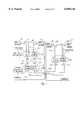
- FIG. 5shows an arrangement according to the invention wherein the trunk clusters are interconnected.
- the trunk cluster of FIG. 5is as shown in FIG. 1.
- the individual trunk switch elements 20are connected by links 22 to trunk port 30.
- each edge device 24is connected to each trunk switch 20 of the trunk cluster 10.
- the switch 20may be provided with a plurality of ports.
- a logical port 31is connected to a trunked port 30. This is provided for interconnection with other edge devices through the another trunk cluster 110.
- trunk cluster 110includes a plurality of trunk switches 120. In a manner similar to trunk cluster 10, trunk cluster 110 is connected via links 122 to trunk ports 130. The trunk ports 130 are connected via logical ports 123 to edge devices 124.
- a key feature of the interconnect systemis the use of a trunked interconnect.
- Point to point connections or links 125extend from each trunk port 137 to a trunk port 137 of the other trunk cluster.
- a trunk switch 120 of a trunk cluster 110has a logical port 131 connected to a trunked port 137.
- the trunked portincludes links 125 or point to point connections from the associated trunked port 137 to each of the trunked ports associated with the switches 20 of trunk cluster 10.
- This interconnection methodallows multiple trunk clusters to be interconnected using such point-to-point connections 125. This always provides a single loop free path from one trunk cluster to the other. Further, this isolates faults to a single trunk cluster and there is no single point of failure. Further with this interconnection system the total throughput from one trunk cluster to another is not limited by the capacity of any single switch.
- the Interconnected Trunk Management Protocolis a management protocol for the interconnection between trunk clusters (mesh switches).
- ITCMPis similar to TCMP described above. Every ITCMP hello time, a ITCMP-agent (a software based means 45, writing to the traffic steering means 44) transmits a ITCMP "hello message" on every MAC 48 of the logical trunked ports 137.
- the hello messageis as described above and includes a senders ITCMP trunk cluster ID, the trunking MAC state of the transmitting MAC.
- the unique identifieris a trunk cluster ID which is unique for the switch set. The procedure continues as noted above with resulting MAC state changes as discussed above.
- the ITCMP systemis quite similar to the TCMP system described above except trunk cluster ID's are passed around with ITCMP.
- Trunk switchestransform all received TCMP hello messages into TCMP relay messages by changing the messageType from helloMessage to helloRelay. The resulting TCMP relay messages are sent to the other Trunk Clusters.
- Trunk Switchesprocess the relay message with their TCMP agent to form a list of MAC states.
- the MAC agentperforms a logical AND of the output from the TCMP agent and the output from the ITCMP agent and writes the Steering data base with the result (see FIG. 2a).
- the ITCMP agentmust reflect the state output from the TCMP agent in the ITCMP MAC state.
- the ITCMP agentcommunicates this MAC state information in the ITCMP hello messages to prevent the other Trunk Cluster from sending packets to a MAC in the notIn Use state.
- Equal reachabilityis preferably used for trunk interconnected trunk clusters.
- the destination addressis associated with all links 125 of a trunked port 137.
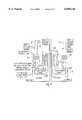
- FIG. 6shows the same arrangement as in FIG. 1 however in this situation trunk cluster 110 forms a campus interconnect device for connecting trunk cluster 10 to trunk cluster 210, via trunk cluster 110.
- the switches 120 of trunk cluster 110have additional logical ports 131 which are connected to other trunk ports 137.
- Each connected trunk port 137has individual point to point links 125 to the trunk ports 137 of trunk cluster 210.
- This additional interconnectionprovides the trunk cluster as a high throughput campus interconnect trunk cluster that can be used to connect for example a trunk cluster 10 in one building (building 1) to a trunk cluster 210 in another building (building 2).
- FIG. 7shows the concepts of the interconnect trunk cluster 110 wherein the switches 120 are not connected to edge devices. Instead, one logical port of each trunk switch 120 is connected to one of two different trunk ports 137.
- the point-to-point links 125are employed as discussed with reference to FIGS. 5 and 6.
- the trunk cluster 10is connected by links 22 to trunk ports 30 however in this case the edge devices are designated "wiring closet", namely one or more connected devices 24.
- the trunk cluster 110is also connected to trunk cluster 210. Trunk clusters 10 and 110 are provided in building 1 while trunk cluster 210 is provided in building 2. Trunk cluster 210 has links 222 to trunk ports 230 connected to wire closets 24.
- FIG. 8shows an implementation of the interconnection arrangement discussed above.
- Thisis the CORE BUILDER 9000 chassis implementation, using the 3 COM Corp. CORE BUILDER 9000 chassis product.
- two GA9sare provided in a CORE BUILDER 9000 chassis (CB 9000) and form the trunk cluster 10.
- a GA9is a 12 port Gigabit Ethernet (GE) switch with 9 GE front panel ports and 3 GE backplane ports is connected to the chassis fabric.
- the two fabric modules in the chassis CB 9000are each 24 port Gigabit Ethernet switch modules which form the trunk cluster 110.
- Each GEN 2 moduleprovides front panel access to the chassis fabric ports and to form the trunk ports 137 and three connection lines to the backplane.
- the trunk cluster fabric 210is based on two or more switches. Links 125 connect the GEN 2 devices 135. The trunked ports 137 are formed at the connection of each GEN 2 135 to the backplane and the switching fabric 210 that forms the trunk cluster. The GA9s in building 1 cooperate to form the trunk cluster 10. However, in building 2 the GA9s are connected by redundant links 322 to the wire closet stack. The trunk ports 230 are formed at the backplane based on the three connection lines to the backplane of the GA 9.
Landscapes
- Engineering & Computer Science (AREA)
- Computer Networks & Wireless Communication (AREA)
- Signal Processing (AREA)
- Small-Scale Networks (AREA)
Abstract
Description
Claims (12)
Priority Applications (2)
| Application Number | Priority Date | Filing Date | Title |
|---|---|---|---|
| US09/060,606US6058116A (en) | 1998-04-15 | 1998-04-15 | Interconnected trunk cluster arrangement |
| PCT/US1999/008221WO1999053652A1 (en) | 1998-04-15 | 1999-04-15 | Interconnected trunk cluster arrangement |
Applications Claiming Priority (1)
| Application Number | Priority Date | Filing Date | Title |
|---|---|---|---|
| US09/060,606US6058116A (en) | 1998-04-15 | 1998-04-15 | Interconnected trunk cluster arrangement |
Publications (1)
| Publication Number | Publication Date |
|---|---|
| US6058116Atrue US6058116A (en) | 2000-05-02 |
Family
ID=22030592
Family Applications (1)
| Application Number | Title | Priority Date | Filing Date |
|---|---|---|---|
| US09/060,606Expired - LifetimeUS6058116A (en) | 1998-04-15 | 1998-04-15 | Interconnected trunk cluster arrangement |
Country Status (2)
| Country | Link |
|---|---|
| US (1) | US6058116A (en) |
| WO (1) | WO1999053652A1 (en) |
Cited By (43)
| Publication number | Priority date | Publication date | Assignee | Title |
|---|---|---|---|---|
| US20020046357A1 (en)* | 1999-12-28 | 2002-04-18 | Jiandong Huang | Software-based fault tolerant networking using a single LAN |
| US6466574B1 (en)* | 1998-06-05 | 2002-10-15 | International Business Machines Corporation | Quality of service improvement of internet real-time media transmission by transmitting redundant voice/media frames |
| US6567403B1 (en)* | 1998-04-30 | 2003-05-20 | Hewlett-Packard Development Company, L.P. | Virtual-chassis switch network topology |
| US20030099247A1 (en)* | 2001-11-27 | 2003-05-29 | Rene Toutant | Programmable interconnect system for scalable router |
| US6608812B1 (en)* | 1999-01-15 | 2003-08-19 | 3Com Corporation | Trunk arrangement in a computer network with intra trunk switch connections |
| US20030169734A1 (en)* | 2002-03-05 | 2003-09-11 | Industrial Technology Research Institute | System and method of stacking network switches |
| US6687751B1 (en)* | 2000-01-28 | 2004-02-03 | 3Com Corporation | Multi-point link aggregation spoofing |
| US20040049706A1 (en)* | 2002-09-10 | 2004-03-11 | Stephen Strong | Systems and methods for synchronizing time stamps |
| US6801953B2 (en)* | 1997-11-28 | 2004-10-05 | 3Com Corporation | Trunking in stacked communication devices |
| US20040267901A1 (en)* | 2003-06-30 | 2004-12-30 | Gomez Juan Carlos | System and method for filtering stale messages resulting from membership changes in a distributed computing environment |
| US20050010691A1 (en)* | 2003-06-30 | 2005-01-13 | Randy Oyadomari | Synchronization of timestamps to compensate for communication latency between devices |
| US20050010695A1 (en)* | 2000-10-17 | 2005-01-13 | Trillium Digital Systems, Inc. | High availability/high density system and method |
| US20050060402A1 (en)* | 2002-09-10 | 2005-03-17 | Randy Oyadomari | Propagation of signals between devices for triggering capture of network data |
| US20050060413A1 (en)* | 2003-06-13 | 2005-03-17 | Randy Oyadomari | Discovery and self-organization of topology in multi-chassis systems |
| US20050147087A1 (en)* | 2001-05-30 | 2005-07-07 | Tekelec | Scalable, reliable session intiation protocol (SIP) signaling routing node |
| US20050281191A1 (en)* | 2004-06-17 | 2005-12-22 | Mcgee Michael S | Monitoring path connectivity between teamed network resources of a computer system and a core network |
| US7006438B2 (en)* | 2001-05-31 | 2006-02-28 | Turin Networks | Distributed control of data flow in a network switch |
| US20060248106A1 (en)* | 2005-03-17 | 2006-11-02 | Milne Andrew J | Interpolated timestamps in high-speed data capture and analysis |
| US7228348B1 (en) | 2002-08-13 | 2007-06-05 | Finisar Corporation | System and method for triggering communications data capture |
| US20070177589A1 (en)* | 2006-01-31 | 2007-08-02 | Fujitsu Limited | Network system and node redundancy method of network system |
| US20070206492A1 (en)* | 2003-01-07 | 2007-09-06 | Corrigent Systems Ltd. | Hierarchical virtual private lan service protection scheme |
| US20080034120A1 (en)* | 2006-08-04 | 2008-02-07 | Oyadomari Randy I | Multiple domains in a multi-chassis system |
| US20080056234A1 (en)* | 2006-08-04 | 2008-03-06 | Tekelec | Methods, systems, and computer program products for inhibiting message traffic to an unavailable terminating SIP server |
| US20080080384A1 (en)* | 2006-10-02 | 2008-04-03 | Atkins Mark G | System and method for implementing an infiniband error log analysis model to facilitate faster problem isolation and repair |
| US20080126874A1 (en)* | 2006-09-25 | 2008-05-29 | Finisar Corporation | Arm and rollback in a multi-chassis system |
| US7406038B1 (en)* | 2002-04-05 | 2008-07-29 | Ciphermax, Incorporated | System and method for expansion of computer network switching system without disruption thereof |
| US20090040923A1 (en)* | 2007-07-31 | 2009-02-12 | Apirux Bantukul | Systems, methods, and computer program products for distributing application or higher layer communications network signaling entity operational status information among session initiation protocol (sip) entities |
| US7606230B1 (en) | 2004-05-10 | 2009-10-20 | Marvell International Ltd. | Link aggregation for routed ports |
| US7911937B1 (en)* | 2003-05-30 | 2011-03-22 | Sprint Communications Company L.P. | Communication network architecture with diverse-distributed trunking and controlled protection schemes |
| US20120300773A1 (en)* | 2011-05-27 | 2012-11-29 | Hitachi Cable, Ltd. | Network system and method of operating the same |
| US20130021930A1 (en)* | 2011-07-19 | 2013-01-24 | Hitachi Cable, Ltd. | Network system |
| WO2013188791A1 (en)* | 2012-06-15 | 2013-12-19 | Citrix Systems, Inc. | Systems and methods for cluster lag |
| US8724450B2 (en) | 2010-11-24 | 2014-05-13 | Hitachi Metals, Ltd. | Network relay system and method of controlling a network relay system |
| US20140136677A1 (en)* | 2011-07-21 | 2014-05-15 | Huawei Technologies Co., Ltd. | Method and device of interface registration for a network device to join in a cluster system |
| US8737412B2 (en) | 2010-11-24 | 2014-05-27 | Hitachi Metals, Ltd. | Network relay system and method of automatically setting a network relay system |
| US8830994B2 (en) | 2011-09-27 | 2014-09-09 | Hitachi Metals, Ltd. | Network system |
| US8948168B2 (en) | 2011-07-19 | 2015-02-03 | Hitachi Metals, Ltd. | Network system |
| US9154577B2 (en) | 2011-06-06 | 2015-10-06 | A10 Networks, Inc. | Sychronization of configuration file of virtual application distribution chassis |
| US9477563B2 (en) | 2011-01-11 | 2016-10-25 | A10 Networks, Inc. | Virtual application delivery chassis system |
| US9961130B2 (en) | 2014-04-24 | 2018-05-01 | A10 Networks, Inc. | Distributed high availability processing methods for service sessions |
| US10318288B2 (en) | 2016-01-13 | 2019-06-11 | A10 Networks, Inc. | System and method to process a chain of network applications |
| US10742559B2 (en) | 2014-04-24 | 2020-08-11 | A10 Networks, Inc. | Eliminating data traffic redirection in scalable clusters |
| US11012931B2 (en) | 2019-05-24 | 2021-05-18 | Oracle International Corporation | Methods, systems, and computer readable media for enhanced signaling gateway (SGW) status detection and selection for emergency calls |
Families Citing this family (5)
| Publication number | Priority date | Publication date | Assignee | Title |
|---|---|---|---|---|
| US6826195B1 (en) | 1999-12-28 | 2004-11-30 | Bigband Networks Bas, Inc. | System and process for high-availability, direct, flexible and scalable switching of data packets in broadband networks |
| US6611526B1 (en) | 2000-05-08 | 2003-08-26 | Adc Broadband Access Systems, Inc. | System having a meshed backplane and process for transferring data therethrough |
| US6853680B1 (en) | 2000-05-10 | 2005-02-08 | Bigband Networks Bas, Inc. | System and process for embedded cable modem in a cable modem termination system to enable diagnostics and monitoring |
| US20100153523A1 (en)* | 2008-12-16 | 2010-06-17 | Microsoft Corporation | Scalable interconnection of data center servers using two ports |
| CN102904787A (en)* | 2011-07-27 | 2013-01-30 | 中兴通讯股份有限公司 | Method and device for local bus bridging and data transmission |
Citations (14)
| Publication number | Priority date | Publication date | Assignee | Title |
|---|---|---|---|---|
| US4201889A (en)* | 1978-03-17 | 1980-05-06 | International Telephone And Telegraph | Distributed control digital switching system |
| US4201890A (en)* | 1978-03-17 | 1980-05-06 | International Telephone And Telegraph | Multiport digital switching element |
| US4201891A (en)* | 1978-03-17 | 1980-05-06 | International Telephone And Telegraph Corporation | Expandable digital switching network |
| US5088091A (en)* | 1989-06-22 | 1992-02-11 | Digital Equipment Corporation | High-speed mesh connected local area network |
| US5138615A (en)* | 1989-06-22 | 1992-08-11 | Digital Equipment Corporation | Reconfiguration system and method for high-speed mesh connected local area network |
| US5179558A (en)* | 1989-06-22 | 1993-01-12 | Digital Equipment Corporation | Routing apparatus and method for high-speed mesh connected local area network |
| US5295154A (en)* | 1991-10-01 | 1994-03-15 | Norand Corporation | Radio frequency local area network |
| US5333131A (en)* | 1990-08-17 | 1994-07-26 | Hitachi, Ltd. | Packet switching method and system with self-routing switch |
| US5428636A (en)* | 1993-05-03 | 1995-06-27 | Norand Corporation | Radio frequency local area network |
| US5473599A (en)* | 1994-04-22 | 1995-12-05 | Cisco Systems, Incorporated | Standby router protocol |
| US5487065A (en)* | 1993-05-26 | 1996-01-23 | The Trustees Of Columbia University In The City Of New York | Method and apparatus for supporting mobile communications in asynchronous transfer mode based networks |
| US5497504A (en)* | 1994-05-13 | 1996-03-05 | The Trustees Of Columbia University | System and method for connection control in mobile communications |
| US5600637A (en)* | 1994-02-22 | 1997-02-04 | Fujitsu Limited | System and method for traffic distribution, intermediate device and end device |
| US5740156A (en)* | 1986-09-16 | 1998-04-14 | Hitachi, Ltd. | Packet switching system having self-routing switches |
- 1998
- 1998-04-15USUS09/060,606patent/US6058116A/ennot_activeExpired - Lifetime
- 1999
- 1999-04-15WOPCT/US1999/008221patent/WO1999053652A1/enactiveApplication Filing
Patent Citations (14)
| Publication number | Priority date | Publication date | Assignee | Title |
|---|---|---|---|---|
| US4201890A (en)* | 1978-03-17 | 1980-05-06 | International Telephone And Telegraph | Multiport digital switching element |
| US4201891A (en)* | 1978-03-17 | 1980-05-06 | International Telephone And Telegraph Corporation | Expandable digital switching network |
| US4201889A (en)* | 1978-03-17 | 1980-05-06 | International Telephone And Telegraph | Distributed control digital switching system |
| US5740156A (en)* | 1986-09-16 | 1998-04-14 | Hitachi, Ltd. | Packet switching system having self-routing switches |
| US5088091A (en)* | 1989-06-22 | 1992-02-11 | Digital Equipment Corporation | High-speed mesh connected local area network |
| US5138615A (en)* | 1989-06-22 | 1992-08-11 | Digital Equipment Corporation | Reconfiguration system and method for high-speed mesh connected local area network |
| US5179558A (en)* | 1989-06-22 | 1993-01-12 | Digital Equipment Corporation | Routing apparatus and method for high-speed mesh connected local area network |
| US5333131A (en)* | 1990-08-17 | 1994-07-26 | Hitachi, Ltd. | Packet switching method and system with self-routing switch |
| US5295154A (en)* | 1991-10-01 | 1994-03-15 | Norand Corporation | Radio frequency local area network |
| US5428636A (en)* | 1993-05-03 | 1995-06-27 | Norand Corporation | Radio frequency local area network |
| US5487065A (en)* | 1993-05-26 | 1996-01-23 | The Trustees Of Columbia University In The City Of New York | Method and apparatus for supporting mobile communications in asynchronous transfer mode based networks |
| US5600637A (en)* | 1994-02-22 | 1997-02-04 | Fujitsu Limited | System and method for traffic distribution, intermediate device and end device |
| US5473599A (en)* | 1994-04-22 | 1995-12-05 | Cisco Systems, Incorporated | Standby router protocol |
| US5497504A (en)* | 1994-05-13 | 1996-03-05 | The Trustees Of Columbia University | System and method for connection control in mobile communications |
Cited By (71)
| Publication number | Priority date | Publication date | Assignee | Title |
|---|---|---|---|---|
| US6801953B2 (en)* | 1997-11-28 | 2004-10-05 | 3Com Corporation | Trunking in stacked communication devices |
| US6567403B1 (en)* | 1998-04-30 | 2003-05-20 | Hewlett-Packard Development Company, L.P. | Virtual-chassis switch network topology |
| US6466574B1 (en)* | 1998-06-05 | 2002-10-15 | International Business Machines Corporation | Quality of service improvement of internet real-time media transmission by transmitting redundant voice/media frames |
| US6608812B1 (en)* | 1999-01-15 | 2003-08-19 | 3Com Corporation | Trunk arrangement in a computer network with intra trunk switch connections |
| US20020046357A1 (en)* | 1999-12-28 | 2002-04-18 | Jiandong Huang | Software-based fault tolerant networking using a single LAN |
| US6687751B1 (en)* | 2000-01-28 | 2004-02-03 | 3Com Corporation | Multi-point link aggregation spoofing |
| US20060080469A1 (en)* | 2000-10-17 | 2006-04-13 | Trillium Digital Systems, Inc. | High availability/high density system and method |
| US20050010695A1 (en)* | 2000-10-17 | 2005-01-13 | Trillium Digital Systems, Inc. | High availability/high density system and method |
| WO2002054179A3 (en)* | 2000-12-29 | 2003-05-15 | Honeywell Int Inc | Software-based fault tolerant networking using a single lan |
| US20050147087A1 (en)* | 2001-05-30 | 2005-07-07 | Tekelec | Scalable, reliable session intiation protocol (SIP) signaling routing node |
| US7631093B2 (en) | 2001-05-30 | 2009-12-08 | Tekelec | Scalable, reliable session initiation protocol (SIP) signaling routing node |
| US20050157707A1 (en)* | 2001-05-30 | 2005-07-21 | Tekelec | Scalable, reliable session initiation protocol (SIP) signaling routing node |
| US7006438B2 (en)* | 2001-05-31 | 2006-02-28 | Turin Networks | Distributed control of data flow in a network switch |
| US20030099247A1 (en)* | 2001-11-27 | 2003-05-29 | Rene Toutant | Programmable interconnect system for scalable router |
| US7274702B2 (en)* | 2001-11-27 | 2007-09-25 | 4198638 Canada Inc. | Programmable interconnect system for scalable router |
| US20030169734A1 (en)* | 2002-03-05 | 2003-09-11 | Industrial Technology Research Institute | System and method of stacking network switches |
| US7139267B2 (en) | 2002-03-05 | 2006-11-21 | Industrial Technology Research Institute | System and method of stacking network switches |
| US7406038B1 (en)* | 2002-04-05 | 2008-07-29 | Ciphermax, Incorporated | System and method for expansion of computer network switching system without disruption thereof |
| US7228348B1 (en) | 2002-08-13 | 2007-06-05 | Finisar Corporation | System and method for triggering communications data capture |
| US6941482B2 (en)* | 2002-09-10 | 2005-09-06 | Finisar Corporation | Systems and methods for synchronizing time stamps |
| US20050060402A1 (en)* | 2002-09-10 | 2005-03-17 | Randy Oyadomari | Propagation of signals between devices for triggering capture of network data |
| US8266271B2 (en) | 2002-09-10 | 2012-09-11 | Jds Uniphase Corporation | Propagation of signals between devices for triggering capture of network data |
| US20040049706A1 (en)* | 2002-09-10 | 2004-03-11 | Stephen Strong | Systems and methods for synchronizing time stamps |
| US20070206492A1 (en)* | 2003-01-07 | 2007-09-06 | Corrigent Systems Ltd. | Hierarchical virtual private lan service protection scheme |
| US7911937B1 (en)* | 2003-05-30 | 2011-03-22 | Sprint Communications Company L.P. | Communication network architecture with diverse-distributed trunking and controlled protection schemes |
| US20050060413A1 (en)* | 2003-06-13 | 2005-03-17 | Randy Oyadomari | Discovery and self-organization of topology in multi-chassis systems |
| US7827248B2 (en) | 2003-06-13 | 2010-11-02 | Randy Oyadomari | Discovery and self-organization of topology in multi-chassis systems |
| US7562154B2 (en)* | 2003-06-30 | 2009-07-14 | International Business Machines Corporation | System and method for filtering stale messages resulting from membership changes in a distributed computing environment |
| US20040267901A1 (en)* | 2003-06-30 | 2004-12-30 | Gomez Juan Carlos | System and method for filtering stale messages resulting from membership changes in a distributed computing environment |
| US8190722B2 (en) | 2003-06-30 | 2012-05-29 | Randy Oyadomari | Synchronization of timestamps to compensate for communication latency between devices |
| US20050010691A1 (en)* | 2003-06-30 | 2005-01-13 | Randy Oyadomari | Synchronization of timestamps to compensate for communication latency between devices |
| US8085778B1 (en) | 2004-05-10 | 2011-12-27 | Marvell International Ltd. | Voltage regulator |
| US7606230B1 (en) | 2004-05-10 | 2009-10-20 | Marvell International Ltd. | Link aggregation for routed ports |
| US20050281191A1 (en)* | 2004-06-17 | 2005-12-22 | Mcgee Michael S | Monitoring path connectivity between teamed network resources of a computer system and a core network |
| US9491084B2 (en)* | 2004-06-17 | 2016-11-08 | Hewlett Packard Enterprise Development Lp | Monitoring path connectivity between teamed network resources of a computer system and a core network |
| US20060248106A1 (en)* | 2005-03-17 | 2006-11-02 | Milne Andrew J | Interpolated timestamps in high-speed data capture and analysis |
| US7779340B2 (en) | 2005-03-17 | 2010-08-17 | Jds Uniphase Corporation | Interpolated timestamps in high-speed data capture and analysis |
| US20070177589A1 (en)* | 2006-01-31 | 2007-08-02 | Fujitsu Limited | Network system and node redundancy method of network system |
| US20080034120A1 (en)* | 2006-08-04 | 2008-02-07 | Oyadomari Randy I | Multiple domains in a multi-chassis system |
| US20080056234A1 (en)* | 2006-08-04 | 2008-03-06 | Tekelec | Methods, systems, and computer program products for inhibiting message traffic to an unavailable terminating SIP server |
| US7630385B2 (en) | 2006-08-04 | 2009-12-08 | Oyadomari Randy I | Multiple domains in a multi-chassis system |
| US7929419B2 (en) | 2006-08-04 | 2011-04-19 | Tekelec | Methods, systems, and computer program products for inhibiting message traffic to an unavailable terminating SIP server |
| US7764695B2 (en) | 2006-09-25 | 2010-07-27 | Oyadomari Randy I | Arm and rollback in a multi-chassis system |
| US20080126874A1 (en)* | 2006-09-25 | 2008-05-29 | Finisar Corporation | Arm and rollback in a multi-chassis system |
| US7872982B2 (en) | 2006-10-02 | 2011-01-18 | International Business Machines Corporation | Implementing an error log analysis model to facilitate faster problem isolation and repair |
| US20080080384A1 (en)* | 2006-10-02 | 2008-04-03 | Atkins Mark G | System and method for implementing an infiniband error log analysis model to facilitate faster problem isolation and repair |
| US7742421B2 (en) | 2007-07-31 | 2010-06-22 | Tekelec | Systems, methods, and computer program products for distributing application or higher layer communications network signaling entity operational status information among session initiation protocol (SIP) entities |
| US20090040923A1 (en)* | 2007-07-31 | 2009-02-12 | Apirux Bantukul | Systems, methods, and computer program products for distributing application or higher layer communications network signaling entity operational status information among session initiation protocol (sip) entities |
| US8724450B2 (en) | 2010-11-24 | 2014-05-13 | Hitachi Metals, Ltd. | Network relay system and method of controlling a network relay system |
| US8737412B2 (en) | 2010-11-24 | 2014-05-27 | Hitachi Metals, Ltd. | Network relay system and method of automatically setting a network relay system |
| US9838472B2 (en) | 2011-01-11 | 2017-12-05 | A10 Networks, Inc. | Virtual application delivery chassis system |
| US9477563B2 (en) | 2011-01-11 | 2016-10-25 | A10 Networks, Inc. | Virtual application delivery chassis system |
| US10530847B2 (en) | 2011-01-11 | 2020-01-07 | A10 Networks, Inc. | Virtual application delivery chassis system |
| US20120300773A1 (en)* | 2011-05-27 | 2012-11-29 | Hitachi Cable, Ltd. | Network system and method of operating the same |
| US8787374B2 (en)* | 2011-05-27 | 2014-07-22 | Hitachi Metals, Ltd. | Network system including lower and upper switches and link group interconnecting lower switches to upper switches, and method of operating the same |
| US10298457B2 (en) | 2011-06-06 | 2019-05-21 | A10 Networks, Inc. | Synchronization of configuration file of virtual application distribution chassis |
| US9596134B2 (en) | 2011-06-06 | 2017-03-14 | A10 Networks, Inc. | Synchronization of configuration file of virtual application distribution chassis |
| US9154577B2 (en) | 2011-06-06 | 2015-10-06 | A10 Networks, Inc. | Sychronization of configuration file of virtual application distribution chassis |
| US9912538B2 (en) | 2011-06-06 | 2018-03-06 | A10 Networks, Inc. | Synchronization of configuration file of virtual application distribution chassis |
| US20130021930A1 (en)* | 2011-07-19 | 2013-01-24 | Hitachi Cable, Ltd. | Network system |
| US9264253B2 (en)* | 2011-07-19 | 2016-02-16 | Hitachi Metals, Ltd. | Network system |
| US8948168B2 (en) | 2011-07-19 | 2015-02-03 | Hitachi Metals, Ltd. | Network system |
| US9577871B2 (en)* | 2011-07-21 | 2017-02-21 | Huawei Technologies Co., Ltd. | Method and device of interface registration for a network device to join in a cluster system |
| US20140136677A1 (en)* | 2011-07-21 | 2014-05-15 | Huawei Technologies Co., Ltd. | Method and device of interface registration for a network device to join in a cluster system |
| US8830994B2 (en) | 2011-09-27 | 2014-09-09 | Hitachi Metals, Ltd. | Network system |
| US8996652B2 (en) | 2012-06-15 | 2015-03-31 | Citrix Systems, Inc. | Systems and methods for cluster LAG |
| WO2013188791A1 (en)* | 2012-06-15 | 2013-12-19 | Citrix Systems, Inc. | Systems and methods for cluster lag |
| US9961130B2 (en) | 2014-04-24 | 2018-05-01 | A10 Networks, Inc. | Distributed high availability processing methods for service sessions |
| US10742559B2 (en) | 2014-04-24 | 2020-08-11 | A10 Networks, Inc. | Eliminating data traffic redirection in scalable clusters |
| US10318288B2 (en) | 2016-01-13 | 2019-06-11 | A10 Networks, Inc. | System and method to process a chain of network applications |
| US11012931B2 (en) | 2019-05-24 | 2021-05-18 | Oracle International Corporation | Methods, systems, and computer readable media for enhanced signaling gateway (SGW) status detection and selection for emergency calls |
Also Published As
| Publication number | Publication date |
|---|---|
| WO1999053652A1 (en) | 1999-10-21 |
Similar Documents
| Publication | Publication Date | Title |
|---|---|---|
| US6058116A (en) | Interconnected trunk cluster arrangement | |
| US6195349B1 (en) | Scalable logical LAN | |
| US6195351B1 (en) | Logical switch set | |
| US7656788B2 (en) | High-reliability cluster management | |
| US20050044211A1 (en) | Self-healing tree network | |
| US7848264B1 (en) | Method and apparatus for rapidly reconfiguring computer networks | |
| US6570881B1 (en) | High-speed trunk cluster reliable load sharing system using temporary port down | |
| US20060029056A1 (en) | Virtual machine task management system | |
| US20020147800A1 (en) | Method and apparatus for rapidly reconfiguring computer networks using a spanning tree algorithm | |
| US7447223B2 (en) | Switching mesh with broadcast path redundancy | |
| US7881307B2 (en) | Multiple-instance meshing | |
| Cisco | Configuring Ethernet and Fast Ethernet Switching Modules | |
| Cisco | Configuring Ethernet and Fast Ethernet Switching Modules | |
| Cisco | Configuring Ethernet and Fast Ethernet Switching Modules | |
| Cisco | Configuring Ethernet and Fast Ethernet Switching Modules | |
| Cisco | Configuring Ethernet and Fast Ethernet Switching Modules | |
| Cisco | Configuring Ethernet and Fast Ethernet Switching Modules | |
| Cisco | Configuring STP | |
| Cisco | Concepts | |
| Cisco | Concepts | |
| Cisco | Configuring Ethernet and Fast Ethernet Switching Modules | |
| Cisco | Configuring Ethernet and Fast Ethernet Switching Modules | |
| Cisco | Configuring Ethernet and Fast Ethernet Switching Modules | |
| Cisco | Configuring Ethernet and Fast Ethernet Switching Modules | |
| Cisco | Configuring Ethernet and Fast Ethernet Switching Modules |
Legal Events
| Date | Code | Title | Description |
|---|---|---|---|
| AS | Assignment | Owner name:3COM CORPORATION, CALIFORNIA Free format text:ASSIGNMENT OF ASSIGNORS INTEREST;ASSIGNORS:HISCOCK, JAMES SCOTT;BACKES, FLOYD;REEL/FRAME:009106/0009 Effective date:19980415 | |
| STCF | Information on status: patent grant | Free format text:PATENTED CASE | |
| FPAY | Fee payment | Year of fee payment:4 | |
| FPAY | Fee payment | Year of fee payment:8 | |
| FEPP | Fee payment procedure | Free format text:PAYOR NUMBER ASSIGNED (ORIGINAL EVENT CODE: ASPN); ENTITY STATUS OF PATENT OWNER: LARGE ENTITY Free format text:PAYER NUMBER DE-ASSIGNED (ORIGINAL EVENT CODE: RMPN); ENTITY STATUS OF PATENT OWNER: LARGE ENTITY | |
| AS | Assignment | Owner name:HEWLETT-PACKARD COMPANY, CALIFORNIA Free format text:MERGER;ASSIGNOR:3COM CORPORATION;REEL/FRAME:024630/0820 Effective date:20100428 | |
| AS | Assignment | Owner name:HEWLETT-PACKARD COMPANY, CALIFORNIA Free format text:CORRECTIVE ASSIGNMENT TO CORRECT THE SEE ATTACHED;ASSIGNOR:3COM CORPORATION;REEL/FRAME:025039/0844 Effective date:20100428 | |
| FPAY | Fee payment | Year of fee payment:12 | |
| AS | Assignment | Owner name:HEWLETT-PACKARD DEVELOPMENT COMPANY, L.P., TEXAS Free format text:ASSIGNMENT OF ASSIGNORS INTEREST;ASSIGNOR:HEWLETT-PACKARD COMPANY;REEL/FRAME:027329/0044 Effective date:20030131 | |
| AS | Assignment | Owner name:HEWLETT-PACKARD DEVELOPMENT COMPANY, L.P., TEXAS Free format text:CORRECTIVE ASSIGNMENT PREVIUOSLY RECORDED ON REEL 027329 FRAME 0001 AND 0044;ASSIGNOR:HEWLETT-PACKARD COMPANY;REEL/FRAME:028911/0846 Effective date:20111010 | |
| AS | Assignment | Owner name:HEWLETT PACKARD ENTERPRISE DEVELOPMENT LP, TEXAS Free format text:ASSIGNMENT OF ASSIGNORS INTEREST;ASSIGNOR:HEWLETT-PACKARD DEVELOPMENT COMPANY, L.P.;REEL/FRAME:037079/0001 Effective date:20151027 |